Transportable Radio Guide - caraham.org · 2013-04-27 · DAN-MKT-117 Transportable Radio System...
56
Document: DAN-MKT-117 Version 2.0 Transportable Radio Guide January 7, 2010 Transportable Radio Systems
Transcript of Transportable Radio Guide - caraham.org · 2013-04-27 · DAN-MKT-117 Transportable Radio System...

Document: DAN-MKT-117 Version 2.0
���������������
Transportable Radio Guide
January 7, 2010
Transportable Radio Systems

DAN-MKT-117 Transportable Radio System Guide January 7, 2010
Page 2 of 56
Table of Contents
1. INTRODUCTION ................................................................................................................................ 4 1.1 ABOUT DANIELS ELECTRONICS....................................................................................................... 4 1.2 INTENDED AUDIENCE ...................................................................................................................... 4 1.3 HOW THIS GUIDE WORKS ................................................................................................................. 5 1.4 PURPOSE.......................................................................................................................................... 5 1.5 TYPICAL APPLICATIONS .................................................................................................................. 6 1.6 BENEFITS......................................................................................................................................... 6
2. SECTION 2 – REPEATER BASICS .................................................................................................. 7 2.1 WHAT IS A REPEATER? .................................................................................................................... 7
2.1.1 Simplex Communications........................................................................................................ 8 2.1.2 Duplex Communications......................................................................................................... 8
2.2 HOW DOES A REPEATER WORK?....................................................................................................... 9 2.3 OTHER TYPES OF REPEATERS .......................................................................................................... 9
2.3.1 Bi-Directional Amplifier (BDA).............................................................................................. 9 2.3.2 Vehicular Repeater ............................................................................................................... 10
2.4 BASE STATIONS............................................................................................................................. 10 2.5 BENEFITS OF A TRANSPORTABLE RADIO ....................................................................................... 10 2.6 COMPONENTS OF A TRANSPORTABLE RADIO ................................................................................ 11
2.6.1 Transmitters and Receivers (TX/RX) .................................................................................... 11 2.6.2 Duplexers.............................................................................................................................. 12 2.6.3 Antenna................................................................................................................................. 13 2.6.4 Enclosure.............................................................................................................................. 14 2.6.5 Power Supply........................................................................................................................ 14
2.7 SUMMARY OF REQUIREMENTS ...................................................................................................... 15 2.8 THE TRADE-OFFS OF A PRACTICAL SOLUTION THAT MEETS YOUR NEEDS....................................... 15
3. SECTION 3 – REAL WORLD PROBLEMS AND THEIR SOLUTIONS................................... 16 3.1 NO COVERAGE AREA ..................................................................................................................... 16
3.1.1 Temporary Communications during a Forest Fire............................................................... 17 3.1.2 Forest Fire Fighting - Ground to Air Communications ....................................................... 17 3.1.3 Search and Rescue in a remote area .................................................................................... 18 3.1.4 Communications for Natural Resource Exploration ............................................................ 19 3.1.5 Scientific Research in the Antarctic...................................................................................... 20 3.1.6 Vehicle accident in a valley that has poor or inadequate coverage ..................................... 21 3.1.7 Multi Agency Interoperability - Columbine, Colorado......................................................... 22 3.1.8 Multi-Agency Interoperability – Alameda County................................................................ 22 3.1.9 Coverage in Buildings and Tunnels...................................................................................... 23
3.2 EXISTING INFRASTRUCTURE FAILURES .......................................................................................... 24 3.3 SPECIAL APPLICATIONS................................................................................................................. 25
3.3.1 Secure Undercover Operations ............................................................................................ 25 3.3.2 Forward Observer / Sniper Communications....................................................................... 26 3.3.3 Diplomatic security............................................................................................................... 27 3.3.4 Customs inspection on a vessel............................................................................................. 28
4. SECTION 4 – THE “WORKING” TRANSPORTABLE RADIO................................................. 29 4.1 FEATURES ..................................................................................................................................... 29
4.1.1 Analog vs. P25...................................................................................................................... 29 4.1.2 Encryption ............................................................................................................................ 29 4.1.3 Conventional or Trunked Channels...................................................................................... 30
4.2 TRANSMITTER & RECEIVER (TX / RX).......................................................................................... 30 4.2.1 Transmitter ........................................................................................................................... 30 4.2.2 Receiver ................................................................................................................................ 30 4.2.3 Transceivers ......................................................................................................................... 30

DAN-MKT-117 Transportable Radio System Guide January 7, 2010
Page 3 of 56
4.2.4 Frequency Bands .................................................................................................................. 31 4.3 CALCULATING SYSTEM GAIN AND RANGE .................................................................................... 32
4.3.1 Transmitter Gains................................................................................................................. 32 4.3.2 Receiver Sensitivity............................................................................................................... 32 4.3.3 Antenna Gains ...................................................................................................................... 32 4.3.4 Duplexers.............................................................................................................................. 32 4.3.5 Cable Losses ......................................................................................................................... 32 4.3.6 Free Space Loss.................................................................................................................... 33 4.3.7 Obstruction Losses ............................................................................................................... 33 4.3.8 Fade Margin ......................................................................................................................... 34 4.3.9 Path Calculation Worksheet ................................................................................................. 34
4.4 DUPLEXERS ................................................................................................................................... 35 4.4.1 Isolation................................................................................................................................ 35 4.4.2 How do I provide isolation to the repeater?......................................................................... 36 4.4.3 Duplexer Characteristics...................................................................................................... 37
4.5 ANTENNAS .................................................................................................................................... 39 4.5.1 Radiation Patterns and Types............................................................................................... 39 4.5.2 Antenna Size and Characteristics ......................................................................................... 40 4.5.3 Practical Considerations for your antenna .......................................................................... 41
4.6 ENCLOSURES – CHOOSING THE RIGHT CASE .................................................................................. 42 4.6.1 Open/Closed Lid Operation.................................................................................................. 42 4.6.2 Case Selection....................................................................................................................... 43 4.6.3 Weight................................................................................................................................... 44 4.6.4 Case Size Selection ............................................................................................................... 45
4.7 POWER SUPPLIES ........................................................................................................................... 46 4.7.1 AC......................................................................................................................................... 46 4.7.2 DC ........................................................................................................................................ 47
4.8 OPERATION AND MAINTENANCE ................................................................................................... 49 5. APPENDIX - REFERENCES ........................................................................................................... 50
5.1 GLOSSARY..................................................................................................................................... 50 5.2 REFERENCE DOCUMENTS .............................................................................................................. 51 5.3 TRANSPORTABLE RADIO RFQ SHEET............................................................................................ 52

DAN-MKT-117 Transportable Radio System Guide January 7, 2010
Page 4 of 56
1. Introduction
1.1 About Daniels Electronics
For the past 60 years Daniels has provided customers worldwide with highly reliable Base Stations and Repeaters that are designed for robust operation in rugged environments, extreme temperature conditions and applications where low current consumption is a key requirement (solar, wind or battery powered).
Daniels has been a pioneering member of the P25 Digital standard for radio system interoperability between emergency response governmental organizations, providing enhanced functionality and encryption. Our products operate between 29 - 869 MHz and are available in a variety of Base Station and Repeater configurations for two way voice and mobile data applications.
Our self-servicing customers range from Forestry and National Park services through Police and Fire departments and on to Utility and Transportation groups. Our products have been deployed in every imaginable situation from the Antarctic to Hawaiian mountaintops, enabling respondents to Forest Fires, Ground Zero rescue and routine patrols.
Daniels is an industry leader in Analog and P25 radio systems design. We offer modular rack mounted Base Stations and Repeaters, as well as a family of transportable solutions capable of operating in the following bands:
• Low Band VHF
• VHF AM
• VHF FM
• UHF (380-520 MHz)
• 700 MHz
• 800 MHz
1.2 Intended Audience
This guide has been created to introduce non-technical personnel and end-users to information that will allow them to make the best choice in choosing a Transportable Communications Solution that is tailored to the emergency management or mutual aid requirements.
Daniels Electronics has a long history of making customized Transportable Radio solutions for its various customers and their many unique requirements. We have learnt over the years that each customer has a combination of particular requirements that need to be met to make sure their system is going to be successful in as many of their expected scenarios as possible.
You will find that as you work through this guide, there will be a number of choices you need to make about the requirements for your Transportable Radio system, and that each choice has a combination of trade-offs that must be understood. We hope this guide will allow you to make the best possible educated decision as to the features of your Transportable Radio system and the trade-offs that come with it.

DAN-MKT-117 Transportable Radio System Guide January 7, 2010
Page 5 of 56
1.3 How this guide works
In preparing this guide, we recognized that first responders have more than just their Transportable Radio system to think about on a daily basis. While this is all we think about at Daniels Electronics, it is only one of a long list of items needed for a First Responders “tool-box”. Therefore, we have arranged this document into four key sections:
• Section One – Introduction • Sections Two - Repeater & Base Station basics - If you only have time for an overview to
the key components you need to address in helping design your Transportable Radio – READ THIS SECTION!!
• Section Three – Real World communications problems that we have helped solve at
Daniels Electronics using a variety of Transportable Radio solutions. Take a look! Someone may have already solved the very problem that caused you to start reading this book in the first place….
• Section Four – This is a technical discussion of all the key components found in Section
Two. If you would like to have a better understanding of the “whys” and “hows” of a particular component of your system, this section will give you everything you need.
1.4 Purpose
When disasters strike, it usually happens at the worst time, in the worst location and somewhere that no longer has communications. Transportable Radio Systems support portable and temporary communication solutions that can be quickly deployed with minimal complexity.
A Transportable Radio such as the unit shown to the right may be a standard Land Mobile Radio (LMR) radio repeater specially packaged in a briefcase for portability with all the accessories required to instantly create a local repeater site. Capable of interfacing to First Responders’ handsets and mobiles, it creates a relay between First Responders and also links back to existing infrastructure. Transportable Radios are available for VHF, UHF and 700/800 MHz operation in either analog or digital P25 modes and can support cross banding between bands to enable different agencies to communicate together. Optional HF or Satellite interfaces enable communications to remote locations should existing infrastructure be damaged or unavailable.
Packaging options such as high visibility waterproof cases are available for outdoor applications (forest fire fighting) where the ability to work in any weather condition for extended periods is required. For tactical applications a Briefcase Repeater (as shown above) provides a compact, lightweight, package offering ease of deployment by one person. Both packages can provide quick connect AC or DC power and Antenna connectors along with battery backup, duplexers, antenna masts and trickle chargers allowing any first responder to setup and operate the radio system.
Press and Pull latches
ET-4 Polyethylene Briefcase
Optional rugged metalstorage contained
In-line wheels
Soft grip handle
Telescoping Pull handle
Power supply, batterybackup and speaker
Daniels standard subrack (Analog or digital)
Optional duplexer

DAN-MKT-117 Transportable Radio System Guide January 7, 2010
Page 6 of 56
1.5 Typical Applications
Applications for Transportable Radios are as diverse as the First Responder agencies (Police, Fire, Ambulance, Search and Rescue, Civil Defense, Forest Fire Fighters, Reconstruction and Recovery operations) using them. In fact it is hard to imagine a First Responder group that doesn’t need a Transportable Radio System.
• Forest Fires – Transportable Radios are deployed during Forest Fire season providing on-site communications. The repeater may be configured with cross banding capabilities to facilitate communications with spotter helicopters or water bombers fighting the fires.
• Natural Disasters – Hurricanes, earthquakes and tsunamis can destroy fixed infrastructure (as was the case with Hurricane Katrina in New Orleans), Transportable Radio Systems provide temporary communications to on-site first responders and also provide additional communications infrastructure for first responders that may be coming into the region to assist.
• Multiagency Tactical response – require tactical or covert communications with encryption. Radio equipment packaged in a compact, low visibility black suitcase will not be obvious to the public or allude to the nature of the equipment being used.
• Search and Rescue – Search and Rescue applications need communications that may not normally be served by the existing fixed infrastructure. A Transportable Radio provides localized communications in a collapsed building recovery zone, tunnel or a rural region. Optional Satellite or radio links may be used to link back to an existing network.
1.6 Benefits
Transportable Radios provide instant communications anywhere, anytime. Able to be set up in a matter of minutes, they provide first responder agencies with an instant solution to communications challenges. Key benefits include:
• Consumes minimal power allowing operation from solar panels or batteries
• Intended for all weather and operational conditions (including high altitudes)
• Capable of operation in any frequency bands
• Supports cross banding between frequencies
• Compact and easy to deploy by a single person
• Analog or Digital P25 (Clear or Secure)
• Waterproof, Shockproof, Vibration proof
• Rapidly deployable
• Reliable

DAN-MKT-117 Transportable Radio System Guide January 7, 2010
Page 7 of 56
2. Section 2 – Repeater Basics
2.1 What is a repeater?
Radio signals operate over line-of-sight paths. This implies that you must be able to see the radio with which you wish to communicate. Actually, contact between radios slightly beyond line-of-sight distances is often possible, owing to reflection or refraction of the radio waves. Physical restrictions of signal paths between radio users (such as mountains or buildings) can disrupt system operation.
The diagram below on the left shows the line-of-sight signal paths between the portables and from the portables to the base station at the office. At the far right, note the blocked signal path between the mobile and the office caused by the hill which prevents the mobile from communicating.
To extend coverage, a radio repeater is required. A repeater is nothing more than a radio or combination of radios connected in such a way that it simply passes on or “repeats” anything that it hears. In the diagram below the repeater enables all radios to communicate together.

DAN-MKT-117 Transportable Radio System Guide January 7, 2010
Page 8 of 56
2.1.1 Simplex Communications
To understand how a repeater actually works, it is best to first start with portable-portable communications. In this scenario, communications is on a single common frequency from one user’s radio to another user’s radio directly. The transmitting radio is transmitting its signal on a single frequency, which we will refer to as F1. While it is transmitting on F1, only the transmitter is connected to the antenna, and therefore it cannot receive at the same time.
On the other end of this scenario is the receiving radio, whose receiver is connected to its antenna (the default scenario for any radio), and is always listening to F1 as long as its user does not try to make their own transmission.
F1
This direct method of communication is referred to as Simplex Communication. A single frequency is used to allow for single direction communications. Users of this system can talk back and forth between each other, but they must take turns talking. This is how all standard portable and mobile subscriber radios work.
2.1.2 Duplex Communications
Duplex Communications on the other hand allow for simultaneous transmitting and receiving of two different signals. This scenario requires 2 distinct frequencies, and obviously a radio that is capable of both transmitting and receiving at the same time. While this is not how portable and mobile radios work, this is the general concept behind the operation of a repeater.
Repeater Site
VHF F2
VHF F1

DAN-MKT-117 Transportable Radio System Guide January 7, 2010
Page 9 of 56
2.2 How does a repeater work?
A repeater receives a signal at a particular location, and at the exact same time re-transmits that signal, at a much higher strength, to the immediate vicinity. This is very handy for getting a signal to go around or over large objects such as mountains, or to take a weak signal and boost it for penetration into a building or other structures.
To do this a repeater makes use of duplex communications. A repeater requires a pair of frequencies; a Receive Frequency (F1 for example) and a separate Transmit Frequency (in this case, F2). When the repeater receives a signal on F1, it simultaneously transmits the received signal on F2. All of the radio users in the coverage area of the repeater that are listening to F2 will hear the signal that was originally sent out on F1.
For all users in the field who want to communicate through the repeater, they will transmit on their portable radios using F1 and receive on F2. While the portable radios in the field are still making use of Simplex Communications, the repeater is making use of Duplex Communications to provide the added coverage.
2.3 Other Types of Repeaters
2.3.1 Bi-Directional Amplifier (BDA)
A Bi-Directional Amplifier (BDA) is a common solution for in-building or tunnel communications. A Bi-Directional Amplifier system consists of one or more amplifiers located inside the confined environment and in turn connected to an external antenna network. The external antenna, usually located on the roof of the building, or mouth of the tunnel, receives the signal coming from the external radio site. The BDA then amplifies the signal and retransmits it into the building or tunnel. A subscriber unit within the building can use the BDA to extend their portable radio coverage and communicate with the external system. The BDA listens for incoming traffic inside the confined space, amplifies it and retransmits it to the external system, hence bi-directional. A BDA can be relatively inexpensive, however, the supporting infrastructure of cabling, antennas, filters and power supplies quickly add to the total installed cost. Furthermore, unless BDAs are adjusted correctly, they can create interference issues with themselves, with other BDAs, or with the existing radio system.

DAN-MKT-117 Transportable Radio System Guide January 7, 2010
Page 10 of 56
2.3.2 Vehicular Repeater
A vehicular repeater is a specialized radio repeater mounted in a vehicle that is used in conjunction with a mobile radio to effectively expand the range of a portable radio in the field. To illustrate this concept, an officer leaves his vehicle and begins transmitting on his portable radio. The 3-5 Watt portable radio signal is boosted through the vehicular repeater, thus enabling transmission at much greater distances. For in building or tunnel scenarios, the vehicular repeater can improve the local communications in an emergency response. The vehicular repeater typically is not limited by a power source and is highly mobile. However, it is limited by its ability to be moved from location to location and used in confined or remote environments.
2.4 Base Stations
Base station radio systems are used to communicate between a dispatch/command center and mobiles or portable-equipped radio users in the field. Base stations typically need to communicate on multiple channels and frequently the radio itself needs to be physically located at a remote location so as to provide better radio coverage.
Digital base station radios can support either secure or clear digital mode operation (encrypted or non-encrypted) using AES 256-bit or DES-OFB 64-bit encryption modules compliant to the security requirements of FIPS 140-2. Digital base stations have the ability to automatically detect and differentiate between analog and digital as well as encrypted or non-encrypted signals.
A local or wide area network can be used to link the dispatcher/command center and the base station site. Using the P25 Digital Fixed Station Interface (DFSI) standard, an all digital (optionally encrypted) communication path can be created from the portable to the dispatch center connected to the base station.
2.5 Benefits of a Transportable Radio
Normally, a repeater system is a fixed installation used in combination with base stations and other equipment – collectively known as “infrastructure”. One or more repeaters and base stations can be used to provide reliable wide area coverage for the users in the field. However, due to the physical limitations of installing “infrastructure equipment” permanently in locations that are appropriate for housing communications equipment (radio towers, building tops, mountains, etc.) there will always be areas that are not adequately covered. This may be due to being beyond the coverage area of the system or working inside a large building that provides challenges for signal penetration (very common in most urban areas).
In these areas of little or no radio coverage, a Transportable Radio can be very beneficial in bringing the coverage strengths found in a normally fixed piece of infrastructure equipment to the scene of operations. By providing the users on-scene with a local repeater, the communications between those first responders on-scene can be very effective. Whether the Transportable Radio is a small, low-power, tactical unit or a large, high-power, multi-agency/multi-band system providing interoperability, a well planned Transportable Radio system will be a very effective tool for all users that are operating in an area that typically would not have any radio coverage at all.

DAN-MKT-117 Transportable Radio System Guide January 7, 2010
Page 11 of 56
2.6 Components of a Transportable Radio
The following diagram and subsections overview the components of a Transportable Radio. Comprehensive details on each component are provided in Chapter 4.
2.6.1 Transmitters and Receivers (TX/RX)
The transmitter (TX) and receiver (RX) are the key components of a Transportable Radio system. A repeater, whether permanently installed infrastructure equipment or a Transportable Radio, will always have a Transmitter and Receiver that are separate from each other. Further to this, the Transmitter and Receiver will each have their own frequency. A repeater may not have the same Transmit and Receive frequency.
The Transmitter in a repeater system is designed to be capable of transmitting on only the desired frequency and not broadcast excessive noise and signals on other frequencies that may be operating in the area. Typically a repeater transmitter is higher power than a Portable or Mobile Radio, but it does not have to be. Remember that the location of the repeater and its antenna is as important as the radiated power of the repeater itself. Optional an amplifier may be added to the transmitter to provide higher output power. For transportable radios this is typically less than 50 Watts due to proximity of the users and current consumption.
The Receiver in a repeater system is designed to be highly sensitive to low signal strengths so that users in the field with low power radio equipment such as portable radios, can communicate with the repeater. However, the repeater receiver must also be capable of rejecting all the other signals that it may hear on adjacent channels. This is what makes a repeater receiver different from a portable or mobile radio.

DAN-MKT-117 Transportable Radio System Guide January 7, 2010
Page 12 of 56
2.6.1.1 Transceivers
Transportable Radios can also be built from transceivers which are the same type of radio used in a mobile or portable. A transceiver as its name implies (Transmitter / Receiver = Transceiver) is a radio that combines the transmitter and receiver circuitry together. Compared to a distinct transmitter and receiver pair, a transceiver is a simpler device offering the benefits of smaller size, lower cost and lower current consumption. Hence the reason all portables and mobiles are transceiver designs. The tradeoff compared with a distinct transmitter / receiver pair is lower performance specifications, lower reliability and having to replace the entire unit in the event of a failure.
2.6.2 Duplexers
As mentioned above, a repeater will always have distinct Transmit and Receive frequencies. Even though the receiver is designed to ignore signals that are not on its tuned frequency, the transmitter in the repeater will be transmitting a relatively high strength signal at the same time that the receiver is receiving its signal. To prevent the transmitter from interfering with the receiver during this “repeat” operation, we need to protect the receiver, or isolate it from the transmitter.
One way to isolate the Receiver from the Transmitter is to use two separate antennas and place them some distance apart. How far the antennas need to be away from each other is dependent on the frequency of operation, the power of the Transmitter and the proximity of the actual Transmit and Receive frequencies. Make no mistake, typically these two antennas need to be quite a distance apart (tens of meters) in either vertical or horizontal separation.
There is a much easier way to protect the receiver other than running hundreds of feet of cable in opposite directions! A duplexer can be used to filter out the transmitter frequency before the receiver sees it. A duplexer is a radio frequency filter that allows you to connect both the Transmitter and Receiver to a single antenna. The portion that is connected to the Transmitter will only allow the Transmitters frequency to pass. The portion connected to the receiver will only allow the receiver frequency to pass. This way the high strength signal created by the Transmitter cannot be fed back into the Receiver and cause interference or damage the receiver with too much RF power. From a Transportable Radio standpoint, the duplexer approach makes things much simpler since only a single antenna needs to be deployed on-scene and it facilitates a compact package.
RX - UHF F2 456.775 MHz
TX - UHF F1 451.775 MHz
RX - UHF F2 456.775 MHz
TX - UHF F1 451.775 MHz
Duplexer Image www.comprodcom.com
Repeater Site
RX - UHF F2 456.775 MHz
TX - UHF F1 451.775 MHz
RX - UHF F2 456.775 MHz
TX - UHF F1 451.775 MHz
RX - UHF F2 456.775 MHz
TX - UHF F1 451.775 MHz
UHF Repeaterwww.danelec.com

DAN-MKT-117 Transportable Radio System Guide January 7, 2010
Page 13 of 56
2.6.3 Antenna
Whether you opt for the dual-antenna deployment or the more commonly used single antenna with a duplexer, pay careful attention in selecting the right antenna for your application. The antenna receives the signal from the users in the field and sends out the new repeated signal from the Transportable Radio transmitter.
There are a number of considerations in selecting an antenna:
• Gain – Antennas can provide gain. This can reduce the amount of RF power needed by the transmitter or it can increase the coverage range. In Section 4.2.9 we show that for a UHF repeater with a 5 Watt output the expected coverage range is on the order of 10 kms. To double the coverage distance you need a gain of 6 db or 4 times the RF output power!
• Radiation Pattern – antennas can be made to direct the coverage in a specific pattern. For example a Yagi antenna (shown above) will direct most of the signal to the “front” with little or no signal delivered to the sides or back of the antenna. An Omni directional antenna will radiate in all directions (360°).
• Bandwidth – The range of frequencies that the antenna is capable of covering
• Antenna type – antennas are available in an almost unlimited number of shapes and styles. Common examples include:
- The “Rubber Duck” – a small but convenient antenna, commonly found on portable radios. It has poor transmit and receive specifications but is the easiest to deploy.
- Magnetic Mount vehicle antenna – Assuming a metal surface is handy for mounting this antenna such as the roof of a car, this can be a convenient antenna for rapid deployment. Has better transmit and receive characteristics than the Rubber Duck.
- Yagi antenna – requires some form of mast mounting but offers good gain characteristics and is also directional.
- Stealth Panel antennas – are specifically designed to be disguised in a case or look like something other then a radio antenna.

DAN-MKT-117 Transportable Radio System Guide January 7, 2010
Page 14 of 56
2.6.4 Enclosure
Depending on the nature of the Transportable Radio deployment the enclosure can be critical to the success or failure of your system. If the enclosure is not sealed to the outside world, and the deployment will be in harsh weather conditions with high levels of rain and dust exposure, then eventual failure of the system is likely.
There are a variety of enclosures available depending on your requirements:
• Aluminum Cases – These cases are very rugged and capable of air-tight ratings for the harshest of wet environments. These cases are also a good option for outdoor deployments such as forest fire fighting or search and rescue. Pressure release valves enable the cases to be transported in airplanes without pressurization.
• Polyethylene Cases – Offer a wide selection of sizes (briefcases, suitcase) with options such as pull-out handles and roller wheels. Ideal for sub-urban and urban deployments.
• Polyethylene Rack Mount Cases – Larger versions of the polyethylene suitcases. These cases typically have entire racks inside for mounting large communications systems such as multi-agency/multi-band systems or Transportable Trunked systems with multiple channels. Typically they are for very heavy equipment and require more than one person to lift. Ideal for permanent mounting inside vehicles or mobile command centers.
2.6.5 Power Supply
The final critical part of the Transportable Radio is the power supply. An analysis of the possible deployment scenarios needs to be done prior to specifying the desired power source. Common power supplies used for Transportable Radios include:
• AC Power – very simple to connect to, just plug the repeater into the “wall” and turn it on. This is only appropriate for some applications as even urban deployments can find a system with only AC power very limiting in where it can be deployed. Either that or get a very long extension cord…
• Generators – gas or diesel generators can be used. These offer either an AC or DC output. Capable of very high output powers, the big issue here is supplying fuel.
• Battery Power (Internal or External) – Very simple to operate, just turn on the repeater. However internal batteries mean the repeater is heavier and has a shorter run time since only small batteries can be used. By adding a second case to the repeater system, significant increases in run times can be achieved as the external battery can be much larger than its internal relative. However, a second case adds size and weight. Users of the system must always remember to recharge the batteries between uses and the repeater must be very efficient with its current draw.
• Solar Powered – By adding a solar panel to the repeater, it is possible to achieve extremely long run times. This is very helpful for deployments that will be for an undetermined amount of time such as a Natural Disaster recovery or Forest Fire. This solution adds a third case to the deployment however and again the repeater needs to be very efficient with its current draw.
• Wind Generators – can provide power in remote locations for long periods of time as a supplement to solar and battery systems.

DAN-MKT-117 Transportable Radio System Guide January 7, 2010
Page 15 of 56
2.7 Summary of Requirements
A transportable radio system is intended to provide radio coverage on a temporary basis in an area not normally served or to replace an existing radio site that has gone out of service. As such there are 4 key issues to keep in mind in selecting your Transportable Radio System:
• Features – What are the essential features the radio system must provide? o Will the radio be conventional or trunked? o Number of channels required? o Will it operate in analog, P25 digital, P25 digital encrypted mode or all? o What frequency band(s) are you using? o Desired coverage area and transmit power required?
• Ease of Deployment – Where will the system be set up? o Source of power? o Setup time – minutes / hours? o Total weight and size – number of people for setup? o Type of transportation required (hand carried or in a helicopter)? o Type of Enclosure - Outdoor / Indoor, Visible / Stealth?
• Operation – Who will set up and operate the system? o Level of training required? o Linked to the existing radio network? o Ease of repairing a failure? o Can the system be reconfigured?
• Affordability – What will the system cost over its operational life? o Initial cost? o Power costs? o Maintenance and service costs? o Expected operational life?
2.8 The trade-offs of a practical solution that meets your needs
The most important thing to remember when choosing the key features for your Transportable Radio as summarized above is that there are always trade-offs. For example, a system cannot be extremely small AND be high power at the same time. By going small the system cannot accommodate amplifiers or large power supplies.
Priority Trade-Off
Small Size Low Power Output, single channel, few options
Easy to use Few options, less flexible
Maximum coverage/penetration High-power required, therefore large size
Multi-Channel Requires large custom filter or two antenna
Multi-Band Each band requires its own repeater and duplexer, therefore this system will be larger the more bands that are required
Internal Battery Weight, batteries are heavy
Long deployments Additional power sources required such as battery banks or solar power

DAN-MKT-117 Transportable Radio System Guide January 7, 2010
Page 16 of 56
3. Section 3 – Real world problems and their solutions
This section outlines some of the different scenarios in which a Transportable Radio is required and provides example deployments.
3.1 No coverage area
Transportable Radios are an obvious choice when communications are required in an area that is not served by the existing infrastructure. This could be:
a) A remote area where fire fighters are dealing with a forest fire
b) A search and rescue operation in a remote area beyond the coverage of the fixed infrastructure or in an urban area where the infrastructure has failed
c) Oil / mineral exploration or scientific research in a remote area with local communications for the exploration / scientific team and a satellite link back to head office.
d) Emergency response to a vehicle accident on a remote highway or valley with poor coverage from the existing radio network
e) Expanded coverage and capacity during an emergency when many first responder agencies are participating on-site.
f) In building / tunnel dead zones during a fire, emergency or routine maintenance
As shown in the diagram to the left, the upper handheld is obstructed from communicating with the office due to the hills. If that handheld is a first responder dealing with any of the above scenarios then there is no communication back to the support center. A Transportable Radio strategically located at a high elevation can enable communications between the remote area and the support center as illustrated in the second diagram on the right.

DAN-MKT-117 Transportable Radio System Guide January 7, 2010
Page 17 of 56
3.1.1 Temporary Communications during a Forest Fire
The British Columbia Ministry of Forestry and the US National Interagency Fire Center (NIFC) have developed Fire Repeaters that can be quickly deployed to temporarily enhance radio communications for fire fighters, where coverage in the area is poor. They can be linked into the existing networks, or work as stand alone units.
The Fire Repeater (shown to the left below) consists of a radio repeater (receiver, transmitter, duplexer and magnetic mount antenna) in a high visibility all weather aluminum orange case, a 35 AH battery (in the silver box) and a solar panel (to charge the battery during the day). Combined with an antenna and mast an entire radio site can be quickly deployed by vehicle or helicopter to a hilltop to provide communications coverage during the response to a forest fire (as shown below right).
http://www.for.gov.bc.ca/his/radio/Overview/overview.htm
3.1.2 Forest Fire Fighting - Ground to Air Communications
To facilitate the establishment of rapid communication links between ground base fire crews and supporting water bomber crews, a transportable air to ground crossband repeater is the ideal solution. A ground to air crossband repeater allows FM ground radios (VHF or UHF) to communicate with AM VHF airband radios. This is ideal for providing ground based fire fighters or search and rescue crews with direct communication to supporting aircraft and helicopters. A transportable crossband repeater system enables system interoperability by changing frequency bands between the two radio systems.

DAN-MKT-117 Transportable Radio System Guide January 7, 2010
Page 18 of 56
3.1.3 Search and Rescue in a remote area
An example deployment of Transportable Radios during a search and rescue incident in a remote area occurred in Butte County California in December 2007. You probably remember the news story about Laci Peterson, who went missing on Christmas Eve, 2002. During the months until Laci's body was found, her mom, Sharon Rocha was impressed by the work of the search and rescue teams. Much to Rocha's surprise, most search and rescue in the United States is done by volunteers and she was shocked at how little funding they receive. To rectify this situation, she created the Laci and Conner Peterson Foundation http://www.lacipeterson.com/ to provide grants to search and rescue groups. One of the groups the foundation gave money to was Butte County Search and Rescue http://www.buttesar.org/ to purchase a Transportable Radio Repeater.
Butte County's Lt. Dan Newman explains the difference the Transportable Radio has made to his organization. "It's a real remote area. Our radios didn't work," he says noting that their searches often took them out of range of their base station. In particular, he's reminded of a search he was involved in during Christmas 2007. It was just outside of Chico, near Paradise.
There was a father, 2 boys and a girl. They'd gone to cut down a Christmas tree but a storm came in and they got lost. They weren't prepared. They were just wearing jeans and instead of staying put they tried to walk back to civilization. The problem was they kept walking in the wrong direction, further and further out of radio range. The next day, they did the same thing. The next day, they walked even further. It wasn't until the fourth day that the team of 100 searchers finally located the family.
Without the Transportable Radio, the search would not have been as well coordinated and the family may not have been found alive. "We're using the repeater 2-3 times a month now," says Lt. Newman. "This has definitely paid for itself over and over."
Butte County purchased a VHF analog 8 watt Transportable Radio with an internal battery. For longer operations, they just hook it up to a car battery. The radio itself is housed in a rugged polyethylene case and withstands extreme weather. "We use it in all conditions," says Lt. Newman. "We’ve been using it for two years and it’s been working great."

DAN-MKT-117 Transportable Radio System Guide January 7, 2010
Page 19 of 56
3.1.4 Communications for Natural Resource Exploration
Establishing communications in areas not normally served by radio infrastructure can be a challenge, particularly for remote camps that are hundreds of miles from the nearest community. Crews exploring large areas require the teams to be in constant communication with each other for safety (government regulations – OSHA, WCB) and logistics. As well they need to be able to communicate to head office regularly to provide updates on their findings. An economical and easy to deploy communication solution is needed.
Satellite Telephone interface in a Transportable Case
A Transportable Radio can be interfaced to a satellite telephone system (fixed link or satellite telephone) allowing communications to and from any telephone in the world. The transportable Land Mobile Radio (LMR) repeater is housed in a waterproof case that is easy to deploy by a single person, consumes minimal current allowing it to be powered by solar panels or batteries and is compact for ease of transportation via helicopter or ATV.
The LMR system provides communications for the exploration crews using standard LMR two
way handhelds over the exploration area. When communication back to head office is required, the radio user in the field accesses the satellite telephone by a DTMF sequence and then uses the satellite to dial out to any telephone. Other users can access the LMR repeater from anywhere in the world by dialing into the satellite telephone system (a telephone number enabled for the satellite telephone).
The LMR repeater with satellite telephone interface provides a complete communication solution in a single package. For applications requiring communications between radio users in the field where no microwave or land line links exist and head office, a satellite interface (Iridium or Inmarsat) on the LMR transportable radio creates connectivity, anywhere, anytime.

DAN-MKT-117 Transportable Radio System Guide January 7, 2010
Page 20 of 56
3.1.5 Scientific Research in the Antarctic
The Antarctic is renowned for its cold temperatures where lows of -50ºC (-58ºF) are common and winds can exceed 185 km/h (115 mph). A Daniels transportable VHF repeater has been operational in the Antarctic since the mid 1990s providing communications from summer research camps a mile (1.6 kms) up on the Ross Ice Shelf back to McMurdo Station. In this harsh environment the survival of scientists and other workers in these camps (like the one in the photo to the right) requires dependable communications with McMurdo Station, more than 50 miles (80 kms) across the Ross Ice Shelf. Helicopters provide the only access to these field camp sites, and very-high-frequency (VHF) radios provide the only communications.
VHF frequencies have proved to work well when the line-of-sight propagation limitation is overcome with transportable repeaters. The repeater supports multiple communications channels and meteorological equipment. The system can be assembled easily and flown to the repeater site. At the site, the repeater is unhooked from the lifting rigging, the antenna and accessory cables are installed and connected, wind braces are rigged and the repeater is turned on. The system is then in operation and ready for use immediately. The open-frame structure has solar panels on all sides and an equipment case with four structure-leveling jacks, four deployable outriggers, and equipment shock protection (see photo below.) The equipment case contains a 19-inch equipment rack, the Daniels VHF repeater, the solar power subsystem, the meteorological monitoring subsystem and the RF distribution subsystem.
The Daniels repeater includes a receiver, transmitter, 30 Watt power amplifier operating in the 136 – 150 MHz band and a control card. The solar power subsystem is composed of four 83W solar panels, a 30A charging controller, two adjustable low voltage disconnects and six sealed lead-acid (gelled) batteries. Each solar panel (side-mounted, to maximize sunlight incidence) provides power to the charging controller and then to the 12 Vdc bus and storage batteries. Since its first season (1993-1994) of deployment the repeaters have performed flawlessly and carry both aircraft and field party communications.
�
DAN-MKT-117 Transportable Radio System Guide January 7, 2010
Page 21 of 56
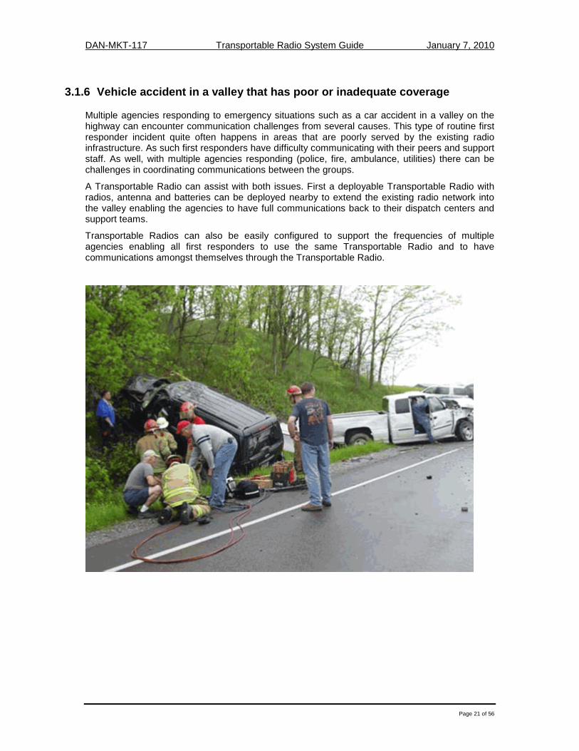
3.1.6 Vehicle accident in a valley that has poor or inadequate coverage
Multiple agencies responding to emergency situations such as a car accident in a valley on the highway can encounter communication challenges from several causes. This type of routine first responder incident quite often happens in areas that are poorly served by the existing radio infrastructure. As such first responders have difficulty communicating with their peers and support staff. As well, with multiple agencies responding (police, fire, ambulance, utilities) there can be challenges in coordinating communications between the groups.
A Transportable Radio can assist with both issues. First a deployable Transportable Radio with radios, antenna and batteries can be deployed nearby to extend the existing radio network into the valley enabling the agencies to have full communications back to their dispatch centers and support teams.
Transportable Radios can also be easily configured to support the frequencies of multiple agencies enabling all first responders to use the same Transportable Radio and to have communications amongst themselves through the Transportable Radio.

DAN-MKT-117 Transportable Radio System Guide January 7, 2010
Page 22 of 56
3.1.7 Multi Agency Interoperability - Columbine, Colorado
Further examples of the need for interoperability between agencies that were met with a Transportable Radio, include the Columbine High School Incident that occurred in 1999, at Columbine High School in Columbine, Colorado, near Denver.
With 46 separate agencies responding it was inevitable that they would be operating different emergency radio channels in different frequency bands. Daniels had previously provided a Transportable Radio to the Denver Fire Department (the orange case on top of the fire truck) to support interagency communications. The Transportable Radio deployed on scene was crucial in enabling interagency communications at the school.
3.1.8 Multi-Agency Interoperability – Alameda County
In Alameda County California, first responders responding to major incidents in the county involving multiple agencies had a problem communicating with each other, since each agency communicated in different frequency bands. To address this problem the county deployed transportable crossband repeaters (shown to the right) that covered all 5 bands in use in the county.
Each Transportable Radio system contains 30 Watt Lowband, VHF, UHF, T-Band and 800 MHz repeaters. All repeaters are capable of being crossbanded with any or all of the other repeaters allowing for a single point of contact across all the bands. Now when a major emergency occurs, the Transportable Radio can be quickly deployed on-site to enable all first responders to communicate, with no changes to their existing handhelds or mobiles.

DAN-MKT-117 Transportable Radio System Guide January 7, 2010
Page 23 of 56
3.1.9 Coverage in Buildings and Tunnels
For fire fighters and paramedics, in building coverage is a major concern in all their deployments. Despite increasing building code regulation requiring the deployment of Bi-Directional Amplifiers in building for emergency response, the vast majority of buildings are not up to the latest building code standards. A Transportable Radio addresses this problem by ensuring that communications exist where you need them, when you need them.
A battery powered Transportable Radio can be quickly deployed on the sidewalk, in the lobby or on various floors to provide in building communications and ensure the fire fighters have communications as they respond to the in building emergency. Transportable Radios can also offer cross banding to enable low frequency radios (VHF) to be used in the building for better propagation (see Section 4.1.4) and then crossbanded to the existing radio network outside working at a higher frequency (UHF or 800 MHz).
Similarly, emergency communications in tunnels is also a concern since the same propagation challenges exist going through ground and along enclosed spaces. As well in an emergency it is highly probable that whatever communications were normally there may have been damaged in the emergency.
Transportable Radios can be deployed at the entrance to the tunnels to extend radio coverage into the tunnel. They can also be carried into the tunnel to ensure communications exist all the way in the tunnel to the emergency location.

DAN-MKT-117 Transportable Radio System Guide January 7, 2010
Page 24 of 56
3.2 Existing infrastructure failures
When a catastrophe such as a hurricane, earthquake, or a tsunami hits, existing infrastructure can be damaged or destroyed. To maintain communications during the emergency and in the post recovery stages, Transportable Radios play an invaluable role.
A Transportable Radio can be deployed at the site of the existing fixed infrastructure that was damaged to provide a rapid replacement for the damaged equipment. In many instances if the Transportable Radio is configured identically to the fixed site, the replacement appears to operate seamlessly in the network to the first responders.
After catastrophic events like 9/11, Hurricane Katrina and the Asian Tsunami, the strong supporting response from the first responder community can overwhelm any communications system as the number of radio users is well beyond that envisioned in the original design of the fixed infrastructure. To supplement the existing radio network, Transportable Radios can quickly add additional capacity and coverage during the emergency response.
After 9/11 and Hurricane Katrina, the National Interagency Fire Center http://www.nifc.gov/ in Boise Idaho provided a network of Transportable Radios to reestablish downed communications sites in both cities. The photo above left is an example of a Transportable Radio being deployed on the Empire State building, to rebuild the LMR network in lower Manhattan that was lost, after the main transmitter tower on the World Trade Center was lost. Similarly, Transportable Radios were deployed throughout New Orleans to replace infrastructure damaged by the hurricane.

DAN-MKT-117 Transportable Radio System Guide January 7, 2010
Page 25 of 56
3.3 Special Applications
This section examines a number of specialized uses for Transportable Radios where covert and secure communications are mission critical.
3.3.1 Secure Undercover Operations
Undercover agencies are moving to digital encrypted P25 based body wire microphones (mics) for undercover operations to prevent certain “groups” under investigation from monitoring the known government channels. Body wire mics are very low power (~10 milliwatts) with ranges of only a few hundred feet. They require a repeater nearby to extend RF coverage enabling support teams to keep their distance from the operation. To avoid monitoring, P25 encryption is essential.
The Bureau of Alcohol Tobacco and Firearms (ATF) http://www.atf.gov/ approached Daniels Electronics looking for a fully compliant P25 encrypted compact portable repeater for field deployment. The Special Response Teams (SRT) are typically equipped with P25 body worn surveillance transmitters that operate in the VHF band. For security the transmitters use P25 AES or DES-OFB encryption.
In their research they found that existing transportable systems are too large, have batteries that are too heavy and the radio is too complex to operate in the ATF – SRT application. ATF requested a basic P25 encrypted transportable repeater that was small and easy to disguise. The unit needed to be as compact as possible in size, as the repeater and battery pack may be carried in a gym bag.
A key requirement for ATF was to have a repeater that used “D” sized batteries and offered an operational life of 3 to 3 1/2 hours with a 100% duty cycle (always transmitting). The rationale for “D” size batteries is that it allows a team to buy, at the last minute, “off the shelf” alkaline type batteries to power the repeater for an operation. This makes last minute deployment easy since the users only need to install fresh batteries before use.
A P25 encrypted Transportable Radio (6 watt transmitter) meeting the above requirements extends the coverage range of the Body Wire Mic from a few hundred feet to thousands of feet enabling the support team to be a discreet distance of several city blocks away from the operation; far enough to be undetected, but close enough to lend immediate assistance when needed. This is illustrated in the representative coverage maps below.

DAN-MKT-117 Transportable Radio System Guide January 7, 2010
Page 26 of 56
3.3.2 Forward Observer / Sniper Communications
During field trials of the Transportable Repeaters that Daniels Electronics has developed, an alternative application was also found to have been met by the tactical repeater. Various law enforcement agencies and their personnel are routinely called upon to act as forward observers lying prone, similar to a sniper. For these applications the requirements are similar to the undercover operation; however a longer talk time is required on the order of 5 hours. Even with a regular portable, the coverage range offered is very poor since the observer (and the radio) is lying prone on the ground, putting the antenna on the radio in the least optimal orientation for signal coverage. Thus the repeater is needed to provide improved coverage between the observer and the support teams.
In this particular application the duty cycle is quite low (5% talk, 5% listen, 90% idle). However all other requirements for the repeater remain the same – “D” cell batteries, compact, rugged, small, easy to carry and importantly still P25 encrypted. The “D” cell transportable repeater described above was able to meet this requirement without further modifications since the low current consumption of the radio supported an operational battery life of more then 12 hours.
Horizontal Antenna = Poor RF coverage

DAN-MKT-117 Transportable Radio System Guide January 7, 2010
Page 27 of 56
3.3.3 Diplomatic security
The security protection of senior government officials as well as diplomats, and the coordination of their support teams require transportable radio repeaters that can go wherever the officials and diplomats travel.
A Transportable Radio system that is easy to deploy, compact, self contained and possibly secure with encryption would meet the obvious requirements of this application. Depending on the entourage of support staff and size of the security detail, a large radio system may be required rather then just a single channel. In these instances a transportable trunked radio system may be needed to offer sufficient capacity for all the radio users. Trunked radio systems are specifically designed to offer large call capacities since they support multiple simultaneous calls. For example a 5 channel trunked system in a public safety environment could support several hundred portable and mobile radio users.
Transportable Trunked radio systems are a challenge since they are more complex than single frequency conventional radio repeaters. This means more equipment, higher power consumption, heavier equipment and complex duplexers to combine the many frequencies onto a single antenna system. All of these requirements are challenging but not impossible. Shown below to the right for example, is a 5 channel transportable P25 trunked radio system that can be moved around in a small van or helicopter. This same system can also be packaged in smaller stackable transportable cases (shown below left) to enable it to be transported in any vehicle and then carried and set up by a single radio technician.
An added consideration for this type of application is whether the equipment will be used internationally and if so will it be transported by the diplomatic community. If the transportable cases are orange in colour they can be considered to be diplomatic pouches and thus can bypass international customs inspection like the rest of a diplomat’s baggage. Packaging the radio equipment in orange cases simplifies its transportability internationally for diplomats.

DAN-MKT-117 Transportable Radio System Guide January 7, 2010
Page 28 of 56
3.3.4 Customs inspection on a vessel
Temporary communications during marine vessel inspections is increasingly becoming a vital requirement, but is still a major technical challenge due to all the steel passage ways that inhibit RF propagation onboard. This applies whether the customs and border agency is inspecting a container ship upon arrival in port or during a hostile boarding off the coast of Somalia in pursuit of pirates.
A fully self contained Transportable Radio (radio, battery and antenna) can be quickly set up on the deck of the ship or carried in a knapsack during the boarding, to enable communications amongst the boarding team once on board, as well as back to the command center in port or on the supporting naval vessel. Both the Canadian and US Navies have used Transportable Radios for ship inspections by their boarding teams.
The rugged, compact design enables ease of transportability, ease of operation and long battery life for the duration of their inspection. P25 encryption ensures security of communications.
The real benefit the navies discovered was the extensive coverage offered on board a vessel. During trials with the US Navy it was discovered that a UHF repeater was able to propagate the length of the ship as well as down 4 decks. This has eliminated the previous communication technology of leaky coaxial cable and also enables rapid deployment on a vessel to be inspected.
The US Army conducted a trial Transportable Radio deployment in Pearl Harbor to determine RF coverage during a training exercise. An aircraft carrier was used as the Army's base of operations for the training exercise. The Army group tested out the Daniels ET-5 tactical Transportable Radio by placing it on the third of ten decks with a 5dB gain antenna magnetically mounted to the wall of the ship. Coverage tests showed they had good coverage 4 decks down on the south end of the ship, 5 decks down on the north end of the ship and through the entire flight deck.
Similarly the Canadian Navy has recently tested the same tactical repeater inside a knapsack carried by one of the boarding team members during hostile ship boarding incidents, to provide communications between the team members during the boarding as well as back to the Command Center on board the Navy destroyer.
Such a rugged, lightweight and easy to use repeater can now be deployed during training exercises, rescue conditions, routine inspections as well as by customs and border patrols during inspections of container vessels or cruise ships.

DAN-MKT-117 Transportable Radio System Guide January 7, 2010
Page 29 of 56
4. Section 4 – The “Working” Transportable Radio
In this section we will examine the individual pieces of equipment that make up the Transportable Radio system. Remember, when determining your system components, RELIABILITY is the most important consideration. Quality equipment is worth the extra cost, especially when a failed piece of equipment could mean the difference between life and death.
4.1 Features
4.1.1 Analog vs. P25 Daniels has developed a P25 Guide www.danelec.com that provides an overview of the P25 digital radio standard and its various interfaces and signals. P25 Transportable Radios can operate in analog mode supporting all the existing analog control signals such as CTCSS and DCS. In P25 digital mode signaling such as Network Access Codes (NAC) and Talk Group IDs (TGIDs) are used to perform the signaling. Transparent passing of these signals is essential to maintain the integrity of the P25 network, especially when encryption is used.
4.1.2 Encryption
In the U.S. there are four general “types” of encryption algorithms. Type 1 is for U.S classified material (national security), Type 2 is for general U.S federal interagency security, Type 3 is interoperable interagency security between U.S. Federal, State and Local agencies, and Type 4 is for proprietary solutions. P25 documents currently standardize two different Type 3 encryption processes. One encryption process is the U.S. Data Encryption Standard, or DES algorithm, which uses 64 bit Output Feed Back and is denoted as DES-OFB. Another encryption process is the Advanced Encryption Standard (AES) which is a 256 bit algorithm. AES and DES-OFB encryption solutions were tested and verified by an accredited National Institute of Science and Technology (NIST) laboratory as compliant with the security requirements of the Federal Information Processing Standard (FIPS 140-2).
The P25 IMBE™ vocoder produces a digital bit stream for voice messages that is relatively easy to encrypt. Major advantages of the P25 encryption design are it does not affect speech intelligibility nor does it affect the system’s usable range. Both of these advantages are major improvements over encryption previously used in analog systems.
Compliant P25 Repeaters (transportable and fixed) must not change or alter the data that is passing through the repeater in any way. This includes NAC, TGID, Unit ID, Emergency Indicator and Encryption.
The interface between the receiver and the transmitter inside the repeater must keep this information intact. No “dual-vocoding” (A/D conversion) is allowed.

DAN-MKT-117 Transportable Radio System Guide January 7, 2010
Page 30 of 56
4.1.3 Conventional or Trunked Channels
Depending on the size of deployment planned it may be necessary to support multiple channels. Different transportable packages exist to address different channel capacities. For example, the Daniels ET-5 developed for the ATF (Section 3.3.1) is a single channel repeater. By contrast a base station such as the one shown below in the suitcase can support up to 32 channels selectable one at a time. If there is a requirement for a large number of simultaneous channels to be used then a trunked transportable system may be required as detailed in Section 3.3.3. More channels mean more cost, size and complexity.
4.2 Transmitter & Receiver (TX / RX)
The transmitter and receiver are the brains of a Transportable Radio system. A repeater, whether it is permanently installed infrastructure or a Transportable Radio, will always have a distinct transmitter and receiver operating on their own frequency. Since Transportable Radios are powered by batteries, low current consumption is essential for long battery life.
4.2.1 Transmitter
The transmitter in a Transportable Radio typically has an output power level less then 25 Watts. For emergency response applications the transmitters need to be rated for 100% duty cycle, meaning continuous operation at full output without degradation over the full temperature range. The repeater transmitter is also designed to transmit on only the desired frequency and not broadcast excessive noise and signals on frequencies that other people in the area may be operating on. As a result a repeater transmitter consumes slightly higher power than a portable or mobile radio. Optional Power Amplifiers can provide higher outputs if needed at the expense of power consumption, cost, weight and size. Remember that the location of the repeater and its antenna type is as important as the output power of the transmitter itself.
4.2.2 Receiver
The repeater receiver is highly sensitive to low signal strengths so the users in the field that have low power radio equipment, such as portable radios, can communicate with the repeater at maximum distances. However, the repeater receiver must also be capable of rejecting all the other signals that it may hear on adjacent channels. This added sensitivity and increased selectivity make a repeater receiver different from a portable or mobile radio.
4.2.3 Transceivers
Transportable Radios can also be built from transceivers which are the same type of radio used in a mobile or portable. Compared to a distinct transmitter and receiver pair, a transceiver is a simpler device offering the benefits of smaller size, lower cost and lower current consumption. The tradeoff is lower performance specifications, lower reliability and having to replace the entire unit in the event of a failure.
Transportable Radios can be made from two portable (or mobile) radios wired together in a case as shown in the picture to the right. Here trade-offs in the performance specifications outlined above have been made in favor of cost, size and weight. Key considerations to bear in mind include:

DAN-MKT-117 Transportable Radio System Guide January 7, 2010
Page 31 of 56
• Do I need to transparently pass P25 encryption or P25 control signals? • Does the repeater need to operate 100% of the time? • Are cost, size and weight overriding factors in the selection criteria? • Will the repeater be operated in an environment where it is subjected to many sources of
RF interference?
4.2.4 Frequency Bands
The licensed Land Mobile Radio (LMR) spectrum we all use is broken into different frequency bands. These are commonly known by the following designators:
• Lowband - 29 to 50 MHz
• VHF - 136 to 174 MHz – Very High Frequency
• UHF - 406 to 520 MHz – Ultra High Frequency
• 700 / 800 MHz band - 768 – 869 MHz
Since the frequencies licensed to any given agency are fixed and the process of obtaining new frequencies from the FCC is complex, this guide has assumed that the frequencies assigned to your agency are fixed and will not discuss the pros and cons of different frequency bands. Suffice it to say that the lower the frequency band the greater the propagation coverage as illustrated in the table below. The higher frequencies (700 / 800 MHz) shown in red do not propagate well into a building or through any other type of obstruction (hills or trees).
������������ ������ ����� ���������������
4 = very good coverage 3 = good coverage 2 = average coverage 1 = very limited coverage 0 = poor coverage

DAN-MKT-117 Transportable Radio System Guide January 7, 2010
Page 32 of 56
4.3 Calculating System Gain and Range
The maximum distance permissible between antennas is a function of the sum of the gains / losses in the path. These gains / losses consist of the following elements:
• Transmitters • Receivers • Antenna • Duplexers
• Cables • Free Space Loss • Obstruction Loss • Fade Margin
4.3.1 Transmitter Gains
The output of the transmitter amplifier can be increased to provide additional gain in the path as required. The table below shows the relationship between power output expressed in Watts and in dB relative to 1 milliwatt which is normally expressed as dBm. Power (dBm) = 10 log Power (milliwatts).
Power Output (Watts) Power (dBm) 0.1 20 2 33 5 37
10 40 25 44 50 47
4.3.2 Receiver Sensitivity
The sensitivity of the receiver is another key element in determining the total gain of a radio system. LMR receivers typically are sensitive to -118 dBm. Receiver sensitivity is usually expressed relative to a defined Bit Error Rate (BER) of 10-3 or 12 dB SINAD for analog systems.
4.3.3 Antenna Gains
One of the key characteristics of an antenna is the gain it provides. A variety of antennas are available to meet the gain requirements of a particular installation. Typically monopole or dipole Omni directional antenna have a gain of unity (0 dB).
4.3.4 Duplexers
Duplexers have losses associated with combining the transmit and receive paths together. For a simple duplexer this loss is typically 1.5 dB.
4.3.5 Cable Losses
Cables and connectors between the antenna and the transmitter / receiver can produce noticeable losses if not properly installed. For a well designed and installed system the cable (< 50 ft) and connector losses should be less than 1 dB.
DAN-MKT-117 Transportable Radio System Guide January 7, 2010
Page 33 of 56
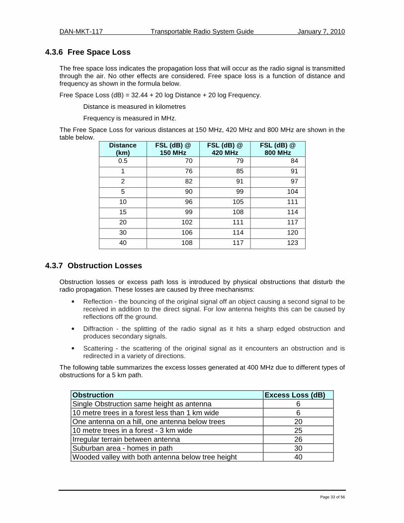
4.3.6 Free Space Loss
The free space loss indicates the propagation loss that will occur as the radio signal is transmitted through the air. No other effects are considered. Free space loss is a function of distance and frequency as shown in the formula below.
Free Space Loss (dB) = 32.44 + 20 log Distance + 20 log Frequency.
Distance is measured in kilometres
Frequency is measured in MHz.
The Free Space Loss for various distances at 150 MHz, 420 MHz and 800 MHz are shown in the table below.
Distance (km)
FSL (dB) @ 150 MHz
FSL (dB) @ 420 MHz
FSL (dB) @ 800 MHz
0.5 70 79 84
1 76 85 91
2 82 91 97
5 90 99 104
10 96 105 111
15 99 108 114
20 102 111 117
30 106 114 120
40 108 117 123
4.3.7 Obstruction Losses
Obstruction losses or excess path loss is introduced by physical obstructions that disturb the radio propagation. These losses are caused by three mechanisms:
• Reflection - the bouncing of the original signal off an object causing a second signal to be received in addition to the direct signal. For low antenna heights this can be caused by reflections off the ground.
• Diffraction - the splitting of the radio signal as it hits a sharp edged obstruction and produces secondary signals.
• Scattering - the scattering of the original signal as it encounters an obstruction and is redirected in a variety of directions.
The following table summarizes the excess losses generated at 400 MHz due to different types of obstructions for a 5 km path.
Obstruction Excess Loss (dB) Single Obstruction same height as antenna 6 10 metre trees in a forest less than 1 km wide 6 One antenna on a hill, one antenna below trees 20 10 metre trees in a forest - 3 km wide 25 Irregular terrain between antenna 26 Suburban area - homes in path 30 Wooded valley with both antenna below tree height 40

DAN-MKT-117 Transportable Radio System Guide January 7, 2010
Page 34 of 56
4.3.8 Fade Margin
The received signal can vary over time due to varying atmospheric conditions, changes in the path profile resulting in varying reflections, diffractions and scattering. To compensate for these variable effects and to ensure reliable path propagation under all circumstances radio planners introduce a fade margin in the attenuation calculation.
The higher the fade margin the higher the availability of the path under all conditions. A typical fade margin on a Line of Sight path can be as much as 20 - 30 dB.
4.3.9 Path Calculation Worksheet
The following table provides a simple worksheet for calculating the signal gains / losses in an LMR radio system and the resulting margin and range that the system could provide.
RF System Gain Calculation Value dB
A Handheld Transmitter 5 Watts 37
B Repeater Receiver 118
C Duplexer Losses -1.5
D Cable Losses -1
E Antenna 1
F Obstructions - trees in a forest -25
G Resulting Margin 126.5
H Desired Fade Margin -20
J Resulting Maximum Free Space Loss (420 MHz UHF) 10 kms 105

DAN-MKT-117 Transportable Radio System Guide January 7, 2010
Page 35 of 56
4.4 Duplexers
4.4.1 Isolation
As explained in Section Two, a portable or mobile subscriber unit makes use of simplex operation which allows it to only receive or transmit a signal, but not both simultaneously. This is accomplished through the use of an antenna relay that allows the RX to be connected when the radio is receiving signal. When the operator of the radio presses the Push-to-Talk (PTT) button to transmit a message back, the relay switches over thus disconnecting the receiver and connecting the transmitter to the antenna.
�������
�� ��
�������
�� ��
������ � ����� ���������� � �����
�������� ��� ������ ��������
��������� �� ����� ���� ��� ��������
��
When we then look at the operation of the Repeater, we can see the difference between simplex and duplex operation. When a repeater is active, it is both receiving and transmitting signals at the same time. The signal that is being broadcast by the transmitter will always be MUCH stronger than the incoming receive signal due to the proximity of the transmitter to the receiver. Because of this, the receiver needs to be isolated from the transmitter to prevent the strong transmitter signal from interfering with the far weaker incoming signal.
The most important part in creating this isolation is that the transmitter frequency must be different from the receiver frequency. The greater the difference between the two frequencies, the less likely the transmit signal will interfere with the receiver. For example, if the receiver frequency is only 500 kHz away from the transmit frequency, this system will need much more isolation than a system where the receiver frequency is 5 MHz away from the transmit frequency.
Isolation is measured in dB and every repeater will have a particular isolation requirement that is based on a number of factors which include:
• Transmitter Power Output • Difference in RX and TX frequencies • Frequency Band • Selectivity of the receiver
Antenna
TX RX
Outgoin
g sign
al
Repeater Duplex Operation
Repeater in operation – Radio Receives and Transmits at the same time
“Isolation”
Incoming signal

DAN-MKT-117 Transportable Radio System Guide January 7, 2010
Page 36 of 56
4.4.2 How do I provide isolation to the repeater?
The simplest method of creating isolation between a transmitter and a receiver is to use two separate antennas. Based on the isolation requirements of the repeater at the frequencies it is set for, the antennas must then be physically separated in either horizontal or vertical distance. The following graphs show the relative isolation that is achieved in the different frequency bands based on the distance between the transmit and receive antennas.

DAN-MKT-117 Transportable Radio System Guide January 7, 2010
Page 37 of 56
A transportable VHF repeater is deployed with a transmitter frequency of 155.3125 MHz and a receiver frequency of 155.8125 MHz. The difference between these two frequencies is 500 kHz. It is known that this particular repeater requires isolation between the transmitter and the receiver equal to 85 dB to avoid any desensitization of the receiver. How much vertical and horizontal distance is required between the two antennas to achieve this isolation?
If the two antennas can be mounted 100 feet apart from each other horizontally, the graph tells us that this will give approximately 42 dB of isolation. The remaining 43 dB of isolation will need to be made up by separating the two antennas vertically as well. To achieve the remaining 43 dB of isolation, the vertical separation graph shows that approximately 16 feet of vertical separation will give 43 dB of isolation. Ultimately this will mean that the repeater will have one antenna located on the ground beside the repeater, and a second antenna located 100 feet away and suspended 16 feet above the ground on some kind of mount. While this achieves the desired results, it often is a challenge to deploy a Transportable Radio with these kinds of set up constraints.
4.4.3 Duplexer Characteristics
The simpler alternative to using two antennas is to use a duplexer and a single antenna. This makes the deployment requirements for the repeater much simpler, but it also comes with some trade-offs.
First and most importantly, the biggest difference between using a duplexer and two antennas is channel bandwidth. For a duplexer to achieve the high level of isolation, it sacrifices the ability to have a wide channel range. Most small, portable duplexers in fact are tuned only for a single frequency pair which means that the repeater can only be used on that one channel and no other. The two antenna system allows for much wider channel capability.
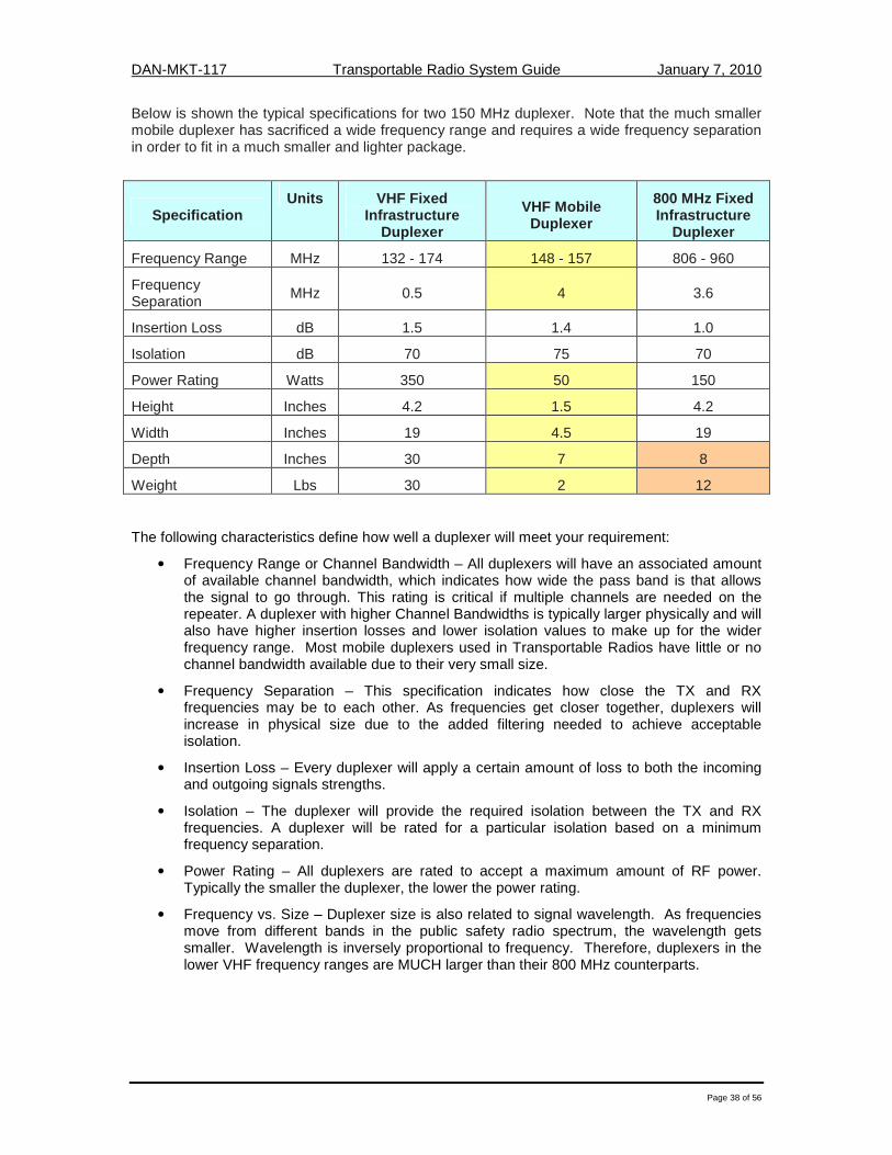
DAN-MKT-117 Transportable Radio System Guide January 7, 2010
Page 38 of 56
Below is shown the typical specifications for two 150 MHz duplexer. Note that the much smaller mobile duplexer has sacrificed a wide frequency range and requires a wide frequency separation in order to fit in a much smaller and lighter package.
Specification Units VHF Fixed
Infrastructure Duplexer
VHF Mobile Duplexer
800 MHz Fixed Infrastructure
Duplexer
Frequency Range MHz 132 - 174 148 - 157 806 - 960
Frequency Separation MHz 0.5 4 3.6
Insertion Loss dB 1.5 1.4 1.0
Isolation dB 70 75 70
Power Rating Watts 350 50 150
Height Inches 4.2 1.5 4.2
Width Inches 19 4.5 19
Depth Inches 30 7 8
Weight Lbs 30 2 12
The following characteristics define how well a duplexer will meet your requirement:
• Frequency Range or Channel Bandwidth – All duplexers will have an associated amount of available channel bandwidth, which indicates how wide the pass band is that allows the signal to go through. This rating is critical if multiple channels are needed on the repeater. A duplexer with higher Channel Bandwidths is typically larger physically and will also have higher insertion losses and lower isolation values to make up for the wider frequency range. Most mobile duplexers used in Transportable Radios have little or no channel bandwidth available due to their very small size.
• Frequency Separation – This specification indicates how close the TX and RX frequencies may be to each other. As frequencies get closer together, duplexers will increase in physical size due to the added filtering needed to achieve acceptable isolation.
• Insertion Loss – Every duplexer will apply a certain amount of loss to both the incoming and outgoing signals strengths.
• Isolation – The duplexer will provide the required isolation between the TX and RX frequencies. A duplexer will be rated for a particular isolation based on a minimum frequency separation.
• Power Rating – All duplexers are rated to accept a maximum amount of RF power. Typically the smaller the duplexer, the lower the power rating.
• Frequency vs. Size – Duplexer size is also related to signal wavelength. As frequencies move from different bands in the public safety radio spectrum, the wavelength gets smaller. Wavelength is inversely proportional to frequency. Therefore, duplexers in the lower VHF frequency ranges are MUCH larger than their 800 MHz counterparts.

DAN-MKT-117 Transportable Radio System Guide January 7, 2010
Page 39 of 56
4.5 Antennas
Antennas are manufactured to operate on a specific frequency and should not be altered in any way. There are three factors of practical importance in the design of an antenna. These are:
• Antenna gain
• Radiation pattern.
• Physical size / construction
Shown to the right is a rugged collapsible aluminum antenna mast tripod which is ideal for rapid deployment. The mast is supplied with a duffle bag with wheels, all necessary tools, pegs and guy wires. Various heights are available from 2 to 15 metres (6 to 49 feet).
4.5.1 Radiation Patterns and Types
A wide variety of antennas exist to meet different requirements. The photo above illustrates two of the more common antenna types on the market. On the left is an omni directional 5/8 wavelength monopole and on the right is directional Yagi.�
4.5.1.1 1/4 Wavelength
A quarter wavelength antenna is the simplest of all antenna types. In the 400 MHz band for example it is a very short (25 cm) monopole antenna. This antenna typically has no gain and is omni directional in nature. The antenna requires a ground plane for proper operation which is typically 1 wavelength square (approximately 1 square metre at this frequency).
4.5.1.2 5/8 Wavelength
A 5/8 Wavelength Antenna in the 400 MHz band is a 53 cm long monopole antenna. This antenna typically has low gain (1 - 2 dB) and is Omni directional in nature. An example is shown above to the left.
4.5.1.3 Yagi
A YAGI Antenna is still common on most rural rooftops for TV reception. In the LMR frequency bands (UHF and VHF) the antenna is quite large with an area of several square metres. This antenna typically has good gain (7 - 8 dB) and is directional in nature. The size of this antenna dictates a rooftop installation. A significant disadvantage of the YAGI antenna is the exposed elements of the antenna can create sizeable wind and ice loading. The directionality of the antenna can also change dramatically under icing conditions. An example is shown above to the right.
4.5.1.4 Omni Directional
An Omni directional antenna is used when the transmitter is located in the center of the desired coverage area. This type of antenna is widely available at all frequencies. A maximum gain in the range of 12 dBi is possible.

DAN-MKT-117 Transportable Radio System Guide January 7, 2010
Page 40 of 56
4.5.1.5 Portable Antenna
LMR systems also include mobiles and portables, for which the most common antennas are the “whip” and “rubber-duck” respectively. Remember that these antennas are also manufactured for use on a specific frequency or a narrow band of frequencies. These antennas are a compromise and provide little or no gain to the signal from the transmitter. Depending on the degree of compromise, they may even show a loss.
4.5.2 Antenna Size and Characteristics
The physical size and construction of the antenna becomes important when you consider the type of housing and antenna mounting that you will require for your repeater, which in turn is determined by the weather conditions at your chosen site and the amount of antenna gain your calculations show that you will require.
The gain, shown in dB on the manufacturer’s data sheet, is determined by the construction. However, a gain in one direction is accompanied by a loss in another direction. Remember when using high gain antennas that the higher the gain, the smaller the cross-sectional area of the radiation pattern. This is an advantage in links as it reduces the chance of multiple paths caused by reflections and is a disadvantage on drops as it will leave near-field shadows.
Directional antennas also have the following characteristics - Front to back gain ratio greater than 10:1. All antenna data sheets provide a gain pattern showing the amount of gain provided as a function of the angle. This is usually referred to as a pattern or polar plot and can be provided both for the horizontal as well as vertical orientations. The graph below illustrates a typical directional antenna with a 170° horizontal pattern.
Any antenna that you purchase for use on a repeater system will have a nominal impedance of 50 ohms. A VSWR of 1.5:1.0 or less over the frequency range is adequate for transportable purposes.

DAN-MKT-117 Transportable Radio System Guide January 7, 2010
Page 41 of 56
4.5.3 Practical Considerations for your antenna
When considering antenna placement think about the antennas that you will be using and watch for surfaces on either side of the path that may reflect minor antenna lobes. Watch for near field obstructions when determining antenna placement.
Where climatic extremes are anticipated, heavy duty models may be necessary. In addition, antennas are manufactured for a rated wind velocity and also for a rated wind velocity with one-half inch of radial ice load. Ensure that your site conditions are within these limitations. Other factors to consider include:
• Mounting – How will you mount the antenna?
• Masts – Can you use a mast?
• Magnetic-Mounts – will it mount on a metal surface?
• Ground Planes – Does the antenna require a large metal flat surface to act as a ground plane?
• Placement – where will the antenna be placed during the deployment? Is stealth a requirement?
• Construction/Environmental considerations – How robust does the antenna and mast need to be for your application?
• Icing – Is this an issue?
• Wind – Can the wind tip it over?

DAN-MKT-117 Transportable Radio System Guide January 7, 2010
Page 42 of 56
4.6 Enclosures – Choosing the right case
Depending on the nature of a typical deployment for your Transportable Radio, the enclosure can be critical to the success or failure of your system. The following factors should be considered when selecting the type of case that is best for your application.
• Weather – Will the system be exposed to rain, dust or icing? If so then a full weatherproof enclosure will be required.
• Altitude – if the case is being transported in a plane or helicopter, a pressure relief valve is needed to deal with air pressure changes that could explode the case.
• Vandalism – Will the case be located in an area where vandalism or theft is a concern? If so secure locking mechanisms are required.
• Stealth or High Visibility – Does the application have a requirement for a case that is stealthy and unnoticed by the public? Conversely is the case being located in a remote area where it is desirable to have a high visibility case that can be easily located for retrieval?
• Heating due to Sun exposure – Does the colour of the case matter to minimize heating due to exposure to the sun (black versus yellow)?
• Diplomatic Package – If the case is being used by diplomats then an orange case can simplify international shipping and bypass customs.
• Wheels – Will the case be used in an area where wheels will make it easier to move the case?
• Handles – Are the carrying handles suitable for single person lifting, multiple person lifting or transport via machines or pack animals?
• Internal / External Connectors – Does it matter if the connectors are internal or external?
• Internal Battery – Does the case need an internal battery or external battery?
• Smooth Surface – Does the case have smooth surfaces so it won’t tear upholstery in a car during transport or rip loose a connector if it slides around in the back of a pickup?
4.6.1 Open/Closed Lid Operation
The one major benefit of deploying a system capable of closed-lid operation is that the system may be deployed in a much broader set of environmental situations. Assuming the case is rated for all weather conditions; it can be left outside, exposed to rain or snow and has locking mechanisms to prevent theft or vandalism.
Applications where open lid operation is beneficial include: • Controlled environment to allow ventilation of internal heat created by radio • Easier connection of AC power supplies and reduced cost of expensive bulkhead
connectors • Allows for more discrete deployments as cases can be made to look like standard
luggage vs. electronic equipment covered in connectors.

DAN-MKT-117 Transportable Radio System Guide January 7, 2010
Page 43 of 56
4.6.2 Case Selection
There are a variety of enclosures available on the market, each with its own unique features:
• Aluminum Cases – Typically these cases are very rugged and
capable of air-tight ratings for the harshest of wet environments. These cases are also a good option for outdoor deployments such as forest fire fighting or search and rescue. Secure locking mechanisms can also be provided.
• Polyethylene Cases – There are a large number of vendors providing
polyethylene suitcases and briefcases in every size and colour imaginable. There are a variety of options available with these cases including: pull-out handles and roller wheels. Ideal for sub-urban and urban deployments.
• Polyethylene Rack Mount Cases – Larger versions of the polyethylene suitcases. These
cases typically have entire racks inside for mounting of larger communications systems such as multi-agency/multi-band systems or Transportable Trunked systems with multiple channels. Typically they are for very heavy equipment and require more than one person to lift. Ideal for permanent mounting inside vehicles or mobile command centers.

DAN-MKT-117 Transportable Radio System Guide January 7, 2010
Page 44 of 56
4.6.3 Weight
The selection of the case may be determined by its weight or conversely the application it is intended for may dictate the maximum weight of the case. Shown below is a recommended lifting weight range from the UK government http://www.hse.gov.uk/pubns/indg143.pdf
Note: 1 kg = 2.21 Pounds (lbs)
Each box contains a guideline weight for lifting and lowering in that zone. The guideline weights are reduced if handling is done with arms extended, or at high or low levels, as that is where injuries are most likely to occur. The guideline weights assume that the load is readily grasped with both hands and that the operation takes place in reasonable working conditions, with the lifter in a stable body position.

DAN-MKT-117 Transportable Radio System Guide January 7, 2010
Page 45 of 56
4.6.4 Case Size Selection
The requirements of the system may necessitate that some components are large and cumbersome. A common situation that can cause this is frequency selection/availability for the repeater. Many times the user of the repeater does not have much choice regarding the channels they can use in their system. This may ultimately mean that the frequencies are very close and the system requires a large duplexer. If the duplexer needed to satisfy the system requirements is too large for the main repeater case, then a second case can be used to contain the duplexer. In these scenarios, it is wise to consider once again how and where the system will actually be deployed. If the system needs to be loaded into a small helicopter, or needs to be hand carried up multiple flights of stairs, then multiple smaller boxes might be much easier to handle vs. a single large box that may require multiple personnel to lift.
Other scenarios that can affect case size/weight include:
• Vehicle mounted repeaters – Size can get quite large for these repeater solutions however actual location of the deployment on-scene is limited to vehicle access areas.
• Man-Pack deployments – Some agencies must operate in ever-changing environments such as large scale tracking through urban areas on foot (shopping centers for example). These deployments may require one person to carry the repeater inside a back-pack or case during operation. This creates a moving radio coverage area that can be quite effective in challenging RF environments. Obviously size/weight is of the upmost importance for this deployment scenario.
• Briefcase/Suitcase – For transportation simplicity, it can be beneficial that the repeater fit into a standard form factor for travel such as a briefcase or suitcase. Briefcase options can allow for discrete deployments of the repeater. Suitcase options can allow for larger systems to be transported with relative ease as roller wheels and other common luggage features are typically employed.
• 2-Man Lift – Many large Transportable Radio options are designed more with simplicity in mind. A single case that can be deployed on-scene, with little or no further connections needing to be made. The trade-off with this however is that quite often the single case can become quite heavy.

DAN-MKT-117 Transportable Radio System Guide January 7, 2010
Page 46 of 56
4.7 Power Supplies
The final key consideration in selection of the Transportable Radio elements is the power supply. How are you going to power the repeater? The following sections outline the common power supplies options available for Transportable Radios with their associated trade-offs.
4.7.1 AC AC Power is the simple power option - just plug the repeater into the “wall” and turn it on. This is only appropriate for some applications as even the most urban deployments can find a system with only AC power options very limited in where it can be deployed. Either that or get a very long extension cord… When using AC power as the primary source a number of considerations need to be kept in mind:
• If the system requires AC power, then each time it is deployed, the location selected must be within range of an AC power supply. This may be a problem in some environments.
• Most rural locations will have very limited AC deployment options
• Most electronic equipment runs on DC voltages. If AC power is the only desired source then an AC-DC power supply will need to be included in the repeater system which can add significant weight, size and cost to the system.
• AC power cabling can get complicated when running closed-lid systems. Finding AC bulkhead connectors that maintain the integrity of the power supplies electrical approvals is always challenging.
• Each country in the world has its own set of utility power characteristics. This means that a system that runs correctly in North America will need to be adjusted to run off the utility power in Europe.
• Having the capability to switch input AC frequency and voltage is beneficial, but also requires careful monitoring each and every time the system is powered on. If the wrong input voltage and/or frequency is selected on the equipment, then damage may occur to the equipment.
Using a generator to produce AC power is an option but again there are a number of considerations to bear in mind:
� Generator power may increase the number of scenarios a repeater may be deployed in, but also adds a significant logistical issues into the deployment; fuel.
� Be aware that when using generator power as the sole source, generator maintenance will be a constant issue for those on-scene.
- Noise-Limiting – the noise of a generator will be an obvious giveaway during a stealth operation.
� If a lower-cost generator is being used for the system power, this can quite often introduce “dirty” power into the system. This dirty power is noisy and can wreak havoc on a communications system. Even higher grade generators may experience this problem if they are over-sized or for the load they are carrying. A large generator with a very small load will run far less efficiently than a generator with a maximum load.

DAN-MKT-117 Transportable Radio System Guide January 7, 2010
Page 47 of 56
4.7.2 DC DC Power is the more common power option – connect the repeater to a set of batteries and you are operational anywhere. However, when using DC power as the primary source a number of considerations need to be kept in mind:
• Internal Battery Power – Very simple to operate, just turn on the repeater. However, this comes with a number of trade-offs. Internal batteries mean the repeater is heavier. The repeater will have a shorter run time as only small batteries can be used. Users of the system must always remember to recharge the repeater between uses and the repeater must be very efficient with its current draw.
• External Battery Power – By adding a second case to the repeater system, significant increases in run times can be achieved as the external battery can be much larger than its internal relative. However, a second case is now included in the deployment which adds costs, size and weight to the deployment.
• Solar/Battery Powered – By adding a solar panel to the repeater, it is possible to achieve extremely long run times to the deployment. This is very helpful for deployments that will be for an undetermined amount of time such as a Natural Disaster recovery or Forest Fire Response. This solution adds a third case to the deployment however and the repeater itself needs to be very efficient with its current draw.
• Generators – offer a DC power output, however the need to provide fuel is a major consideration.
4.7.2.1 Solar Power
On a sunny day each square meter of the earth's surface receives about 1 kilowatt of energy (1Kw/m2). A solar cell converts light energy into electrical energy. A cell's current and output are directly proportional to its illuminated area and illumination level. Voltage is unaffected by cell area, and is relatively insensitive to illumination level. Above a low illumination threshold, cell voltage stays constant at around 0.5 VDC. On the other hand current output, and therefore its power, increases in proportion to illumination levels.
With advances in design, the mounting angle is not as critical as it was previously. A useful rule of thumb is to mount your panel at an angle to earth equivalent to your latitude plus five degrees. Remember to point the panel(s) true south, towards the sun at noon.
An example of a transportable solar panel package is shown to the right. Packaged in a compact polyethylene case the solar panel is lightweight, easy to carry and offers either 60 or 120 Watts of power. The Solar panels are rugged, compact and lightweight. They unfold to a size of 6’ x 4’ yet fold up into a package that is the size of a laptop.

DAN-MKT-117 Transportable Radio System Guide January 7, 2010
Page 48 of 56
Using the solar and battery calculation worksheet below it is possible to determine the battery backup and solar panel size required for your Transportable Radio. Values highlighted in yellow are selected based on your application. Grayed values are derived from manufacturer product data.
Assuming a 5 day deployment of a Transportable Radio for a search and rescue application, it is assumed that the radio will be operational 18 hours a day and used 10% of the time. Based on the manufacturer's specifications the receiver draws 0.2 Amps in standby mode and 1.8 Amps when it is transmitting (8 watts RF output). A solar panel will be used to supplement the batteries and in the deployment area there are 10 hours a day of strong sunlight.
Thus the radio will consume 0.2 amps x 24 hours + 1.8 Amps x 10% duty cycle x 18 hours operation = 4.8 Amps + 3.24 Amps = 8.04 Amps daily.
The Solar panels are rated for 60 Watts output or 5 Amps @ 12 Vdc. With 10 hours of sunshine daily they will generate 50 Amps of total current which is more than enough to run the radio and recharge the batteries for nighttime operation.
To ensure continuous operation on batteries for the 5 days we will require a battery bank with a capacity of 8.04 Amps x 5 days = 40 Amp Hours (Ah) without a solar panel to recharge the batteries. If we use a solar panel then the battery requirement is 8 hours (18-10) when the solar panels are not generating power x radio current drain (0.2 + 1.8) = 16 Ah battery capacity.
Solar and Battery Calculation Worksheet Value Unit
A Expected Deployment Duration 5 days
B Daily Operating Duration 18 hours
C Duty Cycle 10%
D Receiver Standby Current .2 Amps
E Daily Standby Current Drain (B x 24) 4.8 Amps
F Active Transmitter Current 1.8 Amps
G Daily Total Transmitter Current Drain (B x C x G) 3.24 Amps
H Total Radio Daily Amp Hour requirement (E + G) 8.04 Amps
J Solar Panel Peak Rating 60 Watts
K Solar Panel Current Rating (J/12) 5 Amps
L Hours of Sunshine Daily 10 hours
M Solar Panel Daily Current Generation (K x L) 50 Ah
N Number of Solar Panels Required (H/M) 1
P Battery Capacity Required (H x A) - No Solar Power 40 Ah
Q Battery Capacity Required ((B-L) x ((D+F)) - With Solar Power 16 Ah

DAN-MKT-117 Transportable Radio System Guide January 7, 2010
Page 49 of 56
4.8 Operation and Maintenance
Having worked your way through all of the factors required to select a transportable radio system to meet your application there is one final set of considerations that need to be addressed: how will the system be used and maintained?
• Setup Skill Level required - During a deployment who is setting up the system – will it be the actual user (police officer or fireman) or the radio technician? Obviously for non radio technicians the system will need to be as simple as possible to connect and operate.
• Setup Time and People required – During the setup how many people will be required to carry the equipment to site and set everything up? Is this a one many deployment or will it require vehicles and 10 people?
• Training – What level of training is expected and provided to the actual users of the system and the people setting it up? Is the system simple enough that anyone can grab it off the shelf and then simply turn on a power switch or do they need a multi day course to configure and operate the system?
• Configuration – Does the system require configuration before each and every deployment or is it ready to operate in most expected scenarios? If configuration is required, who will do it, where and how long will it take?
• Repair – When something breaks (Murphy guarantees it will) how easy is it to fix and are the required spares readily available?

DAN-MKT-117 Transportable Radio System Guide January 7, 2010
Page 50 of 56
5. Appendix - References
5.1 Glossary
• Antenna - An elevated device for radiating and receiving radio waves. It changes electrical currents into electromagnetic radio waves and vice versa.
• Antenna Gain - The increase in power radiated by and / or received by an antenna in a given direction compared to the power radiated in the same direction by a standard omni-directional antenna.
• Antenna Polarization - The orientation of the radiated electric field in relation to the surface of the earth.
• Bandwidth - The amount or portion of the frequency spectrum required to transmit the desired information.
• Beam Antenna - An antenna array that concentrates radio transmission into a narrow directional path or receives radio signals only from a narrow sector of the total horizon.
• Channel - A narrow band of frequencies including the assigned carrier frequency, within which a radio system must operate in order to prevent interference with stations on adjacent channels.
• Decibel (dB) - A unit of relative voltage or power. Roughly the smallest change that the human ear can detect. The decibel is also used to compare relative differences of signal voltages, or power.
• Fade Margin - The difference between the level of the received signal and the receiver threshold. Usually expressed in decibels.
• Frequency Band - A continuous range of frequencies extending between two limiting frequencies. Common frequency bands in two-way radio are 29-50 MHz (low band), 136-174 MHz (VHF or High Band), 406-512 MHz, 806-824 MHz, 851-869 MHz , 869-901 MHz and 935-940 MHz (UHF Bands).
• Frequency Range - A frequency band including the frequencies at which a system is able to transmit, receive or amplify power.
• Fresnel Zone - A measurement of path clearance in terms of the effect at the frequency in question. The First Fresnel Zone is the surface containing every point for which the sum of the distances from that point to the two ends is one-half wavelength longer than the direct end-to-end path.
• Front-To-Back Ratio (F/B) - The ratio between the power radiated in the forward direction from an antenna to that radiated to the rear.
• Insolation - The total solar radiation-direct, diffuse and reflected-received on a surface over a period of time. Usually expressed in kilowatt-hours per square meter .
• Interference - The effects that occur when undesired signals interfere with the reception of a desired signal.
• Line-Of-Sight Distance (L/S) - The straight-line distance from station to station or horizon. This represents the approximate normal transmitting range of stations in the VHF and UHF bands.
• Mobile - Equipment designed for vehicular or portable operation.
• Noise - Interference caused by either internal or external sources.

DAN-MKT-117 Transportable Radio System Guide January 7, 2010
Page 51 of 56
• Path Loss - The reduction or attenuation of signal strength that occurs between the transmitter and receiver.
• Portable Radio - A completely self-contained two-way radio.
• Propagation - The radiation of electromagnetic waves.
• Radio Receiver - A device which amplifies radio frequency signals, separates the intelligence signal from the RF carrier, amplifies it, and converts it back to the original sound waves.
• Radio Interference - Interference caused by the radio waves of a station or stations other than that from which reception is desired.
• Repeater - A radio station that automatically rebroadcasts radio signals that are received on a specific frequency.
• Transceiver - A combination of transmitting and receiving equipment that uses some or all of the components jointly in both transmitting and receiving.
• Transmission Loss - A term used to denote the loss in power during the transmission of energy from one point to another.
• Transmitter - The term applied to the equipment that is used to generate and amplify an RF carrier signal, modulating this carrier signal with intelligence, and then provide output for an antenna to radiate the modulated signal into space.
• Trunk, Trunking - A computer controlled radio system in which many users can share multiple switched repeater equipment while retaining privacy.
• Ultra-High Frequency (UHF) - The portion of the radio spectrum extending from 300 - 3000 MHz. (Commonly thought of as 300 - 1000 MHz)
• Very-High Frequency (VHF) - The portion of the radio spectrum extending from 30 - 300 MHz.
• Yagi - A directional antenna which usually consists of a radiator, a reflector and one or more director elements. This antenna exhibits high gain and moderate front-to-back ratio.
5.2 Reference Documents
The following documents provide additional information on repeaters and radio system planning:
• TG-002-1-0-0 Daniels Electronics Land Mobile Radio Systems • TG-001-2-0-0 Daniels Electronics P25 Radio Systems • LIT-052-1-0-0 Daniels Electronics Trunked Radio Product Information • BC Ministry of Forests http://www.for.gov.bc.ca/his/radio/Overview/overview.htm • Wikipedia http://en.wikipedia.org/wiki/Radio_repeater • DAN-MKT-103 ET-5 Tactical Repeater - ATF Content - limited distribution • National Institute of Justice http://www.ncjrs.gov/pdffiles1/nij/191160.pdf • SafeCom www.safecomprogram.gov

DAN-MKT-117 Transportable Radio System Guide January 7, 2010
Page 52 of 56
5.3 Transportable Radio RFQ Sheet

DAN-MKT-117 Transportable Radio System Guide January 7, 2010
Page 53 of 56
700 – 768 MHz

DAN-MKT-117 Transportable Radio System Guide January 7, 2010
Page 54 of 56

DAN-MKT-117 Transportable Radio System Guide January 7, 2010
Page 55 of 56

DAN-MKT-117 Transportable Radio System Guide January 7, 2010
Page 56 of 56
DAN-MKT-117 V3.0 December 2009