Transport performance and AC loss of superconducting ...
25
Brookhaven Technology Group Transport performance and AC loss of superconducting cables comprised of exfoliated YBCO filaments U.S. DOE Office of Science SBIR Phase I award DE-SC0018737, Phase II award DE- SC0013856 Slowa Solovyov , Saad Rabbani, Zachary Mendelson, and Paul Farrell Brookhaven Technology Group Inc., Stony Brook, NY 11794 Tim Haugan Write-Patterson Air Force Base www.brookhaventech.com CEC-ICMC 2019, Hartford CT, July 21 - 25 2019 1
Transcript of Transport performance and AC loss of superconducting ...

Brookhaven Technology Group
Transport performance and AC loss of superconducting cables comprised of
exfoliated YBCO filaments
U.S. DOE Office of Science SBIR Phase I award DE-SC0018737, Phase II award DE-SC0013856
Slowa Solovyov, Saad Rabbani, Zachary Mendelson, and Paul Farrell
Brookhaven Technology Group Inc., Stony Brook, NY 11794
Tim Haugan
Write-Patterson Air Force Base
www.brookhaventech.com
CEC-ICMC 2019, Hartford CT, July 21 - 25 2019 1

Brookhaven Technology Group
Outline
▪ ExoCable technology
▪ Mini coil test results: 77 K and 25 K
▪ AC loss: effect of transposition
▪ Flux dynamics at 25 K
▪ Conclusion and future work
CEC-ICMC 2019, Hartford CT, July 21 - 25 2019 2

Brookhaven Technology Group
Motivation: we need defect tolerant cable
CEC-ICMC 2019, Hartford CT, July 21 - 25 20193
Across-tape defects
Along-tape defects
Deposition malfunction
Epitaxy failure
Some defects emergeduring coil operation
Courtesy of Anatolii PolyanskiiNHMFL
✓ Avoiding defects in YBCO layers is difficult
✓ Some defects are hidden, get revealed only after coil tests

Brookhaven Technology Group
Solution: electrically coupled cable
2G wire stack BTG exfoliated filament stack
Buffer
Substrate
Sharing current path
Sharing current path
CEC-ICMC 2019, Hartford CT, July 21 - 25 2019 4
We are solving the following problems:▪ Single-filament magnets proven difficult to protect against burnout
▪ Substrate prevents efficient current sharing
▪ Multifilamentary cable is far more expensive than a single tape
▪ Not compatible with epoxy impregnation

Brookhaven Technology Group
BTG filament, two directions for current sharing
CEC-ICMC 2019, Hartford CT, July 21 - 25 2019 5
YBCO, Ag layer, 1.2 µm
Solder 10 µm
Copper 75 µm
Solder 5 µm
Current sharing directions
✓ The filament stack is YBCO-metal composite

Brookhaven Technology Group
Multi-filamentary cable architecture
CEC-ICMC 2019, Hartford CT, July 21 - 25 2019 6
Copper stabilizerNichrome cladding Solder YBCO
✓ Electrically connected filaments are the key element

Brookhaven Technology Group
Current transfer after the re-flow step
CEC-ICMC 2019, Hartford CT, July 21 - 25 2019 7
✓ Exfoliated stack enables current sharing within < 5 mm
10-7
10-6
10-5
10-4
10-3
60 65 70 75 80 85 90 95 10010
-7
10-6
10-5
10-4
10-3
Vo
lta
ge, (
V)
Current, I (A)
160 165 170 175 180 185 190 195 200-0.8
-0.7
-0.6
-0.5
-0.4
-0.3
-0.2
-0.1
0.0
0.1
0.2
Solder coated
filament
He
at f
low
, F (
W/g
)
Temperature, T (oC)
Un-coated filament, signal x100
Solder re-flow
temperature
0 20 40 60 80 10010
2
103
104
105
106
107
180oC
185oC
190oC
Inte
r-fi
lam
en
t re
sist
ivit
y,
(n
·c
m2)
Re-flow duration, t (min)
Re-flow temperature:
Before reflow
After reflow
1 cm
8 cm
Calorimetry Optimization of the resistance
1 cm
8 cm
Brookhaven Technology Group
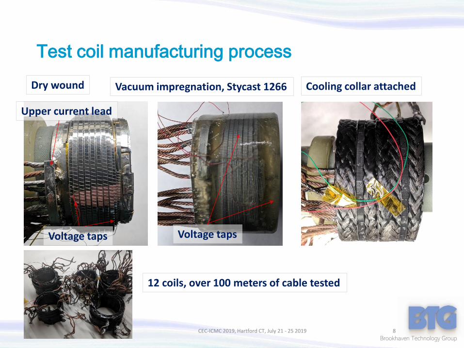
Test coil manufacturing process
CEC-ICMC 2019, Hartford CT, July 21 - 25 2019 8
Dry wound Vacuum impregnation, Stycast 1266
Upper current lead
Voltage taps Voltage taps
Cooling collar attached
12 coils, over 100 meters of cable tested

Brookhaven Technology Group
77 K performance after re-flow and impregnation
CEC-ICMC 2019, Hartford CT, July 21 - 25 2019 9
✓No Ic and n-value degradation after multiple rapid cool-downs to 77 K
✓Solder reflow significantly reduces the winding noise, but reduces Ic by 8%
1 2 3 4 5 6 7 8 9 100
100
200
300
400
500
C5, onel layer, W14
C3, six layers
C3, one layer
C1, one layer
Cri
tica
l cu
rre
nt,
Ic (
A)
Number of cycles, room temperature - 77 K
C2, three layers
0.2
0.4
0.6
0.8
1.0
0 100 200 300 400 5000.0
0.5
1.0
1.5
2.0
10-7
V/m
10-6
V/cm
10-7
V/m
10-6
V/cm
Solder re-flow
Three layer coil I20
Epoxy-impregnation
As-wound
Solder re-flow
Six layer coil I17
Epoxy-impregnation
Vo
ltag
e, V
(m
V)
Applied current, I (A)
As-wound
Cycling RT to 77 K

Brookhaven Technology Group
AC loss: Simplified flux penetration model into a coupled cable, highly anisotropic filament
CEC-ICMC 2019, Hartford CT, July 21 - 25 2019 10
Cross-filament loop (coupling currents)Cross-filament dipole
Persistent current loop (in-plane currents)In-plane dipole (same as in pancakes)
Radial field, Hr
Axial field, Ha
Solenoidal field Hs
In-plane dipoleShields Hr
Subtracts from Hs
Cross-filament dipoleShields Ha shields in the windingAdds to Hs in the bore

Brookhaven Technology Group
High field AC loss and field error (winding magnetization)un-transposed (flat cables) cables
CEC-ICMC 2019, Hartford CT, July 21 - 25 2019 11
0 1 2 3 4 5 6 7 8 9 10 11 12 130.0
0.2
0.4
0.6
0.8
2.4 mm BTG cable
4 mm SP tape stack
Loss
at
10
0 H
z, E
l(W/m
A c
ycle
)
Cable width (mm)
12 mm SP tape
0 20 40 60 80 100 120 1400
20
40
60
80
100
Fused stack
Loss
, (W
/m)
Frequency, Hz
0.59 T
Wraped stack
0.6 Tesla AC loss measurement
✓ AC los and field error is reduced proportionally to the filament width
0 50 100 150 2000.0
0.1
0.2
0.3
0.4
0.5
Coil current (A)
3d cycle
2nd cycle
Ma
gne
tic
fie
ld h
yste
resi
s,
0H
(m
T)
1st cycle
0 50 100 150 2000.000
0.005
0.010
0.015
0.020
0.025
0.030
C3, six layers
C1, one layer
C2, three layers
No
rmal
ize
d h
yste
resi
s,
H/H
ma
x
Coil current, I (A)
Double pancake
12 mm tape

Brookhaven Technology Group
Effect of transposition on AC loss
CEC-ICMC 2019, Hartford CT, July 21 - 25 2019 12
0 20 40 60 80 100 120 1400.0
0.1
0.2
0.3
0.4
0.5
0.6
4 filaments, flat
AC
loss
(J/
cycl
e/m
)
Frequency (Hz)
4 filaments, spiral
0.6 Tesla, 77 K
0 20 40 60 80 100 1200.0
0.1
0.2
0.3
0.4
1.5 mm flat
1.5 mm twisted, 40 mmAC
loss
(J/
cycl
e/m
)Frequency (Hz)
0.6 Tesla, 77 K calorimetry
✓ Transposition does reduce AC loss significantly✓ Filament width is the most important factor

Brookhaven Technology Group
Magnetization hysteresis in flat and twisted cable test coils
CEC-ICMC 2019, Hartford CT, July 21 - 25 2019 13
0 20 40 60 800.00
0.01
0.02
0.03
0.04
0.05
0.06
0.07
3d cycle, flat
1st cycle, twisted
3d cycle
twistedHysteresis
Hys
tere
sis,
H
(m
T)
Current, I (A)
Trapped field
1st cycle, flat
✓ At 35 mm pitch twisting resulted in an insignificant reduction of hysteresis

Brookhaven Technology Group
25 K testing-conduction cooled
CEC-ICMC 2019, Hartford CT, July 21 - 25 2019 14
12” chamber Cryomech compressor Cryomech coldhead
Mounted coilWith scanning Hall probe

Brookhaven Technology Group
Central field hysteresis at 77 and 25 K
CEC-ICMC 2019, Hartford CT, July 21 - 25 2019 15
0.0
0.1
0.2
0.3
0.4
0.5
0.6
0 200 400 600 800 1000 1200
-40
-20
0
20
Ce
nte
r fi
eld
,
0H
(T) 22 K, C3, 6 layer coil
4 A/s
Relaxation
Fie
ld h
yste
resi
s,
0H
(m
T)
Coil current, Icoil
(A)
77 K 22 K
✓At 22 K field dynamics is defined by relaxation at high currents

Brookhaven Technology Group
Flux dynamics at 77 and 25 K
CEC-ICMC 2019, Hartford CT, July 21 - 25 2019 16
0 200 400 600 800 1000 1200 14001.000
1.001
1.002
1.003
1.004
1.005
1.006
50 A (0.02 T)
100 A (0.05 T)
No
rmal
ize
d f
ield
, H
(t)/
H(0
) (a
.u.)
Time(s)
6 layer coil, 77 K 200 A (0.10 T)
0 1000 2000 3000 4000 5000 60000.0
0.2
0.4
0.6
0.8
1.0
Coil center, 1,000 A
Decay rate, 300 A
Coil outer edge, 300 A
Coil center, 300 A
No
rma
lize
d f
ield
, H(t
)/H
(0) (
a.u
.)
Time (s)
6 layer coil, 25 K
0
2
4
6
8
10 Field
time
de
rivative
H
/t/H
(10
-5/s)
77 K 25 K
✓Completely different field settling profile at 77 and 25 K.

Brookhaven Technology Group
Time profile of magnetic field inside and outside the bore
CEC-ICMC 2019, Hartford CT, July 21 - 25 2019 17
0 100 200 300 400 500 600
0.8
1.0
1.2
1.4
1.6
1.8
2.0
Radial component, innner
Axial component, innner
Radial component, outer
Axial component, outer
No
rma
lize
d m
agn
eti
c fi
eld
, (a
.u.)
Time (s)
Relaxation at 300 A
Magnet axis
✓The central field reduction is probably explained by the flux diffusion through the
winding, due to heating from the leads at high current

Brookhaven Technology Group
Heat migration from the current leads and effect on the field quality
CEC-ICMC 2019, Hartford CT, July 21 - 25 2019 18
Current leads
Nichrome heater
0 1000 2000 3000 40000.015
0.016
0.017
0.018
0.019
0.020C1 single layer coil
Fie
ld (
T)
Time (s)
0
10
20
30
40
50
60
70
80
90
Te
mp
era
ture
(K)
✓Winding temperature gradient are responsible for the field decay
Thermocouple

Brookhaven Technology Group
Challenge of conduction-cooled Wiedemann-Franz current leads
CEC-ICMC 2019, Hartford CT, July 21 - 25 2019 19
0 5 10 15 20 25 300
50
100
150
200
1,000 A
600 A
300 A
100 A
1 m long lead, 20 K
0 A
He
at f
lux
at c
old
pla
te, P
(W)
Lead diameter, d(mm)
✓Limited thermal budget of a conduction-cooled magnet complicates high-current lead design

Brookhaven Technology Group
Proposed cryocooled rectifier
CEC-ICMC 2019, Hartford CT, July 21 - 25 2019 20
Transformer Rectifier Magnet coil
Cryogenicenvironment
Low voltage, high current leadsHigh voltage, low current leads
Vacuum vessel
AC power
Cryogenicenvironment
Vacuum vesselTraditionalapproach
Proposed Cryo-cooledrectifier

Brookhaven Technology Group
Mechanical design of the current management system
CEC-ICMC 2019, Hartford CT, July 21 - 25 2019 21
17 KM1
M3
Ls1
Cryo-head
Insulation
RT

Brookhaven Technology Group
Parallel connection of the rectifying elements allows reducing the conduction loss
CEC-ICMC 2019, Hartford CT, July 21 - 25 2019 22
0 50 100 150 200 250 3000
20
40
60
80
4, 130
3, 170
2, 240
Vo
ltag
e d
rop
on
th
e r
ect
ifye
r (V
)
Load current (A)
1, 520
Room temperature
1 2 3 4
100
200
300
400
500
600
Re
sist
ance
pe
r M
OSF
ET (
)
Number of MOSFETs

Brookhaven Technology Group
0 50 100 150 200 2500
10
20
30
40
50
60 18 K, 2 KHz operation
Half-period at 2 KHz
100 A
150 A
300 A
Inp
ut
po
we
r, P
i (W
)
Discharge time, td (s)
28 W
Recovery of energy stored in the dissipation inductance
IBM Seminar May 9 2019, Yorktown NY 23
-50 0 50 100 150 200
0.0
2.0
4.0
6.0
8.0
Incomplete discharge
Discharge gate signal /10
M1
M2Vo
ltag
e (
V)
Time (s)
Coil
-50 0 50 100 150 200
0.0
2.0
4.0
6.0
8.0Discharge gate signal /10
M1
M2Vo
ltag
e (
V)
Time (s)
Coil
Incomplete discharge
Complete discharge
✓ Energy recovery improves efficiency of the drive

Brookhaven Technology Group
Future development: continuous cabling system development
CEC-ICMC 2019, Hartford CT, July 21 - 25 2019 24
Proposed Phase II development
Sequential slicing
Cabling from multiple spoolsFeed spool
Cable spool
Filament spoolFilament spool
Tape spool
✓ Direct cabling from a wide tape spool

Brookhaven Technology Group
Conclusion and future challenges
▪ Conclusion: ▪ Demonstrated operation of epoxy-impregnated multi-filamentary
cable in conduction cooled mode
▪ AC loss is not affected by transposition
▪ Winding magnetization at 25 K is strongly affected by thermal flux, for example from current leads
▪Future challenges▪ Filament fusion: we need < 100 n cm2 areal resistivity
▪ Scale-up of the filament handling
▪ Continuous splicing
CEC-ICMC 2019, Hartford CT, July 21 - 25 2019 25