Transport 2 Ch 1
16
PROBLEM 1.4 KNOWN: Dimensions, thermal conductivity and surface temperatures of a concrete slab. Efficiency of gas furnace and cost of natural gas. FIND: Daily cost of heat loss. SCHEMATIC: ASSUMPTIONS: (1) Steady state, (2) One-dimensional conduction, (3) Constant properties. ANALYSIS: The rate of heat loss by conduction through the slab is q= k (LW) ଵ ଶ ௧ =1.4W/m K(11m *8m) Ԩ .ଶ =4312 W The daily cost of natural gas that must be combusted to compensate for the heat loss is C d = ఎ (Δt) = ସଷଵଶ୵ൈ$.ଶ/ .ଽൈଵ ల / (24h/dൈ3600s/h)=$8.28/d COMMENTS: The loss could be reduced by installing a floor covering with a layer of insulation between it and the concrete.
-
Upload
andrew-horowitz -
Category
Documents
-
view
219 -
download
0
description
some hw answers
Transcript of Transport 2 Ch 1
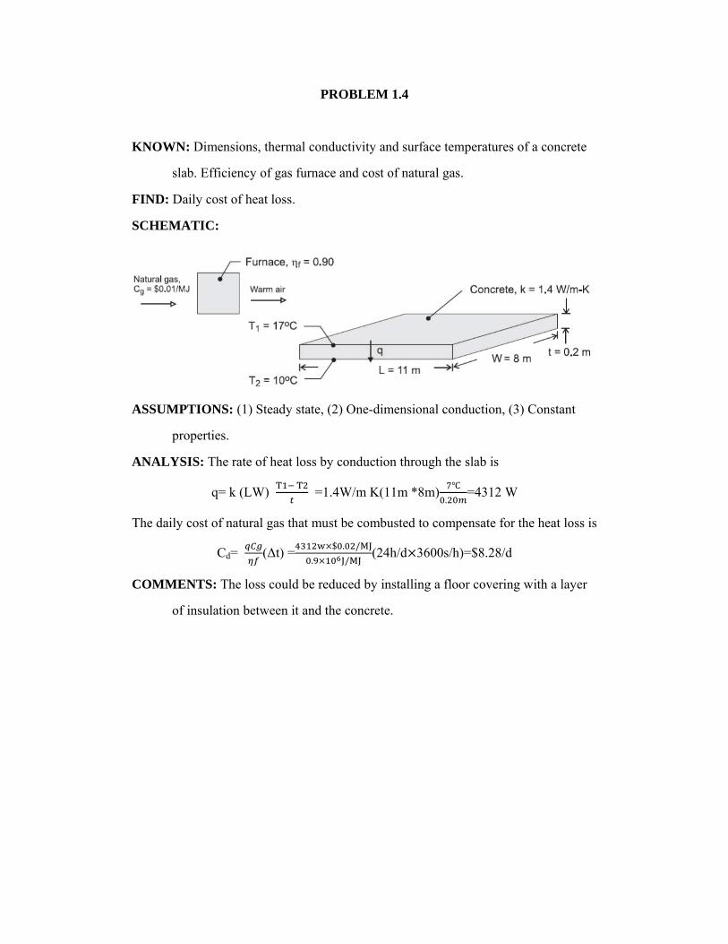
PROBLEM 1.4
KNOWN: Dimensions, thermal conductivity and surface temperatures of a concrete
slab. Efficiency of gas furnace and cost of natural gas.
FIND: Daily cost of heat loss.
SCHEMATIC:
ASSUMPTIONS: (1) Steady state, (2) One-dimensional conduction, (3) Constant
properties.
ANALYSIS: The rate of heat loss by conduction through the slab is
q= k (LW)
=1.4W/m K(11m *8m).
=4312 W
The daily cost of natural gas that must be combusted to compensate for the heat loss is
Cd= (Δt) =$ . /
. /(24h/d 3600s/h)=$8.28/d
COMMENTS: The loss could be reduced by installing a floor covering with a layer
of insulation between it and the concrete.
PROBLEM 1.9
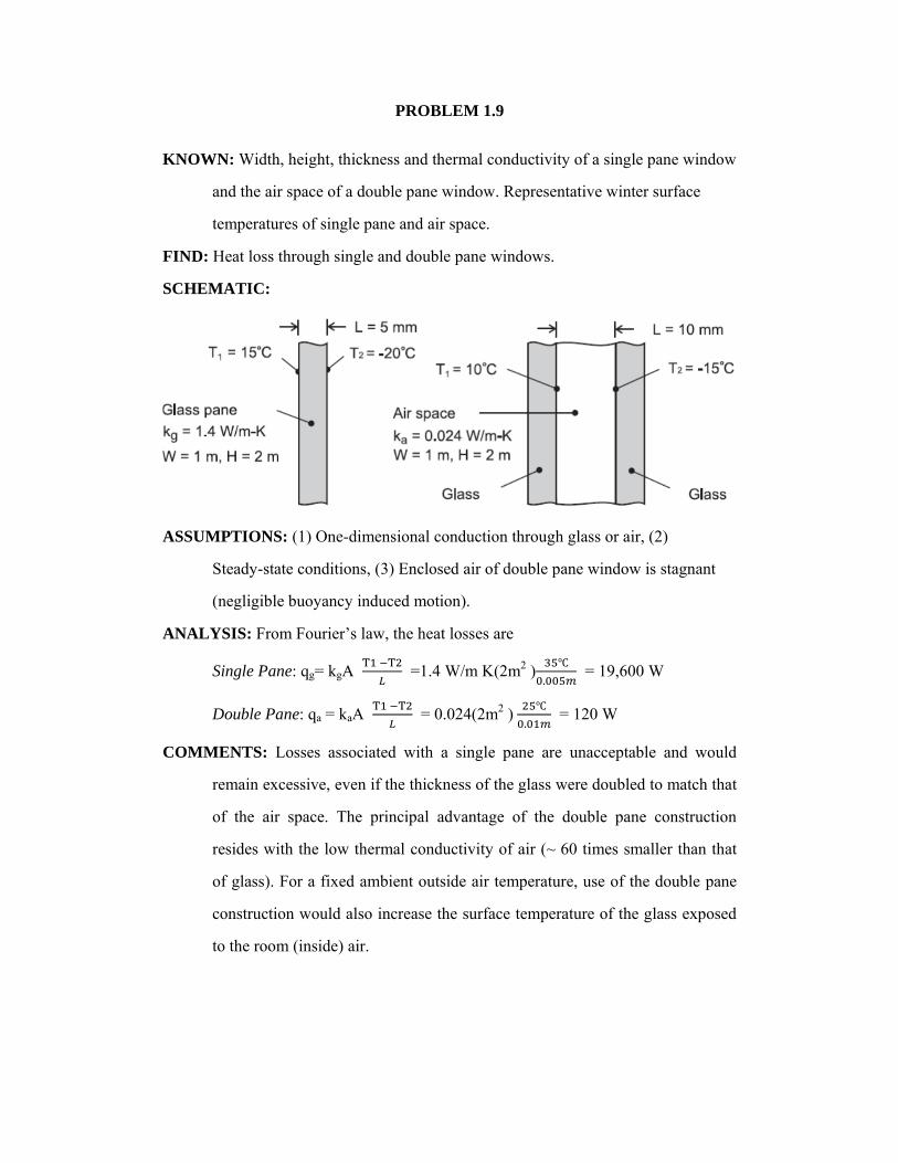
KNOWN: Width, height, thickness and thermal conductivity of a single pane window
and the air space of a double pane window. Representative winter surface
temperatures of single pane and air space.
FIND: Heat loss through single and double pane windows.
SCHEMATIC:
ASSUMPTIONS: (1) One-dimensional conduction through glass or air, (2)
Steady-state conditions, (3) Enclosed air of double pane window is stagnant
(negligible buoyancy induced motion).
ANALYSIS: From Fourier’s law, the heat losses are
Single Pane: qg= kgA
=1.4 W/m K(2m2 ).
= 19,600 W
Double Pane: qa = kaA
= 0.024(2m2 ).
= 120 W
COMMENTS: Losses associated with a single pane are unacceptable and would
remain excessive, even if the thickness of the glass were doubled to match that
of the air space. The principal advantage of the double pane construction
resides with the low thermal conductivity of air (~ 60 times smaller than that
of glass). For a fixed ambient outside air temperature, use of the double pane
construction would also increase the surface temperature of the glass exposed
to the room (inside) air.
PROBLEM 1.15
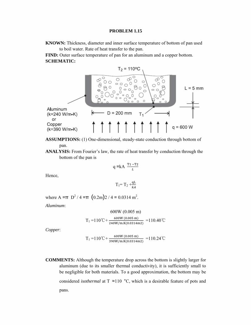
KNOWN: Thickness, diameter and inner surface temperature of bottom of pan used to boil water. Rate of heat transfer to the pan.
FIND: Outer surface temperature of pan for an aluminum and a copper bottom. SCHEMATIC:
ASSUMPTIONS: (1) One-dimensional, steady-state conduction through bottom of
pan. ANALYSIS: From Fourier’s law, the rate of heat transfer by conduction through the
bottom of the pan is
q =kA
Hence,
T1= T2 +
where A =π D2 / 4 =π (0.2m)2 / 4 = 0.0314 m2.
Aluminum: 600W (0.005 m)
T1 =110℃+ .
/ . . =110.40℃
Copper:
T1 =110℃+ .
/ . . =110.24℃
COMMENTS: Although the temperature drop across the bottom is slightly larger for
aluminum (due to its smaller thermal conductivity), it is sufficiently small to be negligible for both materials. To a good approximation, the bottom may be
considered isothermal at T ≈110 °C, which is a desirable feature of pots and
pans.

PROBLEM 1.17
KNOWN: Heat flux and convection heat transfer coefficient for boiling water. Saturation
temperature and convection heat transfer coefficient for boiling dielectric fluid.
FIND: Upper surface temperature of plate when water is boiling. Whether plan for
minimizing surface temperature by using dielectric fluid will work.
SCHEMATIC:
ASSUMPTIONS: Steady-state conditions.
PROPERTIES: Tsat,w = 100°C at p = 1 atm.
ANALYSIS: According to the problem statement, Newton’s law of cooling can be expressed
for a boiling process as
q’’ = h(Ts −Tsat )
Thus,
Ts = T sat + q’’/h
When the fluid is water
Ts ,w= T sat,w + q’’/h=100℃+105 / 2
103 / 2.=200℃
When the dielectric fluid is used,
Ts ,d= T sat,d + q’’/hd=52℃+105W/m2
103W/m2.= 719℃
Thus, the technician’s proposed approach will not reduce the surface temperature.
COMMENTS: (1) Even though the dielectric fluid has a lower saturation temperature, this is
more than offset by the lower heat transfer coefficient associated with the dielectric fluid.
The surface temperature with the dielectric coolant exceeds the melting temperature of
many metals such as aluminum and aluminum alloys. (2) Dielectric fluids are, however,
employed in applications such as immersion cooling of electronic components, where an
electrically-conducting fluid such as water could not be used.
PROBLEM 1.28
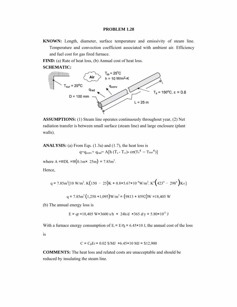
KNOWN: Length, diameter, surface temperature and emissivity of steam line.
Temperature and convection coefficient associated with ambient air. Efficiency
and fuel cost for gas fired furnace.
FIND: (a) Rate of heat loss, (b) Annual cost of heat loss.
SCHEMATIC:
ASSUMPTIONS: (1) Steam line operates continuously throughout year, (2) Net
radiation transfer is between small surface (steam line) and large enclosure (plant
walls).
ANALYSIS: (a) From Eqs. (1.3a) and (1.7), the heat loss is
q=qconv+ qrad= A[h (Ts - T∞)+ εσ(Ts Tsur )]
where A =πDL =π(0.1m× 25m) = 7.85m2.
Hence,
q = 7.85m2 10 W/m2.K(150 − 25)K + 0.8×5.67×10−8W/m2.K4(4234 − 2984 )K4
q = 7.85m2 (1,250 +1,095)W/m2 = (9813 + 8592)W =18,405 W
(b) The annual energy loss is
E = qt =18,405 W×3600 s/h × 24h/d ×365 d/y = 5.80×10¹¹ J
With a furnace energy consumption of Ef = E/ηf = 6.45×10 J, the annual cost of the loss
is
C = CgEf = 0.02 $/MJ ×6.45×10 MJ = $12,900 COMMENTS: The heat loss and related costs are unacceptable and should be
reduced by insulating the steam line.

PROBLEM 1.36
KNOWN: Inlet and outlet conditions for flow of water in a vertical tube.
FIND: (a) Change in combined thermal and flow work, (b) change in mechanical energy, and
(c)change in total energy of the water from the inlet to the outlet of the tube, (d) heat
transfer rate, q.
SCHEMATIC:
ASSUMPTIONS: (1) Steady-state conditions, (2) Uniform velocity distributions at the tube
inlet and outlet.
PROPERTIES: Table A.6 water (T = 110°C): ρ = 950 kg/m3, (T = (179.9°C + 110 °C)/2 =
145°C):cp = 4300 J/kg⋅K, ρ= 919 kg/m3. Other properties are taken from Moran, M.J. and
Shapiro, H.N., Fundamentals of Engineering Thermodynamics, 6th Edition, John Wiley &
Sons, Hoboken, 2008 including (psat = 10 bar): Tsat = 179.9°C, if = 762.81 kJ/kg; (p = 7 bar, T
= 600°C): i = 3700.2 kJ/kg, υ= 0.5738 m3/kg.
ANALYSIS: The steady-flow energy equation, in the absence of work (other than flow work),
is
(u+pv+1/2v2+gz)in- (u+pv+1/2v2+gz)out+q=0
(i+1/2v2+gz)in- (i+1/2v2+gz)out+q=0
while the conservation of mass principle yields
Vin= =. /
/ . =0.201m/s; Vout= =
. / . /
.
=110m/s

(a) The change in the combined thermal and flow work energy from inlet to outlet:
Ei,out –Ei,in = (i)out - (i)in = (i)out- [if ,sat +cp (Tin -Tsat )]
=1.5 kg/s 3700.2 kJ/kg- [762.81 kJ/kg +4.3 kJ/kg K (110 -179.9) ℃]
= 4.86 MW
where if,sat is the enthalpy of saturated liquid at the phase change temperature and pressure.
(b) The change in mechanical energy from inlet to outlet is:
Em,out-Em,in m(1/2v2+gz)out-m(i+1/2v2+gz)in
=1.5kg/s 1/2 (110m/s)2- 0.201m/s = 9.22KW
(c) The change in the total energy is the summation of the thermal, flow work, and
mechanical energy change or
Ein – Eout = 4.86 MW + 9.22 kW = 4.87 MW <
(d) The total heat transfer rate is the same as the total energy change, q = Ein – Eout = 4.87 MW
COMMENTS: (1) The change in mechanical energy, consisting of kinetic and potential
energy components, is negligible compared to the change in thermal and flow work
energy. (2) The average heat flux at the tube surface is q" = q /(π DL) = 4.87MW/(π ×
0.100 m×10 m) = 1.55 MW/m2 , which is very large. (3) The change in the velocity of the
water is inversely proportional to the change in the density. As such, the outlet velocity is
very large, and large pressure drops will occur in the vapor region of the tube relative to
the liquid region of the tube.
PROBLEM 1.62
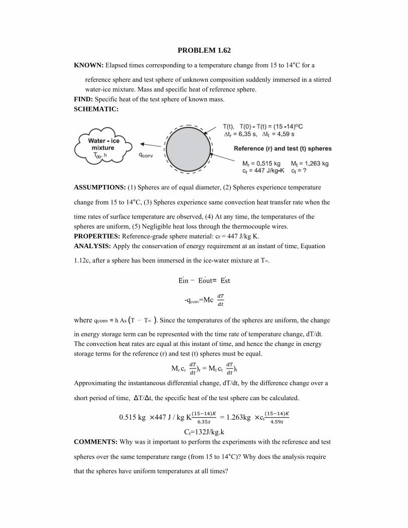
KNOWN: Elapsed times corresponding to a temperature change from 15 to 14°C for a
reference sphere and test sphere of unknown composition suddenly immersed in a stirred
water-ice mixture. Mass and specific heat of reference sphere.
FIND: Specific heat of the test sphere of known mass.
SCHEMATIC:
ASSUMPTIONS: (1) Spheres are of equal diameter, (2) Spheres experience temperature
change from 15 to 14°C, (3) Spheres experience same convection heat transfer rate when the
time rates of surface temperature are observed, (4) At any time, the temperatures of the
spheres are uniform, (5) Negligible heat loss through the thermocouple wires.
PROPERTIES: Reference-grade sphere material: cr = 447 J/kg K.
ANALYSIS: Apply the conservation of energy requirement at an instant of time, Equation
1.12c, after a sphere has been immersed in the ice-water mixture at T∞.
Eın − Eout= Est
-qconv=Mc
where qconv = h As (T − T∞ ). Since the temperatures of the spheres are uniform, the change
in energy storage term can be represented with the time rate of temperature change, dT/dt.
The convection heat rates are equal at this instant of time, and hence the change in energy
storage terms for the reference (r) and test (t) spheres must be equal.
Mr cr )r = Mt ct )t
Approximating the instantaneous differential change, dT/dt, by the difference change over a
short period of time, ΔT/Δt, the specific heat of the test sphere can be calculated.
0.515 kg 447 J / kg K.
= 1.263kg ct .
Ct=132J/kg.k COMMENTS: Why was it important to perform the experiments with the reference and test
spheres over the same temperature range (from 15 to 14°C)? Why does the analysis require
that the spheres have uniform temperatures at all times?

PROBLEM 2.6
KNOWN: Rod consisting of two materials with same lengths. Ratio of thermal conductivities.
FIND: Sketch temperature and heat flux distributions.
SCHEMATIC:
ASSUMPTIONS: (1) Steady-state conditions, (2) One-dimensional conduction, (3) Constant
properties, (3) No internal generation.
ANALYSIS: From Equation 2.19 for steady-state, one-dimensional conduction with constant
properties and no internal heat generation,
∂0
′′0
From these equations we know that heat flux is constant and the temperature gradient is inversely
proportional to k. Thus, with kA = 0.5kB, we can sketch the temperature and heat flux distributions
as shown below:
COMMENTS: (1) Note the discontinuity in the slope of the temperature distribution at x/L = 0.5.
The constant heat flux is in the negative x-direction. (2) A discontinuity in the temperature
distribution may occur at x/L = 0.5 due the joining of dissimilar materials. We shall address
thermal contact resistances in Chapter 3.

PROBLEM 2.12
KNOWN: Plane wall with prescribed thermal conductivity, thickness, and surface temperatures.
FIND: Heat flux, qx’’ , and temperature gradient, dT/dx, for the three different coordinate systems
shown.
SCHEMATIC:
ASSUMPTIONS: (1) One-dimensional heat flow, (2) Steady-state conditions, (3) No internal
generation, (4) Constant properties.
ANALYSIS: The rate equation for conduction heat transfer is
qx’’ = -k (1)
where the temperature gradient is constant throughout the wall and of the form
(2)
Substituting numerical values, find the temperature gradients,
(a) .
2000 / ・ ・
(b).
= 2000 /
(c).
2000 /
The heat rates, using Eq. (1) with k = 100 W/m.K, are
(a) q’’= -100 W /m.k×2000 K/m=-200 kW/m・ ・ ・ ・
(b) q’’= -100 W /m.k×(-2000 K/m)= 200 kW/m ・ ・ ・ ・
(c) q’’= -100 W /m.k×2000 K/m=-200 kW/m・・・ ・ ・

PROBLEM 2.26
KNOWN: Temperature distribution, T(x,y,z), within an infinite, homogeneous body at a given
instant of time.
FIND: Regions where the temperature changes with time.
SCHEMATIC:
ASSUMPTIONS: (1) Constant properties of infinite medium and (2) No internal heat generation.
ANALYSIS: The temperature distribution throughout the medium, at any instant of time, must
satisfy the heat equation. For the three-dimensional cartesian coordinate system, with constant
properties and no internal heat generation, the heat equation, Eq. 2.21, has the form
・ (1)
If T(x,y,z) satisfies this relation, conservation of energy is satisfied at every point in the medium.
Substituting T(x,y,z) into the Eq. (1), first find the gradients,
・ 2 4 2 2 21
Performing the differentiations,
2 – 4+ 2 =1
Hence,
0
which implies that, at the prescribed instant, the temperature is everywhere independent of time.
COMMENTS: Since we do not know the initial and boundary conditions, we cannot determine
the temperature distribution, T(x,y,z), at any future time. We can only determine that, for this
special instant of time, the temperature will not change.
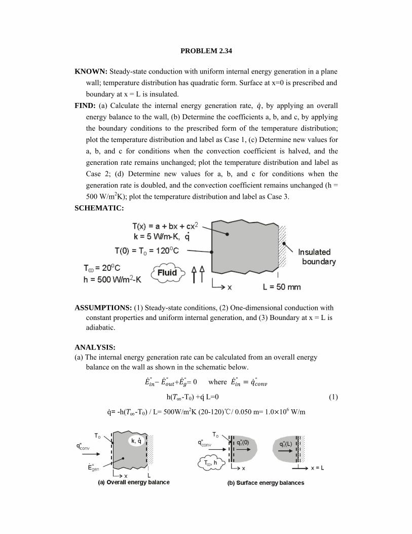
PROBLEM 2.34
KNOWN: Steady-state conduction with uniform internal energy generation in a plane
wall; temperature distribution has quadratic form. Surface at x=0 is prescribed and
boundary at x = L is insulated.
FIND: (a) Calculate the internal energy generation rate, , by applying an overall
energy balance to the wall, (b) Determine the coefficients a, b, and c, by applying
the boundary conditions to the prescribed form of the temperature distribution;
plot the temperature distribution and label as Case 1, (c) Determine new values for
a, b, and c for conditions when the convection coefficient is halved, and the
generation rate remains unchanged; plot the temperature distribution and label as
Case 2; (d) Determine new values for a, b, and c for conditions when the
generation rate is doubled, and the convection coefficient remains unchanged (h =
500 W/m2K); plot the temperature distribution and label as Case 3.
SCHEMATIC:
ASSUMPTIONS: (1) Steady-state conditions, (2) One-dimensional conduction with constant properties and uniform internal generation, and (3) Boundary at x = L is adiabatic.
ANALYSIS: (a) The internal energy generation rate can be calculated from an overall energy
balance on the wall as shown in the schematic below.
" " "0 where " "
h( -T0) +qL=0 (1)
q= -h( -T0) / L= 500W/m2K (20-120)℃/ 0.050 m= 1.0 106 W/m
(b) The coefficients of the temperature distribution, T(x) = a + bx + cx2, can be evaluated by applying the boundary conditions at x = 0 and x = L. See Table 2.2 for representation of the boundary conditions, and the schematic above for the relevant surface energy balances.
Boundary condition at x = 0, convection surface condition
E’’in-E
’’out=q’’
conv-q’’x(0)=0 where q’’
x(0)=-k |x=0
h( -T0) – [-k(0+b+2cx)x=0]=0 b=- h( -T0) / k=-500 [w/m2.K] (20-120) ℃/5w/m.k =1.0 10 K/m
Boundary condition at x = L, adiabatic or insulated surface
Eın-Eout = -q’’x(L) =0 where q’’x(L)= -k |x=L
K[0+b+2cx]x=L=0 C=-b/2L=-1.0 10 K/m/(2 0.050 1.0 105K/m2
Since the surface temperature at x = 0 is known, T(0) = To = 120℃, find
T(0)=120℃=a+b*0+c*0 or a=120℃ (4) Using the foregoing coefficients with the expression for T(x) in the Workspace of IHT, the temperature distribution can be determined and is plotted as Case 1 in the graph below.
(c) Consider Case 2 when the convection coefficient is halved, h2 = h/2 = 250 W/m2.k,
q=1 106W/m3 and other parameters remain unchanged except that T0 120℃.
We can determine a, b, and c for the temperature distribution expression by repeating
the analyses of parts (a) and (b).
Overall energy balance on the wall, see Eqs. (1,4)
a T0 qL/ h +T =1 106W/m 0.050m/ 250W/m K + 20℃= 220℃
Surface energy balance at x = 0, see Eq. (2)
b =- h(T-T0)/k = -250W/mK (20-220) ℃/5W/m. K = 1.0 10 K/m
Surface energy balance at x = L, see Eq. (3)
c =-b/2L =-1.0 10 k/m/(2 .050m 1.0 105 K/m2
The new temperature distribution, T2 (x), is plotted as Case 2 below.
(d) Consider Case 3 when the internal energy volumetric generation rate is doubled,
=2q= 2 106w/m, h = 500 W/m2.k, and other parameters remain unchanged
except that T0 220℃. Following the same analysis as part (c), the coefficients for
the new temperature distribution, T (x), are
a =220℃ b=2 10 k/mc=-2 105 K/m2

and the distribution is plotted as Case 3 below.
COMMENTS: Note the following features in the family of temperature distributions plotted above. The temperature gradients at x = L are zero since the boundary is insulated (adiabatic) for all cases. The shapes of the distributions are all quadratic, with the maximum temperatures at the insulated boundary. By halving the convection coefficient for Case 2, we expect the surface temperature T0 to increase relative to the Case 1 value, since the same heat flux is removed from the wall ( L) but the convection resistance has increased. By doubling the generation rate for Case 3, we expect the surface temperature To to increase relative to the Case 1 value, since double the amount of heat flux is removed from the wall (2 L). Can you explain why T0 is the same for Cases 2 and 3, yet the insulated boundary temperatures are quite different? Can you explain the relative magnitudes of T(L) for the three cases?

PROBLEM 2.37
KNOWN: Temperature distribution in a semi-transparent medium subjected to radiative flux.
FIND: (a) Expressions for the heat flux at the front and rear surfaces, (b) Heat generation rate
q(x) , (c) Expression for absorbed radiation per unit surface area in terms of A, a, B, C,
L, and k.
SCHEMATIC:
ASSUMPTIONS: (1) Steady-state conditions, (2) One-dimensional conduction in medium,
(3)Constant properties, (4) All laser irradiation is absorbed and can be characterized by an
internal volumetric heat generation term q(x).
ANALYSIS: (a) Knowing the temperature distribution, the surface heat fluxes are found
using Fourier’s law,
q
Front Surface, x=0
q Rear Surface, x=L:
q
(b) The heat diffusion equation for the medium is
ddx
dTdx
0 ddx
dTdx
qx
(c) Performing an energy balance on the medium,
Ein EoutEg 0
recognize that Egrepresents the absorbed irradiation. On a unit area basis
E’’g=E’’
in+E’’out=-q’’
x(0)+q’’x(L)= 1
Alternatively, evaluate Eg’’by integration over the volume of the medium,
E’’g= 1

PROBLEM 2.51
KNOWN: Temperature distribution in a spherical shell.
FIND: Whether conditions are steady-state or transient. Manner in which heat flux and heat rate
vary with radius.
SCHEMATIC:
ASSUMPTIONS: (1) One-dimensional conduction in r, (2) Constant properties.
ANALYSIS: From Equation 2.29, the heat equation reduces to
1
1
Substituting for T(r),
1 1
10
Hence, steady-state conditions exist. From Equation 2.28, the radial component of the heat flux is
qr=-k
Hence, q’’r decreases with increasing q′′r∝ 1/ 2
At any radial location, the heat rate is
qr=4π 2q′′r =4πkc
Hence, qr is independent of r.
COMMENTS: The fact that qr is independent of r is consistent with the energy conservation
requirement. If qr is constant, the flux must vary inversely with the area perpendicular to the
direction of heat flow. Hence, qr’’ varies inversely with r2.