TransPod Ultra-High-Speed Tube Transportation: Dynamics...
10
ScienceDirect Available online at www.sciencedirect.com Procedia Engineering 199 (2017) 8–17 1877-7058 © 2017 The Authors. Published by Elsevier Ltd. Peer-review under responsibility of the organizing committee of EURODYN 2017. 10.1016/j.proeng.2017.09.142 © 2017 The Authors. Published by Elsevier Ltd. Peer-review under responsibility of the organizing committee of EURODYN 2017. Keywords: Tube transportation, Vactrain, Evacuated Tube Transportation, Hyperloop, TransPod, Multi-modal dynamics, PFA analysis, AF transform, High dynamic range sensing, HDR sensing, Veillance flux, Real-time AI, Real-time machine learning, Vortex AI 1. Introduction Tube-based vacuum transportation was conceptualized over 100 years ago, as a means to achieve ultra-high-speed ground transportation and efficient inter-city travel. An early version was prototyped in 1909 by Boris Weinberg, a Russian professor who built a model of his proposed system at Tomsk Polytechnic University, and published the concept in 1914 in a book, “Motion without friction (airless electric way)” [1][2]. Robert Goddard, a pioneer of rocket design and one of the forefathers of space exploration, proposed a similar concept, published in 1909 and 1914 [3]. Goddard’s system, patented after his death, included vacuum pumps to reduce air pressure in a tunnel guideway, and a vehicle design which was levitated by magnets [4]. Nearly 50 years previously, pneumatic railways were an early predecessor to this concept — with trains affixed with a baffle moving along inside tubes, while fans created a pressure differential in the tubes to deliver force. Functioning versions of this system were installed in London and New York in the 1860s-70s. The Crystal Palace Pneumatic * Acknowledgments to TransPod staff and others listed below. E-mail address: [email protected] Tel.: +1.416.673.6607 X International Conference on Structural Dynamics, EURODYN 2017 TransPod Ultra-High-Speed Tube Transportation: Dynamics of Vehicles and Infrastructure Ryan Janzen a,b,* a TransPod Inc., 101 College St., Toronto, Ontario M5G1L7, Canada b University of Toronto, Department of Electrical and Computer Engineering, 10 King’s College Road, Mailroom SFB540, Toronto, Ontario M5S3G4, Canada Abstract A next-generation mass transportation system, consisting of TransPod aerospace vehicles designed to carry passengers at speeds exceeding 1000 km/h, is presented with respect to dynamics considerations. This system is based on electromagnetic propulsion of vehicles within a protected tube guideway, whose air pressure is reduced and controlled for improved performance at high speed. The tube environment is designed for levitation systems, stability systems, and safety support systems, to permit multiple TransPod vehicles to run simultaneously with high-frequency departures. The design of this vehicle and tube structure is aided by analysis of structural dynamics and aerodynamics, presented in this paper with selected novel topics in physical-fourier-amplitude-domain analysis, and machine-learning-based vibration sensing and control. c 2017 The Authors. Published by Elsevier Ltd.
-
Upload
vuonghuong -
Category
Documents
-
view
223 -
download
4
Transcript of TransPod Ultra-High-Speed Tube Transportation: Dynamics...

ScienceDirect
Available online at www.sciencedirect.com
Procedia Engineering 199 (2017) 8–17
1877-7058 © 2017 The Authors. Published by Elsevier Ltd.Peer-review under responsibility of the organizing committee of EURODYN 2017.10.1016/j.proeng.2017.09.142
10.1016/j.proeng.2017.09.142
© 2017 The Authors. Published by Elsevier Ltd.Peer-review under responsibility of the organizing committee of EURODYN 2017.
1877-7058
Available online at www.sciencedirect.com
Procedia Engineering 00 (2017) 000–000www.elsevier.com/locate/procedia
X International Conference on Structural Dynamics, EURODYN 2017
TransPod Ultra-High-Speed Tube Transportation:Dynamics of Vehicles and Infrastructure
Ryan Janzena,b,∗
aTransPod Inc., 101 College St., Toronto, Ontario M5G1L7, CanadabUniversity of Toronto, Department of Electrical and Computer Engineering,
10 King’s College Road, Mailroom SFB540, Toronto, Ontario M5S3G4, Canada
Abstract
A next-generation mass transportation system, consisting of TransPod aerospace vehicles designed to carry passengers at speedsexceeding 1000 km/h, is presented with respect to dynamics considerations. This system is based on electromagnetic propulsion ofvehicles within a protected tube guideway, whose air pressure is reduced and controlled for improved performance at high speed.The tube environment is designed for levitation systems, stability systems, and safety support systems, to permit multiple TransPodvehicles to run simultaneously with high-frequency departures. The design of this vehicle and tube structure is aided by analysisof structural dynamics and aerodynamics, presented in this paper with selected novel topics in physical-fourier-amplitude-domainanalysis, and machine-learning-based vibration sensing and control.c© 2017 The Authors. Published by Elsevier Ltd.Peer-review under responsibility of the organizing committee of EURODYN 2017.
Keywords: Tube transportation, Vactrain, Evacuated Tube Transportation, Hyperloop, TransPod, Multi-modal dynamics, PFA analysis, AFtransform, High dynamic range sensing, HDR sensing, Veillance flux, Real-time AI, Real-time machine learning, Vortex AI
1. Introduction
Tube-based vacuum transportation was conceptualized over 100 years ago, as a means to achieve ultra-high-speedground transportation and efficient inter-city travel. An early version was prototyped in 1909 by Boris Weinberg,a Russian professor who built a model of his proposed system at Tomsk Polytechnic University, and published theconcept in 1914 in a book, “Motion without friction (airless electric way)” [1][2].
Robert Goddard, a pioneer of rocket design and one of the forefathers of space exploration, proposed a similarconcept, published in 1909 and 1914 [3]. Goddard’s system, patented after his death, included vacuum pumps toreduce air pressure in a tunnel guideway, and a vehicle design which was levitated by magnets [4].
Nearly 50 years previously, pneumatic railways were an early predecessor to this concept — with trains affixed witha baffle moving along inside tubes, while fans created a pressure differential in the tubes to deliver force. Functioningversions of this system were installed in London and New York in the 1860s-70s. The Crystal Palace Pneumatic
∗ Acknowledgments to TransPod staff and others listed below.E-mail address: [email protected] Tel.: +1.416.673.6607
1877-7058 c© 2017 The Authors. Published by Elsevier Ltd.Peer-review under responsibility of the organizing committee of EURODYN 2017.
2 RJ / Procedia Engineering 00 (2017) 000–000
Railway and the Beach Pneumatic Subway, respectively, carried passengers a short distance inside each city [5,6], butthese systems pre-dated the large-scale development of vacuum technology, and could not take advantage of reducedfriction for high-speed inter-city travel.
The vacuum train (vactrain) concept continued development in recent decades, with improvements in industrialvacuum pump technology. Robert Salter proposed a further system which was electromagnetically-driven and regen-erated electricity during braking. The “very high speed transit” (VHST) was proposed to share tunnels with oil, waterand gas pipelines [7]. Other proposals included “Evacuated tube transport” (ETT) in the 1990s [8], “SwissMetro” inthe 1990s-2000s [9][10][11], and “Hyperloop” in 2013 [12][13]. Further developments have been ongoing to makethe design practical with added reliability and cost performance.
TransPod proposed a novel system to address these issues, combining elements of spacecraft design, aircraft design,and rail network design [14]. In TransPod’s system, pressurized passenger and cargo vehicles travel in a low-pressuretube environment, driven by electromagnetic propulsion, designed to operate at speeds exceeding 1000 km/h.
TransPod’s system is composed of vehicles which pair with a specially-designed tube guideway surface, as well aspressure management, structural and support infrastructure. The system is designed with the following objectives:
• High-speed passenger transportation – greatly exceeding the speed capability of high-speed rail and conven-tional trains, and exceeding the speed of fossil-fuel-dependent airline jet flights.• High-frequency departures: passengers need not plan a trip long in advance, as is typical for airline flights.• Reduced fossil fuel dependency and greenhouse gas emissions – TransPod’s fully-electric system is designed to
be linked to the electrical grid, via substations positioned external to the tube infrastructure. Rather than usingfossil fuels on-board, the vehicles pick up the tube infrastructure’s electrical power inside the tube.• Elimination of fuel waste of an airline jet ascending to altitude (a significant proportion of fuel consumption for
short-haul flights). TransPod ground-based vehicles avoid this inefficiency and operating cost factor.• Mass transportation to reduce highway congestion between major cities, reducing economic losses due to traffic
delays and the time taken to drive at only 100 km/h or less. Reducing maintenance on major highways.
Development of this system is a large-scale engineering project, currently underway: developing all elements ofthe vehicles and infrastructure, including propulsion systems, levitation systems, electrical, thermal, pressure man-agement, vehicle structure, and intelligent guidance and control systems — incorporating novel research.
1.1. Overview of this paper
In this work we will examine selected dynamics of the tube structure and vehicle interaction, related to the follow-ing systems and phenomena:
• Propulsion and levitation systems;• Aerodynamic effects of vehicle travel inside the tube;• Tube response to a moving load (moving vehicle inside the tube);• Tube natural oscillation and dynamics;• Tube dynamic forces caused by wind aerodynamics outside the tube.
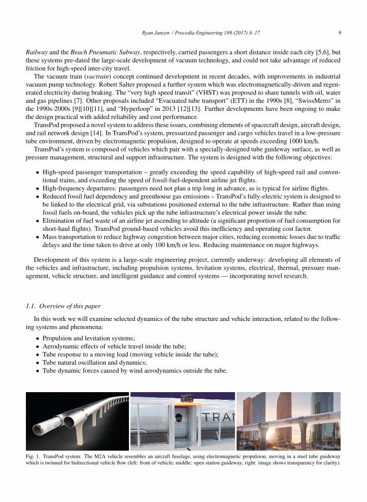
Fig. 1. TransPod system: The M2A vehicle resembles an aircraft fuselage, using electromagnetic propulsion, moving in a steel tube guidewaywhich is twinned for bidirectional vehicle flow (left: front of vehicle; middle: open station guideway; right: image shows transparency for clarity).
Ryan Janzen / Procedia Engineering 199 (2017) 8–17 9Available online at www.sciencedirect.com
Procedia Engineering 00 (2017) 000–000www.elsevier.com/locate/procedia
X International Conference on Structural Dynamics, EURODYN 2017
TransPod Ultra-High-Speed Tube Transportation:Dynamics of Vehicles and Infrastructure
Ryan Janzena,b,∗
aTransPod Inc., 101 College St., Toronto, Ontario M5G1L7, CanadabUniversity of Toronto, Department of Electrical and Computer Engineering,
10 King’s College Road, Mailroom SFB540, Toronto, Ontario M5S3G4, Canada
Abstract
A next-generation mass transportation system, consisting of TransPod aerospace vehicles designed to carry passengers at speedsexceeding 1000 km/h, is presented with respect to dynamics considerations. This system is based on electromagnetic propulsion ofvehicles within a protected tube guideway, whose air pressure is reduced and controlled for improved performance at high speed.The tube environment is designed for levitation systems, stability systems, and safety support systems, to permit multiple TransPodvehicles to run simultaneously with high-frequency departures. The design of this vehicle and tube structure is aided by analysisof structural dynamics and aerodynamics, presented in this paper with selected novel topics in physical-fourier-amplitude-domainanalysis, and machine-learning-based vibration sensing and control.c© 2017 The Authors. Published by Elsevier Ltd.Peer-review under responsibility of the organizing committee of EURODYN 2017.
Keywords: Tube transportation, Vactrain, Evacuated Tube Transportation, Hyperloop, TransPod, Multi-modal dynamics, PFA analysis, AFtransform, High dynamic range sensing, HDR sensing, Veillance flux, Real-time AI, Real-time machine learning, Vortex AI
1. Introduction
Tube-based vacuum transportation was conceptualized over 100 years ago, as a means to achieve ultra-high-speedground transportation and efficient inter-city travel. An early version was prototyped in 1909 by Boris Weinberg,a Russian professor who built a model of his proposed system at Tomsk Polytechnic University, and published theconcept in 1914 in a book, “Motion without friction (airless electric way)” [1][2].
Robert Goddard, a pioneer of rocket design and one of the forefathers of space exploration, proposed a similarconcept, published in 1909 and 1914 [3]. Goddard’s system, patented after his death, included vacuum pumps toreduce air pressure in a tunnel guideway, and a vehicle design which was levitated by magnets [4].
Nearly 50 years previously, pneumatic railways were an early predecessor to this concept — with trains affixed witha baffle moving along inside tubes, while fans created a pressure differential in the tubes to deliver force. Functioningversions of this system were installed in London and New York in the 1860s-70s. The Crystal Palace Pneumatic
∗ Acknowledgments to TransPod staff and others listed below.E-mail address: [email protected] Tel.: +1.416.673.6607
1877-7058 c© 2017 The Authors. Published by Elsevier Ltd.Peer-review under responsibility of the organizing committee of EURODYN 2017.
Available online at www.sciencedirect.com
Procedia Engineering 00 (2017) 000–000www.elsevier.com/locate/procedia
X International Conference on Structural Dynamics, EURODYN 2017
TransPod Ultra-High-Speed Tube Transportation:Dynamics of Vehicles and Infrastructure
Ryan Janzena,b,∗
aTransPod Inc., 101 College St., Toronto, Ontario M5G1L7, CanadabUniversity of Toronto, Department of Electrical and Computer Engineering,
10 King’s College Road, Mailroom SFB540, Toronto, Ontario M5S3G4, Canada
Abstract
A next-generation mass transportation system, consisting of TransPod aerospace vehicles designed to carry passengers at speedsexceeding 1000 km/h, is presented with respect to dynamics considerations. This system is based on electromagnetic propulsion ofvehicles within a protected tube guideway, whose air pressure is reduced and controlled for improved performance at high speed.The tube environment is designed for levitation systems, stability systems, and safety support systems, to permit multiple TransPodvehicles to run simultaneously with high-frequency departures. The design of this vehicle and tube structure is aided by analysisof structural dynamics and aerodynamics, presented in this paper with selected novel topics in physical-fourier-amplitude-domainanalysis, and machine-learning-based vibration sensing and control.c© 2017 The Authors. Published by Elsevier Ltd.Peer-review under responsibility of the organizing committee of EURODYN 2017.
Keywords: Tube transportation, Vactrain, Evacuated Tube Transportation, Hyperloop, TransPod, Multi-modal dynamics, PFA analysis, AFtransform, High dynamic range sensing, HDR sensing, Veillance flux, Real-time AI, Real-time machine learning, Vortex AI
1. Introduction
Tube-based vacuum transportation was conceptualized over 100 years ago, as a means to achieve ultra-high-speedground transportation and efficient inter-city travel. An early version was prototyped in 1909 by Boris Weinberg,a Russian professor who built a model of his proposed system at Tomsk Polytechnic University, and published theconcept in 1914 in a book, “Motion without friction (airless electric way)” [1][2].
Robert Goddard, a pioneer of rocket design and one of the forefathers of space exploration, proposed a similarconcept, published in 1909 and 1914 [3]. Goddard’s system, patented after his death, included vacuum pumps toreduce air pressure in a tunnel guideway, and a vehicle design which was levitated by magnets [4].
Nearly 50 years previously, pneumatic railways were an early predecessor to this concept — with trains affixed witha baffle moving along inside tubes, while fans created a pressure differential in the tubes to deliver force. Functioningversions of this system were installed in London and New York in the 1860s-70s. The Crystal Palace Pneumatic
∗ Acknowledgments to TransPod staff and others listed below.E-mail address: [email protected] Tel.: +1.416.673.6607
1877-7058 c© 2017 The Authors. Published by Elsevier Ltd.Peer-review under responsibility of the organizing committee of EURODYN 2017.
2 RJ / Procedia Engineering 00 (2017) 000–000
Railway and the Beach Pneumatic Subway, respectively, carried passengers a short distance inside each city [5,6], butthese systems pre-dated the large-scale development of vacuum technology, and could not take advantage of reducedfriction for high-speed inter-city travel.
The vacuum train (vactrain) concept continued development in recent decades, with improvements in industrialvacuum pump technology. Robert Salter proposed a further system which was electromagnetically-driven and regen-erated electricity during braking. The “very high speed transit” (VHST) was proposed to share tunnels with oil, waterand gas pipelines [7]. Other proposals included “Evacuated tube transport” (ETT) in the 1990s [8], “SwissMetro” inthe 1990s-2000s [9][10][11], and “Hyperloop” in 2013 [12][13]. Further developments have been ongoing to makethe design practical with added reliability and cost performance.
TransPod proposed a novel system to address these issues, combining elements of spacecraft design, aircraft design,and rail network design [14]. In TransPod’s system, pressurized passenger and cargo vehicles travel in a low-pressuretube environment, driven by electromagnetic propulsion, designed to operate at speeds exceeding 1000 km/h.
TransPod’s system is composed of vehicles which pair with a specially-designed tube guideway surface, as well aspressure management, structural and support infrastructure. The system is designed with the following objectives:
• High-speed passenger transportation – greatly exceeding the speed capability of high-speed rail and conven-tional trains, and exceeding the speed of fossil-fuel-dependent airline jet flights.• High-frequency departures: passengers need not plan a trip long in advance, as is typical for airline flights.• Reduced fossil fuel dependency and greenhouse gas emissions – TransPod’s fully-electric system is designed to
be linked to the electrical grid, via substations positioned external to the tube infrastructure. Rather than usingfossil fuels on-board, the vehicles pick up the tube infrastructure’s electrical power inside the tube.• Elimination of fuel waste of an airline jet ascending to altitude (a significant proportion of fuel consumption for
short-haul flights). TransPod ground-based vehicles avoid this inefficiency and operating cost factor.• Mass transportation to reduce highway congestion between major cities, reducing economic losses due to traffic
delays and the time taken to drive at only 100 km/h or less. Reducing maintenance on major highways.
Development of this system is a large-scale engineering project, currently underway: developing all elements ofthe vehicles and infrastructure, including propulsion systems, levitation systems, electrical, thermal, pressure man-agement, vehicle structure, and intelligent guidance and control systems — incorporating novel research.
1.1. Overview of this paper
In this work we will examine selected dynamics of the tube structure and vehicle interaction, related to the follow-ing systems and phenomena:
• Propulsion and levitation systems;• Aerodynamic effects of vehicle travel inside the tube;• Tube response to a moving load (moving vehicle inside the tube);• Tube natural oscillation and dynamics;• Tube dynamic forces caused by wind aerodynamics outside the tube.
Fig. 1. TransPod system: The M2A vehicle resembles an aircraft fuselage, using electromagnetic propulsion, moving in a steel tube guidewaywhich is twinned for bidirectional vehicle flow (left: front of vehicle; middle: open station guideway; right: image shows transparency for clarity).

10 Ryan Janzen / Procedia Engineering 199 (2017) 8–17RJ / Procedia Engineering 00 (2017) 000–000 3
Additionally, two novel methods are summarized: (1) PFA analysis to visualize and merge amplitude-frequency-domain structural dynamics data; and (2) a machine-learning system to perform real-time monitoring of this data.
1.2. Basic principles of operation
1.2.1. LevitationIt is advantageous to levitate the vehicle off the bottom of the tube’s traction infrastructure. By maintaining a gap
between the vehicle and infrastructure at high speeds, vehicle vibration can be reduced with the following advantages:
• Increased comfort to passengers;• Reduced maintenance requirements on vibration-sensitive components in the vehicle;• Increased reliability with reduced breakdowns due to vibration loads on vehicle systems;• Reduced requirements on smoothness of the traction surface.
Air bearings were proposed as a levitation system, in one of the previous vactrain concepts (“hyperloop”) [12].However, a major drawback of air bearings is an extremely high positional dependence, i.e. a very large inverse ratiobetween gap separation distance and levitation force. As a result, tiny irregularities (< 0.01mm) in the traction surfacecan cause drastic changes to levitation force. The momentary losses in levitation can cause a bearing to slam down onthe traction surface and risk self-damage. TransPod’s system provides consistent forces (± 21%) for a much greater1mm tolerance in the traction surface, and even greater force variations can be corrected by the active control system.
TransPod’s M2A vehicle uses magnetodynamic levitation based on repulsion forces from time-varying magneticfields. These repulsive forces are based on fundamentals of electromagnetics, represented by two of Maxwell’s equa-tions: ∮
∂S
�E · d�l = − ddt
∫∫S
�B · d�S (1)
∮∂S
�B · d�l = µ∫∫
S
�J · d�S (2)
with �E and �B representing electric and magnetic fields, respectively, µ as a material-dependent magnetic permeability,and �J as current density, as measured over an arbitrary surface S with loop contour ∂S over increments d�l (neglectingdisplacement current in the final equation). These equations are fundamental to the electromagnetic properties atevery point in the universe, even governing light propagation since it itself is an electromagnetic wave.
In the TransPod system, the second equation is important in expressing the fact that a magnetic field is created byan electric current, circulating around the current’s line of propagation. The first equation states that a time-variationin that magnetic field creates a circulating electric field (including in nearby materials such as a circular conductiveloop). In turn, the time-varying electric field generates its own circulating current, which in turn creates a magneticfield which opposes the original rate of change of the original magnetic field. As a result, it is possible to createrepulsive forces between the vehicle and tube levitation systems. These systems are designed with multiple magneticelements in a specific geometry, along with control systems, to stabilize the vehicle position.
1.2.2. PropulsionThe levitated vehicle employs non-contact propulsion engines. A traction force is generated through the use of
moving electromagnetic fields, which are created by linear multi-pole motors. The basic principle of operation of alinear engine, such as a linear induction motor (LIM), is as follows. A series of magnetically-conductive poles arearranged in a linear sequence with the direction of vehicle motion. Time-varying electric currents are driven throughwindings on the poles, to create time-varying magnetic fields which interact between the tube and vehicle.
Linear induction motors are a well-studied technology [15–20] with a long history of industrial use. These devicesare formed by arrays of windings on laminated material, to conduct magnetic flux. Using three-phase pulse-width-modulated (PWM) sinusoidal waveforms, the linear arrangement replicates the action of a spatially-moving magneticfield. This generates longitudinal propulsion force which is carried through the structure of the vehicle.
4 RJ / Procedia Engineering 00 (2017) 000–000
Vehicle3
Vehicle2
TubeInfrastructure
Propulsion
Levitation
Stability Sys.
Wind Load
Wind Vortex Shedding
Precipitation
Geological Vibration
Ground Shift and Settling
Sunlight and Temperature
Vehicle1
Aerodynamicsand Pressure State
Aerodynamics
Lateral load on tube structure:10-6~10-3 HzNote: There is additional spectral contentextending below 10-7 Hz, for regions withseasonal average wind directions, wherethe wind load on average is biased towarda specific direction.
Expansion, contraction, deformationof the tube structure:10-5 Hz representing the daily cycle, and3x10-8 Hz representing the annual cycle,plus harmonics.
Rain load; static snow and ice load:10-6~10-2 Hz - loading and mass distrib.effects on osc. modes from other forces.
10-3 ~103 Hz AC signal
10-3 ~103 Hz AC signal
10-1 ~102 Hz vibration
Terrain and Foundation Shift:< 10-7 Hz - Effect on section alignment,and potential feedback loops leading topotential further shift from reaction forcefrom vehicle stability system.
Fluid Dynamics: 10-1 ~103 Hz turbulent spectra 10-3 ~10-2 Hz
trip pressure profile
Vibrating load on tube structure:10-1~101 Hz related to Strouhal number.
Seismic Waves:10-2~102 Hz - Primary (long.), Sec. (lat.),Surface waves: (Rayleigh, Love, Stoneley)
Fig. 2. Schematic diagram: Interaction of dynamic forces on the TransPod system, with order-of-magnitude frequency ranges for comparison..
2. Dynamic forces and their interplay
Compared to aircraft, tube-based vehicles are protected from atmospheric phenomena such as turbulence, mi-crobursts, storms, lightning strikes, and collisions with flocks of birds, to the degree that the tube is sealed. In aground-based vehicle, electrically-driven propulsion in a controlled guideway with reduced air resistance presentsseveral advantages, as outlined earlier. Meanwhile, several interesting dynamics effects come into play, and these willbe described with reference to TransPod’s vehicle design.
The moving vehicle experiences aerodynamic and magnetodynamic forces, internal structural dynamic forces, andinternal forces created by the payload (passengers and shifting cargo) as well as vehicle subsystems with movingcomponents including pumps and turbomachinery. These forces are sensed and corrected by an inertial guidancesystem. Deviations of the vehicle’s trajectory are sensed and tracked by a combination of inertial sensors and opticalsensors (optical proximity and computer-vision systems) which provide high-speed data and contact-free operation.
As the vehicle passes each point on the infrastructure, its load forces are transferred to the tube, including gravi-tational forces, propulsion forces, centripetal forces during turns, and forces transferred from the stability system inorder to overcome various vibrations and perturbations on the vehicle. Therefore, the tube structure’s own dynamicsplay a key role. Additional forces on the tube structure include wind forces and geological forces.
The interactions between these forces are illustrated in Fig. 2, with order-of-magnitude frequency ranges for com-parison. This paper presents a basic introduction to three elements: aerodynamics of the vehicle inside the TransPodtube structure, self-oscillation dynamics of the tube structure, and oscillation from wind loading on the tube structure.
3. Aerodynamics: Vehicle inside tube
In a reduced-air-pressure environment for high speed motion, there still exist limits on vehicle speed. For anyvehicle moving through air in a confined channel, tube or guideway, this limit is known as the Kantrowitz limit.It applies to trains, automobiles, as well as the TransPod system. More technically, the Kantrowitz limit describeschoked flow, where a contraction in cross-sectional area causes an increase in flow velocity according to the continuityequation. At the limit when this velocity reaches the local speed of sound, the flow becomes choked, and no furtherincrease in flow rate can be achieved, despite changes in pressure upstream or downstream.

Ryan Janzen / Procedia Engineering 199 (2017) 8–17 11RJ / Procedia Engineering 00 (2017) 000–000 3
Additionally, two novel methods are summarized: (1) PFA analysis to visualize and merge amplitude-frequency-domain structural dynamics data; and (2) a machine-learning system to perform real-time monitoring of this data.
1.2. Basic principles of operation
1.2.1. LevitationIt is advantageous to levitate the vehicle off the bottom of the tube’s traction infrastructure. By maintaining a gap
between the vehicle and infrastructure at high speeds, vehicle vibration can be reduced with the following advantages:
• Increased comfort to passengers;• Reduced maintenance requirements on vibration-sensitive components in the vehicle;• Increased reliability with reduced breakdowns due to vibration loads on vehicle systems;• Reduced requirements on smoothness of the traction surface.
Air bearings were proposed as a levitation system, in one of the previous vactrain concepts (“hyperloop”) [12].However, a major drawback of air bearings is an extremely high positional dependence, i.e. a very large inverse ratiobetween gap separation distance and levitation force. As a result, tiny irregularities (< 0.01mm) in the traction surfacecan cause drastic changes to levitation force. The momentary losses in levitation can cause a bearing to slam down onthe traction surface and risk self-damage. TransPod’s system provides consistent forces (± 21%) for a much greater1mm tolerance in the traction surface, and even greater force variations can be corrected by the active control system.
TransPod’s M2A vehicle uses magnetodynamic levitation based on repulsion forces from time-varying magneticfields. These repulsive forces are based on fundamentals of electromagnetics, represented by two of Maxwell’s equa-tions: ∮
∂S
�E · d�l = − ddt
∫∫S
�B · d�S (1)
∮∂S
�B · d�l = µ∫∫
S
�J · d�S (2)
with �E and �B representing electric and magnetic fields, respectively, µ as a material-dependent magnetic permeability,and �J as current density, as measured over an arbitrary surface S with loop contour ∂S over increments d�l (neglectingdisplacement current in the final equation). These equations are fundamental to the electromagnetic properties atevery point in the universe, even governing light propagation since it itself is an electromagnetic wave.
In the TransPod system, the second equation is important in expressing the fact that a magnetic field is created byan electric current, circulating around the current’s line of propagation. The first equation states that a time-variationin that magnetic field creates a circulating electric field (including in nearby materials such as a circular conductiveloop). In turn, the time-varying electric field generates its own circulating current, which in turn creates a magneticfield which opposes the original rate of change of the original magnetic field. As a result, it is possible to createrepulsive forces between the vehicle and tube levitation systems. These systems are designed with multiple magneticelements in a specific geometry, along with control systems, to stabilize the vehicle position.
1.2.2. PropulsionThe levitated vehicle employs non-contact propulsion engines. A traction force is generated through the use of
moving electromagnetic fields, which are created by linear multi-pole motors. The basic principle of operation of alinear engine, such as a linear induction motor (LIM), is as follows. A series of magnetically-conductive poles arearranged in a linear sequence with the direction of vehicle motion. Time-varying electric currents are driven throughwindings on the poles, to create time-varying magnetic fields which interact between the tube and vehicle.
Linear induction motors are a well-studied technology [15–20] with a long history of industrial use. These devicesare formed by arrays of windings on laminated material, to conduct magnetic flux. Using three-phase pulse-width-modulated (PWM) sinusoidal waveforms, the linear arrangement replicates the action of a spatially-moving magneticfield. This generates longitudinal propulsion force which is carried through the structure of the vehicle.
4 RJ / Procedia Engineering 00 (2017) 000–000
Vehicle3
Vehicle2
TubeInfrastructure
Propulsion
Levitation
Stability Sys.
Wind Load
Wind Vortex Shedding
Precipitation
Geological Vibration
Ground Shift and Settling
Sunlight and Temperature
Vehicle1
Aerodynamicsand Pressure State
Aerodynamics
Lateral load on tube structure:10-6~10-3 HzNote: There is additional spectral contentextending below 10-7 Hz, for regions withseasonal average wind directions, wherethe wind load on average is biased towarda specific direction.
Expansion, contraction, deformationof the tube structure:10-5 Hz representing the daily cycle, and3x10-8 Hz representing the annual cycle,plus harmonics.
Rain load; static snow and ice load:10-6~10-2 Hz - loading and mass distrib.effects on osc. modes from other forces.
10-3 ~103 Hz AC signal
10-3 ~103 Hz AC signal
10-1 ~102 Hz vibration
Terrain and Foundation Shift:< 10-7 Hz - Effect on section alignment,and potential feedback loops leading topotential further shift from reaction forcefrom vehicle stability system.
Fluid Dynamics: 10-1 ~103 Hz turbulent spectra 10-3 ~10-2 Hz
trip pressure profile
Vibrating load on tube structure:10-1~101 Hz related to Strouhal number.
Seismic Waves:10-2~102 Hz - Primary (long.), Sec. (lat.),Surface waves: (Rayleigh, Love, Stoneley)
Fig. 2. Schematic diagram: Interaction of dynamic forces on the TransPod system, with order-of-magnitude frequency ranges for comparison..
2. Dynamic forces and their interplay
Compared to aircraft, tube-based vehicles are protected from atmospheric phenomena such as turbulence, mi-crobursts, storms, lightning strikes, and collisions with flocks of birds, to the degree that the tube is sealed. In aground-based vehicle, electrically-driven propulsion in a controlled guideway with reduced air resistance presentsseveral advantages, as outlined earlier. Meanwhile, several interesting dynamics effects come into play, and these willbe described with reference to TransPod’s vehicle design.
The moving vehicle experiences aerodynamic and magnetodynamic forces, internal structural dynamic forces, andinternal forces created by the payload (passengers and shifting cargo) as well as vehicle subsystems with movingcomponents including pumps and turbomachinery. These forces are sensed and corrected by an inertial guidancesystem. Deviations of the vehicle’s trajectory are sensed and tracked by a combination of inertial sensors and opticalsensors (optical proximity and computer-vision systems) which provide high-speed data and contact-free operation.
As the vehicle passes each point on the infrastructure, its load forces are transferred to the tube, including gravi-tational forces, propulsion forces, centripetal forces during turns, and forces transferred from the stability system inorder to overcome various vibrations and perturbations on the vehicle. Therefore, the tube structure’s own dynamicsplay a key role. Additional forces on the tube structure include wind forces and geological forces.
The interactions between these forces are illustrated in Fig. 2, with order-of-magnitude frequency ranges for com-parison. This paper presents a basic introduction to three elements: aerodynamics of the vehicle inside the TransPodtube structure, self-oscillation dynamics of the tube structure, and oscillation from wind loading on the tube structure.
3. Aerodynamics: Vehicle inside tube
In a reduced-air-pressure environment for high speed motion, there still exist limits on vehicle speed. For anyvehicle moving through air in a confined channel, tube or guideway, this limit is known as the Kantrowitz limit.It applies to trains, automobiles, as well as the TransPod system. More technically, the Kantrowitz limit describeschoked flow, where a contraction in cross-sectional area causes an increase in flow velocity according to the continuityequation. At the limit when this velocity reaches the local speed of sound, the flow becomes choked, and no furtherincrease in flow rate can be achieved, despite changes in pressure upstream or downstream.

12 Ryan Janzen / Procedia Engineering 199 (2017) 8–17RJ / Procedia Engineering 00 (2017) 000–000 5
Fig. 3. Aerodynamics along the TransPod M2A vehicle (simplified shape), in zero-aux-bypass conditions: density, pressure, velocity, temperature.
Aerodynamic shaping of the vehicle can indeed assist in the bypass of air, but the potential for choked flow inthe bypass cross-section presents a fundamental limit. In general, there are three broad categories of aerodynamicstrategies to overcome the Kantrowitz limit for a vehicle travelling in a confined tube:
• Tube diameter sufficiently large to allow sufficient air bypass around the vehicle;• Reduced air density (pressure) inside the tube environment;• Auxiliary bypass of tube air, through the vehicle from front to back.
A disadvantage of large-diameter tube segments is that the tube dimensions greatly affect the infrastructure cost.The remaining two options provide solutions which need not require material costs continuously at each point alongthe infrastructure cross-section. Rather, reducing the air pressure merely requires vacuum pump infrastructure at dis-crete points along the line; auxiliary bypass is only required on each vehicle, much less than the entire infrastructure.
Even while reducing air pressure in the tube, it is not practical to achieve a 100% vacuum, and therefore the vehiclestill experiences a degree of air resistance. With a nonzero average air density, it is possible to combine the abovethree strategies in a proportion that can be optimized based on energy efficiency, reliability, or cost. In particular, theauxiliary bypass strategy can include a gas forcing system, such as an axial compressor, on the vehicle to drive airthrough a preferred route with reduced cross-sectional area.
In this paper, we show an example of one particular TransPod vehicle having a compressor bypass. The TransPodM2A vehicle includes an electrically-driven axial compressor, with air diversion channels which extend from front-to-back of the vehicle, first directed downward after the compressor output, then under the passenger cabin floor,then upward, and finally through a nozzle at the back of the vehicle. This is a rocket-style exhaust nozzle, with anexpansion angle similar to rocket nozzles used in a space environment having a low ambient pressure. A small amountof forward thrust is generated by this system, but the main objective is to divert air from the front of the vehicle andthereby reduce air resistance from the confined motion inside the tube.
The TransPod M2A vehicle has an exterior profile which is represented in simplified form as in Fig. 3. Here, thedynamics are simulated in a zero-compressor-force failure mode.
In transportation system design, it is important to replicate all failure modes. For example, a lateral-stabilizationfailure scenario consists of a failure of the components which hold the vehicle aligned in the centre of the tube.In this case, the vehicle would stray off-centre during a turn in the tube route. However, additionally, we wishto examine the vehicle’s stability in a loss-of-stabilization scenario—whether the offset is self-correcting or self-amplifying. Therefore, a CFD aerodynamic analysis was performed for the following conditions: vehicle positionedoff-centre by 0.325m in the +Z direction, moving at velocity vx = 300m/s, under the conditions of 100 Pa ambient
6 RJ / Procedia Engineering 00 (2017) 000–000
0 0.05 0.1 0.15 0.20
1000
2000
X
Fo
rce
(N
)
Lo
ng
itu
din
al L
ine
ar
0 0.05 0.1 0.15 0.2-20
0
20
Y
Fo
rce
(N
)
Ve
rtic
al L
ine
ar
0 0.05 0.1 0.15 0.2
Time (s)
-500
0
500
Z
Fo
rce
(N
)
La
tera
l L
ine
ar
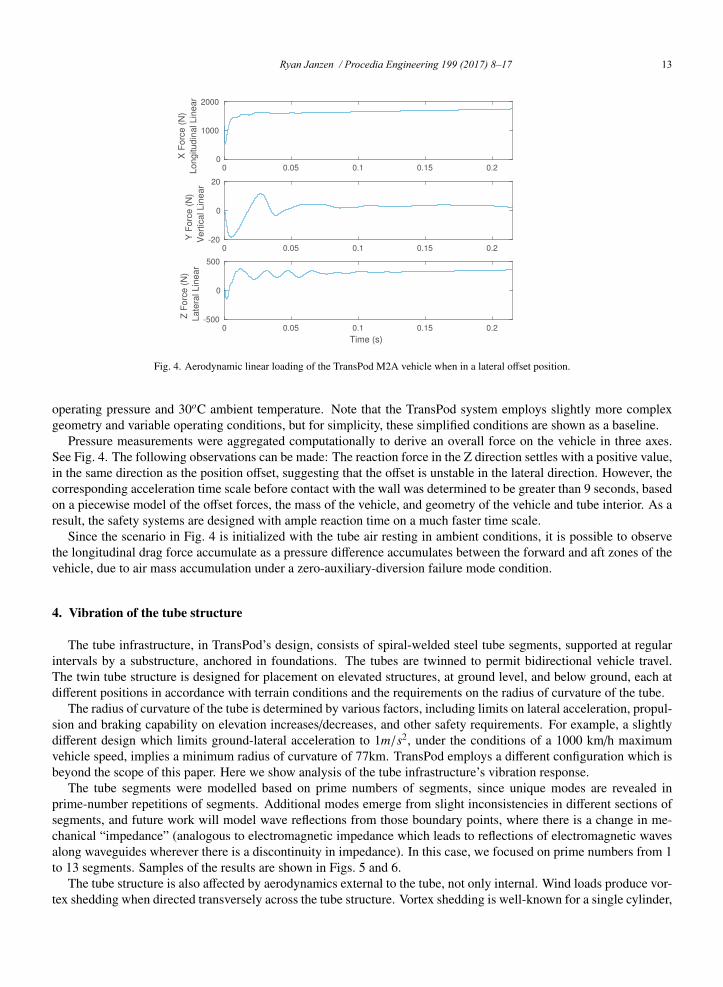
Fig. 4. Aerodynamic linear loading of the TransPod M2A vehicle when in a lateral offset position.
operating pressure and 30oC ambient temperature. Note that the TransPod system employs slightly more complexgeometry and variable operating conditions, but for simplicity, these simplified conditions are shown as a baseline.
Pressure measurements were aggregated computationally to derive an overall force on the vehicle in three axes.See Fig. 4. The following observations can be made: The reaction force in the Z direction settles with a positive value,in the same direction as the position offset, suggesting that the offset is unstable in the lateral direction. However, thecorresponding acceleration time scale before contact with the wall was determined to be greater than 9 seconds, basedon a piecewise model of the offset forces, the mass of the vehicle, and geometry of the vehicle and tube interior. As aresult, the safety systems are designed with ample reaction time on a much faster time scale.
Since the scenario in Fig. 4 is initialized with the tube air resting in ambient conditions, it is possible to observethe longitudinal drag force accumulate as a pressure difference accumulates between the forward and aft zones of thevehicle, due to air mass accumulation under a zero-auxiliary-diversion failure mode condition.
4. Vibration of the tube structure
The tube infrastructure, in TransPod’s design, consists of spiral-welded steel tube segments, supported at regularintervals by a substructure, anchored in foundations. The tubes are twinned to permit bidirectional vehicle travel.The twin tube structure is designed for placement on elevated structures, at ground level, and below ground, each atdifferent positions in accordance with terrain conditions and the requirements on the radius of curvature of the tube.
The radius of curvature of the tube is determined by various factors, including limits on lateral acceleration, propul-sion and braking capability on elevation increases/decreases, and other safety requirements. For example, a slightlydifferent design which limits ground-lateral acceleration to 1m/s2, under the conditions of a 1000 km/h maximumvehicle speed, implies a minimum radius of curvature of 77km. TransPod employs a different configuration which isbeyond the scope of this paper. Here we show analysis of the tube infrastructure’s vibration response.
The tube segments were modelled based on prime numbers of segments, since unique modes are revealed inprime-number repetitions of segments. Additional modes emerge from slight inconsistencies in different sections ofsegments, and future work will model wave reflections from those boundary points, where there is a change in me-chanical “impedance” (analogous to electromagnetic impedance which leads to reflections of electromagnetic wavesalong waveguides wherever there is a discontinuity in impedance). In this case, we focused on prime numbers from 1to 13 segments. Samples of the results are shown in Figs. 5 and 6.
The tube structure is also affected by aerodynamics external to the tube, not only internal. Wind loads produce vor-tex shedding when directed transversely across the tube structure. Vortex shedding is well-known for a single cylinder,
Ryan Janzen / Procedia Engineering 199 (2017) 8–17 13RJ / Procedia Engineering 00 (2017) 000–000 5
Fig. 3. Aerodynamics along the TransPod M2A vehicle (simplified shape), in zero-aux-bypass conditions: density, pressure, velocity, temperature.
Aerodynamic shaping of the vehicle can indeed assist in the bypass of air, but the potential for choked flow inthe bypass cross-section presents a fundamental limit. In general, there are three broad categories of aerodynamicstrategies to overcome the Kantrowitz limit for a vehicle travelling in a confined tube:
• Tube diameter sufficiently large to allow sufficient air bypass around the vehicle;• Reduced air density (pressure) inside the tube environment;• Auxiliary bypass of tube air, through the vehicle from front to back.
A disadvantage of large-diameter tube segments is that the tube dimensions greatly affect the infrastructure cost.The remaining two options provide solutions which need not require material costs continuously at each point alongthe infrastructure cross-section. Rather, reducing the air pressure merely requires vacuum pump infrastructure at dis-crete points along the line; auxiliary bypass is only required on each vehicle, much less than the entire infrastructure.
Even while reducing air pressure in the tube, it is not practical to achieve a 100% vacuum, and therefore the vehiclestill experiences a degree of air resistance. With a nonzero average air density, it is possible to combine the abovethree strategies in a proportion that can be optimized based on energy efficiency, reliability, or cost. In particular, theauxiliary bypass strategy can include a gas forcing system, such as an axial compressor, on the vehicle to drive airthrough a preferred route with reduced cross-sectional area.
In this paper, we show an example of one particular TransPod vehicle having a compressor bypass. The TransPodM2A vehicle includes an electrically-driven axial compressor, with air diversion channels which extend from front-to-back of the vehicle, first directed downward after the compressor output, then under the passenger cabin floor,then upward, and finally through a nozzle at the back of the vehicle. This is a rocket-style exhaust nozzle, with anexpansion angle similar to rocket nozzles used in a space environment having a low ambient pressure. A small amountof forward thrust is generated by this system, but the main objective is to divert air from the front of the vehicle andthereby reduce air resistance from the confined motion inside the tube.
The TransPod M2A vehicle has an exterior profile which is represented in simplified form as in Fig. 3. Here, thedynamics are simulated in a zero-compressor-force failure mode.
In transportation system design, it is important to replicate all failure modes. For example, a lateral-stabilizationfailure scenario consists of a failure of the components which hold the vehicle aligned in the centre of the tube.In this case, the vehicle would stray off-centre during a turn in the tube route. However, additionally, we wishto examine the vehicle’s stability in a loss-of-stabilization scenario—whether the offset is self-correcting or self-amplifying. Therefore, a CFD aerodynamic analysis was performed for the following conditions: vehicle positionedoff-centre by 0.325m in the +Z direction, moving at velocity vx = 300m/s, under the conditions of 100 Pa ambient
6 RJ / Procedia Engineering 00 (2017) 000–000
0 0.05 0.1 0.15 0.20
1000
2000
X
Fo
rce
(N
)
Lo
ng
itu
din
al L
ine
ar
0 0.05 0.1 0.15 0.2-20
0
20
Y F
orc
e (
N)
Ve
rtic
al L
ine
ar
0 0.05 0.1 0.15 0.2
Time (s)
-500
0
500
Z
Fo
rce
(N
)
La
tera
l L
ine
ar
Fig. 4. Aerodynamic linear loading of the TransPod M2A vehicle when in a lateral offset position.
operating pressure and 30oC ambient temperature. Note that the TransPod system employs slightly more complexgeometry and variable operating conditions, but for simplicity, these simplified conditions are shown as a baseline.
Pressure measurements were aggregated computationally to derive an overall force on the vehicle in three axes.See Fig. 4. The following observations can be made: The reaction force in the Z direction settles with a positive value,in the same direction as the position offset, suggesting that the offset is unstable in the lateral direction. However, thecorresponding acceleration time scale before contact with the wall was determined to be greater than 9 seconds, basedon a piecewise model of the offset forces, the mass of the vehicle, and geometry of the vehicle and tube interior. As aresult, the safety systems are designed with ample reaction time on a much faster time scale.
Since the scenario in Fig. 4 is initialized with the tube air resting in ambient conditions, it is possible to observethe longitudinal drag force accumulate as a pressure difference accumulates between the forward and aft zones of thevehicle, due to air mass accumulation under a zero-auxiliary-diversion failure mode condition.
4. Vibration of the tube structure
The tube infrastructure, in TransPod’s design, consists of spiral-welded steel tube segments, supported at regularintervals by a substructure, anchored in foundations. The tubes are twinned to permit bidirectional vehicle travel.The twin tube structure is designed for placement on elevated structures, at ground level, and below ground, each atdifferent positions in accordance with terrain conditions and the requirements on the radius of curvature of the tube.
The radius of curvature of the tube is determined by various factors, including limits on lateral acceleration, propul-sion and braking capability on elevation increases/decreases, and other safety requirements. For example, a slightlydifferent design which limits ground-lateral acceleration to 1m/s2, under the conditions of a 1000 km/h maximumvehicle speed, implies a minimum radius of curvature of 77km. TransPod employs a different configuration which isbeyond the scope of this paper. Here we show analysis of the tube infrastructure’s vibration response.
The tube segments were modelled based on prime numbers of segments, since unique modes are revealed inprime-number repetitions of segments. Additional modes emerge from slight inconsistencies in different sections ofsegments, and future work will model wave reflections from those boundary points, where there is a change in me-chanical “impedance” (analogous to electromagnetic impedance which leads to reflections of electromagnetic wavesalong waveguides wherever there is a discontinuity in impedance). In this case, we focused on prime numbers from 1to 13 segments. Samples of the results are shown in Figs. 5 and 6.
The tube structure is also affected by aerodynamics external to the tube, not only internal. Wind loads produce vor-tex shedding when directed transversely across the tube structure. Vortex shedding is well-known for a single cylinder,
14 Ryan Janzen / Procedia Engineering 199 (2017) 8–17RJ / Procedia Engineering 00 (2017) 000–000 7
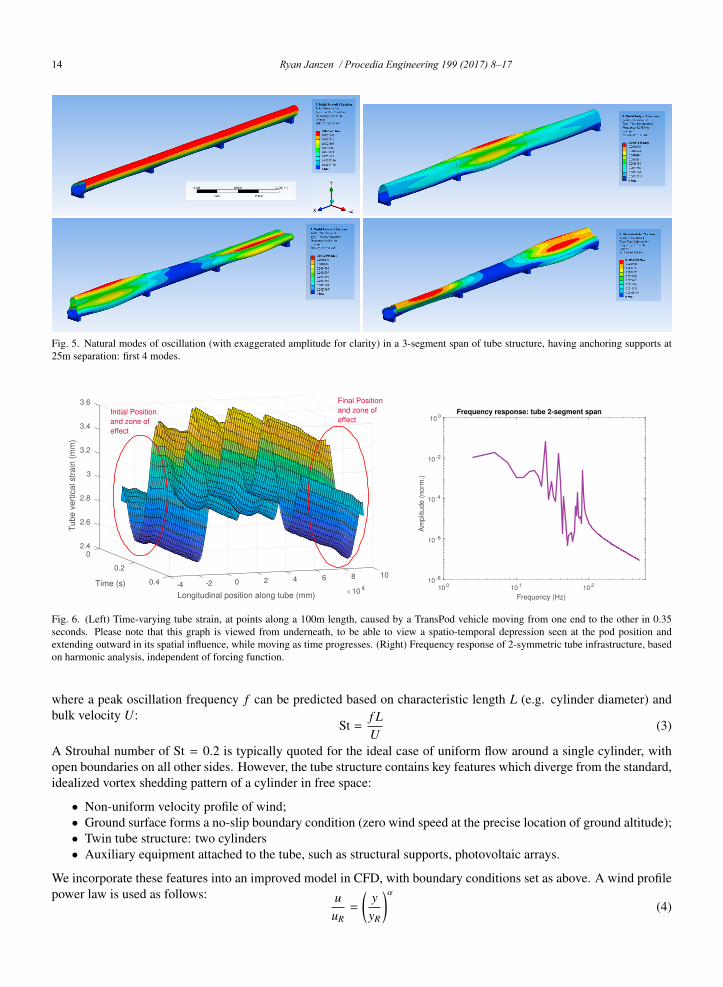
Fig. 5. Natural modes of oscillation (with exaggerated amplitude for clarity) in a 3-segment span of tube structure, having anchoring supports at25m separation: first 4 modes.
-4 -20.4 0 2 4 6
Longitudinal position along tube (mm)10 4
8 100.2
Time (s)
3.6
Tu
be
ve
rtic
al str
ain
(m
m)
3.4
3.2
0
3
2.8
2.6
2.4
Initial Position
and zone of
effect
Final Position
and zone of
effect
10 0 10 1 10 2
Frequency (Hz)
10 -8
10 -6
10 -4
10 -2
10 0A
mplit
ude (
norm
.)Frequency response: tube 2-segment span
Fig. 6. (Left) Time-varying tube strain, at points along a 100m length, caused by a TransPod vehicle moving from one end to the other in 0.35seconds. Please note that this graph is viewed from underneath, to be able to view a spatio-temporal depression seen at the pod position andextending outward in its spatial influence, while moving as time progresses. (Right) Frequency response of 2-symmetric tube infrastructure, basedon harmonic analysis, independent of forcing function.
where a peak oscillation frequency f can be predicted based on characteristic length L (e.g. cylinder diameter) andbulk velocity U:
St =f LU
(3)
A Strouhal number of St = 0.2 is typically quoted for the ideal case of uniform flow around a single cylinder, withopen boundaries on all other sides. However, the tube structure contains key features which diverge from the standard,idealized vortex shedding pattern of a cylinder in free space:
• Non-uniform velocity profile of wind;• Ground surface forms a no-slip boundary condition (zero wind speed at the precise location of ground altitude);• Twin tube structure: two cylinders• Auxiliary equipment attached to the tube, such as structural supports, photovoltaic arrays.
We incorporate these features into an improved model in CFD, with boundary conditions set as above. A wind profilepower law is used as follows: u
uR=
(yyR
)α(4)
8 RJ / Procedia Engineering 00 (2017) 000–000
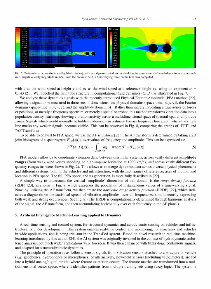
Fig. 7. Twin tube structure (indicated by black circles), with aerodynamic wind vortex shedding in simulation: (left) turbulence intensity, normal-ized; (right) velocity magnitude in m/s. From the pressure field, a time-varying force on the tube was computed.
with u as the wind speed at height y and uR as the wind speed at a reference height yR, using an exponent α =0.143 [21]. We modelled the twin tube structure in computational fluid dynamics (CFD), as illustrated in Fig. 7.
We analyze these dynamics signals with the recently-introduced Physical-Fourier-Amplitude (PFA) method [22],allowing a signal to be measured in three sets of dimensions: the physical domains (space-time: x, y, z, t), the Fourierdomains (space-time: u, v,w, f ), and the amplitude domain (A). Rather than merely indicating a time-series of forcesor positions, or merely a frequency spectrum, or merely a spatial snapshot, this method transforms vibration data into apopulation density heat-map, showing vibration activity across a multidimensional space of spectral-spatial-ampltiudezones. Signals which would normally be hidden underneath an ordinary Fourier frequency line graph, where the singleline masks any weaker signals, become visible. This can be observed in Fig. 8, comparing the graphs of “FFT” and“AF Transform”.
To be able to convert to PFA space, we use the AF transform [22]. The AF transform is determined by taking a 2Djoint histogram of a spectrogram F f ,η{s(t)}, over values of frequency and amplitude. This can be expressed as:
T AF(A, f ){s(t)} =∫{η|F=A}
dη where F = F f ,η{s(t)} (5)
PFA models allow us to coordinate vibration data, between dissimilar systems, across vastly different amplituderanges (from weak wind vortex shedding, to high-impulse levitation at 1000 km/h), and across vastly different fre-quency ranges (as were shown in Fig. 2). This allows us to merge dynamics data across diverse physical phenomenaand different systems, both in the vehicles and infrastructure, with distinct frames of reference, axes of motion, andlocation in PFA space. The full PFA space, and its generation, is more fully described in [22].
A simple way to understand the vertical “amplitude” dimension of this domain is the range density function(RDF) [23], as shown in Fig. 8, which expresses the population of instantaneous values of a time-varying signal.Now, by utilizing the AF transform, we then create the harmonic range density function (HRDF) [22], which indi-cates a diagnostic on the statistical spread of vibration amplitudes, over all frequencies, simultaneously expressingboth weak and strong occurrences. See Fig. 8. (The HRDF is computationally-determined through harmonic analysisof the signal, the AF transform, and then accumulating horizontally over each frequency in the AF plane.)
5. Artificial Intelligence Machine-Learning applied to Dynamics
A real-time sensing and control system, for structural dynamics and aerodynamic sensing on vehicles and infras-tructure, is under development. This system enables real-time control and monitoring, for structures and vehiclesin wide applications, and is being trial-run in the TransPod system. Based on novel research in real-time machine-learning introduced by this author [24], the AI system was originally invented in the context of hydrodynamic turbu-lence analysis, but much wider applications were foreseen. It was then enhanced with fuzzy-logic continuous signals,and adapted for structural/vehicle dynamics.
The principle of operation is as follows: sensor signals from vibration sensors attached to a structure or vehicle(e.g. geophones, hydrophones or microphones) or alternatively, flow-field sensors (including velocimeters), are fedinto a hybrid analog/digital circuit, where feature extraction occurs. The feature metrics are transformed into a mul-tidimensional vector space, where it identifies patterns from multiple training sets using fuzzy logic. The system is
Ryan Janzen / Procedia Engineering 199 (2017) 8–17 15RJ / Procedia Engineering 00 (2017) 000–000 7
Fig. 5. Natural modes of oscillation (with exaggerated amplitude for clarity) in a 3-segment span of tube structure, having anchoring supports at25m separation: first 4 modes.
-4 -20.4 0 2 4 6
Longitudinal position along tube (mm)10 4
8 100.2
Time (s)
3.6
Tu
be
ve
rtic
al str
ain
(m
m)
3.4
3.2
0
3
2.8
2.6
2.4
Initial Position
and zone of
effect
Final Position
and zone of
effect
10 0 10 1 10 2
Frequency (Hz)
10 -8
10 -6
10 -4
10 -2
10 0
Am
plit
ude (
norm
.)
Frequency response: tube 2-segment span
Fig. 6. (Left) Time-varying tube strain, at points along a 100m length, caused by a TransPod vehicle moving from one end to the other in 0.35seconds. Please note that this graph is viewed from underneath, to be able to view a spatio-temporal depression seen at the pod position andextending outward in its spatial influence, while moving as time progresses. (Right) Frequency response of 2-symmetric tube infrastructure, basedon harmonic analysis, independent of forcing function.
where a peak oscillation frequency f can be predicted based on characteristic length L (e.g. cylinder diameter) andbulk velocity U:
St =f LU
(3)
A Strouhal number of St = 0.2 is typically quoted for the ideal case of uniform flow around a single cylinder, withopen boundaries on all other sides. However, the tube structure contains key features which diverge from the standard,idealized vortex shedding pattern of a cylinder in free space:
• Non-uniform velocity profile of wind;• Ground surface forms a no-slip boundary condition (zero wind speed at the precise location of ground altitude);• Twin tube structure: two cylinders• Auxiliary equipment attached to the tube, such as structural supports, photovoltaic arrays.
We incorporate these features into an improved model in CFD, with boundary conditions set as above. A wind profilepower law is used as follows: u
uR=
(yyR
)α(4)
8 RJ / Procedia Engineering 00 (2017) 000–000
Fig. 7. Twin tube structure (indicated by black circles), with aerodynamic wind vortex shedding in simulation: (left) turbulence intensity, normal-ized; (right) velocity magnitude in m/s. From the pressure field, a time-varying force on the tube was computed.
with u as the wind speed at height y and uR as the wind speed at a reference height yR, using an exponent α =0.143 [21]. We modelled the twin tube structure in computational fluid dynamics (CFD), as illustrated in Fig. 7.
We analyze these dynamics signals with the recently-introduced Physical-Fourier-Amplitude (PFA) method [22],allowing a signal to be measured in three sets of dimensions: the physical domains (space-time: x, y, z, t), the Fourierdomains (space-time: u, v,w, f ), and the amplitude domain (A). Rather than merely indicating a time-series of forcesor positions, or merely a frequency spectrum, or merely a spatial snapshot, this method transforms vibration data into apopulation density heat-map, showing vibration activity across a multidimensional space of spectral-spatial-ampltiudezones. Signals which would normally be hidden underneath an ordinary Fourier frequency line graph, where the singleline masks any weaker signals, become visible. This can be observed in Fig. 8, comparing the graphs of “FFT” and“AF Transform”.
To be able to convert to PFA space, we use the AF transform [22]. The AF transform is determined by taking a 2Djoint histogram of a spectrogram F f ,η{s(t)}, over values of frequency and amplitude. This can be expressed as:
T AF(A, f ){s(t)} =∫{η|F=A}
dη where F = F f ,η{s(t)} (5)
PFA models allow us to coordinate vibration data, between dissimilar systems, across vastly different amplituderanges (from weak wind vortex shedding, to high-impulse levitation at 1000 km/h), and across vastly different fre-quency ranges (as were shown in Fig. 2). This allows us to merge dynamics data across diverse physical phenomenaand different systems, both in the vehicles and infrastructure, with distinct frames of reference, axes of motion, andlocation in PFA space. The full PFA space, and its generation, is more fully described in [22].
A simple way to understand the vertical “amplitude” dimension of this domain is the range density function(RDF) [23], as shown in Fig. 8, which expresses the population of instantaneous values of a time-varying signal.Now, by utilizing the AF transform, we then create the harmonic range density function (HRDF) [22], which indi-cates a diagnostic on the statistical spread of vibration amplitudes, over all frequencies, simultaneously expressingboth weak and strong occurrences. See Fig. 8. (The HRDF is computationally-determined through harmonic analysisof the signal, the AF transform, and then accumulating horizontally over each frequency in the AF plane.)
5. Artificial Intelligence Machine-Learning applied to Dynamics
A real-time sensing and control system, for structural dynamics and aerodynamic sensing on vehicles and infras-tructure, is under development. This system enables real-time control and monitoring, for structures and vehiclesin wide applications, and is being trial-run in the TransPod system. Based on novel research in real-time machine-learning introduced by this author [24], the AI system was originally invented in the context of hydrodynamic turbu-lence analysis, but much wider applications were foreseen. It was then enhanced with fuzzy-logic continuous signals,and adapted for structural/vehicle dynamics.
The principle of operation is as follows: sensor signals from vibration sensors attached to a structure or vehicle(e.g. geophones, hydrophones or microphones) or alternatively, flow-field sensors (including velocimeters), are fedinto a hybrid analog/digital circuit, where feature extraction occurs. The feature metrics are transformed into a mul-tidimensional vector space, where it identifies patterns from multiple training sets using fuzzy logic. The system is

16 Ryan Janzen / Procedia Engineering 199 (2017) 8–17RJ / Procedia Engineering 00 (2017) 000–000 9
0 20 40 60 80−10000
−5000
0
5000
Time (s)
Sig
nal (P
a)
Signal
−10000 −5000 0 50000
0.2
0.4
0.6
0.8Range Density Function (RDF)
qR
DF
(q)
0 20 40 60 800
1
2
3
4
5Spectrogram
Time (s)
Fre
quency (
Hz)
0 1 2 3 4 50
10
20
30
40
50FFT
Frequency (Hz)
Am
plit
ude (
dB
: 1 P
a)
0 1 2 3 4 5
0
50
100
AF Transform
Frequency (Hz)
Am
plit
ude (
dB
: 1 P
a)
0
50
100
0 0.005 0.01 0.015 0.02
Harmonic Range Density Function (HRDF)
A (
dB
: 1 P
a)
HRDF(A)0 1 2 3 4 5
x 10−3
−40
−20
0
20
40
60
80
100
AF Transform (Log scale amplitude)
Frequency (kHz)
Am
plit
ud
e (
dB
: 1
Pa
)
Fig. 8. PFA analysis of tube wind load dynamics: (left) range density function and process to achieve AF transform; (right) AF transform of windvortex shedding signal.
trained in the lab or in the field, to adapt to the particular sensors and physical phenomena, and trained with a certaincontrol signal response, as desired. The system can be used to control vehicle dynamics, and also monitor structuraldynamics performance, interfaced with control systems as desired. Inside, this system is based on a hybrid ana-log/digital design with multi-stage cascaded feature extraction. Low-power high-bandwidth signal processing circuitsare complemented by computation on a microprocessor, to interpret salient features of the signals.
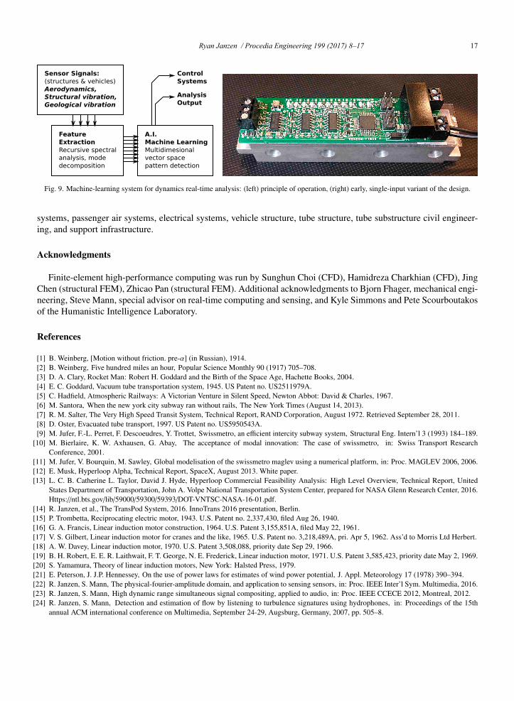
By splitting into a hybrid circuit design, the system can be made extremely compact, power efficient, and able tobe embedded on vehicle fuselages and even civil-engineering structures. It is designed to be capable of self-sufficientoperation on battery power or even solar power, based on low-power efficient computation. One variant of the originalsystem was shrunk into a miniaturized circuit design by Kyle Simmons and Pete Scourboutakos of the HumanisticIntelligence Laboratory, with Ryan Janzen. (Fig. 9)
The original technology [24] was successfully demonstrated with a challenging test case: it was able to determinethe temperature of a fluid, based on the sound that fluid made while flowing. Further work is ongoing to adapt thissystem to structural dynamics detection and supersonic/subsonic vehicle aerodynamics. Background information canbe seen at: http://eyetap.org/sensing/
6. Conclusion
This paper discussed an overview of the TransPod ultra-high-speed system, the history and challenges tube-basedtransportation, and benefits in terms of transportation engineering, speed, departure frequency, and efficiency. Se-lected dynamics of the tube structure and vehicle interaction were examined, particularly dynamic forces at play inaerodynamics of the vehicle travel inside the tube, and natural vibration forces on the tube itself.
The TransPod system is a large-scale engineering project, with development continuing on all elements of the ve-hicles and infrastructure, including propulsion systems, levitation systems, guidance and control, signalling, thermal
10 RJ / Procedia Engineering 00 (2017) 000–000
Sensor Signals:(structures & vehicles)Aerodynamics,Structural vibration, Geological vibration
Feature ExtractionRecursive spectral analysis, mode decomposition
A.I.Machine LearningMultidimesional vector space pattern detection
Control Systems
AnalysisOutput
Fig. 9. Machine-learning system for dynamics real-time analysis: (left) principle of operation, (right) early, single-input variant of the design.
systems, passenger air systems, electrical systems, vehicle structure, tube structure, tube substructure civil engineer-ing, and support infrastructure.
Acknowledgments
Finite-element high-performance computing was run by Sunghun Choi (CFD), Hamidreza Charkhian (CFD), JingChen (structural FEM), Zhicao Pan (structural FEM). Additional acknowledgments to Bjorn Fhager, mechanical engi-neering, Steve Mann, special advisor on real-time computing and sensing, and Kyle Simmons and Pete Scourboutakosof the Humanistic Intelligence Laboratory.
References
[1] B. Weinberg, [Motion without friction. pre-α] (in Russian), 1914.[2] B. Weinberg, Five hundred miles an hour, Popular Science Monthly 90 (1917) 705–708.[3] D. A. Clary, Rocket Man: Robert H. Goddard and the Birth of the Space Age, Hachette Books, 2004.[4] E. C. Goddard, Vacuum tube transportation system, 1945. US Patent no. US2511979A.[5] C. Hadfield, Atmospheric Railways: A Victorian Venture in Silent Speed, Newton Abbot: David & Charles, 1967.[6] M. Santora, When the new york city subway ran without rails, The New York Times (August 14, 2013).[7] R. M. Salter, The Very High Speed Transit System, Technical Report, RAND Corporation, August 1972. Retrieved September 28, 2011.[8] D. Oster, Evacuated tube transport, 1997. US Patent no. US5950543A.[9] M. Jufer, F.-L. Perret, F. Descoeudres, Y. Trottet, Swissmetro, an efficient intercity subway system, Structural Eng. Intern’l 3 (1993) 184–189.
[10] M. Bierlaire, K. W. Axhausen, G. Abay, The acceptance of modal innovation: The case of swissmetro, in: Swiss Transport ResearchConference, 2001.
[11] M. Jufer, V. Bourquin, M. Sawley, Global modelisation of the swissmetro maglev using a numerical platform, in: Proc. MAGLEV 2006, 2006.[12] E. Musk, Hyperloop Alpha, Technical Report, SpaceX, August 2013. White paper.[13] L. C. B. Catherine L. Taylor, David J. Hyde, Hyperloop Commercial Feasibility Analysis: High Level Overview, Technical Report, United
States Department of Transportation, John A. Volpe National Transportation System Center, prepared for NASA Glenn Research Center, 2016.Https://ntl.bts.gov/lib/59000/59300/59393/DOT-VNTSC-NASA-16-01.pdf.
[14] R. Janzen, et al., The TransPod System, 2016. InnoTrans 2016 presentation, Berlin.[15] P. Trombetta, Reciprocating electric motor, 1943. U.S. Patent no. 2,337,430, filed Aug 26, 1940.[16] G. A. Francis, Linear induction motor construction, 1964. U.S. Patent 3,155,851A, filed May 22, 1961.[17] V. S. Gilbert, Linear induction motor for cranes and the like, 1965. U.S. Patent no. 3,218,489A, pri. Apr 5, 1962. Ass’d to Morris Ltd Herbert.[18] A. W. Davey, Linear induction motor, 1970. U.S. Patent 3,508,088, priority date Sep 29, 1966.[19] B. H. Robert, E. E. R. Laithwait, F. T. George, N. E. Frederick, Linear induction motor, 1971. U.S. Patent 3,585,423, priority date May 2, 1969.[20] S. Yamamura, Theory of linear induction motors, New York: Halsted Press, 1979.[21] E. Peterson, J. J.P. Hennessey, On the use of power laws for estimates of wind power potential, J. Appl. Meteorology 17 (1978) 390–394.[22] R. Janzen, S. Mann, The physical-fourier-amplitude domain, and application to sensing sensors, in: Proc. IEEE Inter’l Sym. Multimedia, 2016.[23] R. Janzen, S. Mann, High dynamic range simultaneous signal compositing, applied to audio, in: Proc. IEEE CCECE 2012, Montreal, 2012.[24] R. Janzen, S. Mann, Detection and estimation of flow by listening to turbulence signatures using hydrophones, in: Proceedings of the 15th
annual ACM international conference on Multimedia, September 24-29, Augsburg, Germany, 2007, pp. 505–8.
Ryan Janzen / Procedia Engineering 199 (2017) 8–17 17RJ / Procedia Engineering 00 (2017) 000–000 9
0 20 40 60 80−10000
−5000
0
5000
Time (s)
Sig
nal (P
a)
Signal
−10000 −5000 0 50000
0.2
0.4
0.6
0.8Range Density Function (RDF)
q
RD
F(q
)
0 20 40 60 800
1
2
3
4
5Spectrogram
Time (s)
Fre
quency (
Hz)
0 1 2 3 4 50
10
20
30
40
50FFT
Frequency (Hz)
Am
plit
ude (
dB
: 1 P
a)
0 1 2 3 4 5
0
50
100
AF Transform
Frequency (Hz)
Am
plit
ude (
dB
: 1 P
a)
0
50
100
0 0.005 0.01 0.015 0.02
Harmonic Range Density Function (HRDF)
A (
dB
: 1 P
a)
HRDF(A)0 1 2 3 4 5
x 10−3
−40
−20
0
20
40
60
80
100
AF Transform (Log scale amplitude)
Frequency (kHz)
Am
plit
ud
e (
dB
: 1
Pa
)
Fig. 8. PFA analysis of tube wind load dynamics: (left) range density function and process to achieve AF transform; (right) AF transform of windvortex shedding signal.
trained in the lab or in the field, to adapt to the particular sensors and physical phenomena, and trained with a certaincontrol signal response, as desired. The system can be used to control vehicle dynamics, and also monitor structuraldynamics performance, interfaced with control systems as desired. Inside, this system is based on a hybrid ana-log/digital design with multi-stage cascaded feature extraction. Low-power high-bandwidth signal processing circuitsare complemented by computation on a microprocessor, to interpret salient features of the signals.
By splitting into a hybrid circuit design, the system can be made extremely compact, power efficient, and able tobe embedded on vehicle fuselages and even civil-engineering structures. It is designed to be capable of self-sufficientoperation on battery power or even solar power, based on low-power efficient computation. One variant of the originalsystem was shrunk into a miniaturized circuit design by Kyle Simmons and Pete Scourboutakos of the HumanisticIntelligence Laboratory, with Ryan Janzen. (Fig. 9)
The original technology [24] was successfully demonstrated with a challenging test case: it was able to determinethe temperature of a fluid, based on the sound that fluid made while flowing. Further work is ongoing to adapt thissystem to structural dynamics detection and supersonic/subsonic vehicle aerodynamics. Background information canbe seen at: http://eyetap.org/sensing/
6. Conclusion
This paper discussed an overview of the TransPod ultra-high-speed system, the history and challenges tube-basedtransportation, and benefits in terms of transportation engineering, speed, departure frequency, and efficiency. Se-lected dynamics of the tube structure and vehicle interaction were examined, particularly dynamic forces at play inaerodynamics of the vehicle travel inside the tube, and natural vibration forces on the tube itself.
The TransPod system is a large-scale engineering project, with development continuing on all elements of the ve-hicles and infrastructure, including propulsion systems, levitation systems, guidance and control, signalling, thermal
10 RJ / Procedia Engineering 00 (2017) 000–000
Sensor Signals:(structures & vehicles)Aerodynamics,Structural vibration, Geological vibration
Feature ExtractionRecursive spectral analysis, mode decomposition
A.I.Machine LearningMultidimesional vector space pattern detection
Control Systems
AnalysisOutput
Fig. 9. Machine-learning system for dynamics real-time analysis: (left) principle of operation, (right) early, single-input variant of the design.
systems, passenger air systems, electrical systems, vehicle structure, tube structure, tube substructure civil engineer-ing, and support infrastructure.
Acknowledgments
Finite-element high-performance computing was run by Sunghun Choi (CFD), Hamidreza Charkhian (CFD), JingChen (structural FEM), Zhicao Pan (structural FEM). Additional acknowledgments to Bjorn Fhager, mechanical engi-neering, Steve Mann, special advisor on real-time computing and sensing, and Kyle Simmons and Pete Scourboutakosof the Humanistic Intelligence Laboratory.
References
[1] B. Weinberg, [Motion without friction. pre-α] (in Russian), 1914.[2] B. Weinberg, Five hundred miles an hour, Popular Science Monthly 90 (1917) 705–708.[3] D. A. Clary, Rocket Man: Robert H. Goddard and the Birth of the Space Age, Hachette Books, 2004.[4] E. C. Goddard, Vacuum tube transportation system, 1945. US Patent no. US2511979A.[5] C. Hadfield, Atmospheric Railways: A Victorian Venture in Silent Speed, Newton Abbot: David & Charles, 1967.[6] M. Santora, When the new york city subway ran without rails, The New York Times (August 14, 2013).[7] R. M. Salter, The Very High Speed Transit System, Technical Report, RAND Corporation, August 1972. Retrieved September 28, 2011.[8] D. Oster, Evacuated tube transport, 1997. US Patent no. US5950543A.[9] M. Jufer, F.-L. Perret, F. Descoeudres, Y. Trottet, Swissmetro, an efficient intercity subway system, Structural Eng. Intern’l 3 (1993) 184–189.
[10] M. Bierlaire, K. W. Axhausen, G. Abay, The acceptance of modal innovation: The case of swissmetro, in: Swiss Transport ResearchConference, 2001.
[11] M. Jufer, V. Bourquin, M. Sawley, Global modelisation of the swissmetro maglev using a numerical platform, in: Proc. MAGLEV 2006, 2006.[12] E. Musk, Hyperloop Alpha, Technical Report, SpaceX, August 2013. White paper.[13] L. C. B. Catherine L. Taylor, David J. Hyde, Hyperloop Commercial Feasibility Analysis: High Level Overview, Technical Report, United
States Department of Transportation, John A. Volpe National Transportation System Center, prepared for NASA Glenn Research Center, 2016.Https://ntl.bts.gov/lib/59000/59300/59393/DOT-VNTSC-NASA-16-01.pdf.
[14] R. Janzen, et al., The TransPod System, 2016. InnoTrans 2016 presentation, Berlin.[15] P. Trombetta, Reciprocating electric motor, 1943. U.S. Patent no. 2,337,430, filed Aug 26, 1940.[16] G. A. Francis, Linear induction motor construction, 1964. U.S. Patent 3,155,851A, filed May 22, 1961.[17] V. S. Gilbert, Linear induction motor for cranes and the like, 1965. U.S. Patent no. 3,218,489A, pri. Apr 5, 1962. Ass’d to Morris Ltd Herbert.[18] A. W. Davey, Linear induction motor, 1970. U.S. Patent 3,508,088, priority date Sep 29, 1966.[19] B. H. Robert, E. E. R. Laithwait, F. T. George, N. E. Frederick, Linear induction motor, 1971. U.S. Patent 3,585,423, priority date May 2, 1969.[20] S. Yamamura, Theory of linear induction motors, New York: Halsted Press, 1979.[21] E. Peterson, J. J.P. Hennessey, On the use of power laws for estimates of wind power potential, J. Appl. Meteorology 17 (1978) 390–394.[22] R. Janzen, S. Mann, The physical-fourier-amplitude domain, and application to sensing sensors, in: Proc. IEEE Inter’l Sym. Multimedia, 2016.[23] R. Janzen, S. Mann, High dynamic range simultaneous signal compositing, applied to audio, in: Proc. IEEE CCECE 2012, Montreal, 2012.[24] R. Janzen, S. Mann, Detection and estimation of flow by listening to turbulence signatures using hydrophones, in: Proceedings of the 15th
annual ACM international conference on Multimedia, September 24-29, Augsburg, Germany, 2007, pp. 505–8.