
Transparent Web Caching Minimum Response
114
Transparent Web Caching with Minimum Response Time By Qing Zou A thesis submitted to the Department of the Computing and Monnation Science in conformity with the requirements for the degree of the Master of Science Queen' s University Kingston, Ontario, Canada January 2002 Copyright O Qing Zou, 2002
Transcript of Transparent Web Caching Minimum Response

Transparent Web Caching with Minimum Response Time
By Qing Zou
A thesis submitted to the
Department of the Computing and Monnation Science
in conformity with the requirements
for the degree of the Master of Science
Queen' s University
Kingston, Ontario, Canada
January 2002
Copyright O Qing Zou, 2002

uisitions and 3- Acquisiüons et Bi iographic Services senrices bibliographiques
The author has graated a non- exclusive licence allowing the National Li'brary of Canaâa to repfoduce, lom, distriïute or seii copies of this thesis in microf- paper or electronic formats.
The author retains ownership of the copyright in this thesis. Neither the thesis nor substantial extracts fkom it may be printed or otherwise reproduced without the author's permission.
L'auteur a accordé une licence non exclusive permettant à la Bibliothèque nationale du Canada de reproduire, prêter, distriiuer ou vendre des copies de cette thèse sous la forme de microfiche/nIm, de reproduction sur papier ou sur format électronique.
L'airteur conserve la prophété du droit d'auteur qui protège cette thèse. Ni la thèse ni des extraits substantiels de celle-ci ne doivent être imprimés ou autrement reproduits sans son autorisation.

Abstract
Distributed Web caching systerns aiiow better load sharing and more fault tolerance in
Web caching systerns. Layer 5 switching-based transparent Web caching schemes
intercept H ï T P requests and redirect them according to their content. Employment of
these schemes in distributed Web caching systerns provides balanced server workload,
reduced response t h e and improved cache sharing. However, none of the existing
schemes attempt to minirnize the HTTP request response the .
In this thesis, we propose a Minimum Response Tine (MRT) Layer 5 switching-based
Web caching scheme for distributed Web caching systems. MRT distinguishes non-
cacheable requests from cacheable requests based on IFITP request header. It
inteugently redirects cacheable requests to the cache server with the minimum HITE'
request response tirne based on the information about cache server content. cache server
workload, Web server workload and network latency. MRT extends ICP to support the
communication between cache servers and Layer 5 switches. The MRT heuristic is a
solution to optimize the performance of the distributed Web caching.
A nurnber of simulation experiments are conducted under Werent H ï T P request
intensities, net work latenc y factors. object expiration time values and number of
cooperating cache servers. Simulation results show t hat MRT outperforms existing
switc hing-based Web cac hing SC hernes. narnely Content, Workload, R n and LB-L5 in
terrns of HTTP request response the.

Acknowledgements
I would iike to express my gratitude to my supervisors Professor Patrick Martin and
Professor Hossam Hassanein, for their excellent guidance, great advice and support.
1 would k e to thank Wendy Powley and al1 the other members in the Database System
Laboratory and the Telecommunications Research Laboratory at Queen' s University for
t hei. suggestions, assistance, comments and fiiendship.
Special thanks to my husband Gang, for his selfless support and great advice. Thanks to
Jasrni John and Hongzhi Li at the Computer Science Department, Queen's University for
their generous help. Thanks to Zhenggang Liang for help with the simulation code.
Finally, 1 would also like to thank the Department of Computing and Information Science
at Queen's University for offering me such an invaluable opportunity to pursue my
Master's Degree. The financial support provided by Communications and Information
Technology Ontario (CITO) and Kingston Software Factory is appreciated.

Table of Contents
Chapter 1 htduction.w...wwwwwwww .................................................................................... 1
Chapter 2 Related Work o w w w w w w w o w w w o w w w w w o w w o w w o o w w o w w m w o w o w m w w œ w w w w w o w w w w w w w o w o w o w w w w o w w w w w w w w w w w w w w 6
.......................................................... 2.1 Hierarchical and Distributed Web Caching 7
........................ 2.2 Client-Initiated Selection Algonthms .... ................................. 10 .............................................. ................... 2.2.1 Minimum Number of Hops ..... 10
................................................ .................... 2.2.2 Minimum Round Trip T h e .. 11 .............................................................. 2.2.3 Minimum H'ITP Request Latency 13
...................................................... 2.2.4 Hybrid Approach of Bandwidth and R ï T 13
........................ 2.3 Switch Selection Algonthms ... ................................................. 14 2.3.1 Content-Based Selection ......................................................................... 16
............................................................................ 2.3.2 Workioad-Based Selection 16 .................................................................................... 2.3.3 RTT-Based SeIection 17
................................................. ................................. 2.3.4 LB-LS Selection ..... 18
2.4 Summary ............................................................................................................. 19
Chapter 3 Minimum Respoose Time Scheme ww........www.............................. w.wwwwwwwwwwœwwwww2 1
.......................................................................................... 3.1 Overview of the MRT 22 ...................................................... .................................. 3.1.1 Content Checking .. 23
................................................................................. 3.1.2 Cache Server Selection -25 ................................................. ......................... 3.1.3 MRT Routing Scheme ... 32
.................................................................. 3.2 Detailed Description of MRT Scheme 34 ...................................... 3 .2.1 Extended ICP Messages ..
......................................................................... 3.2.2 Extended Information Table -37 3.2.3 Routing Mechanisrn of MRT ......................................................................... 38
Chapter 4 Peiiormance Evaluation .,...,.wwwwww..wwwmmw.www.ww.wwwwwœoœo~ ................................. =.42
4.1 Simulation Mode1 ................................................................................................ 43 4.1.1 Network Mode1 ............................................................................................ .43
............................................. ........................ ... 4.1.2 Network Latency Mode1 .. .. 44 .......................................................................................... 4.1.3 Workload Mode1 -46
........................................................................... 4.1.4 Validation Checking Mode1 47 4.1.6 Simulation Parameter Setting ................... ...... .......................................... 49

............................................. 4.2 Content. Workload. RTT and LB-LS Schemes 5 1 .................................................................................... 4.2.1 The Content Scheme .5 1
................................. ................. 4.2.2 The Workload Scheme ...,. 5 1 .......................................................................................... 4.2.3 The RTï Scheme 52
.................................................................................. 4.2.4 The LB-LS Scheme -52
4.3 Performance Metrics ......................................................................................... -53
4.4 Simulation Results ............................. .... ..... .. ......................................... 54 ....................................................................... 4.4.1 Raw-trace Driven Simulations 55
.................................................... 4.4.2 Controlled-Trace With Balanced Requests 60 ............................................. 4.4.3 Controlled-Trace Wit h Unbalanced Requests ...69
................................................................. 4.4.4 Effect of Number of Cache Server 73
4.5 Summary ............................................................................................................. 77
5.1 Contributions ....................................................................................................... 79
......................................................................................................... 5.2 Future Work 80

List of Figures
....................................... FIGURE 2.1 H~ERARCHICAL ARCH~IECTLTRE FOR WEB CACHING 8
........................................................... FIGURE 3.2 FALSE Hrr RATES -27 ............................................................... Fmm 3.3 A CACHE-HTT REQUEST IN MRT -29 ................................................... FIGURE 3 -4 A CACHE-M~SS REQUEST IN MRT 3 1
FIGURE 3.5 CACHE SERVER PROCESSING TiME AND NIMBER OF CONCURRENT REQUESTS .............................................................................................................................. 32
FIGURE 3.6 ICP MESSAGE FORMAT .................................... ... ........................................ -34 ............................................... . FIGURE 3 7 RIE FORMAT OF ICP_UPDATE_CONTENT 35
..................................... FIGURE 3.8 THE FORMAT OF ICPCPUPDATE_CONTENTNTACK 36 ............................................. F~GURE 3.9 nlE FORMAT OF ICPQUERY-WORKLO AD 36
......................................... FIGURE 3.10 THE FORMAT OF ICPUPDATEJORKLOAD 36 FIGURE 3.1 1 CACHESERVERARRAY INFORMATION TABLE .................... .... ................. -37
..................................................................... FIGURE 4.2 NEIWORK LATENCY MODEL -45 ......................................................................... RGURE 4.3 HTTP REQUEST INIENsm -55
FIGURE 4.4 RESPONSE TIME AT ~ T E N C Y FACTOR = ~ M S .............................................. -57 ........................................ FIGURE 4.5 ]RESPONSE TIME AT ~ T E N C Y FACTOR = 7 5 ~ S -58
FIGURE 4.6 RE~PONSE TIME AT LATENCY FACTOR = 125 MS ......................................... -59 FIGURE 4.7 AVERAGE RESPONSE Tma VERSUS H T P REQUEST INTENsm .................... 63
................ FIGURE 4.8 AVERAGE ~ P O N S E TIME VERSUS NEIWORK LATENCY FACTOR -67
FIGURE 4 . f 0 WORKLOAD AND AVERAGE RESPONSE TIME .............................................. -73 FIGURE 4.1 1 AVERAGE RESPONSE T t m VERSUS THE NUMBER OF CACHE SERVERS ........ 76
.............................................. . FIGURE B 1 PSEUDO CODE FOR LAYER 5 SWITCH IN MRT 95 ..................................... FIGURE B.2 PSEUDO CODE FOR m0XY CACHE SERVER IN m T 97
.................................................... FIGURE B -3 PSEUDO CODE FOR WEB SERVER IN MRT -98

List of Tables
...................................................................................................... TABLE 3.1 SYMBOLS 23 ................................................................................................ TAJXE 3.2 ICP OPCODE -35
............................................................................... TABLE 4.1 PARAMEERS FOR LINK -50 ........................................................................ TABLE 4.2 PAWMEIERs FOR SWfIÇHES -50
.................................................................... TABLE 4.3 PARAMETERS FOR WEB SERVER -50 ............................................................... TABLE 4.4 PARAMET~ERS FOR CACHE SERIERS -50

List of Acronyms
Cornmon Gateway Interface
CSS 1 Content Smart Switch
HTTP Hypertext Transfer Rotocol
ICMP / Intemet Control Message RotocoI
ICP Internet Cache Protocol
LB-LS Load Balancing Layer 5 switching-based transparent
NLANR National Laboratory for Applied Network Research
MRT 1 Minimum Responw Time 1
RTT Round Trip Tirne
TCP 1 Transmission Control Protocol
UDP User Datagram Protocol
URL Uniform Resource Locator
W3C World Wide Web Consortium
vii

Chapter 1 : Introduction 1
Chapter 1
Introduction
The rapidly increasing number of Web applications, coupled with the rapidly increasing
number of documents accessible by Web clients, has resulted in an explosive increase in
Web t r a c expressed both in tenns of H ï T P requests and H T ï P replies. H ï T P Web
tratnc has grown to account to 75-80% of aii Intemet t r a c [Il. There is no indication
that this increase wiU abate in the near future. In fact, the number of Web users keeps
increasing and the Web is used in ever more different ways to access a wide variety of
text, stiil images, audio and video documents. This popularity is raising an urgent need
for solutions ajmed at improving the quality of the service provided by the Web.
Web caching [l] [2] is one of the most popular solutions to the problem mentioned
above. It is a technique that uses caches over the Intemet for replication of the most
frequently accessed data. Various approaches have been examined in order to increase
the performance of Web caching. These include the use of large caches and of more
efficient cache management techniques. Ho wever, the effectiveness of a single cache
remah poor as it is, in general, no bigher than 40% [3]. Furthemiore, the use of large

Chapter 1: Introduction 2
caches raises financial and technical problerns. Other efforts have focused on pre-
fetctung of data to caches but the resulting t r a c overhead is too costly 141. Another way
to increase Web caching performance is to expand solutions fkom the level of a single
cache to the level of a set of cooperating caches. Cache cooperation provides a
mechanism to share documents among caches and to share one cache among a nwnber of
clients [SI 161 [7] [SI.
The most popular types of cooperative cache systems are the hierarchical and the
distributed systems, which are both implemented by the Squid software [l] 193 as part of
the Harvest project [IO]. Several Web caching schernes are deployed by Squid to support
cache cooperation. Intemet Cache Protocol (ICP) [Il] is employed to exchange the
messages between cache servers. A Bloom Fiiter [12] is used in Squid to represent the
cache content compactly. Ln this type of cooperation, approaches for inter-proxy
cooperation try to rnaximize the global hit ratios. A Web client's local proxy redirects
requests to one of its cooperative cache servers when it is a cache-rniss on the local cache
server. The redirection is based on the query results of the contents of the cooperative
cache servers.
Traditional hierarc hical Web cac hing systems [ 11 [9] have several draw backs. Shared
higher-level cache servers may be too far away fiom the client. Cache misses are
signincantly delayed by having to traverse the hierarchy. As weli, redundant data are
stored on higher-level cache servers and the higher-level cache servers may becorne a
bottleneck. Distributed Web caching systems [ 11 [9] [ 131 1141 [ 151 [16] rely on replicated

Chapter 1: Introduction 3 - -- -- - -- -
objects and services to improve performance and reliability. There are no hierarchies
among cache servers. AU cache servers are employed at the same level. So distributed
Web caching systems overcom the drawbacks of hierarchical Web caching systems.
Moreover, they have better fault tolerance, distriiution of server loads and improvement
of client performance by bringing cache servers closer to Web clients.
In both traditional hierarchical or distributed Web caching system, the redirection of
HTTP requests is done by cache servers. There are cases in which copies of objects in
sorne distant cache servers may not be worth fetching. Instead the original Web server
itself may be a better choice. Sometimes copies in a heavily loaded cache rnay be costly
to fetch and instead a Lightly loaded cache may be a better choice. It is dificult for a
cache server to colect and process the load information of all the cooperative cache
servers and network load information. The packet processing hinctions and packet
forwarding functions may not be efficient if perfonned at cache servers.
Recently, a new type of Web caching technique has emerged. It is cded switching-based
transparent Web caching [17] [18]. A switch sits in the data path between the Web
clients and the server cluster. It intercepts the Web traffic and transparently redirects the
HTTP requests to different cache servers or to the Web server. Transparent Web caching
makes the configuration of the caching sptem easier. Switches can rapidly process and
forward the packet S. This switc hing-based transparent Web cac hing technique can use
content-aware Layer 5 switches in a distnbuted Web caching system with enhanced
cache cooperation 1191 [20] [21] [22]. The switches perform content checking based on

Chapter 1 : Introduction 4
Layer 5 header information of the HM'P request packets. A HTTP request is redirected
by switches to the cache server that can best service the request.
From the perspective of the Web clients, the request response time is an essential
component of quality of service. However, fluctuations in network congestion and server
load make it dificult to collect the information and to predict response times. In the
existing switching-based transparent Web caching system, the switch uses several
performance estimators to approximate the HTTP request response time. For example, a
ping probe [23] masures current network latency but does not masure server workload.
Another example is Cisco CSS 1 1000 [22], which requires the cooperative cache servers
be within the same LAN. Z. Liang proposes a Load Balancing Layer 5 switching-based
transparent Web caching scheme (LB-LS) [20]. LB-L5 considers both workload and
network latency, but LB-L5 has one main drawback in that it cannot guarantee minimum
response time for Web requests.
In this thesis, we propose the Minimum Response Time (MRT) switching-based Web
caching scheme. The main goals of our research are:
To propose a solution to optimize the performance of distributed switching-based
transparent Web caching systems. The proposed scheme should minimize the EFITP
request response time and balance the workload among the caches based on a
combination of request content, cache server content, network latency and server
workload.

Chapter 1 : Introduction
O To deveiop a trace driven simulation to evaluate the performance of the proposed
scheme.
The rest of the thesis is organized as foiiows. Chapter 2 surveys existing work on
distributed Web caching systerm. In Chapter 3. we descni the proposed MRT scheme.
Simulation results and analysis are reported in Chapter 4. Finaiiy, in Chapter 5 we
conclude the thesis, List the contn'butions of our work and discuss future research
directions.

Chapter 2: Related Work 6
Chapter 2
Related Work
Web caching improves the quality of the semce provided by the Intemet. A single cache,
however, has a h i t e size and there is a b i t to the number of objects that c m be cached.
A group of cache servers can be used to realize cache cooperation. The two most popular
types of cooperative cache systems are the hierarchical and the distributed systems. In
hierarchical Web caching architecture, cache servers are placed at multipie levels of the
network. On the other hand, in distributed caching architecture, caches are placed at the
bottom levels of the network and there are no intermediate caches. Such distributed
systems rely on replicated objects at different locations and services to improve
performance and reliability. The design of efficient server selection algorithms is critical
for distributed Web caching sc hemes.
This chapter presents a literature review of server selection algonthrns in distributed Web
cachiG systems. Section 2.1 gives a bnef introduction to the hierarchical and the
distributed Web caching modeis. The server selection rnethods f d into three categones:

Chapter 2: Reiated Work 7
client-initiated [23] [24] [25] 1261 [27], switch-based [17] 1181 1191 [20] [21] [22] and
semer-initiated [28] [29] methods (depending on who makes the selection). Both client-
initiated and switch-based approaches are aimed at a group of servers that are
heterogeneous. Section 2.2 discusses current client-side selection algonthms. Section 2.3
presents selection methods that rely on network switches, which are the focus of our
work. Switches choose arnong the interfaces by deciding which is "best", where best is
dehed by request contents and the switch meincs. In semer-initiated methods, the
servers decide where to send the requests. The server side algorithms are used for Web
server clusters, which typically contain members with similar resources and a shared
local network. As they do not directly pertain to the work in this thesis, they are not
discussed further. Finally a summary is given in section 2.4.
2.1 Hierarchical and Distributed Web Caching
Hierarchical Web caching is one form of cooperation among cache servers. Traditional
hierarchical cache server architectures such as Squid [ 1 ] 191 define parent-sibling
relationships among cache servers. A parent cache server is essentially one level up in a
cache hierarchy. A sibling cache server is on the same level. Each cache server in the
hierarchy is shared by a group of clients or by a group of children cache servers, as
show in Figure 2.1.

Chapter 2: Related Work 8
Figure 2.1 Hierarchical Architecture for Web Caching
Data access proceeds as foilows: if the lowest-level cache server contains the data
requested by a client, it sends the data to the client, othenvise, the cache server asks each
of its siblings for the data. If none of the siblings possess the data, then the cache server
sends a request to its parent. This process recursively continues up the hierarchy until the
data is located or the root cache server fetches the data from the Web server. The cache
servers then send the data down the hierarchy and each cache dong the path stores the
data.
Traditional cache hierarchies have severai problems. Fust, a request rnay have to travel
rnany hops in a cache hierarchy directory to get to the data, and the data rnay traverse
several hops back to get to the ciients. Second, cache misses are significantly delayed by
having to traverse the hierarchy. Third, there is little sharing of data among caches.
Fourth, shared higher-level cache servers may be too far away from the client and the
tirne for the object to reach the client is simply unacceptable.

Chapter 2: Related Work 9 -- ~ -
Distributed Web caching aüows the distribution of caching proxies geographically over
large distances and attempts to overcome some of the drawbacks of traditionai
hierarchical Web caching. Cache servers are organized into cache clusters with no
definite hierarchy among them, as shown in Figure 2.2. A &vice, such as a switch or a
locai cache of the client cluster, sits between the client cluster and the cache server
cluster.
Figure 2.2 Distributed Architecture for Web Caching
Data access proceeds as foliows: if a local cache server contains the data requested by a
client, it sends the data to the client. Otherwise, the local cache server or a switch device
redirects the client request to one of the cache servers. If that cache server has a copy of
the requested object, it sends the data back to the client. Otherwise the request is
redirected to the Web server. Distributed Web caching systems have several benefits

Chapter 2: Related Work 10 - - -
including fault tolerance, distribution of server loads and improvenient of client
performance by bringing cache servers doser to the client.
2.2 Client-lnitiated Selection Algorithms
Client-initiated methods are a class of cache server selection algonthms in which the
clients or their local proxies select the server. The algorithms are designed for a set of
heterogeneous, topologically dispersed servers, whose response times depend upon both
server and network effécts. The H ï T P request response time is the most appropriate
performance metrïc from the users' point of view. The request response time is the sum
of connection establishment time, latency and îransmission the:
T = Tcomct + Thtency + Tmmining (2.1)
where. T- is the time to establish a TCPlIP connection, Ti=- is from the time of
sending the request to the time of receiving the first packet of the reply, and T e g is
the tirne to receive the remaining reply packets. It is not easy to measure the request
response tirne. Th,, is related to the network load, network propagation delays, cache
server load and cache server speed. T-,, is determined by the size of objects.
Measurement of these times may lead to substantial overhead. Different selection
methods that have been used to approximate the HTTP request response t he , and upon
which the clients or their local caches rnake their selections.
2.2.1 Minimum Number of Hops
The number of hops between a client and a cache server is one cornmon approximation of
the request response time [23] 1241 [25]. It can be used by clients to determine the

Chapter 2: Related Work 11
proximïty of distributed servers. The fewer the number of hops then the smaller the
distance between the cache server and the client- The number of hop can be obtained
directly from the routing tables without incurring any additional network load. The
approach is very simple and easy to implement.
For example, J.Guyton [24] and R.Cater et al 1231 [25] investigate this approach under
the assumption that each cache contains contents that are also held in other caches- A
client sends al1 requests to the closest server in ternis of the number of hops [24]. The
problem with this approach is that the number of hops cannot reflect the varying network
load. Even for hornogeneous server sets with well-balanced load, response times can
differ signincantly because network routes between the client and the semers have
different bandwidths and congestion patterns. The correlation between the number of
hops and the HTTP request response time has been shown to be relatively low 1261.
2.2.2 Minimum Round Trip Time
The round trip time (RTT) of the packets sent by the ping utiiity is another cornmon
metric for determining the proximity of distributed servers. The standard ping utility uses
the Intemet Control Message Protocol (ICMP) [30] to send ECHO-REQUEST datagrams
to the cache server's echo port and listens for the ECHO-RESPONSE. Unlike the
number of hops, the ping round trip t h e reflets the actual network load on the route
between the client and the semer.

Chapter 2: Related Work 12
Internet Cache Protocol (ICP) [SI and National Laboratory for Applied Network
Research (NLANR) [6 1 use R?T. The Squid cache severs of NLANR are confSgured into
a tree-stmctured hierarchy. In such a hierarchy, every participahg cache server is
organized with a connection of neighboring pers and a parent. ICP is used for
communication. When a client's local proxy cannot service the request fkom its cache, it
uses a set of configuration rules to determine if the Web server is local. If not, the proxy
issues a set of simultaneous ICP-OPQuery messages to ail its peers. When a peer
receives the query message and fin& that it has the requested object, it sends back
ICP-OP-HIT. The client's local proxy forwards the request to the peer that responds
first . if aii peers reply with LCPCPOPOMISS, the following three situations apply:
1) If the peers are using the ICP-FLAG-SRC-RTï feature, the request is forwarded to
the peer with the lowest RTT to the origin Web server.
2) If there is a parent available, the request will be forwarded to the local cache's parent.
3) If the ICP query/reply exchange does not produce any appropriate parents, the request
is sent directly to the origin Web server.
The drawback of this approach is that the ping round trip time does not provide any
indication of the cache server load and the speed of the cache server. The correlation
between the round trip time and the HTTP request response time is found to be slightly
higher than for the Minimum Number of Hops, which is still not indicative of the request
response time [26].

Chapter 2: Related Work 13
2.2.3 Minimum HlTP Request Latency
Under the assumption that the H T ï P request response iimes are stable within a short
period of the, the response tirne of a new H ï T P request can be estimued kom the
response times of IFITP requests previously sent to the sarne server. However, the
response t h e also depends on the size of the requested object, which is not known at the
tirne the object is requested. Instead, HITP request latency, which is the tïme from
sending the request until the fkst byte of a response is received, can be used as a
substitute for estirnating the H'M'P request response time. Unlike R n , the H T ï P
request latency reflects not only the actual network load on the route between the client
and the server but also the server workload and speed. Although it is independent of the
size of objects it is still a reasonable predictor of the H T ï P request response time because
most web objects tend to be small[26].
For example, S-Dykes et al [27] use HTTP request latency to approximate the H T ï P
request response tirne, under the assumption that each cache contains contents that are
also held in other caches. With the H T P request latency algorithm, a client sen&
requests to the server with the lowest median H T ï P request latency in prior transfers.
The problem with this approach is that prior latency does not successfully estirnate the
current response time because network load and server load change ail the time.
2.2.4 Hybrid Approach of Bandwidth and R H
S.Dykes et al propose a hybnd approach [27] for client-side selection. They combine the
R'ïT approach with bandwidth. First, the client selects n servers with the fastest median

Chapter 2: Related Work 14
bandwidth fiom pnor transfers. Then it sends a dynamic ping to each of these servers and
selects the b t to reply. It inrmediately forwards the request to that server without
waiting for replies fi-om other servers. The bandwidth rneasured only reflects past cache
server workload and provides no information about current cache server load.
2.3 Switch Selection Algorithms
Cache server selection can be done by a networking device such as a switch. This kind of
selection algorithm is used in a distributed switching-based transparent Web caching
system, which is shown in Figure 2.3.
Client
Cache Server - Ï Cache Server F 7 Figure 2.3 Transparent Pmxy Web Caching with Redirection
A switch, running special software acting as a redirector. sits in the data path and
examines all packets bound for the Intemet. It sends the HTTP trafic to cache servers for
processing and passes on the remaining traffic. In particular, cache servers are not

Chapter 2: Related Work 15 -- -
invoived in the network functions, such as network address translation and routing
(usually performed by cache servers in the other Web caching schernes).
The Layer at which the switch operates is determïned by how much header detail the
switch reads as data passes through. The switch-based redirectors may operate at Layer 4
(network level) or Layer 5 and above (application level). The redirectors that proide
Layer 4 services use TCP or UDP transport layer information, e.g., port numbers found in
TCPNDP headers, in making packet-forwarding decisions. A Layer 4 switch can be
configured to direct all traffic with particular destination TCP ports to a particular
network pon. For example, it may switch al1 traffic going to port 80 (used for HTTP
traffic) to a particular port on the switch where a cache server is attached. More
sophisticated Layer 4 switches may provide additional functionalities, such as load
balancing arnong a cluster of caches.
Layer 5 switches 13 11 add the ability to use information found in the payload of HTTP
request header packets. In order to obtain the H'ITP request header, a Layer 5 switch
sends a TCP SYN ACK message to the client and tricks it into believing that there is a
TCP connection established between the client and the server. The client then sends the
HTIP request to the Layer 5 switch. The information in the ICITP request can be used to
provide more sophisticated capabilities. For example, the URL found in HTT'P GET
requests can be examined to determine whether an image is king requested. If so, al1
packets belonging to the TCP connection comsponding to this request can be switched to
a server that is optimized to deber images. Another cornmon use for parsing the content

Chapter 2: Related Work 16
of HïTP requests at the switch is directing requests for non-cacheable content, e-g.,
results of a CG1 script, to the original web server instead of a cache server, thus
eliminating unnecessary load on the cache server. Besides content checkuig, Layer 5
switches can use other information metrics such as server workload and network latency
to pick the best cache server to service the client IFITP request.
2.3.1 Content-Based Selection
A Layer 5 switch can make the routing decisions based on the content of the request. One
example is the Arrowpoint Content SmariSwitch (CSS) [18]. On the client side CSS can
be configured to redirect static HTTP requests to one cache server cluster since it cm
distinguish among different "higher-lever' protocols, iike H ï ï P [32] and The Secure
SHeii (SSH) remote login protocol 1331, and divert them to the appropriate server or
group of servers that senice the type of requested content. The CSS also bypasses
dynamic H T ï P requests and redirects them to the Web server. Arrowpoint CSS rnakes
the routing decision based on the availability and type of the content. Each cache server
cluster stores one specific type of content. Inside one cache ciuster, other approaches
such as round robin or random or workload are needed to assist in selecting the
appropriate server.
2.3.2 Workload-Based Selection
Som switches can intelligently redirect HTTP requests to lightly loaded cache serves.
For example, the Extreme Networks switches [21] and Cisco CSS 1 1ûûû [22], use the
foilowing load-balancing algorithm to redirec t the ICITP requests:

Chapter 2: Related Work 17
Round robin - A simple algorithm that distributes each new comectiodsession to
the next available semer.
Weighted round mbin with response time as weight - An enhancement of the round
robin method where response times for each server within the virtual service are
constantly measured to determine whic h server will take the next connec tionkssion.
Fewest connections - determines which server gets the next connection by keeping a
record of how many connections each server is currently providing. The server with
fewest connections gets the next request.
Extreme Networks switches and the cache servers are usuaiiy deployed within a LAN, so
they do not need to consider the network delay or congestion. If some servers have huge
network latency to the switches, then it will lead to serious performance problems, since
the network delay greatly aEects the performance. Extreme Networks switches route at
the Layer 2 and Layer 3 levels. They are blind to the content of the objects. Cisco CSS
1 1 0 senes switches learn where specific content resides. The server selection done by
the CSS 11000 switches is based on server Ioad and number of connections or round-
robin algorithms. CSS 1 1000 is, t herefore, only suit able for a local cache cluster.
2.3.3 RH-Based Selection
Global server selection algorithms allow mkrored semers or server fanns to be
distributed around the world, which enables requests to be directed to the best cache
server. Switches determine the best cache server based on the cache server content, the
proximity to the client and the round trip time to the cache server. An example is the

Chapter 2: Related Work 18 pp - - - - - -
Aheon WebSystems' ACEdKector 1231. This kind of Layer 5 switch automaticaily
exchanges the above information with ail other ACEdirector Layer 5 switches. With a
global view of every cache semer's performance, each switch develops a Iist of candidate
cache servers. The switches then direct trafic to cache servers in proportion to the
servers' performance measurements. As a result, the best performing cache server receive
more connections than others, due to their ability to handle more connections.
This approach has the same probIem as client-initiated algorithms. It is difncult to
measure or estimate the actual H T ï P request response time. ACEdirector uses the RTT
or proximity to the client as the performance rneasurement to approximate the IFZTP
request response time. However, this works only when the workload of cache servers is
fairly distributed.
2.3.4 LB-L5 Selection
2-Liang [20] proposes a fully distributed Web caching scherne that extends the
capabilities of Layer 5 switching to improve the response time and balance cache server
workload. In L B L S , a Layer 5 switch se1ects the best server based on cache content,
cache server workload, network load and the H T i T header information. If the network
latency between a cache server that stores the object and the Layer 5 switch is srnaller
than some threshold, then that cache server is considered as a candidate for access and the
Layer 5 switch uses toad balancing algorithms to choose the best server fiom which to
retrieve the object. The drawback of this approach is that it is difficult to set the threshold
value. If the value is too large, then the network delay affects the performance. If the

Chapter 2: Related Work 19
vahe is too s d , then the advantage of cache cooperation is lost. LB-L5, therefore,
cannot guarantee the minhm request response tirne.
2.4 Summary
A distributed Web caching system uses a cluster of servers to provide load balancing,
fault tolerance and reduced redundant copies of content. One important problem of a Web
caching scheme for distributed systems is to find the best server to s e ~ c e the request. In
this chapter we provide descriptions of several cache server selection algorithms for
distributed Web caching systems. We class8y the algorithms according to where the
cache server selection is made.
Some researchers, like C. Yoshikawa et al [34], argue that the client, rather than the
server or a switch, is the right place to irnplement transparent access to distributed
network sewices. They believe this approach offers increased flexibility. For exarnple,
clients are aware of the relative load on a number of servers and can easily reduce the
load on heaviiy loaded servers compared to server-initiated algonthnrs. Clients also do
not require special network topology to do the selection. Finally, uniilce a single switch,
different clients do not represent a bottleneck.
We believe, however, that offloading the selection function fiom clients to a switch is
much better. Client-side selection has several drawbacks. First, if the client browser does
the selection, it requkes a program such as an applet running on the client side 1341. This
kind of application program has to process packets and may result in an inefficient

Chapter 2: Related Work 20
selection decision. Moreover, if a client local proxy does the seiection, it adds load to the
local cache and the local proxy becomes the single point of failure.
Compared to client selection algorithms, switching-based selection algorithms have the
following advantages. F i t , a switch is optùnized for examinhg and processing packets,
so there is minimal impact on non-Web trafic. Second, rernoving the packet
examination, server selection, network address translation and routing functions fkom the
cache server kees up CPU cycles for s e h g Web pages. Third, using a switch redirector
that is separate from the cache servers allows the client load to be dyndcally spread
over multiple cache servers, which, in turn, cm reduce response the. Further, redundant
redirectors can be deployed, eliminating any single point of failure in the systen
Our research focus is distributed Layer 5 switching-based transparent Web caching. Our
research objective is to design an efficient switching-based transparent Web scherne to
optimize the performance of distributed Web caching systerns (min- respow time
and balance the workload). Among ail existing switching-based Web schemes there are
no effective methods to estimate the actual HTTP request response tirne, while at the
sarne t h e , to balance the workload among the cache semer cluster for a global
distributed web caching system Som switches, such as Cisco CSS 11000 series, are
only suitable for a local cache cluster and do not consider the network ioad. Other
switches, like Alteon WebSystems' Amdirector, use R'IT to approxirnate the request
response tirne and not concem the server workload The Layer 5 switch used in the
proposed LB-L5 scheme has difficulty in setting its threshold.

Chapter 3: Minimum Response Tirne Scheme 21
Chapter 3
Minimum Response Time Scheme
Layer 5 Switchuig-based schemes suppoa distributed Web caching system and can
inteiligently redirect a client request to the proper server (cache server or the Web server)
using the content information in the HTTI? header. However, these existing schemes
cannot guarantee optimized performance in terms of request response tirne. This may
result in huge request response times when the caching system is heavily loaded or the
network is highly congested.
In this chapter, we present the Minimum Response Time (MRT) scheme, which is a
distributed transparent load-balanced Web Caching scherne that uses the client request
header, cache semer content, cache server workioad, Web server workload and network
latency to inteiligently redirect requests. The goal of our work is to optimize the
performance of distributed Web caching systems to achieve the minimum response t h e
and baianced load. Section 3.1 is an overview of the MRT scheme. Section 3.2 contains a
detailed description of the MRT scheme. Findy, section 3.3 provides a su- of the
chapter.

Chapter 3: Minimum Response Time Scheme
3.1 Ovewiew of the MRT
The proposed MRT sçheme is intended for response-tirne-sensitive Web caching
systems. It is based on the switching-based transparent distributed Web caching systems,
as shown is Figure 3.1. There is no communication among cache servers in the cache
cluster. The cache sharing is achieved through Layer 5 switches [30]. Layer 5 switches
directly c o ~ e c t to the Web server.
Client Cluster Client Cluster
Figure 3.1 Distributed Switching-Based Transparent Web Caching System
MRT uses Layer 5 switches to check the HM'P request content. It sen& the non-
cacheable requests directly to the Web sewer. It redirects the cacheable requests to the
most appropriate cache server. MRT predicts the request response time for each cache
server using some information (to be described later) and chooses the cache server with

Chapter 3: Minimum Response Time Scheme 23
the minimum predicted response tirne. The MRT scheme has two components: content
checking and server seleçtion.
The following Table 3.1 summarkes all syrnbols used in the reminder of this chapter.
Symbol Name F D W
3.1.1 Content Checking
MRT uses a Bloom Filter to represent cache server contents. The use
compactly represent cache server contents is proposed in Cache
S ymbol Meaning The size of a Bloom Filter The number of objects stored in a cache sever Nurnber of hash fiinctions- It is the number of bits to represent an object in a
FD EiRT),
of Bloom Filter to
Digest 1121 and
cache serves False hit rate The expected value of the http request response time if the switch sends the
Summary Cache [35]. Objects in a cache server can be represented by a Bloom Filter,
which is an array of bits. To represent an object in a Bloom Filter, a fixed number of
independent hash functions are computed for the object's
number of hash functions specifies how rnany bits are used
hash values spec8y the bit positions that should be set tol in
key, which is the URL. The
to represent one object. Their
the BIoom Filter.
Chapter 3: Minimum Response Time Scheme 24
A cache server in MRT cm inform the switches about its content by sending them its
content information in the forrn of a Bloom Filter. A switch stores the content
information for each cache server. When a switch needs to check whether a cacheable
requested object is in a cache server, it uses the same set of hash functions for the
request's URL and examines the corresponding bits in the semer's Bloom Filter. If ail of
the matchhg bits are 1's then the requested object is assumed to be in that cache server.
Otherwise the object is not in the cache semer.
If we know the size of the Bloom Filter of a cache server as F and the nwnber of the
objects stored in that cache server as D, then we can calculate the optimum number of
hash functions, W, for a Bloom Filter as foiiows:
The detded proof of equation (3.1) can be found in Appendix A.
A switch in MRT determines the cacheability of a requested object using the URL
information in the request's IFLTP header. In this way, only the requests for cacheable
objects are presented to the cache servers. Since an object may be placed at different
cache semers, a Layer 5 switch may find a number of cache semers that contain the
requested object. How to choose the best server to service the request is very important in
a distributed Web caching system. The major part of Our work is to k d the best cache
server and optimize the performance of a distributed Web caching systea

Chapter 3: Minimum Response Time Sc heme 25
3.1 .2 Cache Server Selection
A Layer 5 switch can use information iike cache server contents, server workload and
network latency to estirnate the request response time for each cache semer and choose
the cache server with the minimum response tim. A potential problem with such an
approach is that the content prediction cannot always be correct, since a Bloom Fiter size
is not intinitely large. A request predicted to be a cache-hit might be a cache-miss. It
results in the incorrect predicted request response time and the wrong cache m e r
selection.
In our proposed MRT scheme. cache server selection is based on the expected value of
response t h e in case of H'ITP request cache-hit and in case of EFTTP request cache-
miss. MRT selects the cache server with the minimum expected value of a HTTP request
response tirne. The cache semer selection algorithm used in MRT has to determine three
factors:
1) Pcs-,, , , the probability that a predicted cache-hit H T ï P request is a cache-miss on
cache server CS.
2) The delay components for a cache-miss IFITP request. Tcs-ks.,
3) The delay components for a cache-hit H T ï P request, Tc~hi t -
MRT then estimates the expected value of the request response time for CS as follows:
E(RT)cs = Ptx-miss * Tc-iss + ( I - P c s - m d * T c s ~ i t (3-2)
Chapter 3: Minimum Response Tirne Scheme 26
False Hit Rate
The probability that a predicted cache-hit request is a cache-miss can be approximated to
be the f a k hit rate of a cache server. This is the probability that an object is not actudy
stored in the cache server, when the cache semer's Bloom Fiiter indicates it is there. We
use the terms hit and miss to indicate whether the bits of the Bloom Filter predict that a
aven object is in the cache server or not, respectively. There are two types of hits and
misses:
True hit: The Bloom Filter correctly predicts an entry is in the cache server.
False hit: The Bloom Filter incorrectly predicts the entry is in the cache semer.
True miss: The Bloom Filter correctly predicts the entry is not in the cache server.
F&e miss: The Bloom Filter incorrectly predicts the entry is not in the cache server.
A Bloom Filter size is not infinitely large so URLs cannot be hashed to unique bits. A
Bloom Filter, therefore, dways has a non-zero number of false hits. The size of a Bloom
Filter and the nurnber of objects in a Bloom Fiiter determine the probability that lookup is
correct. A smaller filter size results in higher false rate than a large one for the same
nurnber of objects. As A. Rousskov pointed out the number of false misses is negligible,
while the number of false hits is relatively high [12] when a Bloom Filter is small.
In a Bloom Filter representing D objects. if each object is represented by W bits, the false
hit rate is derived as 1361:
Fp = (1 - e-wDrr)w

Chapter 3: Minimum Response Tixne Scheme 27
Fp is a function of FID and W. In Figure 3.2, we plot the relationship between Fp and
FID for different values of W according to the equation (3.3).
Figure 3.2 False Hit Rates
From Figure 3.2 we can see that false hit rate decreases when F/D infreases. The amount
of decrease is more apparent for larger values of W. When W is greater than 2 and F/D is
greater than 10, the false hit rate is close to O. If a Bloom Filters is not very large and if
the F/D is srnaller than 10, the false hit rate highly varies with changes in Fm. It is
possible that one cache server has a low false hit rate while another has a high false hit
rate. This information is very useful when a Layer 5 switch in MRT d e s the routing
decision. In our scheme, if an object cm be cached at more than one cache server and
these cache servers have similar values for workload and network luik delay, the requests
for an object should be directed to a server where the false hit rate is low.

Chapter 3: Minimum Response Time Scheme 28
HTTP Request Response Time Components
From the previous section we know that a Bloom Filter may result in false hits. When a
fdse bit occurs the response time to retrieve the requested object wiU increase because
the cache server has to retrieve the object from the original Web server. Since the request
response time is predicted from the Layer 5 switch's point of view, we do not consider
the time spent between the Web client and the Layer 5 switch in our discussion.
The basic processing procedure for a cache-hit H7"ïP request in MRT is illustrated in
Figure 3.3. After a switch receives a HTTP request from the Web client,
(1) The switch sen& a TCP-SYN signal to a Proxy Cache Server for a connection
request. The Cache Server sen& back a TCP-ACK to accept the connection. The
time spent is the round trip time between the switch and the cache server.
(2) The switch then relays the HTTP request to the cache server. The time required is half
of the round trip tirne between the switch and the cache server.
(3) The cache server processes the request. The tirne for the processing is proportional to
the cache server's workload.
(4) Since the request is a cache hit, the cache server immediately relays the requested
objects to the switch. The t h e spent is haif of the round trip time between the cache
server and the switch.
A cache-hit request response tirne is qua i to the surn of the above components.

Chapter 3: Minimum Response Time Scheme 29
Web Client Layer 5 Swîtch Cache Server Web Server
Figure 3.3 A Cache-Hit Request in MRT
The basic processing procedure for a cache-miss H T P request in MRT is illustrated in
Figure 3.4. After a switch receives a HTTP request fiom the Web client,
(1) The switch sen& a TCP-SYN signal to a Roxy Cache Server for comection request.
The Cache Server sen& back TCP-ACK to accept the comection. The time spent is
the round trip time between the LS S witch and the cache server.
(2) The switch relays the HTTP request to the cache server. The time required is haif of
the round trip time between the L5 S witch and the cache server.
(3) The cache server processes the request. The time spent is proportional to the cache
secver's workload.

Chapter 3: Minimum Response Time Scheme 30 - . .-
(4) Since the request is a cache-miss, the cache server makes a TCP connection request to
the original Web server. The Web server sen& back TCP-ACK to accept the
comection. The time spent is the round trip time between the cache server and the
Web server,
(5) The cache server then relays the IFITP request to the Web server. The time spent is
haif of the round trip time between the cache server and the Web server.
(6) The Web server processes the request. The time spent is proportional to the Web
server workioad,
(7) The Web server sen& back the requested object to the cache server. The cache server
receives the object and stores a copy. The time spent is half of the round trip time
between cache server and the Web server.
(8) The cache server irnrnediately relays the object to the switch. The time spent is half
of the round trip time between the cache server and the switch.
A cache-miss request response time is equal to the sum of the above components.

Chapter 3: Minimm Response Time Scheme 31
Web Client Layer 5 Switch Cache Server Web Server
Figure 3.4 A Cache-Miss Request in MRT
We need to represent the relationship between the server (both cache semer and Web
server) processing time and the workload of the server. We define the workload as the
number of active concurrent requests at a given time divided by the maximum number of
concurrent requests that c m be serviced. The server processing time, which includes the
request queuing tirne, the tirne to search for the requested object and the disk access time
to move the requested object from the disk to the mernory, measures the total delay fiom
the time a request arrives the server until the server responds. The processing time on the
server is proportional to the number of concurrent requests at the proxy cache server.

Chapter 3: Minimum Response Time Scheme
This assumption is supported by the data coilected by A. Rousskov [37] and also used by
2. Liang [20]. As shown in Figure 3.5, if the average time to process one request at the
cache server is PT and the cache semer's current workioad is NMax, then the time T
needed to process the Nth request on the proxy cache server is:
N T = (-)*MM* PT Max
HTïP Requests Queue 4 -------- I I I t- --- 1 Cache Server 1
Figure 3.5 Cache Server Processing Time and Number of Concurrent Requests
A server can send its workload to a switch in the MRT periodiçah and the switch
records the maximum number of concurrent requests for each server. The switch can then
use the server workload to calculate the server processing time.
3.1.3 MRT Routing Scheme
The MRT scherne is intended for distributed architectures. Each cache server sends a
representation of its content and number of objects to the switches. The switches
periodically query the workload of each cache server. Web servers periodically send their
workload to switches. A switch in MRT uses the HïTP request header, cache server
content, cache server workload, Web server workload and network latency to route H T l T
requests, and hence minimizes the average H'ITP request response t im and balances
cache server workload.

Chapter 3: Minimum Response Time Scheme 33
A Layer 5 switch in MRT makes a routing decision as foilows:
(1) If a request is non-cacheable, then redirect it to the Web server.
(2) If a request is cacheable then for each cache server
(2.1) If cache server CS is predicted to store the requested object, the probability
that the request is a cache-miss is caiculated as:
- W c s / Fcs W Pa--s - Fp = (1- e )
(2.2) Otherwise: Pcs-mk = 2
(2.3) The expected response time for CS is caiculated as:
E(RT) = Pcs-mas * (2 *RTT'-cS + W&s *MaCs *PT'S + 2 *R ~'s-~ + WL,s *
M a r , *PT'S) +(1- Pcs-mid *(2 *RTCvSWcT + Wcs *Mes *mes) (3-5)
(3) Select the cache server with the minimum estimated response tirne.
In equation (3.5), the tirne calculated within the first bracket represents Ta--.
2 * R ~ S W S W C s is the sum of time cornponents (l), (2) and (8) shown in Figure 3.4.
WL,,*Max,,*PT,, and ms* Max,*% respectively represent time cornponents (3) and
(5) shown in Figure 3.4. 2*RZT..s-w is the sum of time cornponents (4), (5) and (7) s h o w
in Figure 3 -4. The tirne calculated within the latter bracket represents Tut. 2 *RTZ"SW~CS is
the sum of tirne components (l), (2) and (4) shown in Figure 3.3. WZcs*M~*PTcs
represent time component (3) shown in Figure 3.3.

Chapter 3: Minimum Response Time Scheme 34
3.2 Detailed Description of MRT Scheme
This section provides a detailed description of the MRT scheme. It mcludes the extended
ICP messages used between the switch and the cache server and the extended table used
by the switch for routing decision, as well as the routing mechanisrn of the MRT scheme.
3.2.1 Extencled ICP Messages
As in LB-LS [20], we use four extended ICP (Internet Cache Protocol) messages for
exchanging content and workload information between the switch and the proxy cache in
MRT scheme. A single extended ICP message is sent periodically by the Web server to
the Layer 5 switch with its workload.
The ICP [Il] message format consists of a 20-byte fbced header plus a variable shed
payload, as shown in Figure 3.6.
k I
Request Number
Options
Option Data
Message Lengt h Opcode
Sender Host Address
Version
Payload
Figure 3.6 ICP Message Fonnat
Opcode specifies the type of an ICP message. Table 3.2 shows currently defined ICP
opcodes in ICP version2 [Il]:

Chapter 3: Minimum Response Time Scheme 35
TABLE 3.2 ICP OPCODE
From table 3.2 we see that there are some unused Opcodes, so our four new ICP
messages use these Opcodes. The four messages are following:
ICPCPUfDATE_CONTENT message is used by a cache server to periodically inform a
switch about the changes in its cache contents and the changes in the number of stored
objects in that cache server. The format of the message is shown in Figure 3.7. The
Sender Address is the IP address of the cache server sending the message. The content of
the Payload field has three parts: 1) a Bloom Filter, which represents the cache server
contents. 2) a count to record the number of objects that are stored in the sender cache
server. 3) A timestamp, which is used for error conuol.
Opcode Sender Address Payload
1 ICP-WDATE-CONTENT 1 ... IP Address 1 Blwm Filter 1 Count 1 TïmeStamp
Figure 3.7 The Format of ICP-UPDATE-CONTENT
ICP-WDATE-CONTENT-ACK message is used by a switch in MRT to acknowledge
the ICP-UPDATE-CONTENT message. The format of the message is show in Figure
3.8. The sender Address is the IP address of the switch that sends this message. The

Chapter 3: Minimum Response T h e Scheme 36
content of the Payload field includes a timestamp, which is used with the timestamp in
the ICPJJPDATE_CONTENT to deal with the situation when the
ICPJJPDATE_CONTENT message is lost in the network.
Opcode Sender Address Payload
1 ICP-UPDATE-CONTENT-ACK 1 ... 1 IP Address TimeS tamp
Figure 3.8 The Format of ICPCPUPDATETEcONT~NTENTAcK
ICP-QUERY-WORKLOAD is used by a switch to periodically query the workload of
cache servers. The format of the message is shown in Figure 3.9. The sender Address is
the IP address of a switch. The content of the Payload field contains a timestarnp, which
is used to deal with lost messages.
Opcode Sender Address Payload
1 ICP-QUERY-WORKLOAD 1 - - - 1 IP Address 1 Time Stamp 1
Figure 3.9 The Format of ICP-QUERY-WORKLOAD
ICPJJPDATE-WORKLOAD is used by a cache server to send its workload
information to the switch after it receives the ICP-Query-Workload message. It can aiso
be used by a Web server to periodicaily send its workload information to the switches.
The format of the message is shown in Figure 3.10. The Sender Address is the IP address
of a cache server sending the message. The content of the Payload consists of two parts:
1) workload of the cache server and 2) a timestamp, wtiich is used, dong with the
timestarnp in the ICP-QUERY-WORKLOAD to deal with lost messages.
Opcode Sender Address Payload
1 ICP-UPDATE-WORKLOAD ( ... ( IP Address 1 Workload 1 TimeStamp 1
Figure 3.10 The Format of ICP-UPDATE-WORKLOAD

Chapter 3: Minimum Response Tirne Scheme 37
3.2.2 Extended Information Table
In MRT, we use an extended information table in a Layer 5 switch to assist the switch in
making the routing decision. Figure 3.11 below illustrates the format of the table. Each
entry in the table consists ten fields:
Figure 3.1 1 Cac heServerArray Information Table
IEAdd: IP address of a cache server. It is also an identification of the cache server.
BloomFilter: The representation of contents of the cache server. It is updated
periodicdy.
Count: The number of objects stored in that cache server. It is updated periodicaily.
Workload: The workload of the cache server. It is updated periodically.
NetworkLatency: Half of the round trip time between the switch and the cache
server. It is updated periodicaiiy.
Max-Comection: The max number of concurrent TCP connections of the cache
server.
Workload-QueryTime: The time measured in milliseconds when the switch sends the
query workload message.
Workload-QueryRes-Tirne: The tirne rneasured in rnilliseconds when the switch
receives the updated workload.

Chapter 3: Minimum Response Time Scheme 38
Last-ContenttUpdateMsg,TS : The Timestamp of the most recent content update. It
is used for message loss control.
Workioad-Query-TS: The tirnestarnp when the switch sen& the query workload
message. It is used for message loss control.
3.2.3 Routing Mechanism of MRT
In the MRT scherne, every tirne a Layer 5 switch receives a IfITP request from the Web
client, it uses the IITTP header, cache server contents, cache server workload, Web
server load and network latency to route the request. For cacheable requests, the switch
calculates the expected value of the request response time for each cache server based on
the above infannation stored in the switch's CacheArrayTable. It sen& the request to the
cache server with the minimum estimated request response thne. A detded pseudo code
and explanation of the operation of the switch and cache server cm be found in Appendk
B. FoUowing we explain how a switch in MRT obtains and updates all the information
needed for routing:
H l l T header information:
When a switch receives a TCP connection request from a Web client, it accepts the
connection by sending back a TCP-ACK prior to estabüshing the TCP connection
with the server. Thus it tricks the Web client into believing there is a connection
between the client and the server. When the switch receives a HTTP request fiom the
client, it unpacks the request message to get the H l T P header information. Using the
URL, the switch knows whether the request is cacheable or non-cacheable.
Chapter 3: Minimum Response Time Scherne 39
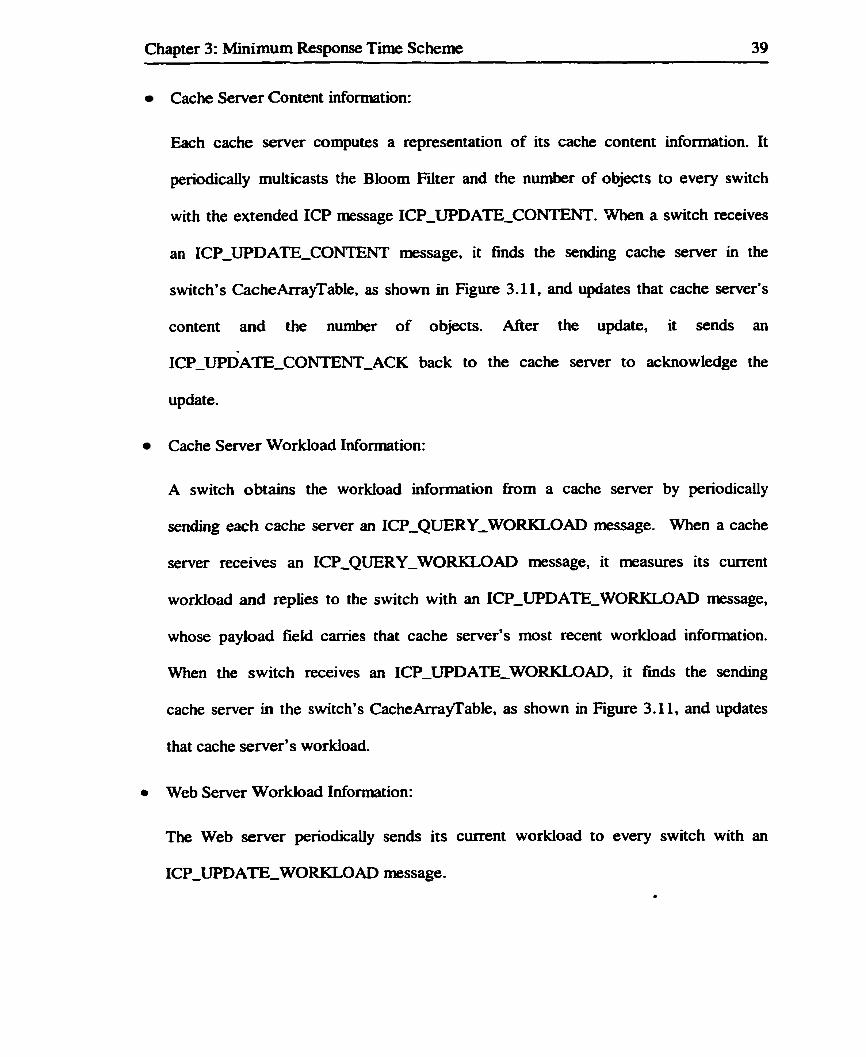
Cache Servet Content infornation:
Each cache server computes a representation of its cache content information. It
periodicaiiy multicasts the Bloom Filter and the number of objects to every switch
with the extended ICP message ICP-UPDATE-CONTEEFT. When a switch receives
an ICP-WDATE-CONTENT message, it nnds the sending cache server in the
switch's CacheArrayTable, as shown in Figwe 3.11, and updates that cache server's
content and the number of objects. After the update, it sends an
ICP~UPDATE~CONTENT~ACK back to the cache server to acknowledge the
update.
Cache Server Workload Information:
A switch obtains the workload uiformation from a cache server by periodically
sending each cache server an ICP-QUERY-WORKLOAD message. When a cache
server receives an ICP-QUERY-WORKLOAD message, it masures its cwent
workload and replies to the switch with an ICP-UPD ATE-WORKLO AD message,
whose payload field carries that cache server's most recent workload information.
When the switc h receives an ICP-UPDATETEWORKLOAD, it h d s the sending
cache server in the switch's CacheArrayTable, as shown in Figure 3.1 1, and updates
that cache server's workload.
0 Web Server Workload Information:
The Web server periodically sends its current workload to every switch with an
1CPJJPDATE-WORKLOA.D message.
Chapter 3: Minimum Response Time Scheme 40
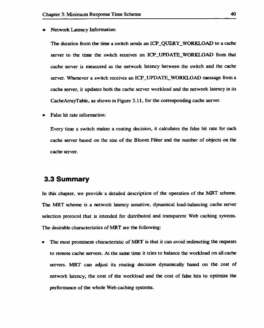
Network Latency Information:
The duration fiom the time a switch sends an ICP-QUERY-WORKLOAD to a cache
server to the t h e the switch receives an ICP-WDATE-WORKLOAD fiom that
cache server is rneasured as the network latency between the switch and the cache
server. Whenever a switch receives an ICPUPDATE-WORKLOAD message fiom a
cache server, it updates both the cache server workload and the network latency in its
CacheArrayTable, as shown in Figure 3.1 1, for the corresponding cache server.
False hit rate information:
Every tùne a switch rnakes a routing decision, it calculates the false hit rate for each
cache semer based on the size of the Bloorn Filter and the number of objects on the
cache server.
3.3 Summary
In this chapter, we provide a detaiied description of the operation of the MRT scherne.
The MFtT scherne is a network latency sensitive, dynaniical load-balancing cache server
selection protocol that is intended for distributed and transparent Web caching systems.
The desirable characteristics of MRT are the following:
The most prominent charactenstic of MRT is that it can avoid redirecting the requests
to remote cache servers. At the same tirne it tries to balance the workload on all cache
servers. MRT can adjust its routing decision dynamically based on the cost of
network latency, the cost of the workload and the cost of false hits to optimize the
performance of the whole Web caching systems.

Chapter 3: Minimum Response Time Scheme 41
MRT is completely distn'buted. In such a M y distributed architecture a single point
of failure can be avoided and the cache sharing cm be achieved by ailowing more
clients to share multiple cache servers.
The MRT server selection algorithm is done by a Layer 5 switch compared to other
server selection algorithms that are done by the client or cache servers. Layer 5
switches can perform the routing very efficiently.
MRT extends ICP protocols and is compatible with existing Web caching systems.
The extended ICP messages aUow the switch and cache server in the MRT scheme to
cooperate with switches and cache servers that do not support MRT.

Chapter 4: Performance Evaluation 42
Chapter 4
Performance Evaluation
In this chapter, the performance of the MRT scheme is studied. The results are analyzed
and compared with the Content, Workload, R'IT and LB-LS schemes. We chose those
schemes for comparison because they represent the range of cache sever selection
algonthms used in distributed switching-based transparent Web caching systems. Section
4.1 describes the simulation model, which includes the network rnodel, the network
latency model, the workload model, the invalidation-checking model and the simulation
parameter settings. Section 4.2 describes how the Content, Workload, RTT and LB-LS
schemes work in our simulation. Section 4.3 presents the performance metrics that we
use to represent the performance of the different schemes. The effects of the network
latency, request intensity, expiration tirne and the nurnber of cooperating cache servers on
the performance of the MRT are investigated and the results are reported in Section 4.4.
Finaiiy, a su- of this chapter is provided in section 4.5.

Chapter 4: Performance Evaluation 43
4.1 Simulation Model
To evaluate the MRT scheme and to compare it with other schernes, we constnict a
simulator that ailows us to observe and masure the performance of the schemes under
different network latencies, different HTTP request intensities, dBerent values of object
expiration time and different number of cache servers. The simulator consists of a
network model, a network latency model, a server workload model and a cache semer
content validation checking model.
4.1.1 Network Model
The network model for each of the five Web caching schemes sirnulates a M y
distributed switching-based Web caching system, as s h o w in Figure 4.1. A client cluster
connects to its own Layer 5 switch. which connects to all the cache servers and the Web
server. A cache server connects to al1 the switches and the Web server. There are no
direct connections between cache servers and there is no direct connection between a
client cluster and a cache server. The cache sharing is achieved through the Layer 5
switches.

Chapter 4: Performance Evaluation 44
Client Clusta Client Clustcr
Figure 4.1 Network Model
4.1.2 Network Latency Model
It is difficult to mesure the network latency in a simulation. M. Rabinovich et a1 1381 use
a distance metric to reflect the costs of transfeming data between any two nodes. The cost
may include monetary costs, tirne, bandwidth of the connection, etc. The cost of
transfexring data between two nodes is proportional to the distance between that pair of
nodes. We adopt a similar method in our simulation. Our network latency mode1 is based
on a symmetric architecture with n client clusters, n switches and n cache servers, as
shown in Figure 4.2. In our simulation, n varies from 2 to 8.

Chapter 4: Performance Evaluation 45
Network Latency (switch Network Latency
Netwrk Latency (client i, s~ i t ch i)
. Web Server)
Figure 4.2 Network Latenc y Mode1
We calculate the network latency between node i and node j, which is the cost of
transfening data between them as follows:
Distance (i, j) = li-JI (4- 1)
NetworRLatency (i , j) = Distance (i. j) * LatenryFactor (4-2)
NetworkLatency (i.j):The time spent on the network when data are transferred from
node i to node j, which is measured in diiseconds.
LutencyFactor: The time spent on the network when data are transferred for one unit
of distance. It is measured in milliseconds.
In order to investigate the effect of the network latency between the cache servers and the
switches on the performance of aii the schemes, we vary the LatencyFactor fkom 5
milliseconcis to 125 miiliseconds in o w simulation and the results are studied in Section

Chapter 4: Performance Evaiuation 46
4.1.3 Workload Model
The researc h coxnmunity has made progress tow ards characterizing workload patterns for
Web sewers and proxy cache servers using Benchmarks, such as those by Almeida and
Cao 1391 and Barford and Crovella 1401. Proxy traces can also provide an alternative
rneans of workioad generation that is able to account for client access patterns and the
requested content 121.
We use publicly available proxy traces fiom the NLANR to generate Hï"iT requests [2].
In our simulation we use the July 26, 2001 and August 27, 2001 traces fkom the NLANR
Boulder cache servers. Client IP addresses are randomized daily and are consistent within
a trace but not between traces. Each trace spans 24 hours and contains from 100,000 to
400,000 total requests. Each entry in the trace has 9 fields. In our simulation the
TimeStamp, ClientAddress, Size and URL fields are used. They are defined as follows:
Timestamp: specifies the time when the client generates the HTTP request. The
format is 'Unix time" with miIlisecond resolution
Client Address: The IP address of the client cluster
Size: The numkr of bytes transferred fiom the proxy to the client
URL: The uniform resource locator, which is a character string describing the
location and access method of a resowce on the Internet.
In raw proxy traces HTTP requests are generated at the time specified by the TirneStarnp
field. The controlIed proxy traces Vary the request inter arriva1 times to simulate the
different JXïTP request intensities. For example, if in the raw trace the average number of
HïTP requests generated by the client clusters is 2000 per 10 minutes, the average inter

Chapter 4: Performance Evaluation 47
arriva1 time is: (10*60*1000) 1 2000 niillisecon&. In controiied proxy traces. for a 50%
request intensity, we can enlarge the average interval by 2 and for a 200% request
intensity. we can shorten the average interval by 2.
We masure the average workioad of a server (cache server or the Web server) in our
simulation as folio ws :
Average Num of TCP connections Per Second Average Workload=
Maximum Num of TCP connections of the Server Per Second (4.3)
The average nurnber of TCP connections is calculated as foliows:
AvgTCPNum = (1- Wq) * AvgTCPNum + W,*TCPNum (4-4)
AvgTCPNum: The average nwnber of TCP connections per second.
TCPNum: The active number of TCP connections.
Wq: A weight factor, O < Wq < 1.
If Wq is too large, then the averaging procedure may not filter out transient congestion or
busty traffic. If Wq is too low, then the average number of TCP connections responds too
slowly to changes in the actual number of TCP connections. Many researchers use 0.002
as the value for W, (411. We ran in our simulation with W, as 0.001, 0.002 and 0.25 and
found that Wq = 0.002 is a reasonable choice. The average number of TCP connections in
ow simulation is therefore calculated as:
AvgTCPNum = 0.998 * AvgTCPNum + O.OOS*TCPNum
4.1.4 Validation Checking Model
Cache servers sometimes provide users with stale pages, which are out of date with
respect to the copies on the Web servers. If a page is stale then the HTTP request is

Chapter 4: Performance Evaluation 48 --
redirected to the original Web semer for the refieshed object. In order to reduce the time
wasted on stale pages, a cache server must validate the pages in its cache so that it cm
give refresh pages to users. Al1 known Web caching systems use validation check
mechanisms to maintain cache consistency [2 11431 1441. Some widely used proxy servers,
such as the World Wide Web Consortium's httpd (formerly CERN httpd) [43] and
Netscape's Roxy Semer 1441 - use an expiration mechanism to keep their pages up to
date.
The expiration mechanism works as foilows. Each cached page is assigned an expiration
the . Any GET requests made before the expiration tirne elapses are answered with the
cached page. M e r the expiration time elapses, the cache server directs the GET request
to the Web server. After receiving the Web semer's response, the cache server resets the
page's expiration time to its default value. The detailed pseudo code for W3C httpd 3.0
cache consistency c m be found in Appendix C.
Expiration-based caches use a variety of mechanisms to assign expiration t h e s for
cached pages. The field "Expires: date" in the H T ï P request header, rneans that the
document definitely will not change before the given date and probably will change soon
after the given date. The Web server may retum such a header with a document. It can be
used directly as an expiration t h for cached copies of the document. However, as
Glassman [45] points out, the header Expires: date is rarely used. This is not surprisîng,
since the author of a WWW page usualiy can't estimate a document's lifetime at the time
it is created.

Chapter 4: Performance Evaluation 49
For documents with no Expires: date header. the simplest expiration time algorithm used
by the cache server is to assign each object an expiration time equal to be '/4 to !4 of the
average lifetinie of that object [Ml. The average Metirne of an object is an average
intervat between two successive modifications of the same URL. The average Metune of
an object is affected by the type of the object, such as HTML, GIF or AUDIO. It is also
affected by the class to which the object belongs, such as the COM class, the EDU class
or the NEWS class (The average Metirne in NEWS classes usually is 1 -2 days). We
assume that all objects studied in our simulation belong to the NEWS classes. We varied
the expiration time fiom 3 hows to 24 hours to investigate the effect of difFerent
expiration times on the performance of the investigated Web caching schemes.
The irnplementation of the simulation software is based on the simulator used by 2.
Liang [20]. We add the validation checking mechanism io the proxy cache server. The
Web server supports ICP messages. We implement the layer 5 switches used in the
Content, Workload, RTT and MRT schemes. The detailed software structure of the
simulator is described in Appendix D.
4.1.6 Simulation Parameter Setting
The parameter settings used in the simulations are simiiar to the values used by Z. Liang
1201. The parameters are summarized in the foiiowing tables:

Chapter 4: Perforxnance Evaiuation 50
Meaning The round trip t imz between a Web client and a LS switch
The round uip time between a Web client and a Cache semer
The round m p time between a LS switch and a Cache server
The round trip time betwcen a LS switch and Web sesver The round trip time between a Cache server and Web semer
Value (rnilliseconds) 130 130 0-400 300 300
TABLE 4.1 PARWEEFtS FOR LINK
Name Value (milliseconds) 1OOO 1OOO O
Meaning
Query\KOrkload-~nterval ECHOJnterval TCES plicing
Routing C heckCac heable
TABLE 4.2 P-S FOR S ~ H E S
The intervai between the QueryWakioad mgs The interval between the ~ c h o msgs The cime it taices a L5 switch port controUer to translate TCP sequence nurnber The tirne it takes a L Sswitch to make a routing decision
The time it takes a LS switch to check the requested object is cacheable or not
Meaning
The time at a Web server between receivinp; a request and reniniinp; the first byte of the requested obi-
- The time it takes a Web server to send an object in memory to the requesting party The interval to send the updared workload
TABLE 4.3 PARAI~~IEIERS FOR WEB SERVER
Value (milliseconds)
150
150
60* 1000
I 1
TABLE 4.4 P-S FOR CACHE SERVERS
Name PC-cac heS ize PC-Seiuch
PC-SearchDigest
PC-D~S~ACC~SS
Pc-Reply
PC-Relay
Pc-C~C heDigest-s ize PC-CacheDigest-Interval
Obimts expkAonTime
Meaning The physical size of a Cache semer
The time it takes a Cache semer CO search for an object in its cache The time it cakes a Cache to search for an object in its cache dip;ests The time it takes a Cache semer to retrieve a cached object from disk to memory The time it takes a Cache server to send an object in rnemory to the requestinn party The time it takes Cache semer to relay a response to the requesting party The si= of a Bloorn Filter for a Cache server
me internai bewen -cutive content-update msgs The time far an object to expire
Value 1024* 1024*64(bytes) 250(mfiseconds)
l()O(milliseçonds)
100(mifiseconds)
150(msecon&)
50(mifise~ond~)
32* 1024 (bytes) 1 *60* lOûû(miUiseconds)
(3-24)*60*60* Io00

Chapter 4: Performance Evaluation 51
4.2 Content, Workload, RTT and LB-L5 Schemes
The Content scheme, Workioad scheme, RTT Scheme and LB-LS Scheme in our
simulation represent certain classes of cache server selection algorithm that are
introduced in chapter 2. The schemes are simulated as follows.
4.2.1 The Content Scheme
The Content scheme represents a class of cache server selection algont h m that redirect
HITP requests oniy based on content. When a Layer 5 switch in the Content schenu:
receives a HTTP request, it makes the routing decision as follows:
(1) If the request is non cacheable, the switch imrnediately redirects it to the Web server.
(2) If the request is cacheable then the switch checks the content of each cache server.
(2.1) If a set of the cache servers is predicted to store the object, the switch randomly
picks one cache server fiom these cache servers.
(2.2) If none of the cache servers is predicted to store the object, the switch picks the
cache server in a round robin rnanner.
4.2.2 The Workload Scheme
The Workload scheme represents a class of cache server selection algorithms that
redirects HTTP requests based on both content and workload of the cache server. When
a Layer 5 switch in the Workload scheme receives a HTTP request. it makes the routing
decision as foliows:
(1) If the request is non-cacheable, the switch innnediately redirects it to the Web server.
(2) If the request is cacheable then the switch checks the content of each cache server.

Chapter 4: Performance Evaluation 52
(2.1) If a set of the cache servers is predicted to store the object, the switch picks the
cache server with the minimum workload arnong these cache servers.
(2.2) If none of the cache servers is predicted to store the object, the switch picks the
cache server with the minimum workload among ail the cache servers.
4.2.3 The R I T Scheme
The RTT scheme represents a class of cache server selection algorithms that redirects
H T ï P requests based on both content and network latency. When a Layer 5 switch in the
RTT scheme receives a HTTP request, it makes the routing decision as follows:
(1) If the request is non-cacheable, the switch immediately redirects it to the Web server.
(2) If the request is cacheable then the switch checks the content of each cache server.
(2.1) If a set of the cache servers is predicted to store the object, the switch picks the
cache server with the smaliest response time among these cache servers.
(2.2) If none of the cache servers store the object. the switch picks the cache server
with the minimum response time to the switch among al1 cache servers.
4.2.4 The LB-L5 Scheme
The LB-5 scheme represents a class of cache server selection algonthms that redirects
HTT'P requests based on the content, the cache server workload and the network latency.
When a Layer 5 switch in the LB-LS scheme receives a H'ITP request, it makes the
routing decision as fol10 ws:
(1) If the request is non cacheable, the switch immediately redirects it to the Web server.
(2) If the request is cacheable then the switch checks the content of each cache server.

Chapter 4: Performance Evaluation 53
(2.1) If a cache server potentially stores the object and the network latency from the
cache server to the switch is not greater than some threshold, then the switch
picks the cache server with minimum workload from these cache servers that
satisfy the above conditions.
(2.2) If al1 the cache servers potentiaiiy store the object have the network latency to
the switch greater than the threshold, then the switch picks its local cache server
regardless whether that cache server has the requested object o r not.
(2.3) If none of the cache servers store the object, the switch picks the cache server
with the minimum workload fiorn those cache severs whose network latency to
the switch is not greater than the threshold.
4.3 Performance Metrics
The following two key performance mtrics are evaluated:
1. Client Request Response Time
The duration from the time a client sen& a TCP connection request to the tirne the
client receives the TCP connection finished signal. It is affected by the workload of
the cache servers and the Web server, the network latency and false prediction. The
client's perception of Web performance is based on the response time. The smaller
the average response time, the be tter the penormance.
2. Average Cache Server Workload
A cache server may be shared by hundreds or thousands of users. At any given
tirne, there are a number of concurrent H l T P requests to the cache server. Object
retrievai times on the cache server Vary with load, and consequently the request

Chapter 4: Performance Evaluation 54 -
response thne varies as well. We define the Ioad on the cache server as the average
number of TCP co~ections per second divided by the maximum number of TCP
connections per second that each cache server can service. The average workload
can be used to indicate the relative balance among the cluster of cache servers.
The average response time indicates the quality of the schews. The efficiency of any
Web caching scherne can be measured in terms of how the workload is balanced across
the cache servers. A balanced workload usudy means lower response times, but
sometimes the two performance rnetrics confiict. For example, to achieve workload
balance a request has to be redirected to a remote cache server at the expense of higher
response times. The ultimate goal of a Web caching system remains to Mnunize response
times.
4.4 Simulation Results
In this section we describe bo th raw-trace driven and controued- trace simulation
experiments. For the raw-trace driven simulatiow, the IFTTP requests are generated at the
time specified by the tirnestamp field in the trace nle. In the controlled-trace simulations,
the HTTP requests are generated periodically and the request inter arrival time is
controiied in order to vary the H'ITP request intensity. AU experiments are done with a
30-minute wann-up period to fill cache servers with objects until all cache servers are full
and the simulated Web caching system is stable. A statistical analysis of the experiments
results reveals that the performance is quite stable. The experiments were run with a 90%
confidence level with 5% confidence intervals.

Chapter 4: Performance Evaluation
4.4.1 Raw-trace Driven Simulations
We ran e x p e h n t s with two raw traces kom proxy servers using NLANR traces [2]. In
order to simulate the cache cooperation arnong different network domains we Mt four
different network domains for four different ciient cfusters based on client IP addresses.
Each trace is for a 24 hours period. We compare the response times of MRT to the other
schernes under different network latencies and HTTP request intensities during one day.
When the network latency is low the workload of cache servers is the main factor
affecting the response tirne. When the workload of the cache server is light, the network
Iatency becomes the main factor affecting the response tirne. The workload of a cache
server is d e t e n - e d by the number of HTïP requests generated by client clusters. Figure
4.3 plots the IFLTP request intensity over one day versus the nurnber of HTTP requests
inl0-minute periods. The request intensity is relatively high kom 8 am to 4 prn The peak
intensity is 2950 requests per 10 minutes around 11 am, and signiticantly decreases after
5 pm. The minimum intensity is 950 requests per 10 minutes around 8 pm.
- -
Figure 4.3 H'iTP Request Intensity

Chapter 4: Performance Evaluation 56 - - --- - -
The response times over one day under different network latencies are shown in Figures
4.4-4.6 below. The simulation results show that MRT outperfonns the other f o u . schemes
and has a better adaptability to high IirrrP request intensities and large network latencies.
When the network latency is very s d , the response times of five schemes foilow the
H ï T P request intensity, as shown in Figure 4.4. The Workload scheme, LB-LS scheme
and MRT scheme consider the workload at the cache servers so they have better
performance than the Content and the R ï T schemes when the request intensity is high.
In Figure 4.4, under a peak request intensity (1050 am), MRT outperforms Content by
22% and RTï by 25%. MRT has siniilar performance to the Workload and LB-LS
schemes.
Under a higher network latency (Latency Factor = 75 ms) as shown in Figure 4.5, the
average response time of MRT is much better than that of Content, Workload R n and
LB-LS. It outperforms Content by 27%, Workload by 17%, R ï T by 20% and LB-LS by
13%. As the network latency increases, the corresponding increase in the average
response times of Content, Workload and LB-L5 schemes is higher than that of RTT and
MRT since the latter schemes respond better to high network latency factor.
When the network latency is very large (Latency Factor = 125ms) as shown in Figure 4.6,
both LB-L5 and MRT avoid redirecting requests to remote cache servers. LB-L5 does
not redirect the requests to cache servers whose network latency to the switch is larger
than the predefined t hreshold (100 milliseconds in our simulation). MRT alwa ys d i r e c t s
the requests to the cache server with the minimum estimated request response thm. MRT

Chapter 4: Performance Evaluation 57
outperforms LB-L5 by ll%, while it outperforms Content by 44% and Workload by
34% since neither of them considers network latency when they make the routing
decision. The average response tirne of RIT does not increase as much as that of Content
or Workload. However, when aii the cache servers that may store the requested object
have large network latency, RTT has to redirect the request to one of them. The average
response time of RTT increases as the network latency increases. MRT outperfom RTI'
ResponseTime (Latency Factoemr)
Figure 4.4 Response Time At Latency Factor = S m

Chapter 4: Performance Evaluation 58
Response T i m (Lstmcy Factor = 75ms)
6 7 8 9 10 11 12 13 14 15 16 17 18 19 20 21 22 23 24
Time
-Content - - - WoMoad - - - - RTT - L B - L S -MRT
Figure 4.5 Response Time At Latency Factor = 75113s

Chapter 4: Performance Evaluation 59
Figure 4.6 Response Time At Latency Factor = 125 ms

Chapter 4: Performance Evaluation 60
4.4.2 Controlled-Trace With Balanced Requests
In this section, we present experiments using controlled traces. We investigate the effect
of the H 3 V request intensity, the network latency and object expiration tim on the
response tirne of MRT. The results are compared with the performance of the Content.
Workload, RTT and LB-L5 schernes. AU experiments are done under the condition that
each client cluster sends the same amount of http requests per 10-minute period. We run
the simulator 8 to 24 hours and sample the request response time every 10 minutes and
present the average of the values with a 90% confidence level.
4.4.2.1 E f k t of Http Request Intensity
Figure 4.7 plots the response tirne versus H T ï P request intensity under Merent network
latency factors. As shown in Figure 4.7, we can see that MRT always outperfom the
ot her SC hernes under different request intensities and network latency factors. The
average HTTP request response time of al1 investigated schemes increases as the HITP
request intensity increases for al network latency factors. This is because the workload of
each cache server increases as the H T P intensity increases. The processing t h e of
cache servers increases too. The extent of the increase on response time for each scheme
is different.
The Content and RTT schems are greatly affected by the IFITP request intensity since
neither of them uses the workload information about cache servers when they make the
routing decision. Content selects the cache server that is picked randomly or in a round
robin fashion. RTï selects the cache server that stores the object and has the minimum

Chapter 4: Performance Evaluation 61
network latency to the switch. They may cause unbalanced load distriiution on those
cache servers, although originaliy client-clusters have balanced requests. The imbalance
is more obvious when the H ï T P request intensity increases.
The Workload, LB-L5 and MRT schemes adapt better to high request intensities because
they are aware of the workload of al1 cache m e r s . These schemes always try to direct
requests to lightly loaded cache servers. The request response times of Workload, LB-L5
and MRT are less than that of Content and RTT, since the processing time on a lightly
loaded cache server is less than that on a heavily loaded cache server. The irnprovement
on response tirne is more apparent when the request intensity increases, as shown in
Figure 4.7. The average increase of response time is amund 1400 millisecond for both
Content and RTï when the H T P request intensity increases fiom M I to 2502, while
the average increase of response time is only around 700 milliseconcis for Workload,
LB-L5 and MRT.
We also see that the performance advantage of MRT is more obvious as the network
latency factor increases. For example, in Figure 4.7 (a) with 50% H T T P request intensity
and 5 dseconds network latency factor, MRT perEorms similady to the Content,
Workioad and R n schemes. On the other hand, when the network latency factor is 125
milliseconds, as shown in Figure 4.7 (f), MRT outperforms Content, Workload and RIT
by 52%, 51% and 2 8 4 , respectively. For LE3-LS the situation is a Little different. When
the network latency factor is greater than 100 milliseconcis, a switch redirects the H T W
requests to its local cache server. The average response time of LB-L.5 does not increase

Chapter 4: Performance Evaluation 62 - -- - -
when the network latency factor is greater than 100 milliseconcis. The average response
thne of MRT increases slowly as the network latency factor increases. As show in
Figure 4.7 (a) to (0, under 50% H ï T P request intensity, when the network latency factor
is 30, 50, 75, 100. 125 milliseconds, MRT outperforms LB-L5 by 7%. 15.51, 20%,
21.2% and 19.2%, respectively.

Chapter 4: Performance Evaluation 63
Figure 4.7 Average Response Time Versus H ï T P Request Intensity

Chapter 4: Performance Evaluation 64
4.4.2.2 Effect of Network Latency
Figure 4.8 illustrates the average response time versus network Iatenc y factor. The
experiments are conducted under different H l T P request intensities. MRT outperforms
the other schemes for all values of network latency and for each H T ï P request intensity.
Basicaily, the average request response time for ail investigated schemes increases as the
network latency factor increases under different request intensities. However, the
extent of the response tirne increase for each scheme is different.
The Content and Workload schernes are highly afEected by the network latency shce
both of them do not consider the network latency when they make the selection decision.
As we know, in the Content scheme, the cache server for a request is picked randomly or
in a round robin fashion. In the Workload scheme, the selected cache server is the one
that has the minimum workload. In both cases, if the network latency ftom the selected
cache server to the switch is large, then there can be a noticeable increase in the average
response time. As shown Figure 4.8, the average response time of Content and Workload
respectively increases by 20% and 30% as the network latency factor increases h m 5 to
125 rnilliseconds with 250% H I T P request intensity. The increase is more apparent when
the H ï î T request intensity is small. The average response time of Content and Workioad
respectively increases by 62% and 64% as the network latency factor increases from 5 to
125 milliseconcis with 50% HïTP request intensity.
The R I T scheme knows the up-to-date network latency. It tries to redirect the requests to
the cache server with minimum network latency, so the arnount of increase in the average
response time is smaller than in the Workload and the Content schemes. We found,

Chapter 4: Performance Evaluation 65
however, the average response time of RTT is highly affected by the network latency
factor. If the cache servers that potentially store the requested object have huge network
latency to the switch, the average response time increases as the network latency
increases. As shown in Figure 4.8 the average response time of RTT increases by 40%
and 14% as the network latency factor increases fiom 5 to 125 milliseconcis for 50% and
250% H T ï P request intensities, respectively.
For LB-L5, when the network Iatency factor is smaü, the selected cache server is the one
that has the minimum workload among the servers storing the requested object. It is
similar to the Workioad scheme under small network latency, and the average response
time highly depends on the network latency. In Figure 4.8 (a) we can see that the average
response time increases around 30% when the network latency factor increases firom 5 to
100 milliseconds. However, if the network latency factor is very large, the switch does
not redirect requests to rernote cache servers. Instead, it redirects the requests to the local
cache servers no matter if it stores the requested object or not and no matter if it has the
minimum workload or not. The average response thne remains the same when the
network latency factor increases fwther.
MRT knows the most recent information about the network latency and server workload.
Using this information, MRT can predict the request response time and automatically
adjusts the cost incurred by the workload and network latency. It chooses the server that
can service the request fastest. As shown in Figure 4.8, we can see that the response tirne
increases modest with the increase of network latency. The increase in the response time

Chapter 4: Performance Evduation 66
is only about 11% and 7% as the network Iatency factor increases tiom 5 to 125
milliseconcis for 50% and 250% H I ï F request intensity, respectively.
MRT has a better performance when the Web caching system has high request intensity
o r large network latency. When the request intensity is 50% and the network latency
factor is 5 milliseconds the average response time of MRT is similar to the Content,
Workload, R n and LB-L5 schemes. However, when the request intensity is 250% and
the network latency factor is 125 milliseconds, the average response tirne of MRT is
lower than that of Content, Workload, RTT and LB-LS by 70%, 34% 49% and 9%,
respec tively.

Chapter 4: Performance Evaluation
Figure 4.8 Average Response Time Versus Network Latency Factor

Chapter 4: Performance Evaluation 68
4.4.2.3 Effeet of Object Expiration T i
The expiration time is the period during which the obNt is assumed valid in a cache
server. If an object is out of date, it has to be retneved fkom the original Web server. This
can result in a huge increase in the request response time. Proxy cache semers in our
simulation use the expiration tirne mechanism to do validation checking. In this way, the
object need only be retrieved once from the original Web server within its expiration
Figure 4.9 iilustrates the response t h e versus object expiration tirrie. The experiments are
done under 100% HTW request intensity. The shorter the expiration tirne, the more often
validation checking is perfomd. As shown in Figure 4.9, the average request response
times of all investigated schemes increase as the object expiration time decreases. In
Figure 4.9 (a), for a small latency factor (Sm), when the object expiration tirne decreases
fiom 24 hours to 3 hours, the average response times of Content, Workload, RTT, LBLS
and MRT increase by 13.5%, 14%, 1 1.596, 14% and 12%, respectively. In Figure 4.9 (b),
for a larger latency factor (75ms), when the object expiration tirne decreases from 24
hours to 3 hours, the average response time of Content, Workload, R n , LB-L5 and
MRT increases by 12%, 19%, 8%, 16% and IO%, respectively. It should be noted that the
relative increase in average response time for al schernes is not significantly affecteci by
the latency factor.

Chapter 4: Performance Evaluation 69
Figure 4.9 Average Response Time versus Expiration Time
4.4.3 Controlled-Trace With Unbalanced Requests
In this section, we present experiments using controlled traces with unbalanced client
request intensities. We investigate the effect of unbalanced workload and the network
latency on the average response tirne of MRT. The results are compared with the
performance of the Content, Workload, RTï and LBLS schernes. The experiments are
conducted for 4 client clusters where client clusters 1 and 3 have 50% HTTP request
intensity, while client clusters 2 and 4 havel50% HTTP request intensity. We run the
simulator 8 to 24 hours and sample the request response t h every 10 minutes.
Figure 4.1 O (a. 1) to (e. 1) plot the average workload of the four tested cache servers under
different network latency factors for each scheme. Figure 4.10 (a.2) to (e.2) plot the
average request response tirne versus the network latency factor for each scheme. The
Content scheme selects the cache server in a round robin fashion. It may balance the

Chapter 4: Performance Evaluation 70
workload on all cache servers, as shown in Figure 4.10 (al). The Workload schemz
balances the workload of the four cache semers for ail network latency factors. Workload
moves some load fkom the heavily loaded cache servers to the lightly loaded cache
servers so that the workload on all cache servers is balanced, as shown in Figure 4.10
(b.1). This reduces the processing time on the heavily loaded cache servers. When the
network latency is low, the communication cost to other cache servers is low and the
balanced workload on the cache serven can reduce the average response tirne. For
example, in Figure 4.10 (b.2) the average response time is only 1146 milliseconcis when
the network latency factor is 5 milliseconds. When the network latency factor increases,
the communication cost to the rernote cache servers increases, so the benefit from the
balanced workload on each cache server cannot compensate for the communication cost.
The average response tirne increases rapidly as the network latency increases. The
average response thne increases up to 1724 milliseconds when the network latency factor
is 1 25 milliseconcis.
The RTT scherne cannot balance the workload of the four cache servers since it does not
use the cache servers' workload information and always redirects the request to the cache
server that may store the object and has the minimum network latency. In Figure 4.10
(c. 1) we observe that cache servers 2 and 4 are heavily loaded for ail network latency
factors. The queuing tirne on these two cache servers is very large, which means that the
average response time is large. Figure 10 (c.2) shows the average response time is 1373
milliseconds when the network latency factor is 5 rnili.iseconds, which is 17% more than
that of Workload scheme. The average response tirne of R n increases slower than that

Chapter 4: Performance Evaluation 71
of Workload as the network latency factor increases, since it mainly depends on the
network latency. The average response time is 1700 milliseconcis when the network
latency factor is 125 milliseconcis, which is almost the same as the Workioad scheme.
The LFl-LS scherne balances the workload of cache serves under small network latency
factors. Figure 4.10 (d.2) shows the average response time is only 1146 IIiilliseconds
when the network latency factor is 5 milliseconcis. When the network latency is p a t e r
than 100 mïUiseconds (the LB-I.5 threshold), LB-L5 redirects the request only to its own
cache server, so the cache server sharing capability and load balancing capabüity are lost.
The average response time is 1339 rniiliseconds when the network latency factor is 125
milliseconds, which is 17% higher than that at a network latency factor of 5 milliseconcis.
The MRT scherne balances the workload of cache servers for srnall network Iatency. The
balancing capabilit y decreases, as the network latenc y increases. MRT calculates the
queuing cost and the communication cost. In Figure 4.10 (e.1) we see that MRT's
workload balancing capability is better than that of LB-L5 under large network latency.
The rate of the unbalanced workioad of LBLS on cache server 3 and 4 reaches 300%,
while that of MRT on cache server 3 and 4 is only about 100%. In Figure 4.10 (e.2) we
can see the MRT's rate of increase of average response t h e is slower than that of LB-L5
and RTT. Although the workload balancing capability of MRT is not better than
Workload or Content, the average response time of MRT is much better than that of the
Workload and Content schemes.

Chapter 4: Performance Evaluation

Chapter 4: Performance Evaluation 73
MRT Schame
- -
(e* 1) (e-2)
Figure 4.10 Workload and Average Response Time
4.4.4 Effect of Number of Cache Server
This section presents experiments under different number of cooperating cache servers
for different IFITP request intensities and network latency factors. To provide a fair
cornparison when we change the number of coopering cache servers, we fix the total
number of H'ITP requests generated by client clusters and the total capacity of the W e b
caching system. We expect that, if the number of cooperating cache servers is small, then

Chapter 4: Performance Evaluation 74
the number of HTTP requests that each cache server services wili be large and the
communication cost between cache servers will be smail. SimilarIy, if the number of
c o o p e ~ g cache servers is larger, then the number of HTTP requests that each cache
server services will be small and the communication cost between cache semers wili be
large.
Figure 4.11 plots the response time versus the nurnber of cooperating cache servers.
Figure 4.1 1 (a) and (b) show the impact of the number of cache severs for 100% H T ï P
request intensity. As the number of cooperating cache servers increases, the number of
HTTP requests on each cache server decreases and the processing tirne on each cache
server decreases. When the network latency factor is very smaii (5 milliseconds), the
communication cost between cache servers can be ignored. The average response time is
mainly determined by cache servers processing tirne. The average responses time of ail
schemes decrease as the number of cache servers increases.
When the network latency factor is large (50 milliseconcis), the communication cost
between cache servers cannot be ignored. As the number of cooperating cache servers
increases, the communication cost also increases. The average response time is
determined by both the communication cost and the cache semer processing time. RïT
tries to mhimize the communication cost when it routes requests. MRT tries to minimize
the sum of the communication tirne and the processing tirne. When the network latency
factor is 50 mïliiseconds, the expense of the communication cost negates the benefit fkom
reducing the processing thne on each cache server. Content, Workload and LB-L5 can
distribute the client requests to more cache servers as the number of cache servers

Chapter 4: Performance Evaluation 75
increases. Therefore, the workioad on each cache server decreases. However,
communication cost increases as the number of cache servers increases. The average
response time of Content, Workload and LBJ5 increases when the number of cache
servers is greater than 4, as shown in Figure 4.1 1 (b). For RTI' and MRT, the average
response time always decreases as the number of cache semers increases.
Figure 4.1 1 (c) and (d) show the results of experiments with 200% HTTP request
intensity. The performance improvement by splitting the workload of cache server is
more significant. In this situation regardless of the network latency (5 or 50
miliiseconds), the average response tirne of ali schemes decreases as the number of cache
servers increases. As expected earlier, the rate of the decrease of the average response
time under a srnail network latency factor is higher than that under a larger network
latency factor. When the network latency factor is s d (5 milliseconds), see Figure 4.11
(c), the average response time of Content, Workload, R'IT, LB-L.5 and MRT decreases
by 45%. 48.6%. 40.4%, 48.6% and 49.5%, respectively as the nurnber of cache servers
increases from 2 to 8. When the network latency factor is large (50 milliseconds), see
Figure 4.11 (d), the average response time of Content, Workload, R n , LB-LS and MRT
decreases by 31.5%, 35%. 32%, 41.4% and 43.5%. respectively as the number of cache
servers increases kom 2 to 8.

Chapter 4: Performance Evaluation 76
Number of C.cW
Figure 4.11 Average Response Time Versus The Number of Cache Servers
Chapter 4: Performance Evaluation 77
4.5 Summary
This chapter presents an evaluation of the performance of the proposed MRT Web
caching scheme, through a comprehensive simulation. The pedormance of MRT is
compared with that of the Content, Workload, R'IT and LB-LS schemes. The network
model, the network latency model, the server workioad model, the validation checking
model and the simulation experimental settings are descriid. Two types of simulation
experiments, namely raw trace and controiled trace were conducted to uivestigate the
effects of the network latency, HTTP request intensity, expiration time and the n u m k of
cooperating proxy servers on the performance of the MRT. The results are compared with
the other transparent distributed Web caching schemes.
The simulation experiments show that MRT outperforms Content, Workload, RTT and
LB-L5 in the term of the kFITP request response tirne. MRT always achieves
significantly lower request response time than that of other schemes, under different
network latencies, H T P request intensities and object expiration time values.
In the raw-trace experiments, MRT oritperforms Content, RTT by an average of 13% and
1296, respectively and has a similar performance as Workload and LB-LS under srnall
network latency. The performance advantage is more prominent when the network
latency is large. MRT outperfom Content, Workload, Response and LB-L5 by 44%.
34%, 30% and 1 1 %, respectively.

Chapter 4: Performance Evaluation 78
In the controlied-trace experiments, it is shown that MRT, like Workload and LB-LS,
adapts better to higher request intensities than the Content and R ï T . For examples. at a
latency factor of 30 milliseconcis, MRT outperforms Content. Workload. RTï and
LB-L5 by an average of 19%. 7%. 14% and 7%, respectively when the HTTP request
intensity is 10046, as opposed to 47%. 7%. 38% and 7%. respectively when the H T W
request intensity is 250%. MRT also adapts better to large network latency. For example
at HTI'P request intensity of 100%. MRT outperforms Content and R'ïT by 1446 and
15.5%. respectively and has similar performance as Workload and LB-LS when the
network latency factor is 5 milliseconcis, as opposed to 35%, 44%, 36% and 12%,
respectively when the network latency factor is 125 milliseconcis. It is ais0 shown that the
average response time Uicrease of MRT is more controlied than that of Content,
Workload and r B L 5 when the expiration time decreases. The experiments conducted
for investigating MRT cache server workload balancing show that the workload of
cooperating cache server are wel balanced when the network latency is srnail. For large
network latencies. MRT balances server workioad better than RTï and LB-L5.

Chapter 5 Conclusion 79
Chapter 5
Conclusion
The objective of this research is to optimize the performance of transparent distributed
Web caching systems in terms of request response tirne. The proposed Minimum
Response Time (MRT) scheme distinguishes non-cacheable requests from cacheable
requests based on HTTP request header. It inteiiigently redirects cacheable requests to the
cache server with the minimum H ï T P request response time. MRT estimates the HTTP
request response time based on cache server content, cache server workload, Web server
workload and network latency. MRT uses four extended ICP messages and one extended
switch routing table to track the most recent update of the above information.
5.1 Contributions
In general, our work has accomplished the following goals:
We studied different switching-based transparent Web caching schemes. We
investigated how they combine to support cache cooperation in distributed Web
caching systems. We also analyzed the advantages and disadvantages of different
server selection algorithms.

Chapter 5 Conclusion 80
W e proposed a heuristic solution to optimize the @ormance of the distributeci L5
switching-based transparent Web caching system, namely the Minimum Response
Time (MRT) scheme. MRT improves upon the performance of other schernes.
A detailed simulation mode1 was developed to study the performance of the proposed
MRT Web caching scheme. We compared the performance of MRT with Content,
Workload, RTT and LB-L5 Web caching schemes. Performance results show that
MRT outperforms all other schernes in terms of HïïF' request response tirne. MRT
outperforms Content, RTT and LES-L5 in terms of workload of cache servers. MRT is
also shown to adapt better not only to high H'ITP request intensity and unbalance
request intensity but also to large network latency.
5.2 Future Work
There are a number of aspects of Our work that need fwther investigation:
Object size: In our research, when we estimate the request response time, we do not
consider the object sue. The object size affects the tirne spent on server delay, which
is incurred retrieving the object from the disk, and the thne spent on the transmission
latency. These times may have a significant effect on the request response time if
most of the requested objects are large objects, such as Video or Audio documents.
Request response tirnes cannot be compared directly if objects are of different size.
How te map the object size to time cornponents remains open for future research.
Huge network latency: The balancing between network latency and server
workloads has an inherent problem. In MRT, when the network latency factor is

Chapter 5 Conclusion 81
huge, al1 client requests are dnected to the Web client's local cache server. The
cooperation among cache servers is lost and the workload of cache servers cannot be
effectively balanced. MRT is suitable to use among a cluster of cache servers within
reasonably large network latency. The cooperation among cache server clusters with
huge network latency need to be investigated further-
Request Priority: The Layer 5 switches used in MRT can distinguish dinerent types
of the requested objects, such as multimedia objects or image objects. Layer 5
switches can assign priorities to requests for different types of objects so that switches
can service high priority requests before low pnonty requests. This kind of prioritized
transparent Web caching should be investigated further.

B ibliograp hy 82
Bibliography
Cl] K. Clam and D. WesseIs, 'TCP and the Squid Web Cache". 1997
[2] National Laboratory for Applied Network Research (NLANR). Ircache project .
Available at htt~://ircache.nlanr.net/.
[3] M-Abrams, C.R. Standridge, G. AWuUa, S.Wiïams, and E.A.Fox. Caching Proies:
Limitations and Potentials. In Proceedings of the 4& Intemutional World-Wide Web
Conference. 1995
[4] A-Bestavros. Speculative Data Dissemination and Service to Reduce Server Load,
Network T r a c , and Service Time for Distributed Information Systems. In
Proceedings of the 1996 Intemational Conference on Data Dissemination. 1996
[SI A. Wolman, GVoeker, N.Sharma, N. Cardweii, A.Karlin, and H. Levy, "On the
scale and performance of cooperative web proxy caching". In Proceedings of the I Th
Symposium on Operating Systems Principles, December 1999.
[6] P. Rodnguez, C. Spanner, and E. biersack, 'Web caching architectures: Hierarchical
and distributed cachingl'. In Proceedings of the dfh International Web Caching
Workshop. April1999.

B ibliograp hy 83 - - - - -
17) C. Jefferey, S.Das, and G. Bernal, "Pioxy Sharhg Proxy Se~ers". In Proceedings of
the IEEE ETA-COM ConJerence, Portland, OR, May 1996.
181 Cieslak, M., and Foster, D. 'Web Cache Coordination Protocol V 1.0". Internet D r 4
of ZETF, drafr-ierf-wec- web-pro-ûû. txt, Jun 1999.
[9] D. Wessels. ''Configuring Hierarchical Squid Caches", 1997
[IO] A. Chantkuthod, P. B. Danzig, C.Neerdaels, M.F. Schwartz and K.J. Worrell. "A
Hierarchical Intemet Object Cache". Tec hnical Report 95-6 1 1 -University of
Southern California, Boulder, California, U.S.A. 1996
[Il] D. Wessels and K. Claffy, 'Intemet Cache Protocol (ICP), versionî". RFC 2186,
Sep 1997
[12] A. Rousskov and D. Wessels, "Cache digests". In Proceedings of the Third
International WWW Caching Workshop, Manchester, England, June 1998.
[13] S. G. Dykes, C.L.Jeffery, and S.Das, 'Taxonomy and design analysis for distributed
web caching". In Proceedings of the ZEEE Hawaii Int'l. Conference Con System
Sciences (HZCSS'99), Jan. 1999
1141 D.Povey and J. Harrison. "A distributed internet cache". In 206 Australian
Computer Science Conference, Feb 1997
[15] R. Tewari, M.Dahl.in, H.M.Vin, and J.S. Kay, 'Design considerations for distniuted
caching on the Internet". In Proceedings of the International Conference on
Distributed Computing Sysîems (ICDS'99), 1999.
[16] R. Malpani, J-Lorch, and D. Berger, "Making World Wide Web caching servers
cooperate". In Proceedings of the Fourth Znternational World Wide Web
Conference, Dec 1995.

[17] B. Wiiliarns, 'Transparent web Caching Solutions", Director of Strategic Business
Planning, Alteon Networks. White Paper. In The third Intemational WWW Caching
Workshop, 1998.
[ 1 81 h o wPoint Communications, "Content Srnart Cache S witching". White paper.
[ 193 ACEdirector 'Zoad Balancing - Technicd S pecifications". Product Overview , 2000
1201 2. Liang, H-Hassanein and P.Martin 'Transparent Distniuted Web Caching". In
Proceedings of the IEEE Local Cornputer Network Conference, Nov 200 1, pp.225-
233.
12 11 Extrerne Networks Server Load Balancing. TechBrief, 2000
[22] Cisco CSS-11150 - Content Services Switch. Cisco Product Catalog, Jan 2002
[23] M.E.Crovella and R.L.Carter, 'Pynamic server selection in the intemet". In
Proceedings Of the Third IEEE Workshop on the Architechue and Implementation
of High PreJCornrn. Subsysterns (HPCS'95), Aug.1995, pp.158-162
[24] J.D.Guyton, M.F.Schwartz. 'Zocating Nearby Copies of Replicated Internet
Services". In SIGC0MMp95, Cambridge, MA, USA, pp.288-298, 1995
[25] R.L. Cater and M.E.Croveila, "Server selection using dynamic path characterization
in wide-area networks". In Proceedings Of ZEEE Infocom '97, Apr. 1997
1261 MaSayal, Y .Breitbart, P.Scheuermann, and R. Vingralek, 'Selection algorithms for
replicated web servers". In Peformance Evaluation Review, vo1.26, no.3, pp.44-50,
Dec. 1998.
[27] S.G.Dykes, Ka. Robbins and C.L.Jeffery, "An Empirical Evaluation of Client-side
Server Selection Algorithrns". In Proceedings Of ZEEE Infocom'OO, Vol 3,
pp. 136 1 - 1370, Mar, 2000
Bibliography 85
[28] D. Andresen, T.Yang, V-HoImedahl, and O,H.Ibarra, "SWEB: Towards a scalable
World Wide Web semer on multicomputers". In Proceedings Of the I @ Znt'l,
Parallel Processing Synrp. (ZPPS'96), Apr 19%.
1291 D. MSias, W-Kish, R.Mukherjee, and R.Tewari, "A scalable and highly available
web server". In Proceedings Of the 41st lEEE Computer Society Int'l, Conference,
Feb. 19%.
[30] Internet Control Message Protocol; RFC 792, Sep 1981
1311 G. Apostolopoulos, V. Peris, P.Pradhan, and D.Saha, '25: A self leaming Layer 5
switch". Technical Report RC2 1461, IBM, T.J. Watson Research Center, 1999
[32] Hypertext Transfer Protocol -- HlTP/l. 1. RFC 2068, Jan 1997
[33] SSH ProtocoL Znternet Draft of R F , drufi-ietf-secsh-connect-14. M. Nov 200 1
[34] C-Yoshikawa, B.Chun, P.Eastham, A.Vahdat, T. Anderson, and D.Culler, 'Vsing
srnart clients to build scalable services". In Proceedings Of the 1997 USENIX
Annual Technical Conference (USENIX'97), 1997, pp. LOS- 1 17
[35] L.Fan, P.Cao, J. Almeida, and AZBroder," Surnmary cache: A scdable wide-area
web cache sharing protocoi". Technique Report, pp.1461, Department of Computer
Science, University of Wisconsin-Madison, Feb 1998.
1361 C. Faloutsos and S. Christodoulakis, 'Design of a Signature File Method that
Accounts for Non-Uniform Occurrence and Query Frequencies". In Proceedings of
II" Znrentaîional Conference on VLDB, pp. 165- 170, Stockholm, S weden, August
1985.
[373 A. Rousskov and V.Soloviev, "On performance of caching Proxies". In Proceedings
of the Joint International Conference on Measurement and Modeling of Cornputer

B ibliograp hy 86
Systems (SZGM~CS'9WERFORUANCE '98), pp. 272-273, Madison, Wl, June
1998
[38] M. Rabinovich, J. Chase, S. Gadde, "Not AU Hits Are Created Equal: Cooperative
Roxy Caching Over a Wide-Area Network". In Computer Networks And ZSDN
Systems, 30,22-23, pp.2253-2259, Nov 1998
[39] J. Almeida and P.Cao, "Measuring Roxy Performance with the Wisconsin Prxoy
Benchmark*'. In Proceedings of the mird Inremutional Caching Workshop, June
1998
[40] P. Barford and M. Crovella, "Generating Representative Wb Workloads for Network
and Server Performance Evaiuation", In Proceedings of the 1998 ACM
SIGMETRICS International Conference on Meusurement and Modeling of
Computer Systems, July 1998
[41] S. Floyd and V. Jacobsen, 'Random Early Detection Gateways for Congestion
Avoidance". ZTIT/ACM Transactions on Neîworking, August 1993
[42 ] Y .P., Recursive Estimation and Tirne-Series Analysis, Springer- Verlag, 1984, pp.
60-65
[43] CERN Httpd. Available at: h t t ~ : / / w w w . w 3 . o r ~ / ~ u ~ n > a e m o n
[a] Netscape Proxy Cache Server. Available at: http://www.netscape.corn
[45] Glassrnan, S. "A Caching Relay for the World Wide Web". In Proceedings of the
First Znternario~f World Wide Web Conference, 1994
[46] Xp. Chen and P. Mohapatra, 'Zifetime Behavior and its Impact on Web Caching".
Department of Electncal and Computer Engineering, 1 998

Appendix A Bloom Filter 87
Appendix A
Bloom Filter
To anaiyze the relationship between the optimum number of hash functions W for a
Bloom Filter with the Bloom Filter size F and nurnber of objects D in the cache server,
we forrnalize the problem using an approach simiiar to that in [36] and derive the result
for the Bloom Filter fkom the weighted Bloom Fiiter. The difference between a weighted
Bloom Filter and a Bloom Fiiter is that in a weighted Bloom Filter the objects with high
frequency are represented by more bits while the objects with low frequency are
represented by fewer bits. In a regular Bloom Filter, all objects in a cache server are
represented by the same number of bits.
In a weighted Bloom Fiiter, we assume that, according to some conditions such as
frequency the set S of aii objects in a cache c m be partitioned into n subsets Si, S2 ... Sn,
whïch are disjoint and whose union is S, that is
S=S1US2 ... us,
And

Appendix A Bloom Filter 88
s i n Sj=O, where IS iSn , 1 S j S n . a n d i t j
We define the foiiowing variables:
Di: The nurnber of objects in subset Si, D = Dl + D2 +...+ Dn is the total number of
objects in the cache.
Pi: The access probability for objects in Si. It is the possibility that any object in subset Si
will be accessed.
Wi: The weight for subset Si. It is the number of hash hctions for subset Si
F: The Bloom Filter size
In a weighted Bloom Filter representing D objects, the probability that a particular bit is O
is:
Equation (1) can be approximated as:
when x -> =
when F -> a
Hence the probability that a particular bit is 1 is:
R I = ] - R o - 1 - e -(WI *Dl +W*D2+.. . Wn*Dnp
The false prediction probability is:
Fp = Pl *RI w1 + P~*R," +.. . +&*RI wn

-- - --
To find the optimum Wi for each subset Si such that the false prediction Fp is mhünkd,
we differentiate Fp with respect to Wi:
aFP - =O, where 1 S i I n a wi
Equation a b v e is equivalent to:
K is a constant independent of i.
Substituting equation (A.6) into (AS), then
1 - R Fln R
From equations (A.6) and (A.7),

Appendix A Bloom Filter 90
Substituting equation (A.8) into (A.7), (A. 8)
Substituting equation (AS) to (A.6),
Substituting equation (A. 10) to (A.9),
Substituting equation (A. 1 1) to (A. IO), the optimum values for Wi is:
(A. 10)
(A. 11)
For a Bloom Filter n = 1, Wt= W2 = ... Wn= W, DI+D2 + ... +Da = D, Pi =...= Pa= 1,
substituting al1 values to equation (A. 12), we c m get the optimum value for W:
(A. 13)
Appendix B Implementation Pseudo Code 91
Appendix B
Implementation Pseudo Codes
The Pseudo Code for Layer 5 switches in MRT
A pseudo code description of the functions of a L5 Switch is shown in Figure B.1. Lines
1 to 9 show how a L5 Switch deals with different TCP messages. When a L5 Switch
receives a TCP connection request from a Client, it accepts the connection by sending
back a TCP-ACK (lines 3 - 4). When a L5 Switch receives a TCP ACK from a proxy
cache server, it means a TCP connection has ken established between the L5 switch and
the cache. Then the L5 Switch will relay a JTITP request from the client to that cache
(lines 5 - 6). When it receives a TCP-FIN (TCP connection finished signai) from a proxy
cache or the web server it relays the signal to the client to tear down the TCP connection
between them (lines 7 - 8)
Lines 10 to 20 indicate how a L5 Switch deals with the HMI? requests and HTI'P
responses. When a L5 Switch receives a H 7 T P request from a client, it will rnake the
routing decision and find out which server it should go to and make a TCP connection
request to that server ( he s 12 - 16). The details of how the L5 Switch makes the routing

Appendix B Iniplementation Pseudo Code 92
decision are presented 6rom Lines 63 to 78 on page 96. When a L5 Switch receives the
requested object from the cache server or the W e b server it will relay it to the client who
malces the request (lines17 - 20).
Lines 21 to lines 48 describe how a Tc Switch deds with different extended ICP
messages. If an in coming ICP message is ICP_UPDATETECONTENT, the L5 Switch
will find out which cache sewer's contents need be updated according to the ICP
message's SenderAddress field. If the ICP message's tirne stamp is greater than that
cache server's time stamp for the last content update, which means the ICP message is
valid, the L5 Switch will update that cache server's content and number of objects in its
CacheArrayTable and send back the ICP-UPDATE-ACK message to that cache server.
If a coming ICP message is ICPUPDATEWORKLOAD and the sender is a cache
server, the L5 Switch will update the workload, the time stamp and the query response
tirne for the sender cache server in its CacheArrayTable. The elapse tirne, that is the tirne
between the L5 Switch sending the ICP-QUERY-WORKLOAD and the L5 Switch
receiving the ICP-UPDATE-WORKLOAD, wiii be recorded in its CacheArrayTable as
the current network latency between the L5 Switch and the sender cache server. A L5
Switch also updates the Web server's workload when it receives the updated workload
sent by the Web server.
As described in lines 51 to 56, a L5 Switch queries the workload of cache servers by
periodically sending ICP-QUERYYWORKLOAD to each of the cache servers and tracks
the query time in its CacheArrayTable. If there is a thneout before next query message
and the L5 switch fin& out that the workload of sorne caches is not updated then the L5

Appendix B Inplementation Pseudo Code 93
switch will set the workload of those caches as infinity (lines 57 - 61). In this way, a L5
Switch can avoid redirecting requests to a non-responsive cache semer.
// On receipt of TCP Messages 1. Procedure onReceiveTCPMessages(rnsg:TCP) 2- { 3. if (mg-type =TCP-SYN) 4. sendTCPCPACK(clientAddress);
// relays http request to a cache when receives a TCP-ACK from that cache 5. if (mg. type =TCP-ACK) 6. send.ەITF-Request (cac heAddress);
// relays tcp-fin to client when receives a tcp-fin from proxy or web server ti //terminate the TCP connection
7. if (msg-type = TCP-FiN) 8. sendTCP-FIN(c1ien tAddress). ; 9- 1
V On receipt of H T ï P Messages 10 Procedure onReceiveHTTPMessage (mg: H T ï P )
// Redirects http-request to different cache server or web çerver based on th1 routing decision, fkst send a tcp connection request to that destination
if (mgtype = HTP-REQUEST) {
des tinationAddress==eRoutingl)ecision() ; sendTCP-SYN( destinationAddress)
1
// http-response £kom proxy/web server relay http-response to the client if (msg.type = HrITP-RESPONSE) {
sendHTP-Response(requestedObject, clientAddress) 1

Appendix B Implementation Pseudo Code 94
// receives different ICP messages
2 1. Procedure onReceiveICPMessage(msg:ICPMsg) 22. {
//if the ICP message is update content if (msg.0PCode = =ICPCPUPDATE_CONTENT)
for i:= 1 to NumOf%acheServers if (CacheArrayTable[i].SenderAddress = = msg.SenderAddress) && if (msg.TS > CacheArrayTabIe[i].Last-Content-UpdateMsg-TS) {
CacheArrayTabIe[i] .Content:= msg .Content CacheArrayTable[i] .Count = m g .Num CacheArrayTable[i] .List-Content-UpdateMs&TS= mg-TS ; sendMsg@CP-UPDATE-CONTENT-ACK, mySwitch.IPAddress, msg.TS , CacheArrayTabIe [il. SenderAddress)
1
//if the ICP message is update workioad if (msg.0PCode = =ICP-UPDATE-WORKLOAD) if ( m g .SenderAddress = = WebServer.IPAddress)
Webserver. Workload = m g . Workload else { for i:= 1 to NumOfCacheServers
if Cac heArrayTable[i] .SenderAddress = = rnsg. SenderAddress) && (mg .TS > Cac heArrayTable [il .Last-Workload-UpdateMsg,TS) {
Cac heAmayTable [il. Workioad:= rnsg . Workload Cache ArrayTable [il .Last-Workload-UpdateMsg_TS= rnsg .TS ; Cache AmayTable [Il. Workload-QueryRes-The = getCurrentTime() ;
//roundtrip time is cdculated as the iatency if(msg.TS = CacheArrayTable[i] . Workioad-Query-TS)
CacheArrayTable[i] .networklatenc y = CacheArrayTable[i] . Workioad-QueryRes-Time - CacheArrayTable[i] . Workload-Query-Time;
1 1

Appendix B Implementation Pseudo Code
'/ a Layer 5 switch query workload of caches periodicaily 49. Procedure QueryJorkload (querflorkload-Interval) 50. {
l/broadcast workload query message to ali cache servers 5 1. for i:=l to NurnOfCacheServers 52. { CacheArrayTable[i]. Workload-Query_TS+=l ; 53. Cac heArrayTable[i] . Workload-QueryTime = getCurrentTime(); 54. sendMsg (ICP-QUERY-WORKLOAD, mySwitch.IPAddress, 5 5. Cac heArrayTable[i] . Workload-QueryJS , Cac heArrayTable [il .IP Address) 56. }
Ilcheckif the query workload message lost or no response 57. wait uniil (getCurrentTim~()xendTime+Timout) 58. for i:=l to NumOfCacheServers
if (CacheArrayTable[i]. Workload-QueryRespoweThe< Cac heArrayTab1e [il. Workload-QueryTime)
59. { 60. CacheArrayTable [il. Workload= INFINITY; 6 1. 1 62. )
Y Layer 5 switch makes routing decision 63 Procedure makeRoutingDecision(req:HITPRequest)
if (req.isCacheable = faise) Ilif request is non-cacheable destinationAddress = WebServer.IPAddress
e k { //if request is cacheable for i:=l to NwnOfCacheServers
{ if (CacheArrayTable[i] .Content = req.Content) Fp = caIFp() ; else Fp = 1; ResponseTimeArray [il .ResTime = Fp* ( CacheArrayTabIe [il .net worklatenc y
+processTime(CacheArrayTable[i] . Workioad) + 2*RTTcs,ws +processTime(WebServer. Workload)) +
( 1 -Fp) * (CacheArrayTable[i] .networklatency + processTime(CacheArrayTable[i] . Workload))
1 l/pick the cache server with the minimum response time for i:= 1 to NumOfCacheServers
if (ResponseTimeArray[i] .ResTime<MinEtesTime) ( MinResTime = ResponseTimeArray[i] .ResTime;
destinationAddress = ResponseTimeArray[i].IPAddress; 1
Figure B. 1 Pseudo Code For Layer 5 Switch in MRT
Appendix B Implementation Pseudo Code %
The Pseudo Code for h x y Cache Server ia MRT
A pseudo code description of the added functions (distriiute content and deal with
extended ICP messages) of a Proxy Cache Server in MRT is shown in Figure B.2. To
cooperate with L5 Switches, the cache servers must support the extended ICP messages.
Lines 1 to 17 describe how a cache server sen& its updated content to each LS switch
with ICP-UPDATE-CONTENT. A proxy cache periodicaliy pubïishes its content
information and the number of objects in it to ail the L5 Switches. If there is a timeout
before the next ICP-UPDATE-CONTENT and the cache server h d out that some L5
Switches do not acknowledge the ICP-UPDATE-CONTENT, then the cache server will
send the same ICPCPUPDATETECONTENT again.
Lines 18 to 3 1 present how a cache server deals with different ICP messages. If the
coming ICP message is ICPCPUPDATETECONTENTNTACE[, the cache wiU update the
timestamp for it in its SwitchArray table. If the coming ICP message is
ICP-QUERY-WORKLOAD, the cache server wili send its workload to any L5 switch
that queIies the workload.
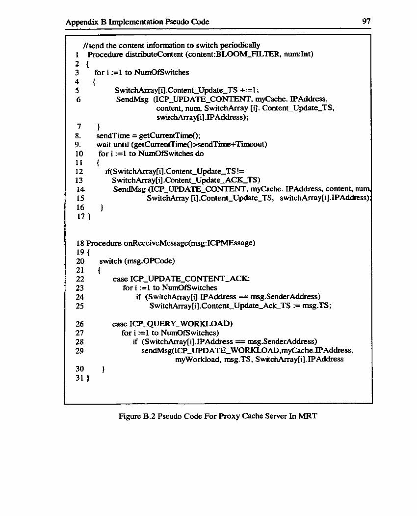
Appendix B Implementation Pseudo Code 97
//send the content information to switch periodically 1 Procedure distri'buteContent (content:BLOOM-FILTER, n w I n t ) 2
for i :=1 to NumOfSwitches
SendMsg (ICP-UPDATË-CONTENT, myCache. IPAddress, content, num, S witchkray [il. Content-Update-TS, switchArray[i] .IPAddress);
1 sendTime = getCmntTime(); wait until (getCurrentTime()>sendTime+Timeout) for i :=1 to NurnOfSwitches do {
if(S witc hArray[i] .Content-Update-TS != S witc hArray [il .Content-Update-ACK-TS) SendMsg (ICPCPUPDATE_CONTENT, myCache. IPAddress, content, num
SwitchArray [i].Content-Update-TS, switchArray[i].IPAddress)
18 Procedure onReceiveMessage(msg:ICPMEssage) 19 { 20 switch (msg.OPCode) 21 ( 22 case ICP-UPDATE-CONT'ENT-ACK: 23 for i :=1 to NumOfSwitches 24 if (S witchArray[i] .IPAddress = msg.SenderAddress) 25 S witchArray[i] .Content-Update-Ack-TS := msg.TS ;
26 case ICP-QUERY-WORKLOAD) 27 for i :=1 to NurnOfSwitches) 28 if (S witc hArray[i] .IPAddress -- rnsg .SenderAddress) 29 sendMsg(ICP_UPDATETEWORKLOAD,myCache.IPAddress,
myworkload, msg.TS, S witchArray[i] .IPAddress 30 1 31 1
Figure B.2 Pseudo Code For Roxy Cache Server In MRT

Appendix B Implementation Pseudo Code 98
The Pseudo Code for Web Server in MRT
A pseudo code description of the added update workload iùnction of a Web Server in
MRT is shown in Figure B.3. To cooperate with L5 Switches, the Web server supports
the extended ICP-UPDATE-WORKLOAD message. Lines 1 to 7 describe how a Web
server periodically sends its updated workload to L5 switches.
-- -
1. Procedure OnUpdateWorkloadTimeout () 2- 3. myworkload = getWorkload(); 4. for i :=1 to NumOfSwitches 5. if (S witc hArray[i ] JPAddress = msg SenderAddress) 6. sendMsg(ICPCPUPDATETEWORKLOAD, myIPAddress, myworkload,
S witc hArray[i] JPAddress) 7- 1
Figure B.3 Pseudo Code For Web Server In MRT
-- * a,

Appendix C Validation Check Pseudo Code 99
Appendix C
Validation Checking Pseudo Code
The foilowing pseudo code C.1 shows how W3C httpd 3.0 maintains cache consistency
(it is derived fkom study of httpd's source code).
%medure GET (P:page, S: date) 1 Answer a H l ' T P GET request. S is the date in the request's If-Modified-Since: header. 1 If there was no If-Modified-Since: header, S = -infinity. ;/ Note that the Date: and Last-Modined: headers are stored with every cached page, and /are trans~nïtted unchanged whenever a cached page is returned.
if (P in Cache & curent-time < cached-P.expiration-tirne) // in cache, no t expired
{ if (cached-P. last-modified <= S )
r e t m 'mot Modified"; Date = cached-P.date;
1 else
return cached-P 1

Appendix C Validation Check Pseudo Code 100
if (P in cache & current-time >= cached-P-expiration-time) // in cache, expired {
send If-Modified-Since(cached-P. lasttmodified) to higher level cache if (response="Not Modified) I
cached-P.expirationntime= new-expire-the); return "Not Modified"; // with headers, including Date:, as we just received them fkom higher- //level cache
1
else {
cached-p = received-P; cached-P.expiration-tirne = new-expire-time(P); re tum cac hed-P;
1 1
if (P not in cache) {
send If-Modifïed-Since(S) to Higher level cache if (whole document was retwned)
cached-P = response cached-P.expirationtitime = new-expire_time(P)
1 retum response to client, including headers
1
--
Figure C. 1 Expiration Pseudo Code

Appendix D The Simulator Stmcture 101
Appendix D
The Simulator Structure
The simulator used in our study is a discrete event-dnven simulation. It simulates the
Content, Workload, RTT, LJ3-L5 and MRT Web caching schemes. The major classes in
the simulation are as follows:
CIass Sim
Kt is the main class of the simulator. It initializes the Web clients, cache servers and the
layer 5 switches. It varies the request intensity factors to generate various controiied
traces. It runs the four simulated Web caching schernes.
CIass ClientCluster
It simulates a client cluster by readhg proxy traces to generate H T ï P requests. It handles
the TCP messages and HTTP request and response messages.
Ciass LSSwitch-ContentSwitch
It simulates a layer 5 switch used in a Content-based transparent Web caching scheme. It
redirects the requests in a round robin fashion or randomly.
C h LSSwitch-Workload

Appendix D The Simuiator Structure 102
It simulates a layer 5 switch used in a Workload-based transparent Web caching scheme.
It redirects the requests based on request content and each cache server's workload.
Ciass LSSwitch-RTT
It simulates a layer 5 switch used in a Round trip time-based transparent Web caching
scheme. It redirects the requests based on the request content and round trip time between
the switch and each cache server.
Class LSSwitch-LB-LS
It simulates a layer 5 switch used in the LB-L5 Web caching scheme.
CIass LSSwitch-MRT
It simulates a layer 5 switch used in out MRT Web caching scheme. It reditects the
requests based on the MRT selection algorithm.
Class ProxyCacheLSContent
It simulates a proxy cache server used in a Content-based transparent Web caching
scheme. It supports LRU replacement algorithm and expiration time validation checking
mechanism.
Class h x y CacheW Workload
It simulates a proxy cache server used in a Workioad-based transparent Web caching
scheme. It supports the LRU replacement algonttun and the expiration tiw validation
checking mechanism.
Ciass ProxyCacheLSRTT
It similates a proxy cache server used in a Round trip tirne-based transparent Web
caching scheme. It supports the LRU replacement algorithm and the expiration time
validation chec king mechanism.

Appendix D The Simulator Structure 103
Ciass ProxyCa~heLSLB~Ls
It simulates a proxy cache server used in the LB-L5 Web caching scheme. It supports the
LRU replacement aigorithm and the expiration time validation checking mechanisrn
Class ProxyCacheLSMRT
It simulates a proxy cache server used in our MRT Web caching scheme. It supports the
LRU replacement algorithm and the expiration time validation checking mechanism.
Class WebServer
It simulates a Web server. It accepts HTTP requests and sen& back HTïP responses. In
our simulation, the Web server &O supports the ICP messages. It periodically calculates
its current workload and sends its workload to switches with the
ICP-WDATE-WORKLOAD message.

Appendix E Confidence Intervals 104
Appendix E
Confidence Intervals
Normaliy, codidence intervals placed on the mean values of simulation results can be
used to describe the accuracy of the
statisticaily independent simulation a n s
simulation results. Consider the results of N
for the same expriment: Xi, X2, . . ., XN. The
sample mean, X is given as:
The variance of the distribution of the sample values, S: is:
s, The standard denvation of the sample rnean is given by: - JN' Under the assurnption of independence and normality, the sample mean is distributed in
accordance to the T-Distribution, which rneans the sample mean of the simulation runs

Appendix E Confidence Intervals 105 - -
f d in the interval f c within the actual mean with a certain probability drawn fiom the
T-Distribution.
whem ~ , I Z N - , is the value of the T-distribution with N-1 degrees of freedom with
probability a /2.
The upper and lower iimits of the confidence interval regarding the simulation results are:
- Sxta12.N-l Lower Limit = X -
- Upper Limit = X + S&2,N-l
f i