Transmitter and Receiver Architecture Optimized for … · Architecture Optimized for QRP Operation...
25
Transmitter and Receiver Transmitter and Receiver Architecture Optimized for Architecture Optimized for QRP Operation QRP Operation By: David Turner By: David Turner AI5EE AI5EE “ “ Knowledge unencumbered by experience. Knowledge unencumbered by experience. ” ”
-
Upload
truongliem -
Category
Documents
-
view
232 -
download
0
Transcript of Transmitter and Receiver Architecture Optimized for … · Architecture Optimized for QRP Operation...

Transmitter and Receiver Transmitter and Receiver Architecture Optimized for Architecture Optimized for
QRP OperationQRP OperationBy: David Turner By: David Turner AI5EEAI5EE
““Knowledge unencumbered by experience.Knowledge unencumbered by experience.””
What is QRPWhat is QRP
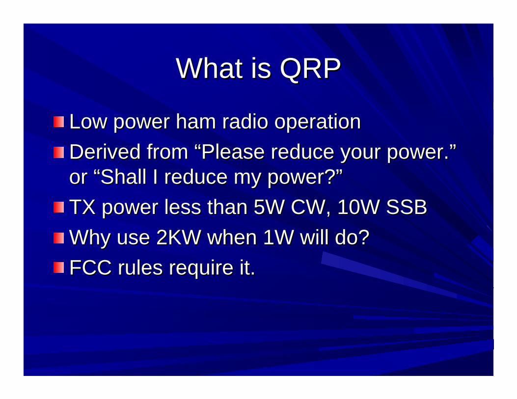
Low power ham radio operationLow power ham radio operationDerived from Derived from ““Please reduce your power.Please reduce your power.””or or ““Shall I reduce my power?Shall I reduce my power?””TX power less than 5W CW, 10W SSBTX power less than 5W CW, 10W SSBWhy use 2KW when 1W will do?Why use 2KW when 1W will do?FCC rules require it.FCC rules require it.

Optimization CriteriaOptimization Criteria
Possible ConsiderationsPossible Considerations–– Portable / battery powerPortable / battery power–– Small / light weightSmall / light weight–– SimpleSimple–– HomebrewHomebrew--ableable–– Easily repaired / adjustedEasily repaired / adjusted–– Multi band / frequency agileMulti band / frequency agile

Optimization CriteriaOptimization Criteria
The communication system The communication system must have the features must have the features
necessary to permit necessary to permit effective communication.effective communication.
Everything else is gravy.Everything else is gravy.

Proposed QRP Transmitter Proposed QRP Transmitter FeaturesFeatures
CW onlyCW onlyClean signal (no chirp, drift, warble or click)Clean signal (no chirp, drift, warble or click)Unwanted harmonics as low as reasonable Unwanted harmonics as low as reasonable (30dB below fundamental for <5W transmitter)(30dB below fundamental for <5W transmitter)Power output sufficient to be copied (in China)Power output sufficient to be copied (in China)GravyGravy
–– Efficient (for battery power operation)Efficient (for battery power operation)–– Adjustable power outputAdjustable power output–– Full break inFull break in–– built in keyerbuilt in keyer
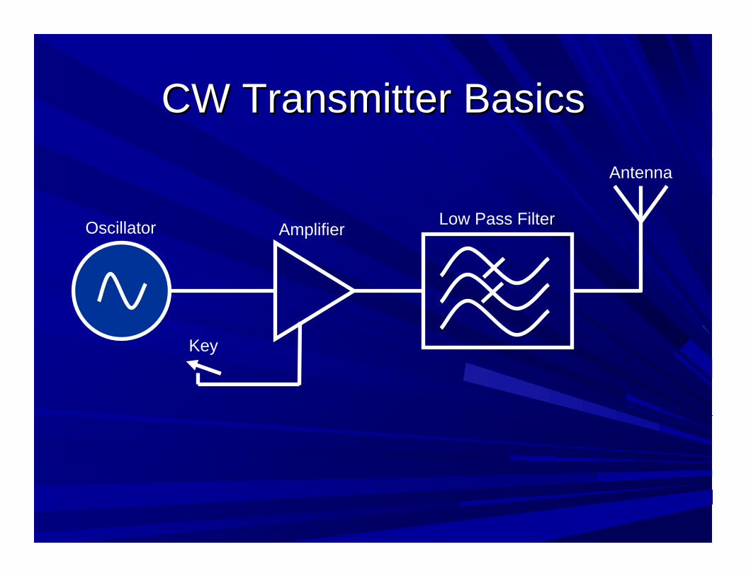
CW Transmitter BasicsCW Transmitter Basics
Oscillator Amplifier Low Pass Filter
Key
Antenna

Oscillator TypesOscillator TypesCrystalCrystal–– small bandwidthsmall bandwidth–– very stablevery stable–– easy to buildeasy to build
LC ResonatorLC Resonator–– drift (must be temperature compensated)drift (must be temperature compensated)–– large bandwidthlarge bandwidth–– easy to buildeasy to build

Oscillator TypesOscillator Types
Direct Digital SynthesisDirect Digital Synthesis–– Stable (crystal controlled)Stable (crystal controlled)–– Controllable phaseControllable phase–– Must interface to a microprocessorMust interface to a microprocessor–– Output contains many spurious outputsOutput contains many spurious outputs–– Larger power drainLarger power drain–– Limited output frequency (12 MHz easily, 33 Limited output frequency (12 MHz easily, 33
MHz not so easilyMHz not so easily

Amplifier TypesAmplifier Types
Amplifier type (generally) designated by Amplifier type (generally) designated by how long the transistor conducts during the how long the transistor conducts during the RF periodRF periodClass A (100% of RF period)Class A (100% of RF period)–– very linearvery linear–– very inefficient (30very inefficient (30--50%)50%)
Class AB (~75% of RF period)Class AB (~75% of RF period)–– worse linearityworse linearity–– better efficiencybetter efficiency

Amplifier TypesAmplifier Types
Class C (<50% of RF period)Class C (<50% of RF period)–– Not linear (not usable for SSB communication)Not linear (not usable for SSB communication)–– Fine for CW (with a filter)Fine for CW (with a filter)–– More efficientMore efficient
Class DClass D–– Uses pushUses push--pull transistors in a pull transistors in a ““digitaldigital”” mode mode
(think pulse width modulation)(think pulse width modulation)–– More Efficient (transistor either fully on or fully More Efficient (transistor either fully on or fully
off).off).

Amplifier TypesAmplifier Types
Class EClass E–– Most efficient (can be 90% or better)Most efficient (can be 90% or better)–– Transistor either fully on or fully offTransistor either fully on or fully off–– Tuned output prevents the simultaneous Tuned output prevents the simultaneous
application of high voltage and high current to application of high voltage and high current to transistortransistor
–– Tuned output allows power greater than Vdd Tuned output allows power greater than Vdd into 50 ohmsinto 50 ohms
–– Not linearNot linear

Receiver OptimizationReceiver Optimization
Low noise floorLow noise floorLow power drawLow power drawMinimal LO driftMinimal LO driftReject AM interferenceReject AM interferenceSensitivity <.1 microvoltSensitivity <.1 microvolt
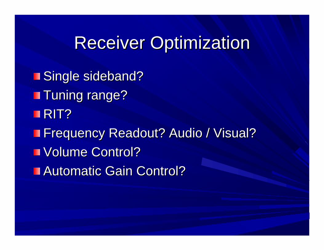
Receiver OptimizationReceiver Optimization
Single sideband?Single sideband?Tuning range?Tuning range?RIT?RIT?Frequency Readout? Audio / Visual?Frequency Readout? Audio / Visual?Volume Control?Volume Control?Automatic Gain Control?Automatic Gain Control?

Receiver ArchitectureReceiver Architecture
General typesGeneral types–– Direct ConversionDirect Conversion–– RegenerativeRegenerative–– SuperheterodyneSuperheterodyne–– PhasingPhasing
HartleyHartleyWeaverWeaver

Direct ConversionDirect Conversion
SimpleSimpleLow parts countLow parts countEasy to buildEasy to buildClean audio (no birdies)Clean audio (no birdies)Dual sideband onlyDual sideband only

RegenerativeRegenerative
SimpleSimpleLow parts countLow parts countDual sideband Dual sideband onlyonlySensitive to Sensitive to ““Hand Hand CapacitanceCapacitance””
http://web.telia.com/~u43200663/rx/bipol_regen_rx.htm
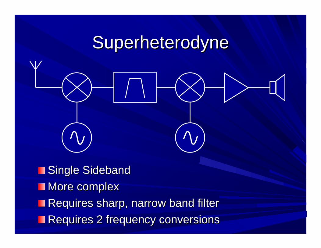
SuperheterodyneSuperheterodyne
Single SidebandSingle SidebandMore complexMore complexRequires sharp, narrow band filterRequires sharp, narrow band filterRequires 2 frequency conversionsRequires 2 frequency conversions

Hartley Phasing ReceiverHartley Phasing ReceiverSee Rick Campbell KK7B's work.See Rick Campbell KK7B's work.
Single SidebandSingle SidebandRequires precise phase shift networkRequires precise phase shift networkRequires two mixersRequires two mixers
Sin
Cos
90 deg.
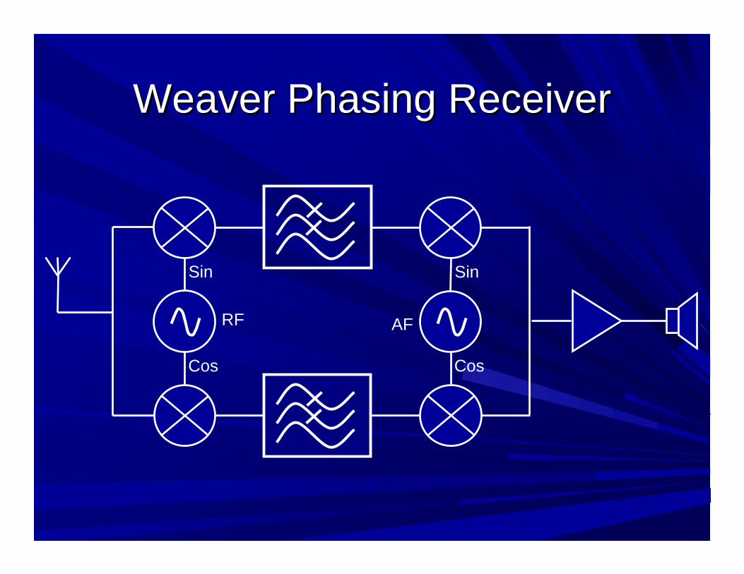
Weaver Phasing ReceiverWeaver Phasing Receiver
Sin
Cos
Sin
Cos
RF AF

Weaver Phasing ReceiverWeaver Phasing Receiver
Single sideband receptionSingle sideband receptionNo sharp RF filter or phase shift networkNo sharp RF filter or phase shift networkSame architecture can be used for SSB Same architecture can be used for SSB generationgenerationAF oscillator is fixed frequency (center of AF oscillator is fixed frequency (center of audio passband)audio passband)Requires 4 mixersRequires 4 mixers

Quadrature Mixer (Tayloe Style)Quadrature Mixer (Tayloe Style)
0 deg.
90 deg.
180 deg.
270 deg.
RF
counter4*LO
Audio Frequency
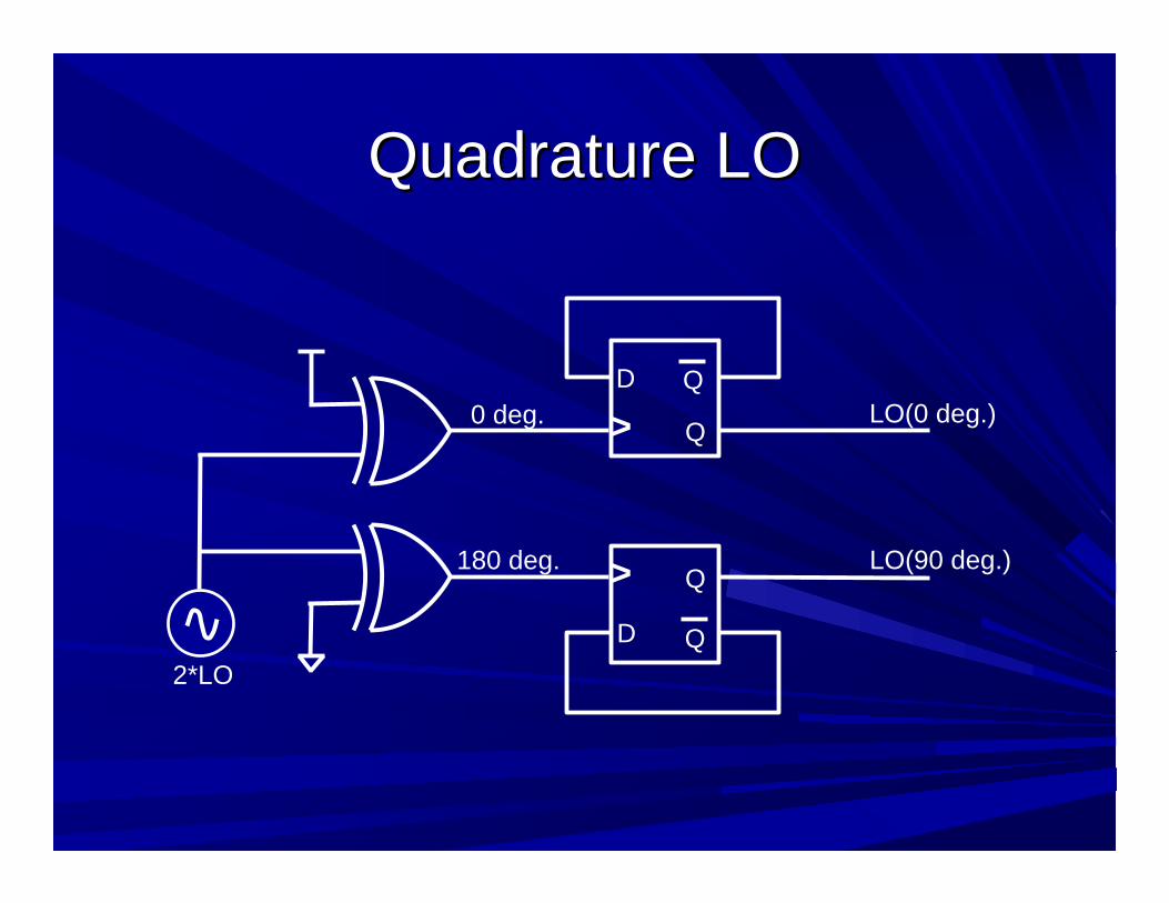
Quadrature LOQuadrature LO
2*LO
0 deg.
180 deg.
Q
QD
>
Q
QD
>
LO(0 deg.)
LO(90 deg.)

Quadrature LO TimingQuadrature LO Timing
2*LO
0
180
QQD>QQD
>
LO(0 deg.)
LO(90 deg.)
2*LO
0 DEG
180 DEG
LO(0)
LO(90)
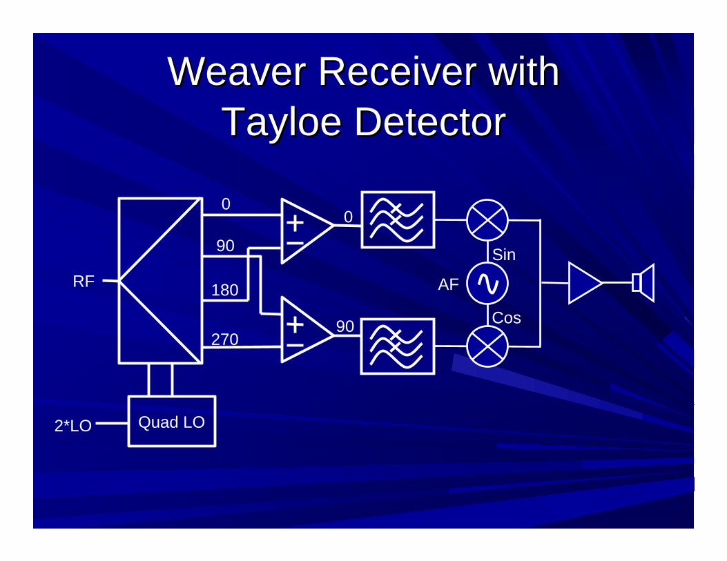
Weaver Receiver with Weaver Receiver with Tayloe DetectorTayloe Detector
RF
Quad LO2*LO
0
90
180
270
Sin
Cos
AF
0
90

Hartley Receiver with Hartley Receiver with Tayloe DetectorTayloe Detector
Polyphase 90 degree phase shifterPolyphase 90 degree phase shifter
http://home.planet.nl/~niess153/Polyphase_networks/Understanding_and_designing_Polyphase_networks_V3.5.pdf


![QRP - start [285 TechConnect Radio Club -- NAØTC]QRP-optimized rig Receive -100 milliamps…Xmit -500 milliamps TOTAL CONSUMPTION -3.36 A-H (a 3-lb. gel cell) QRP Kitbuilding & Homebrewing](https://static.fdocuments.us/doc/165x107/5f89d6df996ba755b01d6b3a/qrp-start-285-techconnect-radio-club-natc-qrp-optimized-rig-receive-100.jpg)