Transmitted light laboratory microscope...
27
OBD-1-BA-e-1510 KERN & Sohn GmbH Ziegelei 1 D-72336 Balingen E-Mail: [email protected] Tel: +49-[0]7433- 9933-0 Fax: +49-[0]7433-9933-149 Internet: www.kern-sohn.com User instructions Transmitted light laboratory microscope (digital) KERN OBD-1 OBD 127, OBD 128 Version 1.0 01/2015
-
Upload
duongkhanh -
Category
Documents
-
view
213 -
download
0
Transcript of Transmitted light laboratory microscope...

OBD-1-BA-e-1510
KERN & Sohn GmbH Ziegelei 1 D-72336 Balingen E-Mail: [email protected]
Tel: +49-[0]7433- 9933-0 Fax: +49-[0]7433-9933-149 Internet: www.kern-sohn.com
User instructions Transmitted light laboratory microscope (digital)
KERN OBD-1 OBD 127, OBD 128
Version 1.0 01/2015

OBD-1-BA-e-1510 2
GB KERN OBD-1 Version 1.0 01/2015
User instructions Transmitted light microscope (digital)
Table of contents
1 Before use .................................................................................... 3 1.1 General notes ............................................................................................................................ 3 1.2 Notes on the electrical system ................................................................................................ 3 1.3 Storage ...................................................................................................................................... 4 1.4 Maintenance and cleaning ....................................................................................................... 5
2 Nomenclature ............................................................................... 6
3 Technical data / Features ............................................................ 8
4 Assembly .................................................................................... 10 4.1 Microscope head .................................................................................................................... 10 4.2 Objectives ............................................................................................................................... 10 4.3 Eyepieces ................................................................................................................................ 10 4.4 Colour filter ............................................................................................................................. 10 4.5 Condenser ............................................................................................................................... 11
5 Operation .................................................................................... 11 5.1 Getting started ........................................................................................................................ 11 5.2 (Pre-) focussing ...................................................................................................................... 12 5.3 Adjusting the interpupillary distance ................................................................................... 13 5.4 Dioptre adjustment ................................................................................................................. 13 5.5 Adjusting the magnification .................................................................................................. 14 5.6 Adjusting the Koehler illumination ....................................................................................... 15 5.7 Using the camera .................................................................................................................... 17 5.8 Using eye cups ....................................................................................................................... 18 5.9 Using oil immersion objectives ............................................................................................ 19
6 Changing the bulb ..................................................................... 20
7 Changing the fuse ...................................................................... 21
8 Using optional accessories ....................................................... 21 8.1 Polarisation unit ..................................................................................................................... 21 8.2 Dark field units ........................................................................................................................ 22 8.3 Phase-contrast unit ................................................................................................................ 22
9 Trouble shooting ........................................................................ 24
10 Service ........................................................................................ 26
11 Disposal ...................................................................................... 26
12 Further information .................................................................... 26

3 OBD-1-BA-e-1510
1 Before use
1.1 General notes
You must open the packaging carefully, to make sure that none of the accessories in the packaging fall on the floor and get broken. In general, microscopes should always be handled carefully because they are sensitive precision instruments. When using or transporting the microscope it is particularly important to avoid abrupt movements, as this may damage the optical components. You should also avoid getting dirt or finger prints on the lens surface, because in most cases this will reduce image clarity. To maintain the performance of the microscope, it must never be disassembled. So components such as lenses and other optical elements should be left as they were before use. Also the electrical parts on the rear and base of the device must not be tampered with, as in this area there is an additional risk of triggering an electric shock.
1.2 Notes on the electrical system
Before connecting to a mains power supply, you must make sure that you are using the correct input voltage. The information to select the correct mains cable is located on the device, on the rear of the product directly above the connection socket. You must comply with this information. If you do not comply with these specifications, then fires or other damage to the device could occur. The main switch must also be switched off before the mains cable is connected. In this way you will avoid triggering an electric shock. If you are using an extension cable, then the mains cable you use must be earthed. If the original fuse should blow, it must only be replaced by an appropriate fuse. Suitable replacement fuses are included with the delivery. When carrying out any procedures whereby you come into contact with the electrical system of the device, such as, for example, changing the bulb or fuse, only carry out these procedures when the power is disconnected.

OBD-1-BA-e-1510 4
Under no circumstances should you touch the integrated halogen bulbs either during operation or directly after use. These bulbs produce significant heat and therefore there is a risk that the user could be severely burnt. So before handling the bulbs, you must check that they have cooled down. The microscope housing, on the other hand, is constructed so that no significant heat radiation emanates from the device and that there is absolutely no risk of the user burning themselves from the housing outer surfaces.
1.3 Storage
You should ensure that the device is not exposed to direct sunlight, temperatures which are too high or too low, vibrations, dust or a high level of humidity. The ideal temperature range is between 0 and 40°C and a relative humidity of 85% should not be exceeded. The device should always be located on a rigid, smooth, horizontal surface. When the microscope is not being used, you should cover it with the enclosed dust protective cover. When doing this, the power supply is stopped by switching off at the main switch and unplugging the mains cable. If the eyepieces are being stored separately, the protective caps must be fitted to the tube connectors. In most cases, if dust and dirt gets inside the optical unit of a microscope this can cause irreversible errors or damage. The best way to store accessories which consist of optical elements, such as, for example, eyepieces and objectives, is in a dry box with desiccant.
5 OBD-1-BA-e-1510
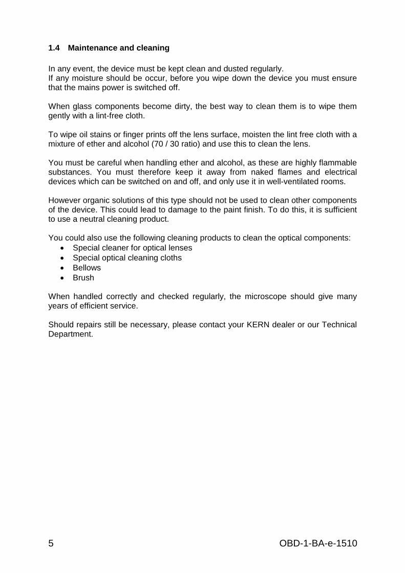
1.4 Maintenance and cleaning
In any event, the device must be kept clean and dusted regularly. If any moisture should be occur, before you wipe down the device you must ensure that the mains power is switched off. When glass components become dirty, the best way to clean them is to wipe them gently with a lint-free cloth. To wipe oil stains or finger prints off the lens surface, moisten the lint free cloth with a mixture of ether and alcohol (70 / 30 ratio) and use this to clean the lens. You must be careful when handling ether and alcohol, as these are highly flammable substances. You must therefore keep it away from naked flames and electrical devices which can be switched on and off, and only use it in well-ventilated rooms. However organic solutions of this type should not be used to clean other components of the device. This could lead to damage to the paint finish. To do this, it is sufficient to use a neutral cleaning product. You could also use the following cleaning products to clean the optical components:
Special cleaner for optical lenses
Special optical cleaning cloths
Bellows
Brush When handled correctly and checked regularly, the microscope should give many years of efficient service. Should repairs still be necessary, please contact your KERN dealer or our Technical Department.
OBD-1-BA-e-1510 6
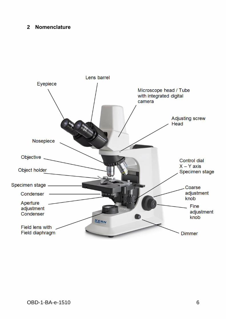
2 Nomenclature

7 OBD-1-BA-e-1510
Rear view
OBD-1-BA-e-1510 8
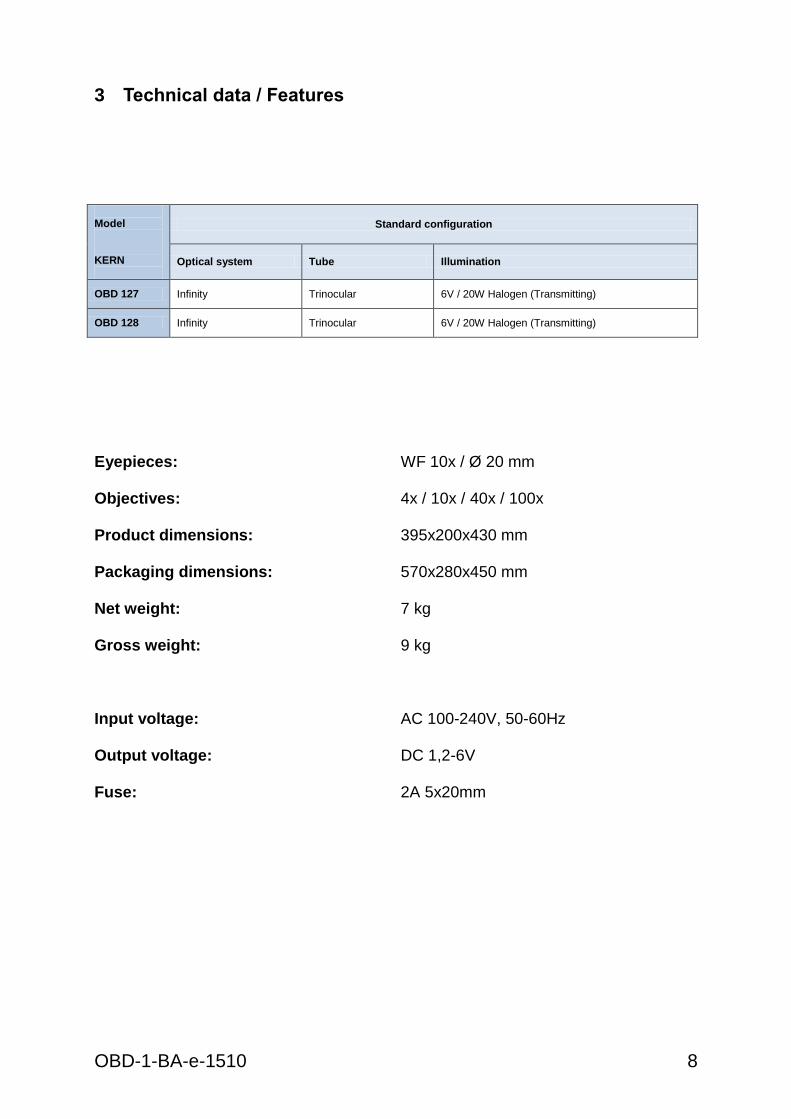
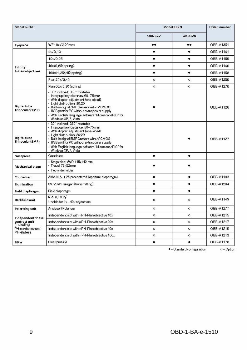
3 Technical data / Features
Model KERN
Standard configuration
Optical system Tube Illumination
OBD 127 Infinity Trinocular 6V / 20W Halogen (Transmitting)
OBD 128 Infinity Trinocular 6V / 20W Halogen (Transmitting)
Eyepieces: WF 10x / Ø 20 mm
Objectives:
4x / 10x / 40x / 100x
Product dimensions:
395x200x430 mm
Packaging dimensions:
570x280x450 mm
Net weight:
7 kg
Gross weight:
9 kg
Input voltage: AC 100-240V, 50-60Hz Output voltage:
DC 1,2-6V
Fuse:
2A 5x20mm
9 OBD-1-BA-e-1510

OBD-1-BA-e-1510 10
4 Assembly
4.1 Microscope head
First you must loosen the fixing screw on the tube connection point and remove the black protective cover. You can then insert the round dovetail bracket on the head into the round dovetail bracket on the housing and fix it with the fixing screw. When doing this, you should always make sure that you do not touch the lenses with your bare fingers and that no dust enters the apertures.
4.2 Objectives
All four objectives are already mounted to the nosepiece. After removing the protective foil they are ready for use. They are ranged in such a way that if you turn the nosepiece clockwise, the objective with the next higher magnification appears. When the objectives need to be dismounted, you should always make sure that you do not touch the lenses with your bare fingers and that no dust enters the apertures. For objectives which are marked “OIL”, you must use an immersion oil with the lowest level of inherent fluorescence.
4.3 Eyepieces
You must always use eyepieces with the same magnification for both eyes. These are simply placed onto the tube connectors, once you have first removed the plastic protective caps. There is no way of fixing them. You should always make sure that you do not touch the lenses with your bare fingers and that no dust enters the apertures.
4.4 Colour filter
A blue colour filter is already an integral part of the microscopes of the series OBD-1. It is fitted underneath the field diaphragm. In order to use suitable filters, these can simply be placed in the ring bracket of the field lens.
11 OBD-1-BA-e-1510
4.5 Condenser
We recommend that you use the course adjustment knob to bring the specimen stage to its uppermost position. Use the focus dial of the condenser to move the condenser holder to the central position. In this way the condenser can be fitted at the right place in the condenser holder and fixed with the adjusting screw. When doing this, you should be able to read the scale from the front. You should avoid touching the optical lenses with bare fingers.
5 Operation
5.1 Getting started
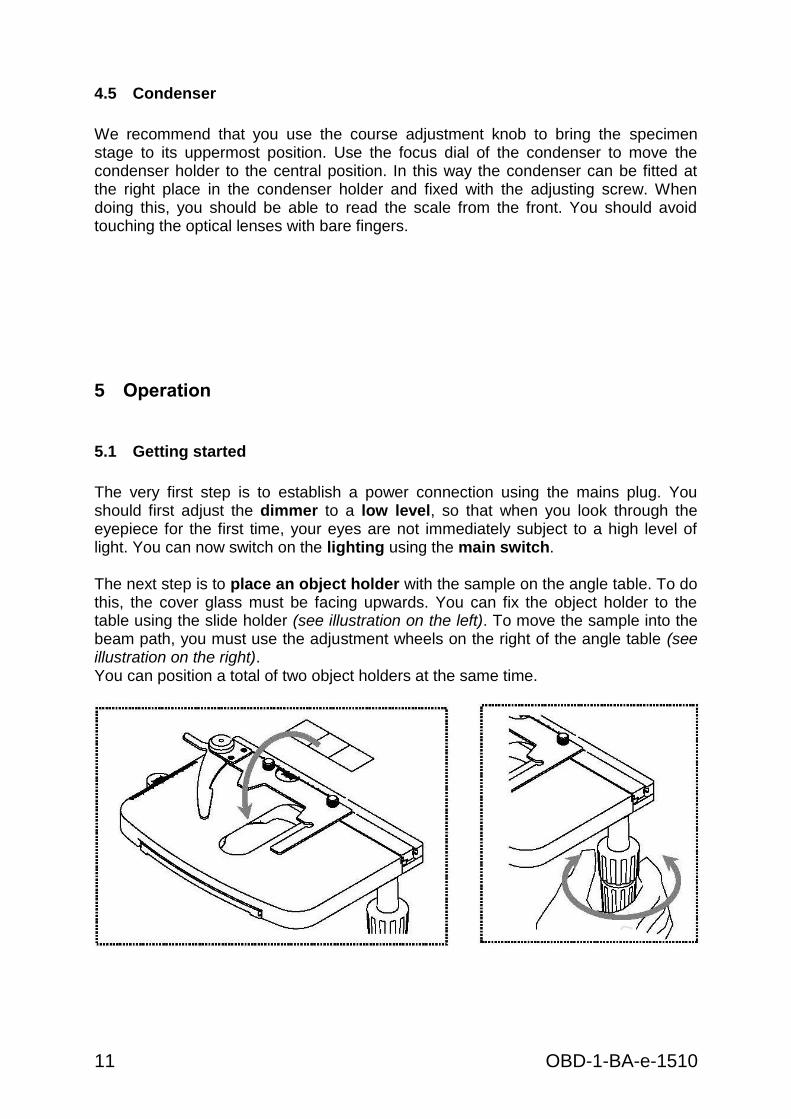
The very first step is to establish a power connection using the mains plug. You should first adjust the dimmer to a low level, so that when you look through the eyepiece for the first time, your eyes are not immediately subject to a high level of light. You can now switch on the lighting using the main switch. The next step is to place an object holder with the sample on the angle table. To do this, the cover glass must be facing upwards. You can fix the object holder to the table using the slide holder (see illustration on the left). To move the sample into the beam path, you must use the adjustment wheels on the right of the angle table (see illustration on the right). You can position a total of two object holders at the same time.
OBD-1-BA-e-1510 12
5.2 (Pre-) focussing
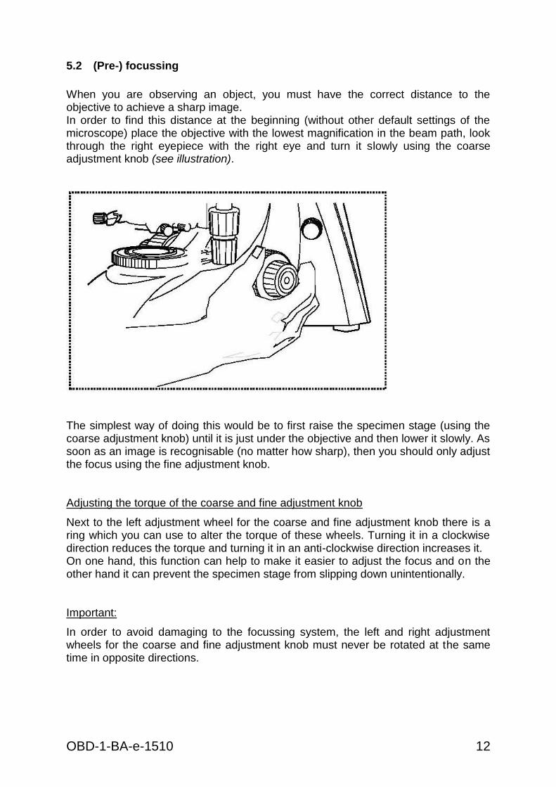
When you are observing an object, you must have the correct distance to the objective to achieve a sharp image. In order to find this distance at the beginning (without other default settings of the microscope) place the objective with the lowest magnification in the beam path, look through the right eyepiece with the right eye and turn it slowly using the coarse adjustment knob (see illustration).
The simplest way of doing this would be to first raise the specimen stage (using the coarse adjustment knob) until it is just under the objective and then lower it slowly. As soon as an image is recognisable (no matter how sharp), then you should only adjust the focus using the fine adjustment knob. Adjusting the torque of the coarse and fine adjustment knob
Next to the left adjustment wheel for the coarse and fine adjustment knob there is a ring which you can use to alter the torque of these wheels. Turning it in a clockwise direction reduces the torque and turning it in an anti-clockwise direction increases it. On one hand, this function can help to make it easier to adjust the focus and on the other hand it can prevent the specimen stage from slipping down unintentionally. Important:
In order to avoid damaging to the focussing system, the left and right adjustment wheels for the coarse and fine adjustment knob must never be rotated at the same time in opposite directions.

13 OBD-1-BA-e-1510
5.3 Adjusting the interpupillary distance
With binocular viewing, the interpupillary distance must be adjusted accurately for each user, in order to achieve a clear image of the object. While you are looking through the eyepieces, use your hands to hold the righthand and lefthand tube housing firmly. By pulling them apart or pushing them together, you can either increase or reduce the interpupillary distance (see illustration). As soon as the field of views of the lefthand and righthand eyepieces completely overlap each other, i.e. they combine to form a circular image, then the interpupillary distance is set correctly.
5.4 Dioptre adjustment
The eye strengths of each eye of the microscope user can often be slightly different, which in daily life has no consequences. But when using a microscope this can cause problems in achieving precise focussing. You can use a mechanism on the left tube connector (dioptre adjustment ring) to compensate for this as follows.
1. Look through the right eyepiece with the right eye and bring the object into focus by using the coarse and fine adjustment knob.
2. Then look through the left eyepiece with the left eye and use the dioptre adjustment ring to focus the image. To do this, you just need to turn the ring in both directions (see illustration), to find out where the image is at its most focussed.
OBD-1-BA-e-1510 14
5.5 Adjusting the magnification
After prefocussing has been carried out using the objective with the lowest magnification (see section 5.2), you can then adjust the overall magnification using the nosepiece, as necessary. By turning the nosepiece you can bring any one of the four other objectives into the beam path. When adjusting the nosepiece, you must take the following points into account: - The required objective must be properly locked in
place at all times.
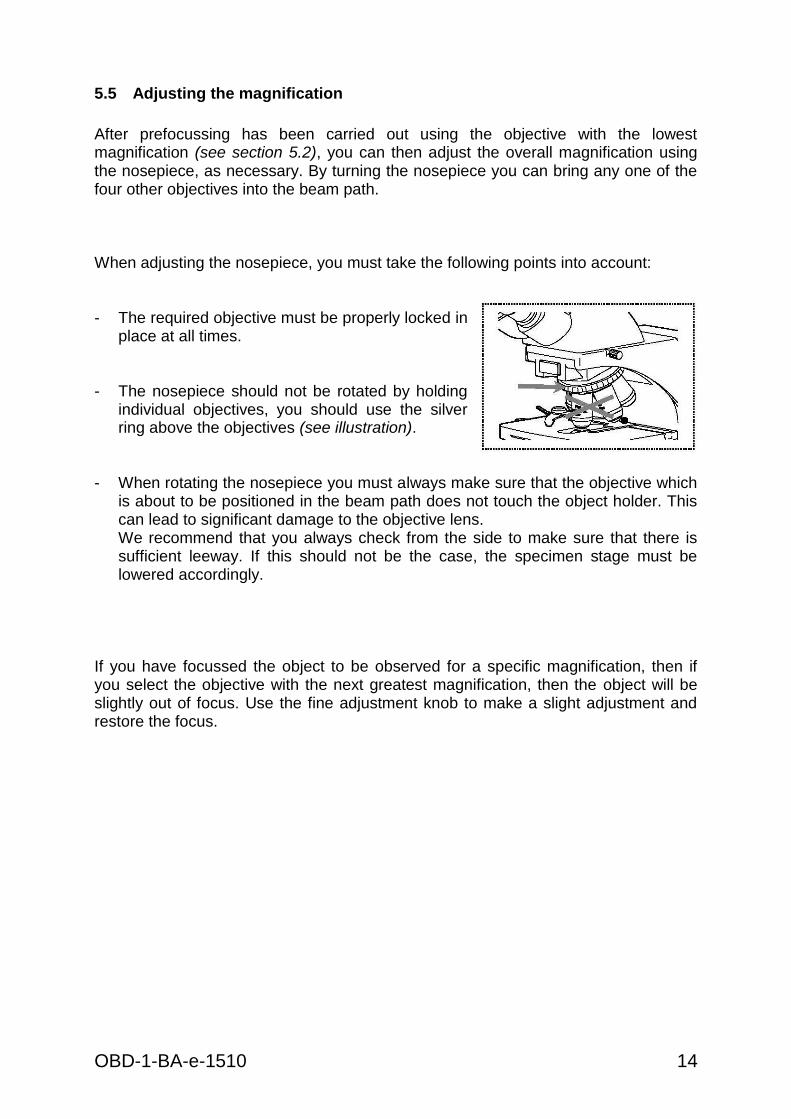
- The nosepiece should not be rotated by holding individual objectives, you should use the silver ring above the objectives (see illustration).
- When rotating the nosepiece you must always make sure that the objective which
is about to be positioned in the beam path does not touch the object holder. This can lead to significant damage to the objective lens. We recommend that you always check from the side to make sure that there is sufficient leeway. If this should not be the case, the specimen stage must be lowered accordingly.
If you have focussed the object to be observed for a specific magnification, then if you select the objective with the next greatest magnification, then the object will be slightly out of focus. Use the fine adjustment knob to make a slight adjustment and restore the focus.
15 OBD-1-BA-e-1510
5.6 Adjusting the Koehler illumination
To make sure that perfect image results are achieved during microscopic observation, it is important that the direction of light of the microscope is optimised. If, as with the devices in the KERN OBD-1 series, the lighting can be set in accordance with Koehler, the result is homogenous illumination of the slide and avoidance of disruptive stray light. The necessary control elements for this are:
Height-adjustable and centre-adjustable condenser with aperture diaphragm
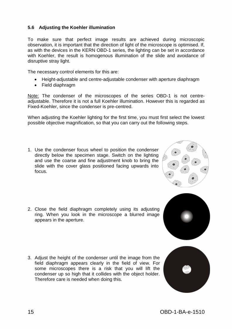
Field diaphragm Note: The condenser of the microscopes of the series OBD-1 is not centre-adjustable. Therefore it is not a full Koehler illumination. However this is regarded as Fixed-Koehler, since the condenser is pre-centred. When adjusting the Koehler lighting for the first time, you must first select the lowest possible objective magnification, so that you can carry out the following steps. 1. Use the condenser focus wheel to position the condenser
directly below the specimen stage. Switch on the lighting and use the coarse and fine adjustment knob to bring the slide with the cover glass positioned facing upwards into focus.
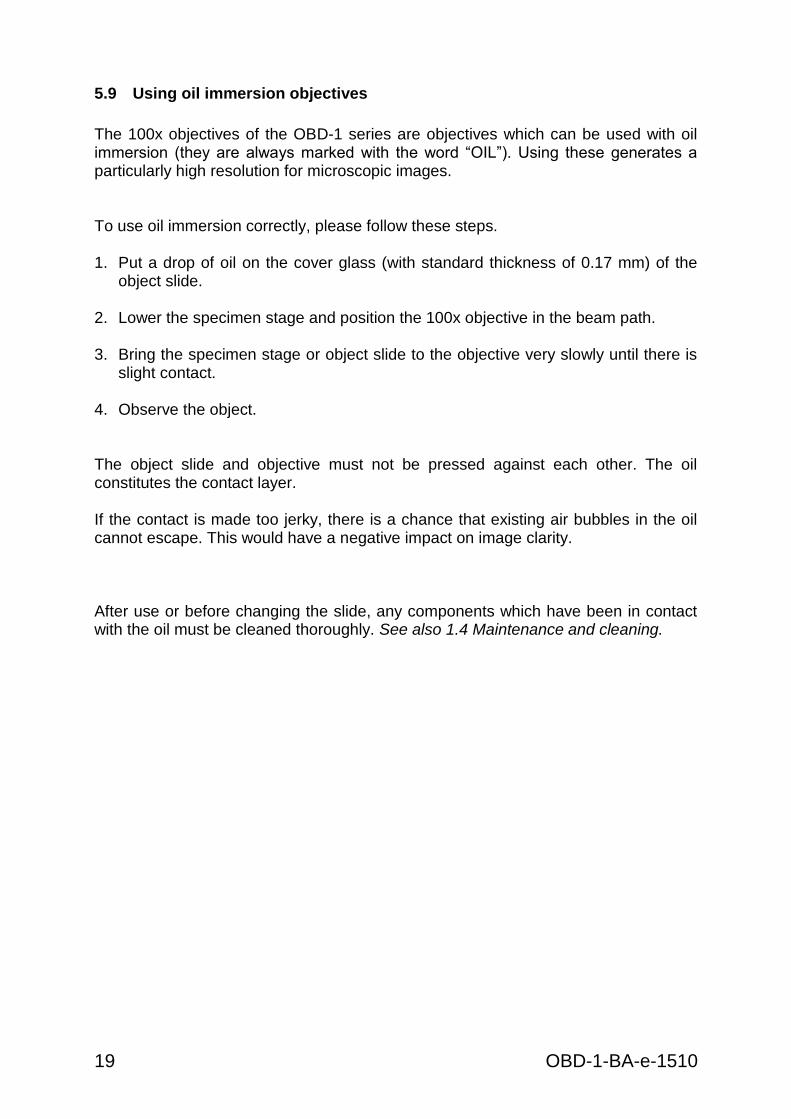
2. Close the field diaphragm completely using its adjusting
ring. When you look in the microscope a blurred image appears in the aperture.
3. Adjust the height of the condenser until the image from the
field diaphragm appears clearly in the field of view. For some microscopes there is a risk that you will lift the condenser up so high that it collides with the object holder. Therefore care is needed when doing this.

OBD-1-BA-e-1510 16
4. Open the field diaphragm until it just disappears out of the field of view. If necessary, simply re-centre using the centring screws on the condenser holder.
5. Use the aperture diaphragm of the condenser to find the
very best compromise between contrast and resolution for the microscopic image. The scale divisions on the condenser can be used as a guideline. Select in accordance with the objective being used.
The view in the tube without the eyepiece should look something like the illustration on the right. The diameter of the aperture diaphragm which is then visible should make up approximately 2/3 of the pupil diameter.
If the eyepiece should be removed, for checking, then please make sure that no dirt or dust falls into the tube.
6. It is possible to alter the brightness of the bulb using the dimmer. The brightness
is always controlled by the bulb brightness and not by the aperture diaphragm. 7. Possibly there is the need of re-adjusting the focus and x-y axis. 8. Observe the object. If another magnification is selected afterwards, then the Koehler illumination does not have to be reset from scratch, only the aperture diaphragm and field diaphragm need to be adjusted as required.

17 OBD-1-BA-e-1510
5.7 Using the camera
The devices of the OBD-1 series are standardly equipped with heads, which have integrated digital microscope cameras. Thus images or sequences of an object can be measured or digitally documented easily. Scope of delivery:
- USB cable - Software disk - Micrometre slide (for calibration)
Specifications of camera + software:
Image size OBD 127 3 MP
Image size OBD 128 5 MP
Sensor CMOS
Sensor size OBD 127 1/2“
Sensor size OBD 128 1/2,5“
PC interface USB 2.0
Suitable operating system Windows XP, Vista, 7, 8, 10
Software language English
In order to run the camera appropriately you must establish a connection between the USB port of the camera and an USB port of a PC. The needed cable is included in the scope of delivery. Furthermore there is also a disk that enables you to install the software (incl. driver) on the PC. When running the program there are many tools for displaying and documenting images. The precise instructions can be found using the integrated user guide. Mainly that is needed if the user would like to do a calibration in order to carry out measurements. Due to the light distribution of 80:20 inside the digital microscope head you can always observe a sample by the eyepieces and the PC display at the same time. We recommend adjusting at first the field of view of the eyepieces according to the requirements. After that you can begin the observation by the camera.

OBD-1-BA-e-1510 18
5.8 Using eye cups
The eye cups supplied with the microscope can basically be used at all times, as they screen out intrusive light, which is reflected from light sources from the environment onto the eyepiece, and the result is better image quality. But primarily, if eyepieces with a high eye point (particularly suitable for those who wear glasses) are used, then it may also be useful for users who don’t wear glasses, to fit the eye cups to the eyepieces. These special eyepieces are also called High Eye Point eyepieces. They can be identified by the glasses symbol on the side. They are also marked in the item description by an additional “H” (example: HSWF 10x Ø 23 mm). When fitting the eye cups, make sure that the dioptre setting is not moved. We would therefore advise that you hold the dioptre compensation ring on an eyepiece with one hand while you fit the eye cup with the other. Before using the microscope, users who wear glasses must remove the eye cups, which you may find on High Eye Point eyepieces. As the eye cups are made of rubber, you must be aware that when you are using them, they can become slightly dirty through grease residues. In order to maintain hygiene, we would therefore recommend that you clean the eye cups regularly (e.g. with a damp cloth).
Eye cups
High Eye Point eyepiece (identified by the glasses symbol)
19 OBD-1-BA-e-1510
5.9 Using oil immersion objectives
The 100x objectives of the OBD-1 series are objectives which can be used with oil immersion (they are always marked with the word “OIL”). Using these generates a particularly high resolution for microscopic images. To use oil immersion correctly, please follow these steps. 1. Put a drop of oil on the cover glass (with standard thickness of 0.17 mm) of the
object slide.
2. Lower the specimen stage and position the 100x objective in the beam path.
3. Bring the specimen stage or object slide to the objective very slowly until there is slight contact.
4. Observe the object. The object slide and objective must not be pressed against each other. The oil constitutes the contact layer.
If the contact is made too jerky, there is a chance that existing air bubbles in the oil cannot escape. This would have a negative impact on image clarity. After use or before changing the slide, any components which have been in contact with the oil must be cleaned thoroughly. See also 1.4 Maintenance and cleaning.
OBD-1-BA-e-1510 20
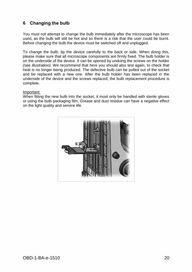
6 Changing the bulb
You must not attempt to change the bulb immediately after the microscope has been used, as the bulb will still be hot and so there is a risk that the user could be burnt. Before changing the bulb the device must be switched off and unplugged. To change the bulb, tip the device carefully to the back or side. When doing this, please make sure that all microscope components are firmly fixed. The bulb holder is on the underside of the device. It can be opened by undoing the screws on the holder (see illustration). We recommend that here you should also test again, to check that heat is no longer being produced. The defective bulb can be pulled out of the socket and be replaced with a new one. After the bulb holder has been replaced in the underside of the device and the screws replaced, the bulb replacement procedure is complete. Important: When fitting the new bulb into the socket, it must only be handled with sterile gloves or using the bulb packaging film. Grease and dust residue can have a negative effect on the light quality and service life.
21 OBD-1-BA-e-1510
7 Changing the fuse
The fuse housing is on the rear of the microscope below the mains power supply socket. With the device switched off and unplugged, you can pull out the housing. When doing this, it is helpful to use a screwdriver or similar tool. The defective fuse can be removed from its housing and be replaced with a new one. After that, you just need to insert the fuse housing back into the insertion point below the mains power supply socket.
8 Using optional accessories
8.1 Polarisation unit
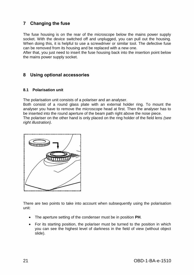
The polarisation unit consists of a polariser and an analyser. Both consist of a round glass plate with an external holder ring. To mount the analyser you have to remove the microscope head at first. Then the analyser has to be inserted into the round aperture of the beam path right above the nose piece. The polariser on the other hand is only placed on the ring holder of the field lens (see right illustration).
There are two points to take into account when subsequently using the polarisation unit:
The aperture setting of the condenser must be in position PH.
For its starting position, the polariser must be turned to the position in which you can see the highest level of darkness in the field of view (without object slide).
OBD-1-BA-e-1510 22
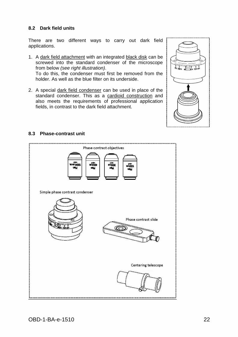
8.2 Dark field units
There are two different ways to carry out dark field applications. 1. A dark field attachment with an integrated black disk can be
screwed into the standard condenser of the microscope from below (see right illustration). To do this, the condenser must first be removed from the holder. As well as the blue filter on its underside.
2. A special dark field condenser can be used in place of the standard condenser. This as a cardioid construction and also meets the requirements of professional application fields, in contrast to the dark field attachment.
8.3 Phase-contrast unit
23 OBD-1-BA-e-1510
Simple phase-contrast unit
This consists of a simple PH condenser, a PH objective with a specific magnification (10x, 20x, 40x or 100x), a PH slider, which is adapted to the lens being used, a centring telescope and two green filters. To use this, you need to replace the standard condenser of the microscope with the PH condenser. One of the objectives in the nosepiece is also replaced with the PH objective and this is positioned in the beam path. With the surface marked “TOP” facing up, the PH slider is pushed upwards into the insertion point on the PH condenser until it clicks into the first position. At this first position, the phase ring of the PH slider is in the beam path. If the aperture setting on the PH condenser is set to “PH”, then the phase-contrast application can begin. In order to return to the bright field application, you must push the PH slider further to the second click position. At this point there is no PH ring as in position 1; the beam can pass without being affected by the PH slider.
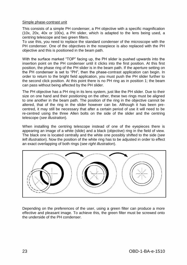
The PH objective has a PH ring in its lens system, just like the PH slider. Due to their size on one hand and their positioning on the other, these two rings must be aligned to one another in the beam path. The position of the ring in the objective cannot be altered, that of the ring in the slider however can be. Although it has been pre-centred, it may still be necessary that after a certain period of use it will need to be re-centred using the three Allen bolts on the side of the slider and the centring telescope (see illustration). When installing the centring telescope instead of one of the eyepieces there is appearing an image of a white (slide) and a black (objective) ring in the field of view. The black one is located centrally and the white one possibly shifted to the side (see left illustration). Now the position of the white ring has to be adjusted in order to effect an exact overlapping of both rings (see right illustration).
Depending on the preferences of the user, using a green filter can produce a more effective and pleasant image. To achieve this, the green filter must be screwed onto the underside of the PH condenser.

OBD-1-BA-e-1510 24
9 Trouble shooting
Problem Possible causes
The bulb does not light
The mains plug is not correctly plugged in
There is no power at the socket
Defective bulb
Defective fuse
The bulb blows immediately The specified bulb or fuse has not been used
The field of view is dark
The aperture diaphragm and/or field diaphragm are not opened wide enough
The selector switch for the beam path is set to “Camera”
The condenser is not correctly centred
You cannot adjust the brightness
The brightness control has been set incorrectly
The condenser has not been correctly centred
The condenser is too low
The field of view is dark or is not correctly illuminated
The objective is not positioned correctly on the beam path
The selector switch for the beam path is between two settings
The nosepiece is not correctly fitted
The condenser is not correctly fitted
An objective is being used which doesn’t match the lighting area of the condenser
The condenser has not been correctly centred
The field diaphragm is closed too tightly
The bulb is not correctly fitted
The field of view of one eye does not match that of the other eye
The interpupillary distance is not correctly adjusted
Dioptre setting has not been carried out correctly
Different eyepieces are used for the righthand and lefthand side
The eyes are not used to using a microscope

25 OBD-1-BA-e-1510
Problem Possible causes
Blurred details Bad image Bad contrast Vignetted field of view
The aperture diaphragm is not opened wide enough
The condenser is too low
The objective does not belong to this microscope
The front lens of the objective is dirty
An immersion object has been used without immersion oil
The immersion oil contains air bubbles
The condenser is not correctly centred
The recommended immersion oil has not been used
Dirt / dust on the objective
Dirt /dust on the front lens of the condenser
Dirt or dust in the field of view
Dirt / dust on the eyepieces
Dirt / dust on the front lens of the condenser
Dirt / dust on the object
One side of the image is blurred
The stage was not correctly fitted
The objective is not positioned correctly on the beam path
The nosepiece is not correctly fitted
The upper side of the object is facing down
The image flickers
The nosepiece is not correctly fitted
The objective is not positioned correctly on the beam path
The condenser has not been correctly centred
The coarse adjustment knob is difficult to turn
The rotational resistance brake is too tight
The angle table is blocked by a solid body
The stage moves down on its own The fine adjustment knob moves on its own
The rotational resistance brake is not tight enough
When you move the table, the image becomes blurred
The stage was not correctly fitted

OBD-1-BA-e-1510 26
10 Service
If, after studying the user manual, you still have questions about commissioning or using the microscope, or if unforeseen problems should arise, please get in touch with your dealer. The device may only be opened by trained service engineers who have been authorised by KERN.
11 Disposal
The packaging is made of environmentally-friendly materials, which you can dispose of at your local recycling centre. Disposal of the storage box and device must be carried out by the operator in accordance with all national or regional laws in force in the location of use.
12 Further information
The illustrations may differ slightly from the product. The descriptions and illustrations in this user manual are subject to change without notice. Further developments on the device may lead to these changes.
All language versions contain a non-binding translation. The original German document is the binding version.
Inte
rnat
ion
ale
Te
mp
era
tur
Ko
rre
ktu
r Ta
be
lle
fü
r °B
rix
(% Z
uck
erg
rad
ien
t)
Das
Erg
eb
nis
um
die
fo
lge
nd
en
We
rte
ko
rrig
iere
n (
Re
frak
tom
ete
r m
uss
ko
rre
kt k
alib
rie
rt s
ein
be
i 20
°C)
Re
adin
g °B
rix
0.0
5.0
10.0
15.0
20.0
25.0
30.0
35.0
40.0
45.0
50.0
55.0
60.0
65.0
70.0
75.0
80.0
85.0
10.0
-0.5
3-0
.56
-0.5
9-0
.62
-0.6
5-0
.67
-0.6
9-0
.71
-0.7
2-0
.73
-0.7
4-0
.75
-0.7
5-0
.75
-0.7
5-0
.75
-0.7
4-0
.73
11.0
-0.4
9-0
.52
-0.5
4-0
.57
-0.5
9-0
.61
-0.6
3-0
.64
-0.6
5-0
.66
-0.6
7-0
.68
-0.6
8-0
.68
-0.6
8-0
.67
-0.6
7-0
.66
12.0
-0.4
4-0
.47
-0.4
9-0
.51
-0.5
3-0
.55
-0.5
6-0
.57
-0.5
8-0
.59
-0.6
0-0
.60
-0.6
1-0
.61
-0.6
0-0
.60
-0.6
0-0
.59
13.0
-0.4
0-0
.41
-0.4
3-0
.45
-0.4
7-0
.48
-0.5
0-0
.51
-0.5
2-0
.52
-0.5
3-0
.53
-0.5
3-0
.53
-0.5
3-0
.53
-0.5
2-0
.52
14.0
-0.3
4-0
.36
-0.3
8-0
.39
-0.4
0-0
.42
-0.4
3-0
.44
-0.4
4-0
.45
-0.4
5-0
.46
-0.4
6-0
.46
-0.4
6-0
.45
-0.4
5-0
.44
15.0
-0.2
9-0
.31
-0.3
2-0
.33
-0.3
4-0
.35
-0.3
6-0
.37
-0.3
7-0
.38
-0.3
8-0
.38
-0.3
8-0
.38
-0.3
8-0
.38
-0.3
7-0
.37
16.0
-0.2
4-0
.25
-0.2
6-0
.27
-0.2
8-0
.28
-0.2
9-0
.30
-0.3
0-0
.30
-0.3
1-0
.31
-0.3
1-0
.31
-0.3
1-0
.30
-0.3
0-0
.30
17.0
-0.1
8-0
.19
-0.2
0-0
.20
-0.2
1-0
.21
-0.2
2-0
.22
-0.2
3-0
.23
-0.2
3-0
.23
-0.2
3-0
.23
-0.2
3-0
.23
-0.2
3-0
.22
18.0
-0.1
2-0
.13
-0.1
3-0
.14
-0.1
4-0
.14
-0.1
5-0
.15
-0.1
5-0
.15
-0.1
5-0
.15
-0.1
5-0
.15
-0.1
5-0
.15
-0.1
5-0
.15
19.0
-0.0
6-0
.06
-0.0
7-0
.07
-0.0
7-0
.07
-0.0
7-0
.08
-0.0
8-0
.08
-0.0
8-0
.08
-0.0
8-0
.08
-0.0
8-0
.08
-0.0
8-0
.07
20.0
0.00
0.00
0.00
0.00
0.00
0.00
0.00
0.00
0.00
0.00
0.00
0.00
0.00
0.00
0.00
0.00
0.00
0.00
21.0
0.06
0.07
0.07
0.07
0.07
0.07
0.08
0.08
0.08
0.08
0.08
0.08
0.08
0.08
0.08
0.08
0.08
0.07
22.0
0.13
0.14
0.14
0.14
0.15
0.15
0.15
0.15
0.16
0.16
0.16
0.16
0.16
0.16
0.15
0.15
0.15
0.15
23.0
0.20
0.21
0.21
0.22
0.22
0.23
0.23
0.23
0.23
0.24
0.24
0.24
0.24
0.23
0.23
0.23
0.23
0.22
24.0
0.27
0.28
0.29
0.29
0.30
0.30
0.31
0.31
0.31
0.32
0.32
0.32
0.32
0.31
0.31
0.31
0.30
0.30
25.0
0.34
0.35
0.36
0.37
0.38
0.38
0.39
0.39
0.40
0.40
0.40
0.40
0.40
0.39
0.39
0.39
0.38
0.37
26.0
0.42
0.43
0.44
0.45
0.46
0.46
0.47
0.47
0.48
0.48
0.48
0.48
0.48
0.47
0.47
0.46
0.46
0.46
27.0
0.50
0.51
0.52
0.53
0.54
0.55
0.55
0.56
0.56
0.56
0.56
0.56
0.56
0.55
0.55
0.54
0.53
0.52
28.0
0.58
0.59
0.60
0.61
0.62
0.63
0.64
0.64
0.64
0.65
0.65
0.64
0.64
0.64
0.63
0.62
0.61
0.60
29.0
0.66
0.67
0.68
0.69
0.70
0.71
0.72
0.73
0.73
0.73
0.73
0.73
0.72
0.72
0.71
0.70
0.69
0.68
30.0
0.74
0.75
0.77
0.78
0.79
0.80
0.81
0.81
0.81
0.82
0.81
0.81
0.81
0.80
0.79
0.78
0.77
0.75
Temperatur °C


![Autodiagnostico Obd y Obd II[1]](https://static.fdocuments.us/doc/165x107/563db847550346aa9a9238aa/autodiagnostico-obd-y-obd-ii1.jpg)