Transmission Tower and conductor - EEP · 2019-11-06 · Page 1 of 74 Transmission Lines Prof....
74
Prof. Nazar M. Karyar Tuesday, September 16, 2014 Transmission Lines Page 1 of 74 Transmission Tower and conductor The transmission tower or pylon is one of the most important accessories of a transmission line. As the whole load of the line and accessories are taken by the towers so its design is crucial. For construction of a transmission line the type and numbers of transmission towers required depends on many factors. Transmission tower is designed to carry the whole load of phase and grounding conductors in normal and abnormal conditions. The design requirements in icy, non-icy, coastal areas, cyclone prone areas and heavily air polluted areas are different. Due to the deposition of ice on conductor the weight of line is increased considerably resulting in heavy load on the tower. In the cyclone prone areas the conductors and towers experience severe wind loading. In such situations if these factors are not properly taken care of, then the conductor may snap and the tower may collapse. In the design process all these factors are taken care of. Climatic condition plays an important role in tower and line design. For the purpose, climatic load data is collected. The tower foundation type depends on the soil. Also seismic data of the concerned region is collected for tower design. The tower types generally used are Lattice structure, Guyed V, Tubular pole type etc. We have already discussed about the conductor types used in transmission lines. Insulators Insulators for use in transmission lines can be categorized different ways. The main function of insulator is undoubtedly to insulate the live conductor from the metallic tower at ground potential but the important thing is that the insulator should be able to carry the load/tension in the transmission line. At angle towers or at dead end the insulators should be able to carry large tensional force. The insulators used for transmission lines are mainly of porcelain or composite polymer types. Traditionally porcelain insulators are used for both transmission and distribution purposes. In the coastal areas the climatic condition also influences the selection of materials . In the coastal areas salt deposits on the insulator surface, that results in increased leakage current on the insulator surface. Similar situation arises where lots of suspended chemical particles are present in the atmosphere. While designing the transmission tower and selecting the conductor all these factors are taken into account. We will devote one article about insulators.
Transcript of Transmission Tower and conductor - EEP · 2019-11-06 · Page 1 of 74 Transmission Lines Prof....

Prof. Nazar M. Karyar Tuesday, September 16, 2014 Transmission Lines Page 1 of 74
Transmission Tower and conductor The transmission tower or pylon is one of the most important accessories of a transmission line. As the whole load of the line and accessories are taken by the towers so its design is crucial. For construction of a transmission line the type and numbers of transmission towers required depends on many factors. Transmission tower is designed to carry the whole load of phase and grounding conductors in normal and abnormal conditions. The design requirements in icy, non-icy, coastal areas, cyclone prone areas and heavily air polluted areas are different. Due to the deposition of ice on conductor the weight of line is increased considerably resulting in heavy load on the tower. In the cyclone prone areas the conductors and towers experience severe wind loading. In such situations if these factors are not properly taken care of, then the conductor may snap and the tower may collapse. In the design process all these factors are taken care of. Climatic condition plays an important role in tower and line design. For the purpose, climatic load data is collected. The tower foundation type depends on the soil. Also seismic data of the concerned region is collected for tower design. The tower types generally used are Lattice structure, Guyed V, Tubular pole type etc. We have already discussed about the conductor types used in transmission lines.
Insulators Insulators for use in transmission lines can be categorized different ways. The main function of insulator is undoubtedly to insulate the live conductor from the metallic tower at ground potential but the important thing is that the insulator should be able to carry the load/tension in the transmission line. At angle towers or at dead end the insulators should be able to carry large tensional force. The insulators used for transmission lines are mainly of porcelain or composite polymer types. Traditionally porcelain insulators are used for both transmission and distribution purposes. In the coastal areas the climatic condition also influences the selection of materials . In the coastal areas salt deposits on the insulator surface, that results in increased leakage current on the insulator surface. Similar situation arises where lots of suspended chemical particles are present in the atmosphere. While designing the transmission tower and selecting the conductor all these factors are taken into account. We will devote one article about insulators.
Prof. Nazar M. Karyar Tuesday, September 16, 2014 Transmission Lines Page 2 of 74
Damping devices Due to wind and ice, the transmission lines swing under different modes. The transmission lines may vibrate in three major ways.
Galloping : Due to the deposit of ice above conductor surface, the conductor cross section resembles an aerofoil. The wind flowing across the conductor (aerofoil) results in Galloping of conductor. Galloping is the oscillation of the conductor at high amplitude and low frequency. The conductor may oscillate in vertical or horizontal plane. Generally the conductor oscillates in vertical plane. The amplitude of the oscillation may be more than a meter with frequency upto 3 Hz. Due to galloping the clearance between the conductors may reduce very much to initiate flashover. Structural damage may also happen due to conductor gallopping. Anti-gallopping devices may be fitted to reduce the affect of gallopping.
Aeolian vibration : When wind flows across the line steadily then vortices are formed in the back side of conductor which is the cause of aeolian vibration. Here the amplitude is in milimeter or centimeter and frequency may be upto 150 Hz. Over a long time the aeolian vibration may cause damage to the strands of wire. Stockbridge Dampers in the shape of dumbbell with midpoint clamped to the line are used for damping the Aeolian vibration. As shown in the figure they are fitted at a position most effective in damping the vibration. In any conductor the dampers are used at both the ends of the span. Dampers are used both in the phase and ground conductors
Wake induced vibration: Wake induced vibration takes place in bundled conductors. The aerodynamic forces in the downstraem of conductor gives rise to this form of oscillation. It has amplitude in centimeters. The oscillation is reduced by keeping the spacing of bundled conductors large enough.
Earthing System Every electrical system is equipped with a earthing system. The ground wires (also called shield wire) run above the phase conductors and protect the line from direct lightning strokes as the lightning strikes first the ground conductor due to its position. The foot of the transmission towers are properly earthed so that the potential gradient near the tower remains within the limit and protects the human beings and animals around the tower in faulted condition.
High Voltage Insulator

Prof. Nazar M. Karyar Tuesday, September 16, 2014 Transmission Lines Page 3 of 74
Introduction
The purpose of the insulator or insulation is to insulate the electrically charged part of any equipment or machine from another charged part or uncharged metal part. At lower utilization voltage the insulation also completely covers the live conductor and acts as a barrier and keeps the live conductors unreachable from human being or animals. In case of the high voltage overhead transmission and distribution the transmission towers or poles support the lines, and insulators are used to insulate the live conductor from the transmission towers. The insulators used in transmission and distribution system are also required to carry large tensional or compressive load. Here our brief discussion will be restricted to high voltage insulators used in transmission lines and substations. The HV/EHV insulators are broadly divided into two types based on the material used. One is ceramic and the other is polymer (composite) insulator. In Fig-A is shown the sketch of a porcelain disc insulator unit and in Fig-B is shown a glass disc insulator. Traditionally ceramic insulators of porcelain are used in both transmission and distribution lines. Now polymer or composite insulators are increasingly used in high voltage transmission systems. The polymer insulators have a fibre rod surrounded by outer sheath of some polymer. Due to the hydrophobic nature of the polymer insulator surface, dry areas are formed between wet areas resulting in discontinuities in wet creepage path. This phenomenon helps improve the performance of the polymer insulator in polluted and coastal areas. The polymer insulators has one great advantage that it is quite lighter in comparison to porcelain insulators. It is reported that the polymeric insulator surface degrade faster in comparison to porcelain insulator. One important disadvantage with porcelain insulator is that the porcelain insulators can bear large compressive force but less tensional force. The porcelain insulators surface is hydrophilic in nature, which means affinity for water. Polymer insulators age faster than ceramic insulators.

Prof. Nazar M. Karyar Tuesday, September 16, 2014 Transmission Lines Page 4 of 74
Below are few definitions in relation to insulator that one should know which are required here to understand some concepts.
Creepage Length -The creepage length is the shortest distance between two metallic end fittings of insulator along the surface of insulator . In the string of insulators for creepage length calculation the metallic portion between two consecutive insulator discs is not taken into account. The corrugation below the insulator is for the purpose of obtaining longer creepage path between the pin and cap. The corrugation increases the creepage length so consequently increasing resistance to the insulator leakage current. The leakage current that flows through the surface of insulators should be as little as possible. The creepage distance required in clean air may be 15 mm per kiloVolt (line voltage). In the polluted air depending on the level of pollution of air the required creepage distance increases. Flashover distance - It is the shortest distance through air between the electrodes of the insulator. For a pin type insulator shown in Fig-C the double headed red arrow line is flashover distance. Flashover voltage - The voltage at which the air around insulator breaks down and flashover takes place shorting the insulator. Puncture voltage - The voltage at which the insulator breaks down and current flows through the inside of insulator.
An insulator may fail due to excessive electrical stress, excessive thermal and mechanical stress or degradation due to environmental chemical action of surface of the insulator. The electrical failure can happen between conductor and earth through air or through the volume of insulating material. In one case due to excessive electric stress the insulator may fail when a flashover takes place through the air between the conductor and tower. In other case the insulator may be punctured through the volume. The insulating materials say porcelain has high dielectric strength in comparison to air. The insulators are designed so that it will flashover before it gets punctured. Failure due to flashover is generally temporary and self restoring. But failure due to insulation puncture is permanent and the insulator is damaged and required to be replaced. An insulator which have internal defects like voids and impurities, reduces the electrical strength of the insulator.

Prof. Nazar M. Karyar Tuesday, September 16, 2014 Transmission Lines Page 5 of 74
The flashover may results in damage of insulator glaze which can be repaired. In polluted regions contaminants deposit on the surface of the insulator that results in reduction of the flashover voltage of the insulator in wet condition. For example if the power frequency flashover voltage of a 33 kV pin insulator is 95 kV in dry then in wet condition the flashover voltage may be reduced to below 80 kV. Insulators are designed to withstand flashover voltage. In this example you can observe that even in the wet condition the flashover voltage (80 kV) is more than twice the insulator working voltage (33 kV). The other important electrical parameters of insulator are Electromechanical failing load, lightning withstand voltage and switching impulse withstand voltage etc.. HV Line insulator requirement is based upon the creepage length. The switching impulse withstand voltage is particularly more important in case of Extra High Voltage (more than 300 kV) and Ultra High Voltage lines. Insulators of different design are available for different applications some cases are outlined below.
Suspension Insulator
The suspension insulators are used to support conductors in high voltage transmission lines. The suspension insulators string used in transmission lines are obtained by joining several disc insulator units. according to the type of hardware fittings, usually two varieties of disc insulators are used in HV transmission line. These are cap and pin type and ball and socket type. A porcelain cap and pin disc insulator is shown in Fig-A. Also in Fig-B is shown a glass disc insulator. In the porcelain insulator the somewhat umbrella like upper part called skirt is glazed and smoothened so that when it rains the dust and salt deposited on it are easily washed away. The contaminants cannot easily penetrate the glazed surface. When it rains the lower corrugated part does not wet and remains dry. This dry portion is the effective creepage length in wet condition. In the transmission line a string of disc insulators are formed by fitting the pin of one disc to the cap of next disc. Simply by adding more numbers of discs in the string the insulator string is used for higher voltage. Moreover when one disc is damaged only that particular disc is replaced not the whole string.
Pin Type Insulator
The pin type insulators are suitable for use in low and high voltage distribution systems. Actually in distribution lines you will hardly find any other type of insulators. Pin type insulators are not usually used above 33 kV as the insulator size will become large and costly and unfeasible. See the figure-C for a pin type insulator.
Post Insulator
The post type insulators are mostly used in high and extra high voltage substations. In the substation Post type insulators are used for supporting equipments and Bus conductors. See Figure-D for a post type insulator.

Prof. Nazar M. Karyar Tuesday, September 16, 2014 Transmission Lines Page 6 of 74
The post insulator is manufactured as single unit from porcelain or composite material. The post insulators are also required to have sufficient bending strength and torsional strength. Both porcelain and polymeric post type insulators are used in practice.
8 comments Links to this post Labels: Power System
Transmission Tower Types
In the last article we discussed about the transmission line main accessories. Now we will discuss about transmission tower or pylon types. The transmission tower is an important accessory and the performance of the transmission line depends very much on the design of the transmission tower. The electric transmission towers or pylons can be classified several ways. Here we will try to classify it broadly. The most obvious and visible tower types are
Lattice structure Tubular pole structure
Varieties of tower types are used in practice. Traditionally self supporting lattice structures are used for electricity transmission line towers (see Fig-A). You will mostly find the use of self supporting type lattice structures for transmission lines in most of the power companies . The lattice structures can be erected easily in very inaccessible locations as the tower members can be easily transported. Lattice structures are light and cost effective. The main disadvantage of lattice structure is that it requires more ROW (Right Of Way).
Right Of Way is the stretch of land acquired along the route length of line keeping the towers in the middle of ROW width. See Fig-D where the width of ROW is shown by double headed arrow. The ROW width is as per the standard set by Local authority or government agency. Clearly ROW is more for higher voltage line.

Prof. Nazar M. Karyar Tuesday, September 16, 2014 Transmission Lines Page 7 of 74
In the sketch of a single circuit lattice tower (Fig-A), two numbers of ground conductors are used. Theta is the shield angle. For reliably protecting the conductors from lightening this angle θ should be less than 30 degrees. In the Fig-A the phase conductors used are bundled type (twin conductor).
In many cases due to public resentment the use of lattice structures has been restricted. So alternative transmission structures are adopted by some power companies. Steel tubular pole structures have been used quite successfully by some power companies for high and extra high tension transmission lines. The installation of these structures are costly but requires less time. See the sketch of a tubular steel pole structure (Fig-B). The tubular structure can be a single tubular form or H-form. Like Lattice tower it can also be designed for carrying two or more circuits. A lattice tower with double circuit is shown in Figure-D. More transmission companies are considering the use of this type of tower especially in populated areas.

Prof. Nazar M. Karyar Tuesday, September 16, 2014 Transmission Lines Page 8 of 74
The lattice guyed-V transmission towers has also been used by the transmission companies in cases where more space is available.. These are simple, easy and cheaper to install. The guyed towers also require less time for installation. The main disadvantage is that these towers require more space due to presence of guy wires. See the sketch of the tower (Fig-C). This tower uses two string insulators per phase arranged in V form.

Prof. Nazar M. Karyar Tuesday, September 16, 2014 Transmission Lines Page 9 of 74
Another classification is from the point of view of materials used. The transmission towers are usually made from steel and galvanized steels. Aluminium is also used as construction material for transmission lines. In many countries wooden transmission towers are also used for HV/EHV transmission, if plenty of wood of considerable length(or height) is available at reasonable cost. The wooden towers are mainly single pole or H-frame type.

Prof. Nazar M. Karyar Tuesday, September 16, 2014 Transmission Lines Page 10 of 74
Even concrete poles/towers are used by transmission companies of some countries for HV/EHV power transmission.
Angle Towers
Another main classification is from the point of view of functioning of tower. That means whether the tower is suspension type, angle type or dead end type. Depending on the deviation angle of the line the respective tower is chosen. The suspension type of towers only carry the load of the conductor in normal situation. However suspension towers are usually designed to work satisfactorily for very small angular deviationn of line. The standard code of practice of different countries has specified the maximum deviation angle for use of suspension towers. The angle towers are used when the line route deviates more than this specified maximum angle. The angle towers can again be sub grouped for different ranges of angular deviation. So the towers can be categorized as small angle, medium angle or large angle towers. The towers used at the termination point of line are dead end towers and are designed to carry large unbalanced load. The dead end towers are the strongest and heavy. In practice large angle towers are designed so that they can be used as dead end towers. Doing so will eliminate the need for designing one more tower type that is dead end. The angle towers use tension insulator strings. See the picture below.

Prof. Nazar M. Karyar Tuesday, September 16, 2014 Transmission Lines Page 11 of 74
The numbers of transmission towers required to be erected per kilometer depends on the topography of the line route. So the span length of the line depends on the topography. For a particular conductor, the span should be such so that under highest temperature the line maintains minimum clearance (as per local standard) to ground or other nearby objects. Obviously more towers are required to be erected per kilometer in hilly or other difficult terrain. When the path of line deviates more often from the straight route then the line requires more towers per kilometer. Angle towers are used whenever the line route such deviates so that the suspension tower cannot be used. From the above discussion it is clear that the choice of transmission tower types depends upon several factors. Also you must have observed that when the tower carries only one circuit then the phase conductors are usually arranged horizontally(or triangular form). In this arrangement more Right Of Way is required but the tower height will be less, resulting in saving in tower materials so tower cost is reduced. When the transmission tower carries two or more circuits, then the phase conductors are usually arranged vertical (See above photograph and Fig-D sketch). In this configuration the requirement of Right Of Way is less but tower height is more. Usually this is the choice in double or multi-circuit case. Sometimes double circuits are also arranged horizontally and single circuit vertically according to the availability of Right Of Way and optimized total cost.
Tower Foundation
The type of tower foundation depends on the soil type where the tower is to be erected. Some common foundation types are for dry soil, wet soil, rocky soil, sandy soil and submerged type. In most cases existing standard design can be adopted to reduce the overall cost of tower installation. In the earth quake prone areas, data pertaining to seismic activity of the area is very important for consideration in foundation. The foundation cost on river bank or river bed is much more than on plain land.

Prof. Nazar M. Karyar Tuesday, September 16, 2014 Transmission Lines Page 12 of 74
The design of transmission tower and line is complex which need to consider loading under different conditions. Several softwares are available in the market for the analysis and design purpose.
Transmission Line Parameters: Capacitance and Conductance
Capacitance
The last article was about line resistance and inductance. Now we will discuss about line capacitance and conductance. We already said that leakage current flows between transmission lines and ground and also between phase conductors. Leakage current flows to ground through the surface of insulator. This leakage current depends upon the suspended particles in the air which deposit on the insulator surface. It depends on the atmospheric condition. The other leakage current flows between the phase conductors due to the occurrence of corona. This leakage current also depends upon the atmospheric condition and the extent of ionization of air between the conductors due to corona effect. Both these two are quite unpredictable and no reliable formula exist to tackle these leakage currents. Luckily these two types of leakage currents are negligibly small and their ignorance has not proved to influence much the power system analysis for line voltage and current relationships. Here we will ignore the leakage currents so we will not show the leakage resistance. Inverse of this leakage resistance is called line conductance. Here rest of the article is about line capacitance. Like previous article on inductance here also I am not going to derive the formulas for capacitance for different line configurations rather to develop some concepts. As the flow of line current is associated with inductance similarly the voltage difference between two points is associated with capacitance. Inductance is associated with magnetic field and capacitance is associated with electric field.
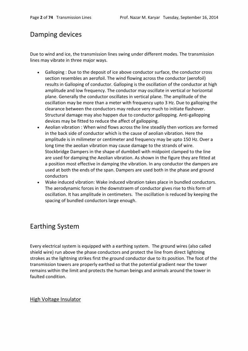
The voltage difference between the phase conductors gives rise to electric field between the conductors ( see Fig-A). The two conductors are just like parallel plates and the air in between the conductors is dielectric. So this arrangement of conductors gives rise to capacitance between the conductors. The value of capacitance depends on the configuration of conductors. We will discuss few configurations and the corresponding capacitance value.
Here in Fig-A is shown the single phase line conductors. In the figure is shown the cross section view of the conductors. See the Electric lines of force representing Electric field. The lines of force start from one conductor and terminate on other. In the diagram it is assumed that there is no other charged body, even the ground (which is at potential zero) is assumed to be far away and has no influence on line capacitance. In this situation,
Let the capacitance between the two lines each of radius r is C Farad per meter of line length. Then,
.k C = ----------- ln(D/r)
Prof. Nazar M. Karyar Tuesday, September 16, 2014 Transmission Lines Page 13 of 74
( ln is for natural logarithm ) k is the permittivity of air. Note: In this article capacitance is always per meter of line length. So the unit is F/m . One important thing is that here the actual radius r is used in the formula. Compare with inductance formula where we used the equivalent radius r' which is 0.7788 times the actual radius r.
In the last article, inductance was found for each line individually. Here also capacitance between line to neutral is desired for per phase analysis of power system. It is important to think that the line to line capacitance is equivalent to two capacitance each of value 2C, one between line-1 and neutral(N) and other between neutral(N) and line-2. See Fig-B. Note: Capacitance in series behaves similar to resistance in parallel. Also capacitance in parallel behaves similar to resistance in series. When two capacitors are connected in parallel their equivalent is sum of the two capacitances.

Prof. Nazar M. Karyar Tuesday, September 16, 2014 Transmission Lines Page 14 of 74
So the line to neutral capacitance Cn is two times C.
Cn = 2 k / ln (D/r)
Now let us consider our favorite case of three phase circuit(see Fig-C) where the phase conductors (a, b and c) occupy the corners of equilateral triangle. The conductors are equidistant from each other. If Cn is the capacitance from line to neutral N (per phase capacitance). Note that point N is imaginary not physical.
Cn = 2 k / ln (D/r)

Prof. Nazar M. Karyar Tuesday, September 16, 2014 Transmission Lines Page 15 of 74
The general form (Fig-D) of capacitance between one phase and neutral for a three phase line is
Cn = 2 k / ln (GMD/GMR)
GMD is Geometric Mean Distance and GMR is Geometric Mean Radius of the particular configuration. GMR used for calculation of capacitance is slightly different from GMR used for inductance as mentioned below. It is also assumed that the phase lines are transposed In actual practice in most of the cases you will find that the three phase conductors are arranged horizontally or nearly vertically as per the tower design. Only in few situations you will find the conductors are placed nearly equidistant from each other. Hence calculation of GMD and GMR are important.
Here in Fig-D the three phase conductors are arbitrarily placed. Let the distance between the phase conductors are D12, D23 and D31 . The distances are between the centers of bundled twin conductors. Similar to inductance, transposing the conductors the capacitance between any two phases is made equal. Or the capacitance between any phase and neutral point are made same. The above equation is actually derived considering transposed lines.
here, GMD = ∛(D12 D23 D31)
In fig-D ACSR twin bundled conductors are used for which GMR is calculated as below.
In case of bundled conductors, the GMR for commonly used bundles are as below
Prof. Nazar M. Karyar Tuesday, September 16, 2014 Transmission Lines Page 16 of 74
For twin conductor bundle
GMR=[(r.d)(r.d)]1/4
= √(r . d)
For triple conductor bundle
GMR=[(r . d . d)(r . d . d)(r . d . d)]1/9
= ∛(r.d2)
For quad conductor bundle
GMR = 1.09 ∜(r.d3)
Note: In case of inductance r' is used. But here the actual radius r is used in GMR calculation In all the above formulas r is the actual radius of circular conductor. But usually ACSR conductors are used. For ACSR conductor in place of r put the value of Ds as supplied by the manufacturer. In Fig-D two ACSR conductors per bundle(twin) are used in each phase a, b and c.
So for Fig-D, GMR =√(r . d)
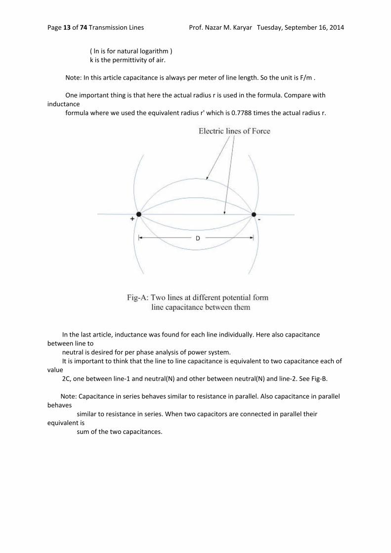
In Fig-E is shown a three phase line (in power sector a three phase line is usually simply called as single circuit line. If the tower is carrying two numbers of such three phase lines then it is called double circuit line). The line is assumed as transposed. Here each phase conductor is comprised of four numbers of conductors(quad conductor). The conductors within a bundle are arranged in a square of side d.
Here,
GMD = ∛(D . D . 2D)
GMR = 1.09 ∜(r.d3)
As already said If ACSR stranded conductors are used (instead of circular one as shown) so Ds as per the manufacturer's data is used in place of r. Ds is the equivalent radius of stranded conductor. The values of GMD and GMR are put on the above equation to find line to neutral capacitance.

Prof. Nazar M. Karyar Tuesday, September 16, 2014 Transmission Lines Page 17 of 74
So far we only considered one three phase circuit (single circuit). An example of double circuit will be considered exclusively in next article for both inductance and capacitance calculation.
Earth being at zero potential influences the electric field. Some electric lines of force originating from conductors terminate on earth surface at 90 degrees. The presence of earth is tackled by considering imaginary image conductors placed below the earth, just like image of real conductors. However the influence of earth on the capacitance of line is small in comparison to the line to line capacitance. So the influence of earth is neglected in many cases. We discuss it here. When the line parameters for all the three phase conductors are nearly equal, then the line voltages at the other end of the line are more or less balanced. Of course the balanced three phase system can be solved by considering any one phase and neutral. This is called per phase analysis. It should be remembered that here neutral does not mean the requirement of a neutral conductor for transmission. Although the above general formula for capacitance derived considering transposed lines, but it is often used for non-transposed lines to get approximate values Labels: Power System
Transmission Line Model: Short and Medium lines
In last few articles we discussed some basic design aspects of electric transmission lines. Sometimes the discussion about a certain part was very brief considering that the same can be elaborated more somewhere else. Effort is made to flash the important points or parts of the subject. In the previous 3/4 articles we developed some concepts on AC transmission line parameters and discussed how the line parameters can be calculated under different configuration of phase conductors. The behavior of transmission lines and its voltage and current under normal and abnormal conditions depends on these parameters. For carrying out system studies the proper modelling of transmission lines is very important. Here in this article we discuss the transmission line modeling . Transmission lines are also called as power lines. Transmission line theory is important for both power and electronics or communication engineering. But here our discussion is mainly from the power engineering point of view. The transmission lines are mainly classified as short, medium or long lines. The classification is based upon the accuracy of the model and simplicity. While the short line model is quite simple, the long line model is somewhat complex and the medium line is in-between the two. At power frequency of 60 or 50 Hz, the lines of length below 80 km are treated as short lines and the length of line exceeding 80 km but less than 250 km can be modeled as medium lines and as the length of lines exceed 250 km it is long line. For short and medium length lines the parameters are lumped. This simplifies the model and gives quite accurate result. In case of the long transmission lines the line parameters are considered as distributed along the length of the line. The aim of the transmission line model is that it should be simple and the analysis of the model should bear desired accuracy. Of course you can apply the long

Prof. Nazar M. Karyar Tuesday, September 16, 2014 Transmission Lines Page 18 of 74
line theory for power lines of length below 80 km. Doing so one can achieve somewhat more accurate result (which may not be desired) while making the model or calculation more complex. Here in this article we will discuss short and medium length lines only and long line is the topic of the next article. Before proceeding further, as we already discussed in our previous articles there are four line parameters, these are line resistance R , inductance L, leakage conductance G and line to neutral capacitance C per meter length of line. Here instead of using the symbol Cn as the capacitance between line and neutral we will adopt C. Here we will use these. z = Series impedance per meter length = R + j ωL Ω / meter (ω = 2 π f where f is the frequency) y = Shunt admittance per meter length = G + j ωC S / meter Ω symbol is for Ohm, the unit of impedance S symbol is for siemens, the unit of admittance. mho or inverted Ohm symbol is also used for admittance As already discussed in our previous article G arises due to leakage currents and is ignored in transmission line modelling.
so, y = j ωC S / meter
If, Z is the total lumped line impedance and Y is the total admittance between the line and neutral, then we get Z and Y by multiplying per meter values with the total length of the line. Then
Z = z .l Ω Y = y .l S
where l is the total length of the line in meter.
Short Lines
As already said the lines of below 80 km length can be modeled as short lines. The transmission line is a three phase system and here assumed as balanced due to transposition and balanced load at receiving end. The analysis adopted here can be applied to unbalanced non-transposed systems for obtaining result with reasonable accuracy. For the balanced three phase line we are only required to analyze one phase. The return path is imaginary neutral. In Fig-A is shown a short transmission line. The resistance and inductance are lumped together which is the transmission line serie impedance Z. Further for short line here the capacitance of the line is ignored so the admittance is ignored.

Prof. Nazar M. Karyar Tuesday, September 16, 2014 Transmission Lines Page 19 of 74
As shown the sending end and receiving end voltages are Vs and Vr respectively and the sending end and receiving end currents are Is and Ir respectively. From the diagram it is clear that both sending and receiving end current are the same Is = Ir According to Kirchhoff's voltage law, Vs = Vr + Z Ir Z = R + j XL R is the total line resistance and XL is the total line inductance, both are lumped. Those who are familiar with two port network analysis, the above can be represented in terms of ABCD parameters. In this form the supply side voltage and current is represented in terms of receving side voltage and current as below Vs = A Vr + B Ir Is = C Vr + D Ir In the above formulas A and D are dimension less. Dimension of B is Ohm and that of C is Siemens. The parameters satisfy the condition AD-BC =1 In transmission line problem this representation is sometimes found suitable. Usually the receiving side voltage and current requirement are given and it is required to find the supply side voltage and current. For the above short line equations we get A = 1, B=Z, C=0, D=1 clearly it satisfies the condition AD-BC=1 Voltage Regulation The performance of a transmission line is determined by a term called voltage regulation. Voltage regulation is defined as the percentage change in voltage at the receiving end from No load to Full load with sending end voltage held constant.

Prof. Nazar M. Karyar Tuesday, September 16, 2014 Transmission Lines Page 20 of 74
or means the values or magnitudes of voltages without sign . So the subtraction is the simple subtraction and not the phasor subtraction. The voltage regulation is desired to be small or zero. Integrated Grids has set standards for voltage variation say ±5% or ±7% depending on voltage levels. The relationship Vs = Vr + Z Ir between the sending end and receiving end voltages can also be illustrated by a phasor diagram shown in Fig-B. In Fig-B(i) we have considered an inductive load. So the receiving end current Ir lags the receiving end voltage Vr by a phase angle φ(determined by load). In Fig-B(ii) is considered a capacitive load. Here current Ir leads the voltage Vr by an angle φ.
In both the diagrams Vr and Z Ir are added as per the rule of phasor addition. Z is the line impedance as discussed above. Z Ir = (R+j XL ) Ir = R Ir +j XL Ir The main difference between the above two is that in case of lagging load the receiving end voltage is less than the sending end voltage. But in case of leading load the receiving end voltage can even become more than the sending end voltage depending on the lead phase angle φ . Which is due to the fact that the load is capacitive. In our case Fig-B (ii), for the chosen phase angle the receiving end voltage is more than the sending end voltage. Actually the industrial loads are mostly inductive. The inductive loads consume reactive power. Capacitors which generate reactive power are connected at the load end or at substations to supply reactive power. At sub-transmission and distribution levels where voltage drop is a problem, capacitors can improve the voltage profile and power factor at the receiving end. The capacitive load helps in improving the receiving end voltage regulation and power factor. For only voltage regulation purpose usually tap changer of transformer is utilized. By tap changing the transformer turns ratio is changed, so adjusting the secondary voltage.

Prof. Nazar M. Karyar Tuesday, September 16, 2014 Transmission Lines Page 21 of 74
Another common definition which sometimes may be useful for evaluation of transmission line performance is the transmission efficiency of the line. The transmission efficiency is defined as the ratio of power delivered at receiving end to the power supplied at sending end. If η is the transmission efficiency then,
cos φ is the power factor at the receiving end, or power factor of load but cos φs is the power factor at the sending end (due to both load and transmission line). Using the above formula it is easy to find the transmission efficiency of short and medium lines. For short line the angle φs is clearly visible from the phasor diagram (angle between Vs and Is (or Ir)). But in case of medium line little more effort is required.
Medium Lines
The medium length lines are categorized as transmission lines of more than 80 km and less than 250 km length. The medium length lines can be modeled two ways. These are nominal π and nomial T (Fig-C), so named due to the arrangement of elements. Due to the length of the line admittance Y is no more neglected. Of course in both the π and nomial T representations lumped elements are used. In the nominal π representation the total admittance due to line capacitance is equally divided into two halves and each half connected at both sending and receiving ends. In the nominal T representation the admittance is connected at the center of line and line impedance is divided into two equal parts and each part is connected on both sides in series (Fig-C).

Prof. Nazar M. Karyar Tuesday, September 16, 2014 Transmission Lines Page 22 of 74
It can be shown that for the π representation the sending end voltage and current can be written in terms of receiving end voltage and current as shown below.
From above two expressions ABCD parameters can be easily identified. Also you should verify the condition AD-BC=1. For T representation also applying KCL and KVL we can obtain the similar expression for Vs and Is. At no load putting Ir = 0 we obtain Vr NL = Vs / A, .
Analysis of short and medium lines helps us gain important concepts of transmission lines. It is useful for long line analysis. 15 comments Links to this post Labels: Power System
Influence of Earth on Capacitance Calculation
In last article we discussed the technique for calculation of inductance and capacitance of double circuit transmission line, which can be easily applied for multi circuit lines. Of course before proceeding further I strongly recommend to go through those articles. I also advise to have a look at the two articles on calculation of line inductance and capacitance in general. Moreover as this article uses basic formulas of logarithm so we have tabulated few useful formulas at the bottom. In the above three articles we developed some basic concepts. In the previous articles we neglected the influence of earth on capacitance calculation of transmission lines. But this is not true for Extra High voltage (EHV) and Ultra High Voltage (UHV) lines. For example for transmission lines above 200 kV voltage level the clearance distance between phases is quite comparable with the clearance between phase and ground. And electric field is considerably influenced by the presence of earth. This situation requires the consideration of influence of earth on calculation of line capacitance.

Prof. Nazar M. Karyar Tuesday, September 16, 2014 Transmission Lines Page 23 of 74
Here I will derive the formulas for calculation of transmission line capacitance. Let us consider a charged line of circular cross section conductor as shown in Fig A. When this object is far removed from earth its electric field will be as shown in Fig-A(i), radial lines of force. In Fig-A(ii) is shown how the electric field is disturbed in the presence of Earth. This field pattern above ground can be obtained by replacing the ground and placing an imaginary oppositely charged similar conductor same distance below the ground line. Here it is imagined that the ground level as a mirror. This is called image charge (see Fig-A (iii)). Now the problem is reduced to a pair of opposite charges.
Let us consider Fig-B where there are two very long line conductors of charge +q and -q coulmb per meter length of the conductor. From the basics it can be shown that the potential at a point P is vp Then,

Prof. Nazar M. Karyar Tuesday, September 16, 2014 Transmission Lines Page 24 of 74
The above equation can also be written as
The above equation can be imagined as the potential ( vp) at the point ' p ' is composed of two components one due to positive charge +q and other due to negative charge -q. These two are respectively first and second terms in the above equation. Generalizing it we can say that the total potential at a point p due to several charges is equal to the sum of the potential due to all the individual charges. Here next we will consider our favorite and practical case of the three phase line. Let us assume that the three phase conductors are placed in a general arbitrary form as shown in Fig -C. Now imagining the ground level as mirror we get the image charges which are -ve of actual charges on conductors as shown. Now the ground line can be removed. In the figure all the distances between the conductors and/or image are illustrated.

Prof. Nazar M. Karyar Tuesday, September 16, 2014 Transmission Lines Page 25 of 74
As illustrated in above case we will obtain the voltage difference between the conductors a and its image a' . For this we have to find the potential at the surface of a and a'. Let the potential at a is va and the potential at a' is va
'. As already said the potential at the surface of conductor a is the simple algebraic sum of the potential due to charges on all the conductors including this particular conductor a. Similarly we can find the potential at the surface of a'. This way we get, Now Vaa' = va-va
' So from the above two equations Or in compact form we can write as

Prof. Nazar M. Karyar Tuesday, September 16, 2014 Transmission Lines Page 26 of 74
As already said the phase conductors are transposed. So for ⅓ rd of distance the conductor of phase-a will take the position of phase-b and conductor of phase-b will take that of c . So for all the three positions we will calculate the voltage for ' a ' phase and take the average. As already said in last articles by transposition, the capacitance between any of the three conductors and neutral
are made equal. If C denotes capacitance then after transposition we get Of course here we will concentrate on calculation of capacitance (Can) between phase-a and neutral. Due to transposition when the phase a conductors will take position of b as shown above and of course b will take position of c and c will take that of a. (You can think cyclically).
Similarly when phase-a conductor occupies the other position .
Let us call the average voltage between conductor a and image conductor a' be va-a'
Then,
Combining above three we get the value of va-a'
But we require the voltage from neutral (n) to phase-a conductor (see Fig-D), that is van
From Fig-D it is clear that,

Prof. Nazar M. Karyar Tuesday, September 16, 2014 Transmission Lines Page 27 of 74
Hence we get
Simplifying we get
or,
but the charges of three phases sum up to zero, So,
by rearranging the terms (see the properties of logarithm below at the end) we finally get
We know that the capacitance between phase a and neutral Can is,
So finally we get
From the above derived formula of capacitance Can we observe that due to the consideration of influence of earth the denominator second term comes into picture and the capacitance Can is more than what we would have got if earth influence was ignored. Logarithm Formulas Table
Prof. Nazar M. Karyar Tuesday, September 16, 2014 Transmission Lines Page 28 of 74
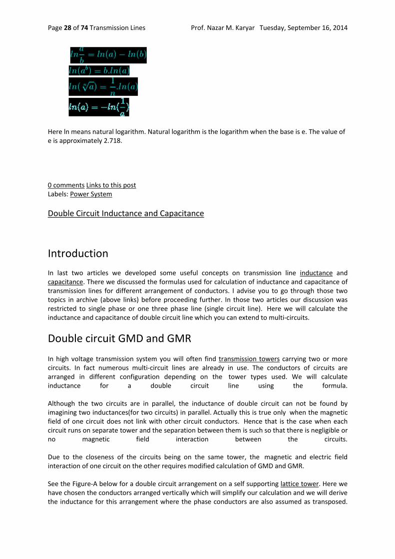
Here ln means natural logarithm. Natural logarithm is the logarithm when the base is e. The value of e is approximately 2.718.
0 comments Links to this post Labels: Power System
Double Circuit Inductance and Capacitance
Introduction
In last two articles we developed some useful concepts on transmission line inductance and capacitance. There we discussed the formulas used for calculation of inductance and capacitance of transmission lines for different arrangement of conductors. I advise you to go through those two topics in archive (above links) before proceeding further. In those two articles our discussion was restricted to single phase or one three phase line (single circuit line). Here we will calculate the inductance and capacitance of double circuit line which you can extend to multi-circuits.
Double circuit GMD and GMR
In high voltage transmission system you will often find transmission towers carrying two or more circuits. In fact numerous multi-circuit lines are already in use. The conductors of circuits are arranged in different configuration depending on the tower types used. We will calculate inductance for a double circuit line using the formula. Although the two circuits are in parallel, the inductance of double circuit can not be found by imagining two inductances(for two circuits) in parallel. Actually this is true only when the magnetic field of one circuit does not link with other circuit conductors. Hence that is the case when each circuit runs on separate tower and the separation between them is such so that there is negligible or no magnetic field interaction between the circuits. Due to the closeness of the circuits being on the same tower, the magnetic and electric field interaction of one circuit on the other requires modified calculation of GMD and GMR. See the Figure-A below for a double circuit arrangement on a self supporting lattice tower. Here we have chosen the conductors arranged vertically which will simplify our calculation and we will derive the inductance for this arrangement where the phase conductors are also assumed as transposed.

Prof. Nazar M. Karyar Tuesday, September 16, 2014 Transmission Lines Page 29 of 74
As we discuss the topic you will realize that the method can be applied to other arrangements or multi-circuits also.
In the figure one circuit phase conductors are a-b-c and other circuit phase conductors are a'-b'-c'. As shown here the phase conductors are single rounded conductors. In the last two articles we have already discussed bundled conductors for inductance and capacitance calculation. Here the double circuit is treated very similar to single circuit or a three phase line with bundled conductors. The conductors a-a' are imagined as bundle conductor for phase A, similarly b-b' and c-c' are imagined as bundle conductors for phases B and C. Of course here the bundle sub-conductors are far away and not bunched unlike the case of twin, triple or quad conductors bundles.

Prof. Nazar M. Karyar Tuesday, September 16, 2014 Transmission Lines Page 30 of 74
Now we are ready to apply the general formula for calculating Geometric Mean Distance(GMD). For calculating GMD all the distances between the phase conductors are identified. In Fig-A(ii) all the distances between the phases are shown. For example a-b, a-c, a-c', a-b', c-b', c-a' etc.. There are 12 possible distances between conductors of phases as shown. It should be noted that for calculation of GMD the distances a-a', b-b' and c-c' are not taken. GMD = (Dab . Dab' . Dbc . Dbc' . Dca . Dca' . Da'b . Da'b' . Db'c . Db'c' . Dc'a . Dc'a')1/12 Clearly there are 12 distances and so 12th root of the product of twelve distances are taken. By rearranging the terms you can also write GMD as below.
GMD = (DAB . DBC . DCA.)1/3
Where DAB = (Dab . Dab' . Da'b . Da'b')1/4 similarly DBC and DCA.
In our example
GMD = (6 . 10 . 6 . 10 . 12 . 8 . 10 . 6 . 10 . 6 . 8 . 12)1/12
meter
= 8.37 meter.
Now let us calculate the Geometric Mean Radius (GMR) For GMR calculation the method is just similar to bundle conductors. Of course for inductance calculation we require r' and for capacitance r. As already said in previous articles the equivalent radius r' =0.7788r . Here let us first calculate the GMR of each phase separately for inductance.
GMRa = √(Daa' . r')
GMRb = √(Dbb' . r')
GMRc = √(Dcc' . r')
Daa' is the distance between the conductors a and a'. Similarly for Dbb' and Dcc' As the phases are transposed so,
GMRL = (GMRa . GMRb . GMRc)1/3
Note: Daa' Dbb' and Dcc' were not used in GMD calculation but used in GMRL calculation. Subscript L is used for GMR of inductance calculation and subscript C for capacitance.
Prof. Nazar M. Karyar Tuesday, September 16, 2014 Transmission Lines Page 31 of 74
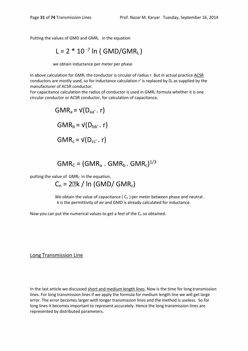
Putting the values of GMD and GMRL in the equation
L = 2 * 10 -7 ln ( GMD/GMRL )
we obtain inductance per meter per phase In above calculation for GMRL the conductor is circular of radius r. But in actual practice ACSR conductors are mostly used, so for inductance calculation r' is replaced by Ds as supplied by the manufacturer of ACSR conductor. For capacitance calculation the radius of conductor is used in GMRC formula whether it is one circular conductor or ACSR conductor, for calculation of capacitance,
GMRa = √(Daa' . r)
GMRb = √(Dbb' . r)
GMRc = √(Dcc' . r)
GMRC = (GMRa . GMRb . GMRc)1/3
putting the value of GMRC in the equation,
Cn = 2 k / ln (GMD/ GMRc) We obtain the value of capacitance ( Cn ) per meter between phase and neutral . k is the permittivity of air and GMD is already calculated for inductance. Now you can put the numerical values to get a feel of the Cn so obtained.
Long Transmission Line
In the last article we discussed short and medium length lines. Now is the time for long transmission lines. For long transmission lines if we apply the formula for medium length line we will get large error. The error becomes larger with longer transmission lines and the method is useless. So for long lines it becomes important to represent accurately. Hence the long transmission lines are represented by distributed parameters.

Prof. Nazar M. Karyar Tuesday, September 16, 2014 Transmission Lines Page 32 of 74
Long Line Model For medium length line we lumped the line impedance at one place. This line impedance which is actually distributed throughout the length of line will be represented here as distributed. The capacitive current between the line conductors flows throughout the length of line. Which necessitates for distributing the line to line capacitance throughout the length of the line. But for a balanced three phase system we analyse per phase analysis. Which necessitates for consideration of phase to neutral capacitance, Both line inductance and capacitance for several configurations are illustrated in previous articles. The equivalent long line representation is shown in Fig-A.
In the diagram the distributed capacitance also automatically requires that the line impedance also distributed. It should be clear from the above figure that in general throughout the length of the line the voltage and current values may vary.
What is the voltage and current at a distance x from the receiving end. See Fig-B Let the voltage and current at a distance x from receiving end are V(x) and I(x) respectively. It should be noted that V(x) and I(x) are phasors.

Prof. Nazar M. Karyar Tuesday, September 16, 2014 Transmission Lines Page 33 of 74
Let Zc = √(Z/Y) and γ =√(ZY) As Z and Y are complex numbers so in general Zc and γ are complex numbers. Zc is called the characteristics impedance and γ is the propagation constant. Zc is commonly called surge impedance in power sector. Formula for calculation of Z and Y are already discussed in previous articles. Z is the series impedance per unit length ( impedance per kilometer or meter) Y is the shunt Admittance per unit length Using differential calculus and solving the resulting differential equations it can be shown that,
The above formula can be rearranged and written in several ways. Rearranging the terms and using the formulas of complex hyperbolic, the above formulas for V(x) and I(x) can be written in the form

Prof. Nazar M. Karyar Tuesday, September 16, 2014 Transmission Lines Page 34 of 74
To find the voltage Vs and current Is at the sending end, we just have to put l (length of line) in place of x in the above formulas. So at the sending end
If you compare the above equations relating sending and receiving end voltage and current with the corresponding equations discussed in last article for medium length lines then we can easily find ABCD parameters. These are
You can argue that the long transmission line can also be represented by a nominal ∏ circuit. Yes a long line can be represented by an equivalent ∏ circuit. It should be remembered that in case of medium length line it is called Nominal ∏. Here it is called equivalent ∏. This equivalent ∏ is only a convient representation of the actual long line analysis. But Nominal ∏ is an approximation for medium lines. For load flow study and other system studies this equivalent representation is very helpful without sacrificing any accuracy. In Fig-C is shown the equivalent ∏ representation of any line of length l according to long line theory.
It is left as an exercise for you to find Z' and Y' by comparing with Medium length line.
Surge Impedance loading

Prof. Nazar M. Karyar Tuesday, September 16, 2014 Transmission Lines Page 35 of 74
In all the above formulas we used two parameters Zc and γ. These two parameters are very important. Of course these two parameters are derived from our transmission line parameters Z and Y. The characteristics of the long line depends upon these two parameters. As already said Zc and γ are complex numbers. Let us consider a case when the load impedance is just equal to the characteristics impedance Zc
then, the receiving end voltage Vr =Ir Zc substituting in above equations we get
and
let, γ = α+j β Dividing V(x) by I(x) we get
From the above equation it is easy to interpret that the impedance as seen at any point of the line is the same as the load impedance that is Zc , the characteristics impedance. Moreover from the above equations of V(x) and I(x) it is clear that
The magnitude of voltage is Clearly the magnitude of the voltage increases with x. But our x increases from receiving end to sending end. So the voltage increases exponentially from receiving end to sending end. At the sending end the voltage is
The other term is the phasor and only provides phase shift between the voltages at receiving end and at a point x distance from the receiving end. Similar argument can be made for equation of
Prof. Nazar M. Karyar Tuesday, September 16, 2014 Transmission Lines Page 36 of 74
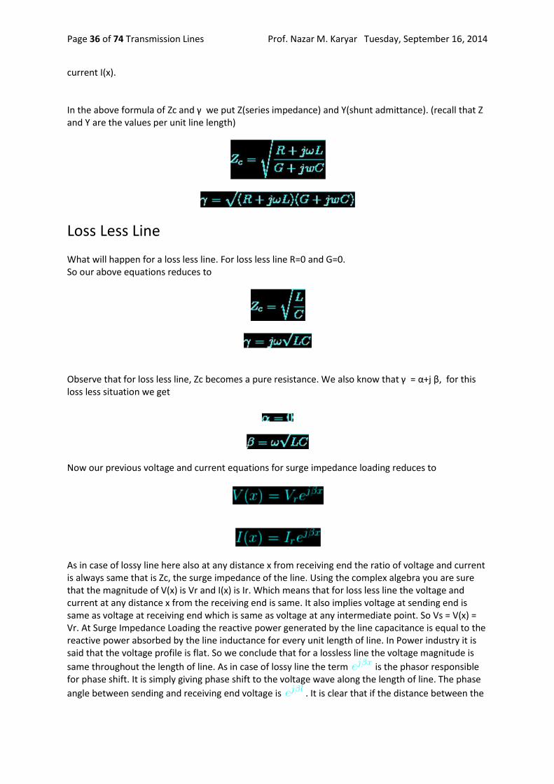
current I(x). In the above formula of Zc and γ we put Z(series impedance) and Y(shunt admittance). (recall that Z and Y are the values per unit line length)
Loss Less Line
What will happen for a loss less line. For loss less line R=0 and G=0. So our above equations reduces to
Observe that for loss less line, Zc becomes a pure resistance. We also know that γ = α+j β, for this loss less situation we get
Now our previous voltage and current equations for surge impedance loading reduces to
As in case of lossy line here also at any distance x from receiving end the ratio of voltage and current is always same that is Zc, the surge impedance of the line. Using the complex algebra you are sure that the magnitude of V(x) is Vr and I(x) is Ir. Which means that for loss less line the voltage and current at any distance x from the receiving end is same. It also implies voltage at sending end is same as voltage at receiving end which is same as voltage at any intermediate point. So Vs = V(x) = Vr. At Surge Impedance Loading the reactive power generated by the line capacitance is equal to the reactive power absorbed by the line inductance for every unit length of line. In Power industry it is said that the voltage profile is flat. So we conclude that for a lossless line the voltage magnitude is
same throughout the length of line. As in case of lossy line the term is the phasor responsible for phase shift. It is simply giving phase shift to the voltage wave along the length of line. The phase
angle between sending and receiving end voltage is . It is clear that if the distance between the

Prof. Nazar M. Karyar Tuesday, September 16, 2014 Transmission Lines Page 37 of 74
sending and receiving end is more then the phase difference between the voltage phasors at both the ends of the line will be more. In previous articles we already discussed that in case of transmission line how and when we can ignore the line resistance R and leakage conductance G. At least for rough estimate of the load carrying capability of transmission line we can presume it lossless. The surge impedance loading is the ideal loading of the line, which is desired keeping in view of the optimised (flat for lossless ideal case) voltage profile of the line. For Loss less line the surge impedance loading (SIL) is
Where
It should be recalled that Zc is pure resistance for lossless line. Vr and Vl are the receiving end phase and line voltage respectively. Approximate SIL for few nominal voltages
132/138 kV - 50 MW 230 kV - 150 MW 345 kV - 400 MW 400 kV - 500 MW 500 kV - 900 MW 765 kV - 2090 MW
Above values of SIL is true for both 50 Hz and 60 Hz systems.
Line Loadability
System planners usually use line loadabilty curve for deciding loading capability of the line. See Fig-D. The relationship between SIL and length in km shown in Fig-D is almost same for all voltage levels.

Prof. Nazar M. Karyar Tuesday, September 16, 2014 Transmission Lines Page 38 of 74
What is the capacity of the transmission line or how much power it can carry. The power that a transmission line can carry are based on three factors. These are
Thermal Limit Voltage Drop Limit Stability Limit
Due to the current flow heat is generated in the line and the line length changes which gives rise to more sag. Sometimes heating of the line is enough that, later cooling of the line due to less load or environment factors does not make the line regain its actual length. The sagging become permanent. Due to this the minimum clearance of the line to ground decreases which may violates the standard set by the local authority. Also if the load is very high the conductor may be damaged due to excessive heat. All transmission lines has thermal limits. But the thing is that only short lines can approach this limit. Voltage drop and stability limits situation usually do not arise here due to short length. Lines less than 80 km length falls in this category. For medium length line the loading is mainly limited by allowable voltage drop (usually between 5 to 10 % as set in grid standard). For medium length line the steady state stability limit situation usually does not arises due to lesser length(discussed below). But the length is enough so that the medium length line can encounter the voltage drop limit before reaching thermal limit. By reactive compensation the voltage drop limit can be increased. Lines exceeding 80 km and less than 250 km long belong to this category. For long line(above 250 km) we have shown that effort is made to operate the line with surge impedance loading. So for long lines the voltage profile may be made more or less flat with SIL loading. If the loading of line exceeds above SIL then the voltage at receiving end is less than sending end. If the loading of the line is less than SIL then the voltage at receiving end is more than sending end. This phenomenon is called Ferranti effect. For very lightly loaded or open long lines the
Prof. Nazar M. Karyar Tuesday, September 16, 2014 Transmission Lines Page 39 of 74
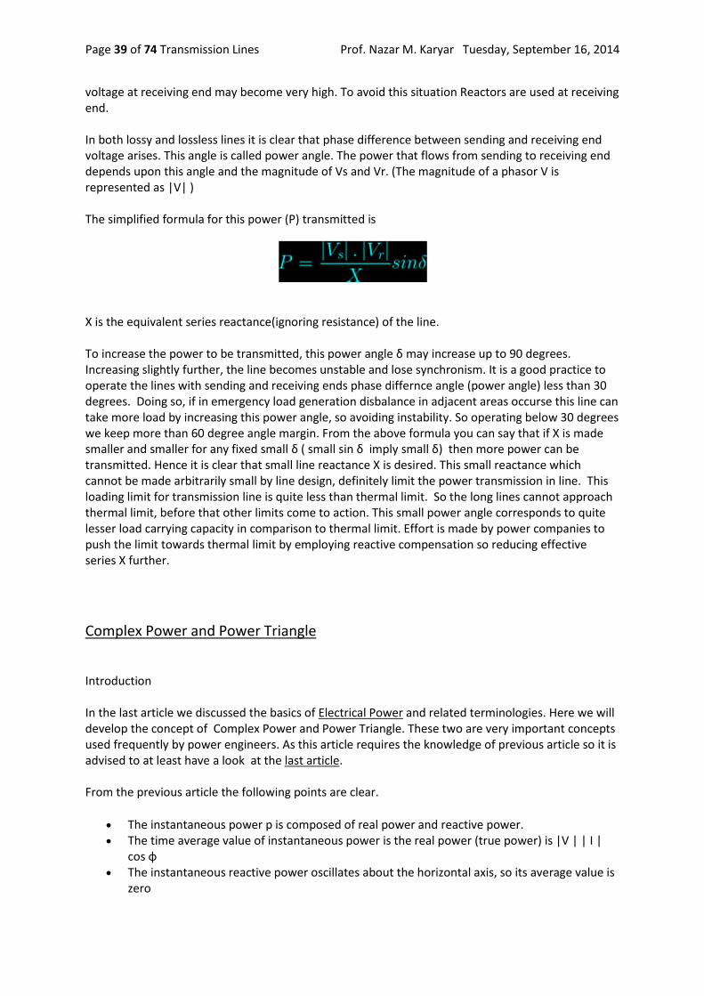
voltage at receiving end may become very high. To avoid this situation Reactors are used at receiving end. In both lossy and lossless lines it is clear that phase difference between sending and receiving end voltage arises. This angle is called power angle. The power that flows from sending to receiving end depends upon this angle and the magnitude of Vs and Vr. (The magnitude of a phasor V is represented as |V| ) The simplified formula for this power (P) transmitted is
X is the equivalent series reactance(ignoring resistance) of the line. To increase the power to be transmitted, this power angle δ may increase up to 90 degrees. Increasing slightly further, the line becomes unstable and lose synchronism. It is a good practice to operate the lines with sending and receiving ends phase differnce angle (power angle) less than 30 degrees. Doing so, if in emergency load generation disbalance in adjacent areas occurse this line can take more load by increasing this power angle, so avoiding instability. So operating below 30 degrees we keep more than 60 degree angle margin. From the above formula you can say that if X is made smaller and smaller for any fixed small δ ( small sin δ imply small δ) then more power can be transmitted. Hence it is clear that small line reactance X is desired. This small reactance which cannot be made arbitrarily small by line design, definitely limit the power transmission in line. This loading limit for transmission line is quite less than thermal limit. So the long lines cannot approach thermal limit, before that other limits come to action. This small power angle corresponds to quite lesser load carrying capacity in comparison to thermal limit. Effort is made by power companies to push the limit towards thermal limit by employing reactive compensation so reducing effective series X further.
Complex Power and Power Triangle
Introduction In the last article we discussed the basics of Electrical Power and related terminologies. Here we will develop the concept of Complex Power and Power Triangle. These two are very important concepts used frequently by power engineers. As this article requires the knowledge of previous article so it is advised to at least have a look at the last article. From the previous article the following points are clear.
The instantaneous power p is composed of real power and reactive power. The time average value of instantaneous power is the real power (true power) is |V | | I |
cos φ The instantaneous reactive power oscillates about the horizontal axis, so its average value is
zero
Prof. Nazar M. Karyar Tuesday, September 16, 2014 Transmission Lines Page 40 of 74
The maximum value of the reactive power is |V | | I | sin φ
It should be remembered that real power is the average value and the reactive power is maximum value.
Complex Power
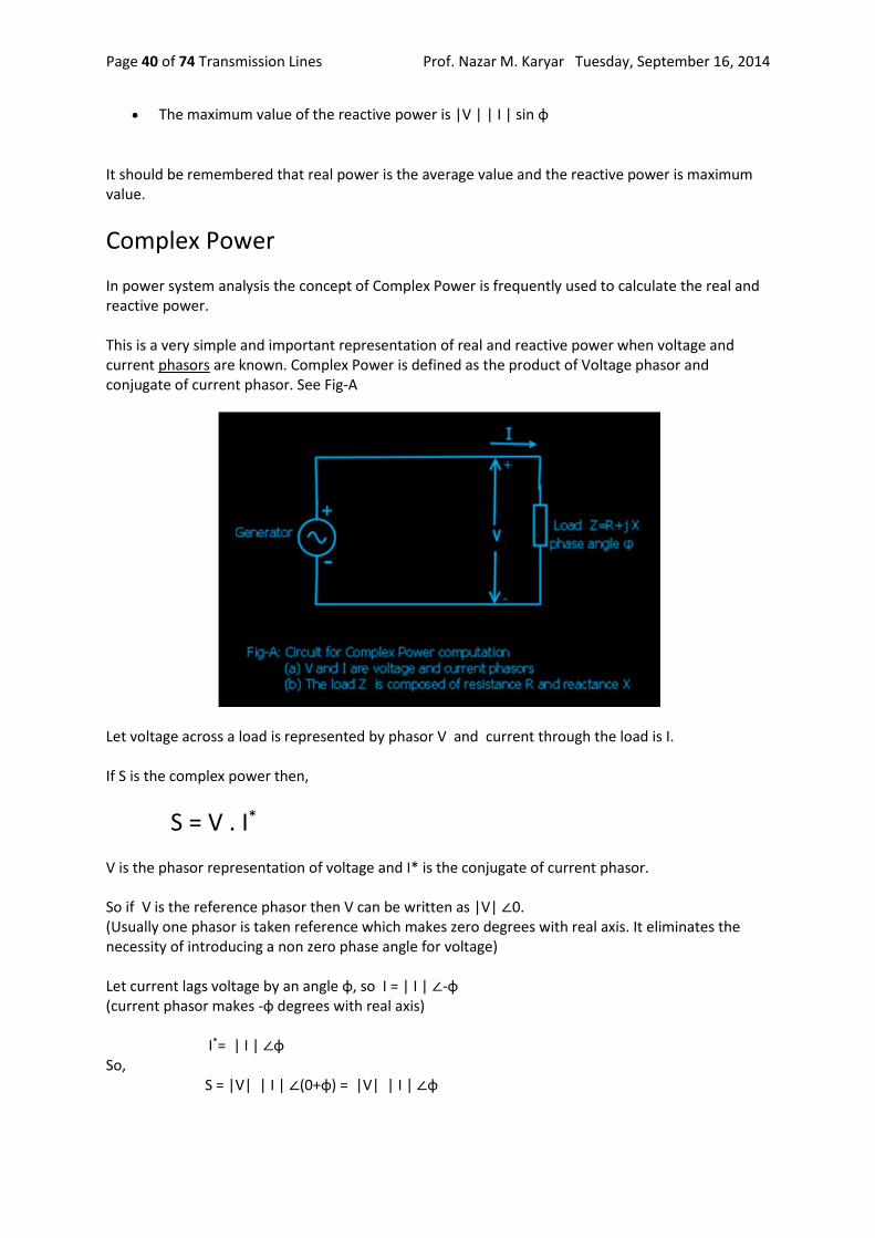
In power system analysis the concept of Complex Power is frequently used to calculate the real and reactive power. This is a very simple and important representation of real and reactive power when voltage and current phasors are known. Complex Power is defined as the product of Voltage phasor and conjugate of current phasor. See Fig-A
Let voltage across a load is represented by phasor V and current through the load is I. If S is the complex power then,
S = V . I*
V is the phasor representation of voltage and I* is the conjugate of current phasor. So if V is the reference phasor then V can be written as |V| ∠0. (Usually one phasor is taken reference which makes zero degrees with real axis. It eliminates the necessity of introducing a non zero phase angle for voltage) Let current lags voltage by an angle φ, so I = | I | ∠-φ (current phasor makes -φ degrees with real axis) I*= | I | ∠φ So, S = |V| | I | ∠(0+φ) = |V| | I | ∠φ

Prof. Nazar M. Karyar Tuesday, September 16, 2014 Transmission Lines Page 41 of 74
(For multiplication of phasors we have considered polar form to facilitate calculation) Writting the above formula for S in rectangular form we get
S = |V| | I | cos φ + j |V| | I | sin φ
The real part of complex power S is |V| | I | cos φ which is the real power or average power and the imaginary part |V| | I | sin φ is the reactive power.
So, S = P + j Q
Where P = |V| | I | cos φ and Q = |V| | I | sin φ
It should be noted that S is considered here as a complex number. The real part P is average power which is the average value, where as imaginary part is reactive power which is a maximum value. So I do not want to discuss further and call S as phasor. If you like more trouble I also advise you to read my article about phasor or some other articles on phasor and complex numbers. Returning to our main point, from the above formula it is sure that P is always more than zero. Q is positive when φ is positive or current lags voltage by φ degrees. This is the case of inductive load. We previously said that inductance and capacitance do not consume power. The power system engineers often say about reactive power consumption and generation. It is said that inductive loads consume reactive power and capacitors produce reactive power. This incorrect terminology creates confusion. The fact is that most of the loads are inductive and they unnecessarily draw more current from source. Although in each cycle both inductance and capacitance draw power from the source and return same amount of power to the source but the behavior of inductance and capacitance are opposing to each other. When capacitors are connected in parallel to inductive load the power requirement of inductive load is supplied by capacitor in half cycle and in next half cycle the reverse happens. Depending upon the values of capacitor this power requirement of inductance in the load may be fully or partially satisfied. If partially satisfied the rest will be drawn from the distant source. By properly selecting the capacitance the maximum value of reactive power (Q) drawn from the distant source (or returned to the distant source) is reduced. This reduction in reactive power results in reduction of line current so the reduction of losses in transmission line and improvement in voltage at load end.
Power Triangle
Returning to the complex power formula, P, Q and S are represented in a power triangle as shown in figure below.

Prof. Nazar M. Karyar Tuesday, September 16, 2014 Transmission Lines Page 42 of 74
S is the hypotenuse of the triangle, known as Apparent Power. The value of apparent power is |V|| I |
or |S| = |V|| I |
It is measured in VoltAmp or VA. P is measured in watt and Q is measured in VoltAmp-Reactive or VAR. In power systems instead of these smaller units larger units like Megawatt, MVAR and MVA is used.
The ratio of real power and apparent power is the power factor of the load.
power factor = Cos φ = |P| / |S|
= |P| / √(P 2+Q 2) The reactive power Q and apparent power S are also important in power system analysis. As just shown above the control of reactive power is important to maintain the voltage within the allowed limits. Apparent power is important for rating the electrical equipment or machines.
Total Power of Parallel Circuits
In real world the loads are usually connected in parallel. Here we will show the total power consumed by parallel branches. See Figure-C. It has two branches.

Prof. Nazar M. Karyar Tuesday, September 16, 2014 Transmission Lines Page 43 of 74
First we have to draw the individual power triangles for each branch. Next the power triangles are arranged back to back keeping real power in positive x direction as shown. The total power consumed is obtained by connecting starting point O to the tip of last triangle. This is actually the result of addition of complex numbers. If S1 = P1 +j Q1 S2 = P2 +j Q2
Then, S = S1+ S2
or S = (P1+ P2 ) + j (Q1+ Q2 ) P = P1+ P2 Q = Q1+ Q2

Prof. Nazar M. Karyar Tuesday, September 16, 2014 Transmission Lines Page 44 of 74
In the above diagram S1 P1 , Q1 and φ 1 correspond to branch1 and S2 P2 , Q2 and φ 2 correspond to branch2. S, P, Q and φ correspond to total power consumption as seen by the generator
0 comments Links to this post Labels: Basics
Instantaneous, Average, Real and Reactive Power
Forward We discussed and developed some important concepts of transmission lines in last few articles. Last time we discussed about long transmission lines. Here we discuss a simple but important basic concept Electric Power. This will refresh our knowledge before we move further. Electric Power has same meaning as mechanical power but here the power or energy that we are concerned is in Electrical form. We often encounter terms like instantaneous, average, total, real, reactive, apparent and complex power or simply power. What they mean? how are they related ? That we will discuss here and in next article.
DC Circuit
As long as our analysis is restricted to Direct Current(DC) circuit the power consumed by the resistance load is the product of voltage across the resistance and current flowing through the resistance. It is really simple. P = V . I
The power consumed by the load is the product of voltage across the load and current drawn by the load (Fig-A). Or the Power supplied by the DC source (battery/cell) is the product of voltage across the cell and current supplied by the cell. Both are equal in our example figure(considering ideal battery of zero internal resistance). The law of energy conservation implies power supplied by the source must be same as power consumed by the circuit. In DC circuit case instantaneous power is same as average power.
AC Circuit

Prof. Nazar M. Karyar Tuesday, September 16, 2014 Transmission Lines Page 45 of 74
In AC circuit analysis, what is this power that we talk about. The main problem is that the AC voltage and current varies sinusoidally with time. Moreover the presence of circuit reactive elements like Inductor and capacitor shift the current wave with respect to voltage wave (angle of phase difference). Power is rate at which energy is consumed by load or produced by generator. Whether it is DC circuit or AC circuit, the value of instantaneous power is obtained by multiplying instantaneous voltage with instantaneous current. If at any instant of time t the voltage and current values are represented by sine functions as v = Vm sin ωt i = Im sin (ωt-φ)
Vm and Im are the maximum values of the sinusoidal voltage and current. Here ω=2 π f f is the frequency and ω is the angular frequency of rotating voltage or current phasors. It should be clear that for a power system f is usually 50 or 60 Hz φ is the phase difference between the voltage and current.
As we said the instantaneous power is the product of instantaneous voltage and current, if we name instantaneous power as p then p = v.i = Vm sin ωt . Im sin (ωt-φ) or p = Vm Im sin ωt sin (ωt-φ) Applying trigonometric formula 2.sin A.sin B = cos(A-B) - cos (A+B) we get
It can be written as
This is the equation of instantaneous power
Prof. Nazar M. Karyar Tuesday, September 16, 2014 Transmission Lines Page 46 of 74
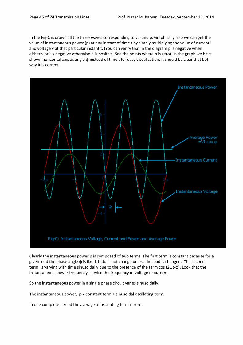
In the Fig-C is drawn all the three waves corresponding to v, i and p. Graphically also we can get the value of instantaneous power (p) at any instant of time t by simply multiplying the value of current i and voltage v at that particular instant t. (You can verify that in the diagram p is negative when either v or i is negative otherwise p is positive. See the points where p is zero). In the graph we have shown horizontal axis as angle φ instead of time t for easy visualization. It should be clear that both way it is correct.
Clearly the instantaneous power p is composed of two terms. The first term is constant because for a given load the phase angle φ is fixed. It does not change unless the load is changed. The second term is varying with time sinusoidally due to the presence of the term cos (2ωt-φ). Look that the instantaneous power frequency is twice the frequency of voltage or current.
So the instantaneous power in a single phase circuit varies sinusoidally. The instantaneous power, p = constant term + sinusoidal oscillating term.
In one complete period the average of oscillating term is zero.
Prof. Nazar M. Karyar Tuesday, September 16, 2014 Transmission Lines Page 47 of 74
Then what is the average power within a given time, say one Time Period of the wave? It is the constant term. Here is another way to think about the average power. Just observe that the instantaneous power is negative for a small time. For any time interval you just find the total +ve area A+ (above horizontal-axis (blue line) and below p curve) and total -ve area A- (below horizontal axis and above p curve). The net area is obtained by subtracting A- from A+. By dividing this net area ( by the time interval Ti we get the average power(P). You can do this using calculus. What you will ultimately get is only the first term in the above formula for instantaneous power p.
In still another way it is easier to realize that the formula for instantaneous power p has a constant term (Vm.Im / 2) cos φ and the other sinusoidal term (Vm.Im / 2) cos (2 wt - φ). Actually p is the oscillating power which oscillates about the average constant term (Vm.Im / 2) cos φ .
So the average power is
The above formula can be written as
Or,
here,
V and I are the phasor representation of RMS values* of voltage and current sinusoids. The symbols |V| and |I| are the magnitudes of phasors V and I. (See at the buttom for definition of RMS value). This above formula is your favorite formula for useful power that we are most concerned about. This average power formula is used to find the power consumed by the load. The monthly electric energy bill at home is based on this power. The engineers and technicians in power or electrical industry simply use the term power instead of average power. So whenever we simply call power it means average power.
Of course the instantaneous power is oscillating in nature. As we already said it does not oscillates about the horizontal-axis rather about the average power P (cyan color horizontal line).
Prof. Nazar M. Karyar Tuesday, September 16, 2014 Transmission Lines Page 48 of 74
P will be zero when cos φ =0 or φ = 90 degree, that is when the phase angle between voltage and current waves is 90 degrees. It is only when the load is pure inductive or capacitive. In this case the second term only remains in the instantaneous power formula. From the above figure for some time the power becomes negative that means the load supply energy to source for this period. This is due to the presence of reactive element in load. The above formula for instantaneous power can be written in another form. This form actually is an attempt to distinguish the oscillating reactive power from the instantaneous power formula. Rearranging the terms in equation for instantaneous power above we get
p = |V| | I | cos φ (1-cow2ωt) - |V| | I | sin φ sin2ωt
In this equation the first term |V| | I | cos φ (1-cow2ωt) is oscillatory whose average value is |V| | I | cos φ. We already talked about this average power. The second term |V| | I | sin φ sin2ωt which is also oscillatory but with zero average value. The maximum value of this term is |V| | I | sin φ. This is the so called Reactive power. So Reactive power is the maximum value of a oscillatory power that is repeatedly drawn from the source and again returned to the source within each cycle. So the average of this reactive power is zero. The average power P is called as Real Power. It is also sometimes called active power.
Real power = P = |V| | I | cos φ
It is usually written as P = VI cos φ. But it should be remembered that V and I are the rms values of voltage and current. For example when we say single phase 220 volt AC it means the rms value of voltage is 220 volts ( it is not maximum value of voltage sinusoid)
Reactive power = Q = |V| | I | sin φ
Real power is measured in Watt and the reactive power is measured in VAR (VoltAmpereReactive). In power sector these units are too small so real power is measured in Megawatt (MW) and reactive power in Megavar (MVAR). The letter R at the end denotes reactive power. Many times students and practicing engineers are confused about the average power (often simply called power). They think that what they get by multiplying RMS voltage and RMS current is RMS power. No that is wrong. There is no RMS power. RMS power has no meaning or not defined. (Also see definition of RMS value, below at the end). It is average power or real power or true power. Power In Three phase Balanced System Let us consider a three phase balanced system. A three phase balanced system is analysed considering only one phase and neutral return. This is called per phase analysis. So the above analysis for single phase is true for balanced three phase case. Let the total power here is Pt. Then we get total three phase power as thrice of single phase case.
Pt = 3 |V| | I | cos φ
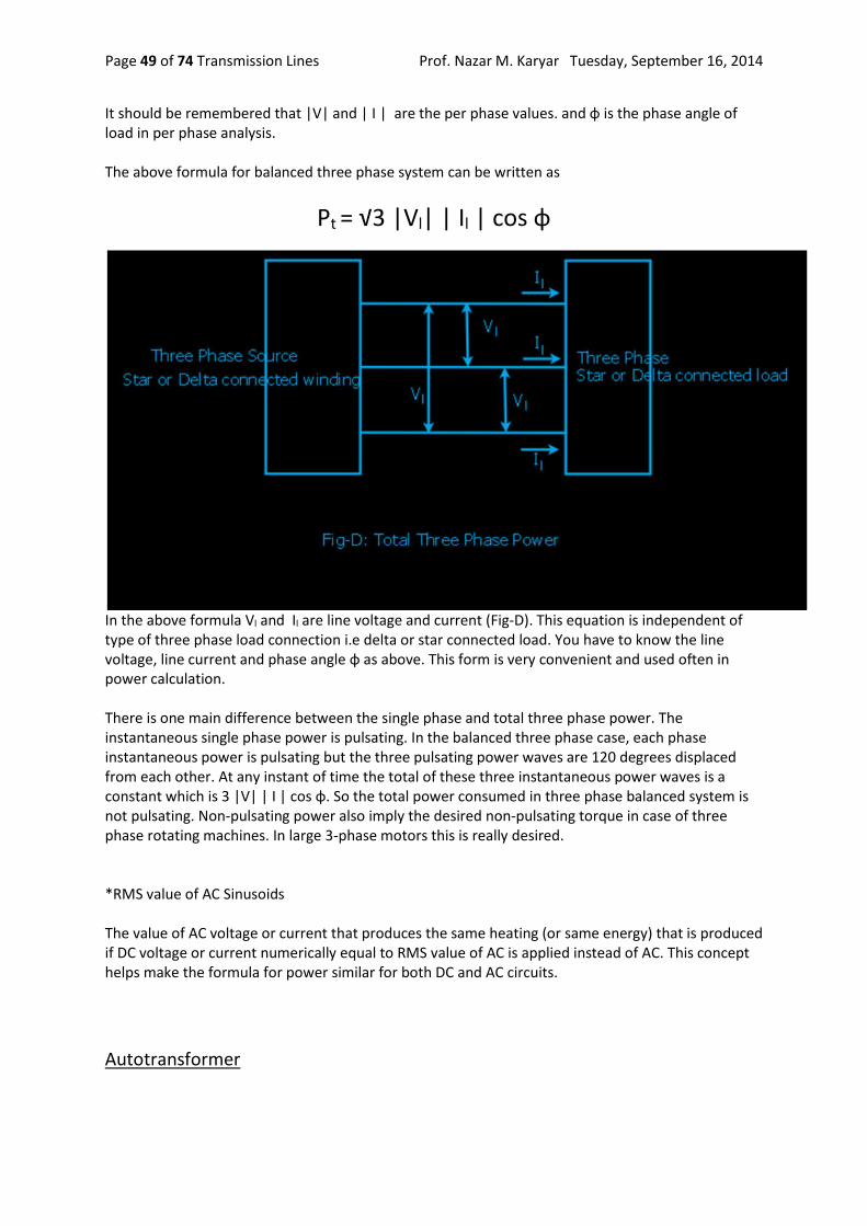
Prof. Nazar M. Karyar Tuesday, September 16, 2014 Transmission Lines Page 49 of 74
It should be remembered that |V| and | I | are the per phase values. and φ is the phase angle of load in per phase analysis. The above formula for balanced three phase system can be written as
Pt = √3 |Vl| | Il | cos φ
In the above formula Vl and Il are line voltage and current (Fig-D). This equation is independent of type of three phase load connection i.e delta or star connected load. You have to know the line voltage, line current and phase angle φ as above. This form is very convenient and used often in power calculation. There is one main difference between the single phase and total three phase power. The instantaneous single phase power is pulsating. In the balanced three phase case, each phase instantaneous power is pulsating but the three pulsating power waves are 120 degrees displaced from each other. At any instant of time the total of these three instantaneous power waves is a constant which is 3 |V| | I | cos φ. So the total power consumed in three phase balanced system is not pulsating. Non-pulsating power also imply the desired non-pulsating torque in case of three phase rotating machines. In large 3-phase motors this is really desired. *RMS value of AC Sinusoids The value of AC voltage or current that produces the same heating (or same energy) that is produced if DC voltage or current numerically equal to RMS value of AC is applied instead of AC. This concept helps make the formula for power similar for both DC and AC circuits.
Autotransformer
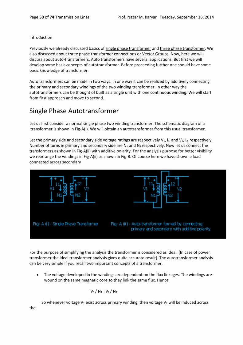
Prof. Nazar M. Karyar Tuesday, September 16, 2014 Transmission Lines Page 50 of 74
Introduction Previously we already discussed basics of single phase transformer and three phase transformer. We also discussed about three phase transformer connections or Vector Groups. Now, here we will discuss about auto-transformers. Auto transformers have several applications. But first we will develop some basic concepts of autotransformer. Before proceeding further one should have some basic knowledge of transformer. Auto transformers can be made in two ways. In one way it can be realized by additively connecting the primary and secondary windings of the two winding transformer. In other way the autotransformers can be thought of built as a single unit with one continuous winding. We will start from first approach and move to second.
Single Phase Autotransformer
Let us first consider a normal single phase two winding transformer. The schematic diagram of a transformer is shown in Fig-A(i). We will obtain an autotransformer from this usual transformer. Let the primary side and secondary side voltage ratings are respectively V1, I1 and V2, I2 respectively. Number of turns in primary and secondary side are N1 and N2 respectively. Now let us connect the transformers as shown in Fig-A(ii) with additive polarity. For the analysis purpose for better visibility we rearrange the windings in Fig-A(ii) as shown in Fig-B. Of course here we have shown a load connected across secondary
For the purpose of simplifying the analysis the transformer is considered as ideal. (In case of power transformer the ideal transformer analysis gives quite accurate result). The autotransformer analysis can be very simple if you recall two important concepts of a transformer.
The voltage developed in the windings are dependent on the flux linkages. The windings are wound on the same magnetic core so they link the same flux. Hence
V1 / N1= V2 / N2 So whenever voltage V1 exist across primary winding, then voltage V2 will be induced across the

Prof. Nazar M. Karyar Tuesday, September 16, 2014 Transmission Lines Page 51 of 74
secondary winding irrespective of changes in connections.
Similarly the magnetic circuit demands that mmf should be balanced. It implies the primary side ampere turn should equal the secondary side ampere turn. Hence
I1 . N1= I2 . N2 It means current I2 that flows in secondary winding is associated with current I1 in primary winding according to above mmf balance formula.
In Fig-B the primary of autotransformer is taken across both the windings where as secondary is across N2 winding. The autotransformer is so loaded that the secondary current is I1+I2 . It makes the current flowing in the windings as I1 and I2 which are the rated values. using KCL and KVL if the primary side voltage and current of the auto transformer is Vp and Ip and secondary side voltage and current of the auto transformer is Vs and Is then, Vp = V1+V2 Ip = I1 Vs = V2 Is = I1+I2. Now the capacity of the autotransformer is (V1+V2).I1 or (I1+I2).V2 Using the voltage ratio and mmf balance formula it is quite easy to show that the autotransformer capacity formula can be simplified as The capacity of autotransformer = Sa = (V1 + V2).I1 = (I1 + I2).V2 = V1 I1 (1 + N2 / N1) = V2 I2 (1 + N2 / N1) Where as the capacity of our original transformer = S =V1 I1 = V2 I2 So, Sa = S(1 + N2 / N1) But (1 + N2 /N1) is always greater than 1.

Prof. Nazar M. Karyar Tuesday, September 16, 2014 Transmission Lines Page 52 of 74
Hence by forming an autotransformer the capacity of the resulting autotransformer is always more than the original isolated winding type transformer. In the so formed autotransformer it should be remembered that the voltage and current through the windings remains as before i.e the rated values. From the above formula it is clear that larger value of N2/N1 gives larger capacity of the autotransformer. In this case the voltage ratio of autotransformer = (V1+V2)/ V2= V1 / V2 +1 = (N1 / N2 ) + 1 Hence Vp / Vs = (N1 / N2 ) +1 = (N1 / N2 ) +1 From this formula it is clear that if N2 /N1 is made large to increase the capacity then the voltage ratio between primary and secondary of autotransformer approaches 1. For this reason auto transformers are advantageous for use in power network when the voltage ratio between both sides is near unity. It is used in grid substations as interconnecting transformers (ICT). The autotransformers are used to interconnect two different voltage levels. For example interconnection of 400kV and 220kV, 735kV and 345kV and 765kV and 400kV etc.. The voltage ratio should be less than 3:1 for more advantageous use. Again look at the formula, I1 . N1= I2 . N2 As we said N2 /N1 should be large for adavantageous use. To achieve it, N2 should be much greater than N1 It implies that I2 will be much less than I1 The current I2 flows in the common winding of the autotransformer. Hence the auto transformer can be designed with N2 number of turns made of conductor of smaller cross section area, so resulting in a big saving.The autotransformers are cheaper and lighter in comparison to two winding transformers. Just looking at the sketch you may think that instead of connecting two windings in additive ways. Why should not it be made of single winding and one terminal brought out from the middle as per requirement. Yes this is true and the autotransformer can be thought of made of a single winding having a part of winding common to primary and secondary . Sometimes this method is used to obtain a variable secondary voltage. This case it is so designed that the middle contact can smoothly slides over the coil. It is commonly used in the academic electrical laboratories. This is usually called as Variac(Fig-C) or Dimmerstat. There are some other terminologies adopted by different manufacturers. In this design it is not possible to adopt conductors of two different cross sectional area as in case of ICT where turns ratio is fixed(due to fixed voltage ratio) between primary and secondary. Autotransformers are also used for voltage regulation in distribution networks, for starting of induction motors and as lighting dimmers. Autotransformers are also used in electric traction.
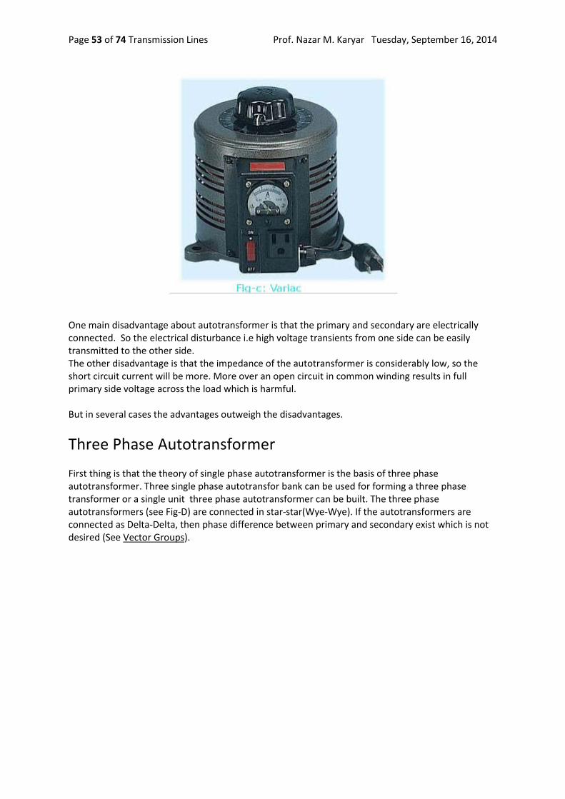
Prof. Nazar M. Karyar Tuesday, September 16, 2014 Transmission Lines Page 53 of 74
One main disadvantage about autotransformer is that the primary and secondary are electrically connected. So the electrical disturbance i.e high voltage transients from one side can be easily transmitted to the other side. The other disadvantage is that the impedance of the autotransformer is considerably low, so the short circuit current will be more. More over an open circuit in common winding results in full primary side voltage across the load which is harmful. But in several cases the advantages outweigh the disadvantages.
Three Phase Autotransformer
First thing is that the theory of single phase autotransformer is the basis of three phase autotransformer. Three single phase autotransfor bank can be used for forming a three phase transformer or a single unit three phase autotransformer can be built. The three phase autotransformers (see Fig-D) are connected in star-star(Wye-Wye). If the autotransformers are connected as Delta-Delta, then phase difference between primary and secondary exist which is not desired (See Vector Groups).

Prof. Nazar M. Karyar Tuesday, September 16, 2014 Transmission Lines Page 54 of 74
In three phase Y-Y connected power autotransformers an additional delta connected winding is used to take care of zero sequence currents (for unbalanced systems), and third harmonic currents. Although we discussed here is for one particular case still we revealed the general approach. If you wish to connect load across the other winding, then you can proceed in a similar way. Moreover the above analysis is for step down case. You can easily analyze for step up case by interchanging the position of source and load. In this case the direction of I1+I2 is reversed so also the directions of I1 and I2. It should be recalled again that the change of direction of current in series winding is associated with change of direction of current in common winding to satisfy mmf balance.
Substation Planning and Siting
We have already discussed in brief about different types of electrical substations. Now we will discuss about the main factors influencing selection of substation. The discussion is mainly for transmission substation which requires many factors to be considered before selecting the site, size etc. The smaller or distribution substation has fewer requirements so only some of the points are required to be considered. A substation is like a junction point in a power system. Many transmission lines at different voltage levels terminate at a substation. Shut down of the substation means shutdown of all the lines terminating at the substation. Clearly a substation is a very important unit of power system. A transmission substation may be comprised of one or more of the following main sections depending on its size and importance. These are Switchyards, Control rooms, Office building and Colony for employees. See the figure at the bottom. The substation planning requires several factors
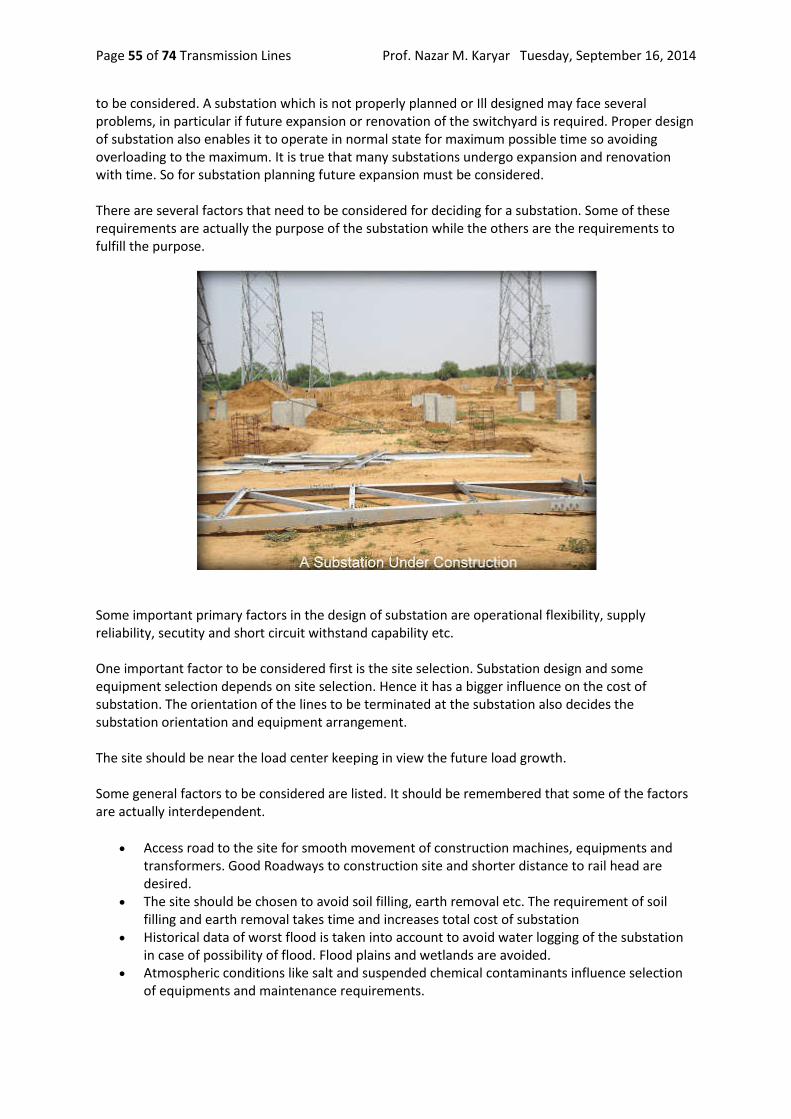
Prof. Nazar M. Karyar Tuesday, September 16, 2014 Transmission Lines Page 55 of 74
to be considered. A substation which is not properly planned or Ill designed may face several problems, in particular if future expansion or renovation of the switchyard is required. Proper design of substation also enables it to operate in normal state for maximum possible time so avoiding overloading to the maximum. It is true that many substations undergo expansion and renovation with time. So for substation planning future expansion must be considered. There are several factors that need to be considered for deciding for a substation. Some of these requirements are actually the purpose of the substation while the others are the requirements to fulfill the purpose.
Some important primary factors in the design of substation are operational flexibility, supply reliability, secutity and short circuit withstand capability etc. One important factor to be considered first is the site selection. Substation design and some equipment selection depends on site selection. Hence it has a bigger influence on the cost of substation. The orientation of the lines to be terminated at the substation also decides the substation orientation and equipment arrangement. The site should be near the load center keeping in view the future load growth. Some general factors to be considered are listed. It should be remembered that some of the factors are actually interdependent.
Access road to the site for smooth movement of construction machines, equipments and transformers. Good Roadways to construction site and shorter distance to rail head are desired.
The site should be chosen to avoid soil filling, earth removal etc. The requirement of soil filling and earth removal takes time and increases total cost of substation
Historical data of worst flood is taken into account to avoid water logging of the substation in case of possibility of flood. Flood plains and wetlands are avoided.
Atmospheric conditions like salt and suspended chemical contaminants influence selection of equipments and maintenance requirements.
Prof. Nazar M. Karyar Tuesday, September 16, 2014 Transmission Lines Page 56 of 74
Interference with communication signals. The construction company have to take permission from the appropriate authority.
Electric and magnetic field strength are of particular concern especially for Ultra High Voltage (UHV) systems at 765 kV,1200 kV or above. Research organisations has shown the impact of strong Electric/magnetic fields due to UHV substations and lines on human health. Such new concerns are also required to be addressed properly
Forest land, sanctuaries and national parks are avoided. Almost all governments has laid stringent rules to comply for approval of forest land and wild life sanctuary. The usual process takes time to get approval from the concerned authorities. This process delays the construction activities.
Approval is also required from aviation authority. Substation should be away from airport and defence establishments.
Water supply and sewage system are the two most important facilities to be given due consideration.
Some other factors related to the general public:
The substation should be located far from the crowded places. Efforts are always made to locate transmission substations outside the city areas.
The locals should be made aware of the upcoming substation. To avoid public resentment it is better to involve the local people in the process. If required they should be educated and trained. Many times the local people also plays an important role to check vandalism and theft.
Heritage sites and tourist spots are avoided. Electric substation is a source of noise. While charged transformers, reactors and EHV lines
are sources of continuous hissing noise, operation of different equipment also emit sudden noise. The design should be adopted to tackle the issues by complying to the standards set by the appropriate authority for reduction of noise pollution and avoid public resentments.
Landscaping should be done to keep the substation out of direct view of common people.
Finally it is safety of man and machine. The safety of the personnel involved both in construction phase, operational safety and safety of public is to be followed as per the safety rules and regulations framed by international bodies and local authorities. These rules are not to be compromised. Moreover the manufacturer instruction manuals, safety procedures and other documents for equipment and machines are to be referred. A substation should have adequate arrangement of fire fighting system. It is the ultimate safety measure of any substation. The fire fighting system should be suitable for dealing with fire due to electrical arc. Usually costly equipments like transformer should have Nitrogen gas or high speed water jet as fire fighting system. In the figure below is a conceptual substation

Prof. Nazar M. Karyar Tuesday, September 16, 2014 Transmission Lines Page 57 of 74
The substation has 400 kV, 220 kV and 33 kV switchyards. Here some of the equipments/parts are identified. There are two 400/220 kV, 315 MVA Inter Connecting Transformers (ICT). One 220/33 kV, 100 MVA step down transformer is used for feeding the distribution network. The double arrow-head lines represent control and data channels between switchyard equipments and control room.
Substation Bus Schemes
Introduction: We already mentioned the different types of substations. Before more in-depth discussion about

Prof. Nazar M. Karyar Tuesday, September 16, 2014 Transmission Lines Page 58 of 74
each type of substation it is better to know few common essential features of a substation. Here we discuss about the bus schemes commonly implemented in an electrical substation. The Bus scheme is the arrangement of overhead bus bar and associated switching equipments in a substation. The operational flexibility and reliability of the substation greatly depends upon the bus scheme. Here I reiterate that the electric substation is a junction point where usually more than two transmission lines terminate. Actually in most of EHV and HV substations more than half a dozen of lines terminate. In many large transmission substations the total numbers of lines terminating exceeds one or two dozens. In this scenario obviously the first requirement is avoidance of total shutdown of the substation for the purpose of maintenance of some equipment(s) or due to fault somewhere. Total shutdown of substation means complete shutdown of all the lines connected to this particular substation. So the switching scheme is adopted depending upon the importance of the substation, reliability requirement, flexibility and future expansion etc.. Of course substation construction and operational cost is also to be considered. Clearly a EHV or UHV transmission substation where large numbers of important lines terminate is extremely important and the substation should be designed to avoid total failure and interruption of minimum numbers of circuits. There are mainly six bus schemes. these are:
Single Bus Main Bus and Transfer Bus Double Bus Double Breaker Double Bus Single Breaker Ring Bus Breaker and Half
Before we proceed further I would like to discuss in brief about the Circuit Breaker and Isolator. It will be helpful for novices. See the figure below where two buses are connected by circuit breakers and isolators as shown. A circuit breaker is a device whose main purpose is to break the circuit carrying load current or fault current. As the breaker is opened then current is interrupted in the circuit. But it is not safe to work with opened breaker as one or both sides of the breaker terminals may be still energised. The breaker is then isolated from the rest of the circuit by opening the isolators on both sides of breaker. The isolators are used to isolate the breaker or circuit. It should be remembered that the isolators are never opened or closed to interrupt or make the circuit. That means when the circuit is to be made on, first the isolators on both sides of a breaker are closed then breaker is closed to allow current flow. When the circuit is to be made off or interrupted, first the breaker is opened(tripped), hence load current is interrupted. Then to isolate the breaker, isolators are opened. Isolators are designed to interrupt small current. Breakers are designed to interrupt large load current and heavy fault current. Both breaker and isolator carry load current in normal state.

Prof. Nazar M. Karyar Tuesday, September 16, 2014 Transmission Lines Page 59 of 74
Single Bus
As the name indicate the substation with this configuration has a single bus (Fig-B). All the circuits are connected to this bus. A fault on the bus or between the bus and a breaker results in the outage of the entire bus or substation. Failure of any breaker also results in outage of the entire bus. Maintenance of any circuit breaker requires shutdown of the corresponding circuit/line and maintenance of bus requires complete shutdown of the bus. A bypass switch across the breaker should be used for maintenance of the corresponding breaker. This case the protection system is disabled. Single Bus configuration is the simplest and least cost of all configurations. The system can be easily expanded. This configuration requires less area. The reliability of this system being low, it is not to be implemented in the substation where high reliability is expected. Large substations usually do not utilize this scheme. By sectionalising of the bus the reliability and availability of the single bus system can be improved.

Prof. Nazar M. Karyar Tuesday, September 16, 2014 Transmission Lines Page 60 of 74
Main Bus and Transfer Bus In this scheme one more bus is added. See Figure-C how the equipments are arranged and circuits are connected between main and transfer bus. In this arrangement one more breaker may be used, known as tie circuit breaker. No circuit is associated with this tie breaker. When the tie CB is not present, for maintenance of a circuit breaker, the transfer bus is energized by closing the isolator switches to transfer bus. Then the breaker to undergo maintenance is opened and isolated (opening isolators on both sides of CB) for maintenance. In this arrangement there is no protection for the circuits. The circuits can be protected from outside the substation.
When the tie breaker is present, for maintenance of a breaker the transfer bus is energised by closing the tie breaker. Then the isolator near the transfer bus of the breaker of circuit to be maintained is closed. Now the breaker to be maintained is opened. Then corresponding isolators on both sides of breaker are opened. The breaker is removed for maintenance. The circuit is transferred to transfer bus. Remember that the isolator to the transfer bus corresponding to the breaker not to be maintained remain open. Here the tie breaker protects the circuit in place of removed breaker. In this scheme the relay setting is quite complex due to the requirement of the tie breaker to handle each situation for maintenance of any of the other breakers. This scheme is somewhat more costly than the single bus scheme but is more reliable. The scheme can be easily expanded. The switching procedure is complicated for maintenance of any circuit breaker. Failure of a breaker or fault on the bus results in outage of complete substation.
Double Bus Double Breaker
In this scheme there are two buses and two circuit breakers per circuit are used (See Fig-D). In normal state both the buses are energised. Any circuit breaker can be removed for maintenance without interruption of the corresponding circuit. Also the failure of one of the two buses does not interrupt any circuit as all the circuits can be fed from the remaining bus and isolating the failed bus. By shifting circuit from one bus to other the loading on the buses can be balanced. The substation with this configuration requires twice as much equipments as single bus scheme. This scheme has high reliability. But due to more equipments this scheme is costly and requires more

Prof. Nazar M. Karyar Tuesday, September 16, 2014 Transmission Lines Page 61 of 74
space. This scheme is usually used at EHV transmission substation or generating station where high reliability is required.
Double Bus Single Breaker
This scheme is shown in Fig-E. This scheme has two buses. Each circuit has one breaker and connected to both buses by isolators as shown. There is one tie breaker between two buses. The tie breaker is normally closed. For the tie breaker in closed position the circuit can be connected to either of the buses by closing the corresponding switch. It is clear that fault on one bus requires isolation of the bus and the circuits are fed from the other bus.
From the figure you can guess that the configuration has some improvement over the single bus system. This arrangement has more flexibility in operation than the single bus scheme. This scheme is costlier and requires more space than the single bus scheme. Many EHV transmission substations use this scheme with an additional transfer bus.
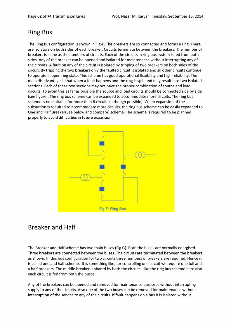
Prof. Nazar M. Karyar Tuesday, September 16, 2014 Transmission Lines Page 62 of 74
Ring Bus The Ring Bus configuration is shown in Fig-F. The breakers are so connected and forms a ring. There are isolators on both sides of each breaker. Circuits terminate between the breakers. The number of breakers is same as the numbers of circuits. Each of the circuits in ring bus system is fed from both sides. Any of the breaker can be opened and isolated for maintenance without interrupting any of the circuits. A fault on any of the circuit is isolated by tripping of two breakers on both sides of the circuit. By tripping the two breakers only the faulted circuit is isolated and all other circuits continue to operate in open ring state. This scheme has good operational flexibility and high reliability. The main disadvantage is that when a fault happens and the ring is split and may result into two isolated sections. Each of these two sections may not have the proper combination of source and load circuits. To avoid this as far as possible the source and load circuits should be connected side by side (see figure). The ring bus scheme can be expanded to accommodate more circuits. The ring bus scheme is not suitable for more than 6 circuits (although possible). When expansion of the substation is required to accommodate more circuits, the ring bus scheme can be easily expanded to One and Half Breaker(See below and compare) scheme. The scheme is required to be planned properly to avoid difficulties in future expansion.
Breaker and Half
The Breaker and Half scheme has two main buses (Fig G). Both the buses are normally energised. Three breakers are connected between the buses. The circuits are terminated between the breakers as shown. In this bus configuration for two circuits three numbers of breakers are required. Hence it is called one and half scheme. It is something like, for controlling one circuit we require one full and a half breakers. The middle breaker is shared by both the circuits. Like the ring bus scheme here also each circuit is fed from both the buses. Any of the breakers can be opened and removed for maintenance purposes without interrupting supply to any of the circuits. Also one of the two buses can be removed for maintenance without interruption of the service to any of the circuits. If fault happens on a bus it is isolated without

Prof. Nazar M. Karyar Tuesday, September 16, 2014 Transmission Lines Page 63 of 74
interruption of supply to any of the circuits. If the middle circuit breaker fails then the breakers adjacent to the buses are tripped so interrupting both the circuits. But if a breaker adjacent to the bus fails then the tripping of middle breaker does not interrupt power supply to circuit associated with healthy breaker. Only the circuit associated with failed breaker is interrupted.
This configuration is very flexible and highly reliable. The relaying of the scheme is complicated as the middle breaker is associated with both the circuits. This scheme is economical in comparison to Double Bus Double Breaker scheme. This scheme also require more space in comparison to other schemes to accommodate more equipments. In one substation you can find two or more schemes implemented as per the requirement. In most of the modern substations it is usual to add one transfer bus in most of the schemes above. Which enhances the availability and maintainability of the system and operational flexibility
Circuit Breaker
In last article we discussed common bus schemes used in substations. We felt the importance of the circuit breaker. Here we will discuss more about the circuit breakers. Although here the primary concern is about the breakers used in HV, EHV or UHV substations the basic is still applicable to low voltage breaker. Also Switchgear is a very common term often used by power system engineers. Switchgear includes circuit breaker, protective devices, and also measuring and control devices. The main function of the circuit breaker is to break and make the circuit. So theoretically a circuit breaker is a switch. The breaker is rated so that is should be capable to make, carry and break load current during normal operation and interrupt large fault current in abnormal conditions. Circuit breaker is the main equipment for controlling power flow and safety of other equipments and personnel. The different associated elements and basic functioning of the circuit breaker is illustrated in the simplified Figure-A. The breaker can be operated by a trained substation personnel by pressing the button at the control room. But during the fault condition it trips automatically.

Prof. Nazar M. Karyar Tuesday, September 16, 2014 Transmission Lines Page 64 of 74
When fault in the line takes place the large fault current is associated with the increase of secondary current in current transformer (CT). This will actuate the relay and relay contact closes. Now as the tripping circuit of the breaker is complete the trip coil is energised. The energised trip coil initiates breaker mechanism for moving the circuit breaker moving contact away from fixed contact. The Arc formed between the moving contact and fixed contact is extinguished by breaker arc extinguishing mechanism. The breaker is open. From the figure it is clear that the breaker trip circuit can be closed by closing of either of the contacts C1 or C2. While C1 is for manual closing by pressing the button at the control panel, the C2 is closed automatically by breaker relay for abnormal over current condition sensed by CT. These two contacts in parallel fulfil the logic OR function. Applying same reasoning it is easy to think that the breaker can be logically conditioned for tripping on other abnormal conditions. The trip circuit is supplied with DC battery source. Independent AC source may be used for trip circuit. It should be noted that for high voltage breaker the fault sensing device is outside the circuit breaker where as in case of low voltage breaker the sensing device is accommodated within the breaker enclosure. During separation of moving contact from fixed contact electric arc is produced between the contacts. Extinguishing of the arc is the most important part of breaker functioning, which greatly influences the breaker design. Actually in low and medium voltage case, the arc extinction is not of much problem. The arc extinguishing is a difficult task in HV and EHV or UHV circuit and is the primary concern for breaker design. The energy stored in the line/circuit inductance is dissipated in the arc and the arc is required to be extinguished reliably.

Prof. Nazar M. Karyar Tuesday, September 16, 2014 Transmission Lines Page 65 of 74
From the above discussion it is observed that the circuit breaker functioning is comprised of three main components.
Sensing and tripping circuit Operating mechanism Arc interruption
The breakers can be classified several ways. The most important classification is the medium used for arc interruption. For low and medium voltage use, air is mainly used as the medium for arc extinction (In past, oil was also used for 430/220 volt system). In HV, EHV and UHV substations oil and gas is used as arc quenching medium (In the past Air Blast breakers were also often used for HV/EHV/UHV application). Like low voltage system, Oil Circuit breakers are also becoming obsolete for higher voltage use. Vacuum is also used for arc quenching. Vacuum circuit breakers are usually used for breakers in the range of 3 kV to 38 kV. In modern EHV and UHV substations SF6 gas breakers have replaced the Oil circuit breakers and Air Blast circuit breakers. But one can still find Oil Breakers and Air Blast Breakers in many old substations. SF6 is a superior gas having good dielectric strength and arc quenching ability which has proved to be a better medium for arc quenching in the breaker. An UHV SF6 Circuit Breaker is displayed below.
The circuit breakers are also available as single tank type or separate tank type. In case of separate tank type, each phase has a separate tank. For EHV application separate tank type breakers are preferred. The circuit breakers can also be classified from the point of view of operating mechanism. The operating mechanism of the circuit breaker may be hydraulic, pneumatic or motor operated types.
The circuit breakers are also classified as live tank type or dead tank type. In case of live tank type breaker the enclosure of the breaker is at line potential. In the dead tank type breaker the enclosure of the breaker is at ground potential. The dead tank type breaker requires additional oil/gas for

Prof. Nazar M. Karyar Tuesday, September 16, 2014 Transmission Lines Page 66 of 74
insulation from the grounded enclosure. Live tank type breaker requires less oil or gas. More on Circuit Breaker is discussed in subsequent articles.
Arcing in Circuit Breaker
Electric Arc
For interrupting power supply to a part of a network or circuit, or to clear a fault, circuit breakers are employed. On receipt of trip signal the circuit breaker operating mechanism operates to separate moving contact from the fixed contact (Fig-A). As the moving contact starts moving away from the fixed contact, the contact area of the tips of both moving contact and fixed contact reduces. But the same current now passes through this reduced contact area. The current density of the contact area increases very much. This situation makes the areas of the tips in contact very hot, may be several thousand degrees celsius. Now as the contacts just separate these hot spots becomes source of electron emission. High energy electrons are emitted from the separated contact tips. This is called thermionic emission.
The other main cause of electron emission is field emission. As the movable contact moves away from the fixed contact voltage difference between the two electrodes (fixed and moving contacts) exist (Fig-B). Which gives rise to an electric field between the electrodes. Electric Field = V / d Where V is the potential difference between the electrodes and d is the separation between the two.

Prof. Nazar M. Karyar Tuesday, September 16, 2014 Transmission Lines Page 67 of 74
So from the above formula it is clear that just after separation when the movable contact has not moved much away, then d is small so the electric field strength is very high (order of several kV per millimetre). High electric field gives rise to emission of high energy electrons from the contact surface. The high speed electrons emitted bombard the molecule or atoms of the medium and dislodge electrons from the atoms. This is secondary emission. The high energy electrons so emitted ionise the gas or oil used as medium. Arc plasma is formed between the fixed and moving contacts. The current continues to flow through the arc plasma between the contacts (see Fig-A). It is clear that just separating the contacts does not automatically break the circuit and flow of current does not stop. The arc is required to be extinguished. More importantly the dielectric strength of the medium between the fixed and moving contacts should be restored quickly, otherwise arc may re-strike between the contacts. This is the job of the arc interruption chamber of the circuit breaker. Several techniques are employed for the arc extinction. The arc can be extinguished by increasing the resistance of the arc path. This is achieved by lengthening the arc or splitting the arc using one of the techniques and by reducing the diameter of the arc by cooling. By increasing the resistance the voltage drop across the arc increases. It achieves such a value that the supply voltage cannot sustain the voltage drop across the arc and the arc is extinguished. Also in AC circuit the current varies sinusoidally so the arc is extinguished at next current zero. Although the arc is extinguished but the medium is having enough ionised particles. Hence to stop the re-striking of arc due to Transient Restriking Voltage the space between the separated contacts should rapidly regain dielectric strength. This can be done by blowing gas or air at high speed to the region between the contacts in Gas or Air Blast breaker. In case of oil circuit breaker rapid flow of oil to the contact region helps regain high dielectric strength. Regaining dielectric strength is the result of recombination of ions and electrons. The working principles of some breakers will be discussed later.

Prof. Nazar M. Karyar Tuesday, September 16, 2014 Transmission Lines Page 68 of 74
Transmission Line Parameters Resistance and Inductance
The transmission lines are modeled by means of the parameters resistance, inductance, capacitance and conductance. Resistance and inductance together is called transmission line impedance. Also capacitance and conductance in parallel is called admittance Here we are not going to derive the formulas rather to develop some concepts about the transmission line parameters. It will help us understand the transmission line modelling and in analyzing the power system. In this article we will discuss about the line resistance and inductance. In the next article we will discuss about line capacitance and conductance.
Resistance
The conductors of the transmission lines have small resistance. For short lines, resistance plays an important role. As the line current increases so do the ohmic loss (I2R loss). When the current exceed a certain value the heat generated due to ohmic loss starts to melt the conductor and the conductor becomes longer that results in more sag. The current at which this condition of conductor is irreversible is called thermal limit of conductor. Short overhead lines should be operated well within this limit. The resistance R of a conductor of length 'l' and cross section 'a' is given by the formula
l R = ρ ---- a
Here ρ is the resistivity of the conductor material which is a constant.
Transmission lines usually use ACSR conductors with spirally twisted strands. So the actual length of the conductor is about 2 % more than the ACSR conductor length. So from the above formula, the resistance of the line is proportionately 2% more than the conductor length. Another important factor is that when the frequency of current increases the current density increases towards the surface of conductor and current density at the center of conductor is less. That means more current flows towards the surface of conductor and less towards the center. This is well known skin effect. Even at power frequency (60/50 Hz) due to this skin effect the effective cross sectional area of conductor is less. Again from the above equation it is clear that the conductor resistance is more for higher frequency. So AC resistance of conductor is more than the DC resistance. Temperature is another factor that influences the resistance of conductor. The resistance varies linearly with temperature. The manufacturers specify the resistance of the conductor and one should use the manufacturers data.
Inductance
For medium and long distance lines the line inductance (reactance) is more dominant than resistance. The value of current that flows in a conductor is associated with another parameter, inductance. We know that a magnetic field is associated with a current carrying conductor. In AC transmission line this current varies sinusoidally, so the associated magnetic field which is proportional to the current also varies sinusoidally. This varying magnetic field induces an emf (or induced voltage) in the conductor. This emf(or voltage) opposes the current flow in the line. This emf is equivalently shown by a parameter known as inductance. The inductance value depends upon the

Prof. Nazar M. Karyar Tuesday, September 16, 2014 Transmission Lines Page 69 of 74
relative configuration between the conductor and magnetic field. Inductance in simple language is the flux linking with the conductor divided by the current flowing in the conductor. In the calculation of inductance the flux inside and outside of the conductor are both taken care of. The inductance so obtained is total inductance. Now onwards if not exclusively mentioned then inductance means total inductance due to conductor internal and external flux linkages. The symbol L is used universally to represent inductance. L is measured in Henry (H). It is usually expressed in smaller unit, milli Henry(mH). Manufactures usually specify inductance value per kilometer or mile. It should be noted that, in all the formulas below inductance L is in Henry per unit length and not simply Henry. Here few cases are depicted.
For a single phase line see the fig-A. The conductor inductance is
L = 2 * 10-7 ln ( D/r1' )
Here D is the distance between the centers of conductors.
r1' = r1 * e-(1/4) = 0.7788 r1
r1 is the actual radius of the conductor. For a single phase line the return path also has inductance say L'. If the return conductor is of radius r2, then
L' = 2 * 10-7 ln ( D/r2' )
Therefore the total inductance of single phase circuit is Lt = L+L' rearranging we get
Lt = 4 * 10 -7 ln [D / √ (r1'. r2
')]

Prof. Nazar M. Karyar Tuesday, September 16, 2014 Transmission Lines Page 70 of 74
For three phase circuit whose three circular conductors are at the corners of equilateral triangle(Fig-B(i)) then the above formula for single phase case is applied here. In this case inductance per phase L is as below:
If the Denominator is renamed as Ds, then
L = 2 * 10-7 ln ( D / Ds )
Here Ds = r' As already said r' is 0.7788 times the actual radius(r) of conductor.

Prof. Nazar M. Karyar Tuesday, September 16, 2014 Transmission Lines Page 71 of 74
For three phase circuit whose three circular conductors are arbitrarily placed (Fig-B(ii)) and the conductors are transposed then,
L = 2 * 10-7 ln [ ∛(D1 . D2 . D3) / Ds ]
Beginning from the single phase line, it is observed that all the three equations for inductance of a phase conductor are similar. Remember that this formula for three phase line is not valid for non-transposed lines. Observing the formula for single phase and three phase lines we can generalize the formula for inductance of a phase line as in the form
L = 2 * 10-7 ln ( D / Ds )
Where D = Geometric Mean Distance (GMD) Ds= Geometric Mean Radius (GMR) In single phase case GMD is simply the distance between the centers of two conductors. In three phase case for conductors equidistant from each other GMD is the distance between any two phase conductors. In the three phase case, for line conductors arbitrarily placed GMD = ∛(D1D2D3 )
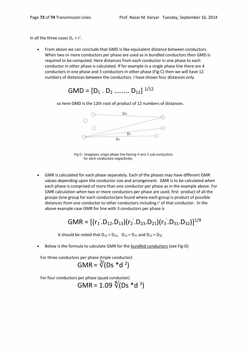
Prof. Nazar M. Karyar Tuesday, September 16, 2014 Transmission Lines Page 72 of 74
In all the three cases Ds = r'.
From above we can conclude that GMD is like equivalent distance between conductors. When two or more conductors per phase are used as in bundled conductors then GMD is required to be computed. Here distances from each conductor in one phase to each conductor in other phase is calculated. If for example in a single phase line there are 4 conductors in one phase and 3 conductors in other phase (Fig-C) then we will have 12 numbers of distances between the conductors. I have shown four distances only.
GMD = [D1 . D2 ........ D12] 1/12
so here GMD is the 12th root of product of 12 numbers of distances.
GMR is calculated for each phase separately. Each of the phases may have different GMR values depending upon the conductor size and arrangement. GMR is to be calculated when each phase is comprised of more than one conductor per phase as in the example above. For GMR calculation when two or more conductors per phase are used, first product of all the groups (one group for each conductor)are found where each group is product of possible distances from one conductor to other conductors including r' of that conductor. In the above example case GMR for line with 3 conductors per phase is
GMR = [(r1'.D12.D13)(r2
'.D23.D21)(r3'.D31.D32)]1/9
It should be noted that D12 = D21, D13 = D31 and D23 = D32
Below is the formula to calculate GMR for the bundled conductors (see Fig-D)
For three conductors per phase (triple conductor)
GMR = ∛(Ds *d 2)
For four conductors per phase (quad conductor)
GMR = 1.09 ∜(Ds *d 3)

Prof. Nazar M. Karyar Tuesday, September 16, 2014 Transmission Lines Page 73 of 74
How to calculate GMD of three phase line with bundled conductors? For an example see Fig-E where three phase bundles (triple conductror) are placed horizontally on transmission towers. In this case the distance between the conductors (D) is taken as distance between the centers of bundled conductors.
So, GMD = ∛(D.D.2D)
You can also calculate considering the distance from each bundled conductors of one phase to other conductors of two other phases. But the GMD calculated does not vary significantly from our simple form above. This is due to the fact that D is quite larger than d.
For ACSR conductors GMR is specified by the manufacturer.If this GMR is called Ds. For example if two such ACSR conductors(twin conductor) are used in a bundle for each phase. The GMR of the phase conductor arrangement is calculated imagining that the supplied GMR (or Ds) as the equivalent radius of ACSR conductor.
Hence if d is the distance between the centers of the two ACSR conductors, similar to the formulas in Fig-D,
GMR= [(Ds.d).(Ds.d)]1/4 =√(Ds . d)

Prof. Nazar M. Karyar Tuesday, September 16, 2014 Transmission Lines Page 74 of 74
We will discuss Inductance and capacitance for double circuit after discussing line capacitance in next article.
Usually it is not always possible to arrange the phase lines equilaterally on the towers. To make the inductance and capacitance of all the three phases nearly equal, the conductors are transposed. Which means the conductors exchange the position after 1/3 rd of line length. By transposing the inductance and capacitance of all the three phase lines are made nearly equal. This helps balancing the three phase voltages at the receiving end of the line. Although the above formulas are derived considering transposition, the same formulas are also used for non-transposed cases to get approximate values. Transmission line capacitance and conductance