Transmission Lines and E.M. Waves Lec 30
35
Tr ansmission Lines and E.M. Waves Prof R.K. Shevgaonkar Department of Electrical Engineering Indian Institte of Technolog! "om#a! Lectre$%& Welcome, in the last lecture we investigated the wave propagation in some arbitrary direction with respect to the coordinate axis. Our main objective is to fi nd out the wa ve pr opagat ion in a bound me di um and it ha s be en mentioned earlier that when you are having a bound medium the freedom of choosi ng the coor di na te axis is not rea ll y ther e beca use choosi ng the coordinate axis in a particular direction may simplify the problem at least algeb raica lly . So norma lly when we are having the medium boundaries we choose the coordinate axis so that it aligns along the boundaries and then the wave propagates in arbitrary direction with respect to the coordinate axis because the wave is now incident on the bo undary or some arbitrary angle. In today’s lecture we will investigate the propagation of a plane wave at media interface.
-
Upload
vishnu-shashank -
Category
Documents
-
view
218 -
download
1
Transcript of Transmission Lines and E.M. Waves Lec 30
8/20/2019 Transmission Lines and E.M. Waves Lec 30
http://slidepdf.com/reader/full/transmission-lines-and-em-waves-lec-30 1/35
Transmission Lines and E.M. Waves
Prof R.K. Shevgaonkar
Department of Electrical Engineering
Indian Institte of Technolog! "om#a!
Lectre$%&
Welcome, in the last lecture we investigated the wave propagation in some
arbitrary direction with respect to the coordinate axis. Our main objective is
to find out the wave propagation in a bound medium and it has been
mentioned earlier that when you are having a bound medium the freedom of
choosing the coordinate axis is not really there because choosing the
coordinate axis in a particular direction may simplify the problem at least
algebraically. So normally when we are having the medium boundaries we
choose the coordinate axis so that it aligns along the boundaries and then the
wave propagates in arbitrary direction with respect to the coordinate axis
because the wave is now incident on the boundary or some arbitrary angle.
In today’s lecture we will investigate the propagation of a plane wave at
media interface.

8/20/2019 Transmission Lines and E.M. Waves Lec 30
http://slidepdf.com/reader/full/transmission-lines-and-em-waves-lec-30 2/35
!efer Slide "ime# $%#&% min'
What you are now saying is instead of having an infinite medium if I divide
the medium into two semi infinite media so I have a media interface, on the
left side of this line we are having a medium which is infinite, on the right
side we have a medium which is again infinite and the medium properties
abruptly change at this location called a media interface. So let us say we
have (edium % on the left side of this and we have (edium ) on the right
side and let us assume that the conductivity for both the media is still *ero
that means the media is still lossless but the permeability and permittivity
are different for these two media. So let us say the permeability for this
(edium % is given by +%, permittivity is given by % and for (edium ) the
permeability is given by +) and the permittivity is given by ).

8/20/2019 Transmission Lines and E.M. Waves Lec 30
http://slidepdf.com/reader/full/transmission-lines-and-em-waves-lec-30 3/35
!efer Slide "ime# $)#- min'
/et us say now we orient the coordinate system such that the media interface
is in the xy0plane. So along this direction we have coordinate axis x
perpendicular to this axis * and perpendicular to the plane of the paper that is
the arrow coming outwards normal to the plane of the paper that is the y
direction. We can again verify that we must have the right handed coordinate
system so if my fingers go from x to y where y is coming outwards from the
paper then my thumb must point in the direction of * so this is the correct
right handed coordinate system.

8/20/2019 Transmission Lines and E.M. Waves Lec 30
http://slidepdf.com/reader/full/transmission-lines-and-em-waves-lec-30 4/35
!efer Slide "ime# $1#&- min'
2ow let us say we have a wave which is incident on this dielectric interface
at some arbitrary angle with respect to the coordinate axis. So I have a wave
which is incident at some arbitrary angle li3e that, this is the direction of the
wave so essentially this is the wave vector for the wave which is incident on
the dielectric.
2ow specifically we are as3ing 4uestions li3e when this uniform plane wave
is incident on this dielectric interface then what will happen to this wave.
Intuitively it appears that part of the energy will get transferred to the second
medium so that will again constitute some 3ind of wave propagation but also
what is not obvious at this moment is that part of the energy will get from
the interface, this is what essentially we will argue that if the wave is
incident on this interface we essentially re4uire two 3inds of fields, one

8/20/2019 Transmission Lines and E.M. Waves Lec 30
http://slidepdf.com/reader/full/transmission-lines-and-em-waves-lec-30 5/35
which is in the second medium and also the fields in the first medium all
have to be modified to satisfy the boundary conditions.
So essentially when the wave is incident on the dielectric interface, part of the energy will be transferred to the second medium but also the part of the
energy will come bac3 to the first medium and that is what essentially we
will investigate.
When the energy comes bac3 into the first medium or goes to the second
medium what happens to plane wave nature, which direction the energy will
be going are 4uestions essentially we will have to as3, also we have to as3
for what is the magnitude of the field which goes to second medium, how
much power is going to transferred to second medium.
So the analysis of the plane wave at interface essentially includes finding out
the direction in which the waves will be moving in the two media, how
much power get transferred from one medium to another medium, how
much power comes bac3 from the interface to the first medium itself, what
happens to the direction of the electric field that means what happens to the
polari*ation of the electromagnetic wave and so on.
So in this lecture and in the following lectures we will essentially discuss
these issues related to the propagation of uniform plane wave across a mediainterface. 5nd since you have ta3en conductivity *ero for both these media
we can at moment we call this as 6ielectric (edia so this is the 6ielectric
(edium %, this is the 6ielectric (edium ). So essentially at the moment we

8/20/2019 Transmission Lines and E.M. Waves Lec 30
http://slidepdf.com/reader/full/transmission-lines-and-em-waves-lec-30 6/35
are investigating propagation of the uniform plane wave at a dielectric media
interface, on both sides we are having media which have dielectrics.
2ow let us say this is ma3ing an angle with respect to this direction that this
angle is given by some 7i.
!efer Slide "ime# $8#$$ min'
2ow you find a certain 4uantities here that is if I say that xy9plane is the
media interface that means in that plane suddenly the medium properties
change the medium is uniform in the xy direction only suddenly it changes
this point along this * direction and without losing generality we can say this
4uantity * : $. So let us say the origin of this coordinate axis at the interface
and the wave vector is ma3ing an angle 7i with respect to this direction. 2ow
this * direction is perpendicular to the media interface so we call this as the
8/20/2019 Transmission Lines and E.M. Waves Lec 30
http://slidepdf.com/reader/full/transmission-lines-and-em-waves-lec-30 7/35
normal to the media interface. So this line the * axis is the normal to the
dielectric media interface.
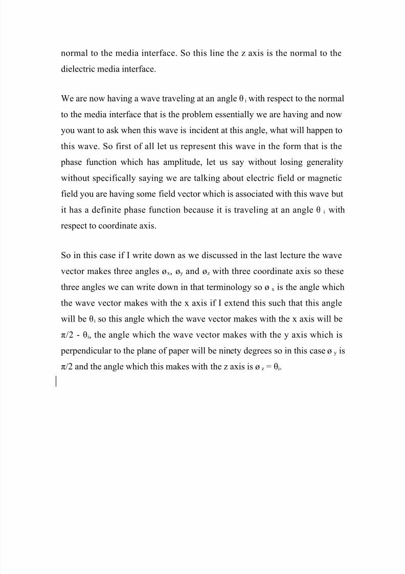
We are now having a wave traveling at an angle 7i with respect to the normalto the media interface that is the problem essentially we are having and now
you want to as3 when this wave is incident at this angle, what will happen to
this wave. So first of all let us represent this wave in the form that is the
phase function which has amplitude, let us say without losing generality
without specifically saying we are tal3ing about electric field or magnetic
field you are having some field vector which is associated with this wave but
it has a definite phase function because it is traveling at an angle 7 i with
respect to coordinate axis.
So in this case if I write down as we discussed in the last lecture the wave
vector ma3es three angles ;x, ;y and ;* with three coordinate axis so these
three angles we can write down in that terminology so ; x is the angle which
the wave vector ma3es with the x axis if I extend this such that this angle
will be 7i so this angle which the wave vector ma3es with the x axis will be
<=) 9 7i, the angle which the wave vector ma3es with the y axis which is
perpendicular to the plane of paper will be ninety degrees so in this case ;y is
<=) and the angle which this ma3es with the * axis is ;* : 7i.

8/20/2019 Transmission Lines and E.M. Waves Lec 30
http://slidepdf.com/reader/full/transmission-lines-and-em-waves-lec-30 8/35
!efer Slide "ime# $>#&) min'
Once I 3now these three angles which the wave vector ma3es with the three
coordinate axes then I can write down the direction cosines and I can write
down the phase function. Since the medium properties for this (edium % are
+% and % we have the phase constant of this first medium is ?% that is e4ual
to @ s4uare root +% % and in the second medium we have phase constant ? )
that is e4ual to @ s4uare root +) ).

8/20/2019 Transmission Lines and E.M. Waves Lec 30
http://slidepdf.com/reader/full/transmission-lines-and-em-waves-lec-30 9/35
!efer Slide "ime# %$#)) min'
So I 3now in both media the phase constant for a plane wave and we 3now
the angle which the wave vector ma3es with the three coordinate axes. So let
us say I have some field represented by this wave which is having a vector
and the phase function will be given as we saw last time as follows.
/et us say I have some field which is incident and let me can call that as
some Ai bar where A could represent the electric field or magnetic field
which is having a magnitude term so let us say A $i bar which is a vector and
then you are having a phase function which is e to the power 0j since the
wave is incident in (edium % so this phase constant is ? % so this is ?% into
cos ;x x B cos ;y y B cos ;* *'.
2ow since ;x is <=) 9 7i so cos ;x is sin 7i, cos ;y which is cos <=) is *ero and
cos ;* is cos 7i. So from here we get cos ;x is cos<=) 9 7i' which is again

8/20/2019 Transmission Lines and E.M. Waves Lec 30
http://slidepdf.com/reader/full/transmission-lines-and-em-waves-lec-30 10/35
e4ual to sin 7i, cos ;y : cos <=) that is *ero and cos ;* : cos 7i that will be cos
7i.
!efer Slide "ime# %)#1- min'
If I substitute this in the expression for the fields in general the incident field
we call this wave as the incident wave this is incident on the dielectric media
and this is what the suffix denotes this i essentially gives you the incident
field so let us call this as incident wave so we have the field for the incident
wave which is this magnitude amplitude term e to the power 9j?% x sin 7i B *
cos 7i' where this 4uantity is *ero because of ;y is *ero

8/20/2019 Transmission Lines and E.M. Waves Lec 30
http://slidepdf.com/reader/full/transmission-lines-and-em-waves-lec-30 11/35
!efer Slide "ime# %1#&1 min'
So the wave which is traveling at an angle 7i with respect to the normal to
the interface can be represented by field which is li3e this so if I loo3 at
some instant of time if I loo3 what is the variation of the field amplitude and
the function of x and * and also y we can obtain the field variation by ta3ing
the real part of this 4uantity so if I ta3e the field amplitude at some instant of
time the amplitude per magnitude will be the real part of this 4uantity so real
part of Ai bar will be A$i bar cosine of this angle which is ?% times this
4uantity.
/et us say I am interested in finding out what is the variation of the phase in
the media interface so I am not worried about how the phase is varying in *
direction just it has a phase constant which is ?% times A times 7i but at the
moment let us say we want to find out what is the phase variation which I
am going to get at the interface when the wave is incident at this angle since

8/20/2019 Transmission Lines and E.M. Waves Lec 30
http://slidepdf.com/reader/full/transmission-lines-and-em-waves-lec-30 12/35
I have ta3en the origin * : $ here then I can substitute * : $ in this and I get
the magnitude of the field in xy9plane so that will be your A$i cos ?% x sin7i'
!efer Slide "ime# %-#-C min'
So if I loo3 at the field variation in this xy9plane the field is having a
variation which is cosine variation in the x direction and it does not have any
variation in the y direction. So essentially this is my media interface if I plot
the field amplitude the field amplitude will vary li3e in the x direction and it
is constant in the y direction. So essentially it has created some 3ind of a
corrugated surface if I want to visuali*e what this field variation is, this will
be more li3e a corrugated surface in this plane where the corrugations are
oriented in the y direction because the direction perpendicular to the plane of
the paper is the y direction. So I got something li3e an asbestos sheets which
have nice corrugated surfaces.

8/20/2019 Transmission Lines and E.M. Waves Lec 30
http://slidepdf.com/reader/full/transmission-lines-and-em-waves-lec-30 13/35
!efer Slide "ime# %8#$) min'
One thing we note here is if the wave is incident in this direction the
amplitude variation will appear li3e a corrugated surface in this xy9plane on
the interface or it is e4uivalent to having a phase gradient in the x direction
which is ?% sin7i. So I can visuali*e this field either as a amplitude variation
which is li3e this in the x direction and constant in the y direction or
e4uivalently I can say that it is having a phase variation which is ?% x sin7i or
the special gradient of the phase will be ?% sin7i.
So, this one has a phase gradient which is the phase change per unit length in
the x direction will be e4ual to 9?% sin7i. If I ma3e 7i : $ then the phase
gradient will become *ero so the phase will become constant and that is what
will be the case if the wave is moving perpendicular to this plane since the
wave was coming perpendicular li3e this then this 7 i will be *ero and then
this will be constant phase plane so I will not have any phase gradient in this
plane and wave will be traveling normal to it.

8/20/2019 Transmission Lines and E.M. Waves Lec 30
http://slidepdf.com/reader/full/transmission-lines-and-em-waves-lec-30 14/35
!efer Slide "ime# %#1> min'
So direction of the wave as it changes introduces a phase gradient on this
plane. So creating a phase gradient and tilting the direction of the wave are
e4uivalent that means if the wave direction is changed I get a phase gradient
e4uivalently if I create a phase gradient I will get a wave which will be
oriented at some other direction which will satisfy the phase gradient. So
from here if the phase gradient is given to you if I e4uate the phase gradient
with 9?% sin7i then I will get some 4uantity 7 i that is the effective direction at
which the wave is traveling.
2ow here what we did is we started from the wave direction and we say this
is the phase gradient was created. Dut now we can go reverse and say if the
phase gradient was created by some mechanism then e4uivalently the wave
is traveling at an angle which will satisfy the phase gradient to be e4ual to
this.

8/20/2019 Transmission Lines and E.M. Waves Lec 30
http://slidepdf.com/reader/full/transmission-lines-and-em-waves-lec-30 15/35
2ow in this case the wave was traveling in this direction as we saw was
ma3ing an angle 7i with respect to this so if I ta3e a direction li3e that this
was the angle 7i. So this wave which is moving at an angle 7 i with respect to
the normal has created this phase gradient, alternatively I can say if I had
created this phase gradient it would be e4uivalent of having a phase which is
coming li3e this.
2ow, if I consider this dielectric interface it will be immediately clear to you
that even if the wave was incident from this direction exactly at same angle
7i then it also created the same phase gradient but they are ma3ing exactly
the same angles with respect to the normal.
!efer Slide "ime# )$#&C min'
So whether the wave is coming this way on the interface or the wave is
coming this way from the interface both are going to create identically same
phase gradient. So the wave which was traveling through interface li3e this

8/20/2019 Transmission Lines and E.M. Waves Lec 30
http://slidepdf.com/reader/full/transmission-lines-and-em-waves-lec-30 16/35
will correspond to this phase gradient, if the wave was passing through the
interface li3e this it will create the wave gradient which is li3e this.
2ow this side we have (edium %, this side we have (edium ). So firstly if Ita3e this wave and ta3e this on this side essentially the same phase gradient
corresponds to the wave which travels away from the interface at same angle
because this is the phase gradient which corresponds to this plane in the
same direction. So the wave which is approaching to the interface and wave
which is going away from the interface at the same angle intersect the
normal create the same phase gradient and that is a very important thing.
Dut we understand this then we can now as3 a 4uestion when the wave was
incident on this dielectric interface what would this wave doE "his wave
would try to excite certain fields in this second medium because of the
continuity of the fields.

8/20/2019 Transmission Lines and E.M. Waves Lec 30
http://slidepdf.com/reader/full/transmission-lines-and-em-waves-lec-30 17/35
!efer Slide "ime# ))#%- min'
2ow if I want to maintain the continuity of the electric and the magnetic
fields both but once the electric and magnetic fields are induced into second
medium they see infinite medium ahead of it that means again they
constitute a wave phenomenon and since the medium seen ahead of them is
infinite medium they again see a transverse electromagnetic behavior for the
wave.
2ow the wave is in the second medium so the ratio of the electric field and
magnetic field again is decided by the medium parameter the characteristic
impedance or the intrinsic impedance of the second medium whereas the
electric and magnetic field ratio was decided by the intrinsic impedance of
(edium % in this region. So if I say that the fields are continuous across the
boundary on one side of the ratio of F and G are satisfied by the intrinsic
impedance of this medium and the other side the F and G are related to the
intrinsic impedance of the second medium. It is immediately clear to me that

8/20/2019 Transmission Lines and E.M. Waves Lec 30
http://slidepdf.com/reader/full/transmission-lines-and-em-waves-lec-30 18/35
just by having the fields on the other side and the original field which are on
this side I cannot satisfy them all together for both electric and magnetic
fields. So what that means is I have to induce certain fields in the first
medium itself or in other words, we have to modify the fields in the first
medium so that the boundary conditions can be satisfied for both electric and
magnetic fields at the interface.
So essentially there will be some fields which will be induced in this
medium, there will be some fields which will be induced in this medium and
since the induced phenomena is due to this phase variation because this is
the one which is created by the incident field both these fields are induced
on two sides are the interface will have the same phase variation because
that is the origin the induced fields are because of this field which is incident
which is having the phase variation.
So essentially what we note now that the field which goes into the second
medium, the field which get induced into the first medium also should have
a phase variation which is same as the phase variation because they are
caused because of this and since this phase variation is uniform in this
direction these fields must also constitute a phenomenon for which the field
is constant in this direction and I mentioned since this fields are time varying
fields, again they will constitute a wave phenomena so the induced field in
this medium will constitute a wave phenomena, fields in this medium againwill constitute a wave phenomena and these fields will travel away from this
boundary this fields which are here will again go away from this boundary.
So we will have two types of waves which will be going away from the

8/20/2019 Transmission Lines and E.M. Waves Lec 30
http://slidepdf.com/reader/full/transmission-lines-and-em-waves-lec-30 19/35
interface one is in this direction anther is in this direction and one will be
incident field.
So we have something which is going li3e that, there is another way whichgoes in li3e this and all this three waves has the same phase variation that is
what the important thing to note.
!efer Slide "ime# )-#&& min'
2ow the wave vector for this wave lies in the x*9plane which is plane of the
paper. So if the amplitude is constant in this plane there is no phase gradient
in this plane then the wave normal lies in the plane which is x* plane. If we
define the plane of the paper as the plane of incidence which is the plane
contains the wave vector and the normal that is the plane which is the plane
of the paper we say this is plane of incidence. So wave vector for the
incident wave lies in the plane of incidence and this plane of incidence is
perpendicular to the direction in which this amplitude is remaining constant

8/20/2019 Transmission Lines and E.M. Waves Lec 30
http://slidepdf.com/reader/full/transmission-lines-and-em-waves-lec-30 20/35
which is this y direction but the same is true for two waves which are created
which are induced because of the dielectric medium interface.
!efer Slide "ime# )C#-8 min'
So you are having a uniform variation for this field also that means the wave
vector corresponding to these two waves also must lie in this plane which is
the plane of incidence. So what we conclude is ma3e a very important
conclusion that the wave vector for the incident wave for this wave induces
which is in second medium and the wave vector which is going to first
medium all three lie in the same plane then that plane is the plane of
incidence. 5s we mentioned this wave incidence is going away from this
interface this will carry some energy so we will say what ever energy came
to the interface part of the energy was reflected from the interface and part
of the energy was transmitted.

8/20/2019 Transmission Lines and E.M. Waves Lec 30
http://slidepdf.com/reader/full/transmission-lines-and-em-waves-lec-30 21/35
So in general when the wave is incident on a dielectric interface there will be
a reflected wave which will carry away some energy which was brought by
the incident wave and there will be a transmitted wave which will ta3e the
energy to the second medium. So we call this wave as the "ransmitted wave
and we call this as the !eflected wave. "he "ransmitted wave is also
referred as !efracted wave and this wave which the energy towards the
dielectric interface again is the Incident wave.
!efer Slide "ime# )#&1 min'
So now we have something important conclusions, when the uniform plane
wave is incident on a dielectric interface at an angle we induce two waves in
which one is called !eflected wave which is going away from the interface
(edium %, we induce another wave which is "ransmitted wave which is
going away from the interface (edium ).

8/20/2019 Transmission Lines and E.M. Waves Lec 30
http://slidepdf.com/reader/full/transmission-lines-and-em-waves-lec-30 22/35
5ll these three waves will have the same phase variation which is 9?% sin 7i
into x which is the phase gradient and all these wave vectors for these three
waves lie in the same plane that is the plane of incidence.
2ow if you recall the light is a transverse electromagnetic wave and in the
high school we had studied the laws of reflection for light and the first law
of reflection was the incident ray, the reflected ray and the refracted ray lie
in the same plane which is the plane of incidence. So essentially the
statement the first law of reflection comes from matching this phase
condition on the interface and that says that these three vectors lie in the
same plane.
2ow the wave vector in optics is referred to as the direction of the ray so this
is the ray in which the light moving. Gowever, we call the direction as the
wave vector as we go to general Flectromagnetics. So we are having a
general statement called the first law of reflection that is the wave vector for
incident, transmitted and reflected wave lie in the same plane of incidence
and the plane of incidence is the plane which contains the wave vector and
the normal to the interface. So we got the first law of reflection established
by this condition.
2ow the next thing is that when the waves are moving in this direction, in
what direction the wave would be moving with respect to normalE Since this
angle is 7i and this medium is same the phase gradient what ever I have if I
divide that 4uantity by ?% and ta3e sin inverse of that then that would give
me the direction of the wave propagation in that particular medium. So the
direction at which the wave moves is if I 3now the phase gradient the first

8/20/2019 Transmission Lines and E.M. Waves Lec 30
http://slidepdf.com/reader/full/transmission-lines-and-em-waves-lec-30 23/35
phase gradient what ever is created if I divided that by the phase constant of
that medium then sine of the angle at which the wave travels is given by that
4uantity.
So from here I can write the phase gradient divided by the phase constant,
the angle which the wave ma3es with normal is 7 that is nothing but sine
inverse of the phase gradient divided by the phase constant. So somebody
has given me the phase gradient then I can ta3e the phase gradient divided
by the phase constant in that medium ta3e the sine inverse of that 4uantity
and that essentially gives me the direction of the wave motion in that
medium.
So in this case in (edium %, let us say this angle at which the reflected wave
goes is denoted by 7r the angle of reflection and let us say the wave goes is
given by 7t which we call as theta transmission angle so we have a situation
where the incident wave is at a angle 7i with respect to normal the reflected
angle is at a angle 7 r with respect to normal and the transmitted wave is the
angle 7t with respect to normal.

8/20/2019 Transmission Lines and E.M. Waves Lec 30
http://slidepdf.com/reader/full/transmission-lines-and-em-waves-lec-30 24/35
!efer Slide "ime# 11#) min'
2ow we are having a situation with one wave is li3e that let us say this is my
normal this is the angle 7 i something goes at some other angle this is my
reflected wave let us say this angle is 7r at some other angle I call this as
transmitted wave let us say this angle is 7 t. "his is incident wave, this is
reflected wave and this is transmitted wave. 5nd I am having a phase
gradient on this surface which is 9?% sin7i. I put a minus sign here.
8/20/2019 Transmission Lines and E.M. Waves Lec 30
http://slidepdf.com/reader/full/transmission-lines-and-em-waves-lec-30 25/35
!efer Slide "ime# 1&#) min'
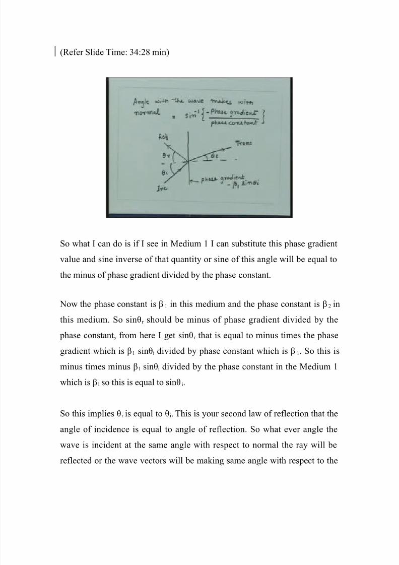
So what I can do is if I see in (edium % I can substitute this phase gradient
value and sine inverse of that 4uantity or sine of this angle will be e4ual to
the minus of phase gradient divided by the phase constant.
2ow the phase constant is ?% in this medium and the phase constant is ?) in
this medium. So sin7r should be minus of phase gradient divided by the
phase constant, from here I get sin7r that is e4ual to minus times the phase
gradient which is ?% sin7i divided by phase constant which is ?%. So this is
minus times minus ?% sin7i divided by the phase constant in the (edium %
which is ?% so this is e4ual to sin7i.
So this implies 7r is e4ual to 7i. "his is your second law of reflection that the
angle of incidence is e4ual to angle of reflection. So what ever angle the
wave is incident at the same angle with respect to normal the ray will be
reflected or the wave vectors will be ma3ing same angle with respect to the

8/20/2019 Transmission Lines and E.M. Waves Lec 30
http://slidepdf.com/reader/full/transmission-lines-and-em-waves-lec-30 26/35
normal. "his will be going towards the interface this will be going away
from the interface but these two angles are e4ual. So we see another
important conclusion from matching of the phase angle that these two angles
are e4ual. "his is in medium one which was for the reflected wave.
"he same thing we can do for the second medium and that is if I go to
(edium ) then the angle which this thing ma3es is 7 t so sin7t should be
e4ual to minus of phase gradient divided by the phase constant but the phase
constant in this medium is ?% so from here we get sin7t is e4ual to minus of
minus ?%sin7i divided by ?) because now we are having (edium ). So from
here essentially I get, ?% sin7i is e4ual to ?) sin7t.
!efer Slide "ime# 18#&1 min'

8/20/2019 Transmission Lines and E.M. Waves Lec 30
http://slidepdf.com/reader/full/transmission-lines-and-em-waves-lec-30 27/35
5nd we 3now ?% and ?) in medium in which ?% is nothing but @ s4uare root
+%% and ?) is @ s4uare root +)) so if I substitute in this, this will be @ s4uare
root of +%% sin7i that is e4ual to @ s4uare root of +)) sin7t.
!efer Slide "ime# 1#)1 min'
Gere both sides cancel so this relation is independent of what is the
fre4uency of the wave and that is s4uare root of +%% sin7i is e4ual to s4uare
root of +)) sin7t. "his relation is nothing but the Snell's la( which we have
already studied in our high school.
Of course, when we are studying the Snell’s law there we tal3 in terms of the
refractive indices of the medium and we dealt with only the dielectric media
so if we did not have the permeability problem because the materials were
not magnetic. So we tal3ed only in terms of refractive indices and we can
see from here how do we get the special case that when the media are only

8/20/2019 Transmission Lines and E.M. Waves Lec 30
http://slidepdf.com/reader/full/transmission-lines-and-em-waves-lec-30 28/35
dielectrics and the permeability of the medium is same on both sides. "he
relation essentially reduces to the relation in terms of the refractive indices.
Dut this is the important law which tells you the direction of the transmittedwave with respect to the direction of the incident wave for the given media
parameter. So we can call this as the generali*ed Snell’s law.
!efer Slide "ime# 1>#- min'
2ow, from here we can calculate the dielectric medium for which the
permeability is same so if I ta3e pure dielectric media then for this media + %
: +) : +$ and then the Snell’s law essentially would be s4uare root of % sin7i
: s4uare root of ) sin7t and we can write down the % as $ times r% the
relative permittivity so the s4uare root of % is e4ual to s4uare root of $ into
r% that is e4ual to s4uare root of $ and as we have seen s4uare root of r% is
nothing but the refractive index of the medium so we can call that as n %
where n% is refractive index of (edium %.

8/20/2019 Transmission Lines and E.M. Waves Lec 30
http://slidepdf.com/reader/full/transmission-lines-and-em-waves-lec-30 29/35
Similarly we can have s4uare root of ) is e4ual to s4uare root $ r) that is
e4ual to s4uare root of $ into n) where n) is refractive index of medium two.
!efer Slide "ime# &)#$C min'
So if I substitute this in your generali*ed Snell’s law then this s4uare root of
epsilon cancel on both sides so I will get finally a relation which will be n %
sin7i : n) sin7t or the way we write the Snell’s law sin7 t will be n one upon
n%=n) sin7i.
"his is the law you are familiar with because we have already studied this
law in optics in our high school physics that if a light ray is incident at an
angle 7i and the refractive indices of the media are given by n % and n) then
the transmitted or the refracted angle which is 7 t that will be related by this.
So this was a special case of the Snell’s law for dielectrics.

8/20/2019 Transmission Lines and E.M. Waves Lec 30
http://slidepdf.com/reader/full/transmission-lines-and-em-waves-lec-30 30/35
In fact when we studied this law in high school physics they appear li3e
these laws came from no where. Gowever, this law essentially comes from
the wave nature of the light and since light is a transverse electromagnetic
wave when it is incident on a dielectric interface it has to satisfy certain
phase conditions and from the phase condition we establish these laws of
reflection and refraction.
So let me summari*e what we did we started with a wave propagation in
some arbitrary direction then we said if the wave is propagating in some
arbitrary direction it creates a phase gradient on the media interface this
phase gradient is same for the wave which is induced on two sides of the
media which we call the transmitted wave and reflected wave and then we
found that changing the direction of the wave and creating the phase
gradient are essentially e4uivalent so if I change the direction of the wave I
get a phase gradient conversely if I create a phase gradient I get a change the
direction of the wave.
So what we find here is that the fields which are induced have the same
phase gradients which are created on the interface and from there essentially
we can find out the directions in which the waves will be traveling. So we
found this relation that the direction of the wave propagation is we can find
out from here that is the angle of the wave which it ma3es with the normal
will be minus times the phase gradient divided by the phase constant in that
medium sine inverse of that gives me the angle with which finally the wave
will be traveling at that medium. Hsing this nature essentially we establish
the laws of reflection and also the Snell’s law which gives the relationship
between the incident and the transmitted wave.
8/20/2019 Transmission Lines and E.M. Waves Lec 30
http://slidepdf.com/reader/full/transmission-lines-and-em-waves-lec-30 31/35
Once you understand this then the analysis of wave propagation across the
dielectric media is 4uite straight forward. "he idea here is that you write
down the phase function for both the media for all the three waves match the boundary conditions at the interface and then find out the amplitude of
electric and magnetic fields in this media for these two wave with respect to
the incident wave.
So let us see if I have a incident wave having an amplitude which is A i of a
electric field with is Fi or magnetic field Gi. "hen we want to find out what
are the relative amplitudes of the electric and magnetic fields for the
reflected wave and for the transmitted wave.
So let us say we have a wave which will be having electric and magnetic
fields. now the problem essentially we want to investigate is, there is a wave
which is incident on this we 3now this is going to be reflected at same angle
part of the thing this angle now is 7i and this angle also is now theta 7i
because 7r : 7i and this angle is theta 7 t. "his is the incident wave so let us
say this one had a electric field which is given by Fi bar, say I ta3e electric
field for this is given by Fr bar and I ta3e the electric field which is given by
Ft bar.
So we have a magnitude for the electric field. "hese are not directions for
electric fields these are the wave vectors electric field will be oriented in
some direction which will be perpendicular to the wave vector. Dut if you
have the amplitude of these three fields which are given by F i, Fr and Ft we
want to find out what is the relationship between these two so what is the

8/20/2019 Transmission Lines and E.M. Waves Lec 30
http://slidepdf.com/reader/full/transmission-lines-and-em-waves-lec-30 32/35
ratio of this and this and that 4uantity we call as a transmission coefficient
for this interface and the ratio of F$ and Fi we call as the reflection
coefficient for this interface.
!efer Slide "ime# &#)$ min'
So we again have the 4uantities which are we are familiar in some sense
because we have seen the reflection coefficient in case of transmission line
that is when ever we are having impedance mismatch then the part of the
energy is reflected.
8/20/2019 Transmission Lines and E.M. Waves Lec 30
http://slidepdf.com/reader/full/transmission-lines-and-em-waves-lec-30 33/35
!efer Slide "ime# &>#&$ min'
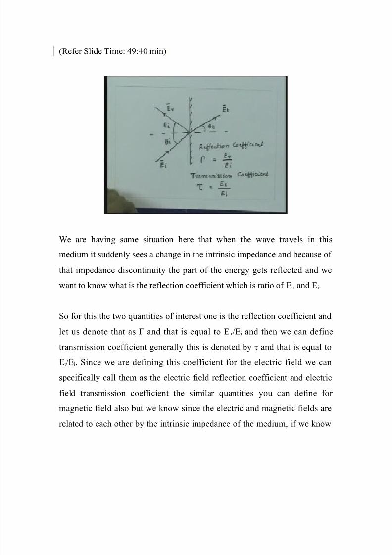
We are having same situation here that when the wave travels in this
medium it suddenly sees a change in the intrinsic impedance and because of
that impedance discontinuity the part of the energy gets reflected and we
want to 3now what is the reflection coefficient which is ratio of Fr and Fi.
So for this the two 4uantities of interest one is the reflection coefficient and
let us denote that as and that is e4ual to F r =Fi and then we can define
transmission coefficient generally this is denoted by J and that is e4ual to
Ft=Fi. Since we are defining this coefficient for the electric field we can
specifically call them as the electric field reflection coefficient and electric
field transmission coefficient the similar 4uantities you can define for
magnetic field also but we 3now since the electric and magnetic fields are
related to each other by the intrinsic impedance of the medium, if we 3now

8/20/2019 Transmission Lines and E.M. Waves Lec 30
http://slidepdf.com/reader/full/transmission-lines-and-em-waves-lec-30 34/35
this 4uantity is electric field in the three media then we can find out
appropriately the magnetic fields also.
"he important thing to note here is that the wave which was incident on thiswas the transverse electromagnetic wave so the ratio of F and G was e4ual
to intrinsic impedance in this medium, the ratio of the electric and magnetic
field for this wave is also intrinsic impedance of this medium for this again a
traverse electromagnetic wave and this wave is again a traverse
electromagnetic wave so the ratio for the electric and magnetic field for this
medium is also intrinsic impedance. So if I say the intrinsic impedance for
this medium is let us say K% and intrinsic impedance for this medium is K) we
3now for this medium your Fi=Gi : K%, also Fr =Gr : K% and Ft=Gt : K).
!efer Slide "ime# -%#)- min'
So using these relations and the boundary conditions at the interface now we
will investigate what will be the reflection and the transmission coefficient.

8/20/2019 Transmission Lines and E.M. Waves Lec 30
http://slidepdf.com/reader/full/transmission-lines-and-em-waves-lec-30 35/35
Leep in mind that since we are now dealing with the vector 4uantities the
electric and magnetic fields will in general ma3e an arbitrary angle with
respect to this plane so you may have electric field which might be oriented
at some angle li3e this. So normally what we do we decompose the problem
into ta3ing the component of the electric field in the direction perpendicular
to the plane and a direction which is in the plane.
So essentially what we do is any electric field we decompose into two cases
or any general case we decompose into two what we call as the parallel
polari*ation where electric field lies in the plane of incidence and a
perpendicular polari*ation where electric field lies perpendicular to the plane
of incidence. So we have to find out these 4uantities for these two cases for
parallel polari*ation and perpendicular polari*ation and once we get that
then we can get the total characteristic of the wave which is polari*ed at an
arbitrary angle with respect to the plane of incidence.
So, in the next lecture essentially we will ta3e these two cases specifically
the parallel and perpendicular polari*ation and then investigate their
reflection and transmission properties across the dielectric media.
"han3 you.