
transm10 speed
196
Fuller ® Heavy Duty Transmissions Service Manual Fuller Heavy Duty Transmissions TRSM2400 November 2008 FR-11210B FR-12210B FR-13210B FR-14210B FR-15210B FR-9210B FRF-11210B FRF-12210B FRF-13210B FRF-14210B FRF-15210B FRF-9210B FRO-11210B FRO-11210C FRO-12210B FRO-12210C FRO-13210B FRO-13210C FRO-14210B More time on the road ® FRO-14210C FRO-15210B FRO-15210C FRO-16210B FRO-16210C FRO-17210C FRO-18210C FROF-11210B FROF-11210C FROF-12210B FROF-12210C FROF-13210B FROF-13210C FROF-14210B FROF-14210C FROF-15210B FROF-15210C FROF-16210B FROF-16210C
-
Upload
pedro-blanco -
Category
Documents
-
view
554 -
download
3
Transcript of transm10 speed
Fuller® Heavy Duty Transmissions
Service ManualFuller Heavy Duty Transmissions
TRSM2400
November 2008
FR-11210B
FR-12210B
FR-13210B
FR-14210B
FR-15210B
FR-9210B
FRF-11210B
FRF-12210B
FRF-13210B
FRF-14210B
FRF-15210B
FRF-9210B
FRO-11210B
FRO-11210C
FRO-12210B
FRO-12210C
FRO-13210B
FRO-13210C
FRO-14210B
More time on the road®
FRO-14210C
FRO-15210B
FRO-15210C
FRO-16210B
FRO-16210C
FRO-17210C
FRO-18210C
FROF-11210B
FROF-11210C
FROF-12210B
FROF-12210C
FROF-13210B
FROF-13210C
FROF-14210B
FROF-14210C
FROF-15210B
FROF-15210C
FROF-16210B
FROF-16210C
Warnings and Precautions
Warnings and Precautions
Before starting a vehicle always be seated in the driver’s seat, place the transmission in neutral, set the parking brakes anddisengage the clutch.
Before working on a vehicle place the transmission in neutral, set the parking brakes and block the wheels.
Before towing the vehicle place the transmission in neutral, and lift the rear wheels off the ground, remove the axle shafts,or disconnect the driveline to avoid damage to the transmission during towing.
The description and specifications contained in this service publication are current at the time of printing.
Eaton Corporation reserves the right to discontinue or modify its models and/or procedures and to change specifications at anytime without notice.
Any reference to brand name in this publication is made as an example of the types of tools and materials recommended for useand should not be considered an endorsement. Equivalents may be used.
This symbol is used throughout this manual to call attention to procedures where carelessness or failure to followspecific instructions may result in personal injury and/or component damage.
Departure from the instructions, choice of tools, materials and recommended parts mentioned in this publication may jeopardizethe personal safety of the service technican or vehicle operator.
Failure to follow indicated procedures creates a high risk of personal injury to the service technician.
Failure to follow indicated procedures may cause component damage or malfunction.
Note: Additional service information not covered in the service procedures.
Tip: Helpful removal and installation procedures to aid in the service of this unit.
Always use genuine Eaton replacement parts.
WARNING!
WARNING
CAUTION
Table of Contents
General Information
Purpose and Scope of Manual .................................... 1Serial Tag Information and Model Nomenclature ........ 5Lubrication Specifications ........................................... 8Oil Leak Inspection Process ....................................... 10Transmission Operation ............................................ 11Tool Specifications .................................................... 15Torque Specifications ................................................ 19Power Flow Diagrams ............................................... 21Air System Troubleshooting ...................................... 31General Troubleshooting Chart ................................. 42Air System Overview ................................................. 45Timing Procedures .................................................... 60
In-Vehicle Service Procedures
How to Disassemble the Roadranger Valve ............... 62How to Assemble the Roadranger Valve ................... 64How to Remove Compression Type Fittings .............. 66How to Install Compression Type Fittings ................. 67How to Remove Push-To-Connect Type Fittings ...... 68How to Install Push-To-Connect Type Fittings .......... 69How to Remove a Roadranger Valve ......................... 70How to Install a Roadranger Valve ............................ 71How to Remove the Gear Shift Lever/Remote
Shift Control ....................................................... 72How to Install the Gear Shift Lever/Remote
Shift Control ....................................................... 73How to Adjust the Remote Shift Control (LRC Type) . 74How to Remove the Detent Spring ............................ 76How to Install the Detent Spring ............................... 77Neutral Switch Operation and Testing ....................... 78How to Remove the Neutral Switch ........................... 79How to Install the Neutral Switch .............................. 80Reverse Switch Operation and Testing ...................... 81How to Remove the Reverse Switch ......................... 82How to Install the Reverse Switch ............................. 83How to Install the Shift Bar Housing ......................... 84How to Remove the Shift Bar Housing ...................... 85Ho to Remove the Oil Seal Mechanical/Magnetic
Speedometer ...................................................... 86How to Install the Oil Seal Mechanical/Magnetic
Speedometer ...................................................... 88How to Remove the Auxiliary Section in Chassis ...... 90How to Install the Auxiliary Section in Chassis .......... 92How to Disassemble the Integral Oil Cooler .............. 96How to Assemble the Integral Oil Cooler ................... 98How to Remove the Air Module ................................ 99How to Install the Air Module .................................. 101
Transmission Overhaul Procedures-Bench Service
How to Disassemble the Gear Shift Lever ................102How to Assemble the Gear Shift Lever ....................104How to Remove the Shift Bar Housing ....................106How to Install the Shift Bar Housing ........................107How to Disassemble the Shift Bar Housing .............108How to Disassemble the Range Cylinder .................111How Assemble the Range Cylinder ..........................112How to Assemble the Shift Bar Housing ..................114How to Remove the Input Shaft Assembly
(without main case disassembly) .....................118How to Install the Input Shaft Assembly
(without main case disassembly) .....................120How to Remove the Auxiliary Section ......................122How to Disassemble the Auxiliary Section ...............124How to Disassemble the Range Yoke ......................127How to Disassemble the Output Shaft .....................128How to Disassemble the Synchronizer Assembly ....129How to Assemble the Synchronizer Assembly .........130How to Remove the Clutch Housing ........................132How to Assemble the Output Shaft ..........................133How to Assemble the Range Yoke ...........................135How to Disassemble the Auxiliary Countershaft ......136How to Remove the Auxiliary Countershaft
Bearing Races ..................................................137How to Install the Auxiliary Countershaft
Bearing Races ..................................................138How to Assemble the Auxiliary Countershaft ...........139How to Remove the Auxiliary Drive
Gear Assembly .................................................140How to Disassemble the Upper and Lower
Reverse Idler Gear Assembly ............................141How to Remove the Upper and Lower
Countershaft Bearings ......................................144How to Remove the Mainshaft Assembly ................146How to Remove the Countershaft Assemblies .........149How to Disassemble the
Countershaft Assemblies ..................................151How to Remove the Input Shaft and
Main Drive Gear ................................................153How to Prepare the Main Case for Reassembly .......155How to Disassemble the Mainshaft Assembly .........156How to Assemble the Mainshaft Assembly with
Non-Selective (Non-Adjustable) Tolerance Washers ...........................................158
How to Install the Mainshaft Assembly ....................161How to Assemble the Countershaft Assemblies .......163How to Assemble the Lower Reverse Idler
Gear Assembly .................................................165How to Install Countershaft Assemblies ..................167
Table of Contents
How to Install the Lower Countershaft Bearings ..... 168How to Install the Input Shaft and Main
Drive Gear ........................................................ 170How to Install the Input Bearing Cover .................... 172How to Install the Upper Countershaft Bearings ..... 173How to Install the Upper Reverse Idler
Gear Assembly ................................................. 175How to Install the Auxiliary Drive Gear Assembly .... 177How to Install the Clutch Housing ........................... 178How to Remove the Oil Pump ................................. 180How to Install the Oil Pump .................................... 181How to Install the Oil Seal ....................................... 182How to Assemble the Auxiliary Section ................... 183How to Install the Auxiliary Section ......................... 187Shim Procedure without a Shim Tool for
Tapered Bearings ............................................ 189

Introduction
1
Introduction
Purpose and Scope of Manual
This manual is designed to provide information necessary to service and repair the Eaton Fuller transmissions listed on the front.
How to use this Manual
The service procedures have been divided into two sections: In-Vehicle Service Procedures and Transmission Overhaul Proce-dures—Bench Service. In-Vehicle Service Procedures contain procedures that can be performed while the transmission is stillinstalled in the vehicle. Transmission Overhaul Procedures contain procedures that are performed after the transmission has beenremoved from the vehicle.
The procedure sections are laid out with a general heading at the top outside edge of each page followed by more specific headingsand the procedures. To find the information you need in these sections, first go to the section that contains the procedure youneed. Then look at the heading at the top and outside edge of each page until you find the one that contains the procedure you need.
Transmission Overhaul Procedures follow the general steps for complete disassembly and then assembly of the transmission.
Note: In some instances the transmission appearance may be different from the illustrations, but the procedure is the same.
Disassemble Precautions
It is assumed in the detailed assembly instructions that the lubricant has been drained from the transmission, the necessary link-age and vehicle air lines disconnected and the transmission has been removed from vehicle chassis. Removal of the gear shiftlever housing assembly (or remote control assembly) is included in the detailed instructions (How to Remove the Gear Shift Le-ver). This assembly MUST be detached from the shift bar housing before the transmission can be removed.
Follow closely each procedure in the detailed instructions, make use of the text, illustrations, and photographs provided.
Assemblies
• When disassembling the various assemblies, such as the mainshaft, countershafts, and shift bar housing, lay all partson a clean bench in the same sequence as removed. This procedure will simplify assembly and reduce the possibility oflosing parts.
Bearings
• Carefully wash and lubricate all usable bearings as removed and protectively wrap until ready for use. Remove bearingsplanned to be reused with pullers designed for this purpose.
Cleanliness
• Provide a clean place to work. It is important that no dirt or foreign material enters the unit during repairs. Dirt is anabrasive and can damage bearings. It is always a good practice to clean the outside of the unit before starting the planneddisassembly.
Input Shaft
• The input shaft can be removed from the transmission without removing the countershafts, mainshaft, or main drivegear. Special procedures are required and provided in this manual.
Snap Rings
• Remove snap rings with pliers designed for this purpose. Snap rings removed in this manner can be reused, if they arenot sprung or loose.
Introduction
2
When Using Tools to Move Parts
• Always apply force to shafts, housings, etc., with restraint. Movement of some parts is restricted. Never apply force todriven parts after they stop solidly. The use of soft hammers, soft bars, and mauls for all disassembly work is recom-mended.
Inspection Precautions
Before assembling the transmission, check each part carefully for abnormal or excessive wear and damage to determine reuse orreplacement. When replacement is necessary, use only genuine Eaton® Fuller® Transmission parts to assure continued perfor-mance and extended life from your unit.
Since the cost of a new part is generally a small fraction of the total cost of downtime and labor, avoid reusing a questionable partwhich could lead to additional repairs and expense soon after assembly. To aid in determining the reuse or replacement of anytransmission part, consideration should also be given to the unit's history, mileage, application, etc.
Recommended inspection procedures are provided in the following checklist.
Bearings
• Wash all bearings in clean solvent. Check balls, rollers, and raceways for pitting, discoloration, and spalled areas. Re-place bearings that are pitted, discolored, spalled, or damaged during disassembly.
• Lubricate bearings that are not pitted, discolored, or spalled and check for axial and radial clearances.
• Replace bearings with excessive clearances.
• Check bearing fit. Bearing inner races should be tight to shaft; outer races slightly tight to slightly loose in case bore. Ifthe bearing spins freely in the bore the case should be replaced.
Bearing Covers
• Check covers for wear from thrust of adjacent bearing. Replace covers damaged from thrust of bearing outer race.
• Check cover bores for wear. Replace those worn or oversized.
Clutch Release Parts
• Check clutch release parts. Replace yokes worn at cam surfaces and bearing carrier worn at contact pads.
• Check pedal shafts. Replace those worn at bushing surfaces.
Gears
• Check gear teeth for frosting and pitting. Frosting of gear teeth faces presents no threat of transmission failure. Oftenin continued operation of the unit, frosted gears "heal" and do not progress to the pitting stage. In most cases, gearswith light to moderate pitted teeth have considerable gear life remaining and can be reused, but gears in the advancedstage of pitting should be replaced.
• Check for gears with clutching teeth abnormally worn, tapered, or reduced in length from clashing during shifting. Re-place gears found in any of these conditions.
• Check axial clearance of gears.
Gear Shift Lever Housing Assembly
• Check spring tension on shift lever. Replace tension spring if lever moves too freely.
• If housing is disassembled, check gear shift lever bottom end and shift finger assembly for wear. Replace both gears ifexcessively worn.
Introduction
3
Introduction
Gray Iron Parts
• Check all gray iron parts for cracks and breaks. Replace parts found to be damaged.
Oil Return Threads and Seals
• Check oil return threads on the input shaft. If return action of threads has been destroyed, replace the input shaft.
• Check oil seal in rear bearing cover. If sealing action of lip has been destroyed, replace seal.
O-Rings
• Check all O-rings for cracks or distortion. Replace if worn.
Reverse Idler Gear Assemblies
• Check for excessive wear from action of roller bearings.
Shift Bar Housing Assembly
• Check for wear on shift yokes and block at pads and lever slot. Replace excessively worn parts.
• Check yokes for correct alignment. Replace sprung yokes.
• If housing has been disassembled, check shift shaft and all related parts for wear.
Sliding Clutches
• Check all shift yokes and yoke slots in sliding clutches for extreme wear or discoloration from heat.
• Check engaging teeth of sliding clutches for partial engagement pattern.
Splines
• Check splines on all shafts for abnormal wear. If sliding clutch gears, companion flange, or clutch hub has wear marksin the spline sides, replace the specific shaft effected.
Synchronizer Assembly
• Check synchronizer for burrs, uneven and excessive wear at contact surface, and metal particles.
• Check blocker pins for excessive wear or looseness.
• Check synchronizer contact surfaces on the synchronizer cups for wear.
Washers
• Check surfaces of all washers. Washers scored or reduced in thickness should be replaced.
Assembly Precautions
Make sure that case interiors and housings are clean. It is important that dirt and other foreign materials are kept out of the trans-mission during assembly. Dirt is an abrasive and can damage polished surfaces of bearings and washers. Use certain precau-tions, as listed below, during assembly.
Bearings
• Use a flange-end bearing driver for bearing installation. These special drivers apply equal force to both bearing races,preventing damage to balls/rollers and races while maintaining correct bearing alignment with bore and shaft. Avoid us-ing a tubular or sleeve-type driver, whenever possible, as force is applied to only one of the bearing races.

Introduction
4
Capscrews
• To prevent oil leakage and loosening, use Eaton Fuller sealant #71205 on all capscrews.
Gaskets
• Use new gaskets throughout the transmission as it is being rebuilt. Make sure all gaskets are installed. An omission ofany gasket can result in oil leakage or misalignment of bearing covers.
Initial Lubrication
• Coat all limit washers and shaft splines with Lubricant during assembly to prevent scoring and galling of such parts.
O-Rings
• Lubricate all O-rings with silicon lubricant.
Universal Joint Companion Flange or Yoke
• Pull the companion flange or yoke tightly into place with the output shaft nut, using 450-500 lb. ft. of torque. Make surethe speedometer drive gear or a replacement spacer of the same width has been installed. Failure to pull the companionflange or yoke tightly into place can result in damage to the mainshaft rear bearing.
See the appropriate Illustrated Parts Lists (specified by model series) to ensure that proper parts are used during assemblyof the transmission.
IMPORTANT

Model Designations
5
Model Designations
Serial Tag Information and Model Nomenclature
Transmission model designation and other transmission identification information are stamped on the serial tag. To identify thetransmission model and serial number, locate the tag on the transmission and then locate the numbers as shown. Figure 1-1 belowshows the tag which is located on the transmission.
When calling for service assistance or parts, have the model and serial numbers handy
Do not remove or destroy the transmission identification tag!
Transmission Tag and Location
Model NumberThe model number gives basic information about the transmission and is explained below. Use this number when calling for ser-vice assistance or replacement parts.
Serial NumberThe serial number is the sequential identification number of the transmission. Before calling for service assistance, write the num-ber down as it may be needed.
Bill of material or Customer numberThis number may be located below the model and serial numbers. It is a reference number used by Eaton®.
Fig 1-1
Eaton FullerTransmissions
PTO Code
Model Serial
MadeIn
Eaton CorporationTransmission DivKalamazoo, MI 49003
FRO-14210-C
F R - 1 4 2 1 0 C
Ratio SetRatio Set
Forward SpeedsForward Speeds
This (x) 100 = Nominal Torque CapacityThis (x) 100 = Nominal Torque Capacity
= Helical Auxilary Gearing and = Helical Auxilary Gearing and"Multi-Mesh" Front Gearing"Multi-Mesh" Front Gearing
EatonEaton Fuller Fuller Model Designation Prefix Model Designation PrefixSee options below:See options below:
Fuller Roadranger Twin CountershaftFuller Roadranger Twin Countershaft
FRFFRF w/ Forward Shift Bar Housingw/ Forward Shift Bar Housing
FROFRO w/ Overdrive w/ Overdrive
FROFFROF w/ Overdrive and Forward Shift Bar Housingw/ Overdrive and Forward Shift Bar Housing
PrefixPrefix DefinitionDefinition
FRFR
2

Model Designations
6
Model OptionsTorque RatingThe torque rating of the transmission specified in the model number is the input torque capacity in lb. ft.. Various torque ratingsare available. For more information, call the Roadranger Help Desk at 1-800-826-HELP (4357).
Two types of shift bar housings are available for this transmission. Both are described and shown below.
Shift Bar housingsStandard: The standard shift bar housing has a gear shift lever opening that is located toward the rear of the transmission. Thehousing is shown in figure 1-2.
Fig 1-2
Model Designations
7
Model Designations
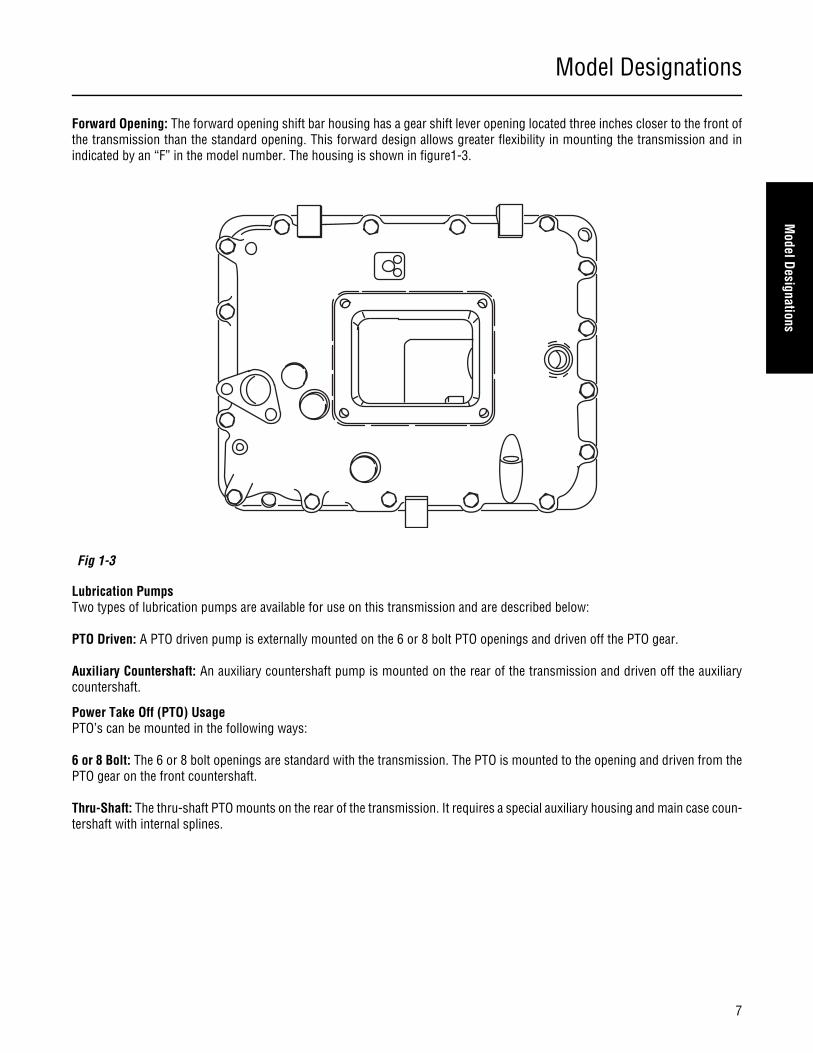
Forward Opening: The forward opening shift bar housing has a gear shift lever opening located three inches closer to the front ofthe transmission than the standard opening. This forward design allows greater flexibility in mounting the transmission and inindicated by an “F” in the model number. The housing is shown in figure1-3.
Lubrication PumpsTwo types of lubrication pumps are available for use on this transmission and are described below:
PTO Driven: A PTO driven pump is externally mounted on the 6 or 8 bolt PTO openings and driven off the PTO gear.
Auxiliary Countershaft: An auxiliary countershaft pump is mounted on the rear of the transmission and driven off the auxiliarycountershaft.
Power Take Off (PTO) UsagePTO’s can be mounted in the following ways:
6 or 8 Bolt: The 6 or 8 bolt openings are standard with the transmission. The PTO is mounted to the opening and driven from thePTO gear on the front countershaft.
Thru-Shaft: The thru-shaft PTO mounts on the rear of the transmission. It requires a special auxiliary housing and main case coun-tershaft with internal splines.
Fig 1-3
Lubrication
8
Lubrication SpecificationsNote: For a list of Eaton Approved Synthetic Lubricants, see TCMT-0021 or call 1-800-826-HELP (4357).
Note: The use of lubricants not meeting these requirements will affect warranty coverage.
Note: Additives and friction modifiers must not be introduced. Never mix engine oils and gear oils in the same transmission.
Transmission filters should be changed during regular lube intervals. Inspection of the transmission filter should be conduct-ed during preventive maintenance checks for damage or corrosion. Replace as necessary.
Buy from a reputable dealerFor a complete list of approved and reputable dealers, write to: Eaton Corporation, Worldwide Marketing Services, P.O. Box 4013,Kalamazoo, MI 49003
Transmission Operating AnglesIf the transmission operating angle is more than 12 degrees, improper lubrication will occur. The operating angle is the transmis-sion mounting angle in the chassis plus the percent of upgrade (expressed in degrees). For operating angles over 12 degrees, thetransmission must be equipped with an oil pump or cooler kit to insure proper lubrication.
Operating Temperatures with Oil CoolersThe transmission must not be operated consistently at temperatures above 250° F. Operation at temperatures above 250°F[121°C] causes loaded gear tooth temperatures to exceed 350°F [177°C] which will ultimately destroy the heat treatment of thegears. If the elevated temperature is associated with an unusual operating condition that will reoccur, a cooler should be added,or the capacity of the existing cooling system increased.The following conditions in any combination can cause operating temperatures of over 250° F [121°C]:
• Operating consistently at slow speed.
• High ambient temperatures.
• Restricted air flow around transmission.
• Use of engine retarder.
• High horsepower operation.
Note: Transmission coolers must be used to reduce the operating temperatures when the above conditions are encountered.
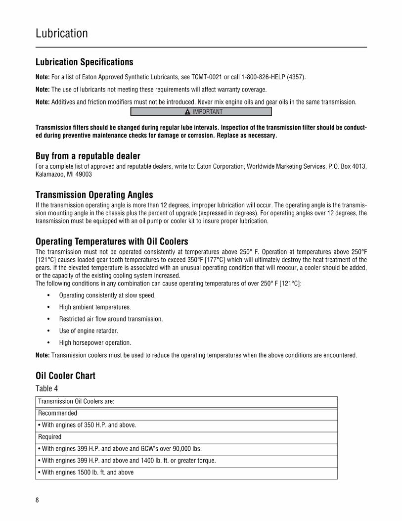
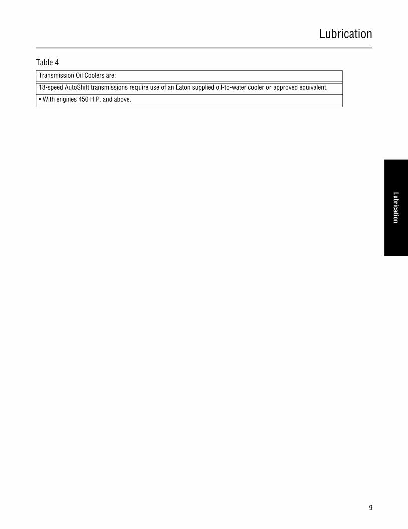
Oil Cooler ChartTable 4
Transmission Oil Coolers are:
Recommended
• With engines of 350 H.P. and above.
Required
• With engines 399 H.P. and above and GCW’s over 90,000 lbs.
• With engines 399 H.P. and above and 1400 lb. ft. or greater torque.
• With engines 1500 lb. ft. and above
IMPORTANT
Lubrication
9
Lubrication
18-speed AutoShift transmissions require use of an Eaton supplied oil-to-water cooler or approved equivalent.
• With engines 450 H.P. and above.
Table 4
Transmission Oil Coolers are:
Lubrication
10
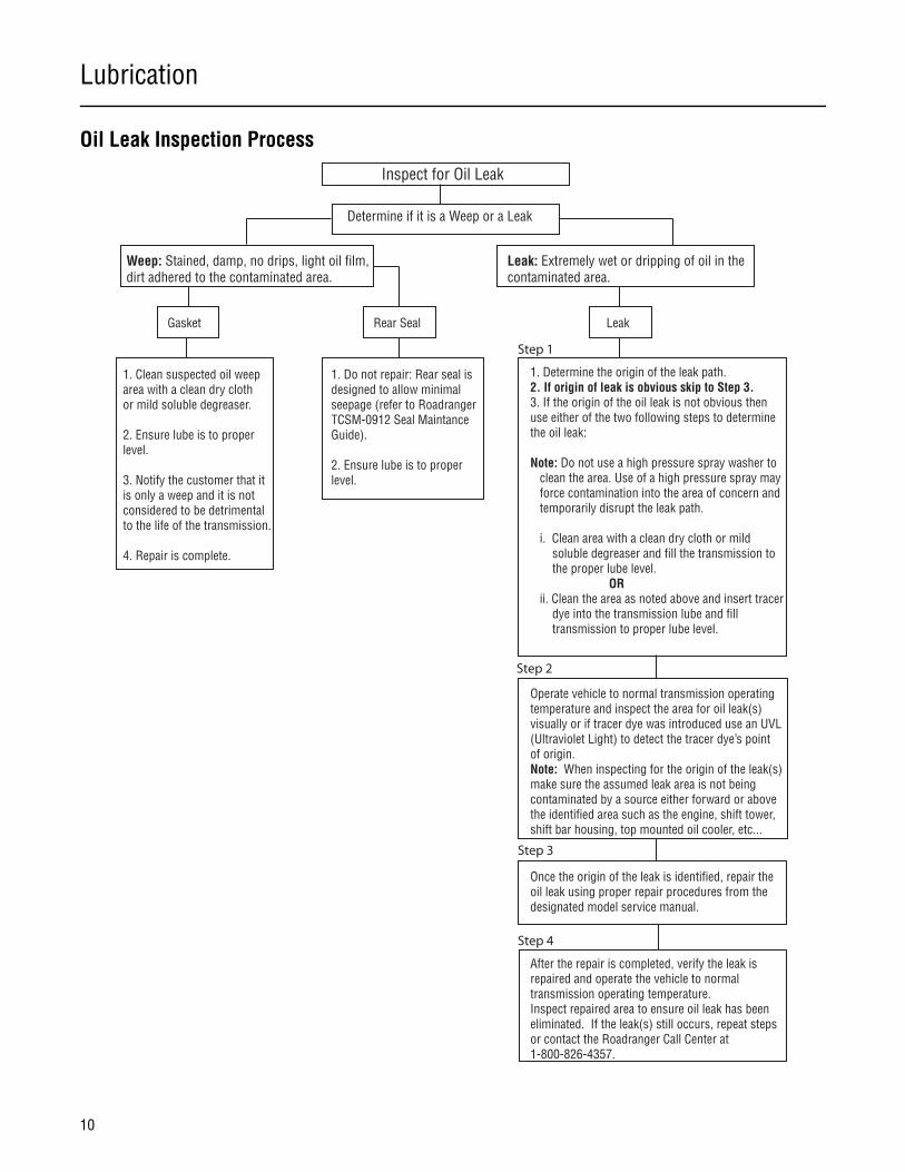
Oil Leak Inspection Process
Inspect for Oil Leak
Determine if it is a Weep or a Leak
Weep: Stained, damp, no drips, light oil film,dirt adhered to the contaminated area.
Leak: Extremely wet or dripping of oil in thecontaminated area.
Gasket Rear Seal Leak
1. Clean suspected oil weeparea with a clean dry clothor mild soluble degreaser.
2. Ensure lube is to properlevel.
3. Notify the customer that it is only a weep and it is notconsidered to be detrimentalto the life of the transmission.
4. Repair is complete.
1. Do not repair: Rear seal is designed to allow minimalseepage (refer to RoadrangerTCSM-0912 Seal MaintanceGuide).
2. Ensure lube is to properlevel.
1. Determine the origin of the leak path.2. If origin of leak is obvious skip to Step 3.3. If the origin of the oil leak is not obvious then use either of the two following steps to determine the oil leak:
Note: Do not use a high pressure spray washer to clean the area. Use of a high pressure spray may force contamination into the area of concern and temporarily disrupt the leak path. i. Clean area with a clean dry cloth or mild soluble degreaser and fill the transmission to the proper lube level. OR ii. Clean the area as noted above and insert tracer dye into the transmission lube and fill transmission to proper lube level.
Operate vehicle to normal transmission operating temperature and inspect the area for oil leak(s) visually or if tracer dye was introduced use an UVL (Ultraviolet Light) to detect the tracer dye’s point of origin.Note: When inspecting for the origin of the leak(s) make sure the assumed leak area is not being contaminated by a source either forward or above the identified area such as the engine, shift tower, shift bar housing, top mounted oil cooler, etc...
Once the origin of the leak is identified, repair the oil leak using proper repair procedures from the designated model service manual.
After the repair is completed, verify the leak is repaired and operate the vehicle to normaltransmission operating temperature.Inspect repaired area to ensure oil leak has been eliminated. If the leak(s) still occurs, repeat steps or contact the Roadranger Call Center at 1-800-826-4357.
Step 1
Step 2
Step 3
Step 4
Transmission Operation and Theory
11
Transmission Operation and
Theory
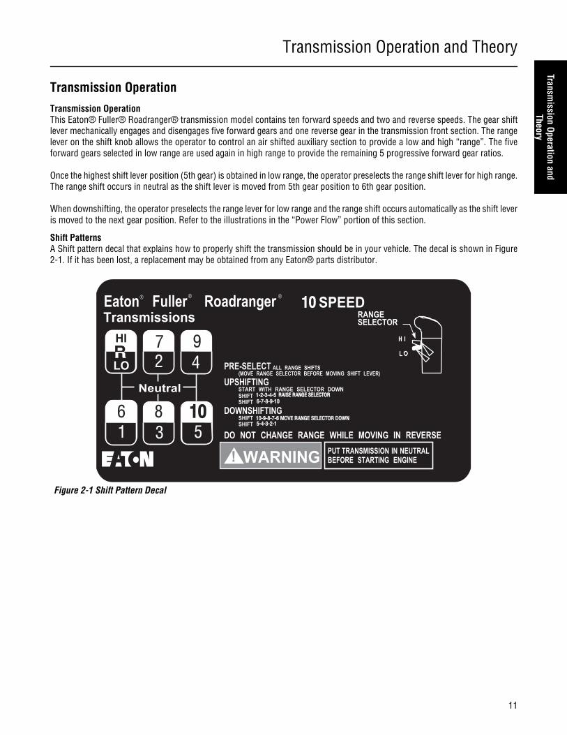
Transmission OperationTransmission OperationThis Eaton® Fuller® Roadranger® transmission model contains ten forward speeds and two and reverse speeds. The gear shiftlever mechanically engages and disengages five forward gears and one reverse gear in the transmission front section. The rangelever on the shift knob allows the operator to control an air shifted auxiliary section to provide a low and high “range”. The fiveforward gears selected in low range are used again in high range to provide the remaining 5 progressive forward gear ratios.
Once the highest shift lever position (5th gear) is obtained in low range, the operator preselects the range shift lever for high range.The range shift occurs in neutral as the shift lever is moved from 5th gear position to 6th gear position.
When downshifting, the operator preselects the range lever for low range and the range shift occurs automatically as the shift leveris moved to the next gear position. Refer to the illustrations in the “Power Flow” portion of this section.
Shift PatternsA Shift pattern decal that explains how to properly shift the transmission should be in your vehicle. The decal is shown in Figure2-1. If it has been lost, a replacement may be obtained from any Eaton® parts distributor.
Figure 2-1 Shift Pattern Decal
1010
1-2-3-4-51-2-3-4-5 RAISE RANGE SELECTORRAISE RANGE SELECTOR
10-9-8-7-6 MOVE RANGE SELECTOR DOWN10-9-8-7-6 MOVE RANGE SELECTOR DOWN5-4-3-2-15-4-3-2-1
61 3
2 4
8
97
10105
6-7-8-9-106-7-8-9-10
Transmission Operation and Theory
12
Operating InstructionsInitial Start - Up
Before starting a vehicle always be seated in the driver’s seat, move the shift lever to neutral, and set the parking brakes.
Before moving a vehicle, make sure you understand the shift pattern configuration.
1. Make sure the shift lever is in neutral and the parking brakes are set.
2. Turn on the key switch, and start the engine.
3. Allow the vehicle air pressure to build to the correct level. Refer to your “Operator and Service Manual” supplied with thetruck.
4. Apply the service brakes.
5. Release the parking brakes on the vehicle.
6. Make sure the Range Selector is down in the low range position as shown below in Figure 2-2.
7. Depress the clutch pedal to the floor.
8. Move the shift lever to the desired initial gear.
9. Slowly release the clutch pedal and apply the accelerator.
Figure 2-2
WARNING
CAUTION
Transmission Operation and Theory
13
Transmission Operation and
Theory
Upshifting
CAUTION: Never move the Range Selector with the shift lever in neutral while the vehicle is moving.
1. Move the shift lever, double-clutching, to the next desired gear position in low range.
Range shift - low to high Range (5th to 6th)
2. When in last gear position for low range and ready for the next upshift, pull up the Range Selector and move the shiftlever, double-clutching, to the next higher speed position according to your shift pattern. As the shift lever passesthrough neutral, the transmission will automatically shift from low to high range.
Note: If after attempting a range shift to high, the transmission remains in neutral with the shift lever in gear, the range synchro-nizer protection device may deactivated. Move the shift lever into neutral to allow the range shift to complete, and then movethe shift lever back into gear.
3. Continue upshifting, double-clutching, to the next desired gear position in high range
Downshifting1. Move the shift lever, double-clutching, to the next desired gear position in high range
Range shift from High Range to Low Range (6th to 5th)
2. While in 6th and ready for the next downshift, preselect low range, and push the Range Selector down.
3. Move the shift lever, double-clutching, to the next desired gear position in low range. As the shift lever passes throughneutral, the transmission automatically shifts from high range to low range.
4. Continue downshifting, double-clutching, to the next desired gear position in low range
Double - Clutching Procedure1. Depress the pedal to disengage the clutch.
2. Move the shift lever to neutral.
3. Release the pedal to engage the clutch.*
a. Upshifts-decelerate engine until engine RPM and road speed match.
b. Downshifts-accelerate engine until engine RPM and road speed match.
4. Quickly depress the pedal to disengage the clutch and move the shift lever to the next gear speed position.
5. Release the pedal to engage the clutch.
Note: * By engaging the clutch with the shift lever in the neutral position, the operator is able to control the mainshaft gear RPMsince it is regulated by engine RPM. This procedure allows the operator to speed up or slow down the mainshaft gearing toproperly match the desired gear speed and output shaft speed.
Transmission Operation and Theory
14
Additional Operating InformationPreselectIMPORTANT: Always preselect all range shifts when upshifting or downshifting. Preselection requires that the Range Selector ismoved to the needed position before starting the lever shift.
Preselected range shifts are completed automatically as the lever is moved through neutral and into the next gear. Preselecting allrange shifts prevents damage to the transmission and provides for smoother shifts.
SynchroSaver™The transmission contains a range synchronizer protection device to prevent damage to the high range synchronizer. If the shiftlever engages a front section gear prior to completion of the air shift into high range, the range synchronizer remains in neutral,preventing damage to the range synchronizer. If this neutral condition occurs, the operator must shift the lever to neutral and thenback into gear to complete the range shift.
Clutch Brake (Used with pull-type clutches)The Clutch Brake is applied by fully depressing the clutch pedal to the floor board. When applied, the brake slows down and canstop the transmission front box gearing. It is a disc-type brake incorporated into the clutch and transmission drive gear assem-blies. Never use the Clutch Brake when upshifting or downshifting. Use only for initial gear engagement when the vehicle is stand-ing still.
Countershaft Brake (Used with push-type clutches)The control button is mounted on the shift lever just below the shift knob. To operate the brake, disengage the clutch, press downthe control button, and shift into 1st or reverse. This is an air operated mechanical brake which slows down the transmission gear-ing by forcing a piston against the countershaft PTO gear.
Note: Never use the Countershaft Brake when upshifting or downshifting. Use only for initial gear engagement when the vehicleis standing still.
Driver Instruction Booklet
Complete operation instruction can be found in the Drive Instruction Booklet TRDR-0515.
Tools
15
Tools
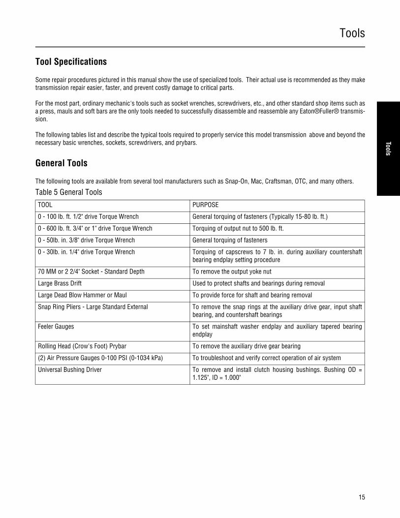
Tool Specifications
Some repair procedures pictured in this manual show the use of specialized tools. Their actual use is recommended as they maketransmission repair easier, faster, and prevent costly damage to critical parts.
For the most part, ordinary mechanic's tools such as socket wrenches, screwdrivers, etc., and other standard shop items such asa press, mauls and soft bars are the only tools needed to successfully disassemble and reassemble any Eaton®Fuller® transmis-sion.
The following tables list and describe the typical tools required to properly service this model transmission above and beyond thenecessary basic wrenches, sockets, screwdrivers, and prybars.
General Tools
The following tools are available from several tool manufacturers such as Snap-On, Mac, Craftsman, OTC, and many others.
Table 5 General Tools
TOOL PURPOSE
0 - 100 lb. ft. 1/2" drive Torque Wrench General torquing of fasteners (Typically 15-80 lb. ft.)
0 - 600 lb. ft. 3/4" or 1" drive Torque Wrench Torquing of output nut to 500 lb. ft.
0 - 50lb. in. 3/8" drive Torque Wrench General torquing of fasteners
0 - 30lb. in. 1/4" drive Torque Wrench Torquing of capscrews to 7 lb. in. during auxiliary countershaftbearing endplay setting procedure
70 MM or 2 2/4" Socket - Standard Depth To remove the output yoke nut
Large Brass Drift Used to protect shafts and bearings during removal
Large Dead Blow Hammer or Maul To provide force for shaft and bearing removal
Snap Ring Pliers - Large Standard External To remove the snap rings at the auxiliary drive gear, input shaftbearing, and countershaft bearings
Feeler Gauges To set mainshaft washer endplay and auxiliary tapered bearingendplay
Rolling Head (Crow's Foot) Prybar To remove the auxiliary drive gear bearing
(2) Air Pressure Gauges 0-100 PSI (0-1034 kPa) To troubleshoot and verify correct operation of air system
Universal Bushing Driver To remove and install clutch housing bushings. Bushing OD =1.125", ID = 1.000"

Tools
16
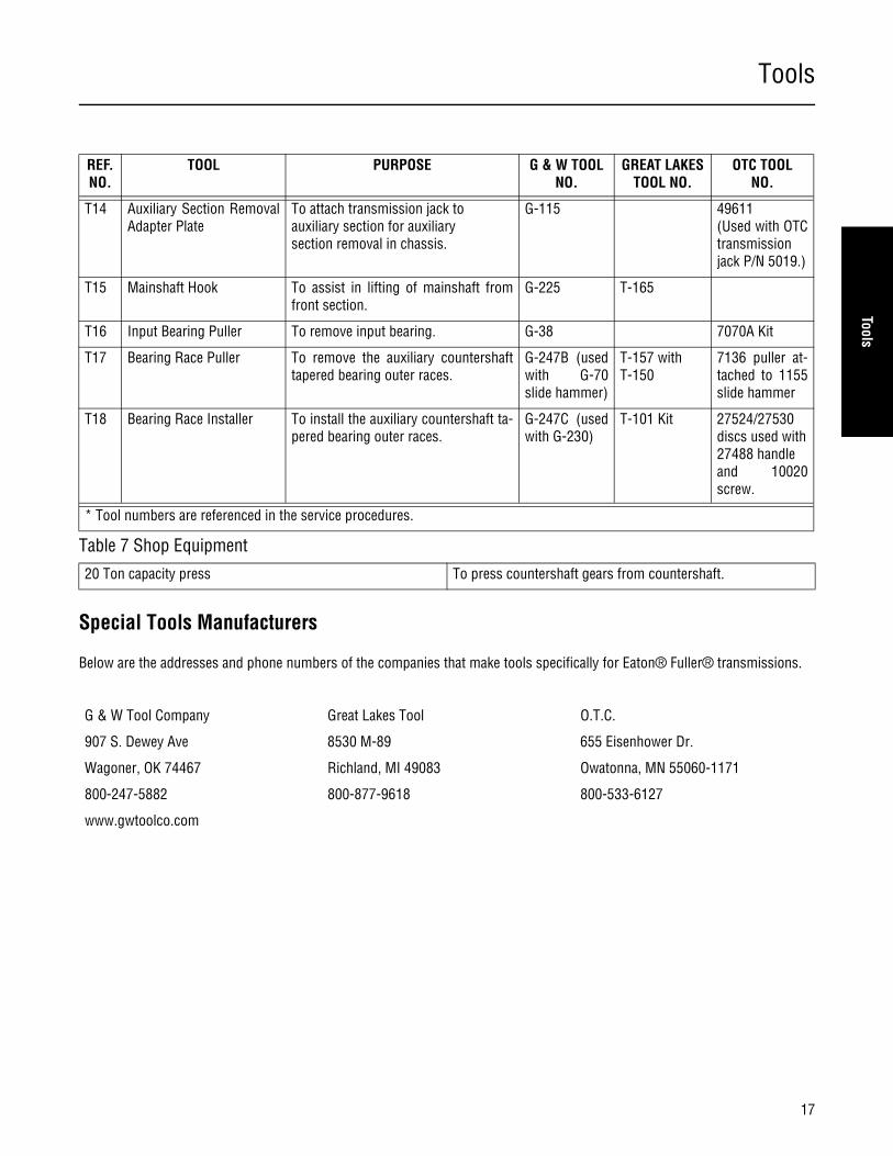
The following special tools are designed for this Eaton®Fuller® transmission. The addresses and phone numbers of the tool sup-pliers are listed after the table. This list is provided as a convenience to our customers. These tools are manufactured by indepen-dent companies with no relationship to Eaton®Fuller®. Eaton®Fuller® does not warrant the fit or function of the listed tools. Toobtain the tools, contact the tool supplier directly.
REF.NO.
TOOL PURPOSE G & W TOOL NO.
GREAT LAKESTOOL NO.
OTC TOOLNO.
T1 Output Yoke Puller May be required to remove a rustedoutput yoke.
SP-450 7075
T2 Auxiliary Section Hanger To support, or hang, the auxiliary sec-tion in the horizontal position.
G-40 T-125 5061
T3 AuxiliaryCountershaft Support and Shim Tool
To hold the auxiliary countershafts inposition while installing the auxiliarysection in the horizontal position. Alsoto simplify the checking and setting of the auxiliarycountershaft bearing endplay.
G-250(can also useG-251)
T-311 5062
T4 Shift Lever SpringInstallation Tool(Tension Spring Driver)
To install the shift tower tensionspring.
G-116 T-170
T5 Slide Hammer To remove the output seal and reverseidler shafts. Requires 1/2"-13 threads.(Optional, idler shaft can be driven outfrom front.)
G-70 (with g-247D for Rev.Idler removal)
T-150 (with T-151 metricadapter)
1155 SlideHammer / 8007 1/2" -13Adapter
T6 Bearing Puller To remove front section countershaftbearings.
G-246 T-2 7070A Kit
T7 Bearing Driver To install front section countershaftbearings
G-230 T-101 Kit orT-120 with T-120A adapter
T8 Bearing Driver To install the front countershaft rearbearings
G-230 T-101 Kit
T9 CountershaftSupport Tools (2)
To support and locate the front section countershafts during bearing removal and installation.
G-54 T-132 7109
T10 Input Bearing Driver To install input bearing on input shaft. G-35 T-120 5066 (2" shaft)
T11 Bearing Puller To remove the auxiliary countershafttapered bearings.
G-247 or G-247A
1123 / 927
T12 Bearing Driver To install the auxiliary countershaft ta-pered bearings.
G-230 T-101 Kit
T13 Output Seal Removal Tool To remove the output seal in chassis. Can use slide hammer.
Use 27315hook with 1155slide hammer
* Tool numbers are referenced in the service procedures.
Tools
17
Tools
Special Tools Manufacturers
Below are the addresses and phone numbers of the companies that make tools specifically for Eaton® Fuller® transmissions.
T14 Auxiliary Section RemovalAdapter Plate
To attach transmission jack to auxiliary section for auxiliary section removal in chassis.
G-115 49611(Used with OTCtransmissionjack P/N 5019.)
T15 Mainshaft Hook To assist in lifting of mainshaft fromfront section.
G-225 T-165
T16 Input Bearing Puller To remove input bearing. G-38 7070A Kit
T17 Bearing Race Puller To remove the auxiliary countershafttapered bearing outer races.
G-247B (usedwith G-70slide hammer)
T-157 with T-150
7136 puller at-tached to 1155slide hammer
T18 Bearing Race Installer To install the auxiliary countershaft ta-pered bearing outer races.
G-247C (usedwith G-230)
T-101 Kit 27524/27530discs used with27488 handleand 10020screw.
Table 7 Shop Equipment
20 Ton capacity press To press countershaft gears from countershaft.
G & W Tool Company Great Lakes Tool O.T.C.
907 S. Dewey Ave 8530 M-89 655 Eisenhower Dr.
Wagoner, OK 74467 Richland, MI 49083 Owatonna, MN 55060-1171
800-247-5882 800-877-9618 800-533-6127
www.gwtoolco.com
REF.NO.
TOOL PURPOSE G & W TOOL NO.
GREAT LAKESTOOL NO.
OTC TOOLNO.
* Tool numbers are referenced in the service procedures.
Tools
18
Eaton Aftermarket Parts
The following tools are available through Eaton Aftermarket Parts. To obtain any of the tools listed, contact your local Eaton partsdistributor.
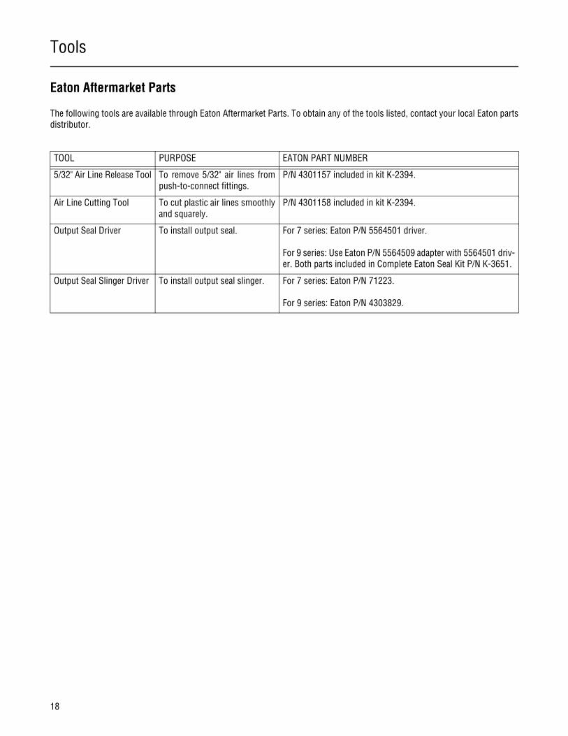
TOOL PURPOSE EATON PART NUMBER
5/32" Air Line Release Tool To remove 5/32" air lines frompush-to-connect fittings.
P/N 4301157 included in kit K-2394.
Air Line Cutting Tool To cut plastic air lines smoothlyand squarely.
P/N 4301158 included in kit K-2394.
Output Seal Driver To install output seal. For 7 series: Eaton P/N 5564501 driver.
For 9 series: Use Eaton P/N 5564509 adapter with 5564501 driv-er. Both parts included in Complete Eaton Seal Kit P/N K-3651.
Output Seal Slinger Driver To install output seal slinger. For 7 series: Eaton P/N 71223.
For 9 series: Eaton P/N 4303829.
Transmission Overhaul Procedures-Bench Service
19
Transmission Overhaul
Procedures-Bench Service
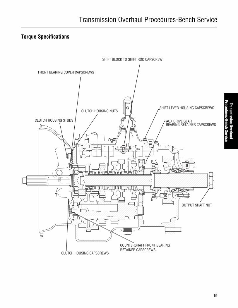
Torque Specifications
OUTPUT SHAFT NUT
AUX DRIVE GEAR BEARING RETAINER CAPSCREWS
SHIFT LEVER HOUSING CAPSCREWS
SHIFT BLOCK TO SHIFT ROD CAPSCREW
COUNTERSHAFT FRONT BEARING RETAINER CAPSCREWS
CLUTCH HOUSING CAPSCREWS
FRONT BEARING COVER CAPSCREWS
CLUTCH HOUSING STUDS
CLUTCH HOUSING NUTS
Transmission Overhaul Procedures-Bench Service
20
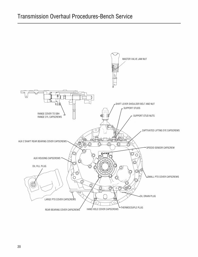
MASTER VALVE JAM NUT
SUPPORT STUDS
SUPPORT STUD NUTS
CAPTIVATED LIFTING EYE CAPSCREWS
SPEEDO SENSOR CAPSCREW
SMALL PTO COVER CAPSCREWS
OIL DRAIN PLUG
THERMOCOUPLE PLUGREAR BEARING COVER CAPSCREWS HAND HOLE COVER CAPSCREWS
LARGE PTO COVER CAPSCREWS
AUX C'SHAFT REAR BEARING COVER CAPSCREWS
AUX HOUSING CAPSCREWS
OIL FILL PLUG
RANGE COVER TO SBH RANGE CYL CAPSCREWS
SHIFT LEVER SHOULDER BOLT AND NUT

Power Flow
21
General Information
Power Flow Diagrams
An understanding of the engine’s power flow through a transmission in each particular gear will assist the technician in trouble-shooting and servicing a transmission.
The Eaton Fuller Roadranger transmission can be thought of as two separate “transmissions” combined into one unit. The first“transmission” or front section contains six gear sets which are shifted with the gear shift lever. The second “transmission” calledthe auxiliary section, contains two gear sets and is shifted with air pressure.
Note: This transmission is referred to as a constant mesh type transmission. When in operation, all gears are turning even thoughonly some of them are transferring power.
Figure 2-3 below shows the transmission with the main components called out. Note that the transmission is in the neutral posi-tion because the sliding clutches are all in their center positions and not engaged is any gears.
Figure 2-3. Transmission Components Important for Understanding Power Flow
Front Section
Input Shaft
Main Drive Gear
Sliding Clutch Countershaft
Mainshaft Gear
Auxiliary Countershaft
Range Sliding Clutch
Auxiliary MainshaftReduction Gear
Output Shaft(Auxiliary Mainshaft)
Auxiliary Drive GearAuxiliary Section
Power Flow
22
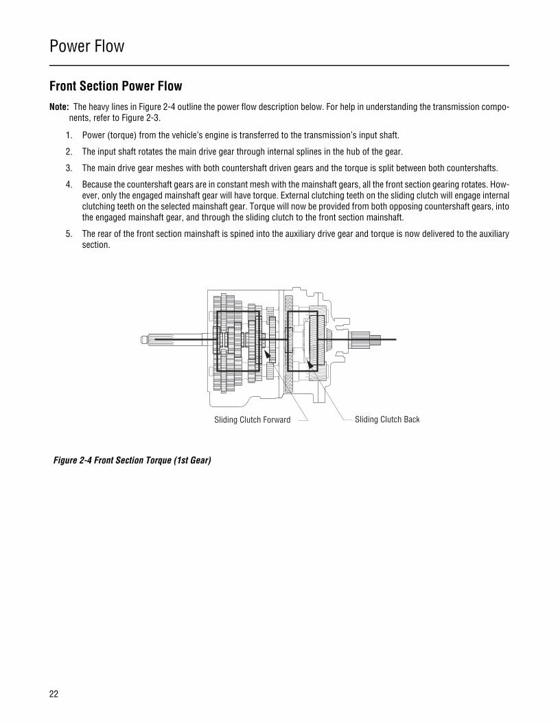
Front Section Power FlowNote: The heavy lines in Figure 2-4 outline the power flow description below. For help in understanding the transmission compo-
nents, refer to Figure 2-3.
1. Power (torque) from the vehicle’s engine is transferred to the transmission’s input shaft.
2. The input shaft rotates the main drive gear through internal splines in the hub of the gear.
3. The main drive gear meshes with both countershaft driven gears and the torque is split between both countershafts.
4. Because the countershaft gears are in constant mesh with the mainshaft gears, all the front section gearing rotates. How-ever, only the engaged mainshaft gear will have torque. External clutching teeth on the sliding clutch will engage internalclutching teeth on the selected mainshaft gear. Torque will now be provided from both opposing countershaft gears, intothe engaged mainshaft gear, and through the sliding clutch to the front section mainshaft.
5. The rear of the front section mainshaft is spined into the auxiliary drive gear and torque is now delivered to the auxiliarysection.
Figure 2-4 Front Section Torque (1st Gear)
Sliding Clutch Forward Sliding Clutch Back
Power Flow
23
General Information
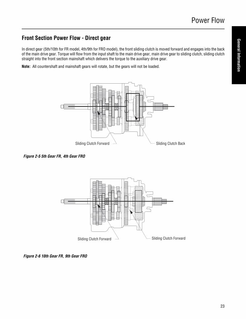
Front Section Power Flow - Direct gear
In direct gear (5th/10th for FR model, 4th/9th for FRO model), the front sliding clutch is moved forward and engages into the backof the main drive gear. Torque will flow from the input shaft to the main drive gear, main drive gear to sliding clutch, sliding clutchstraight into the front section mainshaft which delivers the torque to the auxiliary drive gear.
Note: All countershaft and mainshaft gears will rotate, but the gears will not be loaded.
Figure 2-5 5th Gear FR, 4th Gear FRO
Figure 2-6 10th Gear FR, 9th Gear FRO
Sliding Clutch Forward Sliding Clutch Back
Sliding Clutch Forward Sliding Clutch Forward
Power Flow
24
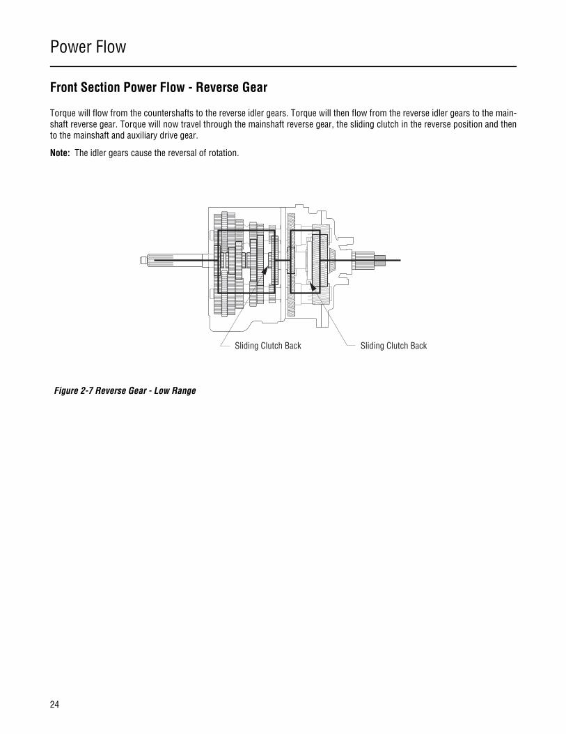
Front Section Power Flow - Reverse Gear
Torque will flow from the countershafts to the reverse idler gears. Torque will then flow from the reverse idler gears to the main-shaft reverse gear. Torque will now travel through the mainshaft reverse gear, the sliding clutch in the reverse position and thento the mainshaft and auxiliary drive gear.
Note: The idler gears cause the reversal of rotation.
Figure 2-7 Reverse Gear - Low Range
Sliding Clutch Back Sliding Clutch Back
Power Flow
25
General Information
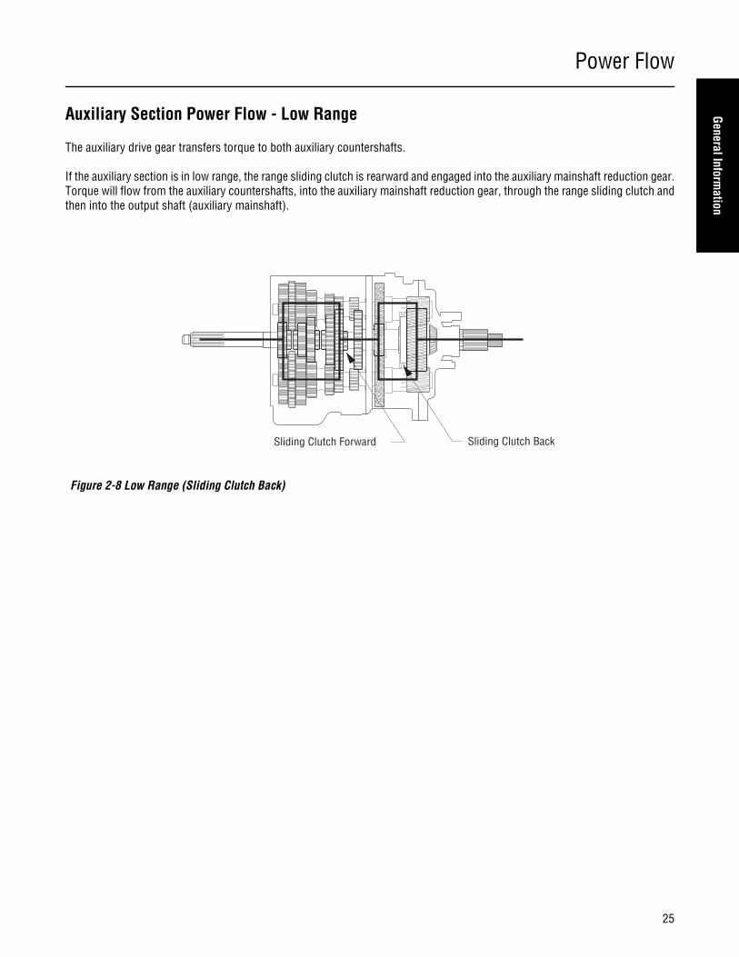
Auxiliary Section Power Flow - Low Range
The auxiliary drive gear transfers torque to both auxiliary countershafts.
If the auxiliary section is in low range, the range sliding clutch is rearward and engaged into the auxiliary mainshaft reduction gear.Torque will flow from the auxiliary countershafts, into the auxiliary mainshaft reduction gear, through the range sliding clutch andthen into the output shaft (auxiliary mainshaft).
Figure 2-8 Low Range (Sliding Clutch Back)
Sliding Clutch Forward Sliding Clutch Back
Power Flow
26
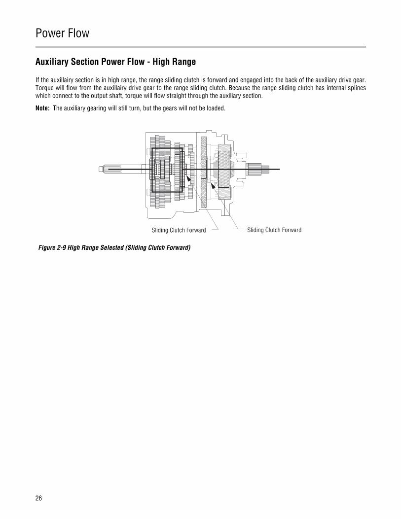
Auxiliary Section Power Flow - High Range
If the auxillairy section is in high range, the range sliding clutch is forward and engaged into the back of the auxiliary drive gear.Torque will flow from the auxillairy drive gear to the range sliding clutch. Because the range sliding clutch has internal splineswhich connect to the output shaft, torque will flow straight through the auxiliary section.
Note: The auxiliary gearing will still turn, but the gears will not be loaded.
Figure 2-9 High Range Selected (Sliding Clutch Forward)
Sliding Clutch Forward Sliding Clutch Forward
Power Flow
27
General Information
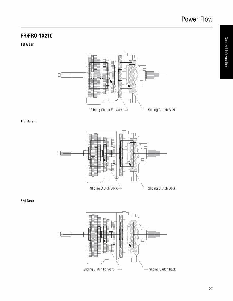
FR/FRO-1X210 1st Gear
2nd Gear
3rd Gear
Sliding Clutch Forward Sliding Clutch Back
Sliding Clutch Back Sliding Clutch Back
Sliding Clutch Forward Sliding Clutch Back

Power Flow
28
4th Gear-FR/Direct Drive Transmission
5th Gear- FRO/Overdrive Transmission
5th Gear- FR/Direct Drive Transmission
4th Gear FRO/Overdrive Transmission
6th Gear
Sliding Clutch Back Sliding Clutch Back
Sliding Clutch Forward Sliding Clutch Back
Sliding Clutch Forward Sliding Clutch Forward

Power Flow
29
General Information
7th Gear
8th Gear
9th Gear-FR/Direct Drive Transmission
10th Gear-FRO/Overdrive Transmission
Sliding Clutch Back Sliding Clutch Forward
Sliding Clutch Forward Sliding Clutch Forward
Sliding Clutch Back Sliding Clutch Forward

Power Flow
30
10thGear-FR/Direct Drive Transmission
9th Gear-FRO/Overdrive Transmission
Sliding Clutch Forward Sliding Clutch Forward
Air System Troubleshooting
31
General Information
Air System Troubleshooting
The symptoms listed below are covered on the following pages. Before beginning any of those troubleshooting procedures, placethe transmission in neutral and move the range selection lever from low to high. Listen for any constant air leak from the shiftknob, air module base (exhaust), or transmission breather. If a constant leak is heard, go to that particular leak troubleshootingprocedure first.
If you do not see the symptom you need to correct, refer to the General Troubleshooting chart.
Symptom
• Air Leak from Air Module Base (Exhaust Leak)
• No or Slow Range Shift into High (Shift into low range is good)
• No or Slow Range Shift into Low (Shift into high range is good)
• Constant Air Leak from Shift Knob
• Range Shifts in Gear
• Air Leak from Transmission Breather or Transmission Case is Pressurized
Note: Use the air system troubleshooting procedures for part replacement only if the symptom can be duplicated. If the problemis intermittent, parts that are not defective could be replaced.
Note: During all testing, the vehicle air pressure must be greater than 90 PSI (620 kPa). If during testing the pressure falls below90 PSI (620 kPa), make sure the transmission is in neutral, start the engine and let the pressure build to governor cutoff.After the pressure reaches the governor cutoff, continue testing. The pressure is critical if the vehicle is equipped with a ve-hicle air system Pressure Protection Valve that would shut off the air supply to certain air circuits if the system pressuredropped below a preset level.
Note: A 0-150 PSI (0-1034 kPa) air gauge with a 1/16" male pipe thread fitting attachment is required for some of the test proce-dures.
Note: Regulated air pressure is 75 to 85 PSI (517 - 586 kPa).
Prior to removing the air module, exhaust the air from it. Failure to exhaust the air module may result in personal injury ordamage to parts from the sudden release of air.
Use care when removing the test port pipe plugs. If air pressure is present on the plug, it can become a projectile duringremoval. When removing the “L” plug or “H” plug, pressure can be shut off by selecting the opposite range mode. If remov-ing the “F” plug, exhaust the air to the module inlet.
WARNING

Air System Troubleshooting
32
Air System Symptom - Air leak from Module Base (Exhaust)
Short bursts of air leakage from the module base (exhaust) are normal as the range system is shifted. The module base is definedas both the interface of the module cover and module base and the extreme underside of the module. Leakage is a problem whenit is audible and constant. Air leakage from the module base may result from either a defective air module or a defective rangepiston. The following procedure will identify the defective component.
Test Procedure:1. Check for air leakage from the module base (exhaust) in each of the four following conditions. (Make sure the range is shiftedwhen the shift lever is shifted into neutral.)
a. Range selection lever in Low and shift lever in neutral.
b. Range selection lever in Low and shift lever in gear.
c. Range selection lever in High and shift lever in neutral.
d. Range selection lever in High and shift lever in gear.
Record the findings (constant leak or no leak) in the following table.
2. If the information you recorded at step 1 matches one of the following tables, replace the air module. If your table does notmatch either of the tables, it will be necessary to isolate and test the air module separately, continue to step 3.
Failure to exhaust the air pressure may cause personal injury or damage to parts.
3. Exhaust the air pressure from the air module. To do so, the vehicle’s air tanks may need to be exhausted.
4. Leaving all air lines connected to the module, remove the four capscrews attaching the air module to the shift bar housing. Liftthe air module and tilt it to gain access to the two air holes at the underside on the rear capscrew location. Do not damage or losethe two o-rings used to seal the holes.
5. Block off the air ports on the underside of the module. Use a piece of gasket material or rubber material to seal the bottom ofthe module as shown in Figure 4-4 “Air System Nomenclature”.
6. Repressurize the air module with an inlet supply pressure of over 90 PSI (620 kPa). To repressurize the air module, the vehiclemay need to be started and air pressure allowed to build up.
Range Selector in LOW Range Selector in HIGH
Lever in Neutral
Lever in Gear
Range Selector in LOW Range Selector in HIGH
Lever in Neutral No Leak Constant Leak
Lever in Gear No Leak Constant Leak
Range Selector in LOW Range Selector in HIGH
Lever in Neutral Constant Leak Constant Leak
Lever in Gear Constant Leak Constant Leak
WARNING

Air System Troubleshooting
33
General Information
7. Check for air leakage in both high and low range. If air continues to leak constantly from the exhaust, the air module is defective.If air does not leak, a range cylinder piston or piston seal failure has occurred. Remove the shift bar housing to gain access to therange shift cylinder.
Air System Symptom - No or Slow Range Shift into High (Shift into Low Range is Good)
This transmission contains a SynchroSaver feature to protect the high range synchronizer. When high range is selected and a frontsection gear is engaged, air pressure is supplied to both sides of the range piston, which reduces synchronizer force. Therefore,if the driver engages a front section gear before the high range synchronizer engages, the high range synchronizer will remain inneutral. When a front section gear engages before the synchronizer shift completes, the driver must shift the lever back to neutralto allow the high range synchronizer to complete its shift. Once the range shift is complete, the driver can complete the front sec-tion shift.
If the high range synchronizer hangs up or is slow to synchronize, the front section may engage first. The driver complaint will bethat the transmission “neutralizes” on a shift to high range. If this condition occurs, perform the following test of the air systemto eliminate the air system as the source of the problem. If the air system performs properly, then the problem is internal to thetransmission range synchronizer system.
Note: The driver must preselect all range shifts.
Note: If a capscrew or stud is installed too far into the right side (air module side) rear support hole, the fastener can extend toofar into the transmission. The fastener may contact the range yoke and bind the range synchronizer assembly during therange shift.
Test Procedure1. Check the shift knob operation.
On the shift knob, remove the screws holding the plastic skirt. Slide the skirt down and out of the way. Move the range selectionlever up into high range. Disconnect the black line connected to the “P” port on the knob.
2. Test the regulator pressure. (Regulator pressure should be between 75 and 85 PSI (517-586 kPa))
Reconnect the “P” line at the shift knob. Locate the two small pipe plugs on the rear of the air module. One is labeled “H” the other“L”. (See figure 4-1 “Air System Nomenclature”). Install a 0-150 PSI (0-1034 kPa) air gauge in the port marked “H.”
Note: Prior to removing the pipe plug, turn off the air flow by flipping the range selector down into the low range position. Thetransmission must be in neutral.
Move the range selector up to the high range position and record the pressure on the gauge. Match the pressure to one of thoseon the chart on the next page, and follow the corresponding instructions.
Question Result What to do next
Does air come out of the “P” port on theknob
Yes Repair or replace the knob
No Reconnect the air line to the knob, and con-tinue to the next step.
Question Result What to do Next
What is the air pressure atthe “H” port?
75-85 PSI (517-586 kPa)(to specification)
Continue to the next step

Air System Troubleshooting
34
3. Check the spool valve function.
With the shift lever in neutral, move the range selector from low to high several times. Answer the question on the chart below,and follow the instructions corresponding to the result.
4. Isolate and test the air module. Refer to Figure 4-4 “Air System Nomenclature” to see an example of an isolated air module.
Failure to exhaust the air module may cause personal injury or damage to parts due to the rapid release of air.
Exhaust the air pressure from the air module. To do so, the vehicle air tanks may need to be exhausted. Remove the four capscrewsattaching the air module to the shift bar housing. Lift the air module and tilt it to gain access to the two air holes at the undersideat the rear capscrew location. Do not damage or lose the two O-rings used to seal the holes. Block off the air ports on the undersideof the module. Repressurize the air module with an inlet supply pressure of over 90 PSI (620 kPa). To repressurize the air module,the vehicle may need to be started and the air pressure allowed to build. With the shift lever in neutral and the gauge still in the“H” test port, move the range selection lever from high to low (down) position.
Answer the question on the chart below, and follow the instructions corresponding to the result.
Less than 75 PSI(517 kPa)
Warning: The pipe plug to be removed in this procedure is pressur-ized and could be expelled with great force. To prevent personal in-jury or damage to parts, exhaust the air module before removing theplug, and repressurize the air module after installing the gauge.On the top of the air module, remove the test port pipe plug for fil-tered vehicle air. (Marked “F” as shown in figure 4-1.)Install the test gauge in the “F” port, and check the pressure. If thepressure is less than 90 PSI (620 kPa), repair the vehicle air systemto achieve full vehicle air pressure at the air module inlet, and repeatthe test. If the pressures greater than 90 PSI (620 kPa) and no ex-ternal air leaks were detected from the air module, shift knob, ortransmission, replace the air module.
Greater than 85 PSI(586 kPA)
Replace the air module
Question Result What to do Next
Does the gauge rapidly go from 75-85 PSI (517-586 kPa) in High to 0PSI in Low?
Yes Air system performs properly. Go tostep 5.
No Continue to the next step
Question Result What to do Next
Does the gauge rapidly go from 75-85PSI (517-586 kPa) in High to) PSI inLow?
Yes Continue to the next step.
No Replace the air module.
Question Result What to do Next
WARNING

Air System Troubleshooting
35
General Information
5. Install the air module, and remove the range alignment lock cover (Figure 4-3 “Air System Nomenclature”). Then move therange selection lever from the low to high (up) position. If range now shifts properly, inspect and correct the source of bindingbetween lock cover and range yoke bar. NOTE: To prevent binding, range alignment lock cover capscrews must be tightened whentransmission is in Low Range. If the transmission does not shift properly, continue to Step 6.
6. Remove the auxiliary section and inspect the range synchronizer, range yoke, range yoke bar, range yoke snap ring, range slid-ing clutch, and mating gears for excessive wear, binding, or damage. Repair as necessary. If these components do not need repair,continue to Step 7.
7. Remove the shift bar housing and inspect the range piston, piston bar, and cylinder for excessive wear, binding, or damage.Repair as necessary.
Air System Troubleshooting
36
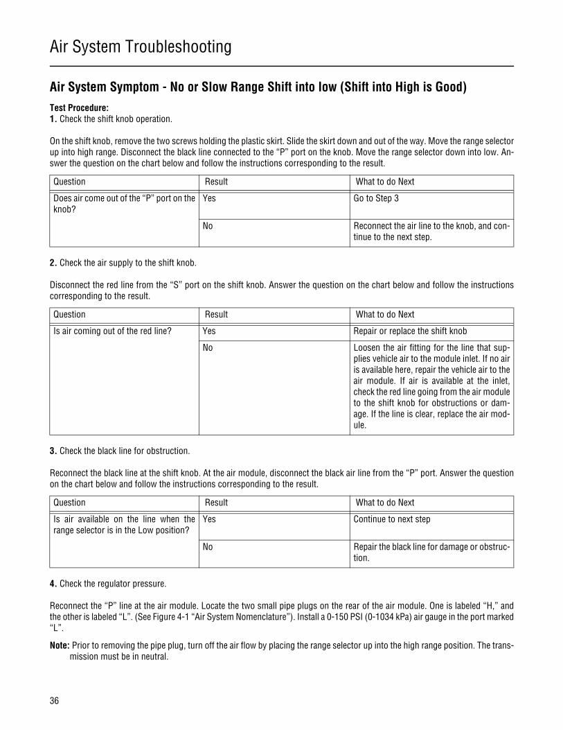
Air System Symptom - No or Slow Range Shift into low (Shift into High is Good)Test Procedure:1. Check the shift knob operation.
On the shift knob, remove the two screws holding the plastic skirt. Slide the skirt down and out of the way. Move the range selectorup into high range. Disconnect the black line connected to the “P” port on the knob. Move the range selector down into low. An-swer the question on the chart below and follow the instructions corresponding to the result.
2. Check the air supply to the shift knob.
Disconnect the red line from the “S” port on the shift knob. Answer the question on the chart below and follow the instructionscorresponding to the result.
3. Check the black line for obstruction.
Reconnect the black line at the shift knob. At the air module, disconnect the black air line from the “P” port. Answer the questionon the chart below and follow the instructions corresponding to the result.
4. Check the regulator pressure.
Reconnect the “P” line at the air module. Locate the two small pipe plugs on the rear of the air module. One is labeled “H,” andthe other is labeled “L”. (See Figure 4-1 “Air System Nomenclature”). Install a 0-150 PSI (0-1034 kPa) air gauge in the port marked“L”.
Note: Prior to removing the pipe plug, turn off the air flow by placing the range selector up into the high range position. The trans-mission must be in neutral.
Question Result What to do Next
Does air come out of the “P” port on theknob?
Yes Go to Step 3
No Reconnect the air line to the knob, and con-tinue to the next step.
Question Result What to do Next
Is air coming out of the red line? Yes Repair or replace the shift knob
No Loosen the air fitting for the line that sup-plies vehicle air to the module inlet. If no airis available here, repair the vehicle air to theair module. If air is available at the inlet,check the red line going from the air moduleto the shift knob for obstructions or dam-age. If the line is clear, replace the air mod-ule.
Question Result What to do Next
Is air available on the line when therange selector is in the Low position?
Yes Continue to next step
No Repair the black line for damage or obstruc-tion.

Air System Troubleshooting
37
General Information
Move the range selector down to the low position and record the pressure on the gauge. Match the air pressure to one of thosedescribed on the chart on the next page, and follow the corresponding instructions.
5. Check the spool valve function.
With the shift lever in neutral, move the range select from low to high several times. Answer the question on the chart below andfollow the instructions corresponding to the result.
6. Isolate the air module from the transmission. Refer to Figure 4-4 “Air System Nomenclature” to see an example of an isolatedair module.
Failure to exhaust the air module may cause personal injury or damage to parts due to the rapid release of air.
Exhaust the air pressure from the air module. To do so, you may have to exhaust the vehicle air. Remove the four capscrews at-taching the air module to the shift bar housing. Lift the air module and tilt it to gain access to the two air holes on the undersideat the rear capscrew location. Do not lose or damage the two small O-rings that seal the holes. Block off the air ports at the un-derside of the module. Repressurize the air module with an inlet supply pressure of over 90 PSI (620 kPa). To repressurize the airmodule, the vehicle may have to be started and the air pressure allowed to build. With the shift lever in neutral and the gauge stillin the “L” test port, move the range selector from low to high (up) position.
Question Result What to do Next
What is the air pressure at the “L” port? 75-85 PSI (517-586 kPa) (To specifica-tion.)
Continue to the next step.
Less than 75 PSI (517 kPa) Warning: The pipe plug to be removed inthis procedure is pressurized and could beexpelled with great force. To prevent per-sonal injury or damage to parts, exhaust theair module before removing the plug, andrepressurize the air module after installingthe gaugeOn the top or the air module, remove thetest port pipe plug for filtered vehicle air.(Marked “F” as shown in figure 4-1 “AirSystem Nomenclature”)Install the test gauge in the “F” port, andcheck the pressure. If the pressure is lessthan 90 PSI (620 kPa), repair the vehicle airsystem to achieve full vehicle air pressure atthe module inlet, and repeat the test. If thepressure is greater than 90 PSI (620spa)and no external air leaks were detected formthe air module, shift knob, or transmission,replace the air module.
Greater than 85 PSI (586 kPa) Replace the air module.
Question Result What to do Next
Does the gauge rapidly go from 75-85PSI (517-586 kPa) in Low to 0 PSI inHigh
Yes Air system performs properly. Go to step 7.
No Continue to the next step.
WARNING
Air System Troubleshooting
38
Answer the question on the chart below, and follow the corresponding instructions.
7. Install the air module, and remove range alignment lock cover (Figure 4-4 “Air System Nomenclature”). Then move the rangeselector from low to high (up) position. If range now shifts properly, inspect and correct source of binding between lock coverand range yoke bar. NOTE: To prevent binding, range alignment lock cover capscrew must be tighten when transmission is in LowRange. If transmission does not shift properly, continue to Step 8.
8. Remove the auxiliary section, and inspect range synchronizer, range yoke, range yoke bar, range yoke snap rings, range slidingclutch, and mating gears for excessive wear, binding, or damage. Repair as necessary. If these components do not need repair,continue to step 9.
9. Remove shift bar housing and inspect range piston, piston bar, and cylinder for excessive wear, binding, or damage. Repair asnecessary.
Question Result What to do Next
Does the gauge rapidly go from 75-85PSI (517-586 kPa) in Low to 0 PSI inHigh
Yes Continue to next step.
No Replace the air module.

Air System Troubleshooting
39
General Information
Air System Symptom - Constant Air Leak from Shift Knob
In normal operation, a burst of air will be exhausted from the shift knob when moving the range selector from low to high range.
If a constant air leak is detected, first check for a leaking fitting. If the leak occurs when both high and low range are selected andthe leak is from the exhaust “E” port on the shift knob. Repair or replace the shift knob.
If the leak only occurs in high range, check for reversed hook up of “P” and “S” air lines. If the air lines are connected properly,repair or replace the shift knob.
Air System Troubleshooting
40
Air System Symptom - Range Shift While Transmission is in Gear
The interlock mechanism allows the driver to move the range selection lever while still in gear (preselect). The range will then shiftwhen the shift lever moves into neutral. If the driver preselects a range shift and the shift occurs while the shift lever is in gear, aproblem is present.
Test Procedure:
Failure to exhaust the air module may cause personal injury or damage to parts due to the rapid release of air.
1. Exhaust air pressure from the air module. To do so, the vehicle air may need to be exhausted.
2. Remove the four capscrews attaching the air module to the shift bar housing. Lift the air module and tilt it to gain access to themodule interlock finger. Do not lose or damage the two O-rings at the rear mounting capscrew.
3. Inspect the module interlock finger for excessive wear. Replace, if necessary.
4. Shine a bright light into the hole the interlock finger engages. Inspect the chamfer on the shift shaft for excessive wear. Toinspect the chamfer, the transmission may need to be shifted into gear so both the forward and rearward chamfers are visible. Ifthe chamfer is excessively worn, remove the shift bar housing, disassemble, and replace the worn parts.
5. If the shift shaft is not excessively worn, replace the air module.
WARNING

Air System Troubleshooting
41
General Information
Air System Symptom - Air Leak From Breather or Case is Pressurized
If the air leak occurs when the transmission is in high range, the problem is with the range cylinder in the transmission. Removethe shift bar housing, and disassemble and inspect the range cylinder for worn or missing o-rings. Also, inspect the shift bar hous-ing for cracks or porosity.
If the leak only occurs when the transmission is shifted to low range, the air module may be leaking into the transmission at theinterlock finger location. Prior to removing the shift bar housing, perform the following test to determine the problem.
Test Procedure:
Failure to exhaust the air module may cause personal injury or damage to parts due to the rapid release of air.
Exhaust the air pressure from the air module. To do so, the vehicle air may need to be exhausted. Remove the four capscrewsattaching the air module to the shift bar housing. Lift the air module and tilt it to gain access to the two air holes at the undersideat the rear capscrew location. Do not lose or damage the two small o-rings near the rear capscrew location. Block off the air portson the underside of the module (Figure 4-4 “Air System Nomenclature”). Repressurize the air module with an inlet supply pressureof over 90 PSI (620 kPa). Repressurizing the air module may require starting the vehicle and allowing the air pressure to build.Shift the transmission into low range. Answer the question on the chart below, and follow the instructions corresponding to theresult.
Question Result What to do Next
Can any air leakage be detected at themodule interlock finger
Yes Replace the air module
No Air leak is at the range cylinder. Removethe shift bar housing, and disassembleand inspect the range cylinder for wornor missing o-rings. Also inspect the shiftbar housing for cracks or porosity.
WARNING
General Troubleshooting
42
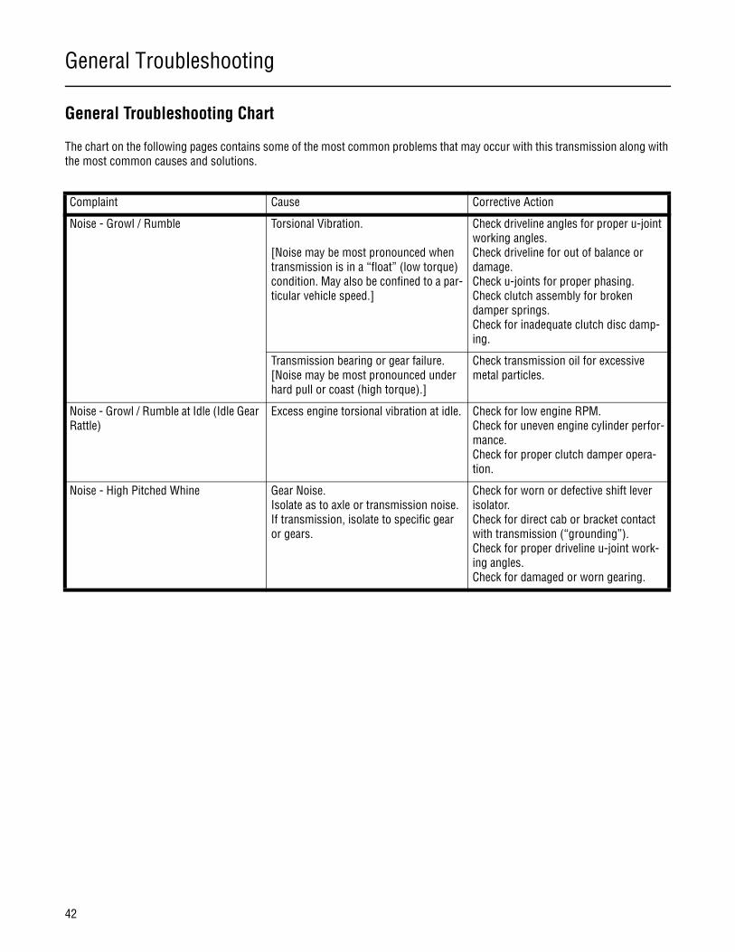
General Troubleshooting Chart
The chart on the following pages contains some of the most common problems that may occur with this transmission along with the most common causes and solutions.
Complaint Cause Corrective Action
Noise - Growl / Rumble Torsional Vibration. [Noise may be most pronounced when transmission is in a “float” (low torque) condition. May also be confined to a par-ticular vehicle speed.]
Check driveline angles for proper u-joint working angles.Check driveline for out of balance or damage.Check u-joints for proper phasing. Check clutch assembly for broken damper springs.Check for inadequate clutch disc damp-ing.
Transmission bearing or gear failure.[Noise may be most pronounced under hard pull or coast (high torque).]
Check transmission oil for excessive metal particles.
Noise - Growl / Rumble at Idle (Idle Gear Rattle)
Excess engine torsional vibration at idle. Check for low engine RPM.Check for uneven engine cylinder perfor-mance. Check for proper clutch damper opera-tion.
Noise - High Pitched Whine Gear Noise. Isolate as to axle or transmission noise. If transmission, isolate to specific gear or gears.
Check for worn or defective shift lever isolator.Check for direct cab or bracket contact with transmission (“grounding”).Check for proper driveline u-joint work-ing angles.Check for damaged or worn gearing.
General Troubleshooting
43
General Information
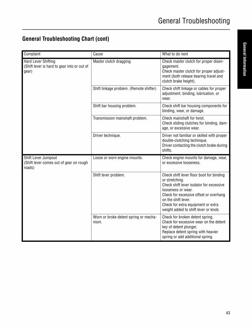
General Troubleshooting Chart (cont)
Complaint Cause What to do next
Hard Lever Shifting(Shift lever is hard to gear into or out of gear)
Master clutch dragging. Check master clutch for proper disen-gagement. Check master clutch for proper adjust-ment (both release bearing travel and clutch brake height).
Shift linkage problem. (Remote shifter) Check shift linkage or cables for proper adjustment, binding, lubrication, or wear.
Shift bar housing problem. Check shift bar housing components for binding, wear, or damage.
Transmission mainshaft problem. Check mainshaft for twist. Check sliding clutches for binding, dam-age, or excessive wear.
Driver technique. Driver not familiar or skilled with proper double-clutching technique.Driver contacting the clutch brake during shifts.
Shift Lever Jumpout(Shift lever comes out of gear on rough roads)
Loose or worn engine mounts. Check engine mounts for damage, wear, or excessive looseness.
Shift lever problem. Check shift lever floor boot for binding or stretching.Check shift lever isolator for excessive looseness or wear. Check for excessive offset or overhang on the shift lever.Check for extra equipment or extra weight added to shift lever or knob.
Worn or broke detent spring or mecha-nism.
Check for broken detent spring.Check for excessive wear on the detent key of detent plunger.Replace detent spring with heavier spring or add additional spring.

General Troubleshooting
44
General Troubleshooting Chart (cont)
Complaint Cause Corrective Action
Shift Lever Slipout(Transmission comes out of gear under torque)
Internal transmission problem. Check for excessively worn or damaged sliding clutches or shift yokes.
Transmission goes to neutral(Shift lever doesn’t move)
Low air pressure. Check air regulator pressure.
Internal transmission problem. Check for excessively worn or damaged range sliding clutch or yoke.
No range shift or slow range shift(Also see Air System Troubleshooting)
Transmission air system problem. Preform air system troubleshooting pro-cedure.Check for proper air signal from master valve.Check air module test ports for proper air delivery.
Range cylinder problem. Check for failed or damaged range pis-ton, piston bar, or cylinder.Check for failed or loose range piston snap ring.
Range yoke assembly problem. Check for failed or damaged range yoke.Check for failed or loose range yoke snap rings.Check for excessively long fastener installed in rear support hole.Check for binding between range yoke bar and range alignment lock cover.
Range synchronizer problem. Check for failed or damaged range syn-chronizer, sliding clutch, or mating gear.Check for excessively worn range syn-chronizer friction material.
Grinding Noise on Range Shift Driver not preselecting range shift. Instruct driver to preselect range shifts.
Range synchronizer worn or defective. Check range synchronizer and mating parts for excessive wear or damage.
Air System
45
General Information
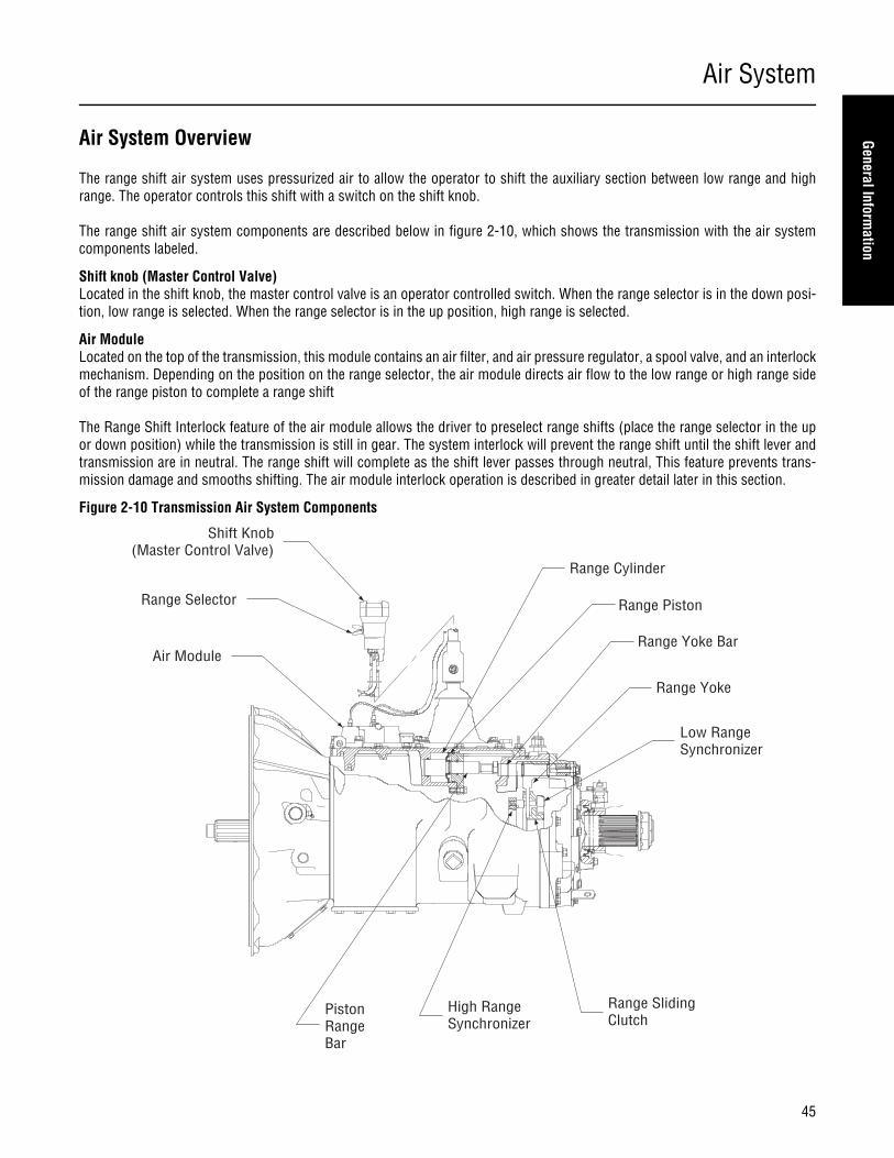
Air System Overview
The range shift air system uses pressurized air to allow the operator to shift the auxiliary section between low range and highrange. The operator controls this shift with a switch on the shift knob.
The range shift air system components are described below in figure 2-10, which shows the transmission with the air systemcomponents labeled.
Shift knob (Master Control Valve)Located in the shift knob, the master control valve is an operator controlled switch. When the range selector is in the down posi-tion, low range is selected. When the range selector is in the up position, high range is selected.
Air ModuleLocated on the top of the transmission, this module contains an air filter, and air pressure regulator, a spool valve, and an interlockmechanism. Depending on the position on the range selector, the air module directs air flow to the low range or high range sideof the range piston to complete a range shift
The Range Shift Interlock feature of the air module allows the driver to preselect range shifts (place the range selector in the upor down position) while the transmission is still in gear. The system interlock will prevent the range shift until the shift lever andtransmission are in neutral. The range shift will complete as the shift lever passes through neutral, This feature prevents trans-mission damage and smooths shifting. The air module interlock operation is described in greater detail later in this section.
Figure 2-10 Transmission Air System Components
Air Module
Shift Knob (Master Control Valve)
Range Cylinder
Range Piston
Range Yoke Bar
Range Yoke
Low RangeSynchronizer
Range SlidingClutch
High RangeSynchronizer
PistonRangeBar
Range Selector
Air System
46
Range Cylinder and PistonThe range cylinder is located on the underside of the shift bar housing. It contains the range piston and bar assembly. The rangepiston and bar assembly is connected with the range yoke bar to move the range sliding clutch back and forth. Depending on theposition of the range selector, pressurized air is supplied to the front or back of the range piston to shift the auxiliary section intolow or high range.
Range Bar and YokeLocated in the transmission auxiliary section, the range yoke bar and yoke move the range sliding clutch to low or high range. Therange yoke bar extends into the main case where it is connected with the range piston bar. The range yoke is positioned in the slotof the range sliding clutch. When the range cylinder moves the range bar and yoke, the yoke moves the sliding clutch into the highor low range position.
Range Sliding Clutch and SynchronizerThe range sliding clutch and synchronizer are located on the auxiliary mainshaft (output shaft). The range sliding clutch connectsthe auxiliary mainshaft to either the auxiliary drive gear (in high range) or the auxiliary reduction gear (in low range). The synchro-nizer allows the sliding clutch to move into gear without grinding.
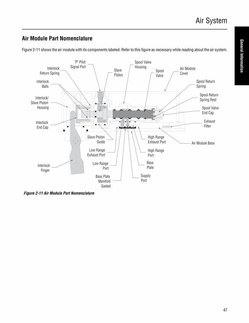
Air System
47
General Information
Air Module Part Nomenclature
Figure 2-11 shows the air module with its components labeled. Refer to this figure as necessary while reading about the air system.
Figure 2-11 Air Module Part Nomenclature
Low RangePort
SupplyPort
Base PlateManifold
Gasket
Base Plate
High RangePort
High RangeExhaust Port Air Module Base
ExhaustFilter
Spool ValveEnd Cap
Spool ReturnSpring Rest
Spool ReturnSpring
Air ModuleCover
SpoolValve
Spool ValveHousingInterlock
Return Spring
InterlockBalls
Interlock/Slave Piston
Housing
InterlockEnd Cap
Slave PistonGuide
InterlockFinger
SlavePiston
Low RangeExhaust Port
"P" PilotSignal Port
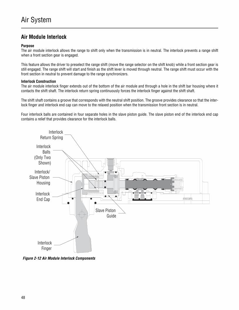
Air System
48
Air Module InterlockPurposeThe air module interlock allows the range to shift only when the transmission is in neutral. The interlock prevents a range shiftwhen a front section gear is engaged.
This feature allows the driver to preselect the range shift (move the range selector on the shift knob) while a front section gear isstill engaged. The range shift will start and finish as the shift lever is moved through neutral. The range shift must occur with thefront section in neutral to prevent damage to the range synchronizers.
Interlock ConstructionThe air module interlock finger extends out of the bottom of the air module and through a hole in the shift bar housing where itcontacts the shift shaft. The interlock return spring continuously forces the interlock finger against the shift shaft.
The shift shaft contains a groove that corresponds with the neutral shift position. The groove provides clearance so that the inter-lock finger and interlock end cap can move to the relaxed position when the transmission front section is in neutral.
Four interlock balls are contained in four separate holes in the slave piston guide. The slave piston end of the interlock end capcontains a relief that provides clearance for the interlock balls.
Figure 2-12 Air Module Interlock Components
InterlockReturn Spring
InterlockBalls
(Only TwoShown)
Interlock/Slave Piston
Housing
InterlockEnd Cap
Slave PistonGuide
InterlockFinger
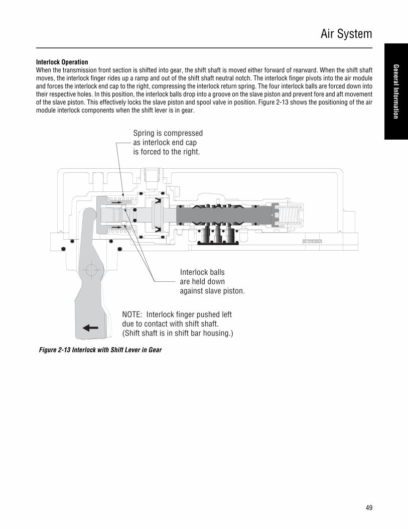
Air System
49
General Information
Interlock OperationWhen the transmission front section is shifted into gear, the shift shaft is moved either forward of rearward. When the shift shaftmoves, the interlock finger rides up a ramp and out of the shift shaft neutral notch. The interlock finger pivots into the air moduleand forces the interlock end cap to the right, compressing the interlock return spring. The four interlock balls are forced down intotheir respective holes. In this position, the interlock balls drop into a groove on the slave piston and prevent fore and aft movementof the slave piston. This effectively locks the slave piston and spool valve in position. Figure 2-13 shows the positioning of the airmodule interlock components when the shift lever is in gear.
Figure 2-13 Interlock with Shift Lever in Gear
Interlock balls are held down against slave piston.
Spring is compressed as interlock end cap is forced to the right.
NOTE: Interlock finger pushed left due to contact with shift shaft.(Shift shaft is in shift bar housing.)

Air System
50
When the transmission is shifted to neutral, the interlock return spring forces the interlock end cap to the left as the interlock fingerpivots into the neutral notch on the shift shaft. The interlock balls can now move up out of the groove on the slave piston and theslave piston can move freely. Figure 2-14 shows the positioning of the air module interlock components when the shift lever is inneutral.
Figure 2-14 Interlock with Shift Lever in Neutral
Interlock balls can move away from slave piston.
Spring forcesinterlock end capand finger to the left.
NOTE: Interlock finger in relaxed position against shift shaft notch.
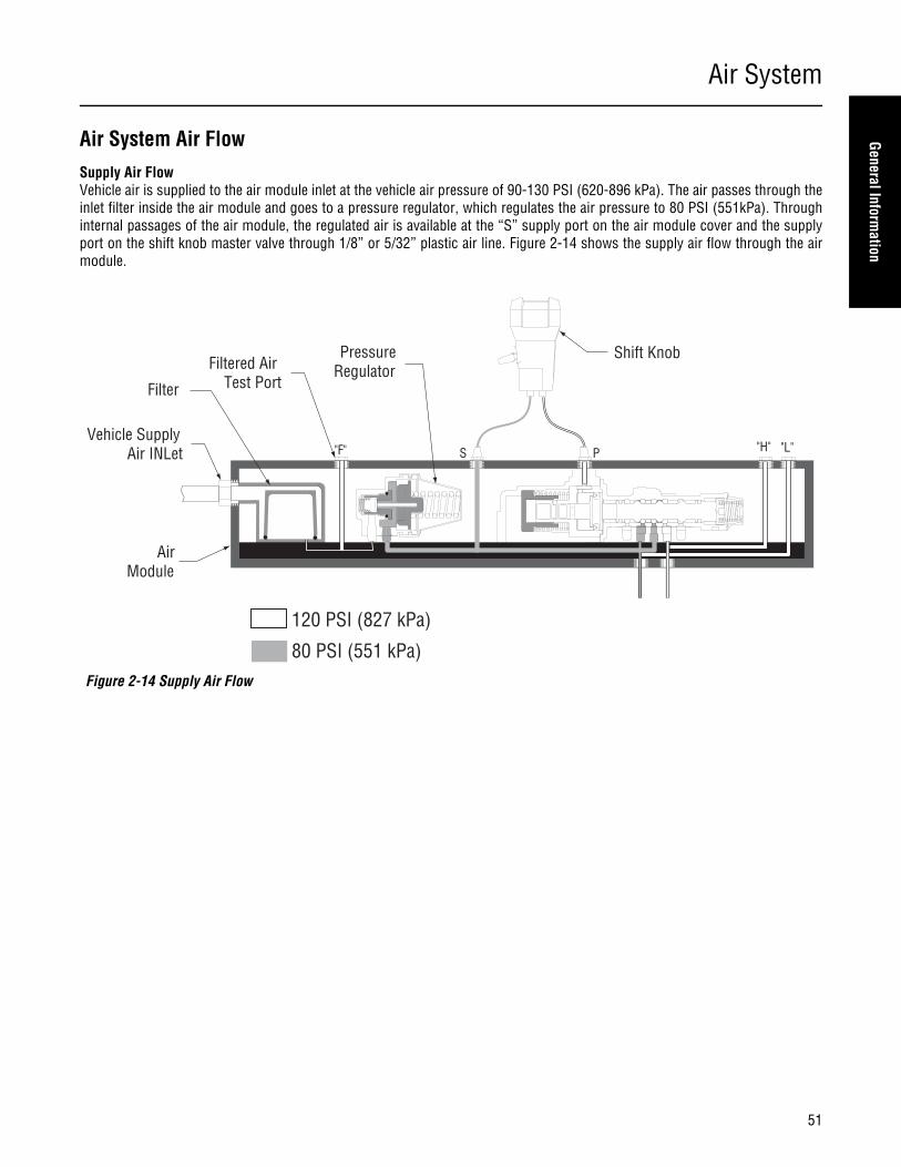
Air System
51
General Information
Air System Air FlowSupply Air FlowVehicle air is supplied to the air module inlet at the vehicle air pressure of 90-130 PSI (620-896 kPa). The air passes through theinlet filter inside the air module and goes to a pressure regulator, which regulates the air pressure to 80 PSI (551kPa). Throughinternal passages of the air module, the regulated air is available at the “S” supply port on the air module cover and the supplyport on the shift knob master valve through 1/8” or 5/32” plastic air line. Figure 2-14 shows the supply air flow through the airmodule.
Figure 2-14 Supply Air Flow
Shift Knob
AirModule
Vehicle Supply Air INLet
Filtered AirTest Port
"H" "L"
Filter
PressureRegulator
120 PSI (827 kPa)
80 PSI (551 kPa)
"F" S P
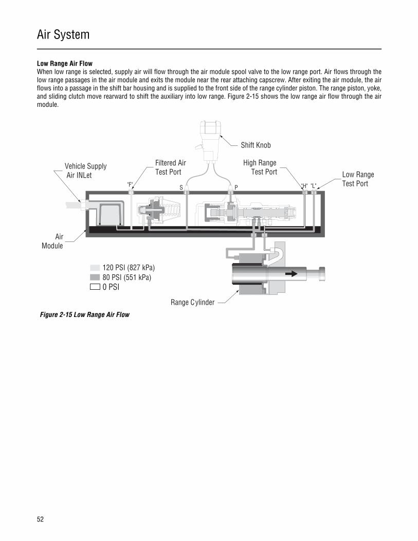
Air System
52
Low Range Air FlowWhen low range is selected, supply air will flow through the air module spool valve to the low range port. Air flows through thelow range passages in the air module and exits the module near the rear attaching capscrew. After exiting the air module, the airflows into a passage in the shift bar housing and is supplied to the front side of the range cylinder piston. The range piston, yoke,and sliding clutch move rearward to shift the auxiliary into low range. Figure 2-15 shows the low range air flow through the airmodule.
Figure 2-15 Low Range Air Flow
Shift Knob
AirModule
Vehicle Supply Air INLet
Filtered AirTest Port
Range Cylinder
High RangeTest Port Low Range
Test PortS P "H" "L""F"
120 PSI (827 kPa)80 PSI (551 kPa)0 PSI
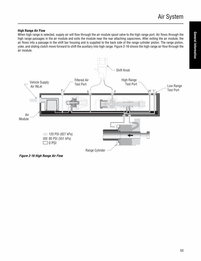
Air System
53
General Information
High Range Air FlowWhen high range is selected, supply air will flow through the air module spool valve to the high range port. Air flows through thehigh range passages in the air module and exits the module near the rear attaching capscrews. After exiting the air module, theair flows into a passage in the shift bar housing and is supplied to the back side of the range cylinder piston. The range piston,yoke, and sliding clutch move forward to shift the auxiliary into high range. Figure 2-16 shows the high range air flow through theair module.
Figure 2-16 High Range Air Flow
Shift Knob
AirModule
Range Cylinder
High RangeTest Port Low Range
Test PortS P"F"
120 PSI (827 kPa)80 PSI (551 kPa)0 PSI
Vehicle Supply Air INLet
Filtered AirTest Port
"H" "L"

Air System
54
Air Module OperationLow Range - Shift Lever in NeutralWhen the range lever on the shift knob is placed in the down (low range) position, air flows through the master control valve andback to the air module through 5/32” air line. This signal air will enter the air module at the “P” port where it will enter the slavepiston chamber. With the shift lever in neutral, the air pressure will move the slave piston and spool valve to the full right positionas shown in figure 2-17, and the spool return spring will be compressed. At this point, the supply port will be connected with thelow range port, and the high range port will be exhausted. Pressurized air will move the range piston, bars, range yoke, and rangesliding clutch to the low range position.
Low Range - Shift Lever in GearWhen the transmission is shifted into gear, the interlock mechanism will shift to the right as shown in Figure 2-18, locking theslave piston and spool valve into position. Air flow through the air module is not affected.
Figure 2-17 Air Flow for Low Range with Shift Lever in Neutral
Figure 2-18 Air Flow for Low Range with Shift Lever in Gear
Low Range
Supply
High Range
ExhaustExhaust
"P" Pilot Signal
Low Range
Supply
High Range
ExhaustExhaust
"P" Pilot Signal
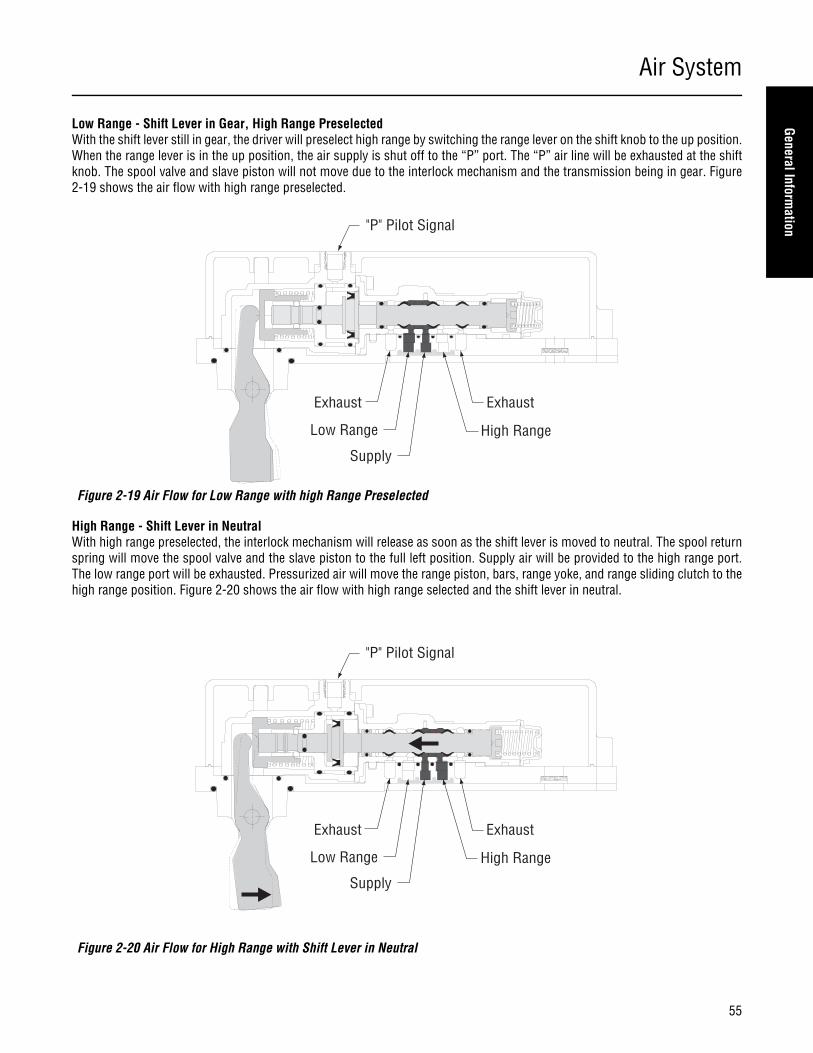
Air System
55
General Information
Low Range - Shift Lever in Gear, High Range PreselectedWith the shift lever still in gear, the driver will preselect high range by switching the range lever on the shift knob to the up position.When the range lever is in the up position, the air supply is shut off to the “P” port. The “P” air line will be exhausted at the shiftknob. The spool valve and slave piston will not move due to the interlock mechanism and the transmission being in gear. Figure2-19 shows the air flow with high range preselected.
High Range - Shift Lever in NeutralWith high range preselected, the interlock mechanism will release as soon as the shift lever is moved to neutral. The spool returnspring will move the spool valve and the slave piston to the full left position. Supply air will be provided to the high range port.The low range port will be exhausted. Pressurized air will move the range piston, bars, range yoke, and range sliding clutch to thehigh range position. Figure 2-20 shows the air flow with high range selected and the shift lever in neutral.
Figure 2-19 Air Flow for Low Range with high Range Preselected
Figure 2-20 Air Flow for High Range with Shift Lever in Neutral
Low Range
Supply
High Range
ExhaustExhaust
"P" Pilot Signal
Low Range
Supply
High Range
ExhaustExhaust
"P" Pilot Signal

Air System
56
High Range - Shift Lever in GearWhen the shift lever is moved into gear, the interlock finger moves the interlock end cap to the right, which activates the interlockmechanism. It also moves the slave piston and spool valve partially to the right. The partial travel of the spool valve exposes thelow range port to pressurized air from the supply port. Supply air is available to both the low and high range ports, and both ex-haust ports are sealed. Equal air pressure is available on both sides of the range cylinder piston. Because the high range side ofthe piston has more available surface area than the low range side, the range remains in high range. Figure 2-21 shows the airflow with high range selected and the shift lever in gear.
Figure 2-21 Air Flow for High Range with Shift Lever in Gear
Low Range
Supply
High Range
ExhaustExhaust
"P" Pilot Signal
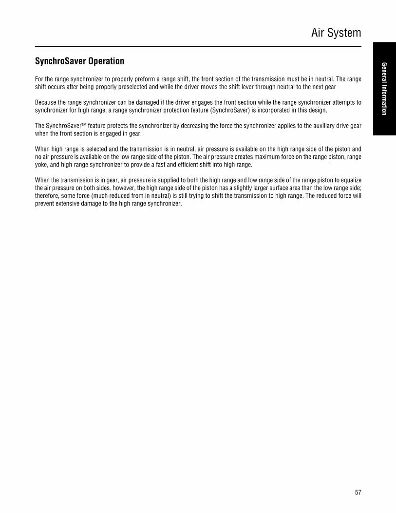
Air System
57
General Information
SynchroSaver Operation
For the range synchronizer to properly preform a range shift, the front section of the transmission must be in neutral. The rangeshift occurs after being properly preselected and while the driver moves the shift lever through neutral to the next gear
Because the range synchronizer can be damaged if the driver engages the front section while the range synchronizer attempts tosynchronizer for high range, a range synchronizer protection feature (SynchroSaver) is incorporated in this design.
The SynchroSaver™ feature protects the synchronizer by decreasing the force the synchronizer applies to the auxiliary drive gearwhen the front section is engaged in gear.
When high range is selected and the transmission is in neutral, air pressure is available on the high range side of the piston andno air pressure is available on the low range side of the piston. The air pressure creates maximum force on the range piston, rangeyoke, and high range synchronizer to provide a fast and efficient shift into high range.
When the transmission is in gear, air pressure is supplied to both the high range and low range side of the range piston to equalizethe air pressure on both sides. however, the high range side of the piston has a slightly larger surface area than the low range side;therefore, some force (much reduced from in neutral) is still trying to shift the transmission to high range. The reduced force willprevent extensive damage to the high range synchronizer.

Air System
58
Air System Nomenclature
Figures 4-1 through 4-3 below show the air module, shift knob, and range alignment lock cover (earlier models) with their com-ponents labeled. These are the primary components used during troubleshooting. If necessary, refer to these figures while trou-bleshooting the air system.
Figure 4-1 Air Module Ports
Figure 4-2 Shift Knob Components Figure 4-3 Range Alignment Lock Cover
41 P
21 S
22 F
1 IN 23 H25 L
Pilot Signal Port
Supply Port
Vehicle SupplyAir INlet
High RangeTest Port (1/16" NPT)
Low RangeTest Port (1/16" NPT)
Filtered VehicleSupply Air Test Port (1/16" NPT)
ShiftKnob
RangeSelector
Auxiliary SectionHousing
Indication Notch
RangeAlignmentLock Cover
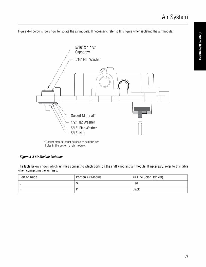
Air System
59
General Information
Figure 4-4 below shows how to isolate the air module. If necessary, refer to this figure when isolating the air module.
The table below shows which air lines connect to which ports on the shift knob and air module. If necessary, refer to this tablewhen connecting the air lines.
Figure 4-4 Air Module Isolation
Port on Knob Port on Air Module Air Line Color (Typical)
S S Red
P P Black
Gasket Material*
1/2" Flat Washer5/16" Flat Washer
5/16" Flat Washer
5/16" X 1 1/2"Capscrew
5/16" Nut
* Gasket material must be used to seal the two holes in the bottom of air module.

Timing
60
Timing Procedures
Special Instructions
It is essential that both countershaft assemblies of the front and auxiliary sections are "timed." This assures proper tooth contactis made between mainshaft gears seeking to center on the mainshaft during torque transfer and mating countershaft gears thatdistribute the load evenly. If not properly timed, serious damage to the transmission is likely to result from unequal tooth contactcausing the mainshaft gears to climb out of equilibrium.
Timing is a simple procedure of marking the appropriate teeth of a gear set prior to installation and placing them in proper meshwhile in the transmission. In the front section, it is necessary to time only the drive gear set. And depending on the model, onlythe LO range, deep reduction, or splitter gear set is timed in the auxiliary section.
Procedure - Front Section
1. Marking countershaft drive gear teeth: Prior to placingeach countershaft assembly into the case, clearly mark thetooth located directly over the drive gear keyway as shown.This tooth is stamped with an "O" to aid identification.
2. Marking main drive gear teeth: Mark any two adjacent teethon the main drive gear.
Mark the two adjacent teeth located directly opposite thefirst set marked on the main drive gear. As shown to the left,there should be an equal number of unmarked gear teeth oneach side between the marked sets.
3. Meshing marked countershaft drive gear teeth withmarked main drive gear teeth: After placing the mainshaftassembly into the case, the countershaft bearings are in-stalled to complete installation of the countershaft assem-blies.
When installing the bearings on the left countershaft, meshthe countershaft drive gear marked tooth with either set ofmain drive gear two marked teeth.
Repeat the procedure when installing the bearings on theright countershaft, make use of the remaining set of maindrive gear two marked teeth to time assembly.
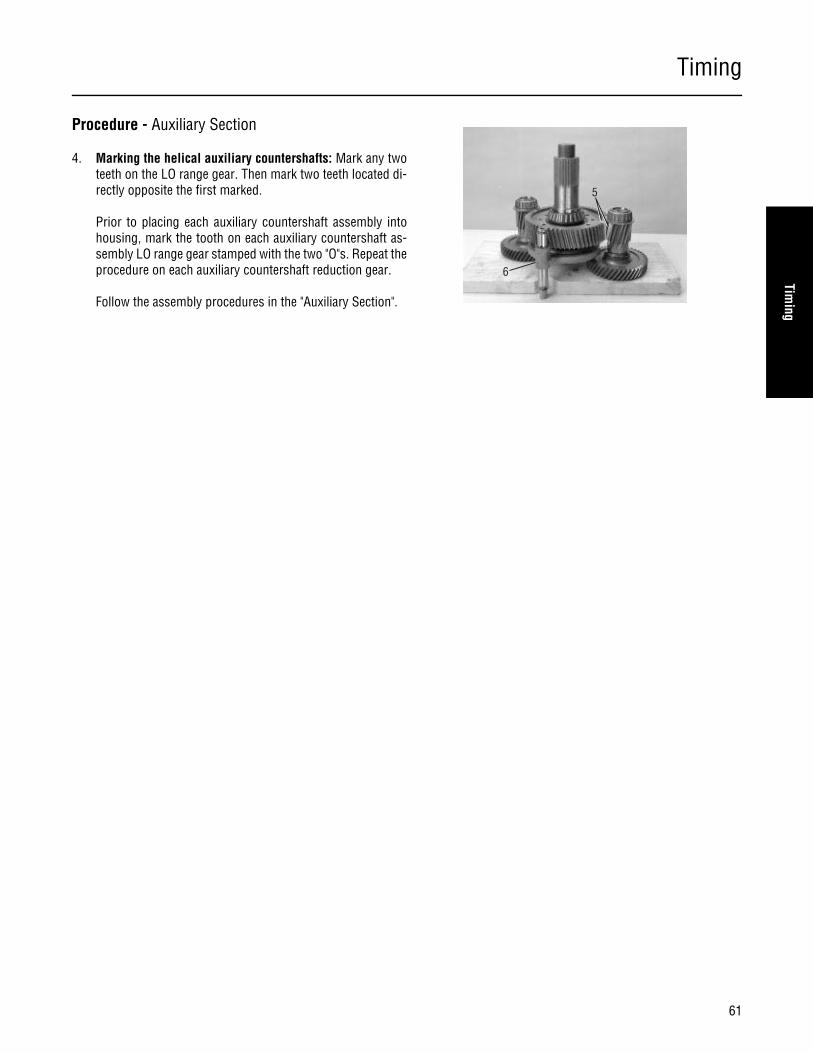
Timing
61
Timing
Procedure - Auxiliary Section
4. Marking the helical auxiliary countershafts: Mark any twoteeth on the LO range gear. Then mark two teeth located di-rectly opposite the first marked.
Prior to placing each auxiliary countershaft assembly intohousing, mark the tooth on each auxiliary countershaft as-sembly LO range gear stamped with the two "O"s. Repeat theprocedure on each auxiliary countershaft reduction gear.
Follow the assembly procedures in the "Auxiliary Section".
6
5

In-Vehicle Service Procedures
62
How to Disassemble the Roadranger Valve
Special Instructions
None
Special Tools
• Typical service tools
Component Nomenclature and Auxiliary Countershaft Sectional View
1. Medallion2. Spring3. Lever4. Cover5. Screw6. Ball 5/32”
7. Retainer8. O-Ring9. Old Style Shift Knob
1
2 2 6
2 2 8
8 3
4
5
5
Old Design
5
5
6
79

In-Vehicle Service Procedures
63
In-Vehicle Service Procedures
Procedure -
1. Remove the two screws holding the bottom cover to thevalve and slide the cover down the gearshift lever to exposeair line fittings. Disconnect the air lines.
2. Loosen the jam nut and turn the Roadranger valve from thegear shift lever.
3. Pry the medallion from the recess in the top cover.
4. Turn out the two screws to remove the top cover from thevalve housing.
5. Turn out the two screws in the side of the valve housing toseparate the housing.
6. Remove the range selection lever from the left housing alongwith the position balls and guide.
7. If necessary, remove the spring and O-ring from the boresin the left housing.
8. If necessary, remove the springs, O-ring and sleeve from thebores in the right housing.

In-Vehicle Service Procedures
64
How to Assemble the Roadranger Valve
Special Instructions
None
Special Tools
• Typical service tools
Component Nomenclature and Auxiliary Countershaft Sectional View
1. Medallion2. Spring3. Lever4. Cover5. Screw6. Ball 5/32”
7. Retainer8. O-Ring9. Old Style Shift Knob
1
2 2 6
2 2 8
8 3
4
5
5
Old Design
5
5
6
79
In-Vehicle Service Procedures
65
In-Vehicle Service Procedures
Procedure -
1. Refer to the drawing for proper reassembly. Use a very smallamount of silicone lubricant on the O-rings to avoid cloggingthe ports. A small amount of grease on the position springsand balls will help to hold them in place during reassembly.
2. Reinstall Roadranger valve on gear shift lever and tighten thejam nut.
3. Attach the air lines and reinstall the bottom cover.
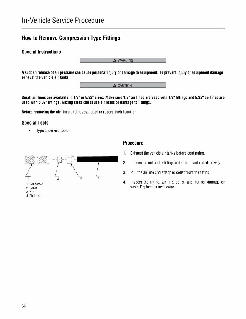
In-Vehicle Service Procedure
66
How to Remove Compression Type Fittings
Special Instructions
A sudden release of air pressure can cause personal injury or damage to equipment. To prevent injury or equipment damage,exhaust the vehicle air tanks
Small air lines are available in 1/8" or 5/32" sizes. Make sure 1/8" air lines are used with 1/8" fittings and 5/32" air lines areused with 5/32" fittings. Mixing sizes can cause air leaks or damage to fittings.
Before removing the air lines and hoses, label or record their location.
Special Tools
• Typical service tools
Procedure -
1. Exhaust the vehicle air tanks before continuing.
2. Loosen the nut on the fitting, and slide it back out of the way.
3. Pull the air line and attached collet from the fitting.
4. Inspect the fitting, air line, collet, and nut for damage orwear. Replace as necessary.
WARNING
CAUTION

In-Vehicle Service Procedure
67
In-Vehicle Service Procedure
How to Install Compression Type Fittings
Special Instructions
A sudden release of air pressure can cause personal injury or damage to equipment. To prevent injury or equipment damage,exhaust the vehicle air tanks
Small air lines are available in 1/8" or 5/32" sizes. Make sure 1/8" air lines are used with 1/8" fittings and 5/32" air lines areused with 5/32" fittings. Mixing sizes can cause air leaks or damage to fittings.
Special Tools
• Typical service tools
Procedure -
1. Check the threads of the fitting for thread sealant. If no seal-ant is present, apply Eaton® Fuller® thread sealant #71205or equivalent.
2. Install the fitting.
Note: Do not overtighten the nut. Overtightening can com-press the collet too much and cause an air line restric-tion.
3. Install the air line, collet, and nut. If installing a new fitting,place the collet in the fitting and loosely install the nut. (Donot tighten the nut yet.) Insert the air line through the nutand into the collet. Tighten the nut as usual.
4. Enable the vehicle air system. Allow the air tanks to pressur-ize, and check for leaks. Repair as necessary.
WARNING
CAUTION
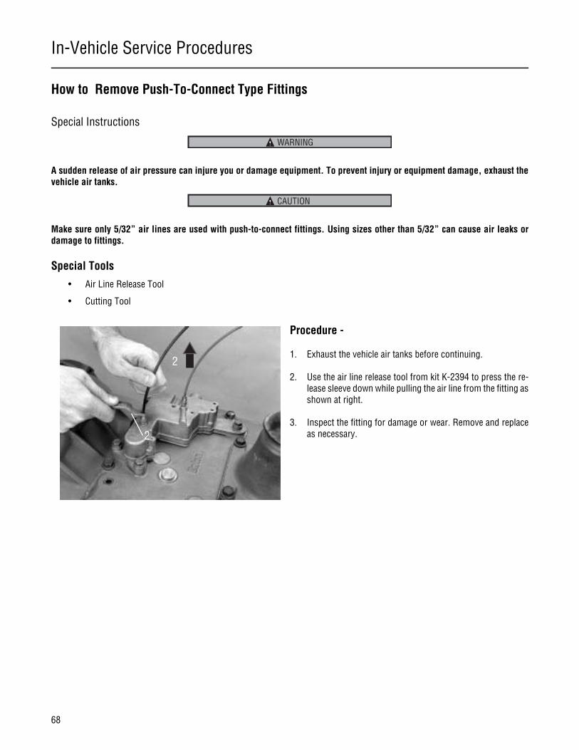
In-Vehicle Service Procedures
68
How to Remove Push-To-Connect Type Fittings
Special Instructions
A sudden release of air pressure can injure you or damage equipment. To prevent injury or equipment damage, exhaust thevehicle air tanks.
Make sure only 5/32” air lines are used with push-to-connect fittings. Using sizes other than 5/32” can cause air leaks ordamage to fittings.
Special Tools
• Air Line Release Tool
• Cutting Tool
Procedure -
1. Exhaust the vehicle air tanks before continuing.
2. Use the air line release tool from kit K-2394 to press the re-lease sleeve down while pulling the air line from the fitting asshown at right.
3. Inspect the fitting for damage or wear. Remove and replaceas necessary.
WARNING
CAUTION
2
2

In-Vehicle Service Procedures
69
In-Vehicle Service Procedures
How to Install Push-To-Connect Type Fittings
Special Instructions
None
Special Tools
• Air Line Cutting Tool
Procedure -
1. Check the threads of the fitting for thread sealant. If no seal-ant is present, apply Eaton®Fuller® thread sealant #71205or equivalent.
2. Install the fitting.
3. Inspect the air line for burrs or deformed areas. Trim the airline if necessary using a sharp razor blade or the air line cut-ting tool from kit K-2394. The cut must be smooth andsquare. If the tubing end is deformed or burred, the internalO-ring in the fitting will be damaged when the air line is in-serted.
4. Push the air line into the fitting. It should insert approximate-ly 3/4”. If it does not insert far enough or is difficult to insert,the fitting may be damaged and should be replaced. After in-serting, give the air line a slight tug to make sure the linestays in place. If line does not stay in place, replace the fit-ting.
5. Enable the vehicle air system. Allow the air tanks to pressur-ize, and check for leaks.
3
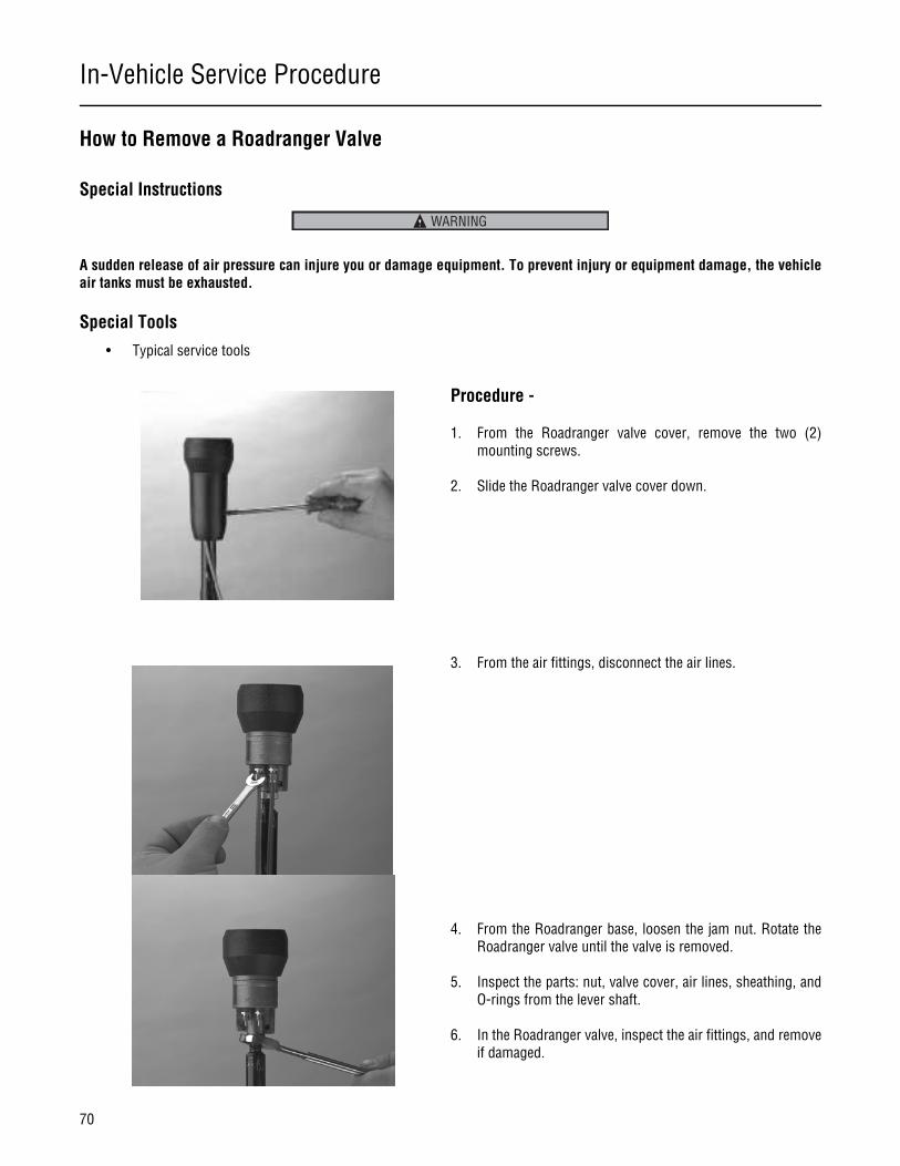
In-Vehicle Service Procedure
70
How to Remove a Roadranger Valve
Special Instructions
A sudden release of air pressure can injure you or damage equipment. To prevent injury or equipment damage, the vehicleair tanks must be exhausted.
Special Tools
• Typical service tools
Procedure -
1. From the Roadranger valve cover, remove the two (2)mounting screws.
2. Slide the Roadranger valve cover down.
3. From the air fittings, disconnect the air lines.
4. From the Roadranger base, loosen the jam nut. Rotate theRoadranger valve until the valve is removed.
5. Inspect the parts: nut, valve cover, air lines, sheathing, andO-rings from the lever shaft.
6. In the Roadranger valve, inspect the air fittings, and removeif damaged.
WARNING
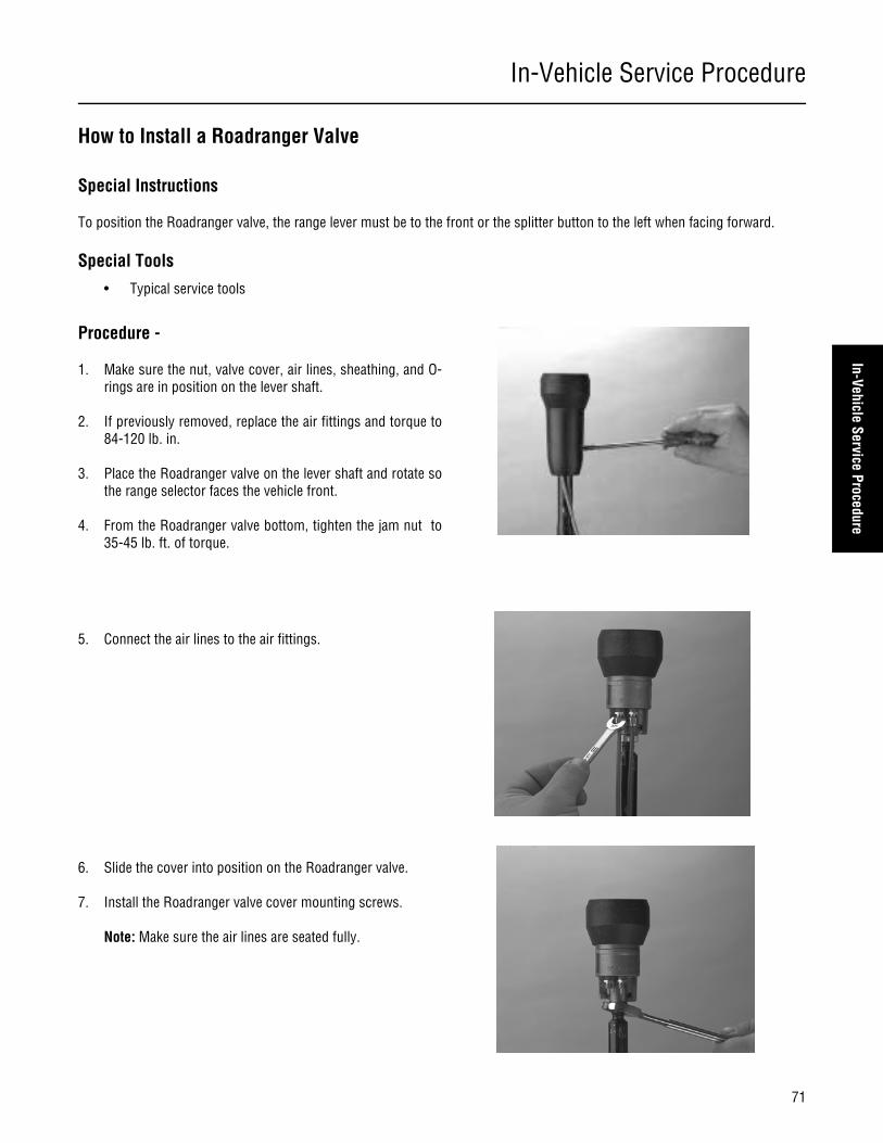
In-Vehicle Service Procedure
71
In-Vehicle Service Procedure
How to Install a Roadranger Valve
Special Instructions
To position the Roadranger valve, the range lever must be to the front or the splitter button to the left when facing forward.
Special Tools
• Typical service tools
Procedure -
1. Make sure the nut, valve cover, air lines, sheathing, and O-rings are in position on the lever shaft.
2. If previously removed, replace the air fittings and torque to84-120 lb. in.
3. Place the Roadranger valve on the lever shaft and rotate sothe range selector faces the vehicle front.
4. From the Roadranger valve bottom, tighten the jam nut to35-45 lb. ft. of torque.
5. Connect the air lines to the air fittings.
6. Slide the cover into position on the Roadranger valve.
7. Install the Roadranger valve cover mounting screws.
Note: Make sure the air lines are seated fully.

In-Vehicle Service Procedure
72
How to Remove the Gear Shift Lever/Remote Shift Control
Special Instructions
The air lines must be disconnected from the transmission or from the Roadranger valve.
Different detent springs are available to increase or decrease shifting effort. Note and record specific locations for specific springs.In some cases, a stiffer spring is installed in the top rail position.
Remote control housings are removed the same way as gear shift levers.
Special Tools
• Typical service tools
Procedure -
1. From the gear shift lever base/shift control housing, removethe four (4) retaining capscrews.
2. To break the gasket seal, lightly jar the gear shift/shift con-trol housing.
3. Remove the gear shift lever housing.
Make sure the detent springs do not fall into the transmis-sion.
4. Remove detent springs as needed.
5. Remove the gasket and clean the area the replacement gas-ket will contact.
CAUTION

In-Vehicle Service Procedure
73
In-Vehicle Service Procedure
How to Install the Gear Shift Lever/Remote Shift Control
Special Instructions
Remote control housings are installed the same way as gear shift levers.
For standard and forward shift bar housings, make sure the detent springs and balls are in the shift bar housing top bores.
Make sure the shift block and yoke notches are aligned in the neutral position.
Special Tools
• Typical service tools
Procedure -
1. Thoroughly clean mounting surface.
2. Position a new gear shift lever/shift control housing gasketon the gear shift lever mounting surface.
3. Install the detent springs.
4. Install the shift lever/shift control housing. Make sure the tip(finger) of the gear shift lever fits into the slots in the shiftblock.
5. Apply Eaton/Fuller Sealant #71205 or equivalent to the re-taining capscrews.
6. Install the retaining capscrews, tighten to 35-45 lbs.ft. oftorque.
Note: Make sure the capscrews are properly torqued.
Note: Make sure you can shift the transmission.
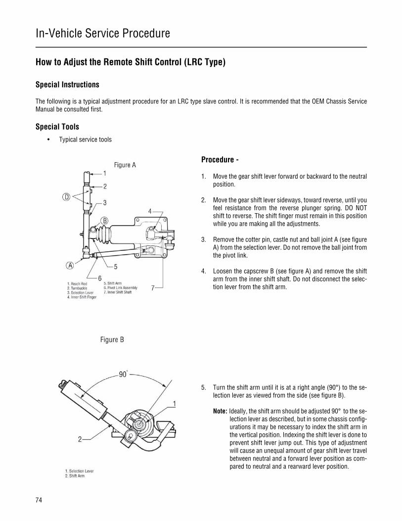
In-Vehicle Service Procedure
74
How to Adjust the Remote Shift Control (LRC Type)
Special Instructions
The following is a typical adjustment procedure for an LRC type slave control. It is recommended that the OEM Chassis ServiceManual be consulted first.
Special Tools
• Typical service tools
Procedure -
1. Move the gear shift lever forward or backward to the neutralposition.
2. Move the gear shift lever sideways, toward reverse, until youfeel resistance from the reverse plunger spring. DO NOTshift to reverse. The shift finger must remain in this positionwhile you are making all the adjustments.
3. Remove the cotter pin, castle nut and ball joint A (see figureA) from the selection lever. Do not remove the ball joint fromthe pivot link.
4. Loosen the capscrew B (see figure A) and remove the shiftarm from the inner shift shaft. Do not disconnect the selec-tion lever from the shift arm.
5. Turn the shift arm until it is at a right angle (90°) to the se-lection lever as viewed from the side (see figure B).
Note: Ideally, the shift arm should be adjusted 90° to the se-lection lever as described, but in some chassis config-urations it may be necessary to index the shift arm inthe vertical position. Indexing the shift lever is done toprevent shift lever jump out. This type of adjustmentwill cause an unequal amount of gear shift lever travelbetween neutral and a forward lever position as com-pared to neutral and a rearward lever position.
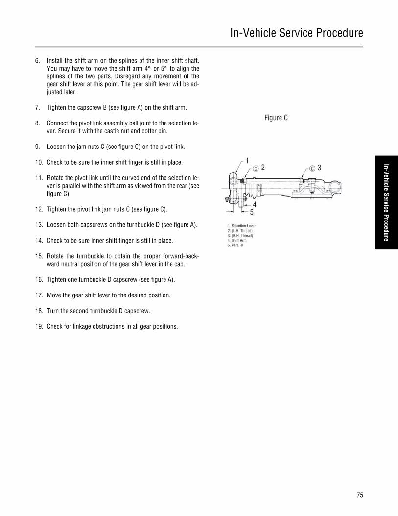
In-Vehicle Service Procedure
75
In-Vehicle Service Procedure
6. Install the shift arm on the splines of the inner shift shaft.You may have to move the shift arm 4° or 5° to align thesplines of the two parts. Disregard any movement of thegear shift lever at this point. The gear shift lever will be ad-justed later.
7. Tighten the capscrew B (see figure A) on the shift arm.
8. Connect the pivot link assembly ball joint to the selection le-ver. Secure it with the castle nut and cotter pin.
9. Loosen the jam nuts C (see figure C) on the pivot link.
10. Check to be sure the inner shift finger is still in place.
11. Rotate the pivot link until the curved end of the selection le-ver is parallel with the shift arm as viewed from the rear (seefigure C).
12. Tighten the pivot link jam nuts C (see figure C).
13. Loosen both capscrews on the turnbuckle D (see figure A).
14. Check to be sure inner shift finger is still in place.
15. Rotate the turnbuckle to obtain the proper forward-back-ward neutral position of the gear shift lever in the cab.
16. Tighten one turnbuckle D capscrew (see figure A).
17. Move the gear shift lever to the desired position.
18. Turn the second turnbuckle D capscrew.
19. Check for linkage obstructions in all gear positions.

In-Vehicle Service Procedures
76
How to Remove the Detent Spring
Special Instructions
None
Special Tools
• Typical service tools
Procedure -
1. Remove the shift lever or remote shift control according tothe “Shift Lever/Remote Shift Control Removal” instructionsin this section.
2. Remove the shift block socket head capscrew using an 8mm or 5/16” hex driver.
3. Gently pry the shift block loose, and lift it straight up to pre-vent the detent plunger and spring from falling into thetransmission case.
4. Remove the detent plunger and spring(s).
Note: Some transmissions may have two springs to in-crease the detent force.
Detent Plunger
Detent Spring
Capscrew
Shift Block
Optional SpringDesign
2
3
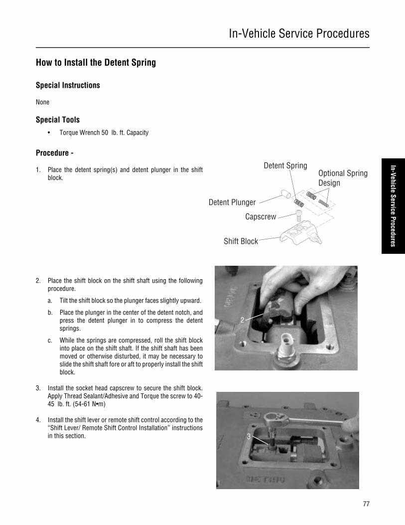
In-Vehicle Service Procedures
77
In-Vehicle Service Procedures
How to Install the Detent Spring
Special Instructions
None
Special Tools
• Torque Wrench 50 lb. ft. Capacity
Procedure -
1. Place the detent spring(s) and detent plunger in the shiftblock.
2. Place the shift block on the shift shaft using the followingprocedure.
a. Tilt the shift block so the plunger faces slightly upward.
b. Place the plunger in the center of the detent notch, andpress the detent plunger in to compress the detentsprings.
c. While the springs are compressed, roll the shift blockinto place on the shift shaft. If the shift shaft has beenmoved or otherwise disturbed, it may be necessary toslide the shift shaft fore or aft to properly install the shiftblock.
3. Install the socket head capscrew to secure the shift block.Apply Thread Sealant/Adhesive and Torque the screw to 40-45 lb. ft. (54-61 N•m)
4. Install the shift lever or remote shift control according to the“Shift Lever/ Remote Shift Control Installation” instructionsin this section.
Detent Plunger
Detent Spring
Capscrew
Shift Block
Optional SpringDesign
2
3

In-Vehicle Service Procedures
78
Neutral Switch Operation and Testing
Special Instructions
The neutral switch is a normally closed switch. An electrical current flows through it when the transmission shifter is in the centerneutral position. When the transmission shifter is in gear or a side neutral position, the switch is open and no current flows throughit.
Special Tools
• Ohm Meter
Procedure -
1. Disconnect the wiring from the switch by lifting the connec-tor locking tab and pulling the connector out of the switch.
2. Connect an ohm meter to check for continuity or a smallreading.
3. Place the transmission shift lever in the center neutral posi-tion. The ohm meter should register continuity or a smallreading. If it does, go to the next step. If it does not, removethe switch and replace it according to the removal instruc-tions below.
4. Shift the transmission into all gear positions. The ohm metershould read open or infinity. If it does not, remove theswitch, recheck it for continuity, and replace it as necessary.Also, check for the presence of the neutral switch pin.
Center Neutral Position(Neutral Switch Active)
Shift PositionDiagram
R 27
49
16
38
510

In-Vehicle Service Procedures
79
In-Vehicle Service Procedures
How to Remove the Neutral Switch
Special Instructions
If the ohm meter responds as indicated in the test procedure, do not perform this procedure as the switch is in good workingcondition.
Special Tools
• Typical service tools
Procedure -
1. Remove the switch using a 22 mm or 7/8” deep well socketor box end wrench.
2. Check for the presence of the neutral pin in the bore underthe switch.
3. While watching the neutral pin, move the transmission inand out of gear. The pin should raise up when the transmis-sion is in gear and lower when the transmission is in neutral.If the pin does not operate properly, remove the pin with amagnet and check it for wear. Also, remove the shift barhousing and check the shift shaft for wear.
4. Remove the pin from the bore with a magnet and check it forexcessive wear. If it is worn, replace it.
5. If the pin is present and not worn, replace the switch with anew one.
Reverse Switch
Reverse PinO-ring
Neutral Switch
O-ring
Neutral Pin
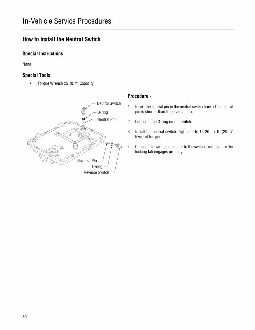
In-Vehicle Service Procedures
80
How to Install the Neutral Switch
Special Instructions
None
Special Tools
• Torque Wrench 25 lb. ft. Capacity
Procedure -
1. Insert the neutral pin in the neutral switch bore. (The neutralpin is shorter than the reverse pin).
2. Lubricate the O-ring on the switch.
3. Install the neutral switch. Tighten it to 15-20 lb. ft. (20-27N•m) of torque.
4. Connect the wiring connector to the switch, making sure thelocking tab engages properly.
Reverse Switch
Reverse PinO-ring
Neutral Switch
O-ring
Neutral Pin
In-Vehicle Service Procedures
81
In-Vehicle Service Procedures
Reverse Switch Operation and Testing
Special Instructions
The reverse switch is a normally open ball switch. When the transmission is shifted into reverse, a ramp on the reverse shift yokecontacts and raises a pin. The pin depresses the ball on the switch, which closes the switch contact, allowing current to flowthrough the switch and light up the vehicle’s backup lights.
Special Tools
• Ohm Meter
Procedure -
1. Disconnect the wiring from the switch by lifting the connec-tor locking tab and pulling the connector out of the switch.
2. Connect an ohm meter to test for continuity.
3. Place the transmission shift lever in any position except re-verse. If the switch is working properly, the ohm metershould read open or infinity. If it is not, remove the switchand recheck it for continuity. Replace it as necessary.
4. Place the transmission shift lever in the reverse position. Ifthe switch is working properly, the ohm meter should regis-ter continuity, or a small reading. If it does not, remove theswitch and recheck it for continuity. Replace it as necessary.Also, check for the presence of the reverse pin.
Reverse Switch
Reverse PinO-ring
Neutral Switch
O-ring
Neutral Pin
In-Vehicle Service Procedures
82
How to Remove the Reverse Switch
Special Instructions
If the ohm meter responds as indicated in the test procedure, do not perform this procedure as the switch is in good workingcondition.
Special Tools
• Typical service tools
Procedure -
1. Remove the switch using a 22 mm or 7/8” deep well socketor box end wrench.
2. Check for the presence of the reverse pin in the bore underthe switch.
3. While watching the reverse pin, move the transmissionshifter between the reverse position and any gear. The pinshould raise when the transmission is shifted to reverse andlower when the transmission is in neutral. If the pin does notraise and lower, inspect it to see if something is causing it tostick, and inspect it for wear. Also, remove the shift towerand check for wear on the reverse yoke ramp. This ramp canbe seen through the shifter opening.
4. Remove the pin from the bore with a magnet and check it forexcessive wear. If it is worn, replace it.
5. If the pin is present and not worn, replace the switch with anew one.
Reverse Switch
Reverse PinO-ring
Neutral Switch
O-ring
Neutral Pin
In-Vehicle Service Procedures
83
In-Vehicle Service Procedures
How to Install the Reverse Switch
Special Instructions
None
Special Tools
• Torque Wrench 25 lb. ft. Capacity
Procedure -
1. Insert the reverse pin in the reverse switch bore. (The re-verse pin is longer than the neutral pin.)
2. Lubricate the O-ring on the switch.
3. Install the reverse switch. Tighten it to 15-20 lb. ft. (20-27N•m) of torque.
4. Connect the wiring connector, making sure the locking tabengages properly.
Reverse Switch
Reverse PinO-ring
Neutral Switch
O-ring
Neutral Pin
In-Vehicle Service Procedures
84
How to Install the Shift Bar Housing
Special Instructions
None
Special Tools
• Torque Wrench 50 lb. ft. capacity
Procedure -
1. Clean the gasket mounting surface of the main case and shiftbar housing, and place a new gasket on the main case.
2. Place the shift bar housing shift shaft in the Neutral positionso the yokes will be positioned to fit over the mainshaft slid-ing clutches.
3. In the main case of the transmission, place the mainshaftsliding clutches in their neutral positions.
4. If the auxiliary section is in place, slide the range piston barforward or rearward to align the notch in the piston bar withthe notch in the range yoke bar.
5. With all parts properly aligned, lower the shift bar housingstraight down into position. Position can be verified thrushift tower opening.
6. Apply Eaton® Fuller® thread sealant #71205 or equivalentto the retaining capscrews.
7. Install the 16 retaining capscrews. Tighten the screws in se-quence per numbers on shift bar housing to 40-45 lb. ft.(54-61 N•m) of torque.
4
5
7
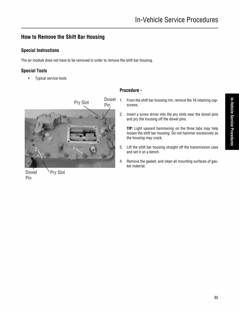
In-Vehicle Service Procedures
85
In-Vehicle Service Procedures
How to Remove the Shift Bar Housing
Special Instructions
The air module does not have to be removed in order to remove the shift bar housing.
Special Tools
• Typical service tools
Procedure -
1. From the shift bar housing rim, remove the 16 retaining cap-screws.
2. Insert a screw driver into the pry slots near the dowel pinsand pry the housing off the dowel pins.
TIP: Light upward hammering on the three tabs may helploosen the shift bar housing. Do not hammer excessively asthe housing may crack.
3. Lift the shift bar housing straight off the transmission caseand set it on a bench.
4. Remove the gasket, and clean all mounting surfaces of gas-ket material.
12
Pry SlotDowelPin
Pry SlotDowelPin

In-Vehicle Service Procedures
86
How to Remove the Oil Seal Mechanical/Magnetic Speedometer
Special Instructions
Prior to replacing the seal, carefully inspect the transmission to make sure the oil leakage is coming from the seal. Pay particularattention to the gasketed surfaces of the rear bearing cover, rear countershaft bearing covers, and shift bar housing.
For additional Information on rear seal service, refer to the “Seal Maintenance Guide” TCSM-0912.
Special Tools
• Output Yoke Puller T1
1. Bushing2. Rear Bearing Cover Assembly3. Capscrew4. Speedometer Drive Gear5. Oil Seal with Slinger6. O-Ring7. Speedometer Spacer Assembly
1. Rear Bearing Cover2. Sensor Retaining Capscrew3. O-Ring4. Speedometer Sensor5. Capscrew6. Oil Seal 7. Slinger8. O-Ring9. Speedometer Spacer Assembly10. Slinger
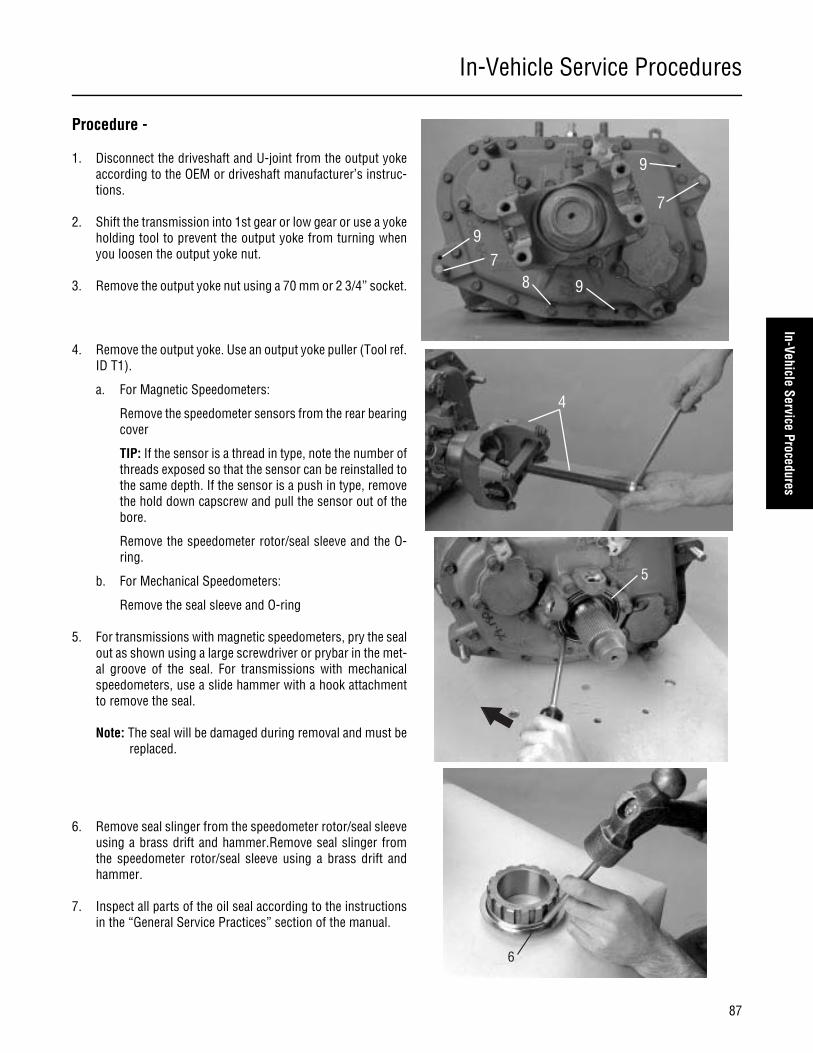
In-Vehicle Service Procedures
87
In-Vehicle Service Procedures
Procedure -
1. Disconnect the driveshaft and U-joint from the output yokeaccording to the OEM or driveshaft manufacturer’s instruc-tions.
2. Shift the transmission into 1st gear or low gear or use a yokeholding tool to prevent the output yoke from turning whenyou loosen the output yoke nut.
3. Remove the output yoke nut using a 70 mm or 2 3/4” socket.
4. Remove the output yoke. Use an output yoke puller (Tool ref.ID T1).
a. For Magnetic Speedometers:
Remove the speedometer sensors from the rear bearingcover
TIP: If the sensor is a thread in type, note the number ofthreads exposed so that the sensor can be reinstalled tothe same depth. If the sensor is a push in type, removethe hold down capscrew and pull the sensor out of thebore.
Remove the speedometer rotor/seal sleeve and the O-ring.
b. For Mechanical Speedometers:
Remove the seal sleeve and O-ring
5. For transmissions with magnetic speedometers, pry the sealout as shown using a large screwdriver or prybar in the met-al groove of the seal. For transmissions with mechanicalspeedometers, use a slide hammer with a hook attachmentto remove the seal.
Note: The seal will be damaged during removal and must bereplaced.
6. Remove seal slinger from the speedometer rotor/seal sleeveusing a brass drift and hammer.Remove seal slinger fromthe speedometer rotor/seal sleeve using a brass drift andhammer.
7. Inspect all parts of the oil seal according to the instructionsin the “General Service Practices” section of the manual.
7
7
8 9
9
9
4
5
6

In-Vehicle Service Procedures
88
How to Install the Oil Seal Mechanical/Magnetic Speedometer
Special Instructions
To prevent oil leaks, do not touch the seal lip, and make sure the seal driver is clean.
Special Tools
• Seal Driver Eaton K-2413
• Torque Wrench 500 lb. ft. capacity
Procedure -
1. Place a seal on the oil seal driver (Eaton # K-2413), and drivethe new seal into the rear bearing cover. The seal is fully in-stalled when the flange on the seal is flush with the shoulderin the bore.
2. Install the new slinger on speedometer rotor/seal sleeve us-ing a slinger driver.
1
2
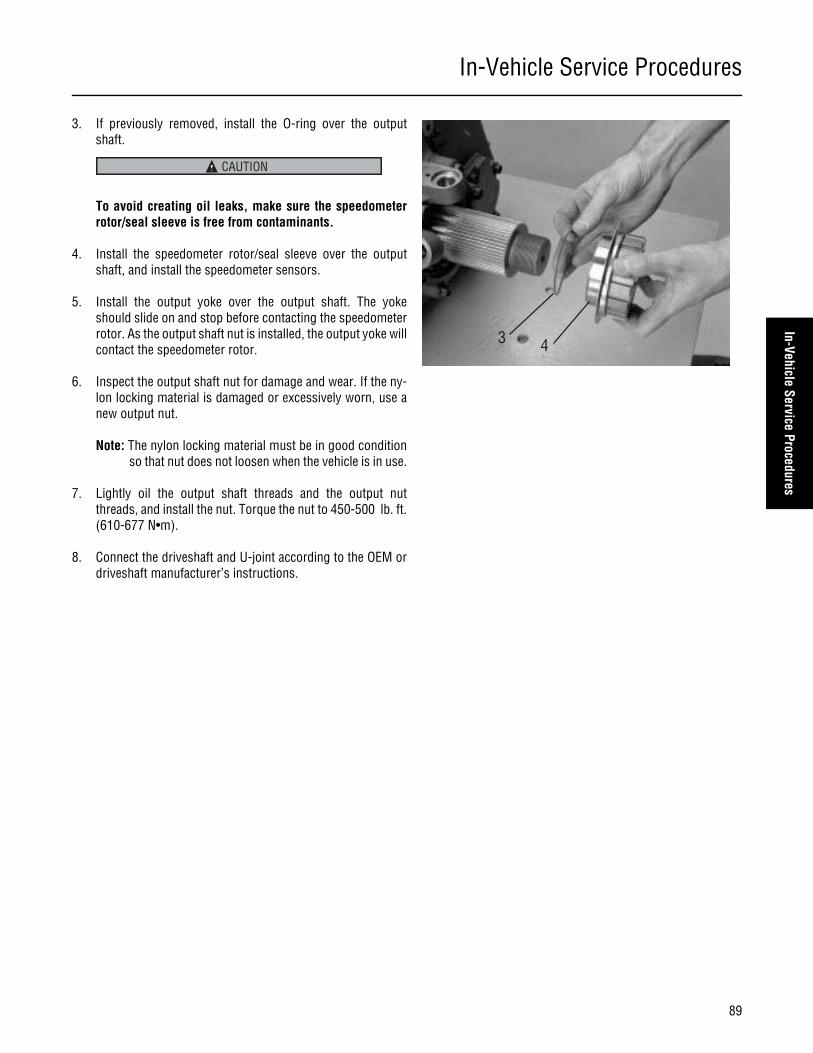
In-Vehicle Service Procedures
89
In-Vehicle Service Procedures
3. If previously removed, install the O-ring over the outputshaft.
To avoid creating oil leaks, make sure the speedometerrotor/seal sleeve is free from contaminants.
4. Install the speedometer rotor/seal sleeve over the outputshaft, and install the speedometer sensors.
5. Install the output yoke over the output shaft. The yokeshould slide on and stop before contacting the speedometerrotor. As the output shaft nut is installed, the output yoke willcontact the speedometer rotor.
6. Inspect the output shaft nut for damage and wear. If the ny-lon locking material is damaged or excessively worn, use anew output nut.
Note: The nylon locking material must be in good conditionso that nut does not loosen when the vehicle is in use.
7. Lightly oil the output shaft threads and the output nutthreads, and install the nut. Torque the nut to 450-500 lb. ft.(610-677 N•m).
8. Connect the driveshaft and U-joint according to the OEM ordriveshaft manufacturer’s instructions.
3 4
CAUTION

In-Vehicle Service Procedures
90
How to Remove the Auxiliary Section in Chassis
Special Instructions
The following procedure covers the removal of the auxiliary section with the transmission remaining in the chassis. If the trans-mission has been removed, refer to “Auxiliary Section Removal (Bench Procedure)” for removal procedures.
CAUTION: The lock cover was removed on new units, so the shiftbar needs to be removed to unlock the range cylinder and removethe auxiliary section.
Special Tools
• Floor Jack
• M10 x 1.5 tap
• Mounting Plate T19 (see Table 6)
Procedure -
1. Place the range selector on the shift knob in the down posi-tion to shift the transmission into low range. Removing theauxiliary section when the transmission is in Low Range willaid in reassembly.
2. Drain the transmission oil.
3. Disconnect the driveshaft and U-joint from the output yoke.
4. If the auxiliary section is to be disassembled, remove theoutput nut using a 70 mm or 2 3/4” socket. To prevent theoutput shaft from rotating while removing the nut, shift thetransmission to 1st gear or use a yoke holding tool.
If the shift bar housing is still installed, you MUST performsteps 5 and 6 if the lock cover is present. New designs nolonger use the lock cover and the shiftbar housing must beremoved for auxiliary section removal.
5. Remove the capscrews from the range bar lock cover, androtate the lock cover counterclockwise until the notch on thecover lines up with the unlock symbol.
Note: The left is the old style cover and the right is the newstyle cover.
Note: If the system still contains air pressure, greater forceis required to turn the lock cover.
6. Insert the right capscrew to secure the cover in the unlockposition.
Roadranger¨ Valve
Jam Nut
WARNING
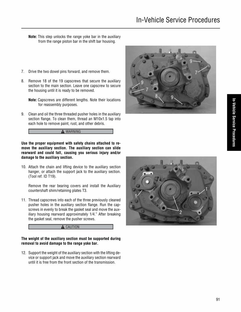
In-Vehicle Service Procedures
91
In-Vehicle Service Procedures
Note: This step unlocks the range yoke bar in the auxiliaryfrom the range piston bar in the shift bar housing.
7. Drive the two dowel pins forward, and remove them.
8. Remove 18 of the 19 capscrews that secure the auxiliarysection to the main section. Leave one capscrew to securethe housing until it is ready to be removed.
Note: Capscrews are different lengths. Note their locationsfor reassembly purposes.
9. Clean and oil the three threaded pusher holes in the auxiliarysection flange. To clean them, thread an M10x1.5 tap intoeach hole to remove paint, rust, and other debris.
Use the proper equipment with safety chains attached to re-move the auxiliary section. The auxiliary section can sliderearward and could fall, causing you serious injury and/ordamage to the auxiliary section.
10. Attach the chain and lifting device to the auxiliary sectionhanger, or attach the support jack to the auxiliary section.(Tool ref. ID T19).
Remove the rear bearing covers and install the Auxiliarycountershaft shim/retaining plates T3.
11. Thread capscrews into each of the three previously cleanedpusher holes in the auxiliary section flange. Run the cap-screws in evenly to break the gasket seal and move the aux-iliary housing rearward approximately 1/4.” After breakingthe gasket seal, remove the pusher screws.
The weight of the auxiliary section must be supported duringremoval to avoid damage to the range yoke bar.
12. Support the weight of the auxiliary section with the lifting de-vice or support jack and move the auxiliary section rearwarduntil it is free from the front section of the transmission.
7
7
8 9
9
9
WARNING
11
2
CAUTION

In-Vehicle Service Procedures
92
How to Install the Auxiliary Section in Chassis
Special Instructions
The lock cover was removed on new units, so the shiftbar housing must remain off during auxiliary assembly to attach therange cylinder.
Special Tools
• Floor Jack
• Torque Wrench 500 lb. ft. capacity
• Torque Wrench 100 lb. ft. capacity
• Mounting Plate (tool ref. ID T19)
• Auxiliary countershaft support tools T3
Procedure - 1. Install the countershaft support tools (Tool ref. ID T3) on the
auxiliary section countershafts to center and hold the coun-tershafts in position.
2. Install the output yoke over the output shaft. The yokeshould slide on and stop before contacting the speedometerrotor. As the output shaft nut is installed, the output yoke willcontact the speedometer rotor.
Note: To prevent the output shaft from rotating while install-ing the nut, place a clean shop rag in the gear mesh oruse a yoke holding tool.
Note: Due to chassis interference, it may not be possible toinstall the yoke at this step. However, the output shaftmust be drawn fully into position to prevent it fromsagging when the auxiliary section is installed in thechassis. If the chassis causes interference, the yokecan be temporarily installed to draw up the outputshaft and then removed before the auxiliary section isinstalled.
3. Use crocus cloth or a wire wheel to clean rust and paint fromthe dowel pins before installing them.
If the dowel pins are not installed in the main case to theproper depth in step 4, the auxiliary section will not prop-erly align with the main case and bearing or synchronizerfailure may occur.
4. Install the dowel pins into the main case so that 3/8”-1/2” ofthe shoulder is exposed.
CAUTION
11
2
Shoulder
43/8"-1/2"
CAUTION
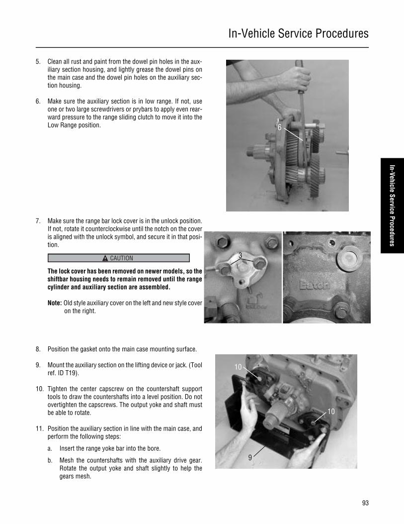
In-Vehicle Service Procedures
93
In-Vehicle Service Procedures
5. Clean all rust and paint from the dowel pin holes in the aux-iliary section housing, and lightly grease the dowel pins onthe main case and the dowel pin holes on the auxiliary sec-tion housing.
6. Make sure the auxiliary section is in low range. If not, useone or two large screwdrivers or prybars to apply even rear-ward pressure to the range sliding clutch to move it into theLow Range position.
7. Make sure the range bar lock cover is in the unlock position.If not, rotate it counterclockwise until the notch on the coveris aligned with the unlock symbol, and secure it in that posi-tion.
The lock cover has been removed on newer models, so theshiftbar housing needs to remain removed until the rangecylinder and auxiliary section are assembled.
Note: Old style auxiliary cover on the left and new style coveron the right.
8. Position the gasket onto the main case mounting surface.
9. Mount the auxiliary section on the lifting device or jack. (Toolref. ID T19).
10. Tighten the center capscrew on the countershaft supporttools to draw the countershafts into a level position. Do notovertighten the capscrews. The output yoke and shaft mustbe able to rotate.
11. Position the auxiliary section in line with the main case, andperform the following steps:
a. Insert the range yoke bar into the bore.
b. Mesh the countershafts with the auxiliary drive gear.Rotate the output yoke and shaft slightly to help thegears mesh.
6
CAUTION
9
10
10
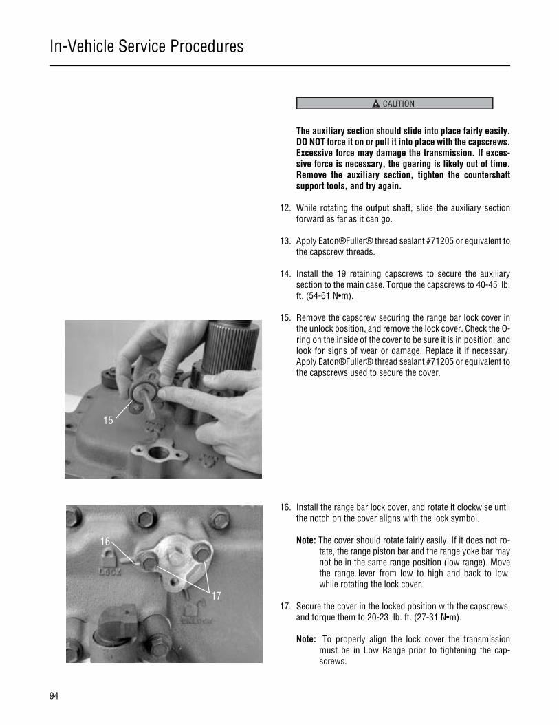
In-Vehicle Service Procedures
94
The auxiliary section should slide into place fairly easily.DO NOT force it on or pull it into place with the capscrews.Excessive force may damage the transmission. If exces-sive force is necessary, the gearing is likely out of time.Remove the auxiliary section, tighten the countershaftsupport tools, and try again.
12. While rotating the output shaft, slide the auxiliary sectionforward as far as it can go.
13. Apply Eaton®Fuller® thread sealant #71205 or equivalent tothe capscrew threads.
14. Install the 19 retaining capscrews to secure the auxiliarysection to the main case. Torque the capscrews to 40-45 lb.ft. (54-61 N•m).
15. Remove the capscrew securing the range bar lock cover inthe unlock position, and remove the lock cover. Check the O-ring on the inside of the cover to be sure it is in position, andlook for signs of wear or damage. Replace it if necessary.Apply Eaton®Fuller® thread sealant #71205 or equivalent tothe capscrews used to secure the cover.
16. Install the range bar lock cover, and rotate it clockwise untilthe notch on the cover aligns with the lock symbol.
Note: The cover should rotate fairly easily. If it does not ro-tate, the range piston bar and the range yoke bar maynot be in the same range position (low range). Movethe range lever from low to high and back to low,while rotating the lock cover.
17. Secure the cover in the locked position with the capscrews,and torque them to 20-23 lb. ft. (27-31 N•m).
Note: To properly align the lock cover the transmissionmust be in Low Range prior to tightening the cap-screws.
CAUTION
15
16
17

In-Vehicle Service Procedures
95
In-Vehicle Service Procedures
18. If the countershaft, countershaft bearings, or auxiliary hous-ing have been replaced, or if the countershafts, bearings, orshims were not marked and reassembled in the same loca-tion, the bearing endplay must be checked and set by shim-ming. Shim the countershaft bearings using the shimprocedure in Transmission Overhaul Procedure-Bench Ser-vice.
19. If shimming is not required, remove the support tools, andinstall the original shim in the proper location, new gasketand countershaft bearing cover. Secure the bearing coverswith the capscrews. Tighten the capscrews to 40-45 lb. ft.(54-61 N•m)
20. Connect the driveshaft and U-joint, and refill the transmis-sion with the recommended lubricant. For lubrication in-structions refer to the Lubrication section of this manual.

Transmission Overhaul Procedures-Bench Service
96
How to Disassemble the Integral Oil Cooler
Special Instructions
None
Special Tools
• Typical service tools
Procedure -
1. Remove capscrews retaining the internal cooler cover.
2. Remove the cooler cover taking care not to damage the steelbeaded gasket.
3. Loosen the cooler fittings from the cooler cover plate.

Transmission Overhaul Procedures-Bench Service
97
Transmission Overhaul
Procedures-Bench Service
4. Remove the capscrews retaining the rear of the cooler to thecover plate.

Transmission Overhaul Procedures-Bench Service
98
How to Assemble the Integral Oil Cooler
Special Instructions
None
Special Tools
• Typical service tools
Procedure -
1. Thoroughly clean the gasket surface of the transmissioncase and cover plate. Be sure the cooler fitting threads andflare seat are free of dirt and debris.
2. Install cooler to cover plate and tighten cooler fittings to 75lb. ft. (102 Nm).
3. Install capscrews to rear of cooler and tighten to 9-10 lb. ft.(12-14 Nm).
4. Install cooler cover plate gasket and cover plate. Install cap-screws and tighten to 40-45 lb. ft. (54-61 Nm).
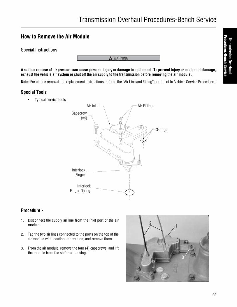
Transmission Overhaul Procedures-Bench Service
99
Transmission Overhaul
Procedures-Bench Service
How to Remove the Air Module
Special Instructions
A sudden release of air pressure can cause personal injury or damage to equipment. To prevent injury or equipment damage,exhaust the vehicle air system or shut off the air supply to the transmission before removing the air module.
Note: For air line removal and replacement instructions, refer to the “Air Line and Fitting” portion of In-Vehicle Service Procedures.
Special Tools
• Typical service tools
Procedure -
1. Disconnect the supply air line from the Inlet port of the airmodule.
2. Tag the two air lines connected to the ports on the top of theair module with location information, and remove them.
3. From the air module, remove the four (4) capscrews, and liftthe module from the shift bar housing.
WARNING
InterlockFinger O-ring
InterlockFinger
Air Fittings
O-rings
Capscrew(x4)
Air inlet
12
3
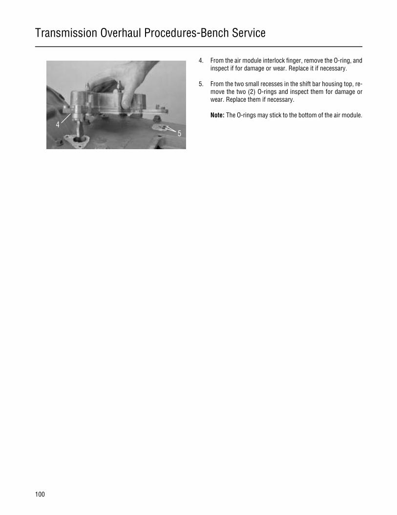
Transmission Overhaul Procedures-Bench Service
100
4. From the air module interlock finger, remove the O-ring, andinspect if for damage or wear. Replace it if necessary.
5. From the two small recesses in the shift bar housing top, re-move the two (2) O-rings and inspect them for damage orwear. Replace them if necessary.
Note: The O-rings may stick to the bottom of the air module.4
5
Transmission Overhaul Procedures-Bench Service
101
Transmission Overhaul
Procedures-Bench Service
How to Install the Air Module
Special Instructions
None
Special Tools
• Torque Wrench 25 lb. ft. Capacity
Procedure -
1. Clean all rust, paint, or other debris from the air modulemounting surfaces of the shift bar housing.
2. To help prevent corrosion between the aluminum air moduleand the cast iron shift bar housing, apply a light film of hightemperature grease to the air module mounting surfaces ofthe shift bar housing.
3. Lightly apply Eaton®Fuller® silicone lubricant #71206 orequivalent to all O-rings so a film covers the entire surfaceof each O-ring.
4. Install the large O-ring on the air module interlock fingerboss, and position the two (2) small O-rings in the recessesin the shift bar housing.
5. Position the air module on the shift bar housing.
6. Apply Eaton®Fuller® thread sealant #71205 or equivalent tothe four (4) retaining capscrews.
7. Install the four (4) retaining capscrews, and tighten them to20-23 lb. ft. (27-31 N•m) of torque.
8. Reconnect the air lines to the Inlet port and the other portson the top of the air module.
9. Return air to the system, and check for leaks.
2
24
5
4
7
88
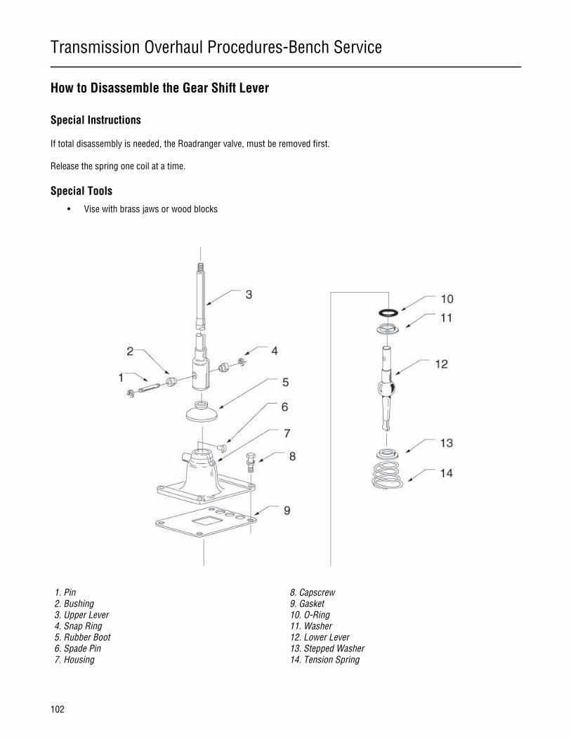
Transmission Overhaul Procedures-Bench Service
102
How to Disassemble the Gear Shift Lever
Special Instructions
If total disassembly is needed, the Roadranger valve, must be removed first.
Release the spring one coil at a time.
Special Tools
• Vise with brass jaws or wood blocks
1. Pin2. Bushing3. Upper Lever4. Snap Ring5. Rubber Boot6. Spade Pin7. Housing
8. Capscrew9. Gasket10. O-Ring11. Washer12. Lower Lever13. Stepped Washer14. Tension Spring

Transmission Overhaul Procedures-Bench Service
103
Transmission Overhaul
Procedures-Bench Service
Procedure -
1. On a non-isolated shift lever, remove the Roadranger valveusing the “How to Remove the Roadranger valve” instruc-tions in In-Vehicle Service Procedures. If the shift lever isequipped with a lever isolator, remove the snap ring, bush-ing, and cross pin to disconnect and remove the upper lever.
2. Slide the rubber boot up and off the shift lever shaft.
3. With housing bottom facing up, secure the assembly in avise.
4. Use large screwdriver to twist between the spring and hous-ing, forcing the spring from under the housing lugs one coilat a time.
5. From inside the housing tower, remove the tension spring,washer, and gear shift lever.
6. In models so equipped, from the housing bore, remove thenut and washer.
7. From the housing tower spade pin bore, remove and inspectthe spade pin, discard if damaged.
8. From the housing tower inside groove, inspect the O-ring,discard if damaged.

Transmission Overhaul Procedures-Bench Service
104
How to Assemble the Gear Shift Lever
Special Instructions
Inspect tension spring and washer for wear.
Apply Eaton rust preventative lubricant #71212 or equivalent to the shift lever pivot ball. A rust preventative lubricant film shouldcover all surfaces between and including the pivot ball.
Seat the tension spring one coil at a time.
Special Tools
• Vise with brass jaws or wood blocks
• Item T4: Tension Spring Driver (see Table 6)
1. Pin2. Bushing3. Upper Lever4. Snap Ring5. Rubber Boot6. Spade Pin7. Housing
8. Capscrew9. Gasket10. O-Ring11. Washer12. Lower Lever13. Stepped Washer14. Tension Spring
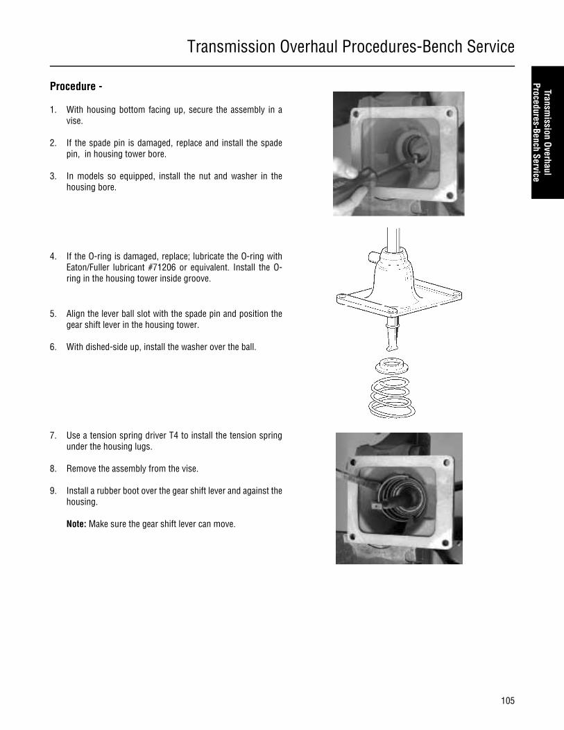
Transmission Overhaul Procedures-Bench Service
105
Transmission Overhaul
Procedures-Bench Service
Procedure -
1. With housing bottom facing up, secure the assembly in avise.
2. If the spade pin is damaged, replace and install the spadepin, in housing tower bore.
3. In models so equipped, install the nut and washer in thehousing bore.
4. If the O-ring is damaged, replace; lubricate the O-ring withEaton/Fuller lubricant #71206 or equivalent. Install the O-ring in the housing tower inside groove.
5. Align the lever ball slot with the spade pin and position thegear shift lever in the housing tower.
6. With dished-side up, install the washer over the ball.
7. Use a tension spring driver T4 to install the tension springunder the housing lugs.
8. Remove the assembly from the vise.
9. Install a rubber boot over the gear shift lever and against thehousing.
Note: Make sure the gear shift lever can move.
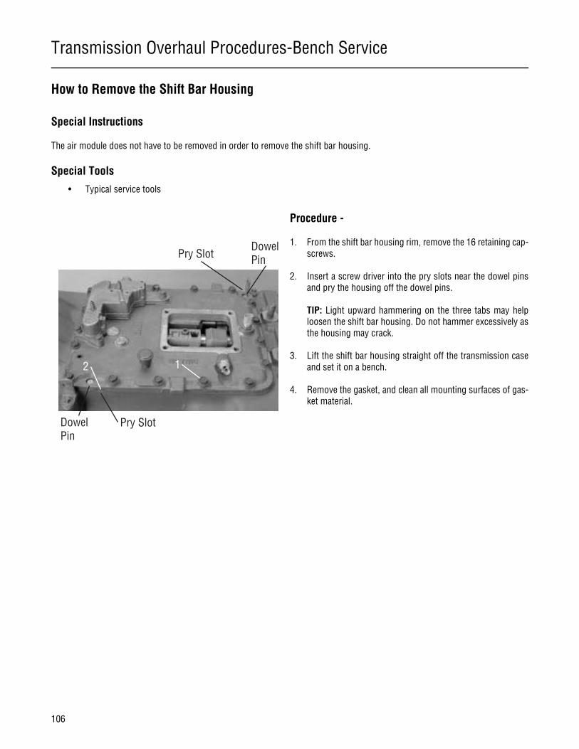
Transmission Overhaul Procedures-Bench Service
106
How to Remove the Shift Bar Housing
Special Instructions
The air module does not have to be removed in order to remove the shift bar housing.
Special Tools
• Typical service tools
Procedure -
1. From the shift bar housing rim, remove the 16 retaining cap-screws.
2. Insert a screw driver into the pry slots near the dowel pinsand pry the housing off the dowel pins.
TIP: Light upward hammering on the three tabs may helploosen the shift bar housing. Do not hammer excessively asthe housing may crack.
3. Lift the shift bar housing straight off the transmission caseand set it on a bench.
4. Remove the gasket, and clean all mounting surfaces of gas-ket material.
12
Pry SlotDowelPin
Pry SlotDowelPin
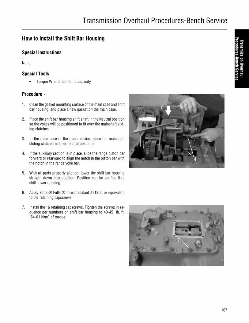
Transmission Overhaul Procedures-Bench Service
107
Transmission Overhaul
Procedures-Bench Service
How to Install the Shift Bar Housing
Special Instructions
None
Special Tools
• Torque Wrench 50 lb. ft. capacity
Procedure -
1. Clean the gasket mounting surface of the main case and shiftbar housing, and place a new gasket on the main case.
2. Place the shift bar housing shift shaft in the Neutral positionso the yokes will be positioned to fit over the mainshaft slid-ing clutches.
3. In the main case of the transmission, place the mainshaftsliding clutches in their neutral positions.
4. If the auxiliary section is in place, slide the range piston barforward or rearward to align the notch in the piston bar withthe notch in the range yoke bar.
5. With all parts properly aligned, lower the shift bar housingstraight down into position. Position can be verified thrushift tower opening.
6. Apply Eaton® Fuller® thread sealant #71205 or equivalentto the retaining capscrews.
7. Install the 16 retaining capscrews. Tighten the screws in se-quence per numbers on shift bar housing to 40-45 lb. ft.(54-61 N•m) of torque.
4
5
7
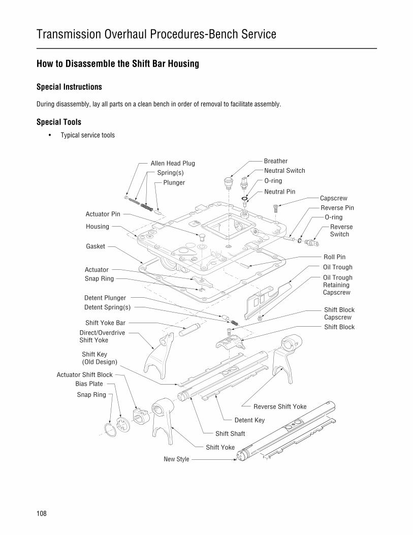
Transmission Overhaul Procedures-Bench Service
108
How to Disassemble the Shift Bar Housing
Special Instructions
During disassembly, lay all parts on a clean bench in order of removal to facilitate assembly.
Special Tools
• Typical service tools
Allen Head PlugSpring(s)
Plunger
BreatherNeutral Switch
Reverse Switch
Capscrew
Roll Pin
O-ring
Neutral Pin
O-ringReverse Pin
Oil Trough
Oil Trough Retaining Capscrew
Detent PlungerDetent Spring(s) Shift Block
Capscrew
Shift Block
Gasket
Direct/OverdriveShift Yoke
Shift Yoke Bar
Shift Key (Old Design)
Snap Ring
Bias PlateActuator Shift Block
Shift Yoke
Shift Shaft
Detent Key
Reverse Shift Yoke
ActuatorSnap Ring
Housing
Actuator Pin
New Style
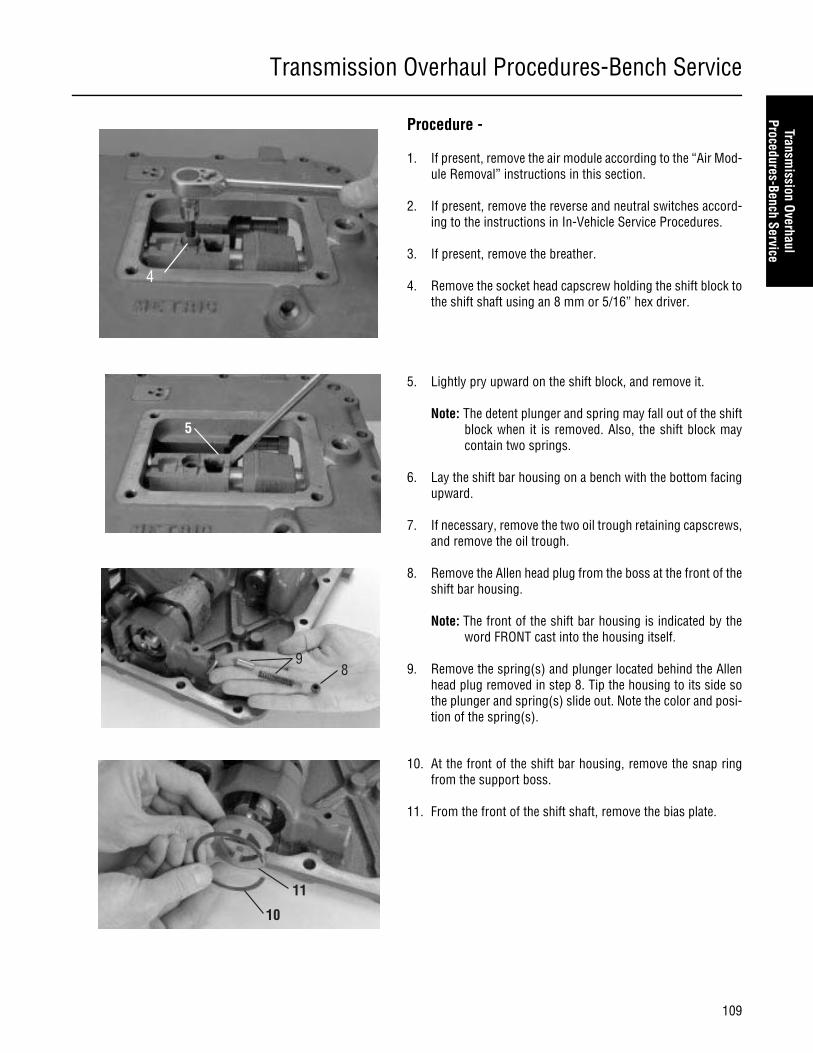
Transmission Overhaul Procedures-Bench Service
109
Transmission Overhaul
Procedures-Bench Service
Procedure -
1. If present, remove the air module according to the “Air Mod-ule Removal” instructions in this section.
2. If present, remove the reverse and neutral switches accord-ing to the instructions in In-Vehicle Service Procedures.
3. If present, remove the breather.
4. Remove the socket head capscrew holding the shift block tothe shift shaft using an 8 mm or 5/16” hex driver.
5. Lightly pry upward on the shift block, and remove it.
Note: The detent plunger and spring may fall out of the shiftblock when it is removed. Also, the shift block maycontain two springs.
6. Lay the shift bar housing on a bench with the bottom facingupward.
7. If necessary, remove the two oil trough retaining capscrews,and remove the oil trough.
8. Remove the Allen head plug from the boss at the front of theshift bar housing.
Note: The front of the shift bar housing is indicated by theword FRONT cast into the housing itself.
9. Remove the spring(s) and plunger located behind the Allenhead plug removed in step 8. Tip the housing to its side sothe plunger and spring(s) slide out. Note the color and posi-tion of the spring(s).
10. At the front of the shift bar housing, remove the snap ringfrom the support boss.
11. From the front of the shift shaft, remove the bias plate.
4
5
89
10
11
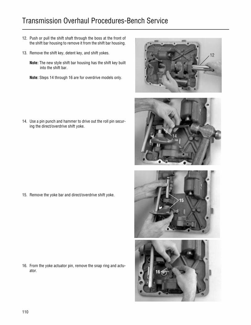
Transmission Overhaul Procedures-Bench Service
110
12. Push or pull the shift shaft through the boss at the front ofthe shift bar housing to remove it from the shift bar housing.
13. Remove the shift key, detent key, and shift yokes.
Note: The new style shift bar housing has the shift key builtinto the shift bar.
Note: Steps 14 through 16 are for overdrive models only.
14. Use a pin punch and hammer to drive out the roll pin secur-ing the direct/overdrive shift yoke.
15. Remove the yoke bar and direct/overdrive shift yoke.
16. From the yoke actuator pin, remove the snap ring and actu-ator.
12
14
15
16

Transmission Overhaul Procedures-Bench Service
111
Transmission Overhaul
Procedures-Bench Service
How to Disassemble the Range Cylinder
Special Instructions
Do not overstretch the snap ring in step 4. If it is overstretched, it must be replaced.
Special Tools
• Typical service tools
Procedure -
1. If not previously removed, remove the shift bar housing.
2. Remove the two (2) capscrews on the range cylinder cover.
3. Using a soft bar, tap the piston bar rearward to remove therange cylinder cover and piston assembly from the cylinder.
4. Remove the range piston snap ring and range piston fromthe piston bar.
5. Remove the three (3) O-rings on the cylinder cover and thesingle O-ring inside the range cylinder.
CAUTION
O-ring (Inside Range Cylinder)
Range PistonBar
Piston
Snap Ring
O-ring(Outer Cover)
O-ring(Inner Cover)
O-ring
Cover
Capscrew
1
5
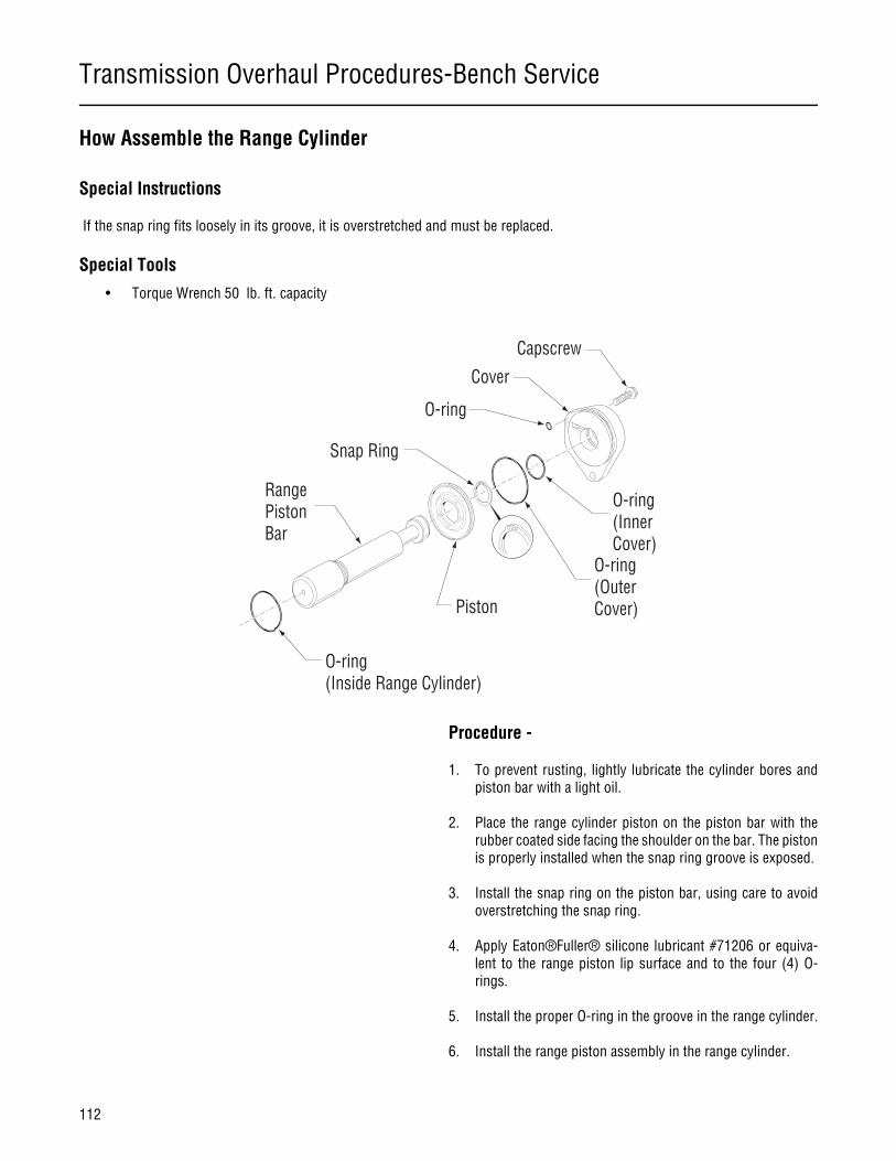
Transmission Overhaul Procedures-Bench Service
112
How Assemble the Range Cylinder
Special Instructions
If the snap ring fits loosely in its groove, it is overstretched and must be replaced.
Special Tools
• Torque Wrench 50 lb. ft. capacity
Procedure -
1. To prevent rusting, lightly lubricate the cylinder bores andpiston bar with a light oil.
2. Place the range cylinder piston on the piston bar with therubber coated side facing the shoulder on the bar. The pistonis properly installed when the snap ring groove is exposed.
3. Install the snap ring on the piston bar, using care to avoidoverstretching the snap ring.
4. Apply Eaton®Fuller® silicone lubricant #71206 or equiva-lent to the range piston lip surface and to the four (4) O-rings.
5. Install the proper O-ring in the groove in the range cylinder.
6. Install the range piston assembly in the range cylinder.
O-ring (Inside Range Cylinder)
Range PistonBar
Piston
Snap Ring
O-ring(Outer Cover)
O-ring(Inner Cover)
O-ring
Cover
Capscrew

Transmission Overhaul Procedures-Bench Service
113
Transmission Overhaul
Procedures-Bench Service
7. Install the proper O-ring in the groove on the inside of therange cylinder cover, and install the largest O-ring in thegroove on the outside of the range cylinder cover.
8. Place the smallest O-ring in the recess in the cover, and in-stall the cover.
9. Apply Eaton®Fuller® thread sealant #71205 or equivalent tothe retaining capscrews, and install the two (2) capscrewson the range cover. Tighten the capscrews to 20-23 lb. ft.(27-31 N•m) of torque.
7
8
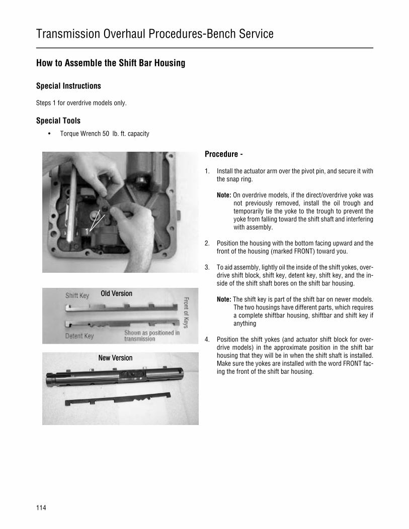
Transmission Overhaul Procedures-Bench Service
114
How to Assemble the Shift Bar Housing
Special Instructions
Steps 1 for overdrive models only.
Special Tools
• Torque Wrench 50 lb. ft. capacity
Procedure -
1. Install the actuator arm over the pivot pin, and secure it withthe snap ring.
Note: On overdrive models, if the direct/overdrive yoke wasnot previously removed, install the oil trough andtemporarily tie the yoke to the trough to prevent theyoke from falling toward the shift shaft and interferingwith assembly.
2. Position the housing with the bottom facing upward and thefront of the housing (marked FRONT) toward you.
3. To aid assembly, lightly oil the inside of the shift yokes, over-drive shift block, shift key, detent key, shift key, and the in-side of the shift shaft bores on the shift bar housing.
Note: The shift key is part of the shift bar on newer models.The two housings have different parts, which requiresa complete shiftbar housing, shiftbar and shift key ifanything
4. Position the shift yokes (and actuator shift block for over-drive models) in the approximate position in the shift barhousing that they will be in when the shift shaft is installed.Make sure the yokes are installed with the word FRONT fac-ing the front of the shift bar housing.
1
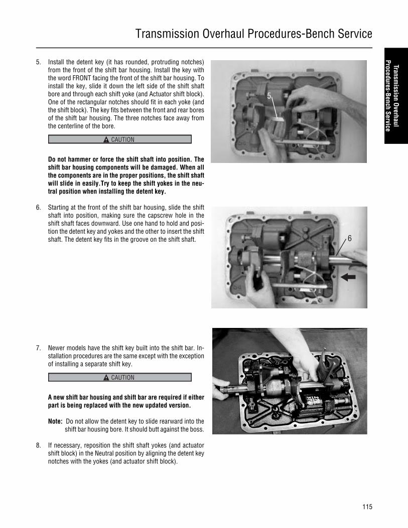
Transmission Overhaul Procedures-Bench Service
115
Transmission Overhaul
Procedures-Bench Service
5. Install the detent key (it has rounded, protruding notches)from the front of the shift bar housing. Install the key withthe word FRONT facing the front of the shift bar housing. Toinstall the key, slide it down the left side of the shift shaftbore and through each shift yoke (and Actuator shift block).One of the rectangular notches should fit in each yoke (andthe shift block). The key fits between the front and rear boresof the shift bar housing. The three notches face away fromthe centerline of the bore.
Do not hammer or force the shift shaft into position. Theshift bar housing components will be damaged. When allthe components are in the proper positions, the shift shaftwill slide in easily.Try to keep the shift yokes in the neu-tral position when installing the detent key.
6. Starting at the front of the shift bar housing, slide the shiftshaft into position, making sure the capscrew hole in theshift shaft faces downward. Use one hand to hold and posi-tion the detent key and yokes and the other to insert the shiftshaft. The detent key fits in the groove on the shift shaft.
7. Newer models have the shift key built into the shift bar. In-stallation procedures are the same except with the exceptionof installing a separate shift key.
A new shift bar housing and shift bar are required if eitherpart is being replaced with the new updated version.
Note: Do not allow the detent key to slide rearward into theshift bar housing bore. It should butt against the boss.
8. If necessary, reposition the shift shaft yokes (and actuatorshift block) in the Neutral position by aligning the detent keynotches with the yokes (and actuator shift block).
5
CAUTION
6
CAUTION
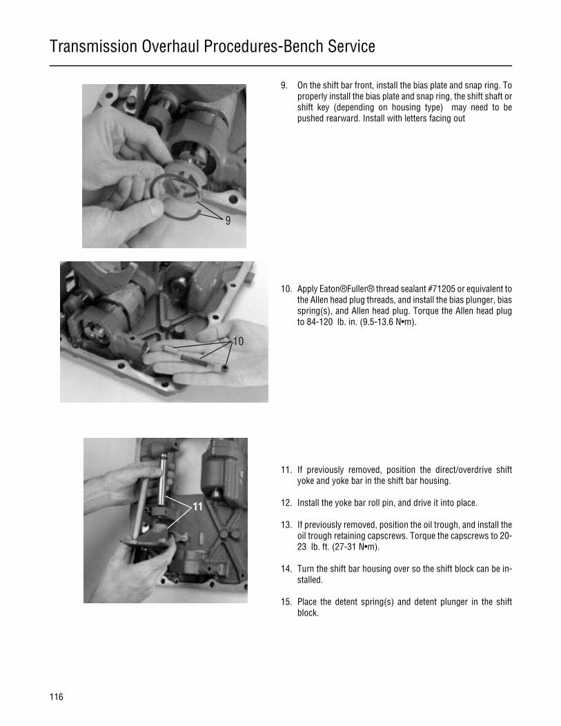
Transmission Overhaul Procedures-Bench Service
116
9. On the shift bar front, install the bias plate and snap ring. Toproperly install the bias plate and snap ring, the shift shaft orshift key (depending on housing type) may need to bepushed rearward. Install with letters facing out
10. Apply Eaton®Fuller® thread sealant #71205 or equivalent tothe Allen head plug threads, and install the bias plunger, biasspring(s), and Allen head plug. Torque the Allen head plugto 84-120 lb. in. (9.5-13.6 N•m).
11. If previously removed, position the direct/overdrive shiftyoke and yoke bar in the shift bar housing.
12. Install the yoke bar roll pin, and drive it into place.
13. If previously removed, position the oil trough, and install theoil trough retaining capscrews. Torque the capscrews to 20-23 lb. ft. (27-31 N•m).
14. Turn the shift bar housing over so the shift block can be in-stalled.
15. Place the detent spring(s) and detent plunger in the shiftblock.
9
10
11

Transmission Overhaul Procedures-Bench Service
117
Transmission Overhaul
Procedures-Bench Service
16. Place the shift block on the shift shaft using the followingprocedure:
a. Tilt the shift block so the plunger faces slightly upward.
b. Place the plunger in the center of the detent notch, andpress the plunger in to compress the spring(s).
c. While the spring(s) are compressed, roll the shift blockinto place on the shift shaft.
Note: The shift shaft and shift key may (depending on hous-ing type) require repositioning to allow the shift blockto fit into place.
17. Apply Eaton Fuller thread sealant #71205 or equivalent to thecapscrew. Install the shift block capscrew. Torque the screwto 40-45 lb. ft. (54-61 N•m).
18. Install the following components: reverse pin and switch,neutral pin and switch, breather, and air module.
16
OptionalSpringDesign
17
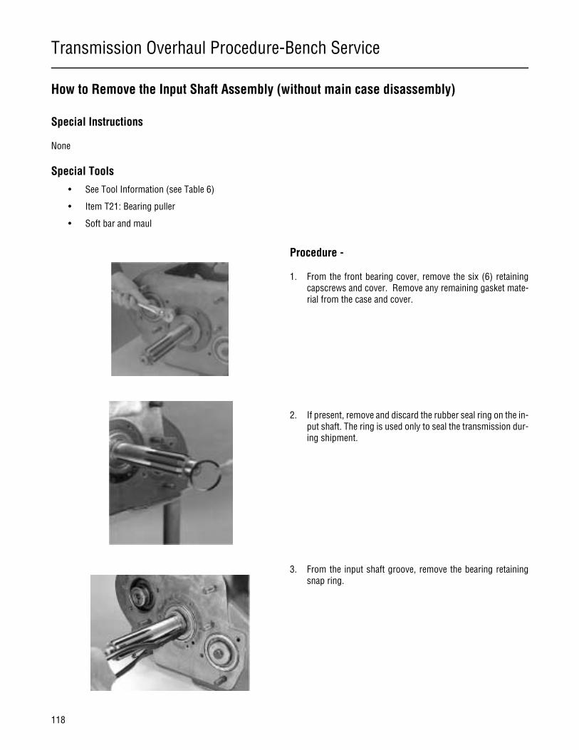
Transmission Overhaul Procedure-Bench Service
118
How to Remove the Input Shaft Assembly (without main case disassembly)
Special Instructions
None
Special Tools
• See Tool Information (see Table 6)
• Item T21: Bearing puller
• Soft bar and maul
Procedure -
1. From the front bearing cover, remove the six (6) retainingcapscrews and cover. Remove any remaining gasket mate-rial from the case and cover.
2. If present, remove and discard the rubber seal ring on the in-put shaft. The ring is used only to seal the transmission dur-ing shipment.
3. From the input shaft groove, remove the bearing retainingsnap ring.
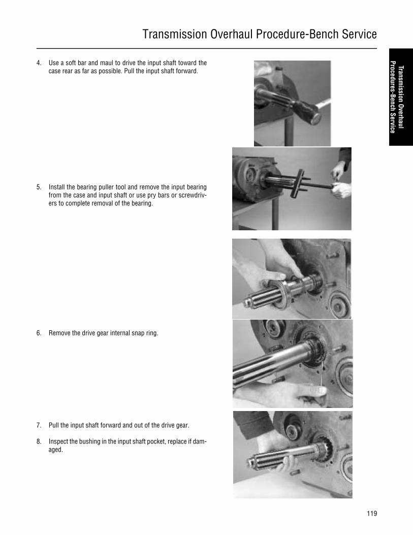
Transmission Overhaul Procedure-Bench Service
119
Transmission Overhaul
Procedures-Bench Service
4. Use a soft bar and maul to drive the input shaft toward thecase rear as far as possible. Pull the input shaft forward.
5. Install the bearing puller tool and remove the input bearingfrom the case and input shaft or use pry bars or screwdriv-ers to complete removal of the bearing.
6. Remove the drive gear internal snap ring.
7. Pull the input shaft forward and out of the drive gear.
8. Inspect the bushing in the input shaft pocket, replace if dam-aged.
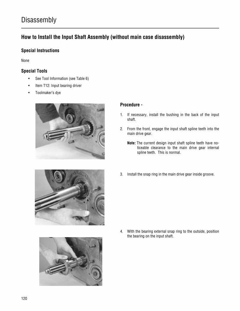
Disassembly
120
How to Install the Input Shaft Assembly (without main case disassembly)
Special Instructions
None
Special Tools
• See Tool Information (see Table 6)
• Item T12: Input bearing driver
• Toolmaker’s dye
Procedure -
1. If necessary, install the bushing in the back of the inputshaft.
2. From the front, engage the input shaft spline teeth into themain drive gear.
Note: The current design input shaft spline teeth have no-ticeable clearance to the main drive gear internalspline teeth. This is normal.
3. Install the snap ring in the main drive gear inside groove.
4. With the bearing external snap ring to the outside, positionthe bearing on the input shaft.

Disassembly
121
Transmission Overhaul
Procedures-Bench Service
5. Install the input shaft bearing over the input shaft. Use aflanged-end bearing driver which contacts both the bearinginner race and outer race. Drive the bearing until it contactsthe front case.
6. Install the input shaft retaining snap ring.
Note: Do not replace the small rubber lip seal. It is used onlyto prevent leakage during shipping.
7. Install the front bearing cover and torque the six capscrewsto specifications.
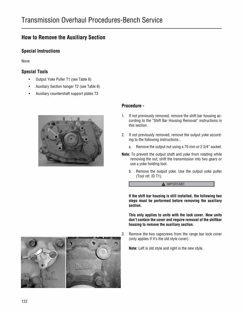
Transmission Overhaul Procedures-Bench Service
122
How to Remove the Auxiliary Section
Special Instructions
None
Special Tools
• Output Yoke Puller T1 (see Table 6)
• Auxiliary Section hanger T2 (see Table 6)
• Auxiliary countershaft support plates T3
Procedure -
1. If not previously removed, remove the shift bar housing ac-cording to the “Shift Bar Housing Removal” instructions inthis section.
2. If not previously removed, remove the output yoke accord-ing to the following instructions:.
a. Remove the output nut using a 70 mm or 2 3/4” socket.
Note: To prevent the output shaft and yoke from rotating whileremoving the nut, shift the transmission into two gears oruse a yoke holding tool.
b. Remove the output yoke. Use the output yoke puller(Tool ref. ID T1).
If the shift bar housing is still installed, the following twosteps must be performed before removing the auxiliarysection.
This only applies to units with the lock cover. New unitsdon’t contain the cover and require removal of the shiftbarhousing to remove the auxiliary section.
3. Remove the two capscrews from the range bar lock cover(only applies if it’s the old style cover).
Note: Left is old style and right is the new style.
2
IMPORTANT
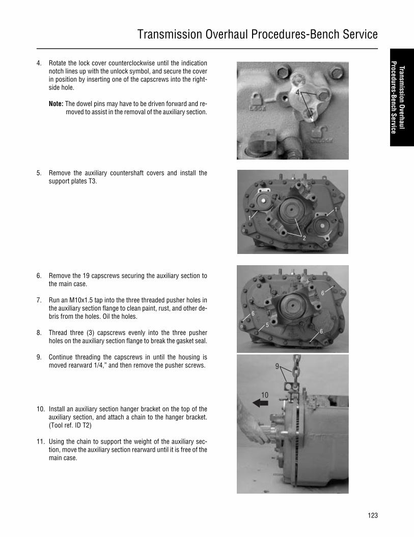
Transmission Overhaul Procedures-Bench Service
123
Transmission Overhaul
Procedures-Bench Service
4. Rotate the lock cover counterclockwise until the indicationnotch lines up with the unlock symbol, and secure the coverin position by inserting one of the capscrews into the right-side hole.
Note: The dowel pins may have to be driven forward and re-moved to assist in the removal of the auxiliary section.
5. Remove the auxiliary countershaft covers and install thesupport plates T3.
6. Remove the 19 capscrews securing the auxiliary section tothe main case.
7. Run an M10x1.5 tap into the three threaded pusher holes inthe auxiliary section flange to clean paint, rust, and other de-bris from the holes. Oil the holes.
8. Thread three (3) capscrews evenly into the three pusherholes on the auxiliary section flange to break the gasket seal.
9. Continue threading the capscrews in until the housing ismoved rearward 1/4,” and then remove the pusher screws.
10. Install an auxiliary section hanger bracket on the top of theauxiliary section, and attach a chain to the hanger bracket.(Tool ref. ID T2)
11. Using the chain to support the weight of the auxiliary sec-tion, move the auxiliary section rearward until it is free of themain case.
4
11
2
6
6
6
5
9
10

Transmission Overhaul Procedures-Bench Service
124
How to Disassemble the Auxiliary Section
Special Instructions
None
Special Tools
• Typical service tools
1. Speedometer Rotor Assembly2. O-Ring3. Oil Seal Kit4. Capscrew5. Rear Bearing Cover Assembly6. Gasket7. Capscrew8. Capscrew9. Cover10 Gasket11. Shim Kit12. Lifting Eye Kit13. Rear Housing Assembly14. Gasket
15. Capscrew16. O-Ring17. Range Bar Cover Assembly18. Screw19. Speedometer Drive Gear20. Speedometer Spacer Assembly21. Oil Seal with Slinger22. Screw23. Speedometer Sensor Kit24. Slinger25. O-Ring26. Rear Bearing Cover Assembly27. Plug Retaining Kit28. Lifting Kit29. Capscrew
15
16
6
8
9
10
11
13
14
18
OEM supplied non-adjustable speedometer sensor(Non-Threaded)
OEM supplied adjustable
speedometer sensor
(Threaded)
17
26
22
21
2
20
19
27
5
4
7
3
2
124
23
25
12
29
28
12 2928
Old Design
Old Design
Mechanical
Magnetic
Old Design

Transmission Overhaul Procedures-Bench Service
125
Transmission Overhaul
Procedures-Bench Service
Procedure -
1. Mount the auxiliary section in a vise with brass jaw protec-tors. (The jaw protectors will prevent damage to the auxiliarysection flange.)
Note: If the auxiliary countershafts, countershaft bearings,bearing races, bearing shims, auxiliary section hous-ing, and main case will be reused, remove one of thecountershaft bearing covers and mark the parts as up-per shaft or lower shaft. Then if the countershafts arereassembled with all parts in their original positions,the original shims can be reused, and re-shimmingwill not be required.
2. If not previously removed, remove the output yoke nut andoutput yoke. To remove the nut, use a large air impactwrench or a breaker bar and a 70 mm or 2 3/4” socket. Toprevent the output shaft from turning, place a shop rag in thegear mesh or use a yoke holding tool. Use a yoke puller (Toolref. ID T1) to remove the yoke.
3. Mark the output bearing cover and the rear of the housing insuch a way that you will know what position to install thebearing cover later. The cover can be installed in two oppo-site positions.
4. Remove the speedometer rotor/seal sleeve.
5. Remove the O-ring from the output shaft.
As you move the output shaft forward, the auxiliarycounter shafts may fall out of the auxiliary section housingcausing personal injury or damage to the countershafts.
6. Using a maul, move the output shaft forward far enough toremove the auxiliary countershafts.
7. Remove the range synchronizer assembly and range yokeassembly from the output shaft.
8. Continue moving the output shaft assembly forward until itis free of the auxiliary section housing.
9. Remove the four (4) capscrews from each of the auxiliaryhousing countershaft rear bearing covers.
10. From each auxiliary countershaft, remove the auxiliary coun-tershaft rear bearing cover, gasket, and shim.
11. Remove the auxiliary countershaft bearing races.
3Tip
4
WARNING
6
Transmission Overhaul Procedures-Bench Service
126
12. From the auxiliary housing back, remove the capscrews se-curing the lock cover.
13. Remove the lock cover and remove the O-ring from the cov-er.
14. From the auxiliary housing rear, remove the output bearingretaining capscrews and cover.
15. To remove the output seal, drive the seal out the rear of theoutput bearing cover with a hammer and drift.
16. Remove the output bearing and bearing cup.
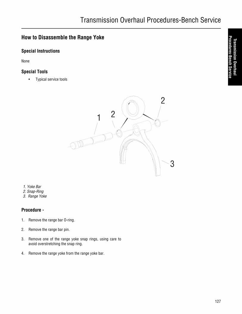
Transmission Overhaul Procedures-Bench Service
127
Transmission Overhaul
Procedures-Bench Service
How to Disassemble the Range Yoke
Special Instructions
None
Special Tools
• Typical service tools
Procedure -
1. Remove the range bar O-ring.
2. Remove the range bar pin.
3. Remove one of the range yoke snap rings, using care toavoid overstretching the snap ring.
4. Remove the range yoke from the range yoke bar.
1. Yoke Bar2. Snap-Ring3. Range Yoke
1 2
2
3

Transmission Overhaul Procedures-Bench Service
128
How to Disassemble the Output Shaft
Special Instructions
None
Special Tools
• Press
Procedure -
1. From the output shaft, remove the output bearing innerspacer.
2. Using the output shaft assembly gear front face as a base,press the output shaft through the bearing and gear.
Output ShaftFlat Washer
Auxiliary Mainshaft Reduction Gear
Stepped Washer
Bearing
Bearing Inner Spacer
2
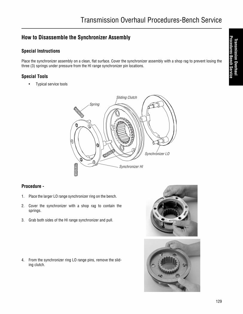
Transmission Overhaul Procedures-Bench Service
129
Transmission Overhaul
Procedures-Bench Service
How to Disassemble the Synchronizer Assembly
Special Instructions
Place the synchronizer assembly on a clean, flat surface. Cover the synchronizer assembly with a shop rag to prevent losing thethree (3) springs under pressure from the HI range synchronizer pin locations.
Special Tools
• Typical service tools
Procedure -
1. Place the larger LO range synchronizer ring on the bench.
2. Cover the synchronizer with a shop rag to contain thesprings.
3. Grab both sides of the HI range synchronizer and pull.
4. From the synchronizer ring LO range pins, remove the slid-ing clutch.
Spring
Sliding Clutch
Synchronizer LO
Synchronizer HI
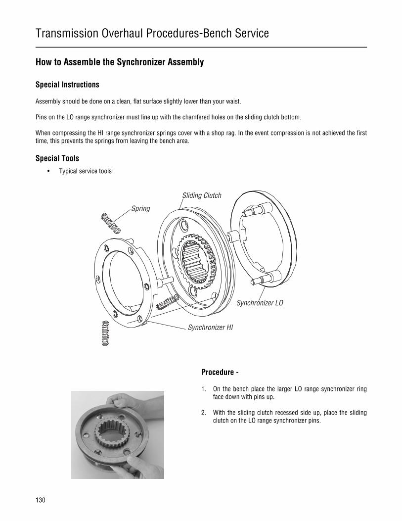
Transmission Overhaul Procedures-Bench Service
130
How to Assemble the Synchronizer Assembly
Special Instructions
Assembly should be done on a clean, flat surface slightly lower than your waist.
Pins on the LO range synchronizer must line up with the chamfered holes on the sliding clutch bottom.
When compressing the HI range synchronizer springs cover with a shop rag. In the event compression is not achieved the firsttime, this prevents the springs from leaving the bench area.
Special Tools
• Typical service tools
Procedure -
1. On the bench place the larger LO range synchronizer ringface down with pins up.
2. With the sliding clutch recessed side up, place the slidingclutch on the LO range synchronizer pins.
Spring
Sliding Clutch
Synchronizer LO
Synchronizer HI
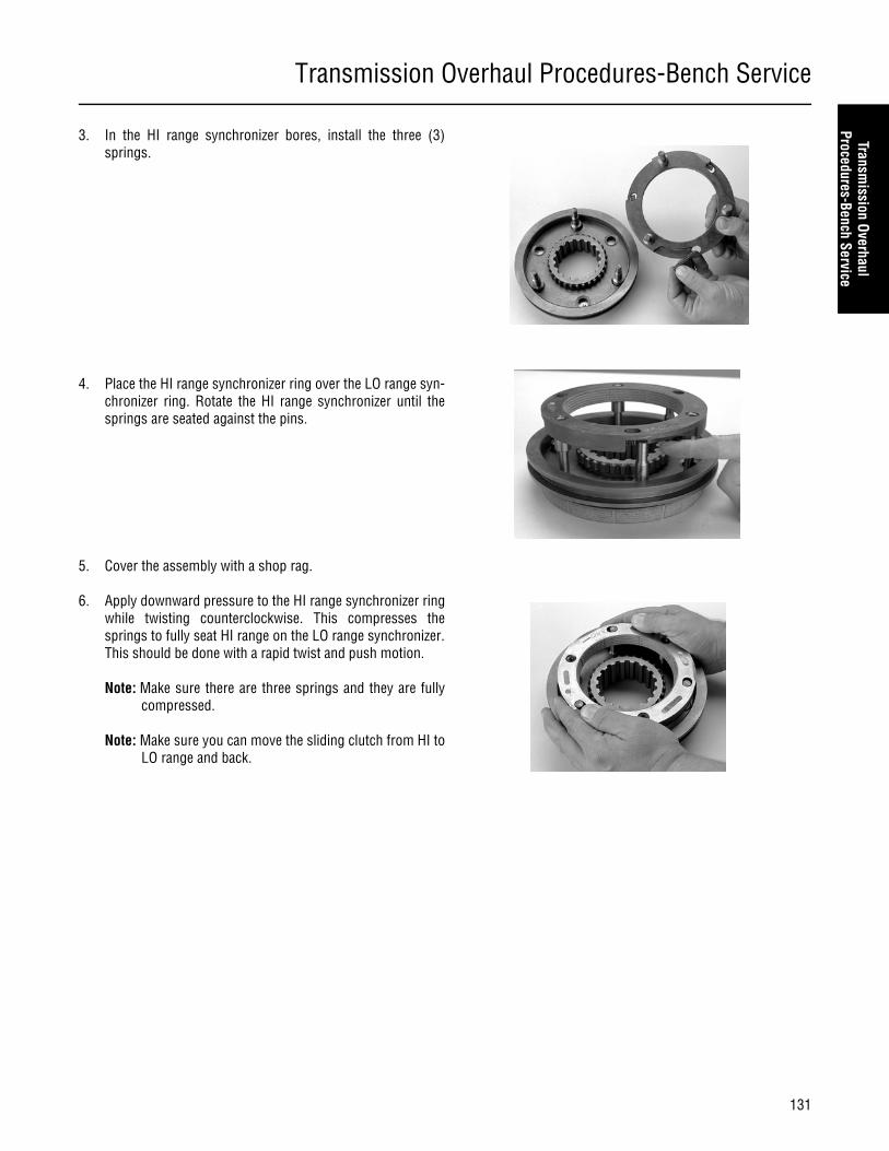
Transmission Overhaul Procedures-Bench Service
131
Transmission Overhaul
Procedures-Bench Service
3. In the HI range synchronizer bores, install the three (3)springs.
4. Place the HI range synchronizer ring over the LO range syn-chronizer ring. Rotate the HI range synchronizer until thesprings are seated against the pins.
5. Cover the assembly with a shop rag.
6. Apply downward pressure to the HI range synchronizer ringwhile twisting counterclockwise. This compresses thesprings to fully seat HI range on the LO range synchronizer.This should be done with a rapid twist and push motion.
Note: Make sure there are three springs and they are fullycompressed.
Note: Make sure you can move the sliding clutch from HI toLO range and back.

Transmission Overhaul Procedures-Bench Service
132
How to Remove the Clutch Housing
Special Instructions
None
Special Tools
• Typical service tools
Procedure -
1. From inside the clutch housing, remove the six (6) nuts andwashers.
2. From inside the clutch housing, remove the four (4) cap-screws.
3. Jar the clutch housing with a soft mallet to break the gasketseal.
4. Pull the clutch housing from the studs and transmissioncase.
5. Remove the gasket and clean the gasket mounting surfaceson the clutch housing and main case.
Main Case
Gasket
ClutchHousing
Cap Screw(x4)
Washer (x6)
Nut (x6 )
Stud
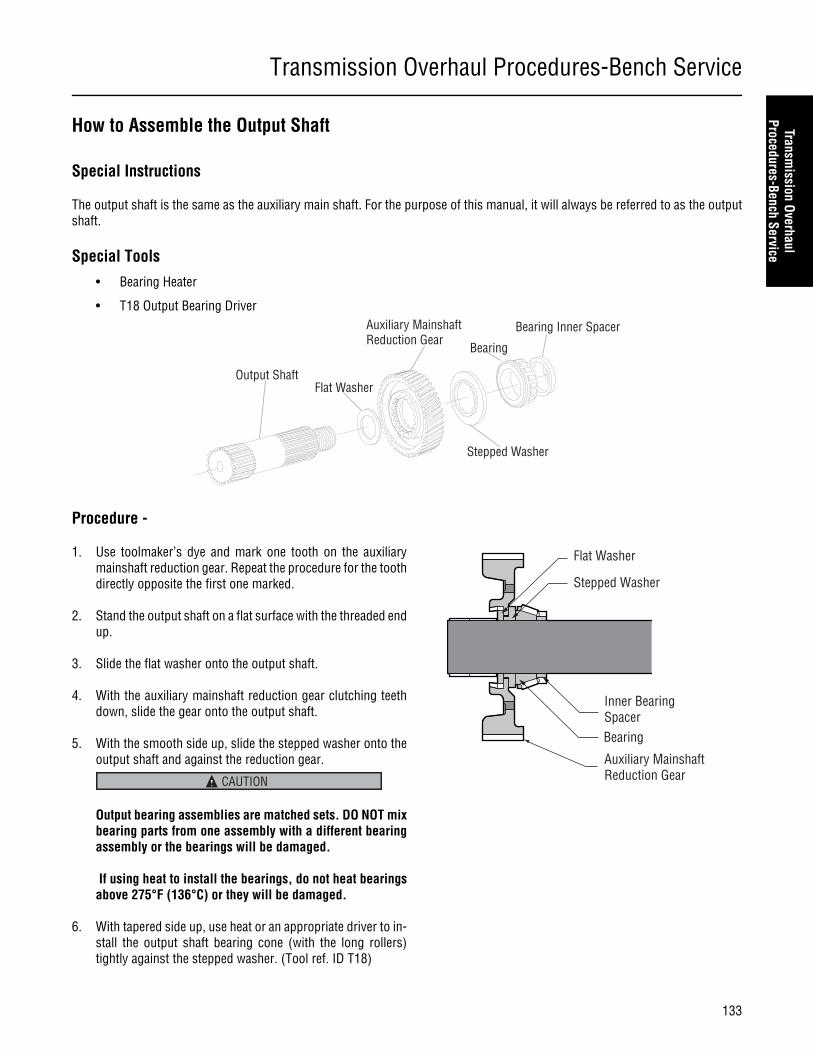
Transmission Overhaul Procedures-Bench Service
133
Transmission Overhaul
Procedures-Bench Service
How to Assemble the Output Shaft
Special Instructions
The output shaft is the same as the auxiliary main shaft. For the purpose of this manual, it will always be referred to as the outputshaft.
Special Tools
• Bearing Heater
• T18 Output Bearing Driver
Procedure -
1. Use toolmaker’s dye and mark one tooth on the auxiliarymainshaft reduction gear. Repeat the procedure for the toothdirectly opposite the first one marked.
2. Stand the output shaft on a flat surface with the threaded endup.
3. Slide the flat washer onto the output shaft.
4. With the auxiliary mainshaft reduction gear clutching teethdown, slide the gear onto the output shaft.
5. With the smooth side up, slide the stepped washer onto theoutput shaft and against the reduction gear.
Output bearing assemblies are matched sets. DO NOT mixbearing parts from one assembly with a different bearingassembly or the bearings will be damaged.
If using heat to install the bearings, do not heat bearingsabove 275°F (136°C) or they will be damaged.
6. With tapered side up, use heat or an appropriate driver to in-stall the output shaft bearing cone (with the long rollers)tightly against the stepped washer. (Tool ref. ID T18)
Output ShaftFlat Washer
Auxiliary Mainshaft Reduction Gear
Stepped Washer
Bearing
Bearing Inner Spacer
Flat Washer
Stepped Washer
Inner BearingSpacerBearing
Auxiliary MainshaftReduction GearCAUTION

Transmission Overhaul Procedures-Bench Service
134
7. Place the bearing inner spacer on the output shaft.

Transmission Overhaul Procedures-Bench Service
135
Transmission Overhaul
Procedures-Bench Service
How to Assemble the Range Yoke
Special Instructions
None
Special Tools
• Typical service tools
Procedure -
1. Install the range yoke on the range yoke bar. The flat side ofthe range yoke should be toward the notched end of therange yoke bar.
2. Install the range yoke snap rings in the grooves on each sideof the range yoke. Make sure the snap rings fit tightly and arenot overstretched. If they are loose, replace them.
3. Install the round pin in the range yoke bar.
4. Install the range yoke bar O-ring in its groove to hold the pinin place.
1 2
2
3
1
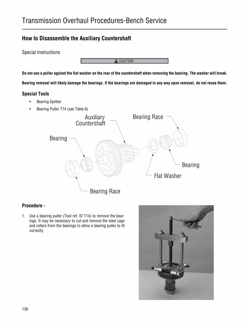
Transmission Overhaul Procedures-Bench Service
136
How to Disassemble the Auxiliary Countershaft
Special Instructions
Do not use a puller against the flat washer on the rear of the countershaft when removing the bearing. The washer will break.
Bearing removal will likely damage the bearings. If the bearings are damaged in any way upon removal, do not reuse them.
Special Tools
• Bearing Splitter
• Bearing Puller T14 (see Table 6)
Procedure -
1. Use a bearing puller (Tool ref. ID T14) to remove the bear-ings. It may be necessary to cut and remove the steel cageand rollers from the bearings to allow a bearing puller to fitcorrectly.
CAUTION
Bearing
Bearing Race
AuxiliaryCountershaft
Flat Washer
Bearing
Bearing Race

Transmission Overhaul Procedures-Bench Service
137
Transmission Overhaul
Procedures-Bench Service
How to Remove the Auxiliary Countershaft Bearing Races
Special Instructions
None
Special Tools
• Bearing Race Puller T16 (see Table 6)
Procedure -
1. Attach a bearing race puller (Tool ref. ID T16) as shown.
2. Pull the bearing races from the main case.
1
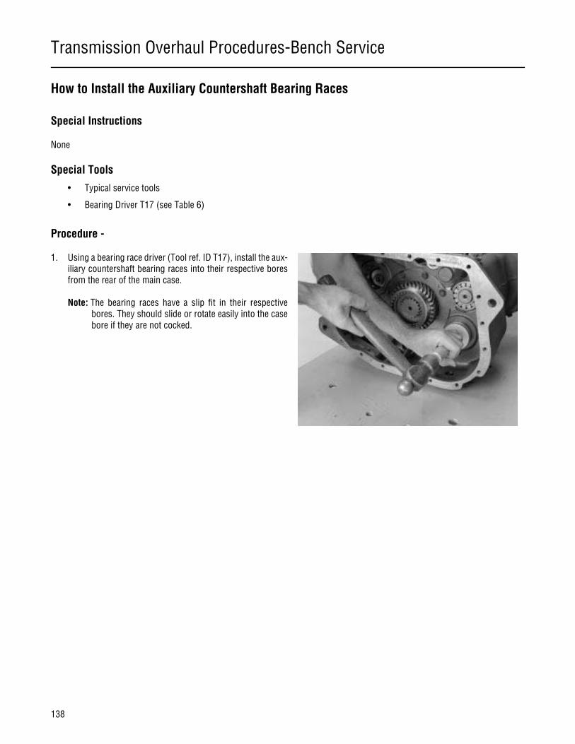
Transmission Overhaul Procedures-Bench Service
138
How to Install the Auxiliary Countershaft Bearing Races
Special Instructions
None
Special Tools
• Typical service tools
• Bearing Driver T17 (see Table 6)
Procedure -
1. Using a bearing race driver (Tool ref. ID T17), install the aux-iliary countershaft bearing races into their respective boresfrom the rear of the main case.
Note: The bearing races have a slip fit in their respectivebores. They should slide or rotate easily into the casebore if they are not cocked.

Transmission Overhaul Procedures-Bench Service
139
Transmission Overhaul
Procedures-Bench Service
How to Assemble the Auxiliary Countershaft
Special Instructions
None
Special Tools
• Bearing Driver T15 (see Table 6)
Procedure -
1. Install a washer on the rear of the countershaft.
2. Using a bearing driver (Tool ref. ID T15), drive a new bearingonto the rear of the countershaft. Make sure the driver con-tacts the inner race only.
3. Using a bearing driver (Tool ref. ID T15), drive a new bearingonto the front of the countershaft.
Bearing
Bearing Race
AuxiliaryCountershaft
Flat Washer
Bearing
Bearing Race
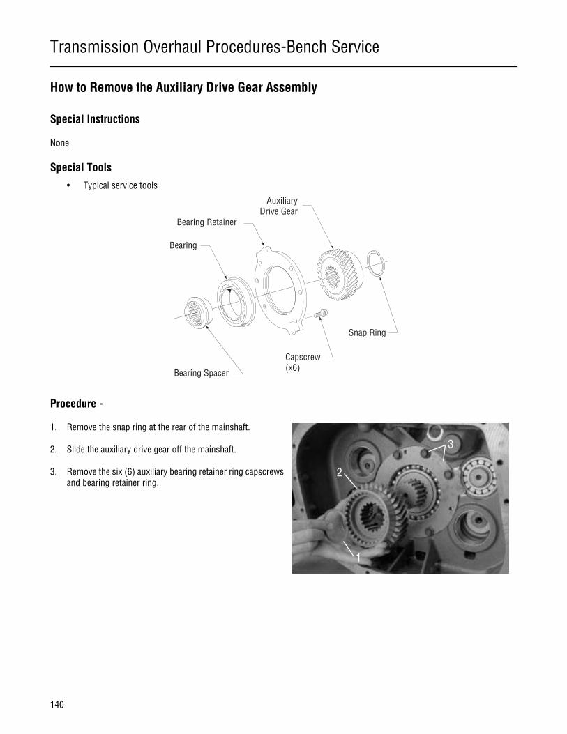
Transmission Overhaul Procedures-Bench Service
140
How to Remove the Auxiliary Drive Gear Assembly
Special Instructions
None
Special Tools
• Typical service tools
Procedure -
1. Remove the snap ring at the rear of the mainshaft.
2. Slide the auxiliary drive gear off the mainshaft.
3. Remove the six (6) auxiliary bearing retainer ring capscrewsand bearing retainer ring.
Bearing Spacer
Bearing
Bearing Retainer
Capscrew(x6)
AuxiliaryDrive Gear
Snap Ring
1
2
3
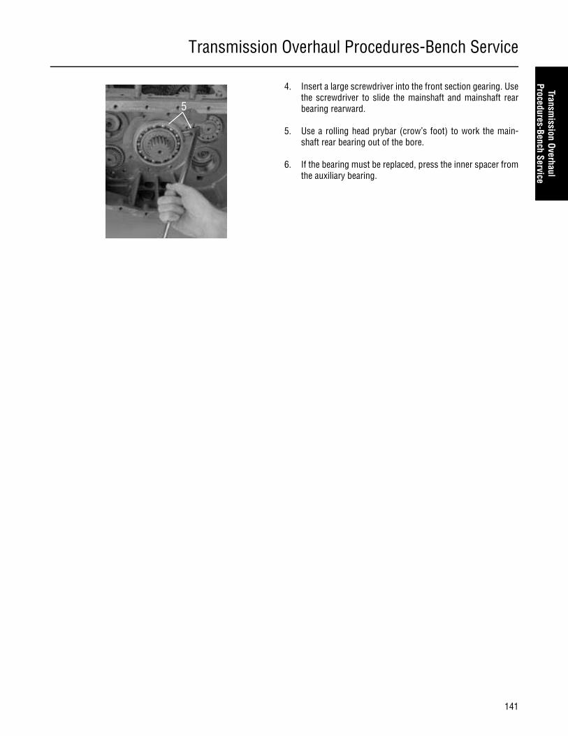
Transmission Overhaul Procedures-Bench Service
141
Transmission Overhaul
Procedures-Bench Service
4. Insert a large screwdriver into the front section gearing. Usethe screwdriver to slide the mainshaft and mainshaft rearbearing rearward.
5. Use a rolling head prybar (crow’s foot) to work the main-shaft rear bearing out of the bore.
6. If the bearing must be replaced, press the inner spacer fromthe auxiliary bearing.
5

Transmission Overhaul Procedures-Bench Service
142
How to Disassemble the Upper and Lower Reverse Idler Gear Assembly
Special Instructions
The new reverse idler shaft uses a snap-ring on the front in place of the capscrew.
Lower reverse idler gear removal is the same, but the mainshaft and countershafts must be removed.
Special Tools
• Slide Hammer T5 (see Table 6)
Procedure -
1. Remove the capscrew (or nut) on the front of the reverseidler shaft.
Note: If idler shaft spins, place a large screwdriver betweenreverse idler boss to keep shaft from spinning.
2. (On new design idler shafts remove the snap ring).
Previous Design
Slotted Thrust Washer
InnerRace
Notched ThrustWasher
BearingReverseIdler Gear
Reverse IdlerShaft
Snap Ring
CapscrewWasher
Current Design
Slotted Thrust Washer
InnerRace
Notched ThrustWasher
BearingReverseIdler Gear
Reverse IdlerShaft
Snap Ring
Snap RingWasher

Transmission Overhaul Procedures-Bench Service
143
Transmission Overhaul
Procedures-Bench Service
3. Thread a slide hammer puller (Tool ref. ID T5) into the rearof the reverse idler shaft. The threads are M12x1.75.
Note: Not all shafts styles had threads.
4. Using the slide hammer, remove the reverse idler shaft.
Note: If a slide hammer is not available, the reverse idler canbe driven out as shown in the photo.
Note: While removing the reverse idler shaft, the lube spac-er and washer can drop to the transmission case bot-tom.
Note: If desired, the upper reverse idler gear can be removedwithout removing the mainshaft. To do so, remove thesnap ring from the mainshaft reverse gear, and movethe mainshaft reverse gear forward.
2
3
Tip
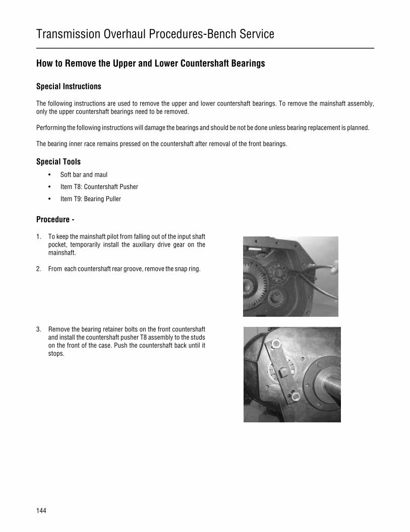
Transmission Overhaul Procedures-Bench Service
144
How to Remove the Upper and Lower Countershaft Bearings
Special Instructions
The following instructions are used to remove the upper and lower countershaft bearings. To remove the mainshaft assembly,only the upper countershaft bearings need to be removed.
Performing the following instructions will damage the bearings and should be not be done unless bearing replacement is planned.
The bearing inner race remains pressed on the countershaft after removal of the front bearings.
Special Tools
• Soft bar and maul
• Item T8: Countershaft Pusher
• Item T9: Bearing Puller
Procedure -
1. To keep the mainshaft pilot from falling out of the input shaftpocket, temporarily install the auxiliary drive gear on themainshaft.
2. From each countershaft rear groove, remove the snap ring.
3. Remove the bearing retainer bolts on the front countershaftand install the countershaft pusher T8 assembly to the studson the front of the case. Push the countershaft back until itstops.
Transmission Overhaul Procedures-Bench Service
145
Transmission Overhaul
Procedures-Bench Service
4. Use a bearing puller to remove the rear bearing from thecountershaft.
Damage will likely occur to this bearing during removal. Itis strongly recommended that this bearing is discarded.
5. Remove tool T8 from front of countershaft.
6. Return to the case rear, and drive each countershaft forwardas far as possible. This exposes the external snap ring.
7. Use the appropriate bearing puller T9 to remove the counter-shaft front bearings.
CAUTION
Transmission Overhaul Procedures-Bench Service
146
How to Remove the Mainshaft Assembly
Special Instructions
If transmission service will be limited to removal of the mainshaft, the input shaft does not need to be removed, but it must bemoved forward to provide enough clearance to remove the mainshaft.
Special Tools
• Item T8: Countershaft Pusher
• Item T9: Bearing Puller
• Mainshaft Hook Tool T20 (see Table)
Procedure -
1. Remove the six (6) capscrews retaining the input bearingcover, and remove the cover as shown in the explode view.
2. Grasp the input shaft and pull it forward until the main drivegear contacts the case wall.
3. From the mainshaft, remove the reverse gear retaining snapring.
Capscrew(x6)
Input BearingCover
Gasket
Main Case
2
3
5
Transmission Overhaul Procedures-Bench Service
147
Transmission Overhaul
Procedures-Bench Service
4. Rotate the mainshaft reverse gear to engage the slidingclutch, and then move the gear forward over the slidingclutch to a position flush with the next gear on the main-shaft.
5. From the mainshaft, remove the tanged washer.
6. Lift out and remove the upper reverse idler gear.
7. Remove the countershaft front and rear bearings using thefollowing procedure:
a. Grasp the mainshaft and pull rearward until the reversegear is against the case wall.
b. Remove the snap rings from the rear of the counter-shaft.
Note: To prevent part damage, Eaton® recommends using ahand tool to operate the bearing removal tool in step c. rath-er than an air powered tool.
c. Install the bearing pusher tool on the front countershaftbearing (Tool ref. ID T8) in the main case as shown. Usethe tool to push the countershaft rearward through thefront bearing. Move the countershaft slowly, and stopwhen resistance is felt.
d. If necessary, repeat steps a. through c. with the lowercountershaft.
Note: The lower countershaft does not need to be removed to re-move the mainshaft.
e. Remove the lower tool T8 from the front countershaft.
f. Attach the bearing puller (Tool ref. ID T9) to the uppercountershaft rear bearing as shown, and remove thebearing.
g. If the front of the countershaft is still in the front bear-ing, drive the countershaft forward to expose the frontbearing snap ring. Then use the bearing puller (Tool ref.ID T9) to remove the bearing.
h. If necessary, repeat this procedure for the lower coun-tershaft bearings.
4
Transmission Overhaul Procedures-Bench Service
148
8. Insert a large screwdriver between the main drive gear andthe upper countershaft driven gear to hold the countershaftto the side and away from the mainshaft.
9. Make sure the mainshaft reverse gear is moved forward andheld against the next gear (1st speed gear).
10. Position the mainshaft hook tool (Tool ref. ID T20) or ropearound the mainshaft.
Note: Keep the upper countershaft forward against the casefront wall.
11. Pull the mainshaft to the rear to free the pilot from the inputshaft pocket.
Be careful when removing the mainshaft assembly. Thesliding clutch on the front and the reverse gear on the backcan slip off the shaft.
12. Tilt the mainshaft front up and lift the assembly from thecase.
8
10
WARNING
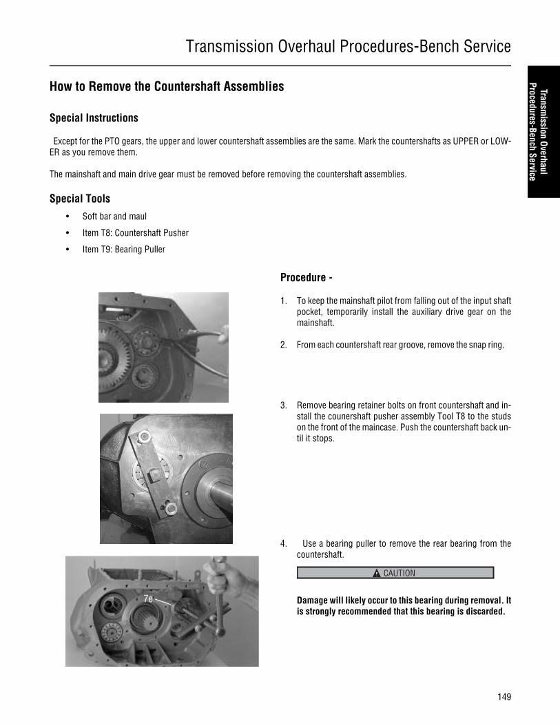
Transmission Overhaul Procedures-Bench Service
149
Transmission Overhaul
Procedures-Bench Service
How to Remove the Countershaft Assemblies
Special Instructions
Except for the PTO gears, the upper and lower countershaft assemblies are the same. Mark the countershafts as UPPER or LOW-ER as you remove them.
The mainshaft and main drive gear must be removed before removing the countershaft assemblies.
Special Tools
• Soft bar and maul
• Item T8: Countershaft Pusher
• Item T9: Bearing Puller
Procedure -
1. To keep the mainshaft pilot from falling out of the input shaftpocket, temporarily install the auxiliary drive gear on themainshaft.
2. From each countershaft rear groove, remove the snap ring.
3. Remove bearing retainer bolts on front countershaft and in-stall the counershaft pusher assembly Tool T8 to the studson the front of the maincase. Push the countershaft back un-til it stops.
4. Use a bearing puller to remove the rear bearing from thecountershaft.
Damage will likely occur to this bearing during removal. Itis strongly recommended that this bearing is discarded.
CAUTION

Transmission Overhaul Procedures-Bench Service
150
5. Remove tool T8 from the front countershaft.
6. Return to the case rear, and drive each countershaft forwardas far as possible. This exposes the external snap ring.
7. Use the appropriate bearing puller T9 to remove the counter-shaft front bearings.
8. Move the upper countershaft to the rear until the front bear-ing journal clears the front case bore.
9. Swing the front of the countershaft to the center of the case,and lift out the countershaft assembly.
Note: A large hook or piece of rope may help support thecountershaft.
Note: Follow the same procedure for lower countershaft re-moval.

Transmission Overhaul Procedures-Bench Service
151
Transmission Overhaul
Procedures-Bench Service
How to Disassemble the Countershaft Assemblies
Special Instructions
As you disassemble the countershafts, mark each part as belonging to the upper or lower countershafts, making sure the shaftposition is marked correctly. Due to available options, some shafts may be position specific.
Special Tools
• Press
1. Snap Ring2. Oil Pump Drive Gear3. Rear Bearing4. Countershaft5. Key6. Second Gear
7. Third Gear8. Overdrive/or 4th Gear9. PTO Gear10. Drive Gear11. Snap Ring12. Front Bearing
1
2
3
4
5
6
7
891011
12

Transmission Overhaul Procedures-Bench Service
152
Procedure -
1. Remove the snap ring from the front of the countershaft.
Never use the PTO gear as a pressing base. Due to its nar-row width, it may break.
2. Place the countershaft assembly in a press as shown. Withthe rear face of 4th or Overdrive gear from the front as abase, press this gear, the drive gear, and the PTO gear fromthe countershaft.
3. Reposition the countershaft in the press as shown. Usingthe rear face of 2nd speed gear as a base, press 3rd speedgear and 2nd speed gear from each countershaft.
4. Inspect the key. Remove and replace it if it is damaged.
CAUTION
1
2
3
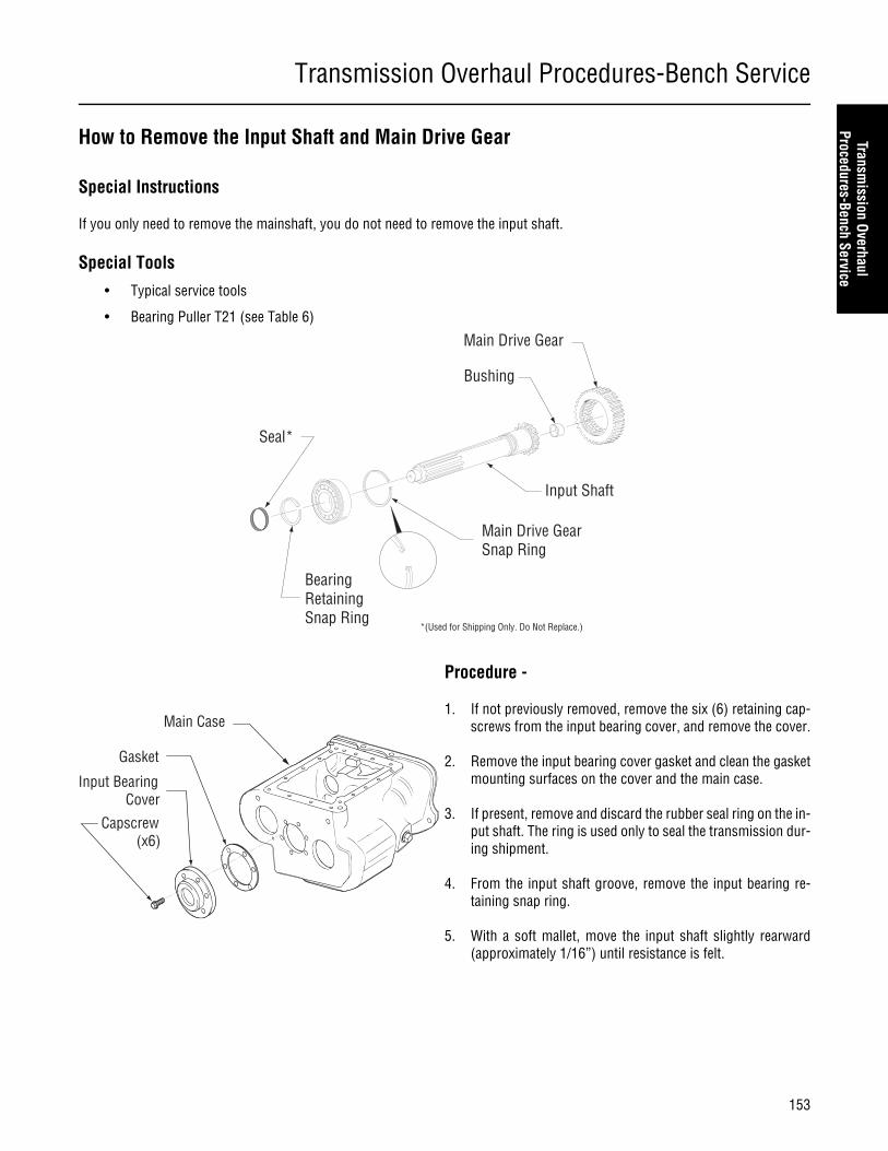
Transmission Overhaul Procedures-Bench Service
153
Transmission Overhaul
Procedures-Bench Service
How to Remove the Input Shaft and Main Drive Gear
Special Instructions
If you only need to remove the mainshaft, you do not need to remove the input shaft.
Special Tools
• Typical service tools
• Bearing Puller T21 (see Table 6)
Procedure -
1. If not previously removed, remove the six (6) retaining cap-screws from the input bearing cover, and remove the cover.
2. Remove the input bearing cover gasket and clean the gasketmounting surfaces on the cover and the main case.
3. If present, remove and discard the rubber seal ring on the in-put shaft. The ring is used only to seal the transmission dur-ing shipment.
4. From the input shaft groove, remove the input bearing re-taining snap ring.
5. With a soft mallet, move the input shaft slightly rearward(approximately 1/16”) until resistance is felt.
Main Drive Gear
Bushing
Input Shaft
Main Drive GearSnap Ring
BearingRetainingSnap Ring
Seal*
*(Used for Shipping Only. Do Not Replace.)
Capscrew(x6)
Input BearingCover
Gasket
Main Case

Transmission Overhaul Procedures-Bench Service
154
6. Grasp the input shaft and wiggle it. Pull it forward to movethe input bearing forward to expose the snap ring on the out-side of the input bearing.
Note: The input shaft can be removed from the front of thecase. Removal of the mainshaft is not required.
7. Install the bearing puller tool (Tool ref. ID T21) as shown andremove the input bearing from the case and input shaft.
8. Remove the snap ring on the inside of the main drive gear.
9. Pull the input shaft forward and out of the main drive gear.
10. From inside the case, remove the main drive gear.
6
7
8
10
9

Transmission Overhaul Procedures-Bench Service
155
Transmission Overhaul
Procedures-Bench Service
How to Prepare the Main Case for Reassembly
Verify that the three magnetic discs are firmly attached to the bottom of the main case. If they are not firmly attached, apply 3Mscotch grip or equivalent adhesive to the bottom of the discs and attach them to the main case.
If necessary, replace any damaged or worn clutch housing or rear support studs. Apply Eaton®Fuller® thread sealant #71205 orequivalent to any replacement studs before installing them.
Confirm that the rear support stud or capscrew does not protrude past the case housing into the transmission. If it protrudes,it could contact the range yoke and disrupt shifting between low and high range.
CAUTION
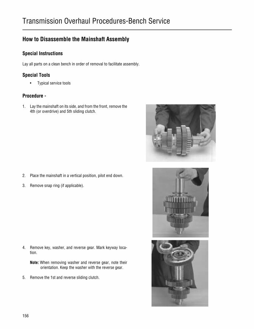
Transmission Overhaul Procedures-Bench Service
156
How to Disassemble the Mainshaft Assembly
Special Instructions
Lay all parts on a clean bench in order of removal to facilitate assembly.
Special Tools
• Typical service tools
Procedure -
1. Lay the mainshaft on its side, and from the front, remove the4th (or overdrive) and 5th sliding clutch.
2. Place the mainshaft in a vertical position, pilot end down.
3. Remove snap ring (if applicable).
4. Remove key, washer, and reverse gear. Mark keyway loca-tion.
Note: When removing washer and reverse gear, note theirorientation. Keep the washer with the reverse gear.
5. Remove the 1st and reverse sliding clutch.

Transmission Overhaul Procedures-Bench Service
157
Transmission Overhaul
Procedures-Bench Service
6. Remove the washer and 1st gear.
7. Remove the washer and 2nd gear.
8. Remove the washer and sliding clutch.
9. Remove the washer and 3rd gear.
10. Remove the washer.
11. Remove the 4th or overdrive gear.
12. Remove the washer.
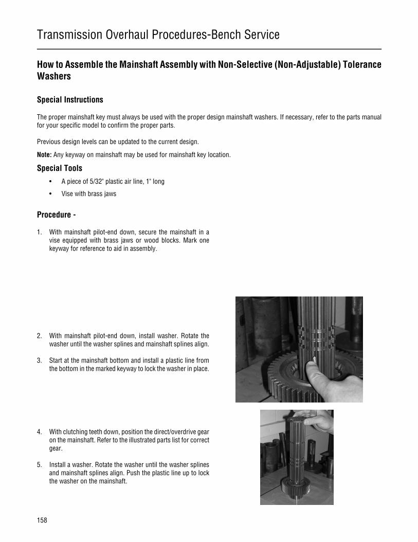
Transmission Overhaul Procedures-Bench Service
158
How to Assemble the Mainshaft Assembly with Non-Selective (Non-Adjustable) ToleranceWashers
Special Instructions
The proper mainshaft key must always be used with the proper design mainshaft washers. If necessary, refer to the parts manualfor your specific model to confirm the proper parts.
Previous design levels can be updated to the current design.
Note: Any keyway on mainshaft may be used for mainshaft key location.
Special Tools
• A piece of 5/32" plastic air line, 1" long
• Vise with brass jaws
Procedure -
1. With mainshaft pilot-end down, secure the mainshaft in avise equipped with brass jaws or wood blocks. Mark onekeyway for reference to aid in assembly.
2. With mainshaft pilot-end down, install washer. Rotate thewasher until the washer splines and mainshaft spIines align.
3. Start at the mainshaft bottom and install a plastic line fromthe bottom in the marked keyway to lock the washer in place.
4. With clutching teeth down, position the direct/overdrive gearon the mainshaft. Refer to the illustrated parts list for correctgear.
5. Install a washer. Rotate the washer until the washer splinesand mainshaft splines align. Push the plastic line up to lockthe washer on the mainshaft.
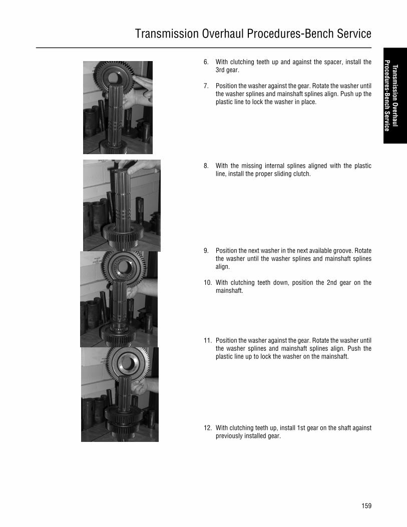
Transmission Overhaul Procedures-Bench Service
159
Transmission Overhaul
Procedures-Bench Service
6. With clutching teeth up and against the spacer, install the3rd gear.
7. Position the washer against the gear. Rotate the washer untilthe washer splines and mainshaft splines align. Push up theplastic line to lock the washer in place.
8. With the missing internal splines aligned with the plasticline, install the proper sliding clutch.
9. Position the next washer in the next available groove. Rotatethe washer until the washer splines and mainshaft splinesalign.
10. With clutching teeth down, position the 2nd gear on themainshaft.
11. Position the washer against the gear. Rotate the washer untilthe washer splines and mainshaft splines align. Push theplastic line up to lock the washer on the mainshaft.
12. With clutching teeth up, install 1st gear on the shaft againstpreviously installed gear.
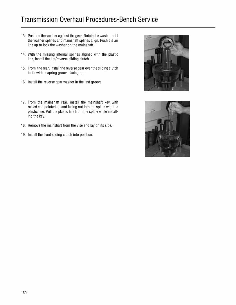
Transmission Overhaul Procedures-Bench Service
160
13. Position the washer against the gear. Rotate the washer untilthe washer splines and mainshaft splines align. Push the airline up to lock the washer on the mainshaft.
14. With the missing internal splines aligned with the plasticline, install the 1st/reverse sliding clutch.
15. From the rear, install the reverse gear over the sliding clutchteeth with snapring groove facing up.
16. Install the reverse gear washer in the last groove.
17. From the mainshaft rear, install the mainshaft key withraised end pointed up and facing out into the spline with theplastic line. Pull the plastic line from the spline while install-ing the key.
18. Remove the mainshaft from the vise and lay on its side.
19. Install the front sliding clutch into position.
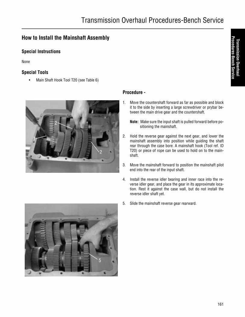
Transmission Overhaul Procedures-Bench Service
161
Transmission Overhaul
Procedures-Bench Service
How to Install the Mainshaft Assembly
Special Instructions
None
Special Tools
• Main Shaft Hook Tool T20 (see Table 6)
Procedure -
1. Move the countershaft forward as far as possible and blockit to the side by inserting a large screwdriver or prybar be-tween the main drive gear and the countershaft.
Note: Make sure the input shaft is pulled forward before po-sitioning the mainshaft.
2. Hold the reverse gear against the next gear, and lower themainshaft assembly into position while guiding the shaftrear through the case bore. A mainshaft hook (Tool ref. IDT20) or piece of rope can be used to hold on to the main-shaft.
3. Move the mainshaft forward to position the mainshaft pilotend into the rear of the input shaft.
4. Install the reverse idler bearing and inner race into the re-verse idler gear, and place the gear in its approximate loca-tion. Rest it against the case wall, but do not install thereverse idler shaft yet.
5. Slide the mainshaft reverse gear rearward.
1
2
2
5
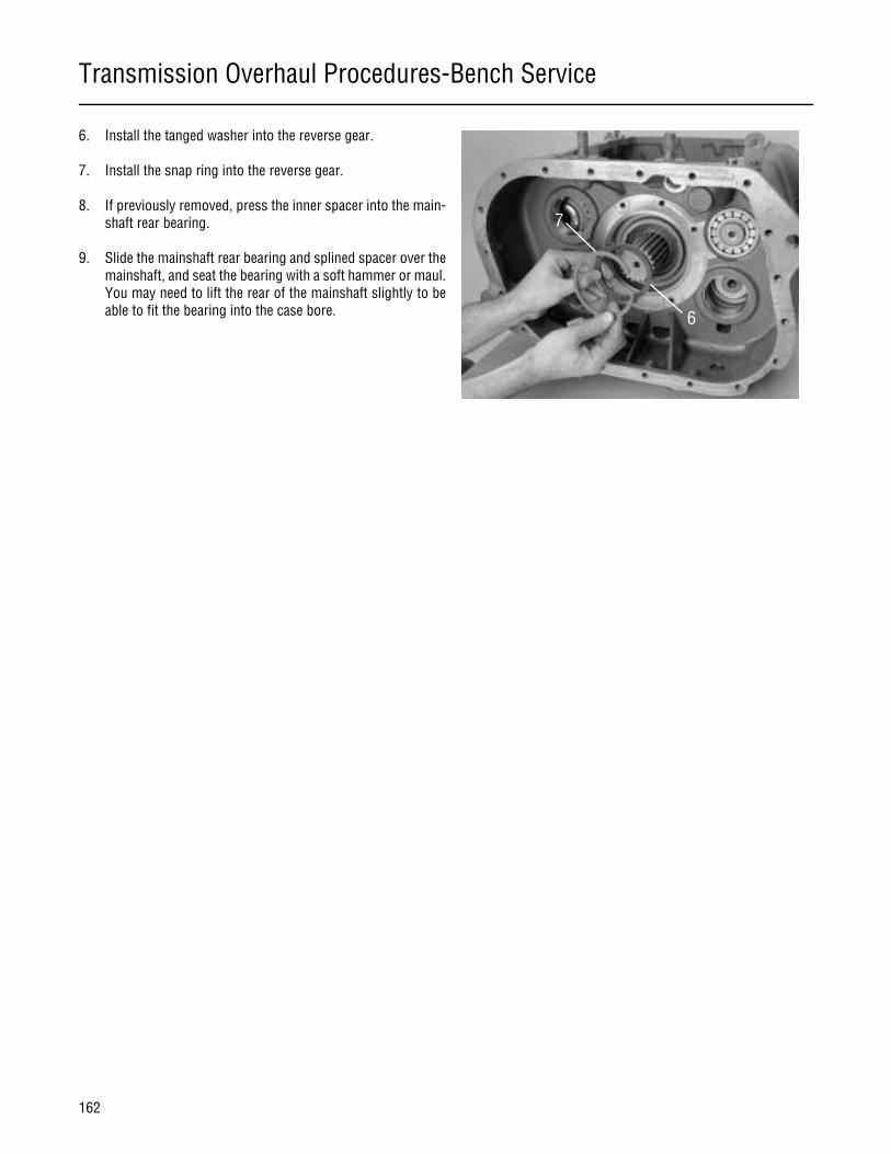
Transmission Overhaul Procedures-Bench Service
162
6. Install the tanged washer into the reverse gear.
7. Install the snap ring into the reverse gear.
8. If previously removed, press the inner spacer into the main-shaft rear bearing.
9. Slide the mainshaft rear bearing and splined spacer over themainshaft, and seat the bearing with a soft hammer or maul.You may need to lift the rear of the mainshaft slightly to beable to fit the bearing into the case bore. 6
7
Transmission Overhaul Procedures-Bench Service
163
Transmission Overhaul
Procedures-Bench Service
How to Assemble the Countershaft Assemblies
Special Instructions
Determine if the countershaft is the upper or lower countershaft, and mark it if necessary. The lower countershaft has a larger 47tooth PTO gear, and if the transmission has an oil pump, the rear of the shaft will be extended to support the oil pump drive gear.
Special Tools
• Press
Procedure -
1. If previously removed, install the key in the countershaftkeyway.
2. To ease assembly, lightly lubricate the shaft and inside di-ameter of each gear.
Note: Refer to the countershaft cross section while reas-sembling the countershaft and gears. If assembledcorrectly, the countershaft will have the same shapeas that shown in the cross section.
3. Install the 2nd speed gear (smallest gear). To install it, alignthe gear keyway with the countershaft key as shown, andpress the gear on the countershaft as shown.
4. Install the 3rd speed gear (next smallest gear). To install it,align the gear keyway with the countershaft key, and pressthe gear on the countershaft.
Overdrive ModelConfiguration
3
Transmission Overhaul Procedures-Bench Service
164
5. Perform one of the two following steps:
a. For overdrive transmissions, select the largest diametergear, place it over the shaft, and press it into place.
b. For direct drive transmissions, Install the 4th speedgear (next smallest gear). To install it, align the gearkeyway with the countershaft key, long hub to counter-shaft front, and press the gear on the countershaft.
6. Install the PTO gear. This gear is identified by the roundedteeth on one side. To install the PTO gear, align the gear key-way with the countershaft key, rounded teeth facing up(shaft rear), and press the gear on the countershaft.
7. Install the countershaft drive gear. This gear is identified bythe tooth marked with an “0.” To install the drive gear, alignthe gear keyway with the countershaft key, “0” to the front,and press the gear on the countershaft.
DO NOT try to install the countershaft in the transmissionif you cannot install the snap ring.
8. Install the countershaft drive gear retaining snap ring in thegroove on the shaft front. If the snap ring groove is not fullyexposed, either the gears are not oriented properly or notseated properly. The countershaft may have to be disassem-bled partly or fully to correct the problem.
9. For timing purposes, use a highly visible toolmakers die tomark the tooth with an “0” or the tooth lined up with the key-way.
CAUTION
8
9
Transmission Overhaul Procedures-Bench Service
165
Transmission Overhaul
Procedures-Bench Service
How to Assemble the Lower Reverse Idler Gear Assembly
Special Instructions
The new reverse idler shaft uses a snap ring in place of the capscrew.
Special Tools
• Torque Wrench 100 lb. ft. capacity
Procedure -
1. Position the reverse idler bearing and inner race into the re-verse idler gear.
2. Hold the reverse idler gear and flat thrust washer in place inthe main case, and insert the idler shaft, threaded end to thefront, through the rear case bore and into the gear. Do notinsert the reverse idler shaft into the main case support bossyet.
3. Position the slotted thrust washer in front of the gear with aslot facing up. Note the word FRONT on the slotted washer,and make sure it faces the front of the transmission. Contin-ue to feed the idler shaft forward through this washer andinto the hole in the case boss.
4. Slide the reverse idler shaft into the support boss bore, andwith a soft bar and driver, drive the reverse idler shaft fullyinto position.
5. Secure the shaft in position according to one of the proce-dures below:
Previous Design
Slotted Thrust Washer
InnerRace
Notched ThrustWasher
BearingReverseIdler Gear
Reverse IdlerShaft
Snap Ring
CapscrewWasher
Current Design
Slotted Thrust Washer
InnerRace
Notched ThrustWasher
BearingReverseIdler Gear
Reverse IdlerShaft
Snap Ring
Snap RingWasher
5

Transmission Overhaul Procedures-Bench Service
166
Note: For Nut Fastener Design: Inspect the nylon locking in-sert in the nut, and replace the nut if it is excessivelyworn. After inspecting and/or replacing the nut, installthe nut and washer on shaft front. Tighten the nut to67-75 lb. ft. (90 to 101 N•m) of torque.
Note: For Capscrew Fastener Design: Apply Eaton®Fuller®thread sealant #71205 or equivalent to the capscrewthreads, and install the capscrew and washer. Tightenthe capscrew to 67-75 lb. ft. (90 to 101 N•m) oftorque.
Note: For Snap-ring design: Install the washer and snap ringon idler shaft using socket. Place snap-ring over frontof reverse idler shaft seal, snapping into place by us-ing a large socket. Tap lightly into place.
Transmission Overhaul Procedures-Bench Service
167
Transmission Overhaul
Procedures-Bench Service
How to Install Countershaft Assemblies
Special Instructions
Make sure the countershaft assemblies have been marked for proper position, 47- tooth PTO gear in the lower position.
Prior to installing the countershafts, the lower reverse idler gear assembly should be installed. In addition, if the transmission isequipped with an internal oil pump, this should also be installed.
Special Tools
• Toolmaker’s dye
Procedure -
1. On the drive gear of each countershaft assembly, mark thetooth aligned with the gear keyway and stamped with an "O"for easy identification. A highly visible color of toolmaker’sdye is recommended for making timing marks.
Note: Prior to installing the countershafts, the lower reverseidler gear assembly should be installed. In addition, ifthe transmission is equipped with an internal oilpump, this should also be installed.
2. Place the lower, 47-tooth PTO gear countershaft, into themain case with the shaft seated in the lower countershaftcase bores.
Note: Use a large hook or piece of rope to support the coun-tershaft if necessary.
3. Place the upper countershaft (with the 45 tooth PTO gear)into the main case with the shaft seated in the upper coun-tershaft case bores.
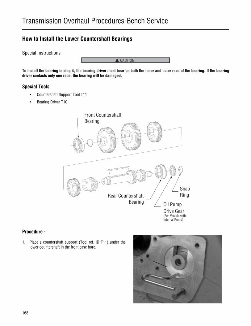
Transmission Overhaul Procedures-Bench Service
168
How to Install the Lower Countershaft Bearings
Special Instructions
To install the bearing in step 4, the bearing driver must bear on both the inner and outer race of the bearing. If the bearingdriver contacts only one race, the bearing will be damaged.
Special Tools
• Countershaft Support Tool T11
• Bearing Driver T10
Procedure -
1. Place a countershaft support (Tool ref. ID T11) under thelower countershaft in the front case bore.
CAUTION
Front CountershaftBearing
Rear CountershaftBearing Oil Pump
Drive Gear(For Models with Internal Pump)
SnapRing
1
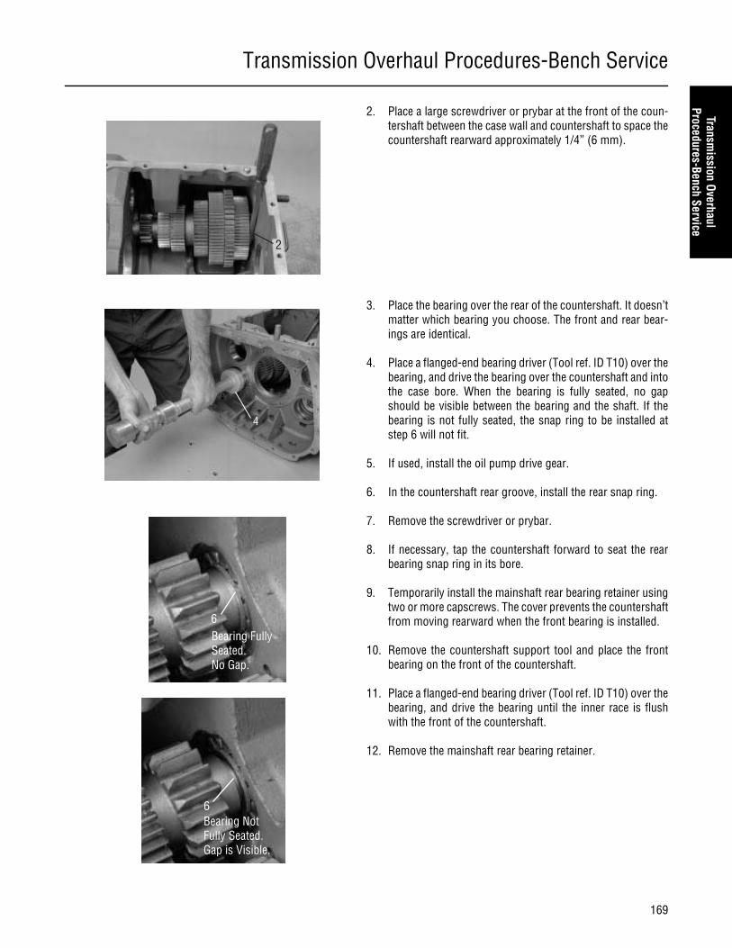
Transmission Overhaul Procedures-Bench Service
169
Transmission Overhaul
Procedures-Bench Service
2. Place a large screwdriver or prybar at the front of the coun-tershaft between the case wall and countershaft to space thecountershaft rearward approximately 1/4” (6 mm).
3. Place the bearing over the rear of the countershaft. It doesn’tmatter which bearing you choose. The front and rear bear-ings are identical.
4. Place a flanged-end bearing driver (Tool ref. ID T10) over thebearing, and drive the bearing over the countershaft and intothe case bore. When the bearing is fully seated, no gapshould be visible between the bearing and the shaft. If thebearing is not fully seated, the snap ring to be installed atstep 6 will not fit.
5. If used, install the oil pump drive gear.
6. In the countershaft rear groove, install the rear snap ring.
7. Remove the screwdriver or prybar.
8. If necessary, tap the countershaft forward to seat the rearbearing snap ring in its bore.
9. Temporarily install the mainshaft rear bearing retainer usingtwo or more capscrews. The cover prevents the countershaftfrom moving rearward when the front bearing is installed.
10. Remove the countershaft support tool and place the frontbearing on the front of the countershaft.
11. Place a flanged-end bearing driver (Tool ref. ID T10) over thebearing, and drive the bearing until the inner race is flushwith the front of the countershaft.
12. Remove the mainshaft rear bearing retainer.
2
4
6Bearing FullySeated.No Gap.
6Bearing NotFully Seated.Gap is Visible.

Transmission Overhaul Procedures-Bench Service
170
How to Install the Input Shaft and Main Drive Gear
Special Instructions
None
Special Tools
• Bearing Driver T12 (see Table 6
• Toolmaker’s Die
Procedure -
1. Use a highly visible toolmaker’s dye and mark the main drivegear for timing purposes. To mark the gear, paint the tool-maker’s die on any two adjacent teeth, and then paint thetwo adjacent teeth directly opposite the first two teeth.
2. If necessary, install the bushing in the back of the inputshaft.
3. From inside the case, position and hold the main drive gearin its approximate position.
Main Drive Gear
Bushing
Input Shaft
Main Drive GearSnap Ring
BearingRetainingSnap Ring
Seal*
*(Used for Shipping Only. Do Not Replace.)
1
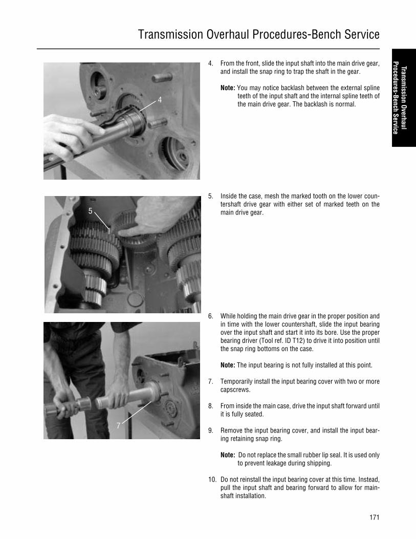
Transmission Overhaul Procedures-Bench Service
171
Transmission Overhaul
Procedures-Bench Service
4. From the front, slide the input shaft into the main drive gear,and install the snap ring to trap the shaft in the gear.
Note: You may notice backlash between the external splineteeth of the input shaft and the internal spline teeth ofthe main drive gear. The backlash is normal.
5. Inside the case, mesh the marked tooth on the lower coun-tershaft drive gear with either set of marked teeth on themain drive gear.
6. While holding the main drive gear in the proper position andin time with the lower countershaft, slide the input bearingover the input shaft and start it into its bore. Use the properbearing driver (Tool ref. ID T12) to drive it into position untilthe snap ring bottoms on the case.
Note: The input bearing is not fully installed at this point.
7. Temporarily install the input bearing cover with two or morecapscrews.
8. From inside the main case, drive the input shaft forward untilit is fully seated.
9. Remove the input bearing cover, and install the input bear-ing retaining snap ring.
Note: Do not replace the small rubber lip seal. It is used onlyto prevent leakage during shipping.
10. Do not reinstall the input bearing cover at this time. Instead,pull the input shaft and bearing forward to allow for main-shaft installation.
4
5
7
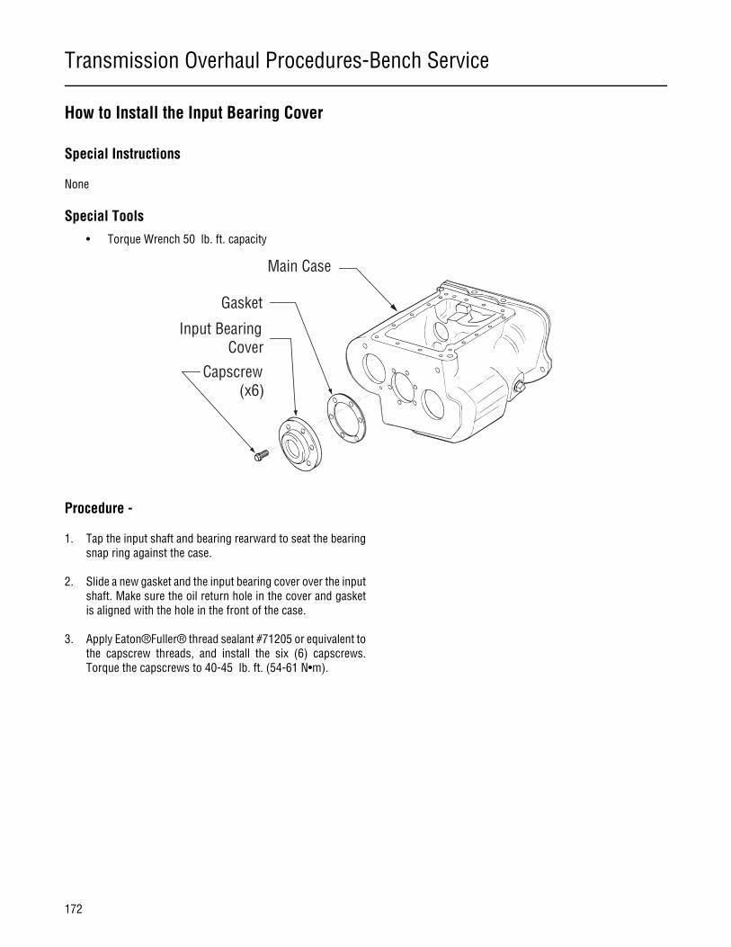
Transmission Overhaul Procedures-Bench Service
172
How to Install the Input Bearing Cover
Special Instructions
None
Special Tools
• Torque Wrench 50 lb. ft. capacity
Procedure -
1. Tap the input shaft and bearing rearward to seat the bearingsnap ring against the case.
2. Slide a new gasket and the input bearing cover over the inputshaft. Make sure the oil return hole in the cover and gasketis aligned with the hole in the front of the case.
3. Apply Eaton®Fuller® thread sealant #71205 or equivalent tothe capscrew threads, and install the six (6) capscrews.Torque the capscrews to 40-45 lb. ft. (54-61 N•m).
Capscrew(x6)
Input BearingCover
Gasket
Main Case

Transmission Overhaul Procedures-Bench Service
173
Transmission Overhaul
Procedures-Bench Service
How to Install the Upper Countershaft Bearings
Special Instructions
None
Special Tools
• Countershaft Support Tool T11
• Bearing Driver T10
Procedure -
1. Make sure the lower countershaft and main drive gear timingmarks are aligned.
2. Mesh the marked tooth of the upper countershaft with thetwo remaining marked teeth of the main drive gear.
3. Support and center the front of the countershaft by placinga support tool (Tool ref. ID T11) in the front bore as shown.
4. Place a large screwdriver or prybar at the front of the coun-tershaft between the case wall and countershaft to space thecountershaft rearward approximately 1/4” (6 mm).
5. Place a bearing over the rear of the countershaft. It doesn’tmatter which bearing is chosen. The front and rear bearingsare identical.
The bearing driver must bear on both the inner and outerrace of the bearing. If the bearing driver contacts only onerace, the bearing will be damaged.
3
4
CAUTION

Transmission Overhaul Procedures-Bench Service
174
6. Place a flanged-end bearing driver (Tool ref. ID T10) over thecountershaft rear bearing, and drive the bearing into thecase bore. The countershaft may need to be lifted slightly tostart the bearing into the bore. When the bearing is fullyseated, no gap should be visible between the bearing and theshaft. If the bearing is not fully seated, the snap ring to beinstalled at step 7 will not fit.
7. In the countershaft rear groove, install the rear snap ring.
8. Remove the screwdriver or prybar.
9. If necessary, tap the countershaft forward to seat the rearbearing in its bore.
10. Install the mainshaft rear bearing retainer. To install thebearing retainer, apply Eaton®Fuller® thread sealant#71205 or equivalent to the capscrews, and install them inthe bearing retainer. Torque the screws to 40-45 lb-ft (54-61N•m)
11. Remove the timing block and place the remaining bearing onthe front of the countershaft.
12. Place a flanged-end bearing driver (Tool ref. ID T10) over thebearing, and drive the bearing over the countershaft until theinner race is flush with the end of the countershaft.
6Bearing FullySeated.No Gap.
6Bearing NotFully Seated.Gap is Visible.
10
12
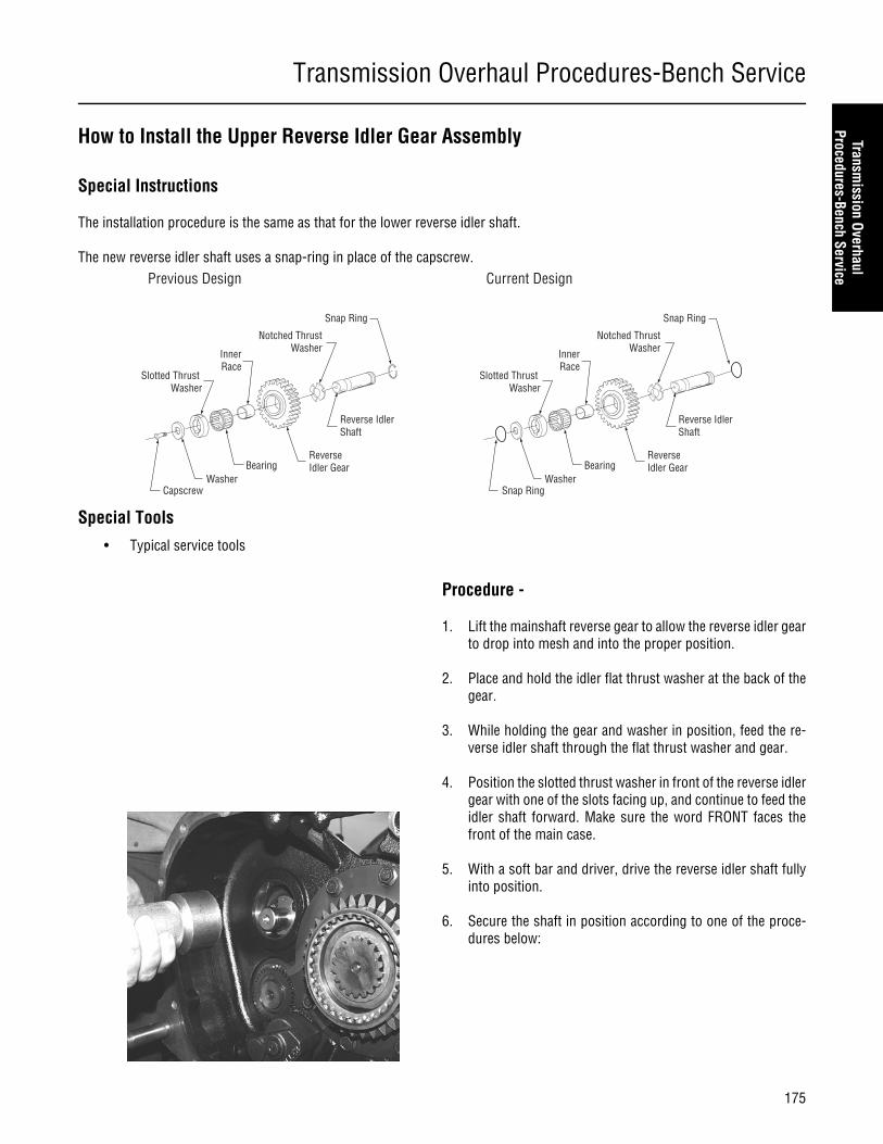
Transmission Overhaul Procedures-Bench Service
175
Transmission Overhaul
Procedures-Bench Service
How to Install the Upper Reverse Idler Gear Assembly
Special Instructions
The installation procedure is the same as that for the lower reverse idler shaft.
The new reverse idler shaft uses a snap-ring in place of the capscrew.
Special Tools
• Typical service tools
Procedure -
1. Lift the mainshaft reverse gear to allow the reverse idler gearto drop into mesh and into the proper position.
2. Place and hold the idler flat thrust washer at the back of thegear.
3. While holding the gear and washer in position, feed the re-verse idler shaft through the flat thrust washer and gear.
4. Position the slotted thrust washer in front of the reverse idlergear with one of the slots facing up, and continue to feed theidler shaft forward. Make sure the word FRONT faces thefront of the main case.
5. With a soft bar and driver, drive the reverse idler shaft fullyinto position.
6. Secure the shaft in position according to one of the proce-dures below:
Previous Design
Slotted Thrust Washer
InnerRace
Notched ThrustWasher
BearingReverseIdler Gear
Reverse IdlerShaft
Snap Ring
CapscrewWasher
Current Design
Slotted Thrust Washer
InnerRace
Notched ThrustWasher
BearingReverseIdler Gear
Reverse IdlerShaft
Snap Ring
Snap RingWasher
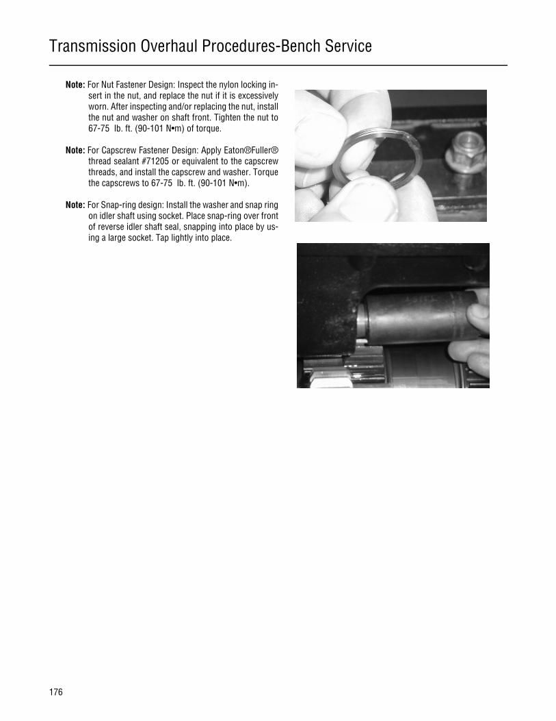
Transmission Overhaul Procedures-Bench Service
176
Note: For Nut Fastener Design: Inspect the nylon locking in-sert in the nut, and replace the nut if it is excessivelyworn. After inspecting and/or replacing the nut, installthe nut and washer on shaft front. Tighten the nut to67-75 lb. ft. (90-101 N•m) of torque.
Note: For Capscrew Fastener Design: Apply Eaton®Fuller®thread sealant #71205 or equivalent to the capscrewthreads, and install the capscrew and washer. Torquethe capscrews to 67-75 lb. ft. (90-101 N•m).
Note: For Snap-ring design: Install the washer and snap ringon idler shaft using socket. Place snap-ring over frontof reverse idler shaft seal, snapping into place by us-ing a large socket. Tap lightly into place.
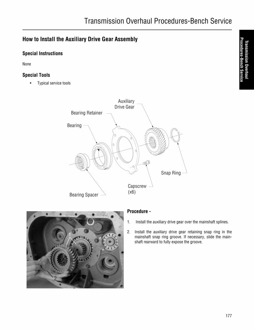
Transmission Overhaul Procedures-Bench Service
177
Transmission Overhaul
Procedures-Bench Service
How to Install the Auxiliary Drive Gear Assembly
Special Instructions
None
Special Tools
• Typical service tools
Procedure -
1. Install the auxiliary drive gear over the mainshaft splines.
2. Install the auxiliary drive gear retaining snap ring in themainshaft snap ring groove. If necessary, slide the main-shaft rearward to fully expose the groove.
Bearing Spacer
Bearing
Bearing Retainer
Capscrew(x6)
AuxiliaryDrive Gear
Snap Ring
1
2

Transmission Overhaul Procedures-Bench Service
178
How to Install the Clutch Housing
Special Instructions
The procedure is the same for aluminum or cast iron housings.
If you replace the clutch housing, DO NOT replace it with one machined before January 1, 1995. It will not have the propercountershaft bearing relief machined into the countershaft bearing pockets and could cause interference between the coun-tershaft bearings and clutch housing.
Special Tools
• Typical service tools
Procedure -
1. Position a new gasket on the housing mounting surface.
Note: The input bearing cover must be installed before youinstall the clutch housing.
2. Install the clutch housing on the six (6) studs on the maincase, piloting it on the front input bearing cover.
Note: Cast iron clutch housings use split-type lockwashers.Aluminum clutch housings use a flat washer with thenut and star-type lockwashers with the capscrews.
3. Install the nuts with washers or lockwashers on the studs,tighten to 180-200 lb. ft. (244-271 N•m) of torque.
4. Apply Eaton®Fuller® thread sealant #71205 to the cap-screws and install them with lockwashers. Tighten the cap-screws to 72-80 lb. ft. (97-108 N•m) of torque.
CAUTION
Main Case
Gasket
ClutchHousing
Cap Screw(x4)
Washer (x6)
Nut (x6)
Stud

Transmission Overhaul Procedures-Bench Service
179
Transmission Overhaul
Procedures-Bench Service
Note: The torque value is the same for aluminum or cast ironhousings.

Transmission Overhaul Procedures-Bench Service
180
How to Remove the Oil Pump
Special Instructions
None
Special Tools
• Typical service tools
Procedure -
1. Use a 6 mm allen socket driver to remove the single sockethead shoulder bolt.
2. Remove the oil pump.
3. If necessary, remove the pump drive gear by removing thecountershaft rear snap ring.1
2

Transmission Overhaul Procedures-Bench Service
181
Transmission Overhaul
Procedures-Bench Service
How to Install the Oil Pump
Special Instructions
Overtightening the attaching bolt could bind up the pump.
Special Tools
• Torque Wrench 25 lb. ft. capacity
Procedure -
1. From the rear of the transmission, position the oil pump intoplace.
2. Install the socket head shoulder bolt to secure the pump inplace.
Overtightening the bolt could bind up the pump.
3. With a 6 mm socket head driver, torque the bolt to 20-23 lb.ft. (27-31 N•m). 2
1
2
3
CAUTION
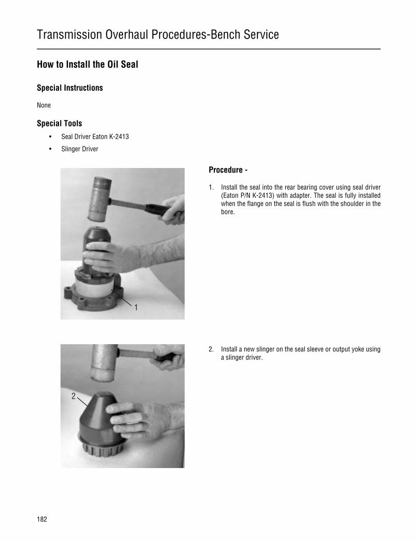
Transmission Overhaul Procedures-Bench Service
182
How to Install the Oil Seal
Special Instructions
None
Special Tools
• Seal Driver Eaton K-2413
• Slinger Driver
Procedure -
1. Install the seal into the rear bearing cover using seal driver(Eaton P/N K-2413) with adapter. The seal is fully installedwhen the flange on the seal is flush with the shoulder in thebore.
2. Install a new slinger on the seal sleeve or output yoke usinga slinger driver.
1
2
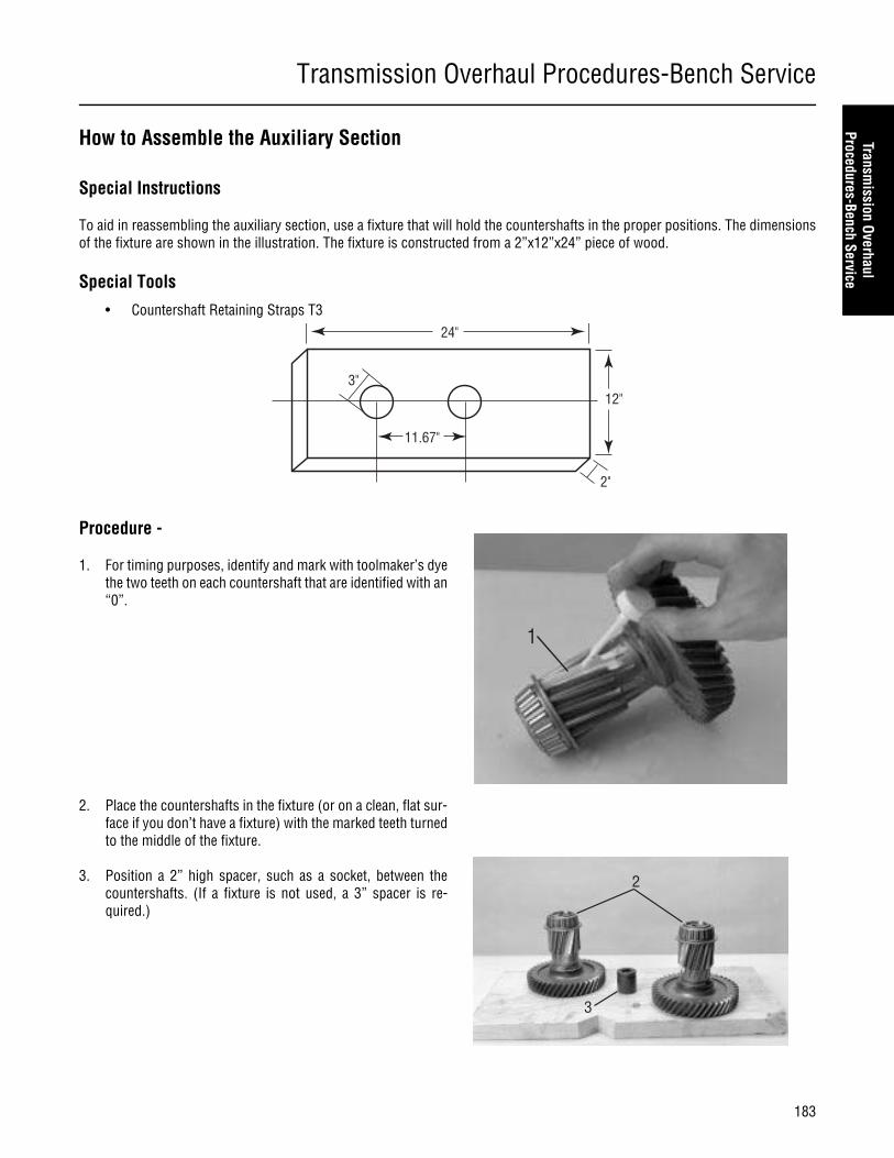
Transmission Overhaul Procedures-Bench Service
183
Transmission Overhaul
Procedures-Bench Service
How to Assemble the Auxiliary Section
Special Instructions
To aid in reassembling the auxiliary section, use a fixture that will hold the countershafts in the proper positions. The dimensionsof the fixture are shown in the illustration. The fixture is constructed from a 2”x12”x24” piece of wood.
Special Tools
• Countershaft Retaining Straps T3
Procedure -
1. For timing purposes, identify and mark with toolmaker’s dyethe two teeth on each countershaft that are identified with an“0”.
2. Place the countershafts in the fixture (or on a clean, flat sur-face if you don’t have a fixture) with the marked teeth turnedto the middle of the fixture.
3. Position a 2” high spacer, such as a socket, between thecountershafts. (If a fixture is not used, a 3” spacer is re-quired.)
24"
12"
2"
11.67"
3"
1
2
3
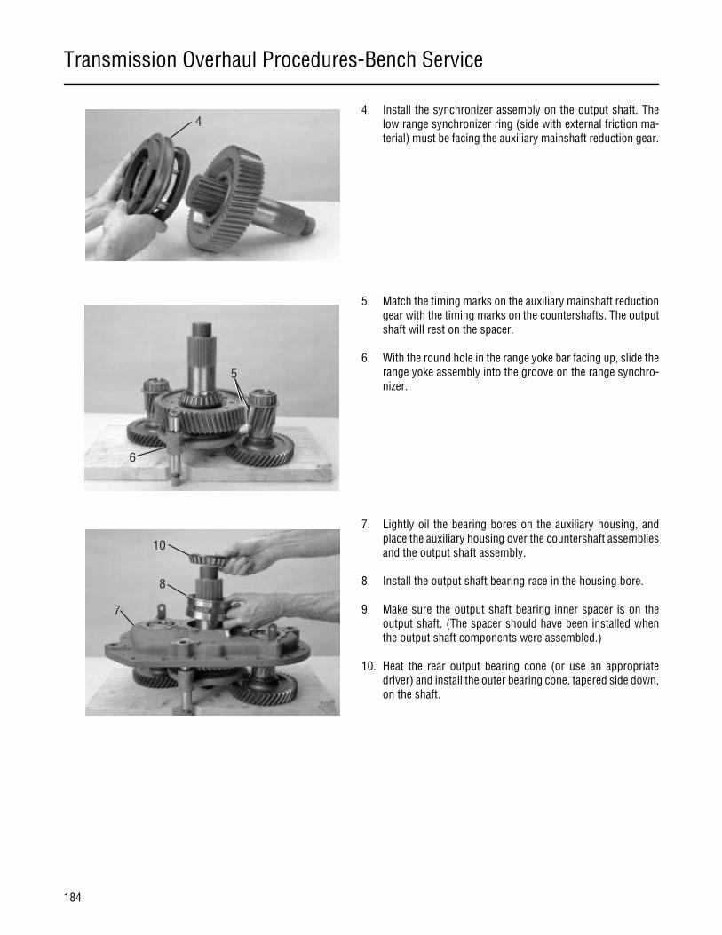
Transmission Overhaul Procedures-Bench Service
184
4. Install the synchronizer assembly on the output shaft. Thelow range synchronizer ring (side with external friction ma-terial) must be facing the auxiliary mainshaft reduction gear.
5. Match the timing marks on the auxiliary mainshaft reductiongear with the timing marks on the countershafts. The outputshaft will rest on the spacer.
6. With the round hole in the range yoke bar facing up, slide therange yoke assembly into the groove on the range synchro-nizer.
7. Lightly oil the bearing bores on the auxiliary housing, andplace the auxiliary housing over the countershaft assembliesand the output shaft assembly.
8. Install the output shaft bearing race in the housing bore.
9. Make sure the output shaft bearing inner spacer is on theoutput shaft. (The spacer should have been installed whenthe output shaft components were assembled.)
10. Heat the rear output bearing cone (or use an appropriatedriver) and install the outer bearing cone, tapered side down,on the shaft.
4
6
5
8
7
10
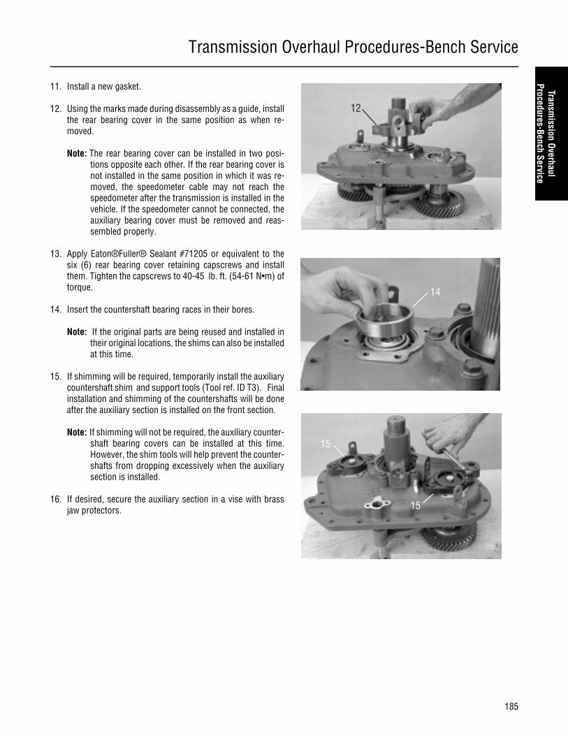
Transmission Overhaul Procedures-Bench Service
185
Transmission Overhaul
Procedures-Bench Service
11. Install a new gasket.
12. Using the marks made during disassembly as a guide, installthe rear bearing cover in the same position as when re-moved.
Note: The rear bearing cover can be installed in two posi-tions opposite each other. If the rear bearing cover isnot installed in the same position in which it was re-moved, the speedometer cable may not reach thespeedometer after the transmission is installed in thevehicle. If the speedometer cannot be connected, theauxiliary bearing cover must be removed and reas-sembled properly.
13. Apply Eaton®Fuller® Sealant #71205 or equivalent to thesix (6) rear bearing cover retaining capscrews and installthem. Tighten the capscrews to 40-45 lb. ft. (54-61 N•m) oftorque.
14. Insert the countershaft bearing races in their bores.
Note: If the original parts are being reused and installed intheir original locations, the shims can also be installedat this time.
15. If shimming will be required, temporarily install the auxiliarycountershaft shim and support tools (Tool ref. ID T3). Finalinstallation and shimming of the countershafts will be doneafter the auxiliary section is installed on the front section.
Note: If shimming will not be required, the auxiliary counter-shaft bearing covers can be installed at this time.However, the shim tools will help prevent the counter-shafts from dropping excessively when the auxiliarysection is installed.
16. If desired, secure the auxiliary section in a vise with brassjaw protectors.
12
14
15
15

Transmission Overhaul Procedures-Bench Service
186
17. On the auxiliary housing back, install the range alignmentlock cover and O-ring. Rotate the cover to the unlock posi-tion, and secure the cover in place with a capscrew.
New units don’t contain the lock cover, so the shift barhousing must remain off until the auxiliary section andrange cylinder are assembled.
18. Install the O-ring over the output shaft, and insert it againstthe output bearing.
19. Install the speedometer rotor/seal sleeve.
20. Install the output yoke over the output shaft. The yokeshould slide on and stop before contacting the speedometerrotor. As the output shaft nut is installed, the output yoke willcontact the speedometer rotor.
21. Inspect the output nut for damage and wear. If the nylonlocking material is damaged or excessively worn, use a newoutput nut.
Note: The nylon locking material must be in good conditionto prevent the nut from loosening during operation.
22. Lightly oil the output shaft threads and the output nutthreads and install the nut. Torque the nut to 450-500 lb. ft.(610-677 N•m).
17
CAUTION
18
19
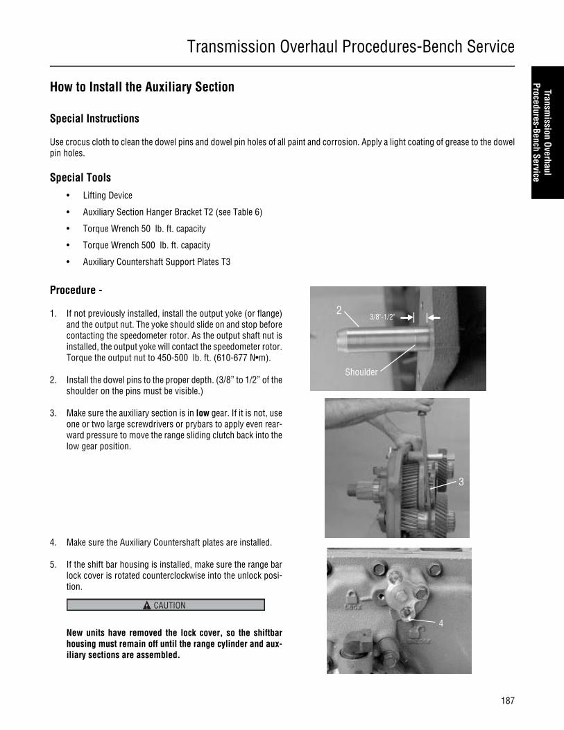
Transmission Overhaul Procedures-Bench Service
187
Transmission Overhaul
Procedures-Bench Service
How to Install the Auxiliary Section
Special Instructions
Use crocus cloth to clean the dowel pins and dowel pin holes of all paint and corrosion. Apply a light coating of grease to the dowelpin holes.
Special Tools
• Lifting Device
• Auxiliary Section Hanger Bracket T2 (see Table 6)
• Torque Wrench 50 lb. ft. capacity
• Torque Wrench 500 lb. ft. capacity
• Auxiliary Countershaft Support Plates T3
Procedure -
1. If not previously installed, install the output yoke (or flange)and the output nut. The yoke should slide on and stop beforecontacting the speedometer rotor. As the output shaft nut isinstalled, the output yoke will contact the speedometer rotor.Torque the output nut to 450-500 lb. ft. (610-677 N•m).
2. Install the dowel pins to the proper depth. (3/8” to 1/2” of theshoulder on the pins must be visible.)
3. Make sure the auxiliary section is in low gear. If it is not, useone or two large screwdrivers or prybars to apply even rear-ward pressure to move the range sliding clutch back into thelow gear position.
4. Make sure the Auxiliary Countershaft plates are installed.
5. If the shift bar housing is installed, make sure the range barlock cover is rotated counterclockwise into the unlock posi-tion.
New units have removed the lock cover, so the shiftbarhousing must remain off until the range cylinder and aux-iliary sections are assembled.
Shoulder
23/8"-1/2"
3
4
CAUTION

Transmission Overhaul Procedures-Bench Service
188
6. Position the gasket on the main case mounting surface.
7. Attach the auxiliary section hanger bracket to the top of theauxiliary section, and attach the chain of the lifting device tothe bracket. (Tool ref. ID T2)
8. Allow the lifting device to support the weight of the auxiliarysection, and position the auxiliary section on the two dowelpins. Slide the auxiliary section forward.
Note: The range yoke bar must slide into the bore in themain case.
Note: To help the auxiliary countershafts mesh with the aux-iliary drive gear, rotate the output yoke to turn thegearing.
Note: If the auxiliary countershafts drop excessively, theauxiliary countershaft shim tools (Tool ref. ID T3) canbe used to support the countershafts.
Note: The auxiliary section can be assembled to the trans-mission with the transmission in the vertical position.
9. Remove the auxiliary section hanger bracket.
Do not force or pull the auxiliary section into position withcapscrews when sliding it into place. It should slide intoplace fairly easily. If excessive force is necessary, thecountershafts are drooping or the gearing is not in propermesh, remove the auxiliary section and try again.
10. Slide the auxiliary section fully into position.
11. Apply Eaton®Fuller® thread sealant #71205 to the cap-screw threads, and install the 19 capscrews. Torque them to40-45 lb. ft. (54-61 N•m)
12. Remove the capscrew securing the range bar lock cover inthe unlock position and rotate the cover to the lock position.Insert the two capscrews to secure the lock cover in posi-tion. Torque them to 20-23 lb. ft. (27-31 N•m).
Note: To properly align the lock cover, the auxiliary sectionmust be in low range when the capscrews are tight-ened.
13. Remove the auxiliary countershaft rear bearing covers, andshim the countershafts using the procedure on the followingpage.
6
CAUTION

Transmission Overhaul Procedures-Bench Service
189
Transmission Overhaul
Procedures-Bench Service
Shim Procedure without a Shim Tool for Tapered Bearings
Special Instructions
The shim procedure can be done in the horizontal or vertical position. The procedure is done the same.
Use genuine Eaton® replacement gaskets for the auxiliary housing and countershaft bearing cover. Do not omit the gaskets.Bearing endplay is influenced by the compressed thickness of the gasket (.011-.012" or .28-.30 mm.
The bearing endplay must be checked and adjusted any time a countershaft, bearing, or housing is replaced. If, during reassembly,the same countershaft, bearings, housing, and shims are reused and kept in the same location, it is not necessary to reset bearingendplay.
The following procedure is used to adjust the endplay for the auxiliary countershaft tapered bearings. By correctly following thisprocedure, each countershaft will have .001"-.005" (.03-.12 mm) endplay.
Shims must be aligned properly or else the rear bearing cover may be damaged when final torque is applied.
Procedure -
1. The auxiliary countershaft bearing covers or countershaftstraps and shims should be removed. Make sure all old gas-ket material is cleaned from the gasket mounting surfaceson the countershaft bearing covers and the auxiliary hous-ing.
2. Verify that the auxiliary section is in gear. When the outputshaft is rotated, the countershafts must also rotate. If notshift the auxiliary into gear by applying shop air to the highrange air port on range cylinder to shift into gear.
3. Make sure a 0.100 countershaft rear bearing shim is in-stalled. Be sure the countershaft rear bearing races are seat-ed in the bearing bores.
4. Install two (2) clean 3/8 " x 1" capscrews without washers di-rectly across from each other in each bearing cover. Tappedholes in auxiliary case must be free of thread adhesive.
5. Evenly tighten the capscrews to 7 Lb·in of torque. Do not in-stall the countershaft rear bearing cover gasket. The gap be-tween the bearing cover and the housing surface should beeven from side to side.
Note: 7 Lb·in is slightly more than finger tight. Do not over-tighten the capscrews. If the capscrews are too tight,the bearing cover will become distorted.
CAUTION

Transmission Overhaul Procedures-Bench Service
190
6. Rotate the output shaft 4 times clockwise and 4 times coun-terclockwise. The rotation will seat and align the rollers ineach tapered bearing. Re-torque the capscrews to 7 Lb·in.If the countershafts do not rotate, the range sliding clutch ordeep reduction sliding clutch is in neutral. Apply shop com-pressed air to shift cylinders to shift the sliding clutches intogear.
7. Use a feeler gauge, as close to each capscrew location aspossible, and measure the gap between the countershaftrear bearing cover and the auxiliary housing gasket surface.Measure and record the gap at two capscrew locations.
8. Average the two feeler gauge measurements by adding themeasurements together and dividing by 2 as shown in Ex-ample.
9. Locate the feeler gauge average measurement in the shimchart to determine the required shim and color code.
Note: The oil pump shim is used when an auxiliary oil pumpor PTO is mounted on the countershaft. The oil pumpshims have a smaller outside diameter.
10. Remove the countershaft rear bearing cover and gaugingshim.
11. Place the selected shim on the rear countershaft bearingrace.
12. Position a new gasket on countershaft rear bearing covermounting surface.
13. Position the countershaft rear bearing cover over the newgasket.
14. Apply Eaton® Fuller® thread sealant #71205 or equivalentto the auxiliary countershaft rear bearing cover capscrewsand auxiliary countershaft rear bearing cover.
Shim Chart
Gap 1 = .060 ; Gap 2 = .050
Total Gap = .060 + .050 = .110
Average = 110/2 = .055
Select yellow shim as indicated in the shim chart at the end ofthis selection.
Transmission Overhaul Procedures-Bench Service
191
Transmission Overhaul
Procedures-Bench Service
15. Install the auxiliary countershaft rear bearing cover and se-cure it with the capscrews. Make sure the shim is in theproper location and is not pinched between the cover andthe housing. Tighten the capscrews to 40-45 Lb·ft (54-61Nm).
Note: Use a thick grease to hold the shim in position wheninstalling the cover.
16. Repeat this procedure for the remaining countershaft.
Note: Make sure capscrews are properly torqued.
Note: Make sure the input shaft rotates.
Shim Table
Feeler Gauge AverageGap
Shim Thickness Standard Shim PartNumber
Oil Pump Shim Part Num-ber
Color Code
.072-.075 .033-.034 4302345 4302346 Gold
.69-.0715 .036-.037 21452 21472 Red
.066-.0685 .039-.040 21453 21473 Pink
.063-.0655 .042-.043 21454 21474 Brown
.060-.0625 .045-.046 21455 21475 Tan
.057-.0595 .048-.049 21456 21476 Orange
.054-.0565 .051-.052 21457 21477 Yellow
.051-.0535 .054-.055 21458 21478 Green
.048-.0505 .057-.058 21459 21479 Light Blue
.045-.0475 .060-.061 21460 21480 Lavender
.042-.0445 .063-.064 21461 21481 White
.039-.0415 .066-.067 21684 21686 Black
.036-.0385 .069-.070 21685 21687 Silver
For spec’ing or service assistance, call 1-800-826-HELP (4357) 24 hours a day, 7 days a week (Mexico:001-800-826-4357), for more time on the road. Or visit our web site at www.roadranger.com.
Eaton Corporation • Truck Components Operations • P.O. Box 4013 • Kalamazoo, MI 49003 • U.S.A. • www.roadranger.com
Roadranger: Eaton, Dana and other trusted partners providing the best products and services in the industry, ensuring more time on the road.
©2008 Eaton Corporation · All rights reserved.Printed in USA
Copyright Eaton Corporation and Dana Limited, 2008. Eaton and Dana
hereby grant their customers, vendors, or distributors permission to freely copy,reproduce and/or distribute this documentin printed format. It may be copied only in itsentirety without any changes or modifications.THIS INFORMATION IS NOT INTENDEDFOR SALE OR RESALE, AND THIS NOTICEMUST REMAIN ON ALL COPIES.


![·AC Input BLDC Motor Speed Control System ·Wide Speed ...Speed range of Ezi-SPEED: 50~4,000 [rpm] Speed range of Inverter + AC induction motor: 200~2,400 [rpm] (Speed Ratio: 1:80)](https://static.fdocuments.us/doc/165x107/5f05a68b7e708231d41404c9/ac-input-bldc-motor-speed-control-system-wide-speed-speed-range-of-ezi-speed.jpg)