Transitioning Multiagent Technology to UAV Applicationspscerri/papers/AAMAS_L3_08.pdf ·...
8
Transitioning Multiagent Technology to UAV Applications Paul Scerri 1 , Tracy Von Gonten 2 , Gerald Fudge 2 , Sean Owens 1 and Katia Sycara 1 1. Carnegie Mellon University 2. L-3 Communications / Integrated Systems ABSTRACT This paper describes the transition of academically devel- oped multiagent technology for UAV coordination to an in- dustrially developed application. The specific application is the use of lightweight UAVs with small Received Signal Strength Indicator sensors to cooperatively locate targets emitting radio frequency signals in a large area. It is shown that general techniques can be effectively transitioned, some- times with minimal changes. However, clear differences in engineering and testing requirements of academia and com- mercialization require extensive effort in developing simula- tion and live flight testbeds. Although the technology has not yet been commercialized, initial live flight testing shows the potential of the approach. 1. INTRODUCTION The rapidly improving availability of small, unmanned aerial vehicles (UAVs) and their ever reducing cost is leading to considerable interest in multi-UAV applications. How- ever, while UAVs have become smaller and cheaper, there is a lack of sensors that are light, small and power efficient enough to be used on a small UAV yet are capable of taking useful measurements of objects often several hundred meters below them. Static or video cameras are one option, how- ever image processing normally requires human input or at least computationally intensive offboard processing, restrict- ing their applicability to teams of very small UAVs. In this paper, we look at how teams of UAVs can use very small Re- ceived Signal Strength Indicator (RSSI) sensors whose only capability is to detect the approximate strength of a Radio Frequency (RF) signal, to search for and accurately locate such sources. RSSI sensors give at most an approximate range to an RF emitter and will be misleading when signals overlap. Applications of such sensors range from finding lost hikers or skiers carrying small RF beacons to military recon- naissance operations. Moreover, the basic techniques have a wider applicability to a range of robotic teams that rely on highly uncertain sensors, e.g., search and rescue in disaster environments. Many of the key technologies required to build a UAV team for multi-UAV applications have been developed and Cite as: Transitioning Multiagent Technology to UAV Applications, Scerri, Von Gonten, Fudge, Owens and Sycara, Proc. of 7th Int. Conf. on Autonomous Agents and Multiagent Systems (AAMAS 2008)- Industry and Applications Track, Berger, Burg, Nishiyama (eds.), May, 12-16., 2008, Estoril, Portugal, pp. XXX-XXX. Copyright c 2008, International Foundation for Autonomous Agents and Multiagent Systems (www.ifaamas.org). All rights reserved. are reasonably mature and effective [1, 2, 6]. Moreover, intelligent agent technology appears to be a promising ap- proach for building such applications because the abstrac- tion is clear, extensible and powerful. However, practical use of multi-UAV teams has yet to emerge because some basic usability and engineering issues have not been adequately addressed. Key open issues include scaling the number of UAVs controllable by a single user, developing an efficient and effective transition path from research to application and development of sensors specifically appropriate for small UAVs. In this paper, we describe ongoing collaboration be- tween academia and industrial partners aimed at transition- ing state-of-the-art research into practical applications. The academic partner in the collaboration, Carnegie Mel- lon University, has developed algorithms for the key UAV coordination issues involved in locating RF emitters. The approach has been presented in detail elsewhere[6] and is presented only briefly here. Binary Bayesian Grid Filters (BBGF)[5] are used to represent the probability that there is an emitter at any particular location. Each UAV maintains its own BBGF and anonymously forwards a select subset of sensor readings to some of the other UAVs[8]. The out- put of the BBGF is transformed into a map of information entropy. The UAVs plan paths through areas of highest en- tropy, thus when they fly those paths they can expect to maximize their information gain. A version of a Rapidly- expanding Random Tree (RRT) planner[4] is used to deter- mine UAV paths. Each of the influences on the planned path, i.e., entropy, the paths of others and terrain, is cap- tured by a cost map which are combined and used by the RRT planner to determine the utility of many paths. Clus- tering algorithms on the BBGF are used to determine likely emitter locations. These locations are used to automatically cause a UAV equipped with an EO-camera to go to the area and provide a video stream for a user to locate the target. The overall approach described above has been imple- mented within the Machinetta[7] proxy infrastructure and evaluated in increasingly high fidelity testbeds. The coor- dination reasoning and state estimation code is separated from the auto-pilot code so that it is applicable to a range of UAVs capable of waypoint following. More importantly, the same code is used on low and high fidelity test beds, allowing an effective transition process. Figure 1 shows the control interface, with the map display on the left, camera view at top right (simulated, in this case) and filter output at the bottom right. Simulation experiments show the ap- proach to be effective at identifying likely emitter locations and sending EO-camera equipped UAVs to areas as small as
Transcript of Transitioning Multiagent Technology to UAV Applicationspscerri/papers/AAMAS_L3_08.pdf ·...
Transitioning Multiagent Technology to UAV Applications
Paul Scerri1, Tracy Von Gonten2, Gerald Fudge2, Sean Owens1 and Katia Sycara1
1. Carnegie Mellon University2. L-3 Communications / Integrated Systems
ABSTRACTThis paper describes the transition of academically devel-oped multiagent technology for UAV coordination to an in-dustrially developed application. The specific applicationis the use of lightweight UAVs with small Received SignalStrength Indicator sensors to cooperatively locate targetsemitting radio frequency signals in a large area. It is shownthat general techniques can be effectively transitioned, some-times with minimal changes. However, clear differences inengineering and testing requirements of academia and com-mercialization require extensive effort in developing simula-tion and live flight testbeds. Although the technology hasnot yet been commercialized, initial live flight testing showsthe potential of the approach.
1. INTRODUCTIONThe rapidly improving availability of small, unmanned
aerial vehicles (UAVs) and their ever reducing cost is leadingto considerable interest in multi-UAV applications. How-ever, while UAVs have become smaller and cheaper, thereis a lack of sensors that are light, small and power efficientenough to be used on a small UAV yet are capable of takinguseful measurements of objects often several hundred metersbelow them. Static or video cameras are one option, how-ever image processing normally requires human input or atleast computationally intensive offboard processing, restrict-ing their applicability to teams of very small UAVs. In thispaper, we look at how teams of UAVs can use very small Re-ceived Signal Strength Indicator (RSSI) sensors whose onlycapability is to detect the approximate strength of a RadioFrequency (RF) signal, to search for and accurately locatesuch sources. RSSI sensors give at most an approximaterange to an RF emitter and will be misleading when signalsoverlap. Applications of such sensors range from finding losthikers or skiers carrying small RF beacons to military recon-naissance operations. Moreover, the basic techniques have awider applicability to a range of robotic teams that rely onhighly uncertain sensors, e.g., search and rescue in disasterenvironments.
Many of the key technologies required to build a UAVteam for multi-UAV applications have been developed and
Cite as: Transitioning Multiagent Technology to UAV Applications,Scerri, Von Gonten, Fudge, Owens and Sycara, Proc. of 7th Int. Conf.on Autonomous Agents and Multiagent Systems (AAMAS2008)- Industry and Applications Track, Berger, Burg, Nishiyama(eds.), May, 12-16., 2008, Estoril, Portugal, pp. XXX-XXX.Copyright c© 2008, International Foundation for Autonomous Agents andMultiagent Systems (www.ifaamas.org). All rights reserved.
are reasonably mature and effective [1, 2, 6]. Moreover,intelligent agent technology appears to be a promising ap-proach for building such applications because the abstrac-tion is clear, extensible and powerful. However, practical useof multi-UAV teams has yet to emerge because some basicusability and engineering issues have not been adequatelyaddressed. Key open issues include scaling the number ofUAVs controllable by a single user, developing an efficientand effective transition path from research to applicationand development of sensors specifically appropriate for smallUAVs. In this paper, we describe ongoing collaboration be-tween academia and industrial partners aimed at transition-ing state-of-the-art research into practical applications.
The academic partner in the collaboration, Carnegie Mel-lon University, has developed algorithms for the key UAVcoordination issues involved in locating RF emitters. Theapproach has been presented in detail elsewhere[6] and ispresented only briefly here. Binary Bayesian Grid Filters(BBGF)[5] are used to represent the probability that there isan emitter at any particular location. Each UAV maintainsits own BBGF and anonymously forwards a select subsetof sensor readings to some of the other UAVs[8]. The out-put of the BBGF is transformed into a map of informationentropy. The UAVs plan paths through areas of highest en-tropy, thus when they fly those paths they can expect tomaximize their information gain. A version of a Rapidly-expanding Random Tree (RRT) planner[4] is used to deter-mine UAV paths. Each of the influences on the plannedpath, i.e., entropy, the paths of others and terrain, is cap-tured by a cost map which are combined and used by theRRT planner to determine the utility of many paths. Clus-tering algorithms on the BBGF are used to determine likelyemitter locations. These locations are used to automaticallycause a UAV equipped with an EO-camera to go to the areaand provide a video stream for a user to locate the target.
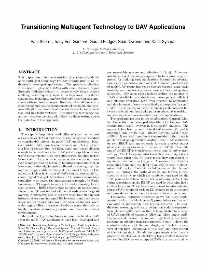
The overall approach described above has been imple-mented within the Machinetta[7] proxy infrastructure andevaluated in increasingly high fidelity testbeds. The coor-dination reasoning and state estimation code is separatedfrom the auto-pilot code so that it is applicable to a rangeof UAVs capable of waypoint following. More importantly,the same code is used on low and high fidelity test beds,allowing an effective transition process. Figure 1 shows thecontrol interface, with the map display on the left, cameraview at top right (simulated, in this case) and filter outputat the bottom right. Simulation experiments show the ap-proach to be effective at identifying likely emitter locationsand sending EO-camera equipped UAVs to areas as small as
100m across.The industrial partner in the collaboration, L-3 Commu-
nications Integrated Systems (L-3/IS), integrated the UAVsystem, including the Machinetta software and algorithmsdeveloped by CMU, communications interfaces, Procerus60” UAV platforms with autopilot and camera, RSSI sen-sors, and ground station. To validate the behavior and ro-bustness of the resulting system, L-3/IS developed a highfidelity simulation environment with OpNet and performedlive flight experiments. The high fidelity simulation environ-ment, besides providing for performance characterization,yielded some unexpected benefits including detecting differ-ences in model assumptions between L-3/IS and CMU, andthe ability to analyze and correct emergent behaviors (i.e.,undesired system behaviors that result from complex inter-action of the sub-systems and environment). With tighterFAA restrictions on live flight testing, having a high fidelitysimulation environment becomes even more important.
Figure 1: Operator interface station showing mapview, camera view and filter output.
2. PROBLEMOur collaborative research focused on the problem of lo-
calizing an unknown number of RF emitters using a team ofUAVs. Most UAVs in this team are assumed to have RSSIsensors which measure RF signal strength at a particular fre-quency band. A small number of UAVs are outfitted withEO sensors capable of streaming video back to a user. Weassume that the environment is too large to feasibly searchusing EO sensors alone. The UAVs must maintain a be-lief over the state of all emitters in the environment in adecentralized manner.
The emitters are represented by the set: E = {e1 . . . en}where n is not known to the team of UAVs. Emitters are allassumed to be emitting at a single known frequency.1 Emit-ters are mobile and emit intermittently. The homogeneousUAVs are represented by the set: U = {u1 . . . um}. Each ui
flies a path given by ~ui(t). During flight a UAV takes sensor
readings, zt( ~loc) which are the received signal power at a
location ~loc = {x, y, z} where {x, y, z} gives the Euclideancoordinates of a point in space relative to a fixed origin.
The sensor readings taken by the ith UAV, up until timet are zi
t0 . . . zit. Each UAV maintains a posterior distribu-
tion P over emitter locations given by P it (e1 . . . en|zi
t0 . . . zit).
1This will be relaxed in future work.
The UAVs proactively share sensor readings to improve eachother’s posterior distribution. At time t each ui can sendsome subset of locally sensed readings: ~zi
t ⊂ zit0 . . . zi
t.The true configuration of the emitters in the environment
at time t is represented as a distribution Q such that
Qt(e1 . . . en) = 1
when e1 . . . en gives the true configuration of the emitters att. The objective is to minimize the divergence between theteam belief and the true state of the emitters, while mini-mizing the cost of UAV flight path, and minimizing the totalnumber of messages shared between UAVs. The followingfunction expresses this mathematically:
min~ui
Xt
Xui∈U
β1Cost(~ui(t)) + β2DKL(P it ‖Q) + β3|~zi
t|
where DKL denotes the the Kullback Leibler divergence andβ1...3 are weights which control the importance of the indi-vidual factors in the optimization process.
When P indicates the location of emitters to within a“rea-sonable”distance, EO assets should be sent to the estimatedlocation to provide a video feed back to an operator who candetermine the nature of the emitter. The earlier the EO as-sets are taking video of the emitter the better. However, theadvantage of sending EO assets early can be mitigated byrequiring that too large of an area be covered by video orby sending assets to areas where there are no emitters, i.e.,false positives.
2.1 RSSI SensorRSSI measurements are available with many transceiver
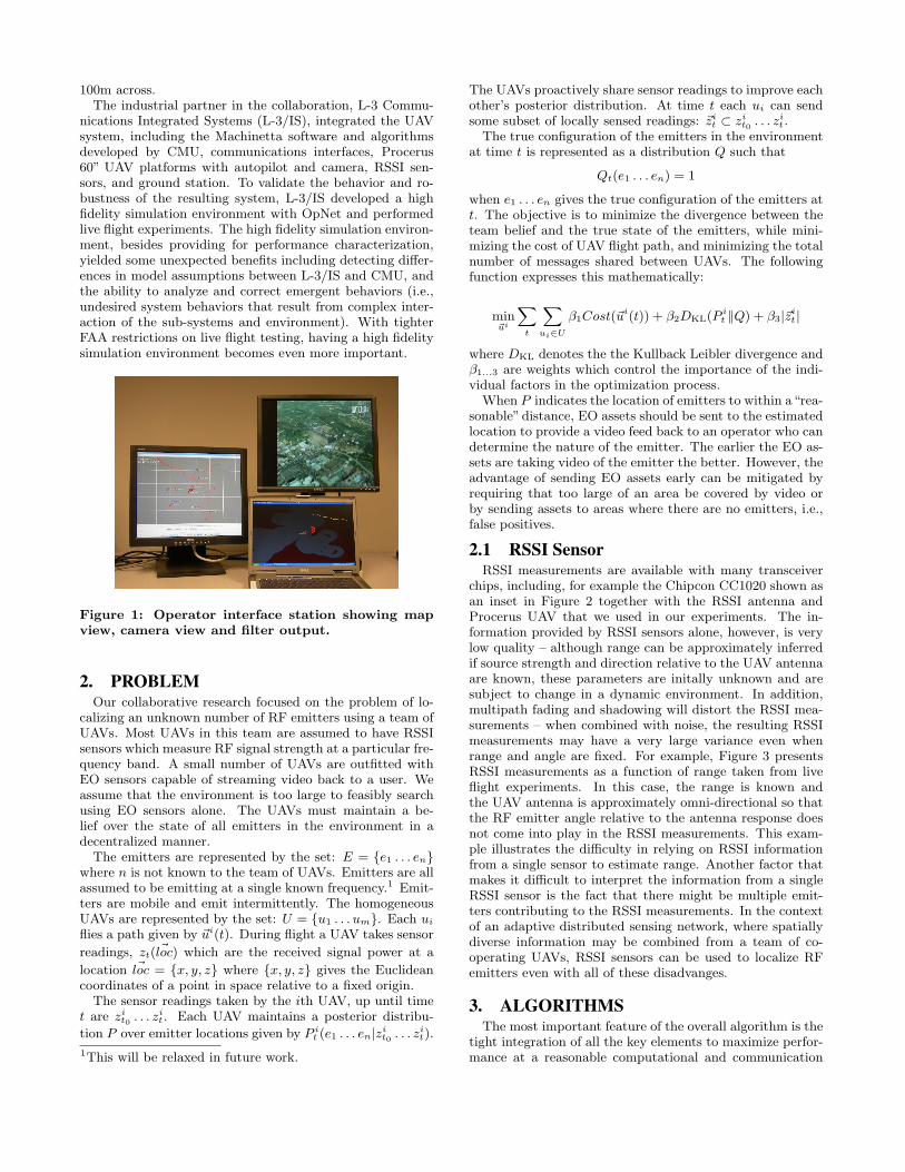
chips, including, for example the Chipcon CC1020 shown asan inset in Figure 2 together with the RSSI antenna andProcerus UAV that we used in our experiments. The in-formation provided by RSSI sensors alone, however, is verylow quality – although range can be approximately inferredif source strength and direction relative to the UAV antennaare known, these parameters are initally unknown and aresubject to change in a dynamic environment. In addition,multipath fading and shadowing will distort the RSSI mea-surements – when combined with noise, the resulting RSSImeasurements may have a very large variance even whenrange and angle are fixed. For example, Figure 3 presentsRSSI measurements as a function of range taken from liveflight experiments. In this case, the range is known andthe UAV antenna is approximately omni-directional so thatthe RF emitter angle relative to the antenna response doesnot come into play in the RSSI measurements. This exam-ple illustrates the difficulty in relying on RSSI informationfrom a single sensor to estimate range. Another factor thatmakes it difficult to interpret the information from a singleRSSI sensor is the fact that there might be multiple emit-ters contributing to the RSSI measurements. In the contextof an adaptive distributed sensing network, where spatiallydiverse information may be combined from a team of co-operating UAVs, RSSI sensors can be used to localize RFemitters even with all of these disadvanges.
3. ALGORITHMSThe most important feature of the overall algorithm is the
tight integration of all the key elements to maximize perfor-mance at a reasonable computational and communication
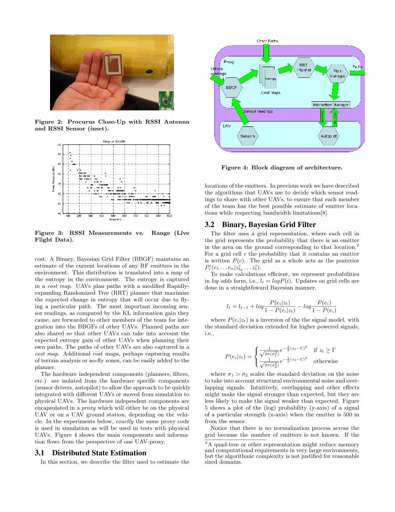
Figure 2: Procurus Close-Up with RSSI Antennaand RSSI Sensor (inset).
Figure 3: RSSI Measurements vs. Range (LiveFlight Data).
cost. A Binary, Bayesian Grid Filter (BBGF) maintains anestimate of the current locations of any RF emitters in theenvironment. This distribution is translated into a map ofthe entropy in the environment. The entropy is capturedin a cost map. UAVs plan paths with a modified Rapidly-expanding Randomized Tree (RRT) planner that maximizethe expected change in entropy that will occur due to fly-ing a particular path. The most important incoming sen-sor readings, as computed by the KL information gain theycause, are forwarded to other members of the team for inte-gration into the BBGFs of other UAVs. Planned paths arealso shared so that other UAVs can take into account theexpected entropy gain of other UAVs when planning theirown paths. The paths of other UAVs are also captured in acost map. Additional cost maps, perhaps capturing resultsof terrain analysis or no-fly zones, can be easily added to theplanner.
The hardware independent components (planners, filters,etc.) are isolated from the hardware specific components(sensor drivers, autopilot) to allow the approach to be quicklyintegrated with different UAVs or moved from simulation tophysical UAVs. The hardware independent components areencapsulated in a proxy which will either be on the physicalUAV or on a UAV ground station, depending on the vehi-cle. In the experiments below, exactly the same proxy codeis used in simulation as will be used in tests with physicalUAVs. Figure 4 shows the main components and informa-tion flows from the perspective of one UAV-proxy.
3.1 Distributed State EstimationIn this section, we describe the filter used to estimate the
Figure 4: Block diagram of architecture.
locations of the emitters. In previous work we have describedthe algorithms that UAVs use to decide which sensor read-ings to share with other UAVs, to ensure that each memberof the team has the best possible estimate of emitter loca-tions while respecting bandwidth limitations[8].
3.2 Binary, Bayesian Grid FilterThe filter uses a grid representation, where each cell in
the grid represents the probability that there is an emitterin the area on the ground corresponding to that location.2
For a grid cell c the probability that it contains an emitteris written P (c). The grid as a whole acts as the posteriorP i
t (e1 . . . en|zit0 . . . zi
t).To make calculations efficient, we represent probabilities
in log odds form, i.e., lt = logP (i). Updates on grid cells aredone in a straightfoward Bayesian manner.
lt = lt−1 + logP (ei|zt)
1− P (ei|zt)− log
P (ei)
1− P (ei)
where P (ei|zt) is a inversion of the the signal model, withthe standard deviation extended for higher powered signals,i.e.,
P (ei|zt) =
8<:1√
2π(σ21)
e−12 (zt−Γ)2 if zt ≥ Γ
1√2π(σ2
2)e−
12 (zt−Γ)2 otherwise
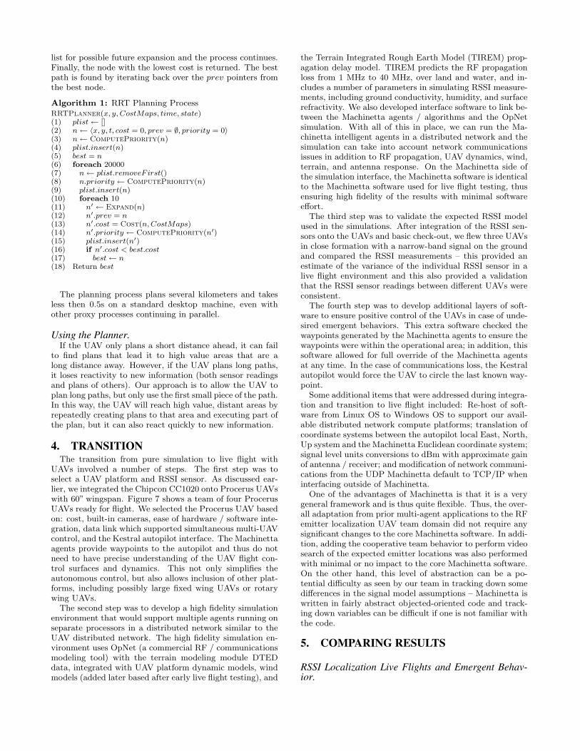
where σ1 > σ2 scales the standard deviation on the noiseto take into account structural environmental noise and over-lapping signals. Intuitively, overlapping and other effectsmight make the signal stronger than expected, but they areless likely to make the signal weaker than expected. Figure5 shows a plot of the (log) probability (y-axis) of a signalof a particular strength (x-axis) when the emitter is 500 mfrom the sensor.
Notice that there is no normalization process across thegrid because the number of emitters is not known. If the2A quad-tree or other representation might reduce memoryand computational requirements in very large environments,but the algorithmic complexity is not justified for reasonablesized domains.
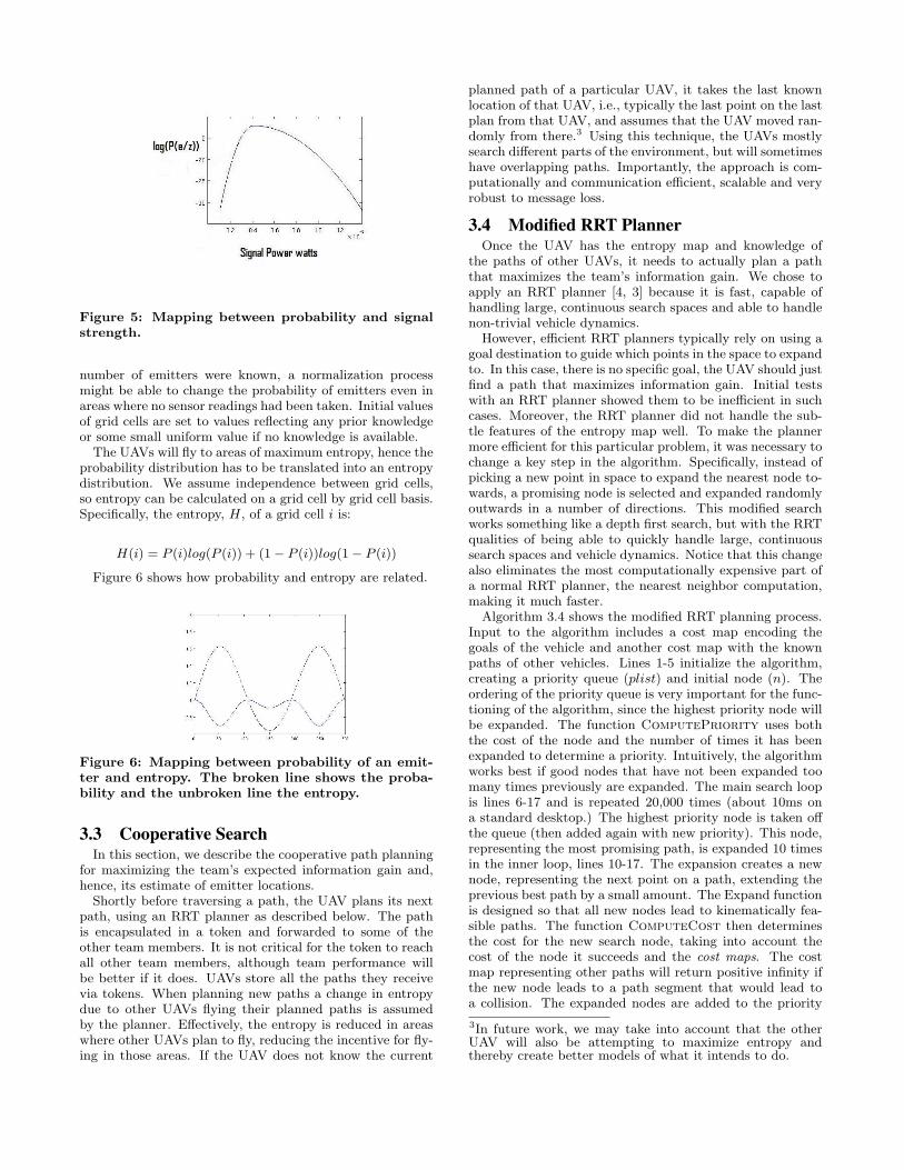
Figure 5: Mapping between probability and signalstrength.
number of emitters were known, a normalization processmight be able to change the probability of emitters even inareas where no sensor readings had been taken. Initial valuesof grid cells are set to values reflecting any prior knowledgeor some small uniform value if no knowledge is available.
The UAVs will fly to areas of maximum entropy, hence theprobability distribution has to be translated into an entropydistribution. We assume independence between grid cells,so entropy can be calculated on a grid cell by grid cell basis.Specifically, the entropy, H, of a grid cell i is:
H(i) = P (i)log(P (i)) + (1− P (i))log(1− P (i))
Figure 6 shows how probability and entropy are related.
Figure 6: Mapping between probability of an emit-ter and entropy. The broken line shows the proba-bility and the unbroken line the entropy.
3.3 Cooperative SearchIn this section, we describe the cooperative path planning
for maximizing the team’s expected information gain and,hence, its estimate of emitter locations.
Shortly before traversing a path, the UAV plans its nextpath, using an RRT planner as described below. The pathis encapsulated in a token and forwarded to some of theother team members. It is not critical for the token to reachall other team members, although team performance willbe better if it does. UAVs store all the paths they receivevia tokens. When planning new paths a change in entropydue to other UAVs flying their planned paths is assumedby the planner. Effectively, the entropy is reduced in areaswhere other UAVs plan to fly, reducing the incentive for fly-ing in those areas. If the UAV does not know the current
planned path of a particular UAV, it takes the last knownlocation of that UAV, i.e., typically the last point on the lastplan from that UAV, and assumes that the UAV moved ran-domly from there.3 Using this technique, the UAVs mostlysearch different parts of the environment, but will sometimeshave overlapping paths. Importantly, the approach is com-putationally and communication efficient, scalable and veryrobust to message loss.
3.4 Modified RRT PlannerOnce the UAV has the entropy map and knowledge of
the paths of other UAVs, it needs to actually plan a paththat maximizes the team’s information gain. We chose toapply an RRT planner [4, 3] because it is fast, capable ofhandling large, continuous search spaces and able to handlenon-trivial vehicle dynamics.
However, efficient RRT planners typically rely on using agoal destination to guide which points in the space to expandto. In this case, there is no specific goal, the UAV should justfind a path that maximizes information gain. Initial testswith an RRT planner showed them to be inefficient in suchcases. Moreover, the RRT planner did not handle the sub-tle features of the entropy map well. To make the plannermore efficient for this particular problem, it was necessary tochange a key step in the algorithm. Specifically, instead ofpicking a new point in space to expand the nearest node to-wards, a promising node is selected and expanded randomlyoutwards in a number of directions. This modified searchworks something like a depth first search, but with the RRTqualities of being able to quickly handle large, continuoussearch spaces and vehicle dynamics. Notice that this changealso eliminates the most computationally expensive part ofa normal RRT planner, the nearest neighbor computation,making it much faster.
Algorithm 3.4 shows the modified RRT planning process.Input to the algorithm includes a cost map encoding thegoals of the vehicle and another cost map with the knownpaths of other vehicles. Lines 1-5 initialize the algorithm,creating a priority queue (plist) and initial node (n). Theordering of the priority queue is very important for the func-tioning of the algorithm, since the highest priority node willbe expanded. The function ComputePriority uses boththe cost of the node and the number of times it has beenexpanded to determine a priority. Intuitively, the algorithmworks best if good nodes that have not been expanded toomany times previously are expanded. The main search loopis lines 6-17 and is repeated 20,000 times (about 10ms ona standard desktop.) The highest priority node is taken offthe queue (then added again with new priority). This node,representing the most promising path, is expanded 10 timesin the inner loop, lines 10-17. The expansion creates a newnode, representing the next point on a path, extending theprevious best path by a small amount. The Expand functionis designed so that all new nodes lead to kinematically fea-sible paths. The function ComputeCost then determinesthe cost for the new search node, taking into account thecost of the node it succeeds and the cost maps. The costmap representing other paths will return positive infinity ifthe new node leads to a path segment that would lead toa collision. The expanded nodes are added to the priority
3In future work, we may take into account that the otherUAV will also be attempting to maximize entropy andthereby create better models of what it intends to do.
list for possible future expansion and the process continues.Finally, the node with the lowest cost is returned. The bestpath is found by iterating back over the prev pointers fromthe best node.
Algorithm 1: RRT Planning ProcessRRTPlanner(x, y, CostMaps, time, state)(1) plist← [](2) n← 〈x, y, t, cost = 0, prev = ∅, priority = 0〉(3) n← ComputePriority(n)(4) plist.insert(n)(5) best = n(6) foreach 20000(7) n← plist.removeF irst()(8) n.priority ← ComputePriority(n)(9) plist.insert(n)(10) foreach 10(11) n′ ← Expand(n)(12) n′.prev = n(13) n′.cost = Cost(n, CostMaps)(14) n′.priority ← ComputePriority(n′)(15) plist.insert(n′)(16) if n′.cost < best.cost(17) best← n(18) Return best
The planning process plans several kilometers and takesless then 0.5s on a standard desktop machine, even withother proxy processes continuing in parallel.
Using the Planner.If the UAV only plans a short distance ahead, it can fail
to find plans that lead it to high value areas that are along distance away. However, if the UAV plans long paths,it loses reactivity to new information (both sensor readingsand plans of others). Our approach is to allow the UAV toplan long paths, but only use the first small piece of the path.In this way, the UAV will reach high value, distant areas byrepeatedly creating plans to that area and executing part ofthe plan, but it can also react quickly to new information.
4. TRANSITIONThe transition from pure simulation to live flight with
UAVs involved a number of steps. The first step was toselect a UAV platform and RSSI sensor. As discussed ear-lier, we integrated the Chipcon CC1020 onto Procerus UAVswith 60” wingspan. Figure 7 shows a team of four ProcerusUAVs ready for flight. We selected the Procerus UAV basedon: cost, built-in cameras, ease of hardware / software inte-gration, data link which supported simultaneous multi-UAVcontrol, and the Kestral autopilot interface. The Machinettaagents provide waypoints to the autopilot and thus do notneed to have precise understanding of the UAV flight con-trol surfaces and dynamics. This not only simplifies theautonomous control, but also allows inclusion of other plat-forms, including possibly large fixed wing UAVs or rotarywing UAVs.
The second step was to develop a high fidelity simulationenvironment that would support multiple agents running onseparate processors in a distributed network similar to theUAV distributed network. The high fidelity simulation en-vironment uses OpNet (a commercial RF / communicationsmodeling tool) with the terrain modeling module DTEDdata, integrated with UAV platform dynamic models, windmodels (added later based after early live flight testing), and
the Terrain Integrated Rough Earth Model (TIREM) prop-agation delay model. TIREM predicts the RF propagationloss from 1 MHz to 40 MHz, over land and water, and in-cludes a number of parameters in simulating RSSI measure-ments, including ground conductivity, humidity, and surfacerefractivity. We also developed interface software to link be-tween the Machinetta agents / algorithms and the OpNetsimulation. With all of this in place, we can run the Ma-chinetta intelligent agents in a distributed network and thesimulation can take into account network communicationsissues in addition to RF propagation, UAV dynamics, wind,terrain, and antenna response. On the Machinetta side ofthe simulation interface, the Machinetta software is identicalto the Machinetta software used for live flight testing, thusensuring high fidelity of the results with minimal softwareeffort.
The third step was to validate the expected RSSI modelused in the simulations. After integration of the RSSI sen-sors onto the UAVs and basic check-out, we flew three UAVsin close formation with a narrow-band signal on the groundand compared the RSSI measurements – this provided anestimate of the variance of the individual RSSI sensor in alive flight environment and this also provided a validationthat the RSSI sensor readings between different UAVs wereconsistent.
The fourth step was to develop additional layers of soft-ware to ensure positive control of the UAVs in case of unde-sired emergent behaviors. This extra software checked thewaypoints generated by the Machinetta agents to ensure thewaypoints were within the operational area; in addition, thissoftware allowed for full override of the Machinetta agentsat any time. In the case of communications loss, the Kestralautopilot would force the UAV to circle the last known way-point.
Some additional items that were addressed during integra-tion and transition to live flight included: Re-host of soft-ware from Linux OS to Windows OS to support our avail-able distributed network compute platforms; translation ofcoordinate systems between the autopilot local East, North,Up system and the Machinetta Euclidean coordinate system;signal level units conversions to dBm with approximate gainof antenna / receiver; and modification of network communi-cations from the UDP Machinetta default to TCP/IP wheninterfacing outside of Machinetta.
One of the advantages of Machinetta is that it is a verygeneral framework and is thus quite flexible. Thus, the over-all adaptation from prior multi-agent applications to the RFemitter localization UAV team domain did not require anysignificant changes to the core Machinetta software. In addi-tion, adding the cooperative team behavior to perform videosearch of the expected emitter locations was also performedwith minimal or no impact to the core Machinetta software.On the other hand, this level of abstraction can be a po-tential difficulty as seen by our team in tracking down somedifferences in the signal model assumptions – Machinetta iswritten in fairly abstract objected-oriented code and track-ing down variables can be difficult if one is not familiar withthe code.
5. COMPARING RESULTS
RSSI Localization Live Flights and Emergent Behav-ior.
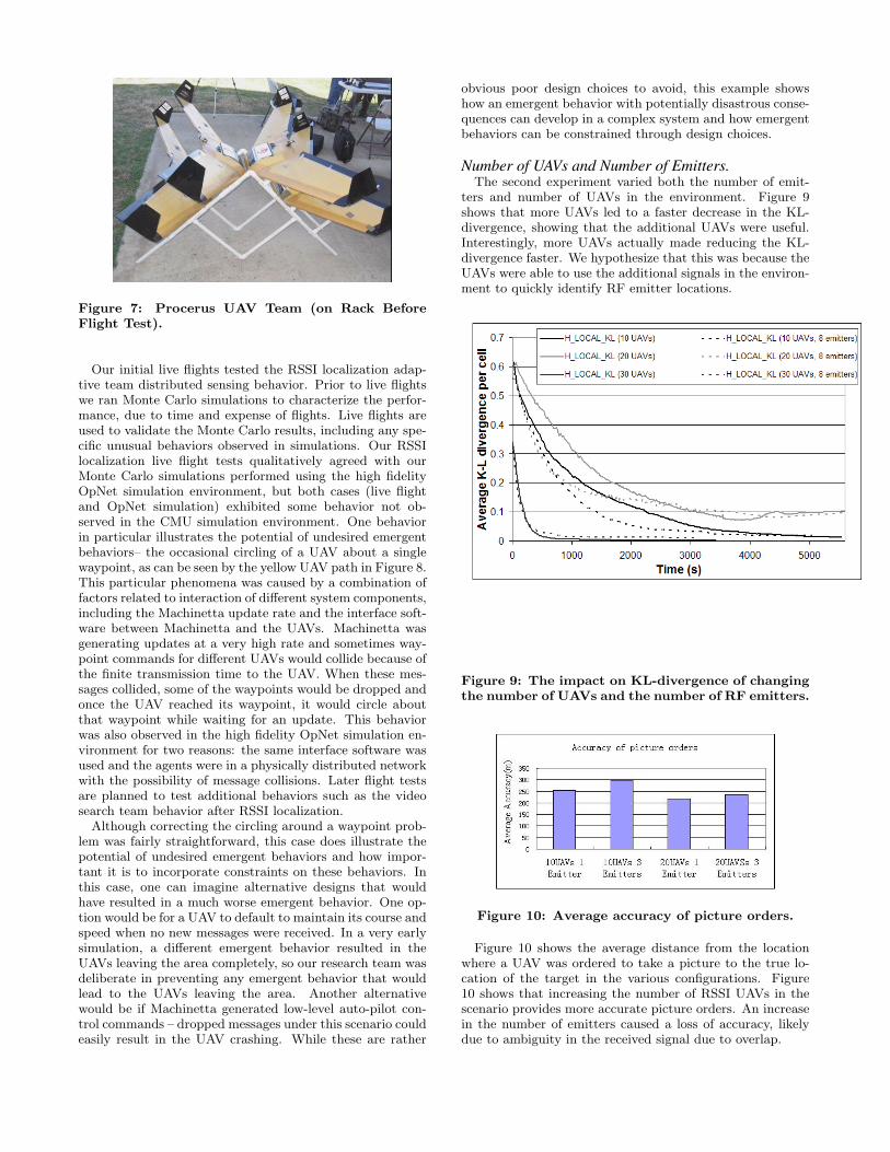
Figure 7: Procerus UAV Team (on Rack BeforeFlight Test).
Our initial live flights tested the RSSI localization adap-tive team distributed sensing behavior. Prior to live flightswe ran Monte Carlo simulations to characterize the perfor-mance, due to time and expense of flights. Live flights areused to validate the Monte Carlo results, including any spe-cific unusual behaviors observed in simulations. Our RSSIlocalization live flight tests qualitatively agreed with ourMonte Carlo simulations performed using the high fidelityOpNet simulation environment, but both cases (live flightand OpNet simulation) exhibited some behavior not ob-served in the CMU simulation environment. One behaviorin particular illustrates the potential of undesired emergentbehaviors– the occasional circling of a UAV about a singlewaypoint, as can be seen by the yellow UAV path in Figure 8.This particular phenomena was caused by a combination offactors related to interaction of different system components,including the Machinetta update rate and the interface soft-ware between Machinetta and the UAVs. Machinetta wasgenerating updates at a very high rate and sometimes way-point commands for different UAVs would collide because ofthe finite transmission time to the UAV. When these mes-sages collided, some of the waypoints would be dropped andonce the UAV reached its waypoint, it would circle aboutthat waypoint while waiting for an update. This behaviorwas also observed in the high fidelity OpNet simulation en-vironment for two reasons: the same interface software wasused and the agents were in a physically distributed networkwith the possibility of message collisions. Later flight testsare planned to test additional behaviors such as the videosearch team behavior after RSSI localization.
Although correcting the circling around a waypoint prob-lem was fairly straightforward, this case does illustrate thepotential of undesired emergent behaviors and how impor-tant it is to incorporate constraints on these behaviors. Inthis case, one can imagine alternative designs that wouldhave resulted in a much worse emergent behavior. One op-tion would be for a UAV to default to maintain its course andspeed when no new messages were received. In a very earlysimulation, a different emergent behavior resulted in theUAVs leaving the area completely, so our research team wasdeliberate in preventing any emergent behavior that wouldlead to the UAVs leaving the area. Another alternativewould be if Machinetta generated low-level auto-pilot con-trol commands – dropped messages under this scenario couldeasily result in the UAV crashing. While these are rather
obvious poor design choices to avoid, this example showshow an emergent behavior with potentially disastrous conse-quences can develop in a complex system and how emergentbehaviors can be constrained through design choices.
Number of UAVs and Number of Emitters.The second experiment varied both the number of emit-
ters and number of UAVs in the environment. Figure 9shows that more UAVs led to a faster decrease in the KL-divergence, showing that the additional UAVs were useful.Interestingly, more UAVs actually made reducing the KL-divergence faster. We hypothesize that this was because theUAVs were able to use the additional signals in the environ-ment to quickly identify RF emitter locations.
Figure 9: The impact on KL-divergence of changingthe number of UAVs and the number of RF emitters.
Figure 10: Average accuracy of picture orders.
Figure 10 shows the average distance from the locationwhere a UAV was ordered to take a picture to the true lo-cation of the target in the various configurations. Figure10 shows that increasing the number of RSSI UAVs in thescenario provides more accurate picture orders. An increasein the number of emitters caused a loss of accuracy, likelydue to ambiguity in the received signal due to overlap.
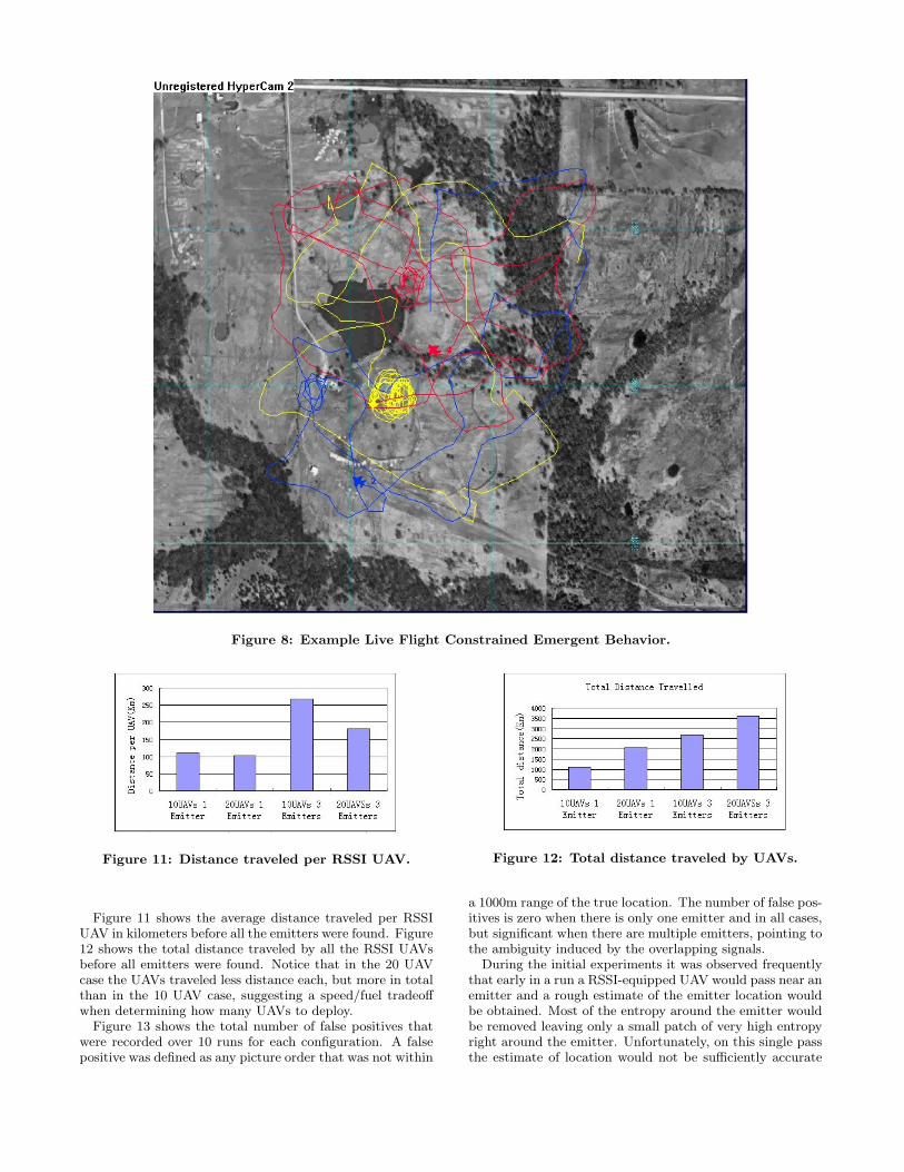
Figure 8: Example Live Flight Constrained Emergent Behavior.
Figure 11: Distance traveled per RSSI UAV.
Figure 11 shows the average distance traveled per RSSIUAV in kilometers before all the emitters were found. Figure12 shows the total distance traveled by all the RSSI UAVsbefore all emitters were found. Notice that in the 20 UAVcase the UAVs traveled less distance each, but more in totalthan in the 10 UAV case, suggesting a speed/fuel tradeoffwhen determining how many UAVs to deploy.
Figure 13 shows the total number of false positives thatwere recorded over 10 runs for each configuration. A falsepositive was defined as any picture order that was not within
Figure 12: Total distance traveled by UAVs.
a 1000m range of the true location. The number of false pos-itives is zero when there is only one emitter and in all cases,but significant when there are multiple emitters, pointing tothe ambiguity induced by the overlapping signals.
During the initial experiments it was observed frequentlythat early in a run a RSSI-equipped UAV would pass near anemitter and a rough estimate of the emitter location wouldbe obtained. Most of the entropy around the emitter wouldbe removed leaving only a small patch of very high entropyright around the emitter. Unfortunately, on this single passthe estimate of location would not be sufficiently accurate
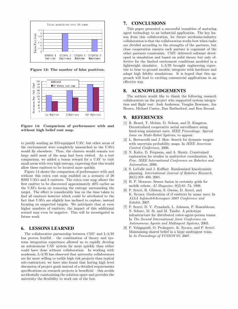
Figure 13: The number of false positives.
Figure 14: Comparison of performance with andwithout high belief cost map.
to justify sending an EO-equipped UAV, but other areas ofthe environment were completely unsearched so the UAVswould fly elsewhere. Thus, the clusters would remain toolarge until most of the map had been visited. As a testcomparison, we added a bonus reward for a UAV to visitsmall areas with very high entropy, expecting that this wouldallow these emitters to be located more quickly.
Figure 14 shows the comparison of performance with andwithout this extra cost map enabled on a scenario of 20RSSI UAVs and 3 emitters. The extra cost map allows thefirst emitter to be discovered approximately 40% earlier asthe UAVs focus on removing the entropy surrounding thetarget. The effect is considerably less on the time taken tofind all emitters however which could be attributed to thefact that UAVs are slightly less inclined to explore, insteadfocusing on suspected targets. We anticipate that at evenhigher numbers of emitters, the impact of this additionalreward may even be negative. This will be investigated infuture work.
6. LESSONS LEARNEDThe collaborative partnership between CMU and L-3/IS
has proven fruitful – the combination of theory and sys-tems integration experience allowed us to rapidly developan autonomous UAV system far more quickly than eithercould have done without collaboration. In working withacademia, L-3/IS has observed that university collaboratorsare far more willing to tackle high risk projects than typicalsub-contractors; we have also found that having high leveldiscussion of project goals instead of a detailed requirementsspecifications on research projects is beneficial – this avoidsaccidentally constraining the solution space and provides theuniversity the flexibility to work out of the box.
7. CONCLUSIONSThis paper presented a successful transition of maturing
agent technology to an industrial application. The key les-son from this collaboration, for future acedemia-industrycollaboration is that the collaboration works best when tasksare divided according to the strengths of the partners, butclose cooperation ensures each partner is cognizant of theother partners constraints. CMU delivered software devel-oped in simulation and based on solid theory but only ef-fective for the limited enviroment conditions modeled in alightweight simulator. L-3/IS brought engineering exper-tise to bear to ground models, integrate with hardware andadapt high fidelity simulations. It is hoped that this ap-proach will lead to exciting commercial applications in aneffective way.
8. ACKNOWLEDGEMENTSThe authors would like to thank the following research
collaborators on the project who supported system integra-tion and flight test: Josh Anderson, Vaughn Bowman, JonBrown, Michael Custer, Dan Rutherford, and Ken Stroud.
9. REFERENCES[1] R. Beard, T. Mclain, D. Nelson, and D. Kingston.
Decentralized cooperative aerial surveillance usingfixed-wing miniature uavs. IEEE Proceedings: SpecialIssue on Multi-Robot Systems, to appear.
[2] L. Bertuccelli and J. How. Search for dynamic targetswith uncertain probability maps. In IEEE AmericanControl Conference, 2006.
[3] N. Kalra, D. Ferguson, and A. Stentz. Constrainedexploration for studies in multirobot coordination. InProc. IEEE International Conference on Robotics andAutomation, 2006.
[4] S. LaValle and J. Kuffner. Randomized kinodynamicplanning. International Journal of Robotics Research,20(5):378–400, 2001.
[5] H. P. Moravec. Sensor fusion in certainty grids formobile robots. AI Magazine, 9(2):61–74, 1998.
[6] P. Scerri, R. Glinton, S. Owens, D. Scerri, andK. Sycara. Geolocation of rf emitters by many uavs. InAIAA Infotech@Aerospace 2007 Conference andExhibit, 2007.
[7] P. Scerri, D. V. Pynadath, L. Johnson, P. Rosenbloom,N. Schurr, M. Si, and M. Tambe. A prototypeinfrastructure for distributed robot-agent-person teams.In The Second International Joint Conference onAutonomous Agents and Multiagent Systems, 2003.
[8] P. Velagapudi, O. Prokopyev, K. Sycara, and P. Scerri.Maintaining shared belief in a large multiagent team.In In Proceedings of FUSION’07, 2007.