Transition dipole moment orientation in films of solution ... · Journal of Materials Chemistry C...
8
Transition dipole moment orientation in films of solution processed fluorescent oligomers Senes, A.; Meskers, S.C.J.; Dijkstra, W.M.; van Franeker, J.J.; Altazin, S.; Wilson, J.S.; Janssen, R.A.J. Published in: Journal of Materials Chemistry C DOI: 10.1039/c5tc03481g Published: 01/01/2016 Document Version Publisher’s PDF, also known as Version of Record (includes final page, issue and volume numbers) Please check the document version of this publication: • A submitted manuscript is the author's version of the article upon submission and before peer-review. There can be important differences between the submitted version and the official published version of record. People interested in the research are advised to contact the author for the final version of the publication, or visit the DOI to the publisher's website. • The final author version and the galley proof are versions of the publication after peer review. • The final published version features the final layout of the paper including the volume, issue and page numbers. Link to publication General rights Copyright and moral rights for the publications made accessible in the public portal are retained by the authors and/or other copyright owners and it is a condition of accessing publications that users recognise and abide by the legal requirements associated with these rights. • Users may download and print one copy of any publication from the public portal for the purpose of private study or research. • You may not further distribute the material or use it for any profit-making activity or commercial gain • You may freely distribute the URL identifying the publication in the public portal ? Take down policy If you believe that this document breaches copyright please contact us providing details, and we will remove access to the work immediately and investigate your claim. Download date: 19. Jul. 2018
Transcript of Transition dipole moment orientation in films of solution ... · Journal of Materials Chemistry C...

Transition dipole moment orientation in films of solutionprocessed fluorescent oligomersSenes, A.; Meskers, S.C.J.; Dijkstra, W.M.; van Franeker, J.J.; Altazin, S.; Wilson, J.S.;Janssen, R.A.J.Published in:Journal of Materials Chemistry C
DOI:10.1039/c5tc03481g
Published: 01/01/2016
Document VersionPublisher’s PDF, also known as Version of Record (includes final page, issue and volume numbers)
Please check the document version of this publication:
• A submitted manuscript is the author's version of the article upon submission and before peer-review. There can be important differencesbetween the submitted version and the official published version of record. People interested in the research are advised to contact theauthor for the final version of the publication, or visit the DOI to the publisher's website.• The final author version and the galley proof are versions of the publication after peer review.• The final published version features the final layout of the paper including the volume, issue and page numbers.
Link to publication
General rightsCopyright and moral rights for the publications made accessible in the public portal are retained by the authors and/or other copyright ownersand it is a condition of accessing publications that users recognise and abide by the legal requirements associated with these rights.
• Users may download and print one copy of any publication from the public portal for the purpose of private study or research. • You may not further distribute the material or use it for any profit-making activity or commercial gain • You may freely distribute the URL identifying the publication in the public portal ?
Take down policyIf you believe that this document breaches copyright please contact us providing details, and we will remove access to the work immediatelyand investigate your claim.
Download date: 19. Jul. 2018

6302 | J. Mater. Chem. C, 2016, 4, 6302--6308 This journal is©The Royal Society of Chemistry 2016
Cite this: J.Mater. Chem. C, 2016,
4, 6302
Transition dipole moment orientation in filmsof solution processed fluorescent oligomers:investigating the influence of molecularanisotropy†
Alessia Senes,*ab Stefan C. J. Meskers,b Wijnand M. Dijkstra,b Jacobus J. van Franeker,bc
Stephane Altazin,d Joanne S. Wilsona and Rene. A. J. Janssen*b
The low light-outcoupling efficiency of organic light emitting diodes (OLEDs) is limiting their performance.
Orientation of the transition dipole moment of the emitting molecules in the plane of the diodes can
improve the luminance of OLEDs. While the orientation of evaporated small-molecule materials has been
studied in the past few years, not much is known about solution processed small molecules and short
oligomers, and it is not clear yet which parameters influence their orientation in the film. In this work we
study a series of short conjugated p-phenylene vinylene oligomers (OPVn), consisting of an increasing
number of repeating phenyl rings (n from 2 to 7), which are introduced into a small-molecule host matrix.
By measuring the angular distribution of p-polarised fluorescence intensity from thin solution processed
films, we determine the average orientation of the transition dipole moment of the emitters in the host
matrix. We find that for longer oligomers (n = 6, 7), the transition dipole moments align more horizontally,
with ratios of horizontally to vertically oriented dipoles up to 80 : 20. The preferential horizontal alignment
is related to the aggregation of the emitter molecules.
Introduction
Nowadays we can find OLEDs in the market in large flat paneldisplays, in smartphones, tablets and other portable consumerelectronics. On a research scale, white light OLEDs for lightingreach high efficiencies of up to 139 lm W�1 and are becomingcommercially available.1 OLEDs have a number of attractivefeatures such as large area, low weight, thinness, flexibility androbustness. One way to reduce their production costs is tochange the deposition technique from thermal evaporationunder vacuum to solution processing in a high-throughput,roll-to-roll deposition process. Also the power efficiencies ofOLEDs can be further improved. An unresolved issue for OLEDsis their light outcoupling efficiency. While the internal quantumefficiency of phosphorescent emitters is close to 100%, the light
outcoupling efficiency is usually around 20%, drastically limitingthe external quantum efficiency (EQE) of the devices. This is dueto various losses inside OLEDs, such as waveguiding of the lightin the substrate and OLED layers, and cathode quenching.2
Various light extraction techniques have proven to be useful inimproving the outcoupling efficiency in OLEDs such as externaloutcoupling foils, internal light extraction layers with a highrefractive index and corrugated cathodes.2 Recently the importanceof the orientation of the transition dipole moment of the emittersin small-molecule materials has become apparent. By changing theorientation of the transition dipole moments of the emittingmolecule from random to predominantly horizontal, in the planedirection, the light outcoupling efficiency can be improved.3–5
Orientation of the transition dipole moment in the plane of thesubstrate can increase the light outcoupling efficiency of the OLEDby 1.5 times compared to devices with randomly oriented emitters.6
Moreover, changing the molecular orientation can also improve thecharge carrier transport in the charge transport layers.7
Most studies on molecular orientation have focused onalignment in vapour deposited films of small-molecule materials.8
One of the factors influencing the orientation is the anisotropyin the molecular shape. It has been observed that molecules witha long, rod-like shape, planar oblate shape or long and windingshape tend to show optical anisotropy in the film.9,10 On theother hand molecules with a more globular shape have optical
a Holst Centre/TNO, High Tech Campus 31, P.O. Box 8550, 5605 KN Eindhoven,
The Netherlands. E-mail: [email protected] Molecular Materials and Nanosystems and Institute for Complex Molecular
Systems, Eindhoven University of Technology, P.O. Box 513, 5600 MB Eindhoven,
The Netherlands. E-mail: [email protected] Dutch Polymer Institute (DPI), P.O. Box 902, 5600 AX Eindhoven, The Netherlandsd Fluxim AG, Winterthur, Switzerland
† Electronic supplementary information (ESI) available: Optical constants of TPBi,absorption spectra of OPVn, and simulation of angle dependent fluorescence.See DOI: 10.1039/c5tc03481g
Received 24th October 2015,Accepted 2nd June 2016
DOI: 10.1039/c5tc03481g
www.rsc.org/MaterialsC
Journal ofMaterials Chemistry C
PAPER
Ope
n A
cces
s A
rtic
le. P
ublis
hed
on 0
2 Ju
ne 2
016.
Dow
nloa
ded
on 0
3/01
/201
7 10
:33:
17.
Thi
s ar
ticle
is li
cens
ed u
nder
a C
reat
ive
Com
mon
s A
ttrib
utio
n 3.
0 U
npor
ted
Lic
ence
.
View Article OnlineView Journal | View Issue
This journal is©The Royal Society of Chemistry 2016 J. Mater. Chem. C, 2016, 4, 6302--6308 | 6303
properties that are almost isotropic.8 Another factor that is reportedto influence the orientation of the molecules is the formation ofC–H� � �N intermolecular hydrogen bonds.11 The hydrogen bondformation can promote the in-plane alignment of the transitiondipole moments.
Also the presence of permanent electrical dipole momentsin molecules may influence the orientation of molecules invapour deposited films. A correlation was found between thepermanent dipole moment and the preferential horizontalorientation of the transition dipole moment in a study of sevendifferent iridium complexes.12 Emitters with a smaller perma-nent dipole moment were found to show a higher degree ofhorizontal orientation of the transition dipole moment. Thiscorrelation likely only holds for a series of molecules with afixed mutual orientation of the transition dipole moment andthe permanent dipole moment. In a recent study an alterna-tive mechanism was proposed for iridium dyes in which theinherent asymmetry at the surface of the growing film, createdby the acetylacetonate ligand of the iridium dye, promotes thealignment of the dopant.13
So far studies on the orientation of transition the dipolemoment in small-molecule materials for OLED applicationshave focused mainly on evaporated materials. For luminescentconjugated polymers preferential horizontal orientation insolution processed layers is known.14–17 High degrees of horizontalorientation have also been reported for a light-emitting hepta-fluorene oligomer in a solution processed host/guest system.18
The preferential orientation of small emitter molecules forOLEDs has been studied by Yokoyama et al. For a number ofsmall molecules they found that the degree of horizontalmolecular orientation of small-molecule spin-coated films isinherently lower than that of the corresponding vacuum evaporatedfilms.19,20
In this study we investigate whether the horizontal alignmentof light emitting oligomeric guests in a small molecule host canbe induced in layers deposited from solution by varying theaspect ratio of the oligomers. We studied a series of p-conjugatedmethyl end-capped p-phenylene vinylene oligomers (OPVn), inwhich the number of phenyl rings, n, varies from 2 to 7 (Fig. 1).The host matrix we use is 2,20,200-benzene-1,3,5-triyltris(1-phenyl-1H-benzimidazole) (TPBi). In evaporated layers, TPBi moleculeshave been shown to be randomly oriented on the substrate.8
ExperimentalMaterials
The synthesis of the OPVn molecules has been described pre-viously.21 TPBi was obtained from Lumtec. The two componentsof the host/guest system were mixed in a 9 : 1 weight ratio anddissolved in chloroform, 1 w/v%. For OPV4, OPV6 and OPV7 alsofilms with a host/guest weight ratio of 49 : 1 were prepared. Themixed solution of TPBi and OPVn was stirred at 40 1C overnightand cooled down before use. Solutions were filtered through a0.22 mm PTFE filter and deposited by spin coating at a speed of1200 rpm on quartz substrates. The layer thickness was around40 nm for all layers, as measured by surface profilometry.
Angular dependent fluorescence
In order to analyse the orientation of the transition dipole momentof the emitters in solution processed layers, we measured theangular dependence of the p-polarised fluorescence intensity. Thesetup used (Fig. 2) was previously described by Brutting et al.22
The layers are excited with the focused light of a 365 nm LED, andthe fluorescent light emitted through the quartz substrate, whichis optically coupled to a quartz hemicylinder through matchedrefractive index oil, is p-polarised using a polarizer and collectedusing a spectrometer. The fluorescence is measured at differentangles, from 01 to 801, in steps of 21. The measurements wereperformed in an inert N2 atmosphere (H2O and O2 o 1 ppm).The measurements were repeated on different samples to ensurereproducible and consistent results.
The optical constants (refractive index, n, and extinctioncoefficient k) of the pure host material (Fig. S1, ESI†) weredetermined experimentally by spectroscopic ellipsometry at variousangles of incidence and transmission intensity measurements at 01(perpendicular incidence). The data were analysed using WoollamCompleteEASE software (version 4.92). Ellipsometry on layers of thepure host did not reveal any indication for optical anisotropy andso the optical properties of the host were taken to be the same in alldirections.
Absorption spectra were obtained from transmission measure-ments on the host/guest films on quartz substrates. For clarity the
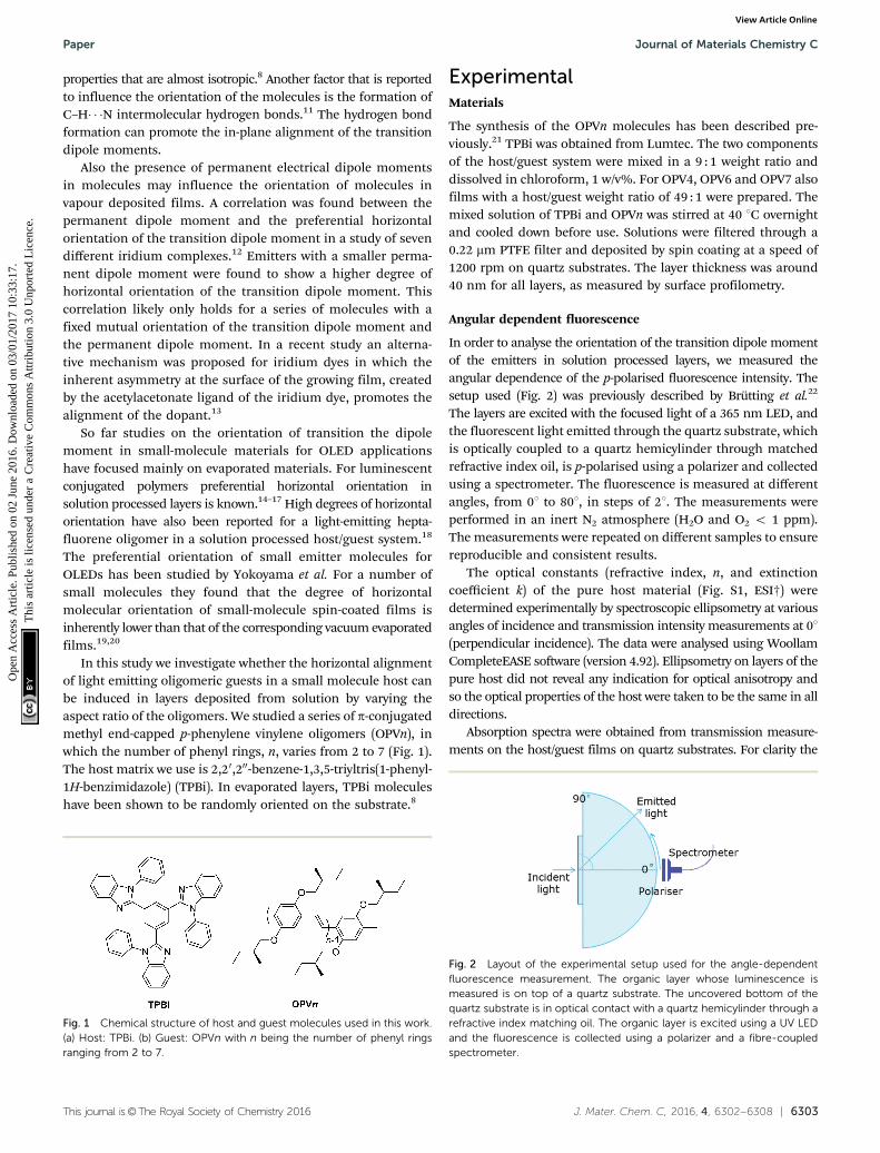
Fig. 1 Chemical structure of host and guest molecules used in this work.(a) Host: TPBi. (b) Guest: OPVn with n being the number of phenyl ringsranging from 2 to 7.
Fig. 2 Layout of the experimental setup used for the angle-dependentfluorescence measurement. The organic layer whose luminescence ismeasured is on top of a quartz substrate. The uncovered bottom of thequartz substrate is in optical contact with a quartz hemicylinder through arefractive index matching oil. The organic layer is excited using a UV LEDand the fluorescence is collected using a polarizer and a fibre-coupledspectrometer.
Paper Journal of Materials Chemistry C
Ope
n A
cces
s A
rtic
le. P
ublis
hed
on 0
2 Ju
ne 2
016.
Dow
nloa
ded
on 0
3/01
/201
7 10
:33:
17.
Thi
s ar
ticle
is li
cens
ed u
nder
a C
reat
ive
Com
mon
s A
ttrib
utio
n 3.
0 U
npor
ted
Lic
ence
.View Article Online
6304 | J. Mater. Chem. C, 2016, 4, 6302--6308 This journal is©The Royal Society of Chemistry 2016
contribution of the host material to the absorption, peaking at306 nm and a baseline were subtracted from the spectra.
The experimental angular dependencies of the p-polarisedfluorescence intensities of the TPBi/OPVn layers were combinedwith the optical constants of pure TPBi and used as input foroptical simulations using Setfos 4.0 (Fluxim AG, Switzerland).Setfos 4.0 solves the Maxwell equations for the set of stackedlayers, with oriented dipole oscillators embedded in the host layeras sources of radiation representing the emitting molecules.23 Bothfar field radiation and near field radiation patterns of the dipolesare simulated. In the modelling it is assumed that photoselectionin the excitation of dipole emitters is absent and that everyfluorescent molecule is excited with equal probability regardlessof its orientation. This is a reasonable assumption because 365 nmexcitation is at higher energy than the lowest energy, parallelpolarized, S0 - S1 absorption band (except for OPV2) as can beenin the optical absorption spectra of the OPVn molecules (Fig. S2,ESI†). Furthermore, the high concentrations of 2 and 10 wt%stimulate energy transfer and randomization among the orienta-tion of excited OPVn molecules before they emit. By comparing tothe experimental data the optical simulations allow quantifying thedegree of orientation of the transition dipole moments.
Microscopy
The host/guest layers for transmission electron microscopy(TEM) were processed from chloroform solutions on top of alayer of poly(3,4-ethylenedioxythiophene):poly(styrene sulfonate)(Clevios PEDOT:PSS, Heraeus) on glass substrates. By immersingthe layer stack in deionized water, the PEDOT:PSS layer isdissolved and the host/guest film floats on the surface. Thehost/guest layer is picked up onto 200 square mesh copper TEM-grids. TEM images were taken on a Tecnai G2 Sphera, operatingat 200 kV, using a magnification of 5000� and a defocus of�10 mm.Atomic force microscopy (AFM) was performed using a VeecoDimension 3100 microscope in tapping mode with a scan rateof 1 Hz and ppp-NCHR-50 tips from Nanosensors, on the samelayers as used in the fluorescence measurements.
Results and discussionTransition dipole moment orientation and layer analysis
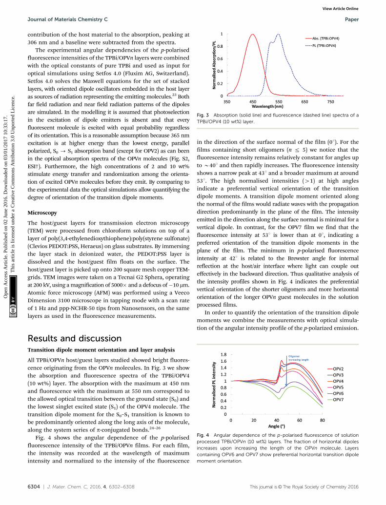
All TPBi/OPVn host/guest layers studied showed bright fluores-cence originating from the OPVn molecules. In Fig. 3 we showthe absorption and fluorescence spectra of the TPBi/OPV4(10 wt%) layer. The absorption with the maximum at 450 nmand fluorescence with the maximum at 550 nm correspond tothe allowed optical transition between the ground state (S0) andthe lowest singlet excited state (S1) of the OPV4 molecule. Thetransition dipole moment for the S0–S1 transition is known tobe predominantly oriented along the long axis of the molecule,along the system series of p-conjugated bonds.24–26
Fig. 4 shows the angular dependence of the p-polarisedfluorescence intensity of the TPBi/OPVn films. For each film,the intensity was recorded at the wavelength of maximumintensity and normalized to the intensity of the fluorescence
in the direction of the surface normal of the film (01). For thefilms containing short oligomers (n r 5) we notice that thefluorescence intensity remains relatively constant for angles upto B401 and then rapidly increases. The fluorescence intensityshows a narrow peak at 431 and a broader maximum at around531. The high normalised intensities (41) at high anglesindicate a preferential vertical orientation of the transitiondipole moments. A transition dipole moment oriented alongthe normal of the films would radiate waves with the propagationdirection predominantly in the plane of the film. The intensityemitted in the direction along the surface normal is minimal for avertical dipole. In contrast, for the OPV7 film we find that thefluorescence intensity at 531 is lower than at 01, indicating apreferred orientation of the transition dipole moments in theplane of the film. The minimum in p-polarised fluorescenceintensity at 421 is related to the Brewster angle for internalreflection at the host/air interface where light can couple outeffectively in the backward direction. Thus qualitative analysis ofthe intensity profiles shown in Fig. 4 indicates the preferentialvertical orientation of the shorter oligomers and more horizontalorientation of the longer OPVn guest molecules in the solutionprocessed films.
In order to quantify the orientation of the transition dipolemoments we combine the measurements with optical simula-tion of the angular intensity profile of the p-polarized emission.
Fig. 3 Absorption (solid line) and fluorescence (dashed line) spectra of aTPBi/OPV4 (10 wt%) layer.
Fig. 4 Angular dependence of the p-polarised fluorescence of solutionprocessed TPBi/OPVn (10 wt%) layers. The fraction of horizontal dipolesincreases upon increasing the length of the OPVn molecule. Layerscontaining OPV6 and OPV7 show preferential horizontal transition dipolemoment orientation.
Journal of Materials Chemistry C Paper
Ope
n A
cces
s A
rtic
le. P
ublis
hed
on 0
2 Ju
ne 2
016.
Dow
nloa
ded
on 0
3/01
/201
7 10
:33:
17.
Thi
s ar
ticle
is li
cens
ed u
nder
a C
reat
ive
Com
mon
s A
ttrib
utio
n 3.
0 U
npor
ted
Lic
ence
.View Article Online

This journal is©The Royal Society of Chemistry 2016 J. Mater. Chem. C, 2016, 4, 6302--6308 | 6305
In Fig. 5 we show simulated intensity profiles for differentorientational distributions of transition dipole moments. Forfully randomly oriented transition dipole moments with anisotropic distribution function, the relative intensity at 571 is1.1. For the case where all transition dipoles are alignedperfectly in the plane of the film, the simulations predict amuch lower relative intensity of the p-polarized fluorescencewith a local maximum of 0.55 at 581. Fig. 5 also shows theexperimental data for the films containing 10 wt% OPV7. Thedata points lie in between the simulated traces for random andhorizontal orientation, indicating a partial alignment of thetransition dipole moments in the horizontal direction.
Using optical simulations we calculated the p-polarizedintensity profile originating from the fluorescence of the organiclayer assuming a distribution of transition dipole momentsoriented along the vertical and horizontal directions with adjus-table weight coefficients (yv and yh) to describe the prevalence ofeither of these orientations. For a fully random distribution oftransition dipole moments, the coefficients for vertical andhorizontal orientation are yv = 0.33 and yh = 0.66, respectively.Taking the experimental data for the TPBi/OPV7 (10 wt%) andvarying the coefficients in the simulations we find that theexperimental data are best described by yv = 0.2 and yh = 0.8,i.e. a combination of 20% vertically and 80% horizontally alignedtransition dipole moments. We note that although we considerthe fit acceptable for the purpose of determining yv, it is notperfect. In the small-angle region the simulations predict a lowerintensity than that found experimentally, and the peak in thehigh-angle range is at slightly higher angles in the simulationsthan in the experiment. Slight variations in the thickness of thefilms in the simulations did not affect these deviations.
The angular dependence of the p-polarised fluorescence profilesof the layers was analysed for all OPVn compounds The comparisonof the experimental and simulated angular dependence of thep-polarised fluorescence for the other OPVn/TPBi blends can befound in the ESI.† The fitting, obtained through the simulationsoftware Setfos, is based on a chi-square minimization thattakes all the measurement points into account between 08 and801. A Levenberg–Marquardt algorithm is used to solve thisnon-linear problem. The simulated curves (see ESI†) do not givea perfect fit to the data (which are consistently somewhat
overestimated at angles below 201 and between 508 and 608,and underestimated for complementary angles), but reproducethe salient features. The orientation coefficients yv obtained inthis way are shown in Fig. 6. In the layers containing theshortest emitters, with n = 2 to 5, there is a bias towards thevertical orientation of the fluorescent molecules (yv 4 0.33).The physical basis for this preferred vertical orientation ispresently not known. We cannot exclude that the observedyv 4 0.33 is a consequence of the density of photon modesfavouring radiative decay from vertically aligned dipoles inthese dielectric microcavity structures.27,28 Layers containing10 wt% of OPV6 or OPV7 show a predominance of horizontallyoriented emitting transition dipole moments (yv o 0.33).
In order to understand why the longest emitters show apreferential horizontal orientation of the emitting transitiondipole moments, the photophysical properties and the mor-phology of the layers containing OPV6 or OPV7 were studied inmore detail. The absorption spectra of OPV6 and OPV7 shownin Fig. 7 reveal a maximum in intensity around a wavelength of430 nm for both oligomers. When dissolved in 2-MeTHF, OPV6and OPV7 show maximum absorption at wavelengths of 466and 473 nm, respectively (Fig. S2, ESI†).29 The absorptionmaximum of OPV6 and OPV7 in the film is thus strongly blueshifted even in comparison with the absorption maximum ofOPV4 in the film. Furthermore the absorption spectra of thefilms containing 10 wt% of these longer oligomers also show ashift of the onset of absorption to longer wavelengths incomparison with the solution data as shown in Fig. 7. Thesespectroscopic features are characteristic of the formation ofH-type aggregates for OPV6 and OPV7 in 10 wt% films withTPBi.30 The presence of aggregates is further supported byfluorescence measurements. The spectra show a red shift ofthe emission band of the films in comparison to solution,which is consistent with H-type aggregation.30
Aggregation can be suppressed by lowering the concen-tration of the oligomers in the solution used to prepare thefilms. Fig. 8 shows the fluorescence spectra of TPBi/OPV6 andTPBi/OPV7 blends prepared from solutions with a reducedweight content of the oligomers (2 wt% instead of 10 wt%).For the films with a lower loading we find that the maximum in
Fig. 5 Experimental angular dependence of the p-polarised fluorescenceintensity for a solution processed TPBi/OPV7 (10 wt%) layer (solid circles)compared to simulated profiles with different anisotropy factors (solid linefor yv = 0.2; dash-dotted line for fully horizontal orientation, yv = 0; dashedline for isotropic orientation, yv = 0.33).
Fig. 6 Coefficient for vertical orientation (yv) of transition dipole momentsin TPBi/OPVn host/guest layers obtained by fitting the experimental angularp-polarised fluorescence intensity to simulated profiles for partial horizontal(yh) and vertical (yv) orientation.
Paper Journal of Materials Chemistry C
Ope
n A
cces
s A
rtic
le. P
ublis
hed
on 0
2 Ju
ne 2
016.
Dow
nloa
ded
on 0
3/01
/201
7 10
:33:
17.
Thi
s ar
ticle
is li
cens
ed u
nder
a C
reat
ive
Com
mon
s A
ttrib
utio
n 3.
0 U
npor
ted
Lic
ence
.View Article Online
6306 | J. Mater. Chem. C, 2016, 4, 6302--6308 This journal is©The Royal Society of Chemistry 2016
the fluorescence spectra occurs at shorter wavelengths incomparison with the films of higher loading. This indicatesthat the aggregation has been suppressed.
For films with low loading, containing only 2 wt% of OPV4,OPV6 and OPV7, the angular dependent fluorescence intensityprofiles were determined (Fig. 9). For the shorter OPV4 oligo-mer there is practically no difference between the intensityprofiles for high and low loading. Based on this result and theabsorption spectra of the TPBi/OPVn films (ESI†) we concludethat for n r 5, the OPVn molecules show no appreciableaggregation at 10 wt% concentration in TPBi. For the longestoligomers, OPV7, we find significantly higher relative intensityat an angle of 538 for the film with low loading. This shows thatthe preference for the horizontal orientation of the OPV7molecules in the layer is reduced at lower concentration.Analysis of the orientation factor using the simulation softwaregives yv = 0.34 at 2 wt% loading which indicates a moreisotropic orientation in comparison with the data for 10%loading (yv = 0.2). For OPV6 we find a similar reduction of thetendency towards horizontal orientation upon lowering theoligomer content. Hence, for non-aggregated OPVn in TPBithe experiments (Fig. 6) show a small effect of the length ofthe oligomer on the preferential orientation of the transitiondipole moment in the film.
Effect of aggregation on the orientation of the transition dipolemoment
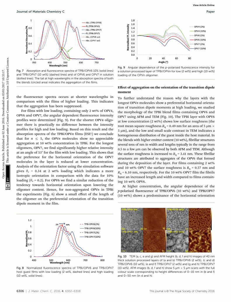
To further understand the reason why the layers with thelongest OPVn molecules show a preferential horizontal orienta-tion of transition dipole moments at high loading, we studiedthe morphology of the TPBi blend films containing OPV6 andOPV7 using AFM and TEM (Fig. 10). The TPBi layer with OPV6at low concentration (2 wt%) shows low surface roughness (theroot mean square roughness Rq = 0.49 nm for an area of 5 mm �5 mm), and the low and small scale contrast in TEM indicates ahomogeneous distribution of the guest inside the host material. Inthe blends with higher emitter content (10 wt%), fibrillar structuresseveral tens of nm in width and lengths typically in the range from0.5 to a few mm can be observed by both AFM and TEM. Althoughthe surface roughness is increased to Rq = 3.41 nm. These fibrillarstructures are attributed to aggregates of the OPV6 that formedduring the deposition of the layer. For films containing 2 wt%and 10 wt% OPV7 the surface roughness is Rq = 0.57 nm andRq = 6.10 nm, respectively. For the 10 wt% OPV7 film the fibrilshave an increased length and width compared to films contain-ing 10 wt% OPV6.
At higher concentration, the angular dependence of thep-polarised fluorescence of TPBi/OPV6 (10 wt%) and TPBi/OPV7(10 wt%) shows a predominance of the horizontal orientation
Fig. 7 Absorption and fluorescence spectra of TPBi/OPV6 10% (solid lines)and TPBi/OPV7 (10 wt%) (dashed lines) and of OPV6 and OPV7 in solution(dotted lines). The tail at high wavelengths in the absorption spectra of boththe blends (circled area) indicates the aggregation of the films.
Fig. 8 Normalized fluorescence spectra of TPBi/OPV6 and TPBi/OPV7host guest films with low loading (2 wt%, dashed lines) and high loading(10 wt%, solid lines).
Fig. 9 Angular dependence of the p-polarised fluorescence intensity fora solution processed layer of TPBi/OPVn for low (2 wt%) and high (10 wt%)loading of the OPVn oligomer.
Fig. 10 TEM (a, c, e and g) and AFM height (b, d, f and h) images of 40 nmthick solution processed layers of (a and b) TPBi/OPV6 (2 wt%), (c and d)TPBi/OPV6 (10 wt%), (e and f) TPBi/OPV7 (2 wt%) and (g and h) TPBi/OPV7(10 wt%). AFM images (b, d, f and h) show 5 mm � 5 mm scans with the fullcolour scale corresponding to height differences of 0–10 nm in (b and f)and 0–50 nm (in d and h).
Journal of Materials Chemistry C Paper
Ope
n A
cces
s A
rtic
le. P
ublis
hed
on 0
2 Ju
ne 2
016.
Dow
nloa
ded
on 0
3/01
/201
7 10
:33:
17.
Thi
s ar
ticle
is li
cens
ed u
nder
a C
reat
ive
Com
mon
s A
ttrib
utio
n 3.
0 U
npor
ted
Lic
ence
.View Article Online

This journal is©The Royal Society of Chemistry 2016 J. Mater. Chem. C, 2016, 4, 6302--6308 | 6307
of the emitting transition dipole moments in the thin film. Thespectroscopic characteristics of the fluorescence from these filmsindicate that the photons emitted originate from aggregated guestmolecules. Fibrillar aggregates of the guest molecules with a highaspect ratio can be observed directly in these films using micro-scopy. We tentatively assume that the predominantly in-planeorientation of the fibrils in the mixed film is related to the highaspect ratio. The correlation between preferred horizontal transi-tion dipole moment orientation and aggregation is further sub-stantiated by studying films with low loading and suggests that thepredominance of horizontal orientation of the transition dipolemoments may be brought about indirectly by the orientation of theaggregates in the films. A complete explanation of the horizontalalignment by a preferred orientation of the aggregates thenrequires that the transition dipole moments responsible for theemission are oriented predominantly along the long axis of theaggregate. Alternatively, the aggregates could also have a tape-likestructure with the transition dipoles oriented in the plane of thetape and the tapes orienting preferentially flat on the substrate.Currently the internal structure of the aggregates of OPV6 andOPV7 is not known in detail.29 In these possible explanations, wehave neglected any effects of photoselection of a preferred orienta-tion of the emitting dipoles. In films of high loading, rapid Forstertype energy transfer will occur, suppressing photoselection effects.For the films containing 10 wt% of OPV6 or OPV7, photoselectioneffects cannot be excluded, but are less likely to influence theresults because of the high degree of in-plane orientation of thelong aggregates.31
Conclusions
In summary, by studying the fluorescence properties of solutiondeposited thin films of a host/guest system and systematicallyvarying the length of the guest molecules we find that thepreferential horizontal orientation of the transition dipolemoments for improved outcoupling efficiency in OLED systemsmay be realized by making use of the aggregation properties ofthe emitter molecules. We note that the fluorescence efficiencyof the OPVn guest molecules is negatively affected by aggrega-tion. As such these aggregated TPBi/OPVn films with horizontallyaligned transition dipole moments are not particularly suited forOLED applications. Yet recent research on aggregation inducedfluorescence and electroluminescence has shown that highluminescence quantum yields may be achieved in aggregatingsystems of chromophoric molecules which can result in theenhanced performance of OLEDs.32–35 In this respect it is ofinterest to combine chromophores that show aggregationinduced emission and alignment of such aggregates to enhancethe performance of solution-processed OLEDs.
Acknowledgements
The authors thank Horst Greiner (Philips) and Herman Schoo(Holst Centre) for useful discussions, and Marco van der Sluis(TU/e) for the technical support with the preparation of the
measurement setup. The research of J. J. F. forms part of theresearch programme of the Dutch Polymer Institute (DPI), project#734. This research has received funding from the Ministry ofEducation, Culture and Science (Gravity program 024.001.035).
Notes and references
1 K. Kato, T. Iwasaki and T. Tsujimura, J. Photopolym. Sci.Technol., 2015, 28, 335–340.
2 W. Brutting, J. Frischeisen, T. D. Schmidt, B. J. Scholz andC. Mayr, Phys. Status Solidi A, 2013, 210, 44–65.
3 P. Liehm, C. Murawski, M. Furno, B. Lussem, K. Leo andM. C. Gather, Appl. Phys. Lett., 2012, 101, 253304.
4 M. Flammich, J. Frischeisen, D. S. Setz, D. Michaelis, B. C.Krummacher, T. D. Schmidt, W. Brutting and N. Danz, Org.Electron., 2011, 12, 1663–1668.
5 J. Frischeisen, D. Yokoyama, A. Endo, C. Adachi andW. Brutting, Org. Electron., 2011, 12, 809–817.
6 C. Mayr, M. Taneda, C. Adachi and W. Brutting, Org. Electron.,2014, 15, 3031–3037.
7 D. Yokoyama, A. Sakaguchi, M. Suzuki and C. Adachi, Appl.Phys. Lett., 2009, 95, 243303.
8 D. Yokoyama, J. Mater. Chem., 2011, 21, 19187–19202.9 D. Yokoyama, A. Sakaguchi, M. Suzuki and C. Adachi, Org.
Electron., 2009, 10, 127–137.10 D. Yokoyama, A. Sakaguchi, M. Suzuki and C. Adachi, Appl.
Phys. Lett., 2008, 93, 173302.11 D. Yokoyama, H. Sasabe, Y. Furukawa, C. Adachi and
J. Kido, Adv. Funct. Mater., 2011, 21, 1375–1382.12 A. Graf, P. Liehm, C. Murawsky, S. Hofmann, K. Leo and
M. C. Gather, J. Mater. Chem. C, 2014, 2, 10298–10304.13 M. J. Jurow, C. Mayr. T. D. Schmidt, T. Lampe, P. I. Djurovich,
W. Brutting and M. E. Thompson, Nat. Mater., 2016, 15, 85–91.14 D. McBranch, I. H. Campbell, D. L. Smith and J. P. Ferraris,
Appl. Phys. Lett., 1975, 66, 1175–1177.15 J. Sturm, S. Tasch, A. Niko, G. Leising, E. Toussaere, J. Zyss,
T. C. Kowalczyk, K. D. Singer, U. Scherf and J. Huber, ThinSolid Films, 1997, 298, 138–142.
16 M. Tammer and A. P. Monkman, Adv. Mater., 2012, 24,210–212.
17 C. M. Ramsdale and N. C. Greenham, Adv. Mater., 2012, 24,212–215.
18 L. Zhao, T. Komino, M. Inoue, J.-H. Kim, J. C. Ribierre andC. Adachi, Appl. Phys. Lett., 2015, 106, 063301.
19 M. Shibata, Y. Sakai and D. Yokoyama, J. Mater. Chem. C,2015, 3, 11187–11191.
20 Y. Sakai, M. Shibata and D. Yokoyama, Appl. Phys. Express,2015, 8, 096601.
21 E. Peeters, R. A. J. Janssen, S. C. J. Meskers and E. W. Meijer,Polym. Prepr., 1999, 40, 519–520.
22 J. Frischeisen, D. Yokoyama, C. Adachi and W. Brutting,Appl. Phys. Lett., 2010, 96, 073302.
23 B. Ruhstaller, E. Knapp, B. Perucco, N. Reinke, D. Rezzonicoand F. Muller, in Optoelectronic Devices and Properties, ed.O. Sergiyenko, InTech, Croatia, 2011, ch. 21, pp. 433–458.
Paper Journal of Materials Chemistry C
Ope
n A
cces
s A
rtic
le. P
ublis
hed
on 0
2 Ju
ne 2
016.
Dow
nloa
ded
on 0
3/01
/201
7 10
:33:
17.
Thi
s ar
ticle
is li
cens
ed u
nder
a C
reat
ive
Com
mon
s A
ttrib
utio
n 3.
0 U
npor
ted
Lic
ence
.View Article Online
6308 | J. Mater. Chem. C, 2016, 4, 6302--6308 This journal is©The Royal Society of Chemistry 2016
24 T. W. Hagler, K. Pakbaz and A. J. Heeger, Phys. Rev. B:Condens. Matter Mater. Phys., 1994, 49, 10968–10975.
25 M. Chandross, S. Mazumdar, M. Liess, P. A. Lane, Z. V.Vardeny, M. Hamaguchi and K. Yoshino, Phys. Rev. B: Condens.Matter Mater. Phys., 1997, 55, 1486–1496.
26 S. A. Mewes, J.-M. Mewes, A. Dreuw and F. Plasser, Phys.Chem. Chem. Phys., 2016, 18, 2548–2563.
27 G. Bjork, S. Machida, Y. Yamamoto and K. Igeta, Phys. Rev.A: At., Mol., Opt. Phys., 1991, 44, 669–681.
28 M. Furno, R. Meerheim, S. Hofmann, B. Lussem and K. Leo,Phys. Rev. B: Condens. Matter Mater. Phys., 2012, 85, 115205.
29 E. Peeters, A. Marcos, S. C. J. Meskers and R. A. J. Janssen,J. Chem. Phys., 2000, 112, 9445–9454.
30 F. C. Spano, Annu. Rev. Phys. Chem., 2006, 57, 217–243.31 S. C. J. Meskers, R. A. J. Janssen, J. E. M. Haverkort and
J. H. Wolter, Chem. Phys., 2000, 260, 415–439.32 Y. Hong, J. W. Y. Lam and B. Z. Tang, Chem. Soc. Rev., 2011,
40, 5361–5388.33 C.-W. Lin and C.-T. Chen, in Aggregation-Induced Emission*
Applications, ed. A. Qin and B. Z. Tang, John Wiley & Sons,Ltd, Chichester UK, 2013, 1st edn, ch. 1, pp. 1–41.
34 H. Nie, B. Chen, C. Quan, J. Zhou, H. Qiu, R. Hu, S.-J. Su,A. Qin, Z. Zhao and B. Z. Tang, Chem. – Eur. J., 2015, 21,8137–8147.
35 Y. Kubota, K. Kasatani, H. Takai, K. Funabikia andM. Matsui, Dalton Trans., 2015, 44, 3326–3341.
Journal of Materials Chemistry C Paper
Ope
n A
cces
s A
rtic
le. P
ublis
hed
on 0
2 Ju
ne 2
016.
Dow
nloa
ded
on 0
3/01
/201
7 10
:33:
17.
Thi
s ar
ticle
is li
cens
ed u
nder
a C
reat
ive
Com
mon
s A
ttrib
utio
n 3.
0 U
npor
ted
Lic
ence
.View Article Online