Transistor Sizing Bruce Jacob ENEE 359a University of ... · SLIDE 11 UNIVERSITY OF MARYLAND More...
47
ENEE 359a Lecture/s 9 Transistor Sizing Bruce Jacob University of Maryland ECE Dept. SLIDE 1 UNIVERSITY OF MARYLAND ENEE 359a Digital VLSI Design Transistor Sizing & Logical Effort Prof. Bruce Jacob [email protected] Credit where credit is due: Slides contain original artwork (© Jacob 2004) as well as material taken liberally from Irwin & Vijay’s CSE477 slides (PSU), Schmit & Strojwas’s 18-322 slides (CMU), Dally’s EE273 slides (Stanford), Wolf’s slides for Modern VLSI Design, and/or Rabaey’s slides (UCB).
Transcript of Transistor Sizing Bruce Jacob ENEE 359a University of ... · SLIDE 11 UNIVERSITY OF MARYLAND More...

ENEE 359aLecture/s 9
Transistor Sizing
Bruce Jacob
University ofMaryland
ECE Dept.
SLIDE 1
UNIVERSITY OF MARYLAND
ENEE 359a
Digital VLSI Design
Transistor Sizing& Logical Effort
Prof . Bruce Jacobblj@ece .umd.edu
Credit where credit is due:
Slides contain original artwork (© Jacob 2004) as well as material taken liberally from Irwin & Vijay’s CSE477 slides (PSU), Schmit & Strojwas’s 18-322 slides (CMU), Dally’s EE273 slides (Stanford), Wolf’s slides for
Modern VLSI Design
, and/or Rabaey’s slides (UCB).

ENEE 359aLecture/s 9
Transistor Sizing
Bruce Jacob
University ofMaryland
ECE Dept.
SLIDE 2
UNIVERSITY OF MARYLAND
Overview
•
Sizing of transistor s to balance perf ormance of single in ver ter
•
More on RC time constant, fi rst-or der appr oximation of time dela ys
•
Sizing in comple x gates, examples
•
Sizing of in ver ter c hains f or driving high capacitance loads (off-c hip wires)

ENEE 359aLecture/s 9
Transistor Sizing
Bruce Jacob
University ofMaryland
ECE Dept.
SLIDE 3
UNIVERSITY OF MARYLAND
Resistance
WOULD LIKE B ALANCED NETW ORKS:
VDD
INPUT/S OUTPUT
Pull-upNetwork
Pull-do wnNetwork
“Dual” netw orks
(pFET netw ork)
(nFET netw ork)

ENEE 359aLecture/s 9
Transistor Sizing
Bruce Jacob
University ofMaryland
ECE Dept.
SLIDE 4
UNIVERSITY OF MARYLAND
Resistance
Resistance of MOSFET :
• Increasing W decreases the resistance; allo ws more current to fl ow
Oxide capacitance [F/cm
2
]
Gate capacitance [F]
Transconductance
(units [A/V
2
])
R
n
1
µ
n
C
ox
V
GS
V
Tn
–
( )
----------------------------------------------
LW
-----
=
C
ox
ε
ox
t
ox
⁄
=
C
G
C
ox
WL
=
β
n
µ
n
C
ox
WL
-----
k
'
n
WL
-----
= =

ENEE 359aLecture/s 9
Transistor Sizing
Bruce Jacob
University ofMaryland
ECE Dept.
SLIDE 5
UNIVERSITY OF MARYLAND
Resistance
nFET vs. pFET
(µ is the carrier mobility thr ough de vice)
R
n
1
β
n
V
DD
V
Tn
–
( )
-------------------------------------=
β
n
µ
n
C
ox
WL
-----
n
=
R
p
1
β
p
V
DD
V
Tp
–
( )
----------------------------------------=
β
p
µ
p
C
ox
WL
-----
p
=
µ
n
µ
p
-----
r
=
Typicall y(2 .. 3)

ENEE 359aLecture/s 9
Transistor Sizing
Bruce Jacob
University ofMaryland
ECE Dept.
SLIDE 6
UNIVERSITY OF MARYLAND
Transistor Sizing
SIMPLE CASE: Inver ter
If (W/L)
p
= r(W/L)
n
then ß
n
= ß
p
(and R
n
= R
p
)… symmetric in ver ter
Make pFET big ger (wider) b y factor of
r
C
L
VDD
C
L
R
p
VDD
C
L
R
n
V
OUT
V
OUT
Charging: Vout rising Disc harging: Vout falling

ENEE 359aLecture/s 9
Transistor Sizing
Bruce Jacob
University ofMaryland
ECE Dept.
SLIDE 7
UNIVERSITY OF MARYLAND
Transistor Sizing
SIMPLE CASE: Inver ter
t
pLH
= ln(2) R
p
C
L
= 0.69 R
p
C
L
t
pHL
= ln(2) R
n
C
L
= 0.69 R
n
C
L
t
p
= (t
pHL
+ t
pLH
)/2 = 0.69 C
L
(R
n
+ R
p
)/2
(note: the ln(2)RC term comes fr om fi rst-or der anal ysis of simple RC cir cuit’ s respose to step input ... time f or output to reac h 50% value … more detail on this in a moment, after we discuss
capacitance
…)
C
L
VDD
C
L
R
p
VDD
C
L
R
n
V
OUT
V
OUT
Charging: Vout rising Disc harging: Vout falling

ENEE 359aLecture/s 9
Transistor Sizing
Bruce Jacob
University ofMaryland
ECE Dept.
SLIDE 8
UNIVERSITY OF MARYLAND
Wire Resistance
•
R =
ρρρρ
l/A =
ρρρρ
l/(wh) for rectangular wires(on-c hip wires & vias, PCB traces)
•
R =
ρρρρ
l/A =
ρρρρ
l/(
ππππ
r
2
) for cir cular wires(off-c hip, off-PCB)
Material Resistivity
ρρρρ
(
ΩΩΩΩ
-m)
Silver (Ag) 1.6 x 10⁻⁸
Copper (Cu) 1.7 x 10⁻⁸
Gold (Au) 2.2 x 10⁻⁸
Aluminum (Al) 2.7 x 10⁻⁸
Tungsten (W) 5.5 x 10⁻⁸
h
w
l l
r

ENEE 359aLecture/s 9
Transistor Sizing
Bruce Jacob
University ofMaryland
ECE Dept.
SLIDE 9
UNIVERSITY OF MARYLAND
Sheet Resistance
R =
ρρρρ
l/(wh) = l/w•
ρρρρ
/h for rectangular wiresSheet resistance R
sq
=
ρρρρ
/h
(h=thickness)
Material Sheet resistance R
sq
(
ΩΩΩΩ
/sq)
n, p well diffusion 1000 to 1500
n+, p+ diffusion 50 to 150
polysilicon 150 to 200
polysilicon with silicide 4 to 5
Aluminum 0.05 to 0.1

ENEE 359aLecture/s 9
Transistor Sizing
Bruce Jacob
University ofMaryland
ECE Dept.
SLIDE 10
UNIVERSITY OF MARYLAND
More on Resistance
Sheet resistance R
sq
12 squares
6 squares
= 1sq + 1sq + 0.56sq = 1sq + 1sq + 0.2sq

ENEE 359aLecture/s 9
Transistor Sizing
Bruce Jacob
University ofMaryland
ECE Dept.
SLIDE 11
UNIVERSITY OF MARYLAND
More on Resistance
(it’s not just the c hannel that counts)

ENEE 359aLecture/s 9
Transistor Sizing
Bruce Jacob
University ofMaryland
ECE Dept.
SLIDE 12
UNIVERSITY OF MARYLAND
And No w … Capacitance (C
L
)
• intrinsic MOS transistor capacitances• extrinsic MOS transistor (fanout) capacitances• wiring (inter connect) capacitance
Cw
CDB2
CDB1
CGD12
CG4
CG3
Vout2Vin
Vout
VoutVin
M2
M1
M4
M3
Vout2
CL
V
in
V
in
pdrainndrain

ENEE 359aLecture/s 9
Transistor Sizing
Bruce Jacob
University ofMaryland
ECE Dept.
SLIDE 13
UNIVERSITY OF MARYLAND
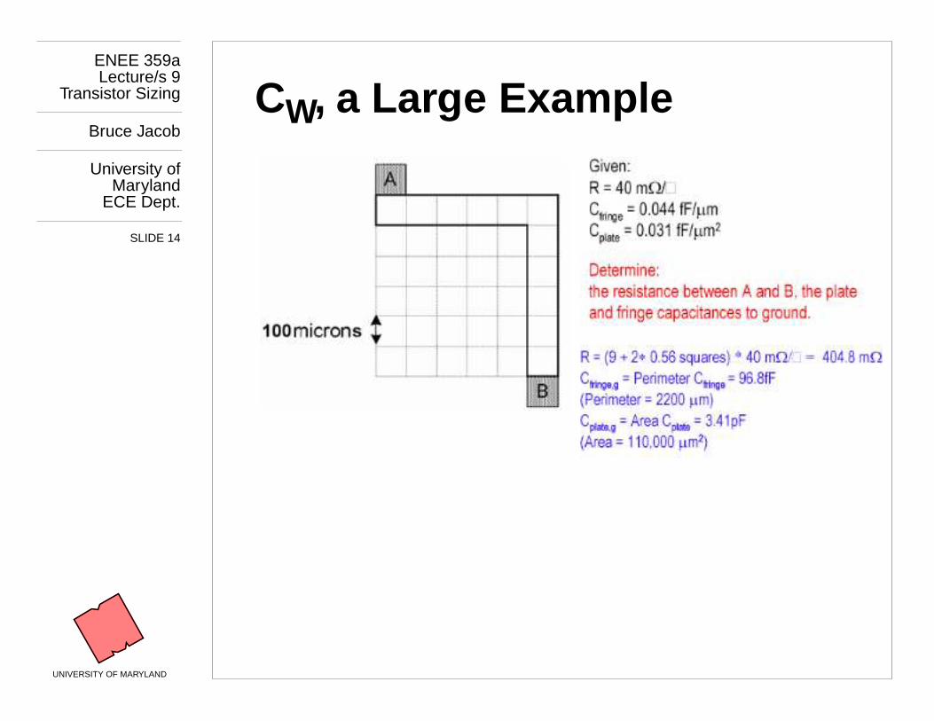
C
W
, a Large Example
ENEE 359aLecture/s 9
Transistor Sizing
Bruce Jacob
University ofMaryland
ECE Dept.
SLIDE 14
UNIVERSITY OF MARYLAND
C
W
, a Large Example

ENEE 359aLecture/s 9
Transistor Sizing
Bruce Jacob
University ofMaryland
ECE Dept.
SLIDE 15
UNIVERSITY OF MARYLAND
Two Chained In ver ters
InOut
Metal1
VDD
GND
1.2 µm=2λλλλ
1.125/0.25
0.375/0.25
PMOS
NMOS
Polysilicon
0.125 spacing
0.5 width

ENEE 359aLecture/s 9
Transistor Sizing
Bruce Jacob
University ofMaryland
ECE Dept.
SLIDE 16
UNIVERSITY OF MARYLAND
Gate-Drain Capacitance C
GD
Scales with transistor width W
InOut
Metal1
VDD
GND
1.2 µm=2λλλλ
1.125/0.25
0.375/0.25
PMOS
NMOS
Polysilicon
0.125 spacing
0.5 width
pol y
SiO
2
Overlaps

ENEE 359aLecture/s 9
Transistor Sizing
Bruce Jacob
University ofMaryland
ECE Dept.
SLIDE 17
UNIVERSITY OF MARYLAND
Diffusion Capacitance C
DB
• Drain is re verse-biased diode , non-linear C dependent on drain v olta ge (appr ox. nonlinearity with linear eqn, using K terms f or bottom plate and side walls)
InOut
Metal1
VDD
GND
1.2 µm=2λλλλ
1.125/0.25
0.375/0.25
PMOS
NMOS
Polysilicon
n-doped substrate or well
p+
Reverse-BiasedP/N Junction

ENEE 359aLecture/s 9
Transistor Sizing
Bruce Jacob
University ofMaryland
ECE Dept.
SLIDE 18
UNIVERSITY OF MARYLAND
Gate/Fan-out Capacitance C
G
Scales with both W
and
L
InOut
Metal1
VDD
GND
1.2 µm=2λλλλ
1.125/0.25
0.375/0.25
PMOS
NMOS
Polysilicon
0.125 spacing
0.5 width
pol y
SiO
2
Overlaps + P arallel Plate

ENEE 359aLecture/s 9
Transistor Sizing
Bruce Jacob
University ofMaryland
ECE Dept.
SLIDE 19
UNIVERSITY OF MARYLAND
Two Chained In ver ters: C
L
• Terms in red: under contr ol of designer• C
L
split between intrinsic and extrinsic /wire sour ces
C Term Expression Value (fF)H
→→→→
LValue (fF)L
→→→→
H
C
GD1
2 C
on
W
n
0.23 0.23
C
GD2
2 C
op
W
p
0.61 0.61
C
DB1
K
eqbpn
AD
n
C
j
+ K
eqswn
PD
n
C
jsw
0.66 0.90
C
DB2
K
eqbpp
AD
p
C
j
+ K
eqswp
PD
p
C
jsw
1.50 1.15
C
G3
2 C
on
W
n
+ C
ox
W
n
L
n
0.76 0.76
C
G4
2 C
op
W
p
+ C
ox
W
p
L
p
2.28 2.28
C
W
From extraction 0.12 0.12
C
L
Sum 6.1 6.0

ENEE 359aLecture/s 9
Transistor Sizing
Bruce Jacob
University ofMaryland
ECE Dept.
SLIDE 20
UNIVERSITY OF MARYLAND
MOSFET Switc hing
VDD
BA C
Parallel s witc hing (all s witc h at same time):
t
PLH
0.7
R
p
N
-------
•
N C
oxp
•
C
load
+
( )•
=
C
load
C
A
B
Series s witc hing (all s witc h at same time):
C
load
t
PHL
0.35
R
n
C
oxn
N
2
••
=
0.7
N R
•
n
C
load
••
+

ENEE 359aLecture/s 9
Transistor Sizing
Bruce Jacob
University ofMaryland
ECE Dept.
SLIDE 21
UNIVERSITY OF MARYLAND
RC Delay, Two Inver ters
• VDD=2.5V, 0.25mm• W/L
n
= 1.5, W/L
p
= 4.5• R
eqn
= 13 k
ΩΩΩΩ
(÷ 1.5)• R
eqp
= 31 k
ΩΩΩΩ
(÷ 4.5)
-0.5
0
0.5
1
1.5
2
2.5
3
0 0.5 1 1.5 2 2.5
Vin
Vou
t (V
)
t (sec) x 10-10
tf trtpHL tpLH
t
pHL
= 0.69 R
n
C = 36 pst
pLH
= 0.69 R
p
C = 29 ps
From SPICE simulation:t
pHL
= 39.9 ps, t
pLH
= 31.7 ps

ENEE 359aLecture/s 9
Transistor Sizing
Bruce Jacob
University ofMaryland
ECE Dept.
SLIDE 22
UNIVERSITY OF MARYLAND
Transistor Sizing I
The electrical c haracteristics of transistor s determine the s witc hing speed of a cir cuit
• Need to select the aspect ratios (W/L)
n
and (W/L)
p
of
every
FET in the cir cuit
Define
Unit Transistor
(R
1
, C
1
)
• L/W
min
-> highest resistance (needs scaling)• R
2
= R
1
÷ 2 and C
2
= 2 • C
1
• Separate nFET and pFET unit transistor s• Unit de vices are
not
restricted to individual transistor s
L L
W 2W
Sour ceDrain

ENEE 359aLecture/s 9
Transistor Sizing
Bruce Jacob
University ofMaryland
ECE Dept.
SLIDE 23
UNIVERSITY OF MARYLAND
Sizing I: Comple x Gates
Critical transistor s: those in series
• N FETs in series => scale eac h by factor of N• Ignore FETs in parallel (assume w orst case: onl y 1 on)• Ultimate goal: total resistance of net = 1 square
VDD
B
C
A
D
E
OUT
2 nets in series:scale eac h by 2x Two devices
in series: scaleeach by 2x

ENEE 359aLecture/s 9
Transistor Sizing
Bruce Jacob
University ofMaryland
ECE Dept.
SLIDE 24
UNIVERSITY OF MARYLAND
Sizing I: Comple x Gates
Critical transistor s: those in series
• N FETs in series => scale eac h by factor of N• Ignore FETs in parallel (assume w orst case: onl y 1 on)• Ultimate goal: total resistance of net = 1 square
VDD
B
C
A
D
E
OUT
2 nets in series:scale eac h by 2x Two devices
in series: scaleeach by 2x
2x14x1
4x1
2x1 2x1

ENEE 359aLecture/s 9
Transistor Sizing
Bruce Jacob
University ofMaryland
ECE Dept.
SLIDE 25
UNIVERSITY OF MARYLAND
Examples
VDD
B
C
A
D
E
D
C
EA
B
OUT

ENEE 359aLecture/s 9
Transistor Sizing
Bruce Jacob
University ofMaryland
ECE Dept.
SLIDE 26
UNIVERSITY OF MARYLAND
Examples
VDD
B
C
A
D
E
D
C
EA
B
OUT
2
2 2
2
2
4
4
2 2
2
VDD
B
C
A
D
E
DC
EA
B
OUT
2
2 2
2
2
12
12
6 6
6
Assuming Wp = 3Wn

ENEE 359aLecture/s 9
Transistor Sizing
Bruce Jacob
University ofMaryland
ECE Dept.
SLIDE 27
UNIVERSITY OF MARYLAND
Examples
VDD
BA
B
D
C
C
BA C
D A
B
OUT

ENEE 359aLecture/s 9
Transistor Sizing
Bruce Jacob
University ofMaryland
ECE Dept.
SLIDE 28
UNIVERSITY OF MARYLAND
Examples
VDD
BA
B
D
C
C
BA C
D A
B
OUT
18
18
18 6
6 6 6
3
3
32
222

ENEE 359aLecture/s 9
Transistor Sizing
Bruce Jacob
University ofMaryland
ECE Dept.
SLIDE 29
UNIVERSITY OF MARYLAND
Ways to Impr ove Gate Dela y
t
p
≈≈≈≈
(t
pHL
+ t
pLH
)
≈≈≈≈
[C
L
÷ (k’ W/L V
DD
)]
Reduce C
L
• internal diffusion capacitance of the gate itself(keep the drain diffusion as small as possib le)
• other terms: inter connect capacitance & fanout
Increase W/L ratio of the transistor
• the most po werful and eff ective perf ormance optimization tool in the hands of the designer
• watc h out f or self-loading! – when the intrinsic capacitance dominates the e xtrinsic load
Increase V
DD
• can trade-off ener gy f or perf ormance• increasing V
DD
above a cer tain le vel yields onl y ver y minimal impr ovements
• reliability concerns enf orce a fi rm upper bound on V
DD

ENEE 359aLecture/s 9
Transistor Sizing
Bruce Jacob
University ofMaryland
ECE Dept.
SLIDE 30
UNIVERSITY OF MARYLAND
Gate Delay, Revisited
t
p
≈≈≈≈
(t
pHL
+ t
pLH
)
≈≈≈≈
0.7R
ref
C
ref
(1 + C
ext
/SC
iref
)
• widening the PMOS impr oves t
pLH
(R
p
is lo wer) but degrades t
pHL
(increases intrinsic capacitance G
GD
and G
DB
)• widening the NMOS impr oves t
pHL
(R
n
is lo wer) but degrades t
pLH
(increases intrinsic capacitance G
GD
and G
DB
)
C
L
VDD
C
L
R
p
VDD
C
L
R
n
V
OUT
V
OUT
LH scenario HL Scenario

ENEE 359aLecture/s 9
Transistor Sizing
Bruce Jacob
University ofMaryland
ECE Dept.
SLIDE 31
UNIVERSITY OF MARYLAND
Gate Delay, Revisited
So far ha ve siz ed the PMOS and NMOS so that the R
eq
’s matc h (ratio between 2 & 3.5)
• symmetrical VTC• equal high-to-lo w and lo w-to-high pr opagation dela ys
If speed is the onl y concern, reduce the width of the PMOS de vice!
• widening the PMOS degrades t
pHL
due to lar ger parasitic capacitance (intrinsic capacitance)
B = (W/L
p
)/(W/L
n
)
• r = R
eqp
/R
eqn
(resistance ratio of identicall y-siz ed PMOS and NMOS)
• B
opt
≈≈≈≈
√√√√
r if wiring capacitance negligib le

ENEE 359aLecture/s 9
Transistor Sizing
Bruce Jacob
University ofMaryland
ECE Dept.
SLIDE 32
UNIVERSITY OF MARYLAND
Gate Delay, Revisited
• ß of 2.4 (R
p
/R
n
= 31 k
ΩΩΩΩ
/13 k
ΩΩΩΩ
) [what we’ ve looked at]gives symmetric response
• ß of 1.6 to 1.9 gives optimal perf ormance
3
3.5
4
4.5
5
1 2 3 4 5β = (W/Lp)/(W/Ln)
t p(s
ec)
x 10-11
tpLH
tp
tpHL

ENEE 359aLecture/s 9
Transistor Sizing
Bruce Jacob
University ofMaryland
ECE Dept.
SLIDE 33
UNIVERSITY OF MARYLAND
Inver ter Dela y
t
p
====
0.7R
ref
C
ref
(1 + C
ext
/SC
iref
)
Propagation time is function of ratio of external to internal capacitance
This ratio is called fan-out, f
Gamma term is function of tec hnology ,
γγγγ
≈≈≈≈
1
C
int
γγγγ
C
g
=
t
p
t
p0
1
C
ext
γγγγ
C
g
-----------+
=
t
p
t
p0
1
f
γγγγ
--
+
=

ENEE 359aLecture/s 9
Transistor Sizing
Bruce Jacob
University ofMaryland
ECE Dept.
SLIDE 34
UNIVERSITY OF MARYLAND
Sizing & Big Gates
Sizing f or Lar ge Capacitive Loads
Supose C
load
large (e.g. off-c hip wires)
• Scale eac h
inverter
(both FETs in the cir cuit) b y a factor A (input capacitances scale b y A)
• if input C to last in ver ter * A = C
load
(i.e., C
load
looks like N+1
th
inver ter) then we ha ve:
Input C of last in ver ter = C
in1
A
N
= C
load
• Rearranging:
A = [C
load
÷ C
in1
]
1/N
A
0
(W
p1
/W
n1
) A
2
(W
p1
/W
n1
)
A
1
(W
p1
/W
n1
) A
3
(W
p1
/W
n1
)
C
load
C
in1

ENEE 359aLecture/s 9
Transistor Sizing
Bruce Jacob
University ofMaryland
ECE Dept.
SLIDE 35
UNIVERSITY OF MARYLAND
Sizing & Big Gates
Sizing f or Lar ge Capacitive Loads
• Capacitances increase b y factor of A left to right• Resistances decrease b y factor of A left to right• Total dela y (t
pHL
+ t
pLH
):
(R
n1
+R
p1
) • (C
out1
+AC
in1
) +(R
n1
+R
p1
)/A • (AC
out1
+A
2
C
in1
) + …
= N (R
n1
+R
p1
) • (C
out1
+AC
in1
)
• Find optimal c hain length:
N
opt
= ln(C
load
÷ C
in1
)
A
0
(W
p1
/W
n1
) A
2
(W
p1
/W
n1
)
A
1
(W
p1
/W
n1
) A
3
(W
p1
/W
n1
)
C
load
C
in1

ENEE 359aLecture/s 9
Transistor Sizing
Bruce Jacob
University ofMaryland
ECE Dept.
SLIDE 36
UNIVERSITY OF MARYLAND
Sizing & Big Gates
I/O Pad: large structures are ESD diodes and in ver ter c hains (scale: pad is ~65 µm)

ENEE 359aLecture/s 9
Transistor Sizing
Bruce Jacob
University ofMaryland
ECE Dept.
SLIDE 37
UNIVERSITY OF MARYLAND
Example
Load is ~8000x that of single in ver ter’s input capacitance: find optimal solution.
C
load
= 20pFC
in
= 2.5fF
2/1

ENEE 359aLecture/s 9
Transistor Sizing
Bruce Jacob
University ofMaryland
ECE Dept.
SLIDE 38
UNIVERSITY OF MARYLAND
Example
N
opt
= ln(20pF/2.5fF) = 8.98 => 9 sta ges
Scaling factor A = (20pF/2.5fF)
1/9
= 2.7
Total dela y = (t
pHL
+ t
pLH
) = N (R
n1
+R
p1
) • (C
out1
+AC
in1
)= N (R
n1
+R
p1
) • (C
out1
+ [C
load
÷ C
in1
]
1/N
C
in1
)
(assume C
in1
= 1.5C
out1
= 2.5 fF)
= 9 • (31/9 + 13/3) • (1.85fF + 2.7 • 2.5fF)= 602 ps (0.6 ns)
C
load
= 20pF
.5/.25 1.4/.7 3.6/1.8 9.8/4.9 27/13 72/36 194/97
(sizes in micr ons)
523/262 1412/706

ENEE 359aLecture/s 9
Transistor Sizing
Bruce Jacob
University ofMaryland
ECE Dept.
SLIDE 39
UNIVERSITY OF MARYLAND
Generaliz e:
Logical Effort
Want to fi nd minim um dela y for c hains:
Main Points:
•
Path length is (ma ybe) fi xed; find scaling
•
Want constant scaling factor along path
[ this gives same
gate effort
at each stage ]
•
RC delay of a gate uses sum of internal C (its o wn C
out
) and input of ne xt gate (C
in
)
C
load
C
in

ENEE 359aLecture/s 9
Transistor Sizing
Bruce Jacob
University ofMaryland
ECE Dept.
SLIDE 40
UNIVERSITY OF MARYLAND
Definitions
g = Gate-le vel logical eff or t
= ratio of its input capacitance to that of INVER TER
A
B
r
2
r
2
g
nand
n r
+1
r
+-------------=
A B
D
C
C D
B
A
g
nor
1
nr
+1
r
+----------------=
4r
4r
4r
4r
1111

ENEE 359aLecture/s 9
Transistor Sizing
Bruce Jacob
University ofMaryland
ECE Dept.
SLIDE 41
UNIVERSITY OF MARYLAND
Definitions
Total Path Eff or t H = GFB
Optimal gate eff or t h =
G = Path Logical Eff or t
H
N
C
load
C
in
G
path
g
inv
g
nand
g
nand
g
nor
g
inv
⋅⋅⋅⋅ ⋅⋅⋅⋅ ⋅⋅⋅⋅ ⋅⋅⋅⋅
=

ENEE 359aLecture/s 9
Transistor Sizing
Bruce Jacob
University ofMaryland
ECE Dept.
SLIDE 42
UNIVERSITY OF MARYLAND
Definitions
Total Path Eff or t H = GFB
Optimal gate eff or t h =
F = Effective F an-Out of Chain
Also called
Electrical Effort
H
N
C
load
C
in
FC
load
C
in
-------------=

ENEE 359aLecture/s 9
Transistor Sizing
Bruce Jacob
University ofMaryland
ECE Dept.
SLIDE 43
UNIVERSITY OF MARYLAND
Definitions
Total Path Eff or t H = GFB
Optimal gate eff or t h =
B = Path Branc hing Eff or t
H
N
C
load
C
in
B b
node
∑
=
b
node
C
on-path
C
off-path
+
C
on-path
----------------------------------------------=

ENEE 359aLecture/s 9
Transistor Sizing
Bruce Jacob
University ofMaryland
ECE Dept.
SLIDE 44
UNIVERSITY OF MARYLAND
Definitions
Total Path Eff or t H = GFB
Optimal gate eff or t h =
Redefi ne inver ter dela y:
Total delay thr ough path:
Minim um delay thr ough path:
H
N
t
p
t
p0
1
f
γγγγ
--
+
=
t
p
t
p0
pfg
γγγγ
------+
==>
D t
p0
p
i
f
i
g
i
γγγγ
----------+
∑
=
D t
p0
p
i
∑
N H
N
γγγγ
----------------+
=

ENEE 359aLecture/s 9
Transistor Sizing
Bruce Jacob
University ofMaryland
ECE Dept.
SLIDE 45
UNIVERSITY OF MARYLAND
Definitions
Total Path Eff or t H = GFB
Optimal gate eff or t h =
Gate eff or t h
i
= g
i
f
i
Sizing s
i
for gate i in c hain:
H
N
s
i
g
1
s
1
g
i
-------------
f
j
b
j
-----
j
1=
i
1
–
∏
=

ENEE 359aLecture/s 9
Transistor Sizing
Bruce Jacob
University ofMaryland
ECE Dept.
SLIDE 46
UNIVERSITY OF MARYLAND
Anal ysis
Find minim um dela y for c hain (assume r=2):
C
in
= 20fFC
load
= 500fF
G = (1)(4/3)(4/3)(7/3)(1) = 4.15F = 500/20 = 25
B = 1 (no branc hing)
h H
N
103.75
5
2.53= = =
4/3 4/3 7/3
ENEE 359aLecture/s 9
Transistor Sizing
Bruce Jacob
University ofMaryland
ECE Dept.
SLIDE 47
UNIVERSITY OF MARYLAND
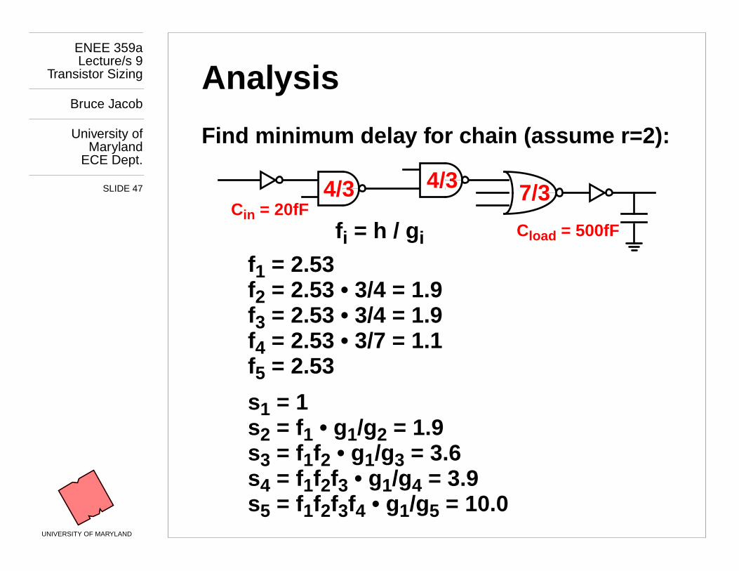
Anal ysis
Find minim um dela y for c hain (assume r=2):
C
load
= 500fFC
in
= 20fF
f
1
= 2.53
f
i
= h / g
i
s
1
= 1s
2
= f
1
• g 1 /g 2 = 1.9s
3
= f
1
f
2
• g 1 /g 3 = 3.6
s
4
= f
1
f
2
f
3
• g 1 /g 4 = 3.9
s
5
= f
1
f
2
f
3
f
4
• g 1 /g 5 = 10.0
4/3 4/3 7/3
f
2
= 2.53 • 3/4 = 1.9f
3
= 2.53 • 3/4 = 1.9
f
4
= 2.53 • 3/7 = 1.1
f
5
= 2.53