Transistor Inverter - Nuova Elva · 4 3 This makes the inverter ideal for your electronic...
13
Transistor Inverter High-performance Inverter TOSVERT™
Transcript of Transistor Inverter - Nuova Elva · 4 3 This makes the inverter ideal for your electronic...

Transistor Inverter
High-performance Inverter TOSVERT™
2
Fo
r yo
ur
Co
mm
erci
al f
acili
ties
, off
ices
an
d
fact
ori
es
• F
eatu
re: R
educ
e hi
gh-f
requ
ency
noi
se*1
, Red
uce
harm
onic
s*1
• A
pplic
atio
ns: W
ashi
ng m
achi
nes,
Tre
adm
ill, S
how
case
ref
riger
ator
s, M
edic
al
equi
pmen
t, st
age
equi
pmen
t
Fo
r m
ach
iner
y th
at r
equ
ires
sim
ple
fu
nct
ion
• F
eatu
re: E
AS
Y k
ey, 8
bas
ic p
aram
eter
s
• A
pplic
atio
ns: D
rillin
g m
achi
nes,
Han
dlin
g m
achi
nes,
Con
veyo
rs, S
emic
ondu
ctor
prod
uctio
n E
quip
men
t, C
uttin
g m
achi
nes,
Woo
dwor
king
mac
hine
ry
Fo
r m
ach
iner
y th
at r
equ
ires
hig
h t
orq
ue
and
a la
rge
cap
acit
y
•Fe
atur
e: S
tarti
ng to
rque
of 0
.3H
z-20
0%*2
, Up
to 5
00kw
for a
400
V c
lass
• A
pplic
atio
ns: C
rane
s, M
inin
g m
achi
nery
, ref
riger
ator
, Pre
sses
, Com
pres
sers
,
Cru
shin
g m
achi
ne
Hig
h-pe
rfor
man
ce In
vert
er T
OS
VE
RT
™
I nee
d th
e m
ost s
uita
ble
inve
rter
for
my
appl
icat
ion,
w
hich
has
low
noi
se, l
ow h
arm
onic
s,
min
imal
par
amet
er s
ettin
g, h
igh
torq
ue a
nd c
ontr
ol.
We
mee
t all
your
req
uire
men
ts w
ith V
F-A
S1.
It
has
outs
tand
ing
Perf
orm
ance
, inc
ludi
ng h
igh
torq
ue,
fast
res
pons
e, h
igh
accu
racy
and
exc
elle
nt e
nviro
nmen
tal
com
patib
ility
with
eas
y op
erat
ion.
The
VF-
AS
1 is
an
adva
nced
inve
rter
ev
olve
d to
sat
isfy
all
your
nee
ds
in o
ne c
ompr
ehen
sive
pro
duct
.
Flex
ible
for
you Th
is p
rodu
ct is
des
igne
d an
d m
anuf
actu
red
in fa
ctor
ies
that
ha
ve a
cqui
red
certi
ficat
ion
of
“ISO
-900
1,” t
he in
tern
atio
nal
qual
ity a
ssur
ance
sta
ndar
d.
The
fact
orie
s m
anuf
actu
ring
this
pro
duct
are
ISO
-140
01,
envi
ronm
enta
l man
agem
ent
syst
em, r
egis
tere
d fa
ctor
ies.
ISO-
9001
Cert
ificati
on A
cquir
edIS
O-1
4001
Cer
tifica
tion
Acqu
ired
For
syst
em d
evic
es th
at r
equi
res
flexi
bilit
y
• F
eatu
re:
My
func
tion,
Hig
h-pr
ecis
ion
and
high
-spe
ed
torq
ue c
ontr
ol w
ith o
r w
ithou
t sen
sors
• A
pplic
atio
ns: P
roce
ss li
nes,
Prin
ting
mac
hine
s, C
oile
rs/u
ncoi
lers
3ø20
0V/3
ø200
V
3ø40
0V/3
ø400
V
Vol
tage
Cla
ss
(inpu
t/rat
ed o
utpu
t)
App
licab
le M
otor
Out
put (
kW)
Up
to 5
.5kw
, 3-p
hase
200
V c
lass
can
be
appl
ied
to 1
-pha
se in
put p
ower
sup
ply
by u
sing
1 s
ize-
up r
atin
g
0.4
0.75
1.5
2.2
3.7
5.5
7.5
1115
18.5
2230
3745
5575
9011
013
216
020
022
028
035
540
050
0
Con
tent
s
*1 D
epen
ds
on th
e vo
ltag
e an
d c
apac
ity r
ang
e*2
Whe
n a
TOS
HIB
A s
tand
ard
3-p
hase
, 0.4
to 3
.7kw
4-p
ole
mot
or a
re d
riven
Com
patib
le w
ith th
e W
orld
’s M
ain
Sta
ndar
ds
(CE
mar
king
, UL,
CS
A, C
-tic
k)
* U
L an
d C
SA
com
plia
ncy
cond
ition
s pa
rtia
lly d
iffer
from
th
e st
anda
rd s
peci
ficat
ions
. Con
sult
us s
epar
atel
y fo
r de
tails
.
Ap
pro
val
pen
din
g
Com
ing
soon
For
you
r co
mm
erci
al fa
cilit
ies,
offi
ces
and
fact
orie
sP
3
For m
achi
nery
that
requ
ires
sim
ple
func
tion
P4
For m
achi
nery
that
requ
ires
high
torq
ue a
nd a
larg
e ca
paci
tyP
5
For
sys
tem
dev
ices
that
req
uire
s fle
xibi
lity
P6
For
mac
hine
ry th
at r
equi
res
expa
nsio
nP
7
Fun
ctio
n D
escr
iptio
nP
9
Sta
ndar
d sp
ecifi
catio
nsP
10
Ext
erna
l dim
ensi
ons
P13
Sta
ndar
d co
nnec
tion
diag
ram
sP
17
Ter
min
al fu
nctio
nsP
18
For
inve
rter
use
rsP
19
Per
iphe
ral d
evic
esP
22

43
Thi
s m
akes
the
inv
erte
r id
eal
for
your
ele
ctro
nic
appl
icat
ions
suc
h as
was
hing
mac
hine
s tr
eadm
ill,
show
case
ref
riger
ator
s fo
r st
ores
, m
edic
al
equi
pmen
t,
and
stag
e eq
uipm
ent
whe
re
atte
ntio
n m
ust
be
paid
to
perip
hera
l dev
ices
.
*1:P
hoto
s of
mac
hine
ry a
re fo
r ill
ustr
ativ
e pu
rpos
es o
nly.
Thi
s m
akes
the
inv
erte
r id
eal
for
drill
ing
mac
hine
s, h
andl
ing
mac
hine
s,
conv
eyor
s, s
emic
ondu
ctor
pro
duct
ion
equi
pmen
t, cu
tting
mac
hine
s, a
nd
woo
dwor
king
mac
hine
ry th
at r
equi
re s
impl
e fu
nctio
n.
*1:P
hoto
s of
mac
hine
ry a
re fo
r ill
ustr
ativ
e pu
rpos
es o
nly.
Inpu
t cur
rent
Conve
ntiona
l mod
els (4
00 V,
30 kW
)In
put c
urre
nt v
alue
87.
6 A
Ove
rall i
nput
pow
er fa
ctor
59%
VF-A
S1 (4
00 V
, 30
kW)
Inpu
t cur
rent
val
ue 5
8.8
AO
vera
ll inp
ut p
ower
fact
or 8
8%
Titl
eF
unct
ion
Par
amet
er s
ettin
g m
acro
func
tion
V/f
cont
rol m
ode
sele
ctio
nM
axim
um fr
eque
ncy
Acc
eler
atio
n tim
e 1
Dec
eler
atio
n tim
e 1
Mot
or o
verlo
ad p
rote
ctio
n le
vel 1
FM
term
inal
met
er a
djus
tmen
tP
aram
eter
dis
play
sel
ectio
n
For
your
com
mer
cial
fac
iliti
es, o
ffic
es a
nd f
acto
ries
•Aco
mpa
ct,
spac
e-sa
ving
new
typ
e of
DC
rea
ctor
is
built
in
to 2
00 V
cla
ss 1
1 to
45
kW a
nd 4
00 V
18.
5 to
75
kW
mod
els.
In a
dditi
on t
o re
duci
ng h
arm
onic
s, t
his
reac
tor
limits
the
in
put c
urre
nt to
110
% o
f the
rat
ed o
utpu
t cur
rent
, and
it h
as
been
des
igne
d to
be
com
patib
le w
ith p
ower
sup
ply
syst
ems
cont
aini
ng t
rans
form
ers,
mol
ded-
case
circ
uit
brea
kers
, an
d po
wer
line
s.
Add
ing
on th
e op
tiona
l DC
rea
ctor
ena
bles
com
plia
nce
with
IE
C h
arm
onic
s st
anda
rds.
Har
mo
nic
s R
edu
ctio
n, P
ow
er F
acto
r Im
pro
vem
ent
•Hig
h-fr
eque
ncy
nois
e is
dra
stic
ally
red
uced
on
mod
els
with
bu
ilt-in
noi
se f
ilter
s. B
uilt-
in n
oise
filt
ers
are
idea
l fo
r si
tes
from
com
mer
cial
fac
ilitie
s an
d of
fices
thr
ough
to
fact
orie
s w
here
atte
ntio
n m
ust b
e pa
id to
per
iphe
ral d
evic
es.
Com
pare
d w
ith f
ilter
not
int
egra
ted
mod
els,
spa
ce a
nd
wiri
ng s
avin
gs h
ave
been
ach
ieve
d by
inc
orpo
ratin
g th
e fil
ter
in t
he p
anel
. A
lso,
mod
els
with
bui
lt-in
EM
C n
oise
fil
ter
com
ply
w
ith
the
E
uro
pe
an
E
MC
D
ire
ctiv
e
as
indi
vidu
al in
vert
er u
nits
.
Hig
h-f
req
uen
cy N
ois
e R
edu
ctio
n
200V
cla
ss m
odel
s, 0
.4 to
7.5
kW: E
MI n
oise
filte
r (c
ompl
ies
with
the
Eur
opea
n E
MC
Dire
ctiv
e) b
uilt-
in s
tand
ard
200V
cla
ss m
odel
s, 1
1 to
45k
W: B
asic
noi
se fi
lter
(not
com
plie
s w
ith th
e E
urop
ean
EM
C D
irect
ive)
bui
lt-in
sta
ndar
d
400V
cla
ss m
odel
s, 0
.75
to 7
5kW
: EM
I noi
se fi
lter
(com
plie
s w
ith th
e E
urop
ean
EM
C D
irect
ive)
bui
lt-in
sta
ndar
d
400V
cla
ss m
odel
s, 9
0 to
500
kW: E
MI n
oise
filte
r (c
ompl
ies
with
the
Eur
opea
n E
MC
Dire
ctiv
e) b
uilt-
in s
tand
ard
Eur
opea
n E
MC
Dire
ctiv
e : I
EC
/EN
6180
0-3,
1st
Env
ironm
ent,
C2
or
IE
C/E
N61
800-
3, 2
nd E
nviro
nmen
t, C
3
Fo
r m
ac
hin
ery
th
at
req
uir
es
sim
ple
fu
nc
tio
n
POIN
T
•In
the
Qui
ck m
ode,
pre
ssin
g th
e E
AS
Y k
ey o
n th
e pa
nel
allo
ws
you
to o
pera
te th
e in
vert
er b
y ei
ght b
asic
par
amet
ers.
Whe
n se
tting
eac
h of
the
func
tions
, pre
ss th
e E
AS
Y k
ey to
mov
e
to t
he s
tand
ard
mod
e by
one
-tou
ch o
pera
tion.
In
this
mod
e, y
ou
can
acce
ss a
ll pa
ram
eter
s.
•Y
ou c
an c
usto
miz
e th
e Q
uick
mod
e di
spla
y, m
axim
um o
f 32
targ
et p
aram
eter
s ar
e di
spla
yed
to s
uit
your
spe
cific
set
up
requ
irem
ents
.
•You
can
als
o us
e th
e E
AS
Y k
ey a
s a
pane
l/rem
ote
key
to s
witc
h
betw
een
pane
l an
d re
mot
e op
erat
ion,
and
as
a sh
ortc
ut k
ey t
o
dire
ctly
acc
ess
any
spec
ific
setu
p or
dis
play
scr
een.
Sim
ple
Set
up
by
EA
SY
Key
Sid
e-b
y-si
de
inst
alla
tio
n•S
ide-
by-s
ide
inst
alla
tion
of in
vert
ers
is p
ossi
ble
up t
o th
e in
vert
er’s
to
tal
capa
city
. T
his
allo
ws
effe
ctiv
e ut
iliza
tion
of s
pace
ins
ide
cont
rol
pane
ls.
Hea
t si
nk c
an b
e in
stal
led
outs
ide
of t
he p
anel
as
an o
ptio
n.R
emo
vab
le c
on
tro
l ter
min
al b
oar
d•
Are
mov
able
ter
min
al b
oard
is
used
. T
his
allo
ws
you
to u
se t
he
cont
rol
wir
ing
whe
n re
plac
ing
the
inve
rter
, w
hich
als
o m
akes
m
aint
enan
ce e
asie
r.O
N/O
FF
co
ntr
ol o
f co
olin
g f
an•T
empe
ratu
re-b
ased
ON
/OF
F c
ontr
ol r
educ
es n
oise
whi
le th
e in
vert
er
is b
eing
sto
pped
, sav
es e
nerg
y an
d ex
tend
s th
e co
olin
g fa
n’s
life.
Mo
nit
ori
ng
of
serv
icea
ble
par
ts/a
larm
ou
tpu
t•
Th
e
exp
ect
ed
re
pla
cem
en
t cy
cle
o
f m
ain
ci
rcu
it ca
pa
cito
rs,
capa
cito
rs o
n co
ntro
l bo
ard,
and
coo
ling
fan
is m
onito
red,
and
an
alar
m is
out
put w
hen
the
cycl
e is
rea
ched
.
Eas
y In
stal
latio
n, E
asy
com
mis
sion
ing,
and
Eas
y m
aint
enan
ce
0.15
110
30
100 80 60 40 20
Fre
quen
cy [M
Hz]
[dB
uV]
Sid
e-by
-sid
e in
stal
latio
n
Rem
ovab
le c
ontr
ol te
rmin
al b
oard
EN
6180
0-3
1st E
nviro
nmen
t Cat
egor
y C
2
1Po
int
300
200
100
-100
-200
-3000
600
400
200
-200
-400
-600
00
200
400
600
300
200
100
-100
-200
-3000
600
400
200
-200
-400
-600
00
200
400
600
Voltage [V]
2Po
int
3Po
int
4Po
int
Current [A]
Voltage [V]
Exa
mpl
e of
gen
erat
ed n
oise
dat
a
Current [A]
Effe
ct o
f bui
lt-in
rea
ctor
Inp
ut c
urre
nt/v
olta
ge
wav
efor
mIn
put
cur
rent
/vol
tag
e w
avef
orm
Effe
ct o
f bui
lt-in
filte
r
Bui
lt-in
EM
C fi
lter
200V
-0.4
to 1
.5kW
400V
-0.7
5 to
3.7
kW
Qui
ck m
ode
(EA
SY
)
EA
SY
key

56
Thi
s m
akes
it
idea
ls f
or c
rane
s, m
inin
g m
achi
nery
, re
frig
erat
or,
pres
ses,
com
pres
sers
, cr
ushi
ng m
achi
ne a
nd o
ther
mac
hine
ry t
hat
requ
ire a
hig
h
torq
ue a
nd la
rge
capa
city
.
*1:P
hoto
s of
mac
hine
ry a
re fo
r ill
ustr
ativ
e pu
rpos
es o
nly.
Thi
s m
akes
the
inv
erte
r id
eal
for
proc
ess
lines
, pr
intin
g m
achi
nes,
coile
rs/u
ncoi
lers
.
*1:P
hoto
s of
mac
hine
ry a
re fo
r ill
ustr
ativ
e pu
rpos
es o
nly.
For m
achi
nery
that
regu
ires
high
torq
ue a
nd a
larg
e ca
paci
ty
•Mot
or c
onst
ants
req
uire
d fo
r ve
ctor
con
trol
can
be
easi
ly s
et b
y au
to-t
unin
g to
ena
ble
1:12
0 sp
eed
cont
rol.
Mor
eove
r, t
he V
F-
AS
1 al
so f
eatu
res
a ro
bust
str
uctu
re t
hat
is u
nlik
ely
to b
e in
fluen
ced
by m
otor
tem
pera
ture
.
•On
inve
rter
s pr
ovid
ed w
ith a
sen
sor,
hig
h-to
rque
ope
ratio
n of
20
0%*2
from
zer
o ve
loci
ty i
s po
ssib
le,
achi
evin
g a
spee
d co
ntro
l ran
ge o
f 1:1
000.
•Hig
h-sp
eed
resp
onse
fre
quen
cies
of
40 H
z w
ithou
t se
nsor
and
50
Hz
with
sen
sor
are
achi
eved
res
pect
ivel
y, t
o m
aint
ain
fixed
sp
eed
in r
espo
nse
to s
udde
n ch
ange
s in
load
.
•Mod
ifyin
g so
ftwar
e en
able
s hi
gh-f
requ
ency
out
put
up t
o 10
00
Hz,
whi
ch i
s id
eal
for
spin
dle
rota
tion
of w
oodw
orki
ng a
nd
met
alw
orki
ng m
achi
nery
.
*2:W
hen
a T
OS
HIB
A s
tand
ard
3-ph
ase,
0.4
to
3.7
kW 4
-pol
e m
otor
are
dr
iven
.
Exc
elle
nt
Mo
tor
Co
ntr
ol P
erfo
rman
ce
Bra
ke s
equ
ence
/lig
ht-
load
, hig
h-s
pee
d f
un
ctio
ns
• The
inve
rter
has
two
built
-in f
unct
ions
, th
e br
ake
sequ
ence
fun
ctio
n an
d lig
ht-lo
ad, h
igh-
spee
d fu
nctio
n, a
s st
anda
rd. T
he b
rake
seq
uenc
e fu
nctio
n m
easu
res
the
timin
g w
ith b
raki
ng b
y an
ext
erna
l mot
or to
ach
ieve
sm
ooth
op
erat
ion
at s
tart
and
stop
of b
raki
ng o
pera
tion.
The
ligh
t-loa
d, h
igh-
spee
d fu
nctio
n au
tom
atic
ally
inc
reas
es t
he s
peed
whe
n op
erat
ing
light
loa
ds
acco
rdin
g to
the
lifti
ng lo
ad t
o im
prov
e co
nvey
ance
effi
cien
cy.
A le
arni
ng
func
tion
for
setti
ng a
nd s
torin
g to
mem
ory
requ
ired
para
met
ers
whi
le
perfo
rmin
g ac
tual
ope
ratio
ns is
als
o pr
ovid
ed to
faci
litat
e ad
just
men
ts.
Bu
ilt-i
n t
ran
sist
or
for
dyn
amic
bra
kin
g• T
he V
F-A
S1
has
a bu
ilt-in
tra
nsis
tor
for
dyna
mic
bra
king
up
to 1
60 k
W,
whi
ch m
akes
it id
eal f
or li
fting
app
licat
ions
.
Ded
icat
ed F
un
ctio
ns
Idea
l fo
r L
ifti
ng
Ap
plic
atio
ns
Fo
r sy
ste
m d
evi
ce
s th
at
req
uir
es
fle
xib
ilit
y
•With
“M
y fu
nctio
n”,
you
can
crea
te p
rogr
ams
cont
aini
ng
up to
28
step
s. T
his
achi
eves
logi
c op
erat
ions
and
inte
rnal
da
ta o
pera
tions
. Par
amet
ers
can
also
be
set
acco
rdin
g to
an
alog
inp
ut a
nd m
inim
um-p
eak
hold
of
anal
og o
utpu
ts.
For
exa
mpl
e:(E
x.1)
(Ex.
2)
(Ex.
3)
(Ex.
4)
Inve
rter
is
auto
mat
ical
ly s
witc
hed
to c
omm
erci
al o
pera
tion
with
out t
he e
xter
nal s
eque
nce
whe
n th
e in
vert
er is
trip
ped.
A s
igna
l is
outp
ut w
hen
torq
ue r
each
es 1
20%
and
freq
uenc
y is
5 H
z.“F
orw
ard
ro
tati
on
o
pe
rati
on
,” “p
rese
t-sp
ee
d
op
era
tio
n
fre
qu
en
cy
3”
an
d “
No.
2
acc
ele
ratio
n/d
ece
lera
tion
” a
re
sim
ulta
neou
sly
turn
ed O
N b
y in
put o
n a
sing
le te
rmin
al.
The
acc
eler
atio
n/de
cele
ratio
n tim
e is
cha
nged
dyn
amic
ally
by
a v
olta
ge w
ithin
the
rang
e 0
to 1
0 V.
Cu
sto
miz
ing
by
“My
Fu
nct
ion
”
RS
-485
co
mm
un
icat
ion
s
•R
S-4
85 c
omm
unic
atio
ns i
s eq
uipp
ed a
s st
anda
rd,
and
Mod
bus-
RT
U p
roto
col
is s
uppo
rted
in
addi
tion
to T
OS
HIB
A p
roto
col.
Net
wo
rk o
pti
on
s
•U
se o
f co
mm
unic
atio
n op
tions
ena
bles
sup
port
of
Dev
iceN
et*2
, P
RO
FIB
US
and
CC
-Lin
k an
d ot
her
mai
n fie
ldbu
ses.
Dat
a tr
acin
g
•The
PC
M00
1Z c
omm
unic
atio
ns s
oftw
are
allo
ws
you
to e
dit,
mon
itor,
and
tra
ce p
aram
eter
dat
a on
a P
C,
enab
ling
easi
er
data
m
anag
emen
t fr
om
inve
rter
star
tup
thro
ugh
to m
aint
enan
ce.
*2:D
evic
eNet
is
a re
gist
ered
tra
dem
ark
of O
DV
A (
Ope
n D
evic
eNet
Ven
dor
Ass
ocia
tion)
.
Co
mm
un
icat
ion
s an
d N
etw
ork
Pro
gram
mab
leco
ntro
ller
300
Torq
ue [%
]
Sp
eed
[m
in- 1
]
200
100 0
-100
-200
-300
200
400
600
800
1000
1200
1400
1600
1800
2000
2200
2400
My
func
tion
Num
ber o
f pro
gram
ste
ps:2
8
Inte
rnal
rel
ays
:8
Inte
rnal
cou
nter
s:2
Logi
c co
mm
ands
:ST,
ST
N, A
ND
,
AN
DN
, OR
, OR
N,
SE
T, R
SE
T,
HO
LD
ON
/OFF
DE
LAY
TIM
ER
Dat
a co
mm
ands
:EQ
, NE
, GT,
GE
,
LT, L
E, A
SU
B
010
020
030
040
050
060
070
080
090
010
00Ti
me
[ms]
010
020
030
040
050
060
070
080
090
010
00Ti
me
[ms]
Mot
or s
peed
Spe
ed r
efer
ence
Load
torq
ue
Cur
rent
Mot
or s
peed
Spe
ed r
efer
ence
Load
torq
ue
Cur
rent
Exa
mpl
e of
torq
ue c
hara
cter
istic
s
Spe
ed r
espo
nse
to
refe
renc
e ch
ange
s
Set
up b
y te
achi
ng
Spe
ed r
ecov
ery
resp
onse
*1:
Whe
n a
TOS
HIB
A s
tand
ard
3-p
hase
, 20
0 V
- 2
.2 k
W 4
-pol
e m
otor
is d
riven
,(N
ote,
how
ever
, tha
t tor
que
diff
ers
acco
rdin
g to
vol
tag
e an
d c
apac
ity.)
Fast
res
pon
seFa
st r
ecov
ery
agai
nst
imp
act l
oad
5Po
int
7Po
int
8Po
int
6Po
int

7
Fo
r m
ac
hin
ery
th
at
req
uir
es
ex
pa
nsi
on
Thi
s pa
nel
is a
n 23
-cha
ract
er x
8-lin
e di
spla
y, a
nd c
an b
e us
ed
for
sim
ple
setu
p an
d m
onito
ring
by
se
lec
tio
n o
f p
ara
me
ters
usin
g th
e jo
g di
al.
The
dis
play
lan
gu
ag
e c
an
be
sw
itc
he
d
betw
een
Eng
lish
and
Japa
nese
.
(Ger
man
, Ita
lian,
Spa
nish
, an
d
Chi
nese
will
be
avai
labl
e so
on.)
Type
: RK
P00
4Z
Our
cus
tom
ers
requ
ire a
“di
spla
y th
at is
eas
ily v
isib
le f
rom
a
long
way
aw
ay.”
In r
espo
nse
to t
his
need
, w
e de
velo
ped
this
pan
el u
sing
20
mm
LE
Ds,
the
larg
est i
n its
cla
ss in
the
mar
ket,
to e
nsur
e ou
tsta
ndin
g vi
sibi
lity.
It
has
als
o be
en d
esig
ned
to b
e fit
ted
into
pan
els
for
use
as a
n ex
tens
ion
pane
l or
disp
lay.
In
add
ition
, it
can
be u
sed
as a
pa
ram
eter
cop
y an
d is
cap
able
of
stor
ing
para
met
ers
for
up t
o th
ree
mod
els.
Type
: RK
P00
2Z
Thi
s I/O
ter
min
al b
lock
can
be
adde
d on
to
enha
nce
your
sy
stem
for
extr
a co
mpa
tibili
ty w
ith a
wid
e ra
nge
of s
yste
ms:
• C
onta
ct in
puts
(4)
• C
onta
ct o
utpu
ts (
2)•
Ana
log
inpu
ts (
2)•
Ana
log
outp
uts
(2)
• P
TC
inpu
t (1)
• R
elay
out
put (
1 ci
rcui
t)•
Pul
se tr
ain
inpu
t (1)
Typ
e: E
TB
003Z
, ET
B00
4Z
Mai
n fie
ldbu
ses
are
supp
orte
d to
ena
ble
conn
ectio
n to
a
host
con
trol
ler
to a
chie
ve s
avin
gs in
spa
ce a
nd c
entr
aliz
ed
cont
rol o
f sys
tem
s.•
Dev
iceN
et*1
• P
RO
FIB
US
• C
C-L
ink
Typ
e: D
EV
002Z
Typ
e: P
DP
002Z
Typ
e: C
CL0
01Z
Ou
tsta
nd
ing
Lin
eup
of
Op
tio
ns
LC
D E
xten
sio
n P
anel
Op
tio
n
LE
D E
xten
sio
n P
anel
Op
tio
n
Expa
nded
Ter
min
al B
lock
Opt
ion
Fiel
dbus
Opt
ion
En
cod
er F
eed
bac
k O
pti
on
20m
m
*1 D
evic
eNet
is a
reg
iste
red
trad
emar
k of
OD
VA
(O
pen
Dev
iceN
et V
endo
r A
ssoc
iatio
n).
Thr
ee e
ncod
er f
eedb
ack
optio
ns a
re p
rovi
ded
to m
atch
outp
ut fo
r su
ppor
t of v
ecto
r co
ntro
l with
a s
enso
r.
• Li
ne d
river
out
put (
RS
-422
),T
ype:
VE
C00
7Z•
Ope
n co
llect
or/c
ompl
imen
tary
out
put (
12 V
),T
ype:
VE
C00
4Z•
Ope
n co
llect
or/c
ompl
imen
tary
out
put (
15 V
),T
ype:
VE
C00
5Z
9Po
int
*T
he
phot
ogra
ph
show
s a
scre
en
curr
ently
in d
evel
opm
ent.
8
Wid
e R
ang
e o
f A
pp
licat
ion
s
Saf
ety
Env
iro
nm
enta
l Co
mp
atib
ility
The
VF
-AS
1 ca
n be
use
d at
a r
atin
g up
to
an a
mbi
ent
tem
pera
ture
of
50°C
and
in e
nviro
nmen
ts u
p to
60°
C a
t a
dera
ting
curr
ent.
Am
bie
nt
tem
per
atu
re 6
0°C
88%
of m
ater
ials
use
d on
the
VF
-AS
1 ar
e re
cycl
able
, whi
ch
desi
gn m
ore
than
mee
ts o
f th
e E
urop
ean
WE
EE
(W
aste
E
lect
rical
and
Ele
ctro
nic
Equ
ipm
ent)
Dire
ctiv
e of
70%
.
Eco
Des
ign
Var
iou
s D
rive
Per
form
ance
The
PM
is d
riven
effi
cien
tly b
y a
TO
SH
IBA
orie
nted
con
trol
ar
gorit
hm to
ach
ieve
sav
ings
in e
nerg
y an
d sp
ace.
Perm
anen
t Mag
net M
otor
(PM
) Driv
e
So
ftw
are
mo
difi
catio
n i
ncr
ea
ses
ou
tpu
t u
p t
o a
hig
h
freq
uenc
y of
100
0 H
z, m
akin
g it
idea
l for
woo
dwor
king
and
m
etal
wor
king
mac
hine
ry.
Hig
h-f
req
uen
cy 1
000
Hz
Ou
tpu
t
A n
ewly
dev
elop
ed D
C b
raki
ng f
unct
ion
allo
ws
the
stop
tim
e to
a q
uart
er o
f tha
t on
conv
entio
nal m
odel
s.N
ew D
C B
raki
ng
A F
urt
her
En
han
ced
of
Fu
nct
ion
s
As
wel
l as
proc
ess-
type
PID
con
trol (
e.g.
tem
pera
ture
, pre
ssur
e,
flow
rat
e), t
he V
F-A
S1
inco
rpor
ates
spe
ed-ty
pe P
ID c
ontro
l tha
t is
com
patib
le w
ith s
peed
fee
dbac
k, f
or e
xam
ple,
in
follo
w-u
p op
erat
ion
or w
indi
ng, f
or li
ne c
ompa
tibili
ty w
ith li
ne c
ontro
l.
Mu
lti-
PID
Co
ntr
ol
Tw
o ex
tra
cont
rols
are
ach
ieve
d, t
rave
rse
cont
rol
durin
g re
win
ding
tha
t is
man
dato
ry o
n fa
bric
mac
hine
ry,
and
pow
er i
nter
rupt
ion
sync
hron
ized
con
trol
for
pre
vent
ing
thre
ad b
reak
age
whe
n a
pow
er in
terr
uptio
n oc
curs
.
• T
rave
rse
• P
ow
er in
terr
up
tio
n
syn
chro
niz
ed c
on
tro
l
Dro
opin
g di
strib
utes
the
load
of
2-sh
aft
driv
e on
con
veya
nce
mac
hine
ry,
for
exam
ple.
S
peed
ga
in
switc
hing
en
able
s ad
apta
tion
to c
hang
es in
iner
tia d
urin
g op
erat
ion.
Zer
o sp
eed
is h
old
whe
n th
e in
vert
er i
s st
oppe
d. A
nd d
wel
l co
ntro
ls
acce
lera
tion/
dece
lera
tion,
fo
r ex
ampl
e,
whe
n co
nvey
ing
heav
y lo
ads.
• D
roo
pin
g
• S
pee
d g
ain
sw
itch
ing
• Z
ero
sp
eed
lock
• D
wel
l
10Po
int

Item
Sp
ecif
icat
ion
App
licab
le M
otor
(kW
)
Type
For
m
Outp
ut C
apac
ity (k
VA) N
ote
1)
Out
put C
urre
nt (
A)
Not
e 2)
Out
put V
olta
ge
Ove
rload
Cur
rent
Rat
ing
Dyn
amic
Bra
king
Circ
uit
Dyna
mic
Brea
king
Resis
tor
Vol
tage
/freq
uenc
y
Allo
wab
le F
luct
uatio
n
Pro
tect
ive
met
hod
Coo
ling
met
hod
Col
or
Bui
lt-in
Filt
er
DC
Rea
ctor
S
tan
dar
d s
pec
ific
atio
ns
(200
V c
lass
- 0
.4 t
o 4
5 kW
, 400
V c
lass
-0.
75 t
o 7
5 kW
mo
del
)
0.4
2004
PL
1.1
3.0
(3.0
)
0.75
2007
PL
1.8
4.8
(4.5
)
1.5
2015
PL
3.0
8.0
(8.0
)
2.2
2022
PL
4.2
11
(10.
5)
3.7
2037
PL
6.7
17.5
(16.
6)
5.5
2055
PL
10 27.5
(25.
0)
7.5
2075
PL
13 33 (33)
11
2110
PM
21 54 (49)
15
2150
PM
25 66 (64)
18.5
2185
PM
29 75
22
2220
PM
34 88
30
2300
PM
46 120
37
2370
PM
55 144
45
2450
PM
67 176
Rating PowerSupply
ElectricBraking
PowerSupply
ElectricBraking
VFA
S1–
3-ph
ase,
200
to 2
40 V
(T
he m
axim
um o
utpu
t vol
tage
is th
e sa
me
as th
e in
put v
olta
ge.)
150%
–1 m
inut
e, 1
65%
–2 s
econ
ds
Bui
lt-in
Com
patib
le w
ith e
xter
nal o
ptio
ns
3-ph
ase,
200
to 2
40 V
– 5
0/60
Hz
Vol
tage
+10
% -
15%
Not
e 3)
Fre
quen
cy ±
5%
For
ced
air
cool
ing
RA
L701
6
EM
I noi
se fi
lter
Not
e 5)
Ext
erna
l opt
ion
Bas
ic n
oise
filte
r N
ote
6)
Bui
lt-in
Item
Sp
ecif
icat
ion
App
licab
le M
otor
(kW
)
Type
For
m
Outp
ut C
apac
ity (k
VA) N
ote
1)
Out
put C
urre
nt (
A)
Not
e 2)
Out
put V
olta
ge
Ove
rload
Cur
rent
Rat
ing
Dyn
amic
Bra
king
Circ
uit
Dyna
mic
Brea
king
Resis
tor
Vol
tage
/freq
uenc
y
Allo
wab
le F
luct
uatio
n
Pro
tect
ive
met
hod
Coo
ling
met
hod
Col
or
Bui
lt-in
Filt
er
DC
Rea
ctor
0.75
4007
PL
1.8
2.3
(2.3
)
1.5
4015
PL
3.1
4.1
(4.0
)
2.2
4022
PL
4.4
5.8
(5.3
)
3.7
4037
PL
8.0
10.5
(8.6
)
5.5
4055
PL
11 14.3
(13)
7.5
4075
PL
13 17.6
(17)
11
4110
PL
21 27.7
(25)
15
4150
PL
25 33 (32)
18.5
4185
PL
31 41
22
4220
PL
37 48
30
4300
PL
50 66
37
4370
PL
60 79
45
4450
PL
72 94
55
4550
PL
88 116
75
4750
PL
122
160
VFA
S1–
3-ph
ase,
380
to 4
80 V
(T
he m
axim
um o
utpu
t vol
tage
is th
e sa
me
as th
e in
put v
olta
ge.)
150%
–1 m
inut
e, 1
65%
–2 s
econ
ds
Bui
lt-in
Com
patib
le w
ith e
xter
nal o
ptio
ns
3-ph
ase,
380
to 4
80 V
– 5
0/60
Hz
Vol
tage
+10
% -
15%
Not
e 3)
Fre
quen
cy ±
5%
For
ced
air
cool
ing
RA
L701
6
EM
I noi
se fi
lter
Not
e 5)
Ext
erna
l opt
ion
Bui
lt-in
200
V c
lass
400
V c
lass
Not
e 1)
Cap
acity
is c
alcu
late
d at
220
V fo
r th
e 20
0V m
odel
s an
d at
440
V fo
r th
e 40
0V m
odel
s.N
ote
2) R
ated
out
put c
urre
nt w
hen
the
PW
M c
arrie
r fr
eque
ncy
(par
amet
er
)
is 4
kHz
or le
ss.
The
val
ues
betw
een
pare
nthe
ses
refe
r to
rat
ed o
utpu
t cur
rent
s w
hen
set t
o 12
kHz.
Not
e 3)
±10
% w
hen
the
inve
rter
is u
sed
cont
inuo
usly
(lo
ad o
f 100
%)
Not
e 4)
Inv
erte
rs,
18.5
kW o
r gr
eate
r, do
not
hav
e w
iring
por
t co
vers
. The
y ha
ve l
arge
ope
ning
s, b
ut t
here
is
no s
pace
to
bend
the
ext
erna
l ca
bles
ins
ide
the
unit.
If
they
are
fitt
ed
exte
rnal
to th
e ca
bine
t, pl
ease
use
an
optio
nal w
iring
por
t cov
er.
Not
e 5)
Com
plie
s w
ith th
e E
urop
ian
EM
C D
irect
ive
IEC
/EN
6180
0-3,
1st
env
ironm
ent,
cate
gory
C2
or IE
C/E
N61
800-
3, 2
nd e
nviro
nmen
t, ca
tego
ry C
3N
ote
6) N
ot c
ompl
ies
with
the
Eur
opea
n E
MC
Dire
ctiv
eC
ore
and
capa
citie
s w
ith e
xter
nal f
ilter
(op
tiona
l) : C
ompl
ies
with
the
Eur
opie
n E
MC
Dire
ctiv
e.
IP20
enc
lose
d ty
pe (
JEM
1030
)IP
00 e
nclo
sed
type
(JE
M10
30)
Not
e 4)
IP00
enc
lose
d ty
pe (
JEM
1030
) N
ote
4)IP
20 e
nclo
sed
type
(JE
M10
30)
910
Rating
Set
ting
Mot
or ty
pe0 1 2 3 4 5 6 7
Ove
rload
pro
tect
ion
OL
stal
l
Sta
ndar
d M
otor
VF
Mot
or
(pro
tect
)(s
tall)
(pro
tect
)(n
ot p
rote
ct)
(not
sta
ll)
(sta
ll)(n
ot s
tall)
(sta
ll)(n
ot s
tall)
(sta
ll)(n
ot s
tall)
(not
pro
tect
)(p
rote
ct)
(pro
tect
)(n
ot p
rote
ct)
(not
pro
tect
)
Eac
h “s
etup
item
” tha
t det
erm
ines
the
cont
rol c
hara
cter
istic
s of
the
inve
rter
is c
alle
d a
“par
amet
er.”
For
exa
mpl
e, to
cha
nge
the
acce
lera
tion
time,
you
cho
ose
the
acce
lera
tion
time
para
met
er (
title
d “
”)
.
To e
nter
the
Qui
ck m
ode,
pre
ss th
e E
AS
Y k
ey o
n th
e pa
nel.
In th
is m
ode,
you
ca
n se
t eig
ht o
f the
bas
ic p
aram
eter
s.
In th
is m
ode,
you
can
set
all
para
met
ers.
F
or d
etai
ls o
f par
amet
ers,
ref
er to
the
Inst
ruct
ion
Man
ual.
Ba
sic
fu
nc
tio
ns
Sta
nd
ard
sp
ec
ific
ati
on
s
Qu
ick
mo
de
(EA
SY
)
Sta
nd
ard
mo
de
B
asic
par
amet
ers
E
xten
ded
para
met
ers
Abo
ut 5
00 e
xten
ded
para
met
ers
are
avai
labl
e. F
or d
etai
ls o
n ex
tend
ed p
aram
eter
s, p
leas
e vi
sit o
ur w
eb s
ite
(htt
p:/
/ww
w.in
vert
er.
co.jp
/).
Titl
eF
unct
ion
Par
amet
er s
ettin
g m
acro
func
tion
V/f
cont
rol m
ode
sele
ctio
nM
axim
um fr
eque
ncy
Acc
eler
atio
n tim
e 1
Dec
eler
atio
n tim
e 1
Mot
or o
verlo
ad p
rote
ctio
n le
vel 1
FM
term
inal
met
er a
djus
tmen
tP
aram
eter
dis
play
sel
ectio
n
Tit
leF
un
ctio
nA
dju
stm
ent
Ran
ge
Def
ault
Freq
uenc
y of
ope
ratio
n pa
nel
0H
z
0:D
esel
ect 1
:Aut
omat
ic s
ettin
g 2:
Aut
omat
ic s
ettin
g (d
urin
g ac
cele
ratio
n on
ly)
0:D
esel
ect 1
:Aut
omat
ic to
rque
boo
st +
aut
o-tu
ning
1 2
: Sen
sorle
ss v
ecto
r co
ntro
l 1+
aut
o-tu
ning
1
0:D
isab
led
1:Fr
eque
ncy
setti
ng b
y m
eans
of v
olta
ge 2
:Fre
quen
cy s
ettin
g by
mea
ns o
f cur
rent
3:V
olta
ge/c
urre
nt s
witc
hing
from
ext
erna
l ter
min
al 4
:Fre
quen
cy s
ettin
g on
ope
ratio
n pa
nel a
nd o
pera
tion
by m
eans
of t
erm
inal
s
5: F
requ
ency
set
ting
and
oper
atio
n on
ope
ratio
n pa
nel
0:Te
rmin
al in
put e
nabl
ed 1
:Ope
ratio
n pa
nel i
nput
ena
bled
(in
clud
ing
LED
/LC
D o
ptio
n in
put)
2:O
pera
tion
pane
l RS
485
(2-w
ire) c
omm
unic
atio
n in
put 3
:Inte
rnal
RS
485
(4-w
ire)
com
mun
icat
ion
inpu
t 4:C
omm
unic
atio
n op
tion
inpu
t
1:V
I/II (
volta
ge/c
urre
nt in
put)
2:R
R/S
4 (p
oten
tiom
eter
/vol
tage
inpu
t) 3
:RX
(vo
ltage
inpu
t)
4:O
pera
tion
pane
l inp
ut e
nabl
ed (
incl
udin
g LE
D/L
CD
opt
ion
inpu
t)
5:O
pera
tion
pane
l RS
485
(2-w
ire)
com
mun
icat
ion
inpu
t 6:In
tern
al R
S48
5 (4
-wire
) co
mm
unic
atio
n in
put 7
:Com
mun
icat
ion
optio
n in
put
8:O
ptio
nal A
I1 (
diffe
rent
ial c
urre
nt in
put)
9:O
ptio
nal A
I2 (
volta
ge/c
urre
nt in
put)
10:
UP
/DO
WN
freq
uenc
y 11
:RP
pul
se in
put
12:H
igh-
spee
d pu
lse
inpu
t 13:
Bin
ary/
BC
D in
put
0:C
onst
ant t
orqu
e ch
arac
teris
tics
1:V
olta
ge d
ecre
ase
curv
e 2:
Aut
omat
ic to
rque
boo
st 3
:Sen
sorle
ss v
ecto
r co
ntro
l 1 (
spee
d)
4:S
enso
rless
vec
tor
cont
rol 2
(sp
eed/
torq
ue)
5:V
/f 5-
poin
t set
ting
6:P
M c
ontr
ol 7
:PG
feed
back
vec
tor
cont
rol 1
(sp
eed)
8:S
enso
rless
vec
tor
cont
rol 2
(sp
eed/
torq
ue)
0.0~
30.0
%
25.0
~50
0.0H
z
200V
cla
ss:5
0~33
0V
400
V c
lass
:50~
660V
30.0
~50
0.0H
z
0.0~
Hz
0.0~
Hz
0.1~
6000
sec
.
0.1~
6000
sec
.
0.0~
Hz
0.0~
Hz
~
Hz
~
Hz
~
Hz
~
Hz
~
Hz
~
Hz
~
Hz
0:F
orw
ard
run
1:F
orw
ard
run
2:F
orw
ard
run
(For
war
d/re
vers
e sw
itcha
ble
on o
pera
tion
pane
l)
3:R
ever
se r
un (
For
war
d/re
vers
e sw
itcha
ble
on o
pera
tion
pane
l)
10~
100%
0:%
, 1:A
(am
pere
)/V
(vo
lt)
0~64
(0:
Out
put f
requ
ency
, 1:F
requ
ency
com
man
d va
lue,
2:O
utpu
t cur
rent
, 3:In
put v
olta
ge, 4
:Out
put v
olta
ge, e
tc.)
- 0~64
(0:
Out
put f
requ
ency
, 1:F
requ
ency
com
man
d va
lue,
2:O
utpu
t cur
rent
, 3:In
put v
olta
ge, 4
:Out
put v
olta
ge, e
tc.)
- 1.0~
16.0
kHz
(larg
e ca
paci
ty m
odel
1.0
~8.
0kH
z)
0:D
esel
ect 1
:At a
uto-
rest
art 2
:ST
ON
/OF
F s
witc
hing
3:1
+2
4:S
tart
ing
0:D
esel
ect 1
:Pow
er r
ide-
thro
ugh
2:D
ecel
erat
ion
stop
dur
ing
pow
er fa
ilure
3:S
ynch
roni
zed
dece
lera
tion/
acce
lera
tion
(syn
chro
nize
d ac
cele
ratio
n/de
cele
ratio
n si
gnal
)
4:S
ynch
roni
zed
dece
lera
tion/
acce
lera
tion
(syn
chro
nize
d ac
cele
ratio
n/de
cele
ratio
n si
gnal
+po
wer
failu
re)
0:D
esel
ect 1
:Sel
ect (
brak
ing
resi
stan
ce o
verlo
ad d
etec
t) 2
:Sel
ect (
brak
ing
resi
stan
ce o
verlo
ad n
ot d
etec
t)
0.5~
1000
Ω0.
01~
600.
0kW
0: -
1:5
0 H
z de
faul
t set
ting
2:60
Hz
defa
ult s
ettin
g 3:
Fact
ory
defa
ult s
ettin
g 4:
Trip
cle
ared
5:C
umul
ativ
e op
erat
ion
time
clea
red
6:Ty
pe in
form
atio
n in
itial
ized
7:U
ser-
defin
ed p
aram
eter
rec
orde
d 8:
Item
7 a
bove
res
et 9
:Cum
ulat
ive
fan
oper
atio
n tim
e cl
eare
d
10:A
ccel
erat
ion/
dece
lera
tion
time
setti
ng 0
.01
sec.
~60
0.0
sec.
11:
Acc
eler
atio
n/de
cele
ratio
n tim
e se
tting
0.1
sec
.~60
00se
c.
0:S
tand
ard
setti
ng m
ode
at ti
me
of a
ctiv
atio
n of
mot
or 1
:Qui
ck m
ode
at ti
me
of a
ctiv
atio
n of
mot
or 2
:Qui
ck m
ode
only
Set
par
amet
ers
in m
ore
deta
il.
-
His
tory
func
tion
Aut
omat
ic a
ccel
erat
ion/
dece
lera
tion
Aut
omat
ic to
rque
boo
st
Aut
omat
ic fu
nctio
n se
tting
Com
man
d m
ode
sele
ctio
n
Freq
uenc
y se
tting
mod
e se
lect
ion
1
V/f
cont
rol m
ode
sele
ctio
n
Man
ual t
orqu
e bo
ost 1
Bas
e fr
eque
ncy
1
Bas
e fr
eque
ncy
volta
ge 1
Max
imum
freq
uenc
y
Upp
er li
mit
freq
uenc
y
Low
er li
mit
freq
uenc
y
Acc
eler
atio
n tim
e 1
Dec
eler
atio
n tim
e 1
RR
/S4
inpu
t poi
nt 2
freq
uenc
y
VI/I
I inp
ut p
oint
2 fr
eque
ncy
Pre
set s
peed
ope
ratio
n fr
eque
ncy
1
Pre
set s
peed
ope
ratio
n fr
eque
ncy
2
Pre
set s
peed
ope
ratio
n fr
eque
ncy
3
Pre
set s
peed
ope
ratio
n fr
eque
ncy
4
Pre
set s
peed
ope
ratio
n fr
eque
ncy
5
Pre
set s
peed
ope
ratio
n fr
eque
ncy
6
Pre
set s
peed
ope
ratio
n fr
eque
ncy
7
For
war
d ru
n/re
vers
e ru
n se
lect
ion
(ope
ratio
n pa
nel o
pera
tion)
Mot
or o
verlo
ad p
rote
ctio
n le
vel 1
Mot
or o
verlo
ad p
rote
ctio
n ch
arac
teris
tic s
elec
tion
Cur
rent
/vol
tage
uni
t sel
ectio
n
FM
term
inal
met
er s
elec
tion
FM
term
inal
met
er a
djus
tmen
t
AM
term
inal
met
er s
elec
tion
AM
term
inal
met
er a
djus
tmen
t
PW
M c
arrie
r fr
eque
ncy
Aut
o-re
star
t con
trol
sel
ectio
n
Reg
ener
ativ
e po
wer
rid
e-th
roug
h co
ntro
l
Dyn
amic
bra
king
sel
ectio
n
Dyn
amic
bra
king
res
ista
nce
Allo
wab
le c
ontin
uous
bra
king
res
ista
nce
Fact
ory
defa
ult s
ettin
g
Par
amet
er d
ispl
ay s
elec
tion
Ext
ende
d pa
ram
eter
s
Aut
omat
ic e
dit f
unct
ion
- 0 0 0 0 2 0
80.0
0.0
0.0
0.0
0.0
0.0
0.0
0.0
0.0 0 100
0 0 0 - 2 - 0 0 0 0 0 - -
Dep
ends
on
the
capa
city
WN
:60,
WP
:50.
0
Dep
ends
on
the
capa
city
WN
:60.
0, W
P:5
0.0
Dep
ends
on
the
capa
city
Dep
ends
on
the
capa
city
WN
:60.
0, W
P:5
0.0
WN
:60.
0, W
P:5
0.0
Dep
ends
on
the
capa
city
Dep
ends
on
the
capa
city
Dep
ends
on
the
capa
city
Tit
leF
un
ctio
nA
dju
stm
ent
Ran
ge
Def
ault

1112
S
tan
dar
d s
pec
ific
atio
ns
(200
V c
lass
-55
to
75
kW, 4
00 V
cla
ss -
90 t
o 5
00 k
W m
od
el)
C
om
mo
n S
pec
ific
atio
ns
200
V c
lass
400
V c
lass
Not
e 1)
Cap
acity
is c
alcu
late
d at
220
V fo
r th
e 20
0V m
odel
s an
d at
440
V fo
r th
e 40
0V m
odel
s.N
ote
2) In
dica
tes
the
valu
e w
hen
the
PW
M c
arrie
r fr
eque
ncy
(par
amet
er
)
is 2
.5 k
Hz
or le
ss.
Whe
n lo
w n
oise
(P
WM
car
rier
freq
uenc
y 8
kHz)
is r
equi
red
at 1
8.5
kW o
r m
ore,
use
an
inve
rter
of c
apac
ity o
ne r
ank
high
er th
an th
e m
otor
cap
acity
.N
ote
3) ±
10%
whe
n th
e in
vert
er is
use
d co
ntin
uous
ly (
load
of 1
00%
)N
ote
4) I
nver
ters
, 18
.5kW
or
grea
ter,
do n
ot h
ave
wiri
ng p
ort
cove
rs. T
hey
have
lar
ge o
peni
ngs,
but
the
re i
s no
spa
ce t
o be
nd t
he e
xter
nal
cabl
es i
nsid
e th
e un
it. I
f th
ey a
re f
itted
ex
tern
al to
the
cabi
net,
plea
se u
se a
n op
tiona
l wiri
ng p
ort c
over
.N
ote
5) F
or 2
00V
-55k
W, 4
00V
-90k
W o
r la
rger
mod
el, b
e su
re to
inst
all D
C r
eact
or.
How
ever
, thi
s is
unn
eces
sary
for
DC
inpu
t spe
cific
atio
ns.
Not
e 6)
Thr
ee-p
hase
380
~48
0V-5
0/60
Hz
for
4900
PC
Not
e 7)
Com
plie
s w
ith th
e E
urop
ean
EM
C D
irect
ive
IEC
/EN
6180
0-3,
2nd
env
ironm
ent,
cate
gory
C3
Item
Sp
ecif
icat
ion
App
licab
le M
otor
(kW
)
Type
For
m
Outp
ut C
apac
ity (k
VA) N
ote
1)
Out
put C
urre
nt (A
) Not
e 2)
Out
put V
olta
ge
Ove
rload
Cur
rent
Rat
ing
Dyn
amic
Bra
king
Circ
uit
Dyna
mic
Brea
king
Resis
tor
Vol
tage
/freq
uenc
y
Allo
wab
le F
luct
uatio
n
Pro
tect
ive
met
hod
Coo
ling
met
hod
Col
or
Bui
lt-in
Filt
er
DC
Rea
ctor
VFA
S1–
3-ph
ase,
200
to 2
40 V
(T
he m
axim
um o
utpu
t vol
tage
is th
e sa
me
as th
e in
put v
olta
ge.)
150%
–1 m
inut
e, 1
65%
–2 s
econ
ds
Bui
lt-in
Com
patib
le w
ith e
xter
nal o
ptio
ns
Vol
tage
+10
% –
15%
Not
e 3)
Fre
quen
cy ±
5%
IP20
enc
lose
d ty
pe (
JEM
1030
) N
ote
4)
For
ced
air
cool
ing
RA
L701
6
Ext
erna
l filt
er (
optio
nal)
Atta
ched
DC
rea
ctor
Not
e 5)
55
2550
P
84 221
75
2750
P
109
285
3-ph
ase,
200
to 2
40 V
– 5
0/60
Hz
3-ph
ase,
200
to 2
20 V
– 5
0 H
z
3-ph
ase,
200
to 2
40 V
– 6
0 H
z
Item
Sp
ecif
icat
ion
App
licab
le M
otor
(kW
)
Type
For
m
Outp
ut C
apac
ity (k
VA) N
ote
1)
Out
put C
urre
nt (A
) Not
e 2)
Out
put V
olta
ge
Ove
rload
Cur
rent
Rat
ing
Dyn
amic
Bra
king
Circ
uit
Dyna
mic
Brea
king
Resis
tor
Vol
tage
/freq
uenc
y
Allo
wab
le F
luct
uatio
n
Pro
tect
ive
met
hod
Coo
ling
met
hod
Col
or
Bui
lt-in
Filt
er
DC
Rea
ctor
90
4900
PC
136
179
110
4110
KP
C
164
215
132
4132
KP
C
197
259
160
4160
KP
C
239
314
200
4200
KP
C
295
387
220
4220
KP
C
325
427
280
4280
KP
C
419
550
355
4355
KP
C
511
671
400
4400
KP
C
578
759
500
4500
KP
C
717
941
VFA
S1–
3-ph
ase,
380
to 4
80 V
(T
he m
axim
um o
utpu
t vol
tage
is th
e sa
me
as th
e in
put v
olta
ge.)
150%
–1 m
inut
e, 1
65%
–2 s
econ
ds
Com
patib
le w
ith e
xter
nal o
ptio
ns
3-ph
ase,
380
to 4
40 V
– 5
0 H
z
3-ph
ase,
380
to 4
80 V
– 6
0 H
z
Vol
tage
+10
% –
15%
Not
e 3)
Fre
quen
cy ±
5%
IP20
enc
lose
d ty
pe (
JEM
1030
) N
ote
4)
For
ced
air
cool
ing
RA
L701
6
EM
I noi
se fi
lter
Not
e 7)
Atta
ched
DC
rea
ctor
Not
e 5)
Bui
lt-in
Com
patib
le w
ith e
xter
nal o
ptio
ns
Not
e 6)
Sta
nd
ard
sp
ec
ific
ati
on
s
Rating PowerSupply
ElectricBrakingRating Power
SupplyElectricBraking
Item
Sp
ecif
icat
ion
Control specifications Operation specifications Protective function Display functions Output signal Environments
Not
e 1:
16
cont
act i
nput
term
inal
s (o
f whi
ch 8
are
opt
ions
) ar
e pr
ogra
mm
able
con
tact
inpu
t ter
min
als,
and
they
mak
e it
poss
ible
to a
rbitr
arily
sel
ect f
rom
136
type
s of
sig
nals
.
Not
e 2:
Pro
gram
mab
le O
N/O
FF
out
put t
erm
inal
s m
ake
it po
ssib
le to
arb
itrar
ily s
elec
t fro
m 1
50 ty
pes
of s
igna
ls.
Not
e 3:
Pro
gram
mab
le a
nalo
g ou
tput
term
inal
s m
ake
it po
ssib
le to
arb
itrar
ily s
elec
t fro
m 5
5 ty
pes
of s
igna
ls.
Not
e 4:
Whe
n us
ing
inve
rter
s w
here
the
ambi
ent t
empe
ratu
re w
ill r
ise
abov
e 50
°C, r
emov
e th
e up
per
cove
r an
d op
erat
e ea
ch in
vert
er a
t a c
urre
nt lo
wer
than
the
rate
d on
e.
Not
e 5:
Thi
s fu
nctio
n pr
otec
ts in
vert
ers
from
ove
rcur
rent
due
to o
utpu
t circ
uit g
roun
d fa
ult.
4-di
git a
nd7-
segm
ent
LED
Sin
usoi
dal P
WM
con
trol
LED
Mai
n ci
rcui
t vol
tage
feed
back
con
trol
. (S
witc
habl
e be
twee
n au
tom
atic
adj
ustm
ent/f
ix/c
ontr
ol o
ff)
Set
ting
betw
een
0.01
to 5
00H
z. D
efau
lt m
ax. f
requ
ency
is s
et to
0.0
1 to
60H
z.
Max
imum
freq
uenc
y ad
just
men
t (30
to 5
00H
z)
0.01
Hz:
ope
ratio
n pa
nel i
nput
(60
Hz
base
),
0.02
Hz:
ana
log
inpu
t (60
Hz
base
, 11
bit/0
to 1
0Vdc
)
With
in±0
.2%
(25
°C±1
0°C
): an
alog
inpu
t ±0.
01%
(25
°C±1
0°C
): di
gita
l inp
ut
V/f
cons
tant
, squ
are
redu
ctio
n to
rque
con
trol
, aut
omat
ic to
rque
boo
st, v
ecto
r ca
lcul
atio
n co
ntro
l, ba
se fr
eque
ncy
adju
stm
ent 1
, 2, 3
, and
4 (
25 to
500
Hz)
, V/F
5-p
oint
arb
itrar
y se
tting
, to
rque
boo
st a
djus
tmen
t (0
to 3
0%),
sta
rt fr
eque
ncy
adju
stm
ent (
0 to
10H
z), s
top
freq
uenc
y ad
just
men
t (0
to 3
0Hz)
3kΩ
pot
entio
met
er (
poss
ible
to c
onne
ct to
1 to
10k
Ω-r
ated
pot
entio
met
er)
0 to
10V
dc (
inpu
t im
peda
nce
Zin
: 30k
Ω)
0 to
±10
Vdc
(Z
in: 2
2kΩ
)4
to 2
0mA
dc (
Zin
:242
Ω)
The
cha
ract
eris
tic c
an b
e se
t arb
itrar
ily b
y tw
o-po
int s
ettin
g. C
ompl
iant
with
6 ty
pes
of in
put;
anal
og in
put (
RR
, VI/I
I, R
X, R
X2)
, pul
se in
put a
nd b
inar
y/B
CD
inpu
t (*R
X2,
bin
ary/
BC
D
inpu
t: op
tiona
l)
3 pl
aces
. Set
ting
of ju
mp
freq
uenc
y an
d w
idth
.
Upp
er li
mit
freq
uenc
y: 0
to m
ax. f
requ
ency
, low
er li
mit
freq
uenc
y: 0
to u
pper
lim
it fr
eque
ncy
Adj
ustm
ent o
f pro
port
iona
l gai
n, in
tegr
al ti
me,
diff
eren
tial t
ime
and
dela
y fil
ter
200V
-45k
W o
r le
ss, a
djus
tabl
e be
twee
n 1.
0 to
16k
Hz
for
400V
-75k
W o
r le
ss20
0V-5
5kW
or
less
, adj
usta
ble
betw
een
1.0
to 8
kHz
for
400V
-90k
W o
r m
ore
Vol
tage
com
man
d in
put s
peci
ficat
ion:
DC
0 to
±10
V
0.01
to 6
000
sec.
Sel
ecta
ble
from
am
ong
acce
lera
tion/
dece
lera
tion.
tim
es 1
, 2, 3
and
4. A
utom
atic
acc
eler
atio
n/de
cele
ratio
n fu
nctio
n. S
-pat
tern
acc
eler
atio
n/de
cele
ratio
n 1
and
2 pa
ttern
adj
usta
ble.
Adj
ustm
ent o
f bra
king
sta
rt fr
eque
ncy
(0 to
120
Hz)
, bra
king
(0
to 1
00%
) an
d br
akin
g tim
e (0
to 1
0 se
c.).
With
em
erge
ncy
stop
bra
king
func
tion
and
mot
or s
haft
fix c
ontr
ol fu
nctio
n.
With
F-C
C c
lose
d to
forw
ard
run,
with
R-C
C c
lose
d to
rev
erse
run
, with
bot
h cl
osed
to r
ever
se r
un. W
ith S
T-C
C o
pene
d to
coa
st s
top.
Em
erge
ncy
stop
by
pane
l ope
ratio
n or
term
inal
bo
ard.
Jog
mod
e, if
sel
ecte
d, a
llow
s jo
g op
erat
ion
from
the
oper
atio
n pa
nel
Jog
run
oper
atio
n by
term
inal
boa
rd is
pos
sibl
e by
set
ting
the
para
met
ers.
By
chan
ging
the
com
bina
tion
of o
pen/
clos
e be
twee
n S
1, S
2, S
3, R
R/S
4-C
C, s
et fr
eque
ncy
+ 1
5-sp
eed
oper
atio
n.
Sel
ecta
ble
betw
een
acce
lera
tion/
dece
lera
tion
time,
torq
ue li
mit
and
V/f
by s
et fr
eque
ncy.
Cap
able
of r
esta
rtin
g af
ter
a ch
eck
of th
e m
ain
circ
uit e
lem
ents
in c
ase
the
prot
ectiv
e fu
nctio
n is
act
ivat
ed. M
ax. 1
0 tim
es s
elec
tabl
e ar
bitr
arily
. Wai
ting
time
adju
stm
ent (
0 to
10
sec.
)
The
coo
ling
fan
will
be
stop
ped
auto
mat
ical
ly to
ass
ure
long
life
whe
n un
nece
ssar
y.
Pos
sibl
e to
kee
p th
e m
otor
run
ning
usi
ng it
s re
gene
rativ
e en
ergy
in c
ase
of a
mom
enta
ry p
ower
failu
re. (
Def
ault:
OF
F)
Pos
sibl
e to
sel
ect e
ach
8 pa
ttern
s in
2 g
roup
s fr
om 1
5-sp
eed
oper
atio
n fr
eque
ncy.
Max
. 16
type
s of
ope
ratio
n po
ssib
le. T
erm
inal
boa
rd o
pera
tion/
repe
at o
pera
tion
poss
ible
.
Pos
sibl
e to
sw
itch
oper
atio
n by
com
mer
cial
pow
er s
ourc
e or
inve
rter
Incr
ease
s th
e op
erat
ing
effic
ienc
y of
the
mac
hine
by
incr
easi
ng th
e ro
tatio
nal s
peed
of t
he m
otor
whe
n it
is o
pera
ted
unde
r lig
ht lo
ad.
Whe
n tw
o or
mor
e in
vert
ers
are
used
to o
pera
te a
sin
gle
load
, thi
s fu
nctio
n pr
even
ts lo
ad fr
om c
once
ntra
ting
on o
ne in
vert
er d
ue to
unb
alan
ce.
Ext
erna
l inp
ut s
igna
l adj
ustm
ent i
s po
ssib
le to
the
oper
atio
n fr
eque
ncy
com
man
d va
lue.
Sw
itcha
ble
betw
een
stan
dard
mot
or/c
onst
ant t
orqu
e V
F m
otor
, adj
ustm
ent o
f ove
rload
pro
tect
ion
and
stal
l pre
vent
ion
leve
l.
Res
et b
y 1a
con
tact
clo
sed
(or
1b c
onta
ct o
pene
d), o
r by
ope
ratio
n pa
nel.
Or
pow
er s
ourc
e O
FF
/ON
. Thi
s fu
nctio
n is
als
o us
ed to
sav
e an
d cl
ear
trip
rec
ords
.
Sta
ll pr
even
tion,
cur
rent
lim
it, o
verc
urre
nt, o
verv
olta
ge, s
hort
circ
uit o
n th
e lo
ad s
ide,
gro
und
faul
t on
the
load
sid
e (N
ote
5), u
nder
volta
ge, m
omen
tary
pow
er fa
ilure
(15
ms
or m
ore)
, no
n-st
op c
ontr
ol a
t mom
enta
ry p
ower
failu
re, o
verlo
ad p
rote
ctio
n, a
rm o
verlo
ad a
t sta
rtin
g, o
verc
urre
nt o
n th
e lo
ad s
ide
at s
tart
ing,
ove
rcur
rent
and
ove
rload
at d
ynam
ic b
raki
ng
resi
stan
ce, f
in o
verh
eat,
emer
genc
y st
op
Key
pro
hibi
tion
sele
ctab
le b
etw
een
Sto
p ke
y on
ly, M
ode
key
only
, etc
. All
key
oper
atio
ns c
an b
e pr
ohib
ited.
Aut
omat
ic lo
ad r
educ
tion
cont
rol a
t ove
rload
ing.
(D
efau
lt: O
FF
)
Pos
sibl
e to
res
tart
the
mot
or in
coa
stin
g in
acc
orda
nce
with
its
spee
d an
d di
rect
ion.
(D
efau
lt: O
FF
)
Con
trol
sys
tem
Out
put v
olta
ge a
djus
tmen
t
Out
put f
requ
ency
ran
ge
Min
imum
set
ting
step
s of
freq
uenc
y
Freq
uenc
y ac
cura
cy
Vol
tage
/freq
uenc
y ch
arac
teris
tics
Freq
uenc
y se
tting
sig
nal
Term
inal
boa
rd b
ase
freq
uenc
y
Freq
uenc
y ju
mp
Upp
er a
nd lo
wer
lim
it fr
eque
ncie
s
PW
M c
arrie
r fr
eque
ncy
Torq
ue c
ontr
ol
DC
bra
king
For
war
d ru
n/re
vers
e ru
n N
ote
1)
Jog
run
Note
1)
Pre
set s
peed
ope
ratio
n N
ote
1)
Ret
ry
Sof
t sta
ll
Coo
ling
fan
ON
/OF
F
Ope
ratio
n pa
nel k
ey o
pera
tion
ON
/OF
F
cont
rol
Reg
ener
ativ
e po
wer
rid
e-th
roug
h co
ntro
l
Aut
o-re
star
t ope
ratio
n
Sim
plifi
ed p
atte
rn o
pera
tion
Com
mer
cial
inve
rter
sw
itchi
ng
Ligh
t-lo
ad h
igh-
spee
d op
erat
ion
Dro
opin
g fu
nctio
n
Ove
rrid
e fu
nctio
n
Pro
tect
ive
func
tion
Ele
ctro
nic
ther
mal
cha
ract
eris
tic
Res
et
Acc
eler
atio
n/de
cele
ratio
n tim
e
PID
con
trol
Inpu
t/out
put t
erm
inal
inpu
t fun
ctio
n
Sin
k/so
urce
sw
itchi
ng
Failu
re d
etec
tion
sign
alLo
w s
peed
/spe
ed re
ach
sign
al o
utpu
t Not
e 2)
Upp
er/lo
wer
lim
it fr
eque
ncy
sign
al o
utpu
t N
ote
2)
Out
put f
or fr
eque
ncy
met
er/o
utpu
t for
am
met
er
Not
e 3)
Pul
se tr
ain
freq
uenc
y ou
tput
Com
mun
icat
ion
func
tion
Ope
ratin
g en
viro
nmen
ts
Am
bien
t tem
pera
ture
Vib
ratio
n
Sto
rage
tem
pera
ture
Rel
ativ
e hu
mid
ity
Sta
ll pr
even
tion
durin
g op
erat
ion,
ove
rload
lim
it, o
verlo
ad, u
nder
volta
ge o
n po
wer
sou
rce
side
, DC
circ
uit u
nder
volta
ge, s
ettin
g er
ror,
in r
etry
, upp
er li
mit,
low
er li
mit.
Ove
rcur
rent
, ove
rvol
tage
, fin
ove
rhea
t, sh
ort c
ircui
t on
the
load
sid
e, g
roun
d fa
ult o
n th
e lo
ad s
ide,
inve
rter
ove
rload
, arm
ove
rcur
rent
at s
tart
ing,
ove
rcur
rent
on
the
load
sid
e at
sta
rtin
g,
EE
PR
OM
err
or, R
AM
err
or, R
OM
err
or, t
rans
mis
sion
err
or, (
dyna
mic
bra
king
res
isto
r ov
ercu
rren
t/ove
rload
), (
emer
genc
y st
op),
(un
derv
olta
ge),
(lo
w c
urre
nt),
(ov
erto
rque
), (
mot
or
over
load
), (
outp
ut p
hase
failu
re) T
he it
ems
in th
e pa
rent
hese
s ar
e se
lect
able
.
Ope
ratio
n fr
eque
ncy,
ope
ratio
n fr
eque
ncy
com
man
d, fo
rwar
d ru
n/re
vers
e ru
n, o
utpu
t cur
rent
, DC
vol
tage
, out
put v
olta
ge, c
ompe
nsat
ed fr
eque
ncy,
term
inal
boa
rd in
put/o
utpu
t in
form
atio
n, C
PU
ver
sion
, con
trol
EE
PR
OM
ver
sion
, pas
t trip
his
tory
, cum
ulat
ive
oper
atio
n tim
e, s
peed
feed
back
, tor
que,
torq
ue c
omm
and,
torq
ue c
urre
nt, e
xitin
g cu
rren
t, P
ID fe
edba
ck v
alue
, mot
or o
verlo
ad fa
ctor
, inv
erte
r ov
erlo
ad fa
ctor
, PB
R o
verlo
ad fa
ctor
, PV
BR
load
fact
or, i
nput
pow
er, o
utpu
t pow
er, p
eak
outp
ut c
urre
nt, p
eak
DC
vol
tage
, M
otor
cou
nter
pse
udo
PG
, pos
ition
pul
se, R
R in
put,
VI/I
I inp
ut, R
X in
put,
RX
2 in
put,
FM
out
put,
AM
out
put,
met
er a
djus
tmen
t fix
out
put,
flash
mem
ory
vers
ion,
mai
n ci
rcui
t E
EP
RO
M v
ersi
on, t
ypes
of c
onne
ctio
n op
tion,
pre
viou
s de
faul
t set
ting,
pre
viou
s au
tom
atic
con
trol
(A
U2)
Dis
play
of o
ptio
nal u
nits
oth
er th
an o
utpu
t fre
quen
cy (
mot
or s
peed
, lin
e sp
eed,
etc
), c
urre
nt a
mpe
re/%
sw
itch,
vol
tage
vol
t/% s
witc
h
Sea
rche
s au
tom
atic
ally
par
amet
ers
that
are
diff
eren
t fro
m th
e st
anda
rd d
efau
lt se
tting
par
amet
ers.
Eas
y to
find
cha
nged
par
amet
ers.
Use
r pa
ram
eter
set
tings
can
be
save
d as
def
ault
setti
ngs.
Allo
ws
to r
eset
the
para
met
ers
to th
e us
er-d
efin
ed p
aram
eter
set
tings
.
Dis
play
s m
ain
circ
uit c
apac
itor
char
ging
.
Pos
sibl
e to
sel
ect p
ositi
ve lo
gic
or n
egat
ive
logi
c w
ith p
rogr
amm
able
inpu
t/out
put t
erm
inal
func
tion
men
u. N
ote
1: N
ote
2: (
Def
ault
setti
ng: p
ositi
ve lo
gic)
Pos
sibl
e to
sw
itch
betw
een
min
us c
omm
on (
CC
) an
d pl
us c
omm
on (
P24
) fo
r co
ntro
l ter
min
al.
(Def
ault
setti
ng: m
inus
com
mon
(C
C))
1c c
onta
ct o
utpu
t (25
0Vac
-2A
-cos
Ø=
1, 2
50V
ac-1
A-c
osØ
=0.
4, 3
0Vdc
-1A
)
Ope
n co
llect
or o
utpu
t (24
Vdc
, max
. 50m
A, o
utpu
t im
peda
nce:
33Ω
)
Ope
n co
llect
or o
utpu
t (24
Vdc
, max
. 50m
A, o
utpu
t im
peda
nce:
33Ω
)
Ana
log
outp
ut. 1
mA
dc fu
ll-sc
ale
DC
am
met
er o
r 7.
7Vdc
-1m
A v
oltm
eter
Ope
n co
llect
or o
utpu
t (24
Vdc
, max
. 50m
A)
RS
-485
sta
ndar
d 2-
chan
nel e
quip
ped
(con
nect
or: m
odul
ar 8
P)C
C-L
ink,
Dev
iceN
et a
nd P
RO
FIB
US
-DP
are
opt
iona
l.
Indo
or u
se. A
ltitu
de: 3
000m
or
less
(cu
rren
t red
uctio
n ne
cess
ary
if 10
00m
or
mor
e.)
Pla
ce n
ot e
xpos
ed to
dire
ct s
unlig
ht a
nd fr
ee o
f cor
rosi
ve a
nd e
xplo
sive
gas
es.
-10
to +
60°C
(R
emov
e th
e up
per
cove
r if
40°C
or
mor
e, m
ax. 6
0°C
) N
ote
4:
-25
to +
65°C
20 to
93%
(fr
ee fr
om c
onde
nsat
ion)
5.9m
/s2 0
.6G
or
less
(10
to 5
5Hz)
(C
ompl
iant
with
JIS
C00
40)
Cau
ses
of fa
ilure
s
Free
uni
t dis
play
Ala
rms
Cha
rge
disp
lay
Use
r de
faul
t set
ting
Aut
omat
ic e
dit f
unct
ion
Mon
itorin
g fu
nctio
n

1314
Inp
ut
Volt
age
Cla
ss
200V
400V
Ap
plic
able
Mo
tor
(kW
)
Ap
pro
x. W
eig
ht
(kg
)In
vert
er T
ype
Ext
ern
alD
imen
sio
nD
raw
ing
Dim
ensi
on
s (m
m)
0.4
0.75 1.5
2.2
3.7
5.5
7.5
11 15 18.5
22 30 37 45 0.75 1.5
2.2
3.7
5.5
7.5
11 15 18.5
22 30 37 45 55 75
3 3 3 4 4 5.5 7 9 9 21 21 39 39 39 3 3 3 4 5.5
5.5 7 13 15 21 28 28 47.5
47.5
47.5
VFA
S1-
2004
PL
VFA
S1-
2007
PL
VFA
S1-
2015
PL
VFA
S1-
2022
PL
VFA
S1-
2037
PL
VFA
S1-
2055
PL
VFA
S1-
2075
PL
VFA
S1-
2110
PM
VFA
S1-
2150
PM
VFA
S1-
2185
PM
VFA
S1-
2220
PM
VFA
S1-
2300
PM
VFA
S1-
2370
PM
VFA
S1-
2450
PM
VFA
S1-
4007
PL
VFA
S1-
4015
PL
VFA
S1-
4022
PL
VFA
S1-
4037
PL
VFA
S1-
4055
PL
VFA
S1-
4075
PL
VFA
S1-
4110
PL
VFA
S1-
4150
PL
VFA
S1-
4185
PL
VFA
S1-
4220
PL
VFA
S1-
4300
PL
VFA
S1-
4370
PL
VFA
S1-
4450
PL
VFA
S1-
4550
PL
VFA
S1-
4750
PL
130
155
175
210
230
240
320
130
155
175
210
230
240
240
320
230
260
295
295
400
420
550
230
260
295
295
400
420
550
630
152
164
164
191
191
212
242
152
164
164
191
191
212
242
290
114
138
158
190
210
206
280
114
138
158
190
210
206
206
280
220
249
283
283
386
403
525
220
249
283
283
386
403
529
605
A B C D E F H A B C D E F G I
Fig
ure
GF
igu
re H
Fig
ure
I
WH
DW
1H
1
Ex
tern
al
dim
en
sio
ns
Fig
ure
AF
igu
re B
Fig
ure
CF
igu
re D
Fig
ure
EF
igu
re F
2
00 V
cla
ss -
0.4
to
45
kW, 4
00 V
cla
ss -
0.75
to
75
kW m
od
el
W1
(Ins
talla
tion
dim
ensi
on)
W
15
D
9 H
H1 (Installation dimension)
2-R
2.5
R2.5
R6
8
W1
(Ins
talla
tion
dim
ensi
on)
W
16D
9 HH1 (Installation dimension)
R3
R7
10
2-R
3
W1
(Ins
talla
tion
dim
ensi
on)
W
16
D
9 H
H1 (Installation dimension)
R3
R7
10
2-R
3
D
H
H1 (Installation dimension)
4-ø
16
W1
(Ins
talla
tion
dim
ensi
on)
W3
3
2-R
3
R3
R7.5
12
D
H
H1 (Installation dimension)
4-ø
16
W1
(Ins
talla
tion
dim
ensi
on)
W3
3
2-R
3
R3
R7.5
10
D
H
H1 (Installation dimension)
4-ø
16
W1
(Ins
talla
tion
dim
ensi
on)
W3
3
2-R
4.5
R4.5
R10
15
H
H1 (Installation dimension)
4-ø
16
W1
(Ins
talla
tion
dim
ensi
on)
W3
3D
5
2-R
4.5
R4.5
R10
15
W1
(Ins
talla
tion
dim
ensi
on)
W
2-R
2.5
R2.5
R5.5
6
15
D
9 H
H1 (Installation dimension)
W1
(Ins
talla
tion
dim
ensi
on)
W
12
D
9 H
H1 (Installation dimension)
2-R
2.5
R2.5
R5.5
7

16
Inp
ut
Volt
age
Cla
ss
Ap
plic
able
Mo
tor
(kW
)
Ap
pro
x.W
eig
ht
(kg
)In
vert
er T
ype
Dra
win
gD
imen
sio
ns
(mm
)
55 75 90 110
132
160
200
220
280
355
400
500
84 (
59)
106
(72)
84 (
60)
106
(74)
116
(80)
163
(110
)
207
(140
)20
7 (1
40)
207
(140
)
VFA
S1-
2550
P
VFA
S1-
2750
P
VFA
S1-
4900
PC
VFA
S1-
4110
KP
C
VFA
S1-
4132
KP
C
VFA
S1-
4160
KP
C
VFA
S1-
4200
KP
CV
FAS
1-42
20K
PC
VFA
S1-
4280
KP
CV
FAS
1-43
55K
PC
VFA
S1-
4400
KP
CV
FAS
1-45
00K
PC
310
350
310
350
330
430
585
920
(680
)
1022
(782
)
920
(680
)
1022
(782
)
1190
(950
)
1190
(950
)
1190
(950
)
370
370
370
370
370
370
370
250
298
250
298
285
350
540
650
758
650
758
920
920
920
320
360
320
360
340
440
595
75 72 75 72 75 75 75
150
150
150
150
150
150
150
30 30 30 30 30 30 30
J (J') K (K') J (J') K (K') L (L')
M (M')
N (N')
Fig
ure
M'
Fig
ure
M
Fig
ure
N'
Fig
ure
N
WH
DW
1H
1W
2H
2H
3H
4
200V
400V
Not
e) V
alue
s in
(
) ar
e no
t DC
rea
ctor
atta
ched
.
Com
ing
soon
W1
(Ins
talla
tion
dim
ensi
on)
H
H1 (Installation dimension)
4-ø
24
WD
7
2-R
5.7
R5.7
R12
17
WD
7(H)H2H3H4
W2
4-ø24
H1 (Installation dimension)
W1
(Ins
talla
tion
dim
ensi
on)
2-R
5.7
R5.7
R12
17
H
H1 (Installation dimension)
Bra
king
Uni
t (op
tion)
4-ø
24
W1
(Ins
talla
tion
dim
ensi
on)
W75
D7
2-R
5.7
R5.7
R12
17
(H)
H2H3H4
4-ø24
WD
775
W2
H1 (Installation dimension)
Braking Unit (option)
W1
(Ins
talla
tion
dim
ensi
on)
2-R
5.7
R5.7
R12
17
15
Fig
ure
J'
Fig
ure
J
Fig
ure
K'
Fig
ure
K
Fig
ure
L'
Fig
ure
L
Ex
tern
al
dim
en
sio
ns
2
00 V
cla
ss -
55
to 7
5 kW
, 400
V c
lass
- 9
0 to
500
kW
mo
del
W1
(Ins
talla
tion
dim
ensi
on)
WD
5H
H1 (Installation dimension)
4-ø
24
2-R
5.7
R5.7
R12
17
WW2
D5(H)
H2 H3 H4
4-ø24
H1 (Installation dimension)
W1
(Ins
talla
tion
dim
ensi
on)
2-R
5.7
R5.7
R12
17
W1
(Ins
talla
tion
dim
ensi
on)
WD
5
H
H1 (Installation dimension)
4-ø
24
2-R
5.7
R5.7
R12
15
WD
5
(H)
H2H3H4
4-ø24
W2
H1 (Installation dimension)
W1
(Ins
talla
tion
dim
ensi
on)
2-R
5.7
R5.7
R12
15
W1
(Ins
talla
tion
dim
ensi
on)
W
H
H1 (Installation dimension)
4-ø
24
D7
2-R
5.7
R5.7
R12
17
WW2
D7
(H)
H2H3H4
4-ø24
H1 (Installation dimension)
W1
(Ins
talla
tion
dim
ensi
on)
2-R
5.7
R5.7
R12
17

1817
Term
ina
l fu
nc
tio
ns
Sta
nd
ard
co
nn
ec
tio
n d
iag
ram
s
+D
C-D
C
PO
MC
MC
CB
R/L
1
S/L
2
T/L
3
RO
SO
TO
U/T
1M
otor
V/T
2
W/T
3
+S
U
FM
(OUT
1)A
MC
CA
RX
VI/I
IRR
/S4
PP
P24
/PLC
OU
T1
OU
T2
NO
CC
FLB
FLC
FLA
PA/+
PC
/-P
B
IM
400/
200
V tr
ansf
orm
er(4
00 V
cla
ss o
nly)
Con
trol
pow
er s
uppl
y ba
ckup
(op
tiona
l)
NC
con
tact
of
over
load
rel
ayS
urge
kill
er
MC
RUN
RU
N
ON
RU
NO
FF
F R ST
RE
S S1
S2
Am
met
er o
r vo
ltmet
er
Vol
tage
sig
nal:
-10
to +
10 V
Vol
tage
sig
nal:
0 to
10
Vor
cur
rent
sig
nal:
4 (0
) to
20 m
A
Ext
erna
l pot
entio
met
er(o
r vo
ltage
sig
nal a
cros
s R
R/S
4-C
CA
term
inal
s:
0 to
10
V in
put)S
3C
C
For
war
d ru
n si
gnal
Rev
erse
run
sig
nal
Sta
nd b
yR
eset
Pre
set s
peed
1P
rese
t spe
ed 2
Pre
set s
peed
3C
omm
on
RY
RY
Freq
uenc
yme
terAm
met
er
( a)
(a)
(a)
(a)(a)
0-10
V0-
20m
A0-
1mA
FM
S4
RR
RR
/S4
SW
2
SW
3
PLU
SLO
OU
T1
SW
4
SW
1
SOUR
CE
INT/
PLC
PLC
INT
SINK
Factory default settings
Mai
n ci
rcui
t pow
er s
uppl
y
200
V c
lass
:0.
4 to
55
kW3-
phas
e, 2
00 to
240
V -
50/
60 H
z75
kW
3-ph
ase,
200
to 2
40 V
- 5
0 H
z3-
phas
e, 2
00 to
240
V -
60
Hz
400
V c
lass
:0.
75 to
90
kW3-
phas
e, 3
80 to
480
V -
50/
60 H
z11
0 to
500
kW
3-ph
ase,
380
to 4
40 V
- 5
0 H
z3-
phas
e, 3
80 to
480
V -
60
Hz
*1*4
*2
*8 *9
*10
*9*9
*11
*7*5
*4
*6
From
(a)
*1:
The
inve
rter
is s
hipp
ed w
ith th
e te
rmin
als
PO
and
PA
/+ s
hort
ed w
ith a
bar
(20
0V-4
5kW
or
smal
ler,
400V
-75k
W o
r sm
alle
r).
Rem
ove
this
sho
rtin
g ba
r w
hen
inst
allin
g a
DC
rea
ctor
(D
CL)
.F
or 2
00 V
- 5
5 kW
or
mor
e, a
nd 4
00 V
- 9
0 kW
or
mor
e m
odel
s, b
e su
re to
inst
all t
he D
C r
eact
or.
*2:
The
DC
rea
ctor
is b
uilt
in fo
r m
odel
s 20
0V-1
1kW
~45
kW a
nd 4
00V
-18.
5kW
~75
kW.
*3:
The
noi
se fi
lter
is b
uilt
in fo
r m
odel
s 20
0V-4
5kW
or
smal
ler
and
all o
f 400
V.*4
: E
xter
nal b
raki
ng r
esis
tor
(opt
ion)
. Dyn
amic
bra
king
driv
e ci
rcui
t bui
lt-in
(G
TR
7) a
s st
anda
rd fo
r m
odel
s 16
0kW
or
smal
ler.
*5:
Pow
er g
ener
atio
n br
akin
g U
nit (
optio
n). W
hen
the
exte
rnal
bra
king
res
isto
r (o
ptio
nal)
is u
sed
on 2
00 k
W o
r m
ore
mod
els,
the
sepa
rate
pow
er b
raki
ng u
nit (
optio
nal)
is r
equi
red.
*6
: To
sup
ply
a D
C p
ower
, con
nect
the
cabl
es to
the
PA/+
and
PA
/- te
rmin
als.
*7:
If yo
u w
ant t
o us
e a
DC
pow
er s
uppl
y to
ope
rate
the
inve
rter
(20
0V: 1
8.5k
W o
r m
ore,
400
V: 2
2kW
or
mor
e), b
e su
re to
con
tact
you
r su
pplie
r cu
stom
er s
uppo
rt c
ente
r, be
caus
e an
in
rush
cur
rent
lim
iting
circ
uit i
s re
quire
d in
suc
h a
case
. *8
: F
or m
odel
s 20
0V-7
5kW
and
400
V-1
10kW
or
larg
er, t
hree
-pha
se p
ower
inpu
t is
nece
ssar
y to
driv
e th
e fa
n if
you
wan
t to
use
a D
C p
ower
sup
ply.
*9:
The
func
tions
ass
igne
d to
term
inal
s O
UT
1, V
I/VII
and
RR
/S4
can
be s
witc
hed
by c
hang
ing
para
met
er s
ettin
gs.
*10:
To
supp
ly c
ontr
ol p
ower
from
an
exte
rnal
pow
er s
uppl
y fo
r ba
ckin
g up
the
cont
rol p
ower
sup
plie
d fr
om th
e in
vert
er, a
n op
tiona
l con
trol
pow
er b
acku
p de
vice
(C
PS
002Z
) is
re
quire
d. In
suc
h a
case
, the
bac
kup
devi
ce is
use
d at
the
sam
e tim
e w
ith th
e in
tern
al p
ower
sup
ply
of th
e in
vert
er.
*11:
The
opt
iona
l con
trol
pow
er b
acku
p un
it ca
n be
use
d w
ith b
oth
200V
and
400
V m
odel
s.
Mai
nci
rcui
t
Con
trol
circ
uit
Noi
sefil
ter Fa
n
*3
M
ain
cir
cuit
ter
min
al
C
on
tro
l cir
cuit
ter
min
alTh
e te
rmin
al fu
nctio
n se
tting
s ca
n be
cha
nged
acc
ordi
ng to
the
appl
icat
ion.
*1: A
lthou
gh th
e C
C te
rmin
al a
nd th
e C
CA
term
inal
are
not
insu
late
d, th
ey s
houl
d be
use
d se
para
tely
, one
for
the
logi
c ci
rcui
t and
the
othe
r fo
r th
e an
alog
circ
uit.
Term
inal
Sym
bo
lTe
rmin
al F
un
ctio
n
Gro
undi
ng te
rmin
al fo
r in
vert
er c
asin
g
200V
cla
ss:
400
V c
lass
:0.
4~45
kW T
hree
-pha
se 2
00~
240V
-50/
60H
z55
kW, 7
5kW
Thr
ee-p
hase
200
~22
0V-5
0Hz
Thr
ee-p
hase
200
~24
0V-6
0Hz
Con
nect
to a
(3-
phas
e in
duct
ion)
mot
or.
Con
nect
a b
raki
ng r
esis
tor.
(For
the
optio
nal d
ynam
ic b
raki
ng u
nit,
conn
ect i
t bet
wee
n PA
/+ a
nd P
C/-
.)
Cha
nge
the
para
met
ers
,
and
if
nece
ssar
y.
200k
W m
odel
s an
d sm
alle
r ar
e no
t equ
ippe
d w
ith te
rmin
al P
B. I
f you
r ar
e us
ing
such
a m
odel
and
you
wis
h to
use
a b
raki
ng r
esis
tor,
you
will
nee
d to
pur
chas
e a
brak
ing
unit
sepa
rate
ly.
Thi
s is
a n
egat
ive
pote
ntia
l ter
min
al in
the
inte
rnal
DC
mai
n ci
rcui
t. D
C c
omm
on p
ower
can
be
inpu
t acr
oss
the
PA/+
term
inal
s (p
ositi
ve p
oten
tial).
Term
inal
s fo
r co
nnec
ting
a D
C r
eact
or (
DC
L: o
ptio
nal e
xter
nal d
evic
e). S
hort
ed b
y a
shor
t bar
whe
n sh
ippe
d fr
om th
e fa
ctor
y (2
00V
: 45k
W o
r sm
alle
r, 40
0V: 7
5kW
or
smal
ler)
. Bef
ore
inst
allin
g D
CL,
rem
ove
the
shor
t bar
.
200V
cla
ss: 7
5kW
400V
cla
ss:1
10kW
~50
0kW
Inve
rter
’s c
oolin
g po
wer
inpu
t ter
min
als.
Whe
n us
ing
a D
C p
ower
sup
ply,
con
nect
thre
e-ph
ase
pow
er c
able
s.
R/L
1, S
/L2,
T/L
3
U/T
1, V
/T2,
W/T
3
PA/+
, PB
PC
/-
PO
, PA
/+
RO
, SO
, TO
0.75
~75
kW T
hree
-pha
se 3
80~
480V
-50/
60H
z90
~50
0kW
Thr
ee-p
hase
380
~44
0V-5
0Hz
Thr
ee-p
hase
380
~48
0V-6
0Hz
F R ST
RE
S
S1
S2
S3
RR
/S4
P24
/PLC
CC
*1
PP
RR
/S4
VI/I
I
RX
FM
AM
OU
T1
OU
T2
NO
CC
A*1
+S
U
FLA
FLB
FLC
Term
inal
Sym
bol
Fu
nct
ion
Ele
ctri
cal S
pec
ific
atio
ns
Inpu
t/out
put
Lan
curr
ent
sign
al.
Cho
ose
low
cur
rent
con
tact
s to
avo
id
poor
atta
chin
g.
Sou
rce
inpu
tO
N: D
C11
V o
r m
ore
OF
F: L
ess
than
DC
5V
Inpu
t
Inpu
t
Inpu
t
Inpu
t
Inpu
t
Inpu
t
Inpu
t
Inpu
t
Out
put
Inpu
t
Out
put
Inpu
t
Inpu
t
Inpu
t
Out
put
Out
put
Out
put
Inpu
t
Out
put
Multifunction programmable contact input
Vol
tage
free
con
tact
inpu
t 24V
dc-5
mA
or
less
* S
ink/
sour
ce s
elec
tabl
e w
ith S
W1
Sin
k in
put
ON
: L
ess
than
DC
10V
OF
F :
DC
16V
or
mor
e
Not
e:
Eve
n w
hen
an e
xter
nal
pow
er s
uppl
y is
use
d (in
sin
k lo
gic
mod
e,
i.e.,
w
hen
SIN
K
(PLC
) is
se
lect
ed),
co
nnec
t th
e re
fere
nce
pote
ntia
l-sid
e (0
V s
ide)
cab
le fr
om th
e po
wer
sup
ply
to th
e C
C te
rmin
al.
10V
dc (
Per
mis
sibl
e lo
ad c
urre
nt:1
0mA
dc)
250V
ac-2
A30
Vdc
-1A
:at r
esis
tanc
e lo
ad25
0Vac
-1A
:cos
F=
0.4
10V
dc (
Inte
rnal
impe
danc
e:30
kΩ
)
10V
dc (
Inte
rnal
impe
danc
e:30
kΩ
)
4~20
mA
(In
tern
al im
peda
nce:
242Ω
)
10V
dc (
Inte
rnal
impe
danc
e:22
kΩ
)
1mA
full-
scal
e D
C a
mm
eter
or
7.5V
dc-1
mA
fu
ll-sc
ale
DC
vol
tmet
er
0-20
mA
(4-
20m
A)
Ful
l-sca
le D
C a
mm
eter
1mA
full-
scal
e D
C a
mm
eter
or
7.5V
dc-1
mA
fu
ll-sc
ale
DC
vol
tmet
er
Ope
n co
llect
or o
utpu
t24
Vdc
-50m
A
*Sin
k lo
gic/
sour
ce lo
gic
switc
habl
e
Volta
ge:2
4Vdc
±10%
Use
a p
ower
sup
ply
with
a c
urre
nt ra
ting
of 1
.1A
or
mor
e.
—
Sho
rtin
g ac
ross
F-C
C c
ause
s fo
rwar
d ro
tatio
n; o
pen
caus
es d
ecel
erat
ion
stop
. (A
cros
s S
T-C
C is
sho
rt s
tate
.)
Sho
rtin
g ac
ross
R-C
C c
ause
s re
vers
e ro
tatio
n; o
pen
caus
es d
ecel
erat
ion
stop
. (A
cros
s S
T-C
C is
sho
rt s
tate
.)
The
mot
or is
on
stan
dby
if S
T a
nd C
C a
re c
onne
cted
. It c
oast
s to
a s
top
if th
is c
onne
ctio
n is
bro
ken.
Thi
s te
rmin
al c
an b
e us
ed fo
r in
terlo
ckin
g.
Sho
rtin
g an
d th
en o
peni
ng R
ES
-CC
can
cels
the
stat
us h
eld
by a
n in
vert
er p
rote
ctiv
e fu
nctio
n. W
hen
the
inve
rter
is o
pera
ting
norm
ally
, sho
rtin
g an
d th
en o
peni
ng R
ES
-CC
pr
oduc
es n
o ef
fect
.
Sho
rtin
g ac
ross
S1-
CC
cau
ses
pres
et s
peed
ope
ratio
n.
Sho
rtin
g ac
ross
S2-
CC
cau
ses
pres
et s
peed
ope
ratio
n.
Sho
rtin
g ac
ross
S3-
CC
cau
ses
pres
et s
peed
ope
ratio
n.
SW
3: W
hen
SW
4 is
in th
e S
4 po
sitio
n, S
4 an
d C
C a
re s
hort
ed a
nd p
rese
t spe
ed o
pera
tion
is s
elec
ted.
24V
dc p
ower
out
put (
whe
n S
W1
is in
any
pos
ition
oth
er th
an P
LC)
24V
inte
rnal
out
put t
erm
inal
If S
W1
is tu
rned
to th
e P
LC p
ositi
on, t
his
term
inal
can
be
used
as
a co
mm
on te
rmin
al w
hen
an
exte
rnal
pow
er s
uppl
y is
use
d.
Dig
ital s
igna
l equ
ipot
entia
l (0V
) te
rmin
al fo
r th
e co
ntro
l circ
uit a
nd e
quip
oten
tial (
0V)
term
inal
fo
r an
opt
iona
l con
trol
pow
er s
uppl
y ba
ckup
.
Ana
log
inpu
t set
ting
pow
er o
utpu
t
SW
3: M
ultif
unct
ion
prog
ram
mab
le a
nalo
g in
put t
erm
inal
whe
n S
W4
is in
the
RR
pos
ition
. S
tand
ard
defa
ult s
ettin
g:0~
10V
dc in
put a
nd 0
~60
Hz
freq
uenc
y.
Mul
tifun
ctio
n pr
ogra
mm
able
ana
log
inpu
t.Sta
ndar
d de
faul
t set
ting:
0~
10V
dc in
put a
nd 0
~60
Hz
freq
uenc
y. T
his
term
inal
can
als
o be
use
d as
a 4
-20m
Adc
(0-
20m
Adc
) in
put t
erm
inal
, if t
he
para
met
er
set
to 1
.
Mul
tifun
ctio
n pr
ogra
mm
able
ana
log
inpu
t. S
tand
ard
defa
ult s
ettin
g:0~
±10V
dc in
put a
nd
0~±6
0Hz
freq
uenc
y.
Mul
tifun
ctio
n pr
ogra
mm
able
ana
log
outp
ut. S
tand
ard
defa
ult s
ettin
g: o
utpu
t fre
quen
cy
Con
nect
a 1
mA
dc fu
ll-sc
ale
amm
eter
or
7.5V
dc (
10V
dc)-
1mA
full-
scal
e vo
ltmet
er.
Thi
s te
rmin
al c
an a
lso
be u
sed
as a
0-2
0mA
dc (
4-20
mA
) te
rmin
al, i
f the
par
amet
er
set
to
1 an
d th
e S
W2
switc
h is
set
to O
FF.
Mul
tifun
ctio
n pr
ogra
mm
able
ana
log
outp
ut. S
tand
ard
defa
ult s
ettin
g: o
utpu
t cur
rent
Use
this
term
inal
to c
onne
ct a
1m
Adc
full-
scal
e am
met
er o
r 7.
5Vdc
(10
Vdc
)-1m
A fu
ll-sc
ale
vol
tmet
er.
Mul
tifun
ctio
n pr
ogra
mm
able
ope
n co
llect
or o
utpu
t. T
he d
efau
lt se
tting
is to
out
put a
sig
nal w
hen
outp
ut lo
w s
peed
thre
shol
d ha
s be
en r
each
ed. D
epen
ding
on
the
SW
4 se
tting
, pul
ses
are
outp
ut w
ith fr
eque
ncie
s of
1.0
0kH
z to
43.
20kH
z. S
tand
ard
defa
ult s
ettin
g:3.
84kH
z
Mul
tifun
ctio
n pr
ogra
mm
able
ope
n co
llect
or o
utpu
t. B
y de
faul
t, it
is s
et to
out
put a
sig
nal
indi
catin
g th
e co
mpl
etio
n of
acc
eler
atio
n or
dec
eler
atio
n.
Dig
ital o
utpu
t sig
nal e
quip
oten
tial (
0V) t
erm
inal
for t
he c
ontro
l circ
uit.
It is
insu
late
d fro
m th
e C
C te
rmin
al.
Ana
log
inpu
t/out
put s
igna
l equ
ipot
entia
l (0V
) te
rmin
al fo
r th
e co
ntro
l circ
uit.
DC
pow
er in
put t
erm
inal
for
oper
atin
g th
e co
ntro
l circ
uit.
Con
nect
a c
ontr
ol p
ower
bac
kup
devi
ce (
optio
nal)
betw
een
+S
U a
nd C
C.
Rel
ay c
onta
ct o
utpu
t. C
onta
ct r
atin
gU
sed
to d
etec
t the
act
ivat
ion
of th
e in
vert
er's
pro
tect
ive
func
tion.
Con
tact
acr
oss
FLA
-FLC
is
clos
ed a
nd F
LB-F
LC is
ope
ned
durin
g pr
otec
tion
func
tion
oper
atio
n.
Com
mon
to
inpu
t/out
put
24V
dc-2
00m
A
— —C
omm
on to
in
put/o
utpu
t
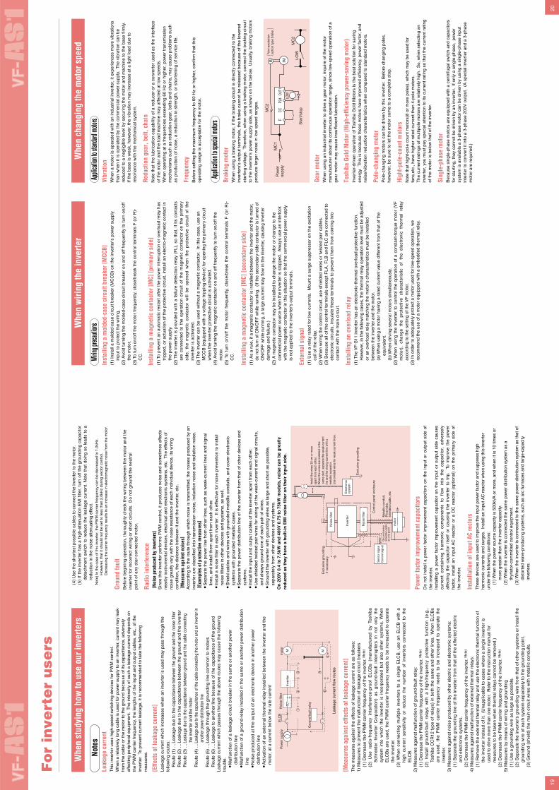
2019
Note
s
Whe
n st
udyi
ng h
ow to
use
our
inve
rters
Whe
n w
iring
the
inve
rter
Whe
n ch
angi
ng th
e m
otor
spe
ed
Wirin
g prec
autio
nsAp
plicat
ion to
stan
dard
motor
sIn
stal
ling
a m
olde
d-ca
se c
ircui
t bre
aker
[MCC
B](1
) In
stal
l a m
olde
d-ca
se c
ircui
t bre
aker
(M
CC
B)
on th
e in
vert
er's
pow
er s
uppl
y in
put t
o pr
otec
t the
wir
ing.
(2)
Avo
id tu
rnin
g th
e m
olde
d-ca
se c
ircui
t bre
aker
on
and
off f
requ
ently
to tu
rn o
n/of
f th
e m
otor
.(3
) To
turn
on/
off t
he m
otor
freq
uent
ly, c
lose
/bre
ak th
e co
ntro
l ter
min
als
F (
or R
)-C
C.
Inst
allin
g a
mag
netic
con
tact
or [M
C] [p
rimar
y si
de]
(1)
To p
reve
nt a
n au
tom
atic
res
tart
afte
r th
e po
wer
inte
rrup
tion
or o
verl
oad
rela
y ha
s tr
ippe
d, o
r ac
tuat
ion
of th
e pr
otec
tive
circ
uit,
inst
all a
n el
ectr
o-m
agne
tic c
onta
ct in
th
e po
wer
sup
ply.
(2)
The
inve
rter
is p
rovi
ded
with
a f
ailu
re d
etec
tion
rela
y (F
L),
so t
hat,
if its
con
tact
s ar
e co
nnec
ted
to t
he o
pera
tion
circ
uit
of t
he m
agne
tic c
onta
ctor
on
the
prim
ary
side
, th
e m
agne
tic c
onta
ctor
will
be
open
ed w
hen
the
prot
ectiv
e ci
rcui
t of
the
in
vert
er is
act
ivat
ed.
(3)
The
inve
rter
can
be
used
with
out a
mag
netic
con
tact
or.
In th
is c
ase,
use
an
MC
CB
(eq
uipp
ed w
ith a
vol
tage
trip
ping
dev
ice)
for
open
ing
the
prim
ary
circ
uit
whe
n th
e in
vert
er p
rote
ctiv
e ci
rcui
t is
activ
ated
.(4
) A
void
turn
ing
the
mag
netic
con
tact
or o
n an
d of
f fre
quen
tly to
turn
on/
off t
he
mot
or.
(5)
To t
urn
on/o
ff th
e m
otor
fre
quen
tly,
clos
e/br
eak
the
cont
rol
term
inal
s F
(or
R)-
CC
.
Inst
allin
g a
mag
netic
con
tact
or [M
C] [s
econ
dary
sid
e](1
) A
s a
rule
, if a
mag
netic
con
tact
or is
inst
alle
d be
twee
n th
e in
vert
er a
nd th
e m
otor
, do
not
turn
of O
N/O
FF
whi
le r
unni
ng.
(If t
he s
econ
dary
-sid
e co
ntac
tor
is tu
rned
of
ON
/OF
F w
hile
run
ning
, a la
rge
curr
ent m
ay fl
ow in
the
inve
rter
, cau
sing
inve
rter
da
mag
e an
d fa
ilure
.)(2
) A
mag
netic
con
tact
or m
ay b
e in
stal
led
to c
hang
e th
e m
otor
or
chan
ge to
the
com
mer
cial
pow
er s
ourc
e w
hen
the
inve
rter
is s
topp
ed.
Alw
ays
use
an in
terl
ock
with
the
mag
netic
con
tact
or in
this
situ
atio
n so
that
the
com
mer
cial
pow
er s
uppl
y is
not
app
lied
to th
e in
vert
er's
out
put t
erm
inal
s.
Exte
rnal
sig
nal
(1)
Use
a r
elay
rat
ed fo
r lo
w c
urre
nts.
Mou
nt a
sur
ge s
uppr
esso
r on
the
exci
tatio
n co
il of
the
rela
y.(2
) W
hen
wir
ing
the
cont
rol c
ircui
t, us
e sh
ield
ed w
ires
or tw
iste
d pa
ir ca
bles
.(3
) B
ecau
se a
ll of
the
cont
rol t
erm
inal
s ex
cept
FLA
, FLB
and
FLC
are
con
nect
ed to
el
ectr
onic
circ
uits
, ins
ulat
e th
ese
term
inal
s to
pre
vent
them
from
com
ing
into
co
ntac
t with
the
mai
n ci
rcui
t.
Inst
allin
g an
ove
rload
rela
y(1
) The
VF
-S11
inve
rter
has
an
elec
tron
ic-t
herm
al o
verl
oad
prot
ectiv
e fu
nctio
n.H
owev
er, i
n th
e fo
llow
ing
case
s, th
e th
erm
al r
elay
ope
ratio
n le
vel m
ust b
e ad
just
ed
or a
n ov
erlo
ad r
elay
mat
chin
g th
e m
otor
's c
hara
cter
istic
s m
ust b
e in
stal
led
betw
een
the
inve
rter
and
the
mot
or.
(a)
Whe
n us
ing
a m
otor
hav
ing
a ra
ted
curr
ent v
alue
diff
eren
t fro
m th
at o
f the
eq
uiva
lent
. (b
) W
hen
driv
ing
seve
ral m
otor
s si
mul
tane
ousl
y.(2
) W
hen
usin
g th
e in
vert
er t
o co
ntro
l th
e op
erat
ion
of a
con
stan
t-to
rque
mot
or (
VF
m
otor
),
chan
ge
the
prot
ectiv
e ch
arac
teri
stic
of
th
e el
ectr
onic
th
erm
al
rela
y ac
cord
ing
to th
e se
tting
of t
he V
F m
otor
.(3
) In
ord
er to
ade
quat
ely
prot
ect a
mot
or u
sed
for
low
-spe
ed o
pera
tion,
we
reco
mm
end
the
use
of a
mot
or e
quip
ped
with
a e
mbe
dded
ther
mal
rel
ay.
Vibr
atio
nW
hen
a m
otor
is o
pera
ted
with
an
indu
stri
al in
vert
er, i
t exp
erie
nces
mor
e vi
brat
ions
th
an w
hen
it is
ope
rate
d by
the
com
mer
cial
pow
er s
uppl
y. T
he v
ibra
tion
can
be
redu
ced
to a
neg
ligib
le le
vel b
y se
curi
ng th
e m
otor
and
mac
hine
to th
e ba
se fi
rmly
.If
the
base
is w
eak,
how
ever
, the
vib
ratio
n m
ay in
crea
se a
t a li
ght l
oad
due
to
reso
nanc
e w
ith th
e m
echa
nica
l sys
tem
.
Redu
ctio
n ge
ar, b
elt,
chai
nN
ote
that
the
lubr
icat
ion
capa
bilit
y of
a r
educ
er o
r a
conv
erte
r us
ed a
s th
e in
terf
ace
of th
e m
otor
and
the
load
mac
hine
may
affe
cted
at l
ow s
peed
s.W
hen
oper
atin
g at
a fr
eque
ncie
s ex
ceed
ing
60 H
z or
hig
her,
pow
er tr
ansm
issi
on
mec
hani
sms
such
as
redu
ctio
n ge
ar, b
elts
and
cha
ins,
may
cau
se p
robl
ems
such
as
pro
duct
ion
of n
oise
, a r
educ
tion
in s
tren
gth,
or
shor
teni
ng o
f ser
vice
life
.
Freq
uenc
yB
efor
e se
tting
the
max
imum
freq
uenc
y to
60
Hz
or h
ighe
r, c
onfir
m th
at th
is
oper
atin
g ra
nge
is a
ccep
tabl
e fo
r th
e m
otor
.
Appli
cation
to sp
ecial
motor
sBr
akin
g m
otor
Whe
n us
ing
a br
akin
g m
otor
, if t
he b
raki
ng c
ircui
t is
dire
ctly
con
nect
ed to
the
inve
rter
s's
outp
ut te
rmin
als,
the
brak
e ca
nnot
be
rele
ased
bec
ause
of t
he lo
wer
ed
star
ting
volta
ge.
The
refo
re, w
hen
usin
g a
brak
ing
mot
or, c
onne
ct th
e br
akin
g ci
rcui
t to
the
inve
rter
's p
ower
sup
ply
side
, as
show
n on
the
belo
w.
Usu
ally
, bra
king
mot
ors
prod
uce
larg
er n
oise
in lo
w s
peed
ran
ges.
Gear
mot
orW
hen
usin
g an
indu
stri
al in
vert
er to
dri
ve a
gea
r m
otor
, inq
uire
of t
he m
otor
m
anuf
actu
rer
abou
t its
con
tinuo
us o
pera
tion
rang
e, s
ince
low
-spe
ed o
pera
tion
of a
ge
ar m
otor
may
cau
se in
suffi
cien
t lub
rica
tion.
Tosh
iba
Gold
Mot
or (H
igh-
effic
ienc
y po
wer
-sav
ing
mot
or)
Inve
rter
-dri
ven
oper
atio
n of
Tos
hiba
Gol
d M
otor
s is
the
best
sol
utio
n fo
r sa
ving
en
ergy
. T
his
is b
ecau
se th
ese
mot
ors
have
impr
oved
effi
cien
cy, p
ower
fact
or, a
nd
nois
e/vi
brat
ion
redu
ctio
n ch
arac
teri
stic
s w
hen
com
pare
d to
sta
ndar
d m
otor
s.
Pole
-cha
ngin
g m
otor
Pol
e-ch
angi
ng m
otor
s ca
n be
dri
ven
by th
is in
vert
er.
Bef
ore
chan
ging
pol
es,
how
ever
, be
sure
to le
t the
mot
or c
ome
to a
com
plet
e st
op.
High
t-pol
e-co
unt m
otor
sN
ote
that
hig
ht-p
ole
coun
t mot
ors(
8 or
mor
e po
les)
, whi
ch m
ay b
e us
ed fo
r fa
ns,e
tc.,
have
hig
her
rate
d cu
rren
t tha
n 4-
pole
mot
ers.
The
cur
rent
rat
ings
of m
ultip
ole
mot
ors
are
rela
tivel
y hi
gh.
So,
whe
n se
lect
ing
an
inve
rter
, you
mus
t pay
spe
cial
atte
ntio
n to
its
curr
ent r
atin
g so
that
the
curr
ent r
atin
g of
the
mot
or is
bel
ow th
at o
f the
inve
rter
.
Sing
le-p
hase
mot
orB
ecau
se s
ingl
e-ph
ase
mot
ors
are
equi
pped
with
a c
entr
ifuga
l sw
itch
and
capa
cito
rs
for
star
ting,
they
can
not b
e dr
iven
by
an in
vert
er.
If on
ly a
sin
gle-
phas
e, p
ower
sy
stem
is a
vaila
bls
a 3-
phas
e m
otor
can
be
driv
en b
y us
ing
a si
ngle
-pha
se in
put
inte
rter
to c
onve
rt it
into
a 3
-pha
se 2
00V
out
put.
(A
spe
cial
inve
rter
and
a 3
-pha
se
mot
or a
re r
equi
red.
)
Leak
age
curr
ent
Thi
s in
vert
er u
ses
high
-spe
ed s
witc
hing
dev
ices
for
PW
M c
ontr
ol.
Whe
n a
rela
tivel
y lo
ng c
able
is u
sed
for
pow
er s
uppl
y to
an
inve
rter
, cur
rent
may
leak
fr
om th
e ca
ble
or th
e m
otor
to th
e gr
ound
bec
ause
of i
ts c
apac
itanc
e, a
dver
sely
af
fect
ing
peri
pher
al e
quip
men
t. T
he in
tens
ity o
f suc
h a
leak
age
curr
ent d
epen
ds o
n th
e P
WM
car
rier
freq
uenc
y, th
e le
ngth
s of
the
inpu
t and
out
put c
able
s, e
tc.,
of th
e in
vert
er.
To p
reve
nt c
urre
nt le
akag
e, it
is r
ecom
men
ded
to ta
ke th
e fo
llow
ing
mea
sure
s.
[Effe
cts
of le
akag
e cu
rren
t]Le
akag
e cu
rren
t whi
ch in
crea
ses
whe
n an
inve
rter
is u
sed
may
pas
s th
roug
h th
e fo
llow
ing
rout
es:
Rou
te (
1) ..
. Lea
kage
due
to th
e ca
paci
tanc
e be
twee
n th
e gr
ound
and
the
nois
e fil
ter
Rou
te (
2) ..
. Lea
kage
due
to th
e ca
paci
tanc
e be
twee
n th
e gr
ound
and
the
inve
rter
Rou
te (
3) ..
. Lea
kage
due
to th
e ca
paci
tanc
e be
twee
n gr
ound
and
the
cabl
e co
nnec
ting
the
inve
rter
and
the
mot
orR
oute
(4)
... L
eaka
ge d
ue to
the
capa
cita
nce
of th
e ca
ble
conn
ectin
g th
e m
otor
and
an
inve
rter i
nan
othe
r pow
er d
istri
butio
n lin
eR
oute
(5)
... L
eaka
ge th
roug
h th
e gr
ound
ing
line
com
mon
to m
otor
sR
oute
(6)
... L
eaka
ge to
ano
ther
line
bec
ause
of t
he c
apac
itanc
e of
the
grou
ndLe
akag
e cu
rren
t whi
ch p
asse
s th
roug
h th
e ab
ove
rout
es m
ay c
ause
the
follo
win
g tr
oubl
e.
Mal
func
tion
of a
leak
age
circ
uit b
reak
er in
the
sam
e or
ano
ther
pow
er
dist
ribu
tion
line
M
alfu
nctio
n of
a g
roun
d-re
lay
inst
alle
d in
the
sam
e or
ano
ther
pow
er d
istr
ibut
ion
line
N
oise
pro
duce
d at
the
outp
ut o
f an
elec
tron
ic d
evic
e in
ano
ther
pow
er
dist
ribu
tion
line
A
ctiv
atio
n of
an
exte
rnal
ther
mal
rel
ay in
stal
led
betw
een
the
inve
rter
and
the
mot
or, a
t a c
urre
nt b
elow
the
rate
cur
rent
(4)
Use
the
shor
test
pos
sibl
e ca
bles
to c
onne
ct th
e in
vert
er to
the
mot
or.
(5)
If th
e in
vert
er h
as a
hig
h-at
tenu
atio
n E
MI
filte
r, tu
rn o
ff th
e gr
ound
ing
capa
cito
r de
tach
men
t sw
itch
to r
educ
e th
e le
akag
e cu
rren
t. N
ote
that
doi
ng s
o le
ads
to a
re
duct
ion
in th
e no
ise
atte
nuat
ing
effe
ct.
Not
e) In
the
case
of t
his
inve
rter
, the
PW
M c
arri
er fr
eque
ncy
can
be d
ecre
ased
to 1
.0kH
z.H
owev
er, t
hat i
t sho
uld
not b
e se
t to
less
than
2.0
kHz
duri
ng v
ecto
r co
ntro
l.D
ecre
asin
g th
e ca
rrie
r fr
eque
ncy
resu
lts in
an
incr
ease
in e
lect
rom
agne
tic n
oise
from
the
mot
or.
Grou
nd fa
ult
Bef
ore
begi
ning
ope
ratio
n, th
orou
ghly
che
ck th
e w
irin
g be
twee
n th
e m
otor
and
the
inve
rter
for
inco
rrec
t wir
ing
or s
hort
circ
uits
. D
o no
t gro
und
the
neut
ral
poin
t of a
ny s
tar-
conn
ecte
d m
otor
.
Radi
o in
terfe
renc
e [N
oise
pro
duce
d by
inve
rter
s]S
ince
this
inve
rter
per
form
s P
WM
con
trol
, it p
rodu
ces
nois
e an
d so
met
imes
affe
cts
near
by in
stru
men
tal d
evic
es, e
lect
rica
l and
ele
ctro
nic
syst
ems,
etc
. T
he e
ffect
s of
no
ise
grea
tly v
ary
with
the
nois
e re
sist
ance
of e
ach
indi
vidu
al d
evic
e, it
s w
irin
g co
nditi
on, t
he d
ista
nce
betw
een
it an
d th
e in
vert
er, e
tc.
[ Mea
sure
s ag
ains
t noi
ses]
Acc
ordi
ng to
the
rout
e th
roug
h w
hich
noi
se is
tran
smitt
ed, t
he n
oise
s pr
oduc
ed b
y an
in
vert
er a
re c
lass
ified
into
tran
smis
sion
noi
se, i
nduc
tion
nois
e an
d ra
diat
ion
nois
e. [ E
xam
ples
of p
rote
ctiv
e m
easu
res]
S
epar
ate
the
pow
er li
ne fr
om o
ther
line
s, s
uch
as w
eak-
curr
ent l
ines
and
sig
nal
lines
, and
inst
all t
hem
apa
rt fr
om e
ach
othe
r.
Inst
all a
noi
se fi
lter
in e
ach
inve
rter
. It
is e
ffect
ive
for
nois
e pr
even
tion
to in
stal
l no
ise
filte
rs in
oth
er d
evic
es a
nd s
yste
ms,
as
wel
l.
Shi
eld
cabl
es a
nd w
ires
with
gro
unde
d m
etal
lic c
ondu
its, a
nd c
over
ele
ctro
nic
syst
ems
with
gro
unde
d m
etal
lic c
ases
.
Sep
arat
e th
e po
wer
dis
trib
utio
n lin
e of
the
inve
rter
from
that
of o
ther
dev
ices
and
sy
stem
s.
In
stal
l the
inpu
t and
out
put c
able
s of
the
inve
rter
apa
rt fr
om e
ach
othe
r.
Use
shi
elde
d tw
iste
d pa
ir w
ires
for
wir
ing
of th
e w
eak-
curr
ent a
nd s
igna
l circ
uits
, an
d al
way
s gr
ound
one
of e
ach
pair
of w
ires.
G
roun
d th
e in
vert
er w
ith g
roun
ding
wire
s as
larg
e an
d sh
ort a
s po
ssib
le,
sepa
rate
ly fr
om o
ther
dev
ices
and
sys
tem
s.O
n 2
00V
0.4
to
7.5
kW a
nd
400
V 0
.75
to 7
5kW
mo
del
s, n
ois
e ca
n b
e g
reat
ly
red
uce
d a
s th
ey h
ave
a b
uilt
-in
EM
I no
ise
filt
er o
n t
hei
r in
pu
t si
de.
Pow
er fa
ctor
impr
ovem
ent c
apac
itors
Do
not
inst
all
a po
wer
fac
tor
impr
ovem
ent
capa
cito
rs o
n th
e in
put
or o
utpu
t si
de o
f th
e in
vert
er.
Inst
allin
g a
pow
er f
acto
r im
prov
emen
t ca
paci
tor
on t
he i
nput
or
outp
ut s
ide
caus
es
curr
ent
cont
aini
ng
harm
onic
co
mpo
nent
s to
flo
w
into
th
e ca
paci
tor,
ad
vers
ely
affe
ctin
g th
e ca
paci
tor
itsel
f or
cau
sing
the
inv
erte
r to
tri
p.
To i
mpr
ove
the
pow
er
fact
or,
inst
all
an i
nput
AC
rea
ctor
or
a D
C r
eact
or (
optio
nal)
on t
he p
rim
ary
side
of
the
inve
rter
.
Inst
alla
tion
of in
put A
C re
ctor
sT
hese
dev
ices
are
use
d to
impr
ove
the
inpu
t pow
er fa
ctor
and
sup
pres
s hi
gh
harm
onic
cur
rent
s an
d su
rges
. In
stal
l an
inpu
t AC
rea
ctor
whe
n us
ing
this
inve
rter
un
der
the
follo
win
g co
nditi
ons:
(1) W
hen
the
pow
er s
ourc
e ca
paci
ty is
500
kVA
or
mor
e, a
nd w
hen
it is
10
times
or
mor
e gr
eate
r th
an th
e in
vert
er c
apac
ity.
(2) W
hen
the
inve
rter
is c
onne
cted
the
sam
e po
wer
dis
trib
utio
n sy
stem
as
a th
yris
tor-
com
mitt
ed c
ontr
ol e
quip
men
t.(3
) Whe
n th
e in
vert
er is
con
nect
ed to
the
sam
e po
wer
dis
trib
utio
n sy
stem
as
that
of
dist
orte
d w
ave-
prod
ucin
g sy
stem
s, s
uch
as a
rc fu
rnac
es a
nd la
rge-
capa
city
in
vert
ers.
[Mea
sure
s ag
ains
t effe
cts
of le
akag
e cu
rren
t]T
he m
easu
res
agai
nst t
he e
ffect
s of
leak
age
curr
ent a
re a
s fo
llow
s:1)
Mea
sure
s to
pre
vent
the
mal
func
tion
of le
akag
e ci
rcui
t bre
aker
s(1
) D
ecre
ase
the
PW
M c
arri
er fr
eque
ncy
of th
e in
vert
er. N
ote)
(2)
Use
rad
io-f
requ
ency
int
erfe
renc
e-pr
oof
ELC
Bs
(man
ufac
ture
d by
Tos
hiba
S
chne
ider
Inv
erte
r C
orpo
ratio
n) a
s gr
ound
-fau
lt in
terr
upte
rs i
n no
t on
ly t
he
syst
em i
nto
whi
ch t
he i
nver
ter
is i
ncor
pora
ted
but
also
oth
er s
yste
ms.
Whe
n E
LCB
s ar
e us
ed,
the
PW
M c
arri
er f
requ
ency
nee
ds t
o be
incr
ease
d to
ope
rate
th
e in
vert
er.
(3)
Whe
n co
nnec
ting
mul
tiple
inv
erte
rs t
o a
sing
le E
LCB
, us
e an
ELC
B w
ith a
hi
gh c
urre
nt s
ensi
tivity
or
redu
ce t
he n
umbe
r of
inv
erte
rs c
onne
cted
to
the
ELC
B.
2) M
easu
res
agai
nst m
alfu
nctio
n of
gro
und-
faul
t rel
ay:
(1)
Dec
reas
e th
e P
WM
car
rier
freq
uenc
y of
the
inve
rter
. Not
e)
(2)
Inst
all
grou
nd-f
ault
rela
ys w
ith a
hig
h-fr
eque
ncy
prot
ectiv
e fu
nctio
n (e
.g.,
To
shib
a C
CR
12 t
ype
of r
elay
s) in
bot
h th
e sa
me
and
othe
r lin
es.
Whe
n E
LCB
s ar
e us
ed,
the
PW
M c
arri
er f
requ
ency
nee
ds t
o be
inc
reas
ed t
o op
erat
e th
e in
vert
er.
3) M
easu
res
agai
nst n
oise
pro
duce
d by
oth
er e
lect
ric
and
elec
tron
ic s
yste
ms:
(1)
Sep
arat
e th
e gr
ound
ing
line
of th
e in
vert
er fr
om th
at o
f the
affe
cted
ele
ctri
c an
d el
ectr
onic
sys
tem
s.(2
) D
ecre
ase
the
PW
M c
arri
er fr
eque
ncy
of th
e in
vert
er. N
ote)
4) M
easu
res
agai
nst m
alfu
nctio
n of
ext
erna
l the
rmal
rel
ays:
(1)
Rem
ove
the
exte
rnal
ther
mal
rel
ay a
nd u
se th
e el
ectr
onic
ther
mal
func
tion
of
the
inve
rter
inst
ead
of it
. (U
napp
licab
le to
cas
es w
here
a s
ingl
e in
vert
er is
us
ed to
dri
ve m
ore
than
one
mot
or.
Ref
er to
the
inst
ruct
ion
man
ual f
or
mea
sure
s to
be
take
n w
hen
ther
mal
rel
ays
cann
ot b
e re
mov
ed.)
(2)
Dec
reas
e th
e P
WM
car
rier
freq
uenc
y of
the
inve
rter
. Not
e)
5) M
easu
res
by m
eans
of w
irin
g an
d gr
ound
ing
(1)
Use
a g
roun
ding
wire
as
larg
e as
pos
sibl
e.(2
) S
epar
ate
the
inve
rter
's g
roun
ding
wire
fro
m t
hat
of o
ther
sys
tem
s or
inst
all t
he
grou
ndin
g w
ire o
f eac
h sy
stem
sep
arat
ely
to th
e gr
ound
ing
poin
t.(3
) G
roun
d (s
hiel
d) th
e m
ain
circ
uit w
ires
with
met
allic
con
duits
.
Fo
r in
vert
er
use
rs
Pow
er s
uppl
yE
LCB
Noi
se fi
lter
Inve
rter
Gro
und-
faul
t rel
ay
mot
or
M M
Leak
age
curr
ent f
low
rou
tes
65
432
1
Exc
lusi
ve g
roun
ding
Ele
ctro
nic
syst
em
Con
trol
pan
el e
nclo
sure
Met
allic
con
duit,
P
lica
tube
, sh
ield
ed c
able
, etc
Gro
und
ever
y sh
ield
ed c
able
at
one
poi
nt
Inve
rter
Exc
lusi
ve g
roun
ding
, if
nec
essa
ry
Inst
all t
he w
ires
30 c
m o
r mor
e ap
art f
rom
eac
h ot
her.
Whe
n th
e w
ires
are
inst
alle
d in
the
sam
e du
ct, s
epar
ate
the
wea
k-cu
rren
t in
e an
d th
e st
rong
-cur
rent
line
with
a
met
allic
sep
arat
or.
Use
twis
ted
wire
s fo
r wea
k-cu
rren
t lin
es.
mot
or
Noi
se fi
lter
Noi
se fi
lter
Sen
sor s
igna
lC
ontro
l sig
nal
Pow
ersu
pply
MC
1
MC
2
MC
2
FCC
P24
OUT1
IMB LOW
LOW
Sta
rt/s
top
Non
-exc
itatio
nac
tion
type
bra
ke

2221
Fo
r in
vert
er
use
rs
Not
e 1)
Indi
cate
s th
e re
com
men
ded
mod
el N
o. o
f pro
duct
mad
e by
Tos
hiba
Sch
neid
er E
lect
ric L
td.
Not
e 2)
Sel
ectio
ns fo
r us
e of
the
Tos
hiba
4-p
ole
stan
dard
mot
or w
ith p
ower
sup
ply
volta
ge o
f 200
V/4
00V
-50H
z.N
ote
3) C
hoos
e th
e M
CC
B a
ccor
ding
to th
e po
wer
sup
ply
capa
city
.
F
or c
ompl
y w
ith U
L an
d C
SA
sta
ndar
d, u
se th
e fu
se c
ertif
ied
by U
L an
d C
SA
.N
ote
4) W
hen
the
mot
or is
driv
en b
y co
mm
erci
al p
ower
sup
ply
switc
hing
, for
exa
mpl
e, u
se a
n el
ectr
omag
netic
con
tact
or th
at is
mat
ched
to A
C-3
cla
ss m
otor
rat
ed c
urre
nt.
Not
e 5)
Atta
ch s
urge
kill
ers
to th
e m
agne
tic c
onta
ctor
and
exc
iting
coi
l of t
he r
elay
.N
ote
6) In
the
case
the
mag
netic
con
tact
or (
MC
) w
ith 2
a-ty
pe a
uxili
ary
cont
acts
is u
sed
for
the
cont
rol c
ircui
t, ra
ise
the
relia
bilit
y of
the
cont
act b
y us
ing
2a-t
ype
cont
acts
in p
aral
lel c
onne
ctio
n.N
ote
7) 6
00 V
HIV
insu
late
d el
ectr
ical
lead
is in
dica
ted
as t
he p
ower
lead
typ
e, a
nd e
lect
rical
lead
R,
S a
nd T
on
the
inpu
t si
de a
nd U
, V
and
W o
n th
e ou
tput
sid
e ar
e in
dica
ted
as t
he s
ize
of t
he e
lect
rical
le
ad o
n th
e m
ain
circ
uit.
Lim
it th
e w
iring
dis
tanc
e be
twee
n th
e in
vert
er a
nd th
e m
otor
to 3
0 m
. Whe
n th
e w
iring
exc
eeds
30
m, i
ncre
ase
the
size
of t
he e
lect
rical
lead
. N
ote
8) F
or th
e co
ntro
l circ
uit,
use
shie
lded
wire
s w
hose
siz
e (c
ross
-sec
tion)
is 0
.75
mm
2 or
mor
e.N
ote
9) T
he s
crew
siz
e of
the
cont
rol t
erm
inal
s is
M3.
Not
e 10
) T
erm
inal
s R
/L1,
S/L
2, T
/L3,
U/T
1, V
/T2,
and
W/T
3 of
the
VF
AS
1-25
50 to
275
0P, a
nd 4
900P
C to
413
2KP
C a
re M
10.
Not
e 11
) T
his
is th
e re
com
men
ded
elec
tric
al le
ad s
ize
whe
n an
ext
erna
l bra
king
res
isto
r is
use
d. F
or d
etai
ls o
n el
ectr
ical
lead
siz
e of
bra
king
res
isto
rs fo
r hi
gh fr
eque
ncy
rege
nera
tion,
con
sult
us s
epar
atel
y.
Not
e 12
) O
n 20
0 V
cla
ss 5
5 kW
or
mor
e, a
nd 4
00 V
cla
ss 1
10 k
W o
r m
ore
mod
els,
be
sure
to in
stal
l the
DC
rea
ctor
(op
tion)
.
0.4
0.75 1.5
2.2
3.7
5.5
7.5
11 15 18.5
22 30 37 45 55 75 0.75 1.5
2.2
3.7
5.5
7.5
11 15 18.5
22 30 37 45 55 75 90 110
132
160
200
220
280
355
400
500
200V
400V
Vol
tage
Cla
ss
App
licab
leM
otor
(kW
)
Inve
rter
Typ
e
Ele
ctro
mag
netic
con
tact
or (
MC
)N
ote
2), N
ote
4), N
ote
5), N
ote
6)S
ize
of E
lect
rical
Lea
dN
ote
7), N
ote
8)Inv
erter
Term
inal S
crew
Size
Not
e 9)
Mol
ded-
case
circ
uit B
reak
er (
MC
CB
)C
urre
nt L
eaka
ge B
reak
er (
ELC
B)
MC
CB
Typ
eFi
gure
s in
par
enth
eses
()
are
for E
LCB
type
.N
ote
1)
No
Rea
ctor
GV
2L08
GV
2L10
GV
2L14
GV
2L16
GV
2L22
GV
2L32
NJ5
0EB
(NJV
50E
B)
NJ1
00F
B
(NJV
100F
B)
NJ2
25F
B
(NJV
225F
B)
NJ4
00F
(NJV
400F
)
GV
2LO
8
GV
2L10
GV
2L14
GV
2L16
GV
2L22
NJ3
0E
(NJV
30E
)
NJ5
0EB
(NJV
50E
B)
NJ1
00F
B
(NJV
100F
B)
NJ2
25F
B
(NJV
225F
B)
NJ4
00F
(NJV
400F
)
NJ6
00F
(NJV
600F
)
4 6.3
10 14 25 32 40 75 100
100
125
150
175
200
250
350 4 6.3
10 14 25 25 30 40 60 60 100
100
125
150
200
200
250
300
350
500
500
600DC
Rea
ctor
Pro
vide
d
9 9 9 9 9 12 25 50 50 50 80 80 115
150
185
265 9 9 9 9 12 18 18 25 32 32 50 80 80 80 115
150
185
225
265
400
400
500
LC1D
096
LC1D
126
LC1D
256
LC1D
506
LC1D
806
LC1D
1156
LC1D
1506
LC1F
185
LC1F
265
LC1D
096
LC1D
126
LC1D
186
LC1D
256
LC1D
326
LC1D
506
LC1D
806
LC1D
1156
LC1D
1506
LC1F
185
LC1F
225
LC1F
265
LC1F
400
LC1F
500
Mod
elN
ote
1)
DC
Rea
ctor
Pro
vide
d
9 9 9 9 12 12 32 – – – – – – – – – 9 9 9 9 12 18 25 32 – – – – – – – – – – – – – –
LC1D
096
LC1D
126
LC1D
326
– – – – – – – – –
LC1D
096
LC1D
126
LC1D
186
LC1D
256
LC1D
326
– – – – – – – – – – – – – –Mod
elN
ote
1)
No
Rea
ctor
2.0
2.0
2.0
2.0
2.0
3.5
5.5
8.0
14 22 22 38 60 100
100
150
2.0
2.0
2.0
2.0
2.0
2.0
3.5
5.5
5.5
8.0
14 22 38 60 100
150
150
150
2
200
2
2.0
5.5
8.0
14 22 38(1
42)
2.0
2.0
5.5
14 22 60(2
22)
100
(60
2)
3.5
5.5
8.0
14 22 38 60 100
3.5
5.5
8.0
14 22 38 60 100
100
150
M4
M5
M6
M8
M12
Not
e 10
)
M4
M5
M6
M8
M12
Not
e 10
)
M5
M8
M10 M5
M8
M10
M12
VF
AS
1-20
04P
L
VF
AS
1-20
07P
L
VF
AS
1-20
15P
L
VF
AS
1-20
22P
L
VF
AS
1-20
37P
L
VF
AS
1-20
55P
L
VF
AS
1-20
75P
L
VF
AS
1-21
10P
M
VF
AS
1-21
50P
M
VF
AS
1-21
85P
M
VF
AS
1-22
20P
M
VF
AS
1-23
00P
M
VF
AS
1-23
70P
M
VF
AS
1-24
50P
M
VF
AS
1-25
50P
VF
AS
1-27
50P
VF
AS
1-40
07P
L
VF
AS
1-40
15P
L
VF
AS
1-40
22P
L
VF
AS
1-40
37P
L
VF
AS
1-40
55P
L
VF
AS
1-40
75P
L
VF
AS
1-41
10P
L
VF
AS
1-41
50P
L
VF
AS
1-41
85P
L
VF
AS
1-42
20P
L
VF
AS
1-43
00P
L
VF
AS
1-43
70P
L
VF
AS
1-44
50P
L
VF
AS
1-45
50P
L
VF
AS
1-47
50P
L
VF
AS
1-49
00P
C
VF
AS
1-41
10K
PC
VF
AS
1-41
32K
PC
VF
AS
1-41
60K
PC
VF
AS
1-42
00K
PC
VF
AS
1-42
20K
PC
VF
AS
1-42
80K
PC
VF
AS
1-43
55K
PC
VF
AS
1-44
00K
PC
VF
AS
1-45
00K
PC
2.0
2.0
2.0
2.0
3.5
5.5
8.0
14 14 22 22 38 60 60 100
150
Not
e 10
)
2.0
2.0
2.0
2.0
2.0
3.5
5.5
8.0
8.0
8.0
14 22 38 38 60 100
100
Note
10)
150
Note
10)
200
150
2
Pe
rip
he
ral
de
vic
es N
o.
Nam
e
Inpu
t AC
rea
ctor
DC
rea
ctor
EM
C D
irect
ive
com
plia
ntno
ise
redu
ctio
n fil
ter
(for
Eur
opea
n m
arke
t)
Hig
h-at
tenu
atio
n ty
pe(L
C fi
lter)
NF
type
mad
e by
Sos
hin
Ele
ctric
Co.
, Ltd
.
Bra
king
res
isto
r
Mot
or-e
nd s
urge
volta
ge s
uppr
essi
on fi
lter
(400
V ty
pes
only
)
Con
trol
pow
er s
uppl
yba
ckup
uni
t
LED
ext
ensi
on p
anel
(w
/ par
amet
er w
riter
func
tion)
US
B c
omm
unic
atio
nsco
nver
sion
uni
t
LCD
ext
ensi
on p
anel
(inst
alla
ble
on b
ody)
Com
mun
icat
ions
cab
le
Ope
ratio
n pa
nel
App
lied
cont
rol u
nit
Hea
t sin
k ou
tsid
e pr
otru
sion
opt
ion
Sim
ple
type
(cap
aciti
ve fi
lter)
Cap
acito
r ty
pe m
ade
by M
aruc
on E
lect
roni
cs
Zer
o-ph
ase
reac
tor
(indu
ctiv
e fil
ter)
Ferr
ite c
ore
type
mad
e by
Sos
hin
Ele
ctric
Co.
, Ltd
.
Fu
nct
ion
/Pu
rpo
se, e
tc.
Th
is i
s u
sed
to
im
pro
ve t
he
in
pu
t p
ow
er
fact
or
of
the
in
vert
er
po
we
r su
pp
ly,
red
uce
ha
rmo
nic
s o
r su
pp
ress
ext
ern
al s
urg
es.
In
sta
ll th
is o
ptio
n w
he
n t
he
po
we
r su
pp
ly c
ap
aci
ty is
50
0 k
VA
or
mo
re a
nd
th
e p
ow
er
sup
ply
ca
pa
city
is
10
tim
es
or
mo
re t
ha
n t
ha
t o
f th
e i
nve
rte
r's
cap
aci
ty,
or
wh
en
a d
isto
rtio
n-g
en
era
ting
so
urc
e s
uch
as
a
thyr
isto
r or
a la
rge-c
apaci
ty in
vert
er
is c
onnect
ed to the s
am
e w
irin
g le
ads.
Th
e e
ffe
ct o
f th
is o
ptio
n c
ha
ng
es
acc
ord
ing
to
th
e i
mp
ed
an
ce o
f th
e r
ea
cto
r. C
on
sult
us
sep
ara
tely
fo
r deta
ils.
Th
e D
C r
ea
cto
r is
mo
re e
ffe
ctiv
e t
ha
n t
he
in
pu
t re
act
or
in i
mp
rovi
ng
th
e p
ow
er
fact
or.
We
re
com
me
nd
jo
int
use
of
the i
nput
react
or,
that
is e
ffect
ive i
n s
uppre
ssin
g e
xtern
al
surg
es,
when f
aci
litie
s w
here
the
inve
rter
is to b
e a
pplie
d r
equire h
igh r
elia
bili
ty.
T
his
is e
ffect
ive
in p
reve
ntin
g ra
dio
wav
e in
terf
eren
ce o
n au
dio
equi
pmen
t use
d ne
ar th
e in
vert
er.
In
stal
l it o
n th
e in
put s
ide
of th
e in
vert
er.
T
his
optio
n is
effe
ctiv
e in
atte
nuat
ing
only
spe
cific
freq
uenc
y ba
nds.
It is
use
ful a
s a
nois
e co
unte
rmea
sure
fo
r sp
ecifi
c A
M r
adio
sta
tions
(w
here
rad
io w
aves
are
wea
k, fo
r ex
ampl
e, in
mou
ntai
n ar
eas)
.
Cur
rent
leak
age
incr
ease
s as
it is
a c
apac
itor
type
. Avo
id u
se o
f man
y of
thes
e op
tions
whe
n an
ELC
B
is in
stal
led
on th
e po
wer
sup
ply
side
.
Rea
ctor
Inpu
t AC
Rea
ctor
DC
Rea
ctor
very
Impr
oved
Pow
er F
acto
rH
arm
onic
s
Effe
ct
Exter
nal S
urge S
uppre
ssion
T
his
is e
ffect
ive
in p
reve
ntin
g ra
dio
wav
e in
terf
eren
ce o
n au
dio
equi
pmen
t use
d ne
ar th
e in
vert
er.
T
his
is a
lso
effe
ctiv
e in
red
ucin
g no
ise
on th
e in
put s
ide
and
outp
ut s
ide
of th
e in
vert
er.
It
has
atte
nuat
ion
char
acte
ristic
s of
sev
eral
dB
from
AM
radi
o ba
nds
thro
ugh
to fr
eque
ncy
band
s up
to 1
0 M
Hz.
Thi
s hi
gh-a
ttenu
atio
n ty
pe E
MC
noi
se f
ilter
tak
es u
p lit
tle s
pace
, an
d ad
opts
a s
yste
m (
foot
mou
nt o
r si
de
mou
nt)
that
mou
ntin
g on
the
rear
or
side
of t
he in
vert
er (
sepa
rate
-sta
ndin
g fo
r la
rge-
capa
city
cla
ss m
odel
s).
Th
is o
pe
ratio
n i
s u
sed
wh
en
su
dd
en
de
cele
ratio
n o
r st
op
s a
re f
req
ue
ntly
pe
rfo
rme
d,
or
wh
en
th
e
de
cele
ratio
n t
ime
mu
st b
e s
ho
rte
ne
d o
n lo
ad
s h
avi
ng
a la
rge
ine
rtia
.T
his
resi
stor
is for
taki
ng u
p e
nerg
y during p
ow
er
genera
tion b
raki
ng.
On s
yste
ms
that
run 4
00 V
cla
ss g
enera
l-purp
ose
moto
rs b
y vo
ltage-t
ype P
WM
sys
tem
inve
rters
usi
ng
ultr
a h
igh-s
peed s
witc
hin
g d
evi
ces
(e.g
. IG
BT
), s
urg
e v
olta
ge,
that
is d
ependent
on c
able
length
, ca
ble
la
ying m
eth
ods,
cable
const
ants
, and o
ther
fact
ors
, so
metim
es
cause
s th
e insu
latio
n o
f th
e m
oto
r w
indin
g
to d
ete
riora
te.
For
this
reaso
n,
measu
res
for
suppre
ssin
g s
urg
e v
olta
ge a
re p
erf
orm
ed b
y in
stalli
ng a
DC
re
act
or
or
surg
e s
uppre
ssio
n filt
er
on the in
vert
er
outp
ut end w
here
the in
sula
tion-r
ein
forc
ed m
oto
r is
use
d.
Con
trol
pow
er n
eed
not
be i
nput
sep
arat
ely
as i
t is
sup
plie
d in
tern
ally
on
the
inve
rter
fro
m t
he m
ain
circ
uit p
ower
sup
ply.
U
se th
is o
ptio
n w
hen
back
ing
up o
nly
by th
e co
ntro
l pow
er s
uppl
y w
hen
the
mai
n ci
rcui
t is
shut
off.
Thi
s is
+24
VD
C o
utpu
t com
mon
to b
oth
200
and
400
V m
odel
s. (
Typ
e : C
PS
001Z
)
This
ope
ratio
n pa
nel u
nit i
s fo
r ex
tens
ion.
It is
pro
vide
d w
ith a
n LE
D d
ispl
ay, R
UN
/STO
P k
ey, U
P/D
OW
N k
ey,
mon
itor k
ey, a
nd e
nter
key
. Set
up p
aram
eter
s fo
r thr
ee in
verte
rs c
an b
e st
ored
to th
is p
anel
. (Ty
pe :
RK
P00
2Z)
Con
nect
or c
able
for
LED
ext
ensi
on
Has
a b
uilt-
in fr
eque
ncy
type
, fre
quen
cy s
ette
r and
RU
N-S
TOP
(forw
ard
run,
reve
rse
run)
sw
itch.
(mod
el ty
pe: C
BVR
-7B1
)
The
AP
Ser
ies
that
sup
port
s va
rious
app
lied
cont
rol i
n co
mbi
natio
n w
ith a
n in
vert
er is
als
o av
aila
ble.
Thi
s al
low
s he
at g
ener
ated
insi
de p
anel
s to
be
redu
ced.
Radio noise reduction filter
No
.N
ame
CC-L
ink
com
mun
icatio
ns o
ptio
n ca
rd
Fu
nct
ion
/Pu
rpo
se, e
tc.
Devic
eNet
com
mun
icatio
ns o
ptio
n ca
rdT
his
optio
n en
able
s D
evic
eNet
com
mun
icat
ions
with
a h
ost c
ontr
olle
r or
oth
er P
LC. (
Typ
e :D
EV
002Z
)
PROF
IBUS
com
mun
icatio
ns o
ption
card
Thi
s op
tion
enab
les
PR
OF
IBU
S c
omm
unic
atio
ns w
ith a
hos
t con
trol
ler
or o
ther
PLC
. (T
ype
: PD
P00
2Z)
Thi
s op
tion
enab
les
CC
-Lin
k co
mm
unic
atio
ns w
ith a
hos
t con
trol
ler
or o
ther
PLC
. (T
ype
: CC
L001
Z)
Expa
nded
term
inal
blo
ck o
ptio
n ca
rdT
his
optio
n is
con
veni
ent f
or a
ddin
g on
spe
cial
func
tions
. (T
ype
: ET
B00
3Z, E
TB
004Z
)
Enc
oder
feed
back
opt
ion
card
(c
ompli
men
tary
out
put/li
ne d
river
out
put)
Hig
her
perf
orm
ance
ope
ratio
n is
pos
sibl
e by
com
bini
ng w
ith a
mot
or e
quip
ped
with
a
sens
or. (
Typ
e : V
EC
004Z
, VE
C00
5Z, V
EC
007Z
)
Inpu
t AC
rea
ctor
Mol
ded-
case
circ
uit b
reak
erM
CC
B
Pow
er s
uppl
y
Mag
netic
con
tact
orM
C
Sim
ple
type
ra
dio
nois
e fil
ter
DC
rea
ctor
N.F
N.F
Inve
rter
Con
trol
pow
er s
uppl
y ba
ckup
uni
t
Zer
o-ph
ase
reac
tor
ferr
ite c
ore
type
radi
o no
ise
filte
r
Bra
king
resi
stor
Mot
or-e
nd s
urge
vol
tage
supp
ress
ion
filte
r (4
00 V
type
s on
ly)
IM
very
: ver
y ef
fect
ive
: effe
ctiv
e: i
neffe
ctiv
e
GV
2L10
GV
2L14
GV
2L20
GV
2L22
GV
2L32
NJ5
0EB
(NJV
50E
B)
NJ1
00F
B
(NJV
100F
B)
– – – – – – – – –
GV
2L10
GV
2L14
GV
2L16
GV
2L20
GV
2L32
NJ5
0EB
(NJV
50E
B)
NJ1
00F
B
(NJV
100F
B)
– – – – – – – – – – – – – –
6.3
10 18 25 32 50 60 – – – – – – – – – 6.3
10 14 18 32 32 50 60 – – – – – – – – – – – – – –
Com
ing
soon
S
elec
tin
g p
erip
her
al a
nd
wir
ing
siz
es d
evic
es
Ext
ern
al o
pti
on
Not
e 2)
, Not
e 3)
Not
e 12
)
Rat
edC
urre
nt(A
)
Rat
edC
urre
nt(A
)
MC
CB
Typ
eFi
gure
s in
par
enth
eses
()
are
for E
LCB
type
.N
ote
1)
Rat
edC
urre
nt(A
)
Rat
edC
urre
nt(A
)
DC
Rea
ctor
(mm
2 )
Mai
nC
ircui
t(m
m2 )
Bra
king
Res
isto
r/Br
akin
g U
nit
(m2 )
Not
e 11
)
Mai
nC
ircui
tT
erm
inal
Not
e 10
)
GN
D
Ter
min
al
Gro
und
Lead
(mm
2 )
Har
mon
ic c
urre
nt a
nd in
fluen
ce to
pow
er s
uppl
yM
easu
res
Des
crip
tio
n
Con
nect
ing
a re
acto
r
Con
nect
ing
a hi
gher
harm
onic
sup
pres
sing
unit
(SC
7)
Con
nect
ing
a hi
gher
harm
onic
sup
pres
sing
phas
e ad
vanc
ing
capa
cito
r
Mul
ti-pu
lse
oper
atio
n of
tran
sfor
mat
ion
Oth
er m
easu
res
No 1 2 3 4 5
Har
mon
ics
are
defin
ed a
s si
nuso
idal
wav
es t
hat
is m
ultip
le f
requ
ency
of
com
mer
cial
po
wer
(b
ase
freq
uenc
y:
50H
z or
60
Hz)
. C
omm
erci
al
pow
er
incl
udin
g ha
rmon
ics
has
a di
stor
ted
wav
efor
m.
Som
e el
ectr
ical
an
d el
ectr
onic
de
vice
s pr
oduc
e di
stor
ted
wav
es
in
thei
r re
ctify
ing
and
smoo
thin
g ci
rcui
ts o
n th
e in
put
side
. H
arm
onic
s pr
oduc
ed b
y a
devi
ce i
nflu
ence
oth
er e
lect
rical
equ
ipm
ent
and
faci
litie
s in
som
e ca
ses
(for
ex
ampl
e, o
verh
eatin
g of
pha
se a
dvan
cing
cap
acito
rs a
nd r
eact
ors)
.
1 3 654
2 7
85
9
1817
1 2 3 4 5 6 7 98 10 11 12 13 14 15 16 17 18
very
Thi
s un
it is
con
nect
ed t
o a
PLC
or
a co
mpu
ter
to e
nabl
e da
ta c
omm
unic
atio
ns.
By
conn
ectin
g th
e co
nnec
tor
cabl
e, p
aram
eter
s ca
n be
eas
ily a
djus
ted,
and
dat
a ea
sily
sav
ed a
nd w
ritte
n.
M
onito
r fun
ctio
n
Par
amet
er s
etup
func
tion
C
omm
and
func
tion
A
dditi
onal
func
tions
(Typ
e : U
SB
001Z
)
B
uilt-
in o
ptio
ns
200
V -
7.5
kW
or
less
, an
d 40
0 V
- 7
5 kW
or
less
mod
els
have
a b
uilt-
in h
igh-
atte
nuat
ion
nois
e fil
ter.
H
owev
er, u
se th
is fi
lter
whe
n no
ise
mus
t be
supp
ress
ed e
ven
mor
e.
Thi
s is
effe
ctiv
e in
pre
vent
ing
radi
o w
ave
inte
rfer
ence
on
audi
o eq
uipm
ent u
sed
near
the
inve
rter
.
Inst
all i
t on
the
inpu
t sid
e of
the
inve
rter
.
It is
effe
ctiv
e in
atte
nuat
ing
in a
wid
e ra
nge
from
AM
rad
io b
ands
thro
ugh
to 1
0 M
Hz.
U
se it
whe
n eq
uipm
ent t
hat i
s su
scep
tible
to n
oise
is in
stal
led
near
by.
Th
is o
pe
ratio
n p
an
el
un
it is
fo
r e
xte
nsi
on
or
mo
un
ting
on
th
e i
nve
rte
r b
od
y. I
ts 1
1-c
ha
ract
er,
8-lin
e
“hira
ga
na
” a
nd
Ka
nji
dis
pla
y fa
cilit
ate
s p
ara
me
ter
setu
p.
Th
e d
ed
ica
ted
ca
ble
fo
r th
e L
CD
ext
en
sio
n
pa
ne
l is
req
uire
d f
or
con
ne
ctin
g it
to
th
e in
vert
er.
(T
ype
: R
KP
00
4Z
)
Mea
sure
s fo
r su
pp
ress
ing
hig
her
har
mo
nic
s
The
leak
age
of a
har
mon
ic c
urre
nt fr
om a
n in
vert
er c
an b
e re
stric
ted
by
conn
ectin
g an
inpu
t AC
rea
ctor
(A
CL)
on
the
inpu
t sid
e of
the
inve
rter
or
a D
C
reac
tor
(DC
L) to
the
DC
sec
tion
of th
e in
vert
er.
A P
WM
con
vert
er th
at s
hape
s th
e w
avef
orm
of a
n in
put c
urre
nt in
to a
subs
tant
ially
sin
usoi
dal w
avef
orm
. The
leak
age
of a
har
mon
ic c
urre
nt fr
om a
pow
er s
uppl
y ca
n be
res
tric
ted
by c
onne
ctin
g a
harm
onic
sup
pres
sing
uni
t (S
C7)
.
A h
arm
onic
cur
rent
can
be
abso
rbed
by
the
use
of a
pha
se a
dvan
cing
cap
acito
r
unit
com
pose
d of
a p
hase
adv
anci
ng c
apac
itor
and
a D
C r
eact
or.
For
del
ta-d
elta
con
nect
ion
and
delta
-Y c
onne
ctio
n tr
ansf
orm
ers,
the
effe
ct o
f 12
puls
es c
an b
e ob
tain
ed b
y di
strib
utin
g th
e lo
ad e
venl
y, a
nd th
us c
urre
nts
cont
aini
ng fi
fth-o
rder
and
sev
enth
-ord
er h
arm
onic
s ca
n be
sup
pres
sed.
Har
mon
ic c
urre
nts
can
also
be
supp
ress
ed b
y th
e us
e of
pas
sive
(A
C)
and
activ
e fil
ters
.
Hig
h-at
tenu
atio
n ty
pe n
oise
filte
r
Zer
o-ph
ase
reac
tor
ferr
ite c
ore
type
ra
dio
nois
e fil
ter
EM
C D
irect
ive
com
patib
leE
MC
filte
r
Sel
ectin
g th
e C
apac
ity (m
odel
) of t
he In
vert
er
Cap
acit
yR
efer
to th
e ap
plic
able
mot
or c
apac
ities
list
ed in
the
stan
dard
spe
cific
atio
ns.
Whe
n dr
ivin
g a
high
-pol
e m
otor
, sp
ecia
l mot
or,
or m
ultip
le m
otor
s in
par
alle
l, se
lect
suc
h an
inve
rter
th
at th
e su
m o
f the
mot
or r
ated
cur
rent
mul
tiplie
d by
1.0
5 to
1.1
is le
ss th
an th
e in
vert
er's
rat
ed o
utpu
t cu
rren
t val
ue.
Acc
eler
atio
n/d
ecel
erat
ion
tim
esT
he a
ctua
l acc
eler
atio
n an
d de
cele
ratio
n tim
es o
f a m
otor
driv
en b
y an
inve
rter
are
det
erm
ined
by
the
torq
ue a
nd m
omen
t of i
nert
ia2
of th
e lo
ad, a
nd c
an b
e ca
lcul
ated
by
the
follo
win
g eq
uatio
ns.
The
acc
eler
atio
n an
d de
cele
ratio
n tim
es o
f an
inve
rter
can
be
set
indi
vidu
ally
. In
any
cas
e, h
owev
er,
they
sho
uld
be s
et lo
nger
than
thei
r re
spec
tive
valu
es d
eter
min
ed b
y th
e fo
llow
ing
equa
tions
.
Allo
wab
le t
orq
ue
char
acte
rist
ics
Whe
n a
stan
dard
mot
or i
s co
mbi
ned
with
an
inve
rter
to
perf
orm
var
iabl
e sp
eed
oper
atio
n, t
he m
otor
te
mpe
ratu
re r
ises
slig
htly
hig
her
than
it n
orm
ally
doe
s du
ring
com
mer
cial
pow
er s
uppl
y op
erat
ion.
Thi
s is
bec
ause
the
inve
rter
out
put v
olta
ge h
as a
sin
usoi
dal (
appr
oxim
ate)
PW
M w
avef
orm
. In
addi
tion,
the
cool
ing
beco
mes
les
s ef
fect
ive
at l
ow s
peed
, so
the
tor
que
mus
t be
red
uced
acc
ordi
ng t
o th
e fr
eque
ncy.
Whe
n co
nsta
nt-t
orqu
e op
erat
ion
mus
t be
per
form
ed a
t lo
w s
peed
s, u
se a
Tos
hiba
VF
mot
or d
esig
ned
spec
ifica
lly fo
r us
e w
ith in
vert
ers.
Sta
rtin
g c
har
acte
rist
ics
Whe
n a
mot
or i
s dr
iven
by
an i
nver
ter,
its
ope
ratio
n is
res
tric
ted
by t
he i
nver
terÅ
fs o
verlo
ad c
urre
nt
ratin
g, s
o th
e st
artin
g ch
arac
teris
tic i
s di
ffere
nt f
rom
tho
se o
btai
ned
from
com
mer
cial
pow
er s
uppl
y op
erat
ion.
Alth
ough
the
sta
rtin
g to
rque
is s
mal
ler
with
an
inve
rter
tha
n w
ith t
he c
omm
erci
al p
ower
sup
ply,
a h
igh
star
ting
torq
ue c
an b
e pr
oduc
ed a
t lo
w s
peed
s by
adj
ustin
g th
e V
/f pa
ttern
tor
que
boos
t am
ount
or
by
empl
oyin
g ve
ctor
con
trol
. (2
00%
in
sens
orle
ss c
ontr
ol m
ode,
tho
ugh
this
rat
e va
ries
with
the
mot
or
char
acte
ristic
s.)
Whe
n a
larg
er s
tart
ing
torq
ue i
s ne
cess
ary,
sel
ect
an i
nver
ter
with
a l
arge
r ca
paci
ty
and
exam
ine
the
poss
ibili
ty o
f inc
reas
ing
the
mot
or c
apac
ity.
sele
ctio
n
Acc
eler
atio
n tim
e
Dec
eler
atio
n tim
e
Con
ditio
ns
ta=
(JM
+JL
) x
∆N9.
56 x
(T
M–T
L)(s
ec.)
ta=
(JM
+JL
) x
∆N9.
56 x
(T
B+
TL)
(sec
.)
JM
JL ∆N TL
TM
TB
:Mom
ent o
f ine
rtia
of m
otor
(kg
.m2 )
:Mom
ent o
f ine
rtia
of l
oad
(kg.
m2 )
(con
vert
ed in
to v
alue
on
mot
or s
haft)
:Diff
eren
ce in
rot
atin
g sp
eed
betw
een
befo
re a
nd a
fter
acc.
or
dce.
(m
in.–1
):L
oad
torq
ue (
N.m
):M
otor
rat
ed to
rque
x 1
.2-1
.3 (
N.m
) ...
V/f
cont
rol
:Mot
or r
ated
torq
ue x
1.5
(N
.m)
... V
ecto
r op
erat
ion
cont
rol
:Mot
or r
ated
torq
ue x
0.2
(N
.m)
Whe
n a
brak
ing
resi
stor
or
a br
akin
g re
sist
or u
nit i
s us
ed:
Mot
or r
ated
torq
ue x
0.8
-1.0
(N
.m)
)(

AB
Printed in Japan
05-07 (AB)8696
To users of our inverters : Our inverters are designed to control the speeds of three-phase induction motors for general industry.
For further information, please contact your nearest Toshiba Representative or International Operations-Producer Goods.The information in this brochure is subject to change without notice.
Overseas Sales & Marketing DepartmentElectrical Apparatus & Measurement Division1-1,Shibaura 1-chome, Minato-ku,Tokyo 105-8001,JapanTel.: +81(0)3-3457-4911 Fax.: +81(0)3-5444-9268
* Read the instruction manual before installing or operating the inverter unit and store it in a safe place for reference.* When using our inverters for equipment such as nuclear power control, aviation and space flight control, traffic, and safety, and there
is a risk that any failure or malfunction of the inverter could directly endanger human life or cause injury, please contact ourheadquarters, branch, or office printed on the front and back covers of this catalogue. Special precautions must be taken and suchapplications must be studied carefully.
* When using our inverters for critical equipment, even though the inverters are manufactured under strict quality control always fit your equipment with safety devices to prevent serious accident or loss should the inverter fail (such as issuing an inverter failuresignal).
* Do not use our inverters for any load other than three-phase induction motors.* None of Toshiba, its subsidiaries, affiliates or agents, shall be liable for any physical damages, including, without limitation,
malfunction, anomaly, breakdown or any other problem that may occur to any apparatus in which the Toshiba inverter is incorporatedor to any equipment that is used in combination with the Toshiba inverter. Nor shall Toshiba, its subsidiaries, affiliates or agents be liable for any compensatory damages resulting from such utilization, including compensation for special, indirect, incidental, consequential, punitive or exemplary damages, or for loss of profit, income or data, even if the user has been advised or apprised of the likelihood of the occurrence of such loss or damages.
Precautions