
Transient Stability Simulation System with PSS …ipco-co.com/PET_Journal/Papers CEIT'14/104.pdf ·...
13
Transient Stability Simulation System with PSS Including Wind Farm I.GRICHE 1 , A.GHERBI 2 1 Department of Electrical Engineering, Bouira University, Algeria 2 Laboratory of Automatics (LAS), Department of Electrotechnics, Setif1 University, Algeria { [email protected] ; [email protected] } Abstract. In order to analyze the transient stability of grid connected doubly fed induction generators (DFIG) in wind power generating systems, various mathe- matical models, including the detailed generator models as well as the one-mass and two-mass shaft system models, are studied in this paper. Based on the differ- ent system models, the dynamic behaviors are simulated by using Matlab/Simulink, under the condition that the machine synchronous is subjected to a three-phase short-circuit fault. In addition the power system stabilizer (PSS) is modeled and compared by simulation for different system at the various operation conditions. The models and methods suitable to analyze the transient stability of the power system including wind turbine systems based on DFIG are discussed in detail. Several comparative results have shown that the valid transient stability model of PSS in power systems. Keywords: Transient Stability, Synchronous Generator, PSS, Wind turbine, Doubly Fed Induction Generator. 1 Introduction Wind energy is now an energy that cannot be ignored. Because of intrinsic characteristics (scattered primary energy, generators with different technologies, use of power electronics interface), the integration of wind energy system in distri- bution grids leads to real problems in terms of impacts. With recent standard changes, it is necessary to study the possibilities of each technology of wind tur- bines to answer or not to these new constraints. In the wind power stations, doubly fed induction generators (DFIG) are commonly used as generators. It is important to analyze the transient stability of power system including wind power farms [l]. PSS is one of the important devices whose effectiveness for voltage control is well known. It has been successfully used to damp out power system oscillations
Transcript of Transient Stability Simulation System with PSS …ipco-co.com/PET_Journal/Papers CEIT'14/104.pdf ·...
Transient Stability Simulation System with PSS
Including Wind Farm
I.GRICHE1, A.GHERBI2
1 Department of Electrical Engineering, Bouira University, Algeria
2 Laboratory of Automatics (LAS), Department of Electrotechnics, Setif1 University, Algeria
[email protected] ; [email protected]
Abstract. In order to analyze the transient stability of grid connected doubly fed
induction generators (DFIG) in wind power generating systems, various mathe-
matical models, including the detailed generator models as well as the one-mass
and two-mass shaft system models, are studied in this paper. Based on the differ-
ent system models, the dynamic behaviors are simulated by using
Matlab/Simulink, under the condition that the machine synchronous is subjected
to a three-phase short-circuit fault. In addition the power system stabilizer (PSS) is
modeled and compared by simulation for different system at the various operation
conditions. The models and methods suitable to analyze the transient stability of
the power system including wind turbine systems based on DFIG are discussed in
detail. Several comparative results have shown that the valid transient stability
model of PSS in power systems.
Keywords: Transient Stability, Synchronous Generator, PSS, Wind turbine,
Doubly Fed Induction Generator.
1 Introduction
Wind energy is now an energy that cannot be ignored. Because of intrinsic characteristics (scattered primary energy, generators with different technologies, use of power electronics interface), the integration of wind energy system in distri-bution grids leads to real problems in terms of impacts. With recent standard changes, it is necessary to study the possibilities of each technology of wind tur-bines to answer or not to these new constraints. In the wind power stations, doubly fed induction generators (DFIG) are commonly used as generators. It is important to analyze the transient stability of power system including wind power farms [l].
PSS is one of the important devices whose effectiveness for voltage control is
well known. It has been successfully used to damp out power system oscillations
Ahmed
Texte tapé à la machine
International Conference on Control, Engineering & Information Technology (CEIT’14) Proceedings - Copyright IPCO-2014, pp.159-1172 ISSN 2356-5608

2
[2]. Not only small signal but also transient stability can be improved by PSS.
Compared with another studies, the PSS can provide control actions continuously
and rapidly [3]. Recently, much effort has been directed towards the applications of
PSS control in power systems [4;5], however, few papers have considered the ap-
plication of PSS to power system including wind farms with DFIG [6;7]. It is pos-
sible to design PSS controller by taking into account the non-linearity of power sys-
tem [8]. It can be implemented easily because complicated and time-consuming
calculations are not involved.
The purpose of this paper is to present the impact of the PSS to improve the
transient stability in power system while using simulation under Matlab-Simulink
environment.
2 The transient generator model
Mathematical models of a synchronous machine vary from elementary classical
models to more detailed ones. In the detailed models, transient and subtransient
phenomena are considered. In this work, transient models are used to represent the
machines in the system, according to following equations.[9]
Stator winding equations: ' '
q s q d d qv r i x i E (1)
' '
d s d q q dv r i x i E (2)
Where:
sr Is the stator winding resistance
'
dx Is the d−axis transient reactance
'
qx Is the q−axis transient reactance
'
qE Is the q−axis transient voltage
'
dE Is the d−axis transient voltage.
Rotor winding equations:
'
' ' '
0
q
d q f d d d
dET E E x x i
dt (3)
'
' ' '
0d
q d q q q
dET E x x i
dt (4)
Where: '
0dT Is the d−axis open circuit transient time constant.
'
0qT is the q−axis open circuit transient time constant.
fE is the field voltage.

3
Torque equation:
' ' ' '
el d d q q q d d qT E i E i x x i i (5)
Rotor equation:
2 mech el damp
dH T T T
dt
(6)
dampT D (7)
Where:
mechT is the mechanical torque, which is constant in this model; elT is the electrical
torque; dampT is the damping torque and D is the damping coefficient.
For time domain simulations, it is necessary to include the effects of the excita-
tion controller. Automatic voltage regulators (AVRs) define the primary voltage
regulation of synchronous machines. AVR and exciter for synchronous generator
is modeled as the standard IEEE model, Figure1.
Fig. 1. AVR and exciter model for synchronous generator
3 Power system stabilizer model
Using Matlab/Simulink, a PSS can be viewed as an additional control block used to enhance the system damping. This block is added to AVR. The three basic blocks of a typical PSS model, are illustrated in Figure 2. The first block is the sta-bilizer Gain block, which determines the amount of damping. The second is the Washout block, which serves as a high-pass filter, with a time constant that allows the signal associated with oscillations in rotor speed to pass unchanged, but does not allow the steady state changes to modify the terminal voltages. The last one is the phase-compensation block, which provides the desired phase-lead characteristic to compensate for the phase lag between the AVR input and the generator torque.

4
Fig.2. PSS block diagram
4 Variable speed wind turbine model
A typical DFIG configuration (Figure. 3) consists of a wound rotor induction
generator (WRIG) with the stator windings directly connected to the three-phase
grid and with the rotor windings connected to a back-to-back partial scale power
converter. The back-to-back converter is a bi-directional power converter consist-
ing of two conventional pulse width modulation (PWM) voltage source converters
(rotor side/grid side converter) and a common DC-bus. The transformer connecting
the system to the grid has two secondaries; one winding connecting the stator and
the other connecting the rotor. The voltage reduction on the rotor side makes possi-
ble to operate at a lower DC bus voltage.
Fig. 3. Wind Turbine with DFIG
4.1 Mechanical component models
Wind model
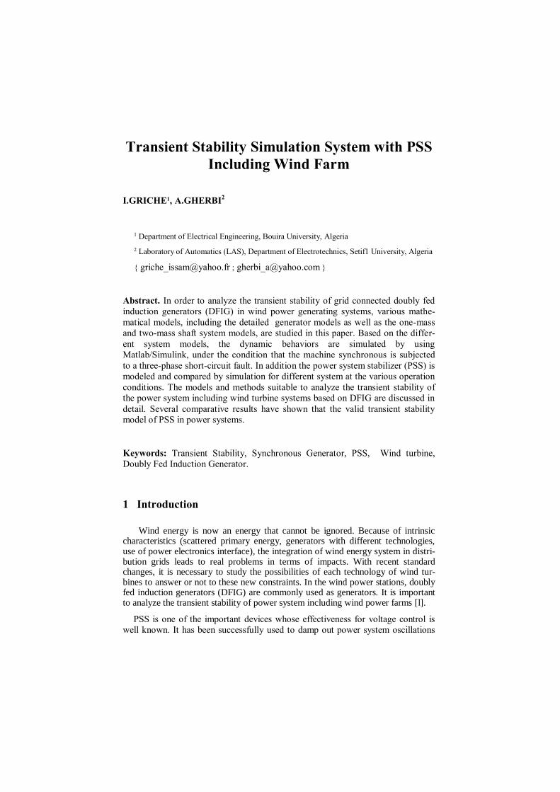
The wind model has been developed at RISØ National Laboratory based on the Kaimal spectra [10]. The wind speed is calculated as an average value of the fixed-point wind speed over the whole rotor, and it takes the tower shadow and the rota-tional turbulences into account. A main component in this model is the normally distributed white noise generator. Therefore, in order to obtain the same wind time series in all considered simulation tools used in the simulation platform, some in-vestigations have been done. It has been found that the built-in white noise genera-tor from different simulation tools uses a different algorithm and thus a different wind time series is obtained. In order to validate the new white noise generator model some comparisons have been done. A wind time series for 3600 sec with 0.05 sec sample time.
5
Fig. 4. The wind profile
Wind turbine rotor model
The aerodynamic model of the wind turbine (WT) rotor is based on the torque
coefficient QC or the power coefficient PC . The torque coefficient QC is used to
determine the aerodynamic torque directly by using:
30.5wt QT R V C (8)
Where is the air density, R is the blade radius,V is the wind speed, QC is
the torque coefficient.
Alternatively, the aerodynamic torque can be determined using the power coef-
ficient PC based on:
2 30.5wt PT R V C (9)
It is important to underline that both coefficients PC and QC can be function of
the tip speed ratio for passive-stall wind turbines or function of tip speed ratio
and pitch angle for active stall and variable pitch/speed wind turbines. The
parameters for this model are: blade radius, air density, cut-in and cut-out wind speeds, as shown in appendix. Using a reduced look-up table in respect with the variation of the torque coefficient/power coefficient with the pitch angle
( 10 10 ) , the model for the active-stall wind turbine is obtained. Imposing
a zero value for the pitch angle the model for passive stall wind turbine can be
obtained.
Drive train model
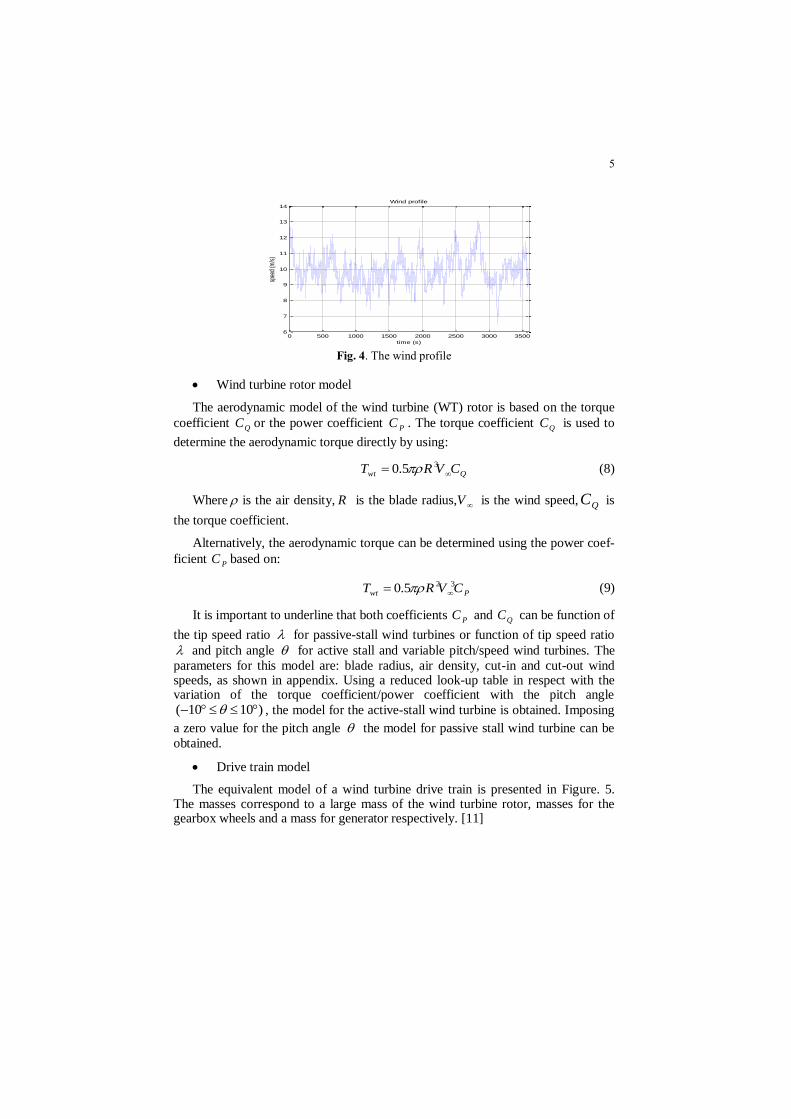
The equivalent model of a wind turbine drive train is presented in Figure. 5. The masses correspond to a large mass of the wind turbine rotor, masses for the gearbox wheels and a mass for generator respectively. [11]
0 500 1000 1500 2000 2500 3000 35006
7
8
9
10
11
12
13
14
time (s)
spee
d (m
/s)
Wind profile
6
Fig.5. Model of a wind turbine drive train
Taking into account the stiffness and the damping factors for both shafts, the
dynamic equations can be written as follows:
1wtr
wtr wtr wtr wtr swtr wtr
dT J D K
dt
(10)
11 1 1 1wtr swtr wtr
dT J D K
dt
(11)
2 22 2 2gen sgen gen
d dT J D K
dt dt
(12)
2
gen
gen gen gen gen sgen gen
dT J D K
dt
(13)
2 1
1
gear
T TK
(14)
Such as:
wtrwtr
d
dt
,
gen
gen
d
dt
; ; 1,2i
i
di
dt
; 2 1gearK , (15)
Where: wtrT is the wind turbine torque, 1T is torque that goes in the gearbox, 2T is
the torque out from the gearbox, wtrJ is the WT moment of inertia, wtr is the WT
mechanical speed, swtrK is the spring constant indicating the torsion stiffness of
the shaft on wind turbine part, genT is the generator torque, genJ is the generator
moment of inertia, gen is the generator mechanical speed, sgenK is the spring
constant indicating the torsion stiffness of the shaft on generator part.
4.2 Doubly-Fed-Induction model
Some of the machine inductances are functions of the rotor speed, whereupon
the coefficients of the state-space equations (voltage equations), which describe
the behavior of the induction machine, are time varying (except when the rotor is
at stand-still). A change of variables is often used to reduce the complexity of the-
se state-space equations. There are several changes of variables, which are used
but there is just one general transformation [8]. This general transformation refers
7
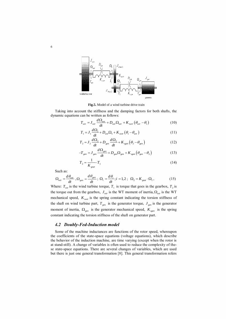
the machine variable to a frame of reference, which rotates at an arbitrary angular
velocity g . In this reference frame, the machine windings are replaced with
some equivalent windings as shown in Figure. 6.
Fig.6. Induction machine windings in the dq0- reference frame
The basic equation of the machine is:
d
V R Idt
(16)
Based on eq. (16) and using the general transformation, the voltage equations in
the arbitrary reference frame can be written as:
d
V R Idt
(17)
The relation between the linkage fluxes and currents is given by:
Or in compact form:
L I (18)
The electromagnetic torque can be obtained starting from eq. (16) and multiply-
ing it from the left with the transpose of the currents vector:
t
t t tdI V I R I I I
dt (19)
Where:
VIPt
i is the instantaneous power.
t
copperP I R I are the copper losses in the machine windings.
t
mag
dP I
dt
is the magnetic power stored in machine (due to the varia-
tion in time of the magnetic energy).
t
mP I is the mechanical power.
The electromagnetic torque is then:

8
3
2
m me sd sq sq sd
r r
P PT p p i i
(22)
With p is the number of pole pairs and r is the mechanical speed of the rotor.
4.3 Power converter model
Currently, in wind turbine applications the back-to-back voltage source con-
verter (VSC) is mainly used. A block diagram of this power converter is shown in
Figure. 7. This topology comprises a double conversion from AC to DC and then
from DC to AC. Both converters can operate in rectifier or inverter mode.
Fig.7. Structure of the back-to-back voltage source converter
A voltage source converter can be implemented in several ways: six-step, pulse
amplitude modulated (PAM) or pulse width modulated (PWM). Moreover, the
implementation of a PWM VSC may be performed by three methods: harmonic
elimination, “sinusoidal” PWM or space vector strategy (SV-PWM). The DC-link
voltage, which is the voltage at the capacitor terminals, is given by:
1 1
DC C R IV i dt i i dtC C
(23)
Where Ri is the current of the generator in side converter and Ii is the current
of the grid side converter
5 Case study and simulation
In order to validate the presented models, the results of simulating a heavy and
a relatively weak disturbance in the system shown in Figure 8 are described. The
system is modeled by a source behind an impedance that is connected to a syn-
chronous generator through a transmission line. A wind farm consisting of doubly-
fed induction generators with a rating of 2 MW is connected to the mid-point of
the transmission line. Each doubly-fed induction generator is modeled according
to Figure 5, including a three winding transformer, the induction generator, the
grid-side and the rotor-side converter and the intermediate DC circuit Figure 9.
Time domain simulations under Matlab-Simulink environment are performed for a
strong three-phase fault of 0.1 sec applied to the grid impedance in several times.
9
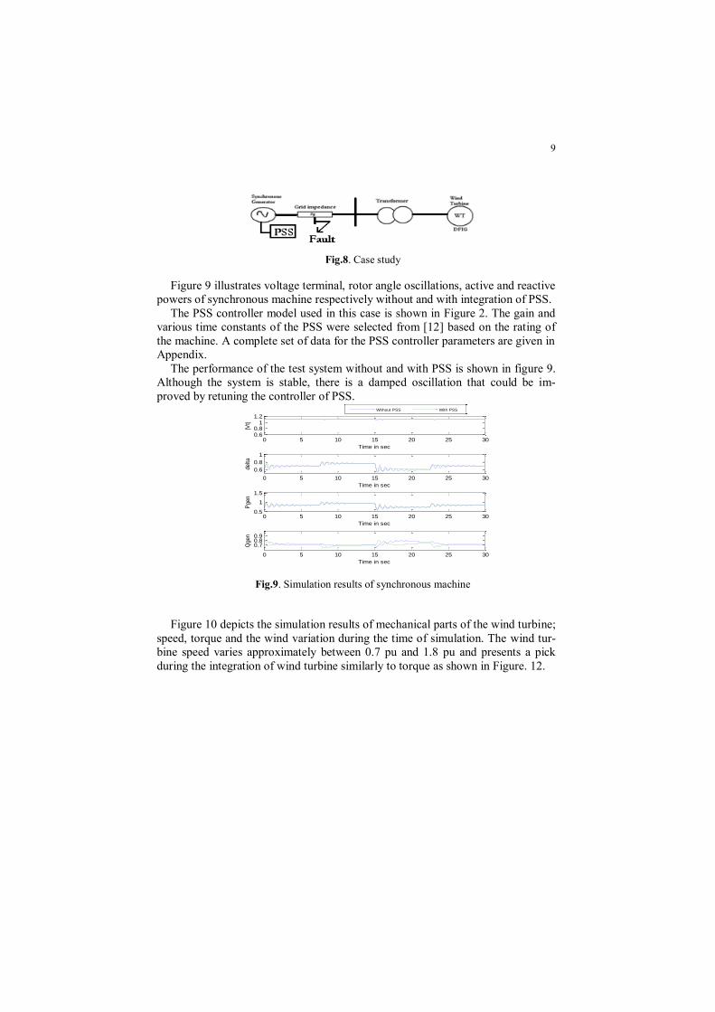
Fig.8. Case study
Figure 9 illustrates voltage terminal, rotor angle oscillations, active and reactive
powers of synchronous machine respectively without and with integration of PSS.
The PSS controller model used in this case is shown in Figure 2. The gain and
various time constants of the PSS were selected from [12] based on the rating of
the machine. A complete set of data for the PSS controller parameters are given in
Appendix.
The performance of the test system without and with PSS is shown in figure 9.
Although the system is stable, there is a damped oscillation that could be im-
proved by retuning the controller of PSS.
Fig.9. Simulation results of synchronous machine
Figure 10 depicts the simulation results of mechanical parts of the wind turbine;
speed, torque and the wind variation during the time of simulation. The wind tur-
bine speed varies approximately between 0.7 pu and 1.8 pu and presents a pick
during the integration of wind turbine similarly to torque as shown in Figure. 12.
0 5 10 15 20 25 300.60.8
11.2
Time in sec
|Vt|
0 5 10 15 20 25 30
0.6
0.8
1
Time in sec
delta
0 5 10 15 20 25 300.5
1
1.5
Time in sec
Pgen
0 5 10 15 20 25 30
0.70.80.9
Time in sec
Qgen
Without PSS With PSS

10
Fig.10. Simulation results of wind turbine with DFIG (Mechanical parts)
The electromagnetic torque is is equal to 0 between the time simulation 0 to 10
sec then it builds a envelope signals, the speed electromagnetic of wind turbine
varies between 156.5 and 155 rad/s. On the other hand, the torque of the drive
train varies between 1000 and 2000 N.m during the all time of simulation as
shown in Figure 11.
Fig.11. Simulation results of wind turbine with DFIG (Mechanical parts)
Several simulation results have been presented in this study under Matlab-
Simulink environment by considering wind generator connected to infinite bus.
These results show the reactions of the wind turbine during given disturbances
such as wind fluctuation of and the short circuit three-phase.
Figures 12 and 13 present respectively the simulation results of the stator and the
rotor currents following the d−axis, q−axis and homopolar axis.
0 5 10 15 20 25 30-2
0
2x 10
4 Tem
0 5 10 15 20 25 30150
155
160
165Wem
0 5 10 15 20 25 300
2000
4000
6000Tsheft
time in sec

11
Fig.12. Simulation results of wind turbine with DFIG (Electrical parts)
The electric quantities (power or currents) are also very disturbed by the fluctu-
ations of wind and the short circuit applied: the statorique or rotorique currents
values is 4 times higher than the rated current, even more significant, is its conse-
quence of the asynchronous machine demagnetization.
Fig.13. Simulation results of wind turbine with DFIG (Electrical parts)
5 Conclusion
In order to investigate the models and methods for the transient stability analy-
sis of DFIG based wind turbines system, some methods to improve the power sys-
tem stability including PSS are presented. Several system models with different
generator models and drive train models of wind turbines are established in this
paper.
Under Matlab-Simulink environment, simulations have been done when the
synchronous is subjected to the three-phase short circuit fault. The application of
the proposed model demonstrates the effect of the PSS on the grid. Using this
0 5 10 15 20 25 300
2000
4000
6000Ird
0 5 10 15 20 25 30-200
-100
0
100Irq
0 5 10 15 20 25 30-5
0
5
10x 10
-13 Ir0
time in sec
0 5 10 15 20 25 30-1
0
1Is0
0 5 10 15 20 25 30-1
0
1x 10
4 Isd
0 5 10 15 20 25 30-1
0
1x 10
4 Isq
time in sec

12
model, the dynamic characteristics of power system stability can be estimated.
Moreover, for future work, the transient stability of the multi-machine power
system including wind farms and the system FACTS combined with this model
should be studied.
5 Appendix
The generator parameters in per unit are as follows:
dX = 1.790, qX =1.660,'
dX = 0.355,'
qX = 0.570,
aR = 0.0048, lX = 0.215,'
0dT = 7.9, '
0qT =0.410, H =3.77, D =0.
The PSS Parameters are as follows:
PSSK =120 wT =1.0 1T =0.024 2T =0.002 3T = 0.024 4T =0.24
The exciter parameters in per unit are as follows:
AK = 50, AT =0.06, RMaxV = 1, RMinV = -1, ET = 0.052, EK = -0.0465,
FT = 1.0, FK = 0.0832, ExA = 0.0012,
ExB = 1.264.
The wind turbine parameters:
Stator parameters [Rs (Ω), Lsgm_s(H)] =[3.67, 9.2 10-3
].
Rotor parameters [Rr (Ω) Lsgm_r (H)] =[2.32 ,12.29 10-3
].
Magnetizing inductance [H]: Lm=0.235.
Number of poles pair: pw=2.
References
[1] T. Petru and T. Thiringer, “Modeling of wind turbines for power system
studies,” IEEE Trans. Power Syst., vol. 17, no. 4, pp. 1132–1139, Nov. 2002.
[2] J. L. Rodriguez-Amenedo, “Automatic Generation Control of a Wind Farm
With Variable Speed Wind Turbines,” IEEE Transactions on Energy
Conversion, Vol 17, No. 2, June 2002.

13
[3] Claudio L.Souza et. al., “Power System Transient Stability Analysis
including Synchronous and Induction Generator,” IEEE Porto Power Tech
Proceedings, Vol.2, pp.6, 2001.
[4] P. Ledesma, J. Usaola, J.L. Rodriguez, “Transient stability of a fixed speed
wind farm”, Elsevier Science, 5 August 2002.
[5] A.Sanai Sabzevaty, Manabu Sakata, Yam0 Tamura: ”Robust Quadratic
Stabilization of Power System”, The Fourth h u a l Conference of Power
[6] J. G. Slootweg, S. W. H. de Haan, H. Polinder, W. L. Kling, “Aggregated
Modelling of Wind Parks with Variable Speed Wind Turbines in Power
System Dynamics Simulations,” Proc. of the 14th Power Systems
Computation Conference, Sevilla, 2002.
[7] J. B. Ekanayake, L. Holdsworth, X. G. Wu, and N. Jenkins, “Dynamic
modeling of doubly fed induction generator wind turbines,” IEEE Trans.
Power Syst., vol. 18, no. 2, pp. 803–809, May 2003.
[8] A. Tapia, G. Tapia, J. X. Ostolaza, and J. R. Saenz, “Modeling and control of
a wind turbine driven doubly fed induction generator,” IEEE Trans. Energy
Convers., vol. 18, no. 2, pp. 194–204, Jun. 2003.
[9] P. Kundur, Power System Stability and Control, McGraw-Hill, Inc.1993
[10] Sorensen, P., Hansen, A.D., Rosas, P.A.C. – Wind models for simulation of
power fluctuations from wind farms, Journal of Wind Engineering, 90, 2002,
pp. 1381-1402.
[11] Shaltout, A. “Analysis of torsional torques in starting of large squirrel cage
induction motors,” IEEE Trans. on Energy Conversion, Vol. 9, No. 1. March
1994, pp. 135-141.
[12] N. Dizdarevic, Uni_ed Power Flow Controller in Alleviation of Voltage
Stability Problem , Doctoral thesis, Zagreb,2001.