Transient Analysis of Three-Phase Wound Rotor (Slip-Ring) Induction Motor...
14
International Journal of Recent Engineering Research and Development (IJRERD) ISSN: 2455-8761 www.ijrerd.com || Volume 02 – Issue 07 || July 2017 || PP. 19-32 19 | P a g e www.ijrerd.com Transient Analysis of Three-Phase Wound Rotor (Slip-Ring) Induction Motor under Operating Condition Obute K.C. 1 , Enemuoh F.O. 1 1 – Department of Electrical Engineering Nnamdi Azikiwe University Awka, Anambra State Nigeria Corresponding Author - Obute Kingsley Chibueze Department of Electrical Engineering Nnamdi Azikiwe University Awka, Anambra State Nigeria Abstract: This work investigates the transient behaviours of a three phase wound rotor type induction motor, running on load. When starting a motor under load condition becomes paramount, obviously a wound rotor (slip ring) induction becomes the best choice of A.C. motor. This is because maximum torque at starting can be achieved by adding external resistance to the rotor circuit through slip-rings. Normally a face-plate type starter is used, and as the resistance is gradually reduced, the motor characteristics at each stage changes from the other (John Bird 2010). Hence, the three phase wound rotor (slip ring) induction motor competes favourably with the squirrel cage induction motor counterpart as the most widely used three-phase induction motor for industrial applications. The world-wide popularity and availability of this motor type has attracted a deep – look and in-depth research including its transient behavior under plugging (operating) condition. This paper unveils, through mathematical modeling, followed by dynamic simulation, the transient performance of this peculiar machine, analyzed based on Park’s transformation technique. That is with direct -quadrature-zero (d-q-o) axis based modeling in stationary reference frame. Key Words: Transient Condition, d-q-0 reference frame, a-b-c reference frame, arbitrary reference frame, stationary reference frame, and wound rotor induction motor etc. Introduction When a circuit possess energy-storing element such as inductance and capacitance, the energy state of the circuit can be disturbed by changing the position of the switch connecting the elements to the source. The circuit then settles down to another steady state after a certain time. (Smarajit Ghosh 2011). Interestingly, the behavior of all electrical machines is only of interest when it is in a steady-state. There exist some cases, however, when the temporary response of a machine to a change in conditions is required. For instance, if a power supply in a machine is switched on, there may be a surge, possibly with oscillation before a steady flow of current is established. This surge (burst of energy) is short-lived and instantnous, and is caused by a sudden change of state of the machine. Circuits exhibit transient when they contain active components, that can store energy, such as transformers and induction motors. Transient phenomenon is an aperiodic function. The duration for which it lasts is very insignificant as compared with the operating time of the system. Yet they are very important because, depending upon the severity of these transients, the system may result into shut down of a plant etc. (Wadjwa 2009). Every electrical system can be considered as made up of linear impedance of elements resistance, inductance and capacitance. For the slip-ring induction motor under discussion, its circuit is normally energized and carries mechanical load, until a fault suddenly occurs. The fault, then corresponds to the closing of a switch (or switches, depending upon the type of fault). The closing of this/these switch(es) charge(s) the circuit, so that a new distribution of currents and voltages is brought about. This redistribution is accompanied in general by a transient period during which the resultant currents and voltages may momentarily be relatively high. It pays to realize that this redistribution of currents and voltages cannot take place instantaneously for the following reason: a) The electromagnetic energy stored by an inductance (L)(main component of every electrical machine) is 0.5 LI 2 , where I is the instantaneous value of current. Assuming inductance to be constant, the change in magnetic energy requires change in current which an inductor is opposed by an e.m.f of magnitude L . In order to change the current instatenousely dt = 0 and therefore L = (infinity). This suggests that to bring about instantaneous change in current the e.m.f. in the inductor should become infinity which is practically impossible. Hence the charge of energy in an inductor is gradual, and therefore the redistribution of energy following a circuit change takes a finite time.
Transcript of Transient Analysis of Three-Phase Wound Rotor (Slip-Ring) Induction Motor...

IJRERD
International Journal of Recent Engineering Research and Development (IJRERD)
ISSN: 2455-8761
www.ijrerd.com || Volume 02 – Issue 07 || July 2017 || PP. 19-32
19 | P a g e www.ijrerd.com
Transient Analysis of Three-Phase Wound Rotor (Slip-Ring)
Induction Motor under Operating Condition
Obute K.C.1, Enemuoh F.O.
1
1 – Department of Electrical Engineering Nnamdi Azikiwe University Awka, Anambra State Nigeria
Corresponding Author - Obute Kingsley Chibueze
Department of Electrical Engineering
Nnamdi Azikiwe University Awka, Anambra State Nigeria
Abstract: This work investigates the transient behaviours of a three phase wound rotor type induction motor,
running on load. When starting a motor under load condition becomes paramount, obviously a wound rotor (slip
ring) induction becomes the best choice of A.C. motor. This is because maximum torque at starting can be
achieved by adding external resistance to the rotor circuit through slip-rings. Normally a face-plate type starter
is used, and as the resistance is gradually reduced, the motor characteristics at each stage changes from the
other (John Bird 2010). Hence, the three phase wound rotor (slip ring) induction motor competes favourably
with the squirrel cage induction motor counterpart as the most widely used three-phase induction motor for
industrial applications. The world-wide popularity and availability of this motor type has attracted a deep – look
and in-depth research including its transient behavior under plugging (operating) condition. This paper unveils,
through mathematical modeling, followed by dynamic simulation, the transient performance of this peculiar
machine, analyzed based on Park’s transformation technique. That is with direct-quadrature-zero (d-q-o) axis
based modeling in stationary reference frame.
Key Words: Transient Condition, d-q-0 reference frame, a-b-c reference frame, arbitrary reference frame,
stationary reference frame, and wound rotor induction motor etc.
Introduction When a circuit possess energy-storing element such as inductance and capacitance, the energy state of
the circuit can be disturbed by changing the position of the switch connecting the elements to the source. The
circuit then settles down to another steady state after a certain time. (Smarajit Ghosh 2011). Interestingly, the
behavior of all electrical machines is only of interest when it is in a steady-state. There exist some cases,
however, when the temporary response of a machine to a change in conditions is required. For instance, if a
power supply in a machine is switched on, there may be a surge, possibly with oscillation before a steady flow
of current is established. This surge (burst of energy) is short-lived and instantnous, and is caused by a sudden
change of state of the machine.
Circuits exhibit transient when they contain active components, that can store energy, such as
transformers and induction motors. Transient phenomenon is an aperiodic function. The duration for which it
lasts is very insignificant as compared with the operating time of the system.
Yet they are very important because, depending upon the severity of these transients, the system may result into
shut down of a plant etc. (Wadjwa 2009).
Every electrical system can be considered as made up of linear impedance of elements resistance,
inductance and capacitance. For the slip-ring induction motor under discussion, its circuit is normally energized
and carries mechanical load, until a fault suddenly occurs. The fault, then corresponds to the closing of a switch
(or switches, depending upon the type of fault). The closing of this/these switch(es) charge(s) the circuit, so that
a new distribution of currents and voltages is brought about. This redistribution is accompanied in general by a
transient period during which the resultant currents and voltages may momentarily be relatively high. It pays to
realize that this redistribution of currents and voltages cannot take place instantaneously for the following
reason:
a) The electromagnetic energy stored by an inductance (L)(main component of every electrical machine) is
0.5 LI2, where I is the instantaneous value of current. Assuming inductance to be constant, the change in
magnetic energy requires change in current which an inductor is opposed by an e.m.f of magnitude L 𝑑𝐼
𝑑𝑡.
In order to change the current instatenousely dt = 0 and therefore L 𝑑𝐼
𝑂 = (infinity). This suggests that to
bring about instantaneous change in current the e.m.f. in the inductor should become infinity which is
practically impossible. Hence the charge of energy in an inductor is gradual, and therefore the
redistribution of energy following a circuit change takes a finite time.

IJRERD
International Journal of Recent Engineering Research and Development (IJRERD)
ISSN: 2455-8761
www.ijrerd.com || Volume 02 – Issue 07 || July 2017 || PP. 19-32
20 | P a g e www.ijrerd.com
b) Another component, the resistance R (also obtainable at the stator/rotor windings) consumes energy. At any
time, the principle of energy conservation in an electrical circuit applies. That is the rate of generation of energy
is equal to the rate of storage of energy, plus the rate of energy consumption.
In its summarized form, it becomes clear that in any rotating machine;
i) the current cannot change instantaneously through an inductor (winding)
ii) the law of conservation of energy must hold good, are fundamental to the phenomenon of transient in
electric machine.
Also from the above explanations, it can be said that in order to have transients in an electrical machine with
special reference to three phase wound rotor (slip ring) induction motor, the following requirements should be
met.
i) The inductor (windings) should be present
b) A sudden change in the form of a fault or any switching operation should take place.
2- THE TRANSIENT MATHEMATICAL MODELLING OF THE MOTOR USING PARK’S
TRANSFORMATION TECHNIQUE Unlike the steady state mathematical modeling of induction motors, which is not new and has received
a considerable attention from researchers, the transient mathematical modeling of induction motors continues to
received much attentions. This is as a result of the vital effect the transient behavior of the induction motors has
on the overall performance of the system to which it forms a component part. Transient modeling of induction
motors prove to be more difficult both in the definition of suitable forms of equations and in the application of
appropriate numerical methods needed for the solution of same (Okoro 2003).
The three phase wound rotor (slip-ring) induction motor is modeled using Park’s transformation technique
(Direct-quadrature-zero (d-q-o) axis transformation theory).
In electrical engineering, and other associated disciplines, the analyses of three-phase circuits are mostly
simplified using d-q-o transformation.
It is a more reliable and accurate technique for investigating the problems of voltage drips, oscillatory torques
and harmonics in electrical system, which arise due to high currents drawn by all induction motors when they
are started and during the other transient operations.
The three reference frames includes;
i) Stationary reference frame
ii) Rotor reference frame
iii) Synchronous reference frame
These reference frames are used to convert the a-b-c reference frame (input voltage) to the d-q-o
reference frame, and/output current (d-q-o reference frame) to the a-b-c reference frame.
Any one of the afore-mentioned three reference frame can be used to analyze the transient dynamic behavior of
the three phase motor under consideration, based on the following conditions;
i) If the stator voltage is unbalanced and the rotor voltages are balanced, the stationary reference frame is
useful
ii) If the rotor voltages are unbalanced and stator voltages are balanced, the rotor reference frame is used
iii) If the stator and rotor voltages are balanced and continuous, then synchronous reference frame is used
2.1 – TRANSFORMATION OF a-b-c TO d-q-o REFERENCE FRAME
The transformations like d-q-o developed by park can facilitate the computation of the transient solution of the
three-phase wound rotor induction motor model by transforming inductances to differential equations with
constant inductances.
2.2- Equations of Induction Motor in Arbitrary d-q-o Reference Frame
The relationship between the abc quantities and qdo quantities of a reference frame rotating at an angular
speed, w, is shown in figure 1 below;

IJRERD
International Journal of Recent Engineering Research and Development (IJRERD)
ISSN: 2455-8761
www.ijrerd.com || Volume 02 – Issue 07 || July 2017 || PP. 19-32
21 | P a g e www.ijrerd.com
The transformation equation from a-b-c to this d-q-o reference frame is given by:
by: 1...
c
b
a
qdo
o
d
q
f
f
f
T
f
f
f
Where the variable f can be the phase voltage, currents or flux linkages of the machine. The first
quadrant of the reference frame rotating at an arbitrary speed w (t), in figure 1 is shown as demarcated. The
transformation angle, (t), between the q-axis of the reference frame rotating at w and the a-axis of stationary
stator winding may be expressed as:
2....0( radelectdttwt t
o
Likewise, the rotor angle, tr , between the axes of the stator and the rotor a-phases for a rotor
rotating with speed twr may be expressed as
3....0( radelectdttwt rr
t
or
The angles (0) and r (0) are the initial values of those angles at the beginning of time t.
The qdo transformation matrix, qdoT is
4...
2
1
2
1
2
1
32sin
32sinsin
32cos
32coscos
3
2
qdoT
And its inverse is
5...
13
2sin3
2cos
13
2sin3
2cos
1sincos
1
qdoT
2.3 – d-q-o Voltage Equations
In matrix notation, the stator windings a b c voltage can be expressed as
abc
S
abc
S
s
abc
abc
S irpV …6
Applying the transformation to equation (6), we obtain
Cr Cs
br
bs
d-axis
a-axis
Wr
Ѳr
q-axis
w
Figure 1 - Relationship between
abc and arbitrary d-q-o

IJRERD
International Journal of Recent Engineering Research and Development (IJRERD)
ISSN: 2455-8761
www.ijrerd.com || Volume 02 – Issue 07 || July 2017 || PP. 19-32
22 | P a g e www.ijrerd.com
biTrTTpTV
airTpTVT
qdo
sqdo
abc
sqdo
S
qdoqdqdo
qdo
S
abc
S
abc
Sqdo
S
abcqdo
abc
sqdo
7...
7...
11
0
8...
03
2cos3
2sin
03
2cos3
2sin
0cossin
13
2sin3
2cos
13
2sin3
2cos
1sincos
11
1
qdo
Sqdo
qdo
sqdo
qdo
pTwTp
T
Substituting equation (8) back into equation (7b) gives:
9.
100
010
001
03
2cos3
2sin
03
2cos3
2sin
0cossin
1 qdo
Ss
qdo
sqdo
qdo
Sqdo
qdo
S irpTwTV
Rearranging (9) will give:
10....
000
001
010qdo
S
qdo
S
qdo
S
os
ds
qs
qdo
S irpwV
Where, dt
dw
,
and
11...
ossosos
dssdsqsds
qssqsdsqs
irpV
irpwV
irpwV
2.4 – q-d-o Transformation Of The Rotor
12...abc
rabcr
abc
r pirv
The rotor quantities must be transformed on the same d-q-o frame. The transformation angle to the
rotor phase quantities is ( - r). Therefore T ( - r) is the transformation angle.
13...
2
1
2
1
2
1
3
2sin
3
2sinsin
3
2cos
3
2coscos
3
2
rrr
rrr
rT
14...
13
2sin
3
2cos
13
2sin
3
2cos
1sincos
1
rr
rr
rr
rT
Applying the transformation matrix to equation 14 in the same manner as in that of the stator, the
equation will be obtained as: (V. Sarac et al 2013)
airpwwV qdo
r
qdo
r
qdo
r
qdo
rr
qdo
r 15...
000
001
010
.
dt
dp
rr S
qdo
s
100
010
001

IJRERD
International Journal of Recent Engineering Research and Development (IJRERD)
ISSN: 2455-8761
www.ijrerd.com || Volume 02 – Issue 07 || July 2017 || PP. 19-32
23 | P a g e www.ijrerd.com
From equation 15a, the park equations are:
b
irpV
irpwwV
irpwwV
orororor
drdrdrqrrdr
qrqrqrdrrqr
15....
2.5 d-q-o Flux Linkage Relation
The stator qdo flux linkages are obtained by applying Tqdo(Ѳ) to the stator abc flux linkages of equation (16),
that is:
16...abc
r
abc
Sr
abc
S
abc
SS
abc
S iLiL
Using appropriate transformation, we obtain:
aiTLTiTLT
iTLTiTLTT
qdo
rrqds
abc
Srqd
qdo
Sqdo
abc
SSqdo
qdo
S
qdo
rr
abc
SS
qdo
s
abc
SSqdo
abc
S
17...
17...
1
0
1
11
Equation (17) gives rise to:
biL
L
i
L
LL
LL
qdo
rSr
Sr
qdo
S
LS
SSSL
SSLS
qdo
s 17...
000
02
30
002
3
00
02
30
002
3
.
Similarly, the qdo rotor flux linkage can be derived as,
abc
r
abc
rr
abc
S
abc
rS
abc
r iLiL .
Applying the transformation: qdo
r
abc
rrr
qdo
Ssrr
abc
rr iTLTiTLTT11
aiTiTLT qdo
rrqdo
qdo
sqdo
abc
rSrqdo
qdo
r 18...11
This gives:
bi
L
LL
LL
iL
L
qdo
r
Lr
rrLr
rrLr
qdo
ssr
sr
qdo
r 18...
00
02
30
002
3
000
02
30
002
3
.
The stator and rotor flux linkage relationships in equations (17b and 18b) an be expressed compactly as
19...
00000
0000
0000
00000
0000
0000
'
'
'
'
'
'
'
'
'
or
dr
qr
os
ds
qs
Lr
mLrm
Lrm
Ls
mmLS
mmLS
or
dr
qr
oS
dS
qS
i
i
i
i
i
i
L
LLL
LL
L
LLL
LLL
Where,
22...
21...,
20...,
2
'
''
''
LrLr
drdrqrqr
drdrqrqr
LNr
NsL
iNs
Nrii
Ns
Nri
Nr
Ns
Nr
Ns
IJRERD
International Journal of Recent Engineering Research and Development (IJRERD)
ISSN: 2455-8761
www.ijrerd.com || Volume 02 – Issue 07 || July 2017 || PP. 19-32
24 | P a g e www.ijrerd.com
And Lm, the magnetizing inductance on the stator side, is: 23...2
3
2
3
2
3rr
r
s
sr
r
s LN
NL
N
NLssLm
From equation (11) and equation (15b),
For stator,
For rotor
Also, flux linkage of equation 19 can be written as:
b
iL
iiLiL
iiLiL
iiLiL
iLiLL
iiLiL
iLiLL
orlror
drdsmdrlrdr
qrqsmqrlrqr
drds
mdsls
drmdsmlsds
qrqsmqsls
qrmqsmlsqs
19...
''
''
''''
'
Substituting the values of flux in the rotor and stator voltage equations (11) and (15b) gives:
''''
''''''
''''
'
'
(
orlrorror
ossossos
drdsmdrlrqrrdrrdr
drmdsmlsqsdssds
qrqsmqrlrdrrqrrqr
qrqsmqslsdsqssqs
iLpirV
iLpirV
iiLiLpwwirV
iLiLLpwirV
iiLiLpwwirV
liLiLpwirV
In terms of sx , and s, stator and rotor voltage equations (.24) can be written as:
osossos
dsqsqssds
qssqssqs
pirV
pwirV
pdwirV
''''
'''''
'''''
ororror
drqrrdrrdr
qrdrrqrrqr
pirV
pwwirV
pwwirV
…24

IJRERD
International Journal of Recent Engineering Research and Development (IJRERD)
ISSN: 2455-8761
www.ijrerd.com || Volume 02 – Issue 07 || July 2017 || PP. 19-32
25 | P a g e www.ijrerd.com
25...
'
0
''
0
'
0
'''''
'''''
000
rrr
b
r
drrqr
b
b
dr
b
dr
qrrdr
b
r
qr
b
qr
sss
b
s
dssqs
b
ds
b
ds
qssds
b
ds
b
qs
irw
pv
irw
ww
w
pv
irw
ww
w
pv
irw
pv
irw
w
w
pv
irw
w
w
pv
Where
26...
'
'
'
0
'
'
'
'
'
'
or
dr
qr
s
ds
qs
Lr
mLrm
mLrm
ls
mmls
mmls
or
dr
qr
os
ds
qs
i
i
i
i
i
i
xooooo
oxxooxo
ooxxoox
oooxoo
oxooxxo
ooxooxx
Where bw
2.6–q-d-0 Torque Equation in Arbitrary Reference Frame
The sum of the instantaneous input power to all six windings of the stator and rotor is given by
27...''''
crcararcscsbsbsasasni iViViViViVP
In terms of q-d-0 quantities, the instantaneous input power is
28...22
2
3 '''''
orordrdrqrqrososdsdsqsqs iViViViViViVPin
Substituting the values of '' ,,, drqrdsqs VVVV from equation (10) and (15a) into the right side of equation (28), we
obtain;
29...
2
3
''''''
'
drqrrdrrdrrqrrqrr
drdsqsdssdsqsdsqssqsin
pwwirwwirir
ipwiripwiriP
From equation (29), we obtain 3 kinds of terms: i
2r, i p , and i terms. The i
2r terms are copper losses;
the i p terms represent the rate of exchange of magnetic field energy between windings. The w i terms
represent the rate of energy converted to mechanical work. That is
'''1.
2
3drqrqrdrrdsqsqsds
m
em iiwwiiww
T
But p
ww b
m
2
30...22
3 '
drqrqrdrrdsqsqsds iiwwiiwwb
PTem
Substituting values of '' ,,, drqrdsqs from equation (19b) into equation 30, we have
..26

IJRERD
International Journal of Recent Engineering Research and Development (IJRERD)
ISSN: 2455-8761
www.ijrerd.com || Volume 02 – Issue 07 || July 2017 || PP. 19-32
26 | P a g e www.ijrerd.com
'
'
]
qrdsdsqsm
qsmdsqsmdsqsls
qsdrqsdsmqsdslsdsqsqsds
iiiiL
iLiiLiLL
iiiiLiiLii
And
qsdsdrqsmqrdrdrqr iiiiLii ''
This implies that
''''
''
drdrdrqsmqrdrdrqr
dsqrqrdrdsqsqsds
iiiiLii
iiii
Therefore,
31...''''
dsqrqrdrmdrqrqrdrdsqsqsds iiiiLiiii
Substituting equation (31) into equation (30) gives;
32...
.22
3
.22
3
.22
3
''
'''
mNiiiiLP
mNiiP
mNiiP
Tem
dsqrqsdrm
dsqsqsds
qrqrdrqr
3–Induction Machine Equation in Stationary Reference Frame By setting w=0 in equation (21) gives:
qs
b
qss
s
qs
qs
b
bqss
s
qs
ososs
s
os
dsdss
s
ds
qsqss
s
qs
w
pirV
w
wpirV
pirV
pirV
pirV
33...
Where bw
Therefore, for stator
34...
'
ossos
b
os
s
dsss
b
s
ds
qssqs
b
s
qs
irw
pV
irw
pV
irw
pV
For rotor
Set w=0 in equation (15b):

IJRERD
International Journal of Recent Engineering Research and Development (IJRERD)
ISSN: 2455-8761
www.ijrerd.com || Volume 02 – Issue 07 || July 2017 || PP. 19-32
27 | P a g e www.ijrerd.com
35...
''
'''''
''''
orror
b
or
s
drr
s
qr
b
rs
qr
b
s
dr
s
drr
s
dr
b
rs
qr
b
s
qr
irw
pV
irw
w
w
pV
irw
w
w
pV
36...
'
'
'
0
'
'
'
'
'
'
or
s
dr
s
qr
s
s
s
ds
s
qs
Lr
mLrm
mLrm
ls
mmls
mmls
s
or
s
dr
s
qr
s
os
s
ds
s
qs
i
i
i
i
i
i
xooooo
oxxooxo
ooxxoox
oooxoo
oxooxxo
ooxooxx
Torque equations,
37....22
3
22
3
22
3
''
'''
mNiiiixw
P
iiw
P
iw
PTem
s
ds
s
qrqs
s
drm
b
s
dsqs
s
qs
s
ds
b
s
qr
s
dr
s
dr
b
3.1 – Equations for Simulation of Induction Motor in Stationary Reference Frame

IJRERD
International Journal of Recent Engineering Research and Development (IJRERD)
ISSN: 2455-8761
www.ijrerd.com || Volume 02 – Issue 07 || July 2017 || PP. 19-32
28 | P a g e www.ijrerd.com
The model equations of the induction machine in the stationary q-d-0 reference frame may be rearranged into the following form for simulation
40...)(
)(
39...
)(
))((
))((
38...
)(
))((
))((
''
''
''
'
'
'
'
'''
'
'
''
s
drs
s
dm
s
mq
s
qrs
s
qm
s
mq
roror
Lr
b
or
s
dr
s
md
rL
rs
dr
b
rs
dsb
s
dr
s
qr
s
mq
rL
rs
dr
b
rs
qrb
s
qr
sosos
LS
b
os
s
ds
s
md
LS
ss
dsb
s
ds
s
qs
s
mq
LS
ss
qsb
s
qs
iix
iix
dtriVx
wi
dtx
r
w
wVw
dtx
r
w
wVw
dtrlVx
wi
dtx
rVw
dtx
rVw
41...
)(,
)(,
,
,
'
'
',','
'
'
','
'
''
Lr
s
md
s
drs
dr
s
dr
s
drLr
s
dr
Lr
s
mq
s
qrs
qr
s
mq
s
qrLr
s
qr
Ls
s
md
s
qss
ds
s
md
s
dsLs
s
ds
Ls
s
mq
s
qss
qs
s
mqqsLsqss
xiix
xiix
xiix
xiix
Where
43...
42...1111
'
'
'
'
'
lr
s
dr
ls
s
ds
M
s
md
lr
s
dr
ls
s
qs
M
s
mq
lrlsmM
xxx
xxx
and
xxxx
The torque equation is
IJRERD
International Journal of Recent Engineering Research and Development (IJRERD)
ISSN: 2455-8761
www.ijrerd.com || Volume 02 – Issue 07 || July 2017 || PP. 19-32
29 | P a g e www.ijrerd.com
Tem mNiiw
P s
ds
s
qs
s
ds
s
qs
b
.)(22
3
The equation of motion of the rotor is obtained by equating the inertia torque to the accelerating torque, that is,
44....mNTTTdt
dwdampmechem
rm
Where Tmech = the externally applied mechanical torque in the direction of the rotor speed.
Tdamp = the damping torque in the direction opposite to rotation.
When equation (44) is used in conjunction with equation (38) and (39), the per unit speed, wr/wb
needed for building the speed voltage terms in the rotor voltage equations, can be obtained by integrating
45....
/2mNTdampTmechTem
dt
wwd
P
Jw brb Equation (45) can be written in terms of the
inertia constant, H, defined as the ratio of the kinetic energy of the rotating mass at base speed to the rated
power, that is
46....2
2
unitperinS
JwH
b
bm Expressed in per unit values of the machine’s own
base power and voltage, equation (45) can be rewritten as
47...
/2 unitperinTTT
dt
wwdH dampmechem
br
4 – SIMULATION RESULTS The reference model we discussed exhaustively above, was tested on a three phase wound rotor (slip-
ring) induction motor, with rating tabulated in table 1 below, to analyze the dynamic behavior of the machine.
Table 1 – Circuit Parameter Values and constants for the dynamic simulation of the three-phase wound rotor
(slip-ring) induction motor (Eleanya 2015),
Circuit parameter Value
Power rating 5hp
Voltage (Line to line) (V) 415v
Frequency (f) 50Hz
No of poles ( Pn) 4
Stator resistance (rs) 0.22Ω
Stator inducdance (Ls) 0.0425H
Rotor resistnace ri 0.209Ω
Rotor induction L𝑟 0.0430H
Magnetizing inductance Lm 0.040H
Moment of inertia of motor J 0.124kgm2
With values of table 1 and using equation 38 through equations 47, the dynamic simulation plots for the
machine is as shown in fig 1 through fig 4
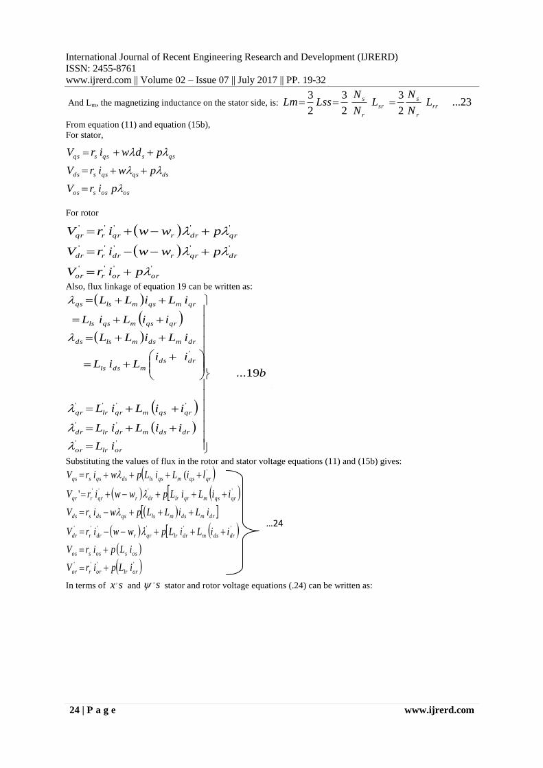
Fig 1: The Electromagnetic Torgue, Te against
rotor speed for the three-phase wound rotor
Induction Motor (IM)
IJRERD
International Journal of Recent Engineering Research and Development (IJRERD)
ISSN: 2455-8761
www.ijrerd.com || Volume 02 – Issue 07 || July 2017 || PP. 19-32
30 | P a g e www.ijrerd.com
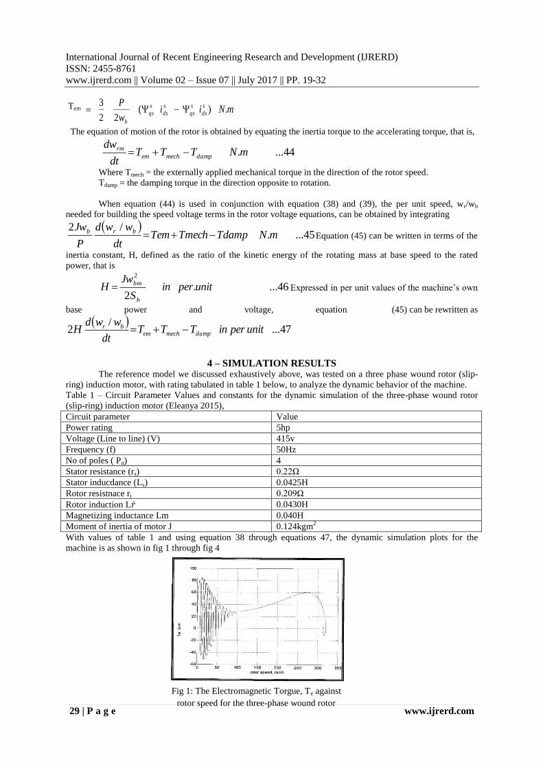
Fig 2: The Electromagnetic Torgue, Te against
time for the three-phase wound rotor Induction
Motor (IM)
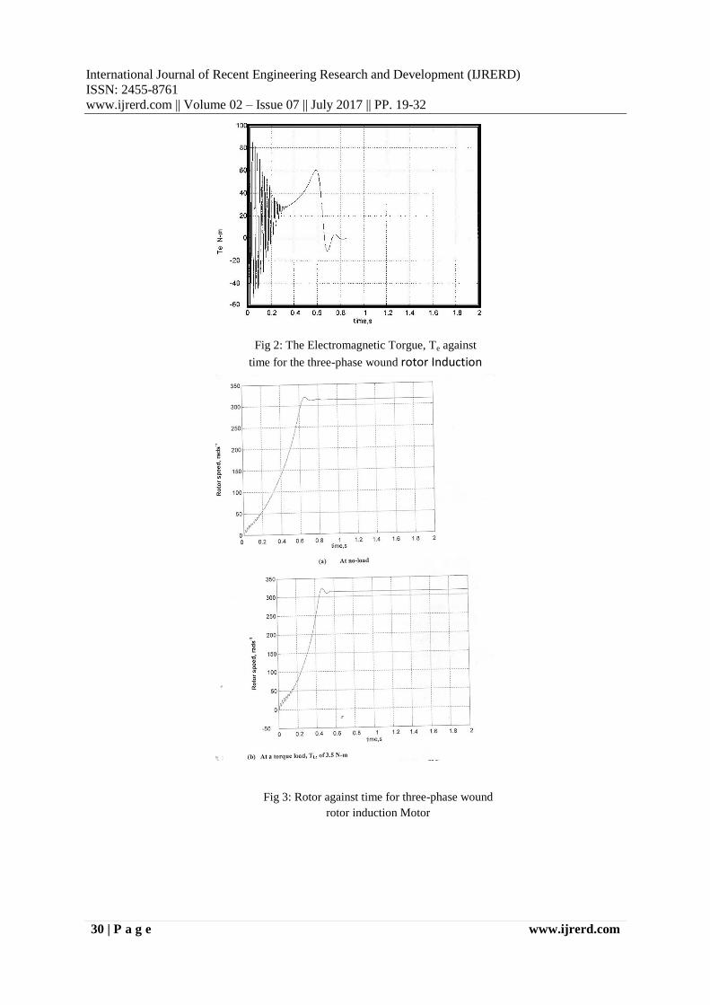
Fig 3: Rotor against time for three-phase wound
rotor induction Motor
IJRERD
International Journal of Recent Engineering Research and Development (IJRERD)
ISSN: 2455-8761
www.ijrerd.com || Volume 02 – Issue 07 || July 2017 || PP. 19-32
31 | P a g e www.ijrerd.com
5 – PERFORMANCE ANALYSIS OF THE MACHINE UNDER TRANSIENT CONDITION From the graphs plotted, and irrespective of the reference frame chosen for the motor, the material
inductance of machine depends on the rotor position which varies with time.
Due to transient condition, the torque Vs speed plotting exhibited characteristics similar to that obtainable under
steady-state condition.
The machine oscillated and settled at a rotor speed of 314 rad s-1
That is at synchronous speed. The
plotting is shown in fig 1.
When the machine was simulated to start on no load, it accelerated freely, and after some damped
oscillation, settles at a synchronous speed, wr = ws = 314 rad s-1
at a time of 0.6 seconds. See fig 3a On the other
round, when it was simulated with load torque of 3.5Nm, the rotor speed did not accelerate freely as it did under
no-load; rather it has few seconds of delayed acceleration, oscillated very briefly and settles at less than the
synchronous speed (wr = 310 rad s-1
), at oscillation time of 1.2 seconds. This is shown in fig 3b.
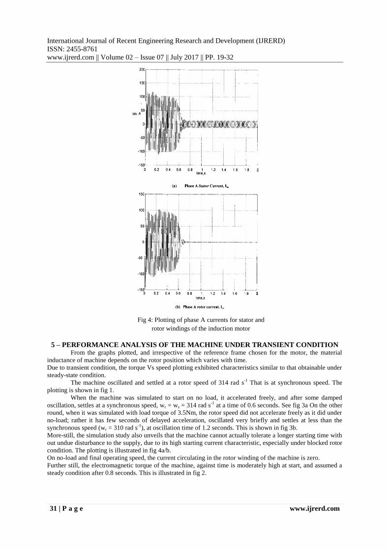
More-still, the simulation study also unveils that the machine cannot actually tolerate a longer starting time with
out undue disturbance to the supply, due to its high starting current characteristic, especially under blocked rotor
condition. The plotting is illustrated in fig 4a/b.
On no-load and final operating speed, the current circulating in the rotor winding of the machine is zero.
Further still, the electromagnetic torque of the machine, against time is moderately high at start, and assumed a
steady condition after 0.8 seconds. This is illustrated in fig 2.
Fig 4: Plotting of phase A currents for stator and
rotor windings of the induction motor

IJRERD
International Journal of Recent Engineering Research and Development (IJRERD)
ISSN: 2455-8761
www.ijrerd.com || Volume 02 – Issue 07 || July 2017 || PP. 19-32
32 | P a g e www.ijrerd.com
6 – Conclusion This work has presented vividly a simple method of analyzing and simulating the transient state
performance of three-phase wound rotor (slip-ring) induction motor under operating condition. The simulation
results presented in this report are indeed indispensable and predictable tools to Electrical Machine Engineers
over the motor performance prior to their designs and constructions.
Acknowledgement The authors acknowledge God Almighty for his protection and their families for their endurance,
tolerance and support during the research work.
References [1]. O. I. Okoro 2003 – Steady-State and transient analysis of induction motor driving a pump load.
Nigerian Journal of Technology, vol 22, No 1, March 2003. Page 46-51
[2]. V. Sarac, G. Cvetkovski 2013-Transient analysis of induction motor using different simulation models.
Acta Technica Jourinensia Vol 6, No. 1.2013 page 69-70
[3]. Mukesh Kumar Arya, Dr. Sulochana Wadhiwani – Transient analysis of three phase squirrel cage
induction machine using matlab. International Journal of Engineering Research and Application
(IJERA), Vol. I Issue 3, Page 918-920.
[4]. John Bird 2010 – Electrical Circuit Theory and Technology Published by Elsevier Ltd page
[5]. Elanya M.N. 2015 – Comparative Analysis of a Transfer field Machine and an induction machine – An
unpublished thesis submitted to the Department of Electrical Engineering, University of Nigeria page
75-78
[6]. Smarajit Ghosh 2011-Network theory (Analysis and Synthesis). Published by Asoke K. Ghosh Page 94