Transforming Collaborative Process Models into … · Transforming Collaborative Process Models...
15
C. Godart et al. (Eds.): I3E 2009, IFIP AICT 305, pp. 301–315, 2009. © IFIP International Federation for Information Processing 2009 Transforming Collaborative Process Models into Interface Process Models by Applying an MDA Approach Ivanna M. Lazarte 1 , Omar Chiotti 1,2 , and Pablo D. Villarreal 1 1 CIDISI, Universidad Tecnológica Nacional-FRSF, Lavaise 610, 3000, Santa Fe, Argentina {pvillarr,ilazarte}@frsf.utn.edu.ar 2 INGAR-CONICET, Avellaneda 3657, 3000, Santa Fe, Argentina [email protected] Abstract. Collaborative business models among enterprises require defining collaborative business processes. Enterprises implement B2B collaborations to execute these processes. In B2B collaborations the integration and interoperability of processes and systems of the enterprises are required to support the execution of collaborative processes. From a collaborative process model, which describes the global view of the enterprise interactions, each enterprise must define the in- terface process that represents the role it performs in the collaborative process in order to implement the process in a Business Process Management System. Hence, in this work we propose a method for the automatic generation of the in- terface process model of each enterprise from a collaborative process model. This method is based on a Model-Driven Architecture to transform collaborative proc- ess models into interface process models. By applying this method, interface processes are guaranteed to be interoperable and defined according to a collabora- tive process. KeyWords: Business-to-Business, Collaborative Business Process, Interface Business Process, Model-Driven Architecture. 1 Introduction Enterprises are applying collaborative business models for managing inter-enterprise collaboration with their business partners to improve their performance and competi- tiveness [1]. Collaborative models can be realized by implementing Business-to- Business collaborations that entail a process-oriented integration among heterogeneous and autonomous enterprises. This integration must be achieved at a business level and at a technological level [2]. At the business level, enterprises focus on the design of collaborative processes to define and agree on the behavior of the inter-enterprise collaboration. A collaborative business process defines the global view of the interactions among enterprises to achieve common business goals [2, 3]. At the technological level, enterprises focus on the integration and interoperability of their B2B systems to execute collaborative processes. This implies the generation of B2B specifications, i.e. interfaces of the partners’ systems and business process
Transcript of Transforming Collaborative Process Models into … · Transforming Collaborative Process Models...

C. Godart et al. (Eds.): I3E 2009, IFIP AICT 305, pp. 301–315, 2009. © IFIP International Federation for Information Processing 2009
Transforming Collaborative Process Models into Interface Process Models by Applying an MDA Approach
Ivanna M. Lazarte1, Omar Chiotti1,2, and Pablo D. Villarreal1
1 CIDISI, Universidad Tecnológica Nacional-FRSF, Lavaise 610, 3000, Santa Fe, Argentina {pvillarr,ilazarte}@frsf.utn.edu.ar
2 INGAR-CONICET, Avellaneda 3657, 3000, Santa Fe, Argentina [email protected]
Abstract. Collaborative business models among enterprises require defining collaborative business processes. Enterprises implement B2B collaborations to execute these processes. In B2B collaborations the integration and interoperability of processes and systems of the enterprises are required to support the execution of collaborative processes. From a collaborative process model, which describes the global view of the enterprise interactions, each enterprise must define the in-terface process that represents the role it performs in the collaborative process in order to implement the process in a Business Process Management System. Hence, in this work we propose a method for the automatic generation of the in-terface process model of each enterprise from a collaborative process model. This method is based on a Model-Driven Architecture to transform collaborative proc-ess models into interface process models. By applying this method, interface processes are guaranteed to be interoperable and defined according to a collabora-tive process.
KeyWords: Business-to-Business, Collaborative Business Process, Interface Business Process, Model-Driven Architecture.
1 Introduction
Enterprises are applying collaborative business models for managing inter-enterprise collaboration with their business partners to improve their performance and competi-tiveness [1]. Collaborative models can be realized by implementing Business-to-Business collaborations that entail a process-oriented integration among heterogeneous and autonomous enterprises. This integration must be achieved at a business level and at a technological level [2].
At the business level, enterprises focus on the design of collaborative processes to define and agree on the behavior of the inter-enterprise collaboration. A collaborative business process defines the global view of the interactions among enterprises to achieve common business goals [2, 3].
At the technological level, enterprises focus on the integration and interoperability of their B2B systems to execute collaborative processes. This implies the generation of B2B specifications, i.e. interfaces of the partners’ systems and business process

302 I.M. Lazarte, O. Chiotti, and P.D. Villarreal
specifications required by each enterprise to execute the role performed in a collabo-rative process and implement it in a business process management system (BPMS).
The design and management of collaborative processes at both levels implies new challenges, mainly the fulfillment of several requirements [2, 3, 4]:
• Autonomy: enterprises behave as autonomous entities, hiding their internal deci-sions, activities and processes. Information systems, that manage B2B collabora-tions in each enterprise, have to be independent.
• Decentralized management of collaborative processes jointly managed by the enterprises.
• Peer-to-Peer interactions: the information systems of enterprises interact in a direct way without the mediation of a third party.
• Negotiation: it is required in the management of collaborative processes. • Alignment between the business solution and the technological solution in order to
guarantee that the technological solution provides a full support to the behavior agreed in the collaborative processes.
To fulfill the above issues, we have proposed an MDA-based method for the design, verification, and implementation of collaborative processes [5, 6]. In this method, collaborative processes are modeled with the UP-ColBPIP language [5, 6] from which business process specifications can be generated in technology languages such as BPEL [7] and WS-CDL [2].
B2B collaborations also require the definition of interface and integration proc-esses that each enterprise has to implement to execute collaborative processes. An interface process defines the public behavior of the role an enterprise performs in a collaborative process. An integration process, which is derived from an interface process, adds the private logic of the enterprise required to support the role it per-forms in a collaborative process.
The understanding of an interface process by business analysts, at a higher abstrac-tion level, requires the use of process models defined with a high-level modeling lan-guage. Furthermore, interface processes must be aligned with the behavior defined in collaborative processes, and hence, they have to be correctly defined in order to guar-antee their interoperability and support to the logic of collaborative processes.
To this aim, in this work we propose an MDA-based method for the automatic generation of the interface process model of each enterprise, from a collaborative process model, by applying transformations of business process models. We propose the use of the UP-ColBPIP language (UML Profile for Collaborative Business Proc-esses based on Interaction Protocols) [5, 6] for modeling collaborative processes and the use of the BPMN standard language (Business Process Modeling Notation) [8] for modeling interface processes.
This paper is organized as follows. Section 2 describes the development process of a B2B collaboration. Section 3 describes the MDA-based method to generate interface process models from a collaborative process model. Section 4 presents an application example of this method. Section 5 discusses related works, and Section 6 presents conclusions and future work.

Transforming Collaborative Process Models into Interface Process Models 303
2 Development of a B2B Collaboration
Two views within the business level and the technological level of a B2B collabora-tion have to be considered (Figure 1): the collaboration view, which refers to the global and public requirements agreed by business partners; and the partner’s view, which refers to the particular requirements that a partner has to meet to be able to col-laborate with other partners.
At the business level, the collaborative view is represented by the collaborative processes that define the inter-enterprise collaboration behavior. A collaborative business process defines the message exchange among partners from a global view-point [3, 4, 5].
Once partners agree on the collaboration view, they define their business require-ments in their partner’s view. The role a partner performs in a collaborative process is depicted in an interface business process [4] (also called abstract process [8, 9] or behavioral interface [4]). An interface process defines the public and external visible behavior of a partner in terms of the activities that support the receiving and sending of messages with their partners. This public behavior can be derived from collabora-tive processes (see section 3). Finally, from interface processes, partners define their integration business processes (also called private [8], executable [3, 9] or orchestra-tion processes [4]). An integration process adds the internal business logic required to support the role a partner performs in a collaborative process. The internal business logic includes the activities for producing and processing the exchanged information as well as data transformations and invocations to internal systems.
Although collaborative and interface processes define how partners will coordinate their actions, these processes are not executable. At the technological level, partners have to generate the interfaces of their B2B systems and the executable specifications of integration processes by using a B2B standard process language. Then, these speci-fications can be interpreted by the partners’ BPMSs to execute collaborative processes (see Fig. 1).
To develop B2B collaborations, we have proposed a methodological guide [10] for the modeling and implementation of the above types of business processes as well as a systematic approach to transform conceptual models of collaborative processes into concrete models and specifications of business processes. Our approach involves the following stages:
1. Analysis and Design of Collaborative Processes from a business viewpoint to rep-resent the B2B collaboration view.
2. Derivation of Interface Processes from collaborative processes in order to define the public view of each partner.
3. Design of Integration Processes by incorporating the private logic required to sup-port the message exchange with the other partners in order to define the private view of each partner.
4. Generation of the Technological Solution from process models, i.e. the artifacts required to execute collaborative processes: interfaces of the partners’ systems and process specifications based on a B2B standard.

304 I.M. Lazarte, O. Chiotti, and P.D. Villarreal
Fig. 1. Business Processes involved in the development of a B2B collaboration
To cope with these issues, we propose the application of the principles of the model-driven development (MDD) and the model-driven architecture (MDA) [11] to provide a methodological guide for the design and implementation of the business processes required in the development of B2B collaborations. In the MDA, the development process is accomplished through a pattern of transformations that consists of: defining platform-independent models (PIMs), selecting platform-specific models (PSMs) and executing transformations that generate PSMs from PIMs, and finally generating codes by executing transformations of PSMs into Code. A platform refers to the implementa-tion technology. By applying an MDA approach, enterprises can build and transform business process models to generate the code of B2B specifications.
The MDA principles have been exploited in the domain of collaborative processes [6]. An MDA-based approach was proposed to support the conceptual modeling of collaborative processes and the automatic generation of process specifications and part-ners’ system interfaces based on a B2B standard [2, 5, 7]. An MDA-based approach [12] was also proposed to generate formal specifications of collaborative processes and verify if they are well-formed.
In this work we provide a method for the second stage of the development process of B2B Collaborations, which is described below.
3 An MDA-Based Method for Generating Interface Process Models
In this section we propose a method for enabling partners to define an interface proc-ess interoperable with the interface processes of their partners and consistent with the global view agreed in a collaborative process.
This method is based on a model-driven architecture to enable the automatic gen-eration of partners’ interface process models from collaborative process models. In

Transforming Collaborative Process Models into Interface Process Models 305
this method, we propose the use of the UP-ColBPIP language [5, 6] to represent col-laborative process models and the BPMN language [8] to represent interface process models.
The UP-ColBPIP language provides suitable abstractions to support the particular features of B2B collaborations and model technology-independent collaborative processes. This language encourages the use of interaction protocols to represent the behavior of collaborative processes. An interaction protocol describes a high-level communication pattern through a choreography of business messages between partners.
The modeling of interaction protocols focuses on representing the public global control flow of interactions between partners, as well as on the responsibilities of the roles they fulfill, maintaining the partners’ internal logic hidden. This is the main dif-ference with respect to activity-oriented business process languages such as UML2 Activity Diagrams or BPMN [8], which are more suitable to describe interface or pri-vate processes from a partner’s viewpoint. Although BPMN allows the definition of B2B processes by representing the message exchange among pools (partners), it does not provide semantics to define the control flow of the global message exchange.
In addition, coordination and communication aspects of B2B interactions are rep-resented in interaction protocols through the use of speech acts. In an interaction pro-tocol, a business message has an associated speech act, which represents the intention the sender has with respect to the business document exchanged in the message. Thus, the partners’ decisions and commitments can be known from the speech acts. This enables the definition of complex negotiations and avoids the ambiguity in the mean-ing of the business messages of collaborative processes.
BPMN is applied due to the fact that it is a suitable activity-oriented modeling language to represent technology-independent business processes from a partner’s viewpoint. BPMN incorporates the concept of interface process through what it calls abstract process, and thus, it allows the representation of the public behavior of the role a partner performs in a collaborative process. Also, BPMN provides suitable con-cepts to represent the private logic that has to be incorporated into interface processes to define integration processes.
In this way, the proposed MDA-based method focuses on horizontal transforma-tions among business process models defined with these languages (see Fig. 2). The method takes as input a UP-ColBPIP model, containing collaborative processes, rep-resented as interaction protocols. For a selected interaction protocol, a transformation process generates as output BPMN Business Process Diagrams (BPD) corresponding to the partners’ interface processes, one BPD for each partner involved in the proto-col. In section 4 an example of this transformation process is described.
To carry out the transformation of a UP-ColBPIP interaction protocol into BPMN BPDs, we propose a set of predefined BPMN patterns for each conceptual element of an interaction protocol. Thus, the semantics of each protocol element is represented in terms of the elements and semantics provided by BPMN from one partner’s viewpoint.
The model transformation process consists of analyzing each element of a protocol from a partner’s viewpoint and generating the corresponding elements in BPMN by applying transformation rules that use predefined BPMN patterns as the output pattern of the rules.

306 I.M. Lazarte, O. Chiotti, and P.D. Villarreal
Fig. 2. MDA-based method to transform a collaborative process into interface processes
In Section 3.1 we briefly describe the concepts of the UP-ColBPIP language that are relevant to this work. More details can be found in [2, 5, 6]. In Section 3.2 we describe the MDA-based model transformation process.
3.1 The UP-ColBPIP Modeling Language
A UP-ColBPIP model is expressed by four views: the B2B Collaboration View, the Collaborative Process View, the Interaction Protocol View, and the Business Inter-face View. From the Interaction Protocol View, interface process models can be gen-erated. UP-ColBPIP extends the semantics of UML2 Interactions to model interaction protocols in UML2 Sequence Diagrams. The conceptual elements used to define in-teraction protocols are:
• Partners and the Role they fulfill are represented through lifelines. • Business Message defines an interaction between two roles. It contains a business
document, and its semantics is defined by its associated speech act, which repre-sents the sender’s intention with respect to the exchanged business document. It also indicates that the sender’s expectation is that the receptor acts according to the semantics of the speech act.
• Control Flow Segment (CFS) represents complex message sequences. It contains a control flow operator and one or more interaction paths. An interaction path can contain any protocol elements: messages, termination events, protocol references and nested control flow segments. The semantics of a CFS depends on the operator that it used. The And operator represents the execution of parallel interaction paths. The Xor operator represents that only one path can be executed from a set of alternative paths. A data-based Xor contains conditions on the paths to select the execution path. An event-based Xor is based on the occurrence of the sending and reception events of a message. The Or operator represents that two or more alternative paths can be executed in case their condition is evaluated to true. The If operator represents a path that is executed when its condition is true. If it is not so, nothing is executed. If it has an else path, it is executed when the condition is false. The Loop operator represents that a path can be executed while its condition is satisfied. A loop “Until” with the condition “(1,N)” means that its path must be executed at least once; a loop “While” with the condition “(0,N)” means that its path can be executed zero or N times. The Exception operator represents a path to be executed if an exception occurs according

Transforming Collaborative Process Models into Interface Process Models 307
to the path’s condition. The Stop operator represents a path that manages an excep-tion and requires the abrupt termination of the protocol. The Cancel operator repre-sents the path that handles an exception that can occur at any point of the protocol. After executing this path, the protocol ends.
• Protocol Reference represents a sub-protocol or nested protocol. When the sub-protocol is called, the protocol waits until the sub-protocol ends.
• Termination event represents an explicit end of a protocol. Termination events are: success, which implies the successful termination; and failure, which implies that the protocol’s business logic ends in an unexpected way.
• Time Constraint denotes a duration or deadline that can be associated with: mes-sages, control flow segments or protocols. It represents the available time limit for the execution of such element.
Figure 3 shows the sequence diagram of the Collaborative Demand Forecast proto-col, which describes a collaborative process executed as part of a Vendor-Managed Inventory collaborative model. This protocol represents a simple negotiation process between a customer and a supplier to determine a demand forecast. The process be-gins with the customer, which requests a demand forecast.
The generated request message conveyed the data to be considered in the forecast-ing (e.g.: products, time-frame). The supplier processes the request and may respond by accepting or rejecting it. If it is accepted, the supplier undertakes to realize the re-quired forecast; otherwise, the process finishes with a failure. If the supplier accepts the request, the customer informs, in parallel, a sales forecast of its points of sales (POS) and its planned sales policies. With this information, the supplier generates a demand forecast and sends it to the customer. Then, the process ends.
Fig. 3. Collaborative Demand Forecast protocol

308 I.M. Lazarte, O. Chiotti, and P.D. Villarreal
3.2 Transformation of a UP-ColBPIP Interaction Protocol into BPMN Business Process Diagrams
The transformation process of a UP-ColBPIP interaction protocol into BPMN Busi-ness Process Diagrams (BPDs) of the partners’ interface processes consists of:
1. The lifeline of each role of the protocol is analyzed and a BPMN BPD is generated, which represents the interface process of the partner that performs such role in the protocol.
2. The BPD is built through the composition of the predefined BPMN patterns by applying the model transformation rules.
3. For each element of a protocol there is a rule that transforms such element into the corresponding BPMN element/s in a BPD.
4. The BPDs of the interface processes and their embedded sub-processes begin with a start event type none, except if the role of the interface process receives the first message (see rule msgrcv).
5. An end event type none models the implicit termination of a protocol. 6. Reusable and reference sub-processes are modeled in a collapsed form. 7. Embedded sub-processes are modeled in an expanded form. They finish with an
end event type none for each end sequence flow except for an explicit termination (see rule end).
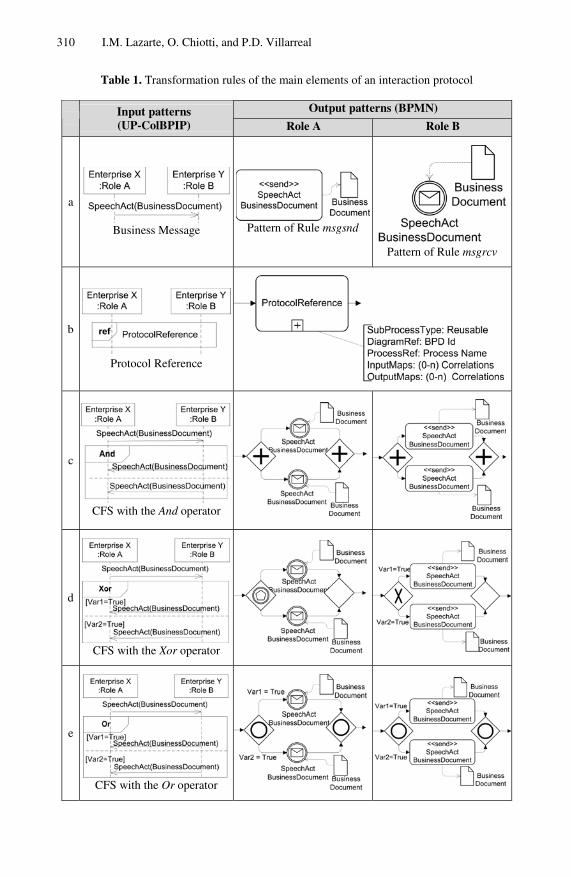
Table 1 shows the transformation rules with their BPMN output patterns for each pro-tocol element according to the partner’s role in the protocol:
• Rule msgrcv (Table 1.a): for each business message received by the role being con-sidered in the transformation, an intermediate event type message is added, except if the message is the first element of the protocol. In this case, the process begins with a start event type message. The intermediate or start event is labeled according to the speech act and business document defined for the message and has an associated data object, which represents the business document involved in the message.
• Rule msgsnd (Table 1.a): for each business message sent by the role being consid-ered, a send task is added, which is labeled according to the speech act and busi-ness document defined in the message and has a data object associated, which represents such business document.
• Rule ref (Table 1.b): for each reference protocol, a reusable sub-process is created to refer to a process defined in another BPD. The name of the sub-process is the same as the protocol it refers to.
• Rule end: for each termination event in a protocol, an end event type terminate labeled Success or Failure is added to the BPD. If this event is in an embedded sub-process, it is modeled by an end event type signal. Then, an intermediate event type signal is attached to the sub-process to catch the signal. The outgoing se-quence flow of this event is connected to an end event type terminate. This ensures that the protocol execution ends when the sub-process returns the control to the main process.
• Rule timeconst: a time constraint is modeled according to the type of protocol ele-ment to which it is attached. (1) If it is a protocol or a CFS, it is mapped into an embedded sub-process with an attached intermediate event type timer. (2) If it is a

Transforming Collaborative Process Models into Interface Process Models 309
message sent by the role or a reference protocol, an intermediate event type timer is attached to the send task or reusable sub-process, respectively. (3) If it is a message received by the role, two mappings are possible. If it is the first received message in a CFS with an Xor or If operator, another gate is added to the exclusive gateway representing the CFS. This gate is connected to an intermediate event type timer indicating the time constraint, unless there is another timer with the same value, in which case the existing one is used. Otherwise, an event-based ex-clusive gateway with two gates is defined, one for the message and another one with an intermediate event type timer to represent the time constraint. In all cases, if the protocol has a CFS Cancel (Rule cancel), which handles time exceptions; the outgoing sequence flow of an intermediate event type timer is connected to the sub-process that handles the exception. If the protocol does not have a CFS cancel, it is connected to an end event type error.
• Rule and (Table 1.c): a CFS And is mapped into a parallel gateway with a gate for each interaction path. If two or more paths do not have an explicit termination, a joining parallel gateway is added to synchronize them.
• Rule xor (Table 1.d): A CFS Xor (either data-based or event-based) is mapped into an event-based exclusive gateway if the role receives messages, or it is mapped into a data-based exclusive gateway if the role sends the messages in the interaction paths. One gate per interaction path is added. If two or more paths do not have an explicit termination event, a merging exclusive gateway is added.
• Rule or (Table 1.e): a CFS Or is mapped into an inclusive gateway with a gate for each interaction path. If two or more paths do not have an explicit termination event, a joining inclusive gateway is added to synchronize them.
• Rule if: a CFS If is mapped into an event-based exclusive gateway if the role re-ceives messages or is mapped into a data-based exclusive gateway if the role sends messages. The gateway has two gates, one for the condition to be satisfied and another one for the else condition. The second gate is generated if the else condition is defined. If it is not, an intermediate event type message is added if the role receives messages, or a send task is added if the role sends messages to indicate that the execution of the protocol should proceed. If two interaction paths do not have an explicit termination event, the gates are joined by a merg-ing exclusive gateway.
• Rule loop: for each CFS with the Loop operator, an embedded sub-process with a Loop Marker is created. The transformation depends on the Loop type. (1) For a “while loop” whose condition is [(0,n), Var1=True], the attribute LoopCondition of the embedded sub-process var1=True and the attribute TestTime with the value Before are settled. (2) For a “repeat until loop” whose condition is [(1, n), Var1=True], the attribute LoopCondition with the value not var1 and the attribute TestTime with the value After are settled.
• Rule except: a CFS Exception is mapped into an embedded sub-process with an attached intermediate event type conditional. The outgoing sequence flow of this event is connected to a sub-process that handles the exception. Both sub-processes are synchronized by a merging exclusive gateway to let the execution continue.
310 I.M. Lazarte, O. Chiotti, and P.D. Villarreal
Table 1. Transformation rules of the main elements of an interaction protocol
Output patterns (BPMN) Input patterns
(UP-ColBPIP) Role A Role B
a
Business Message Pattern of Rule msgsnd
Pattern of Rule msgrcv
b
Protocol Reference
c
CFS with the And operator
d
CFS with the Xor operator
e
CFS with the Or operator

Transforming Collaborative Process Models into Interface Process Models 311
• Rule stop: a CFS Stop is mapped into an embedded sub-process with an attached intermediate event type conditional. The outgoing sequence flow of this event is connected to a sub-process that handles the exception. The outgoing sequence flow of this sub-process is connected to an end event type terminate.
• Rule cancel: a CFS Cancel is mapped into an embedded sub-process. This sub-process is triggered by an intermediate event type timer, if the interaction path of the CFS handles a time constraint, or by an intermediate event type conditional for exceptions related to the protocol logic. The outgoing sequence flow of this sub-process is connected to an end event type terminate.
4 Application of the MDA-Based Method to an Example
The Collaborative Demand Forecast interaction protocol described in section 3 is used for exemplifying the model transformation process aforementioned. From this protocol, the supplier’s interface process (section 4.1) and the customer’s interface process (section 4.2) are generated. These processes are required in order to imple-ment the collaborative process defined by the interaction protocol.
4.1 Generation of the Supplier’s Interface Process
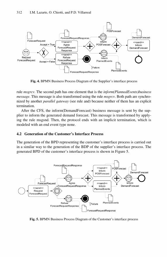
The BPMN BPD representing the generated supplier’s interface process is shown in Figure 4. In the transformation process all protocol elements are analyzed from a sup-plier’s viewpoint. The first protocol element is the request(ForecastRequest) business message, which is received by the supplier. This message is transformed using the rule msgrcv, which consists of creating a start event type message. This event is labeled Re-quest ForecastRequest and is associated with the ForecastRequest data object, which represents the business document interchanged between enterprises.
Then, the CFS with the Xor operator is transformed by applying the rule xor. This rule adds a data-based exclusive gateway with two gates, one for each interaction path. Then, each path is analyzed to determine the pattern to be used in the transfor-mation. The first element of the first path is the agree(ForecastRequestResponse) business message, which is sent to the customer. The message is transformed by the rule msgsnd that generates a send task. This task is labeled Agree ForecastRequestRe-sponse and is associated with the ForecastRequestResponse data object, which repre-sents the exchanged business document. There are no further elements in this path so the other path is analyzed. The first element of the second path is the re-fuse(ForecastRequestResponse) business message. This message is transformed by the rule msgsnd that generates a send task. The next element is a termination event, which is transformed by the rule end. Because one path has an explicit termination, the two gates are not synchronized and the transformation continues along the path which does not have the explicit termination.
The next protocol element is the CFS with the And operator that is transformed by the rule and. This rule adds a parallel gateway with two gates, one for each interaction path. The first path is analyzed and its single element is the inform(POSForecast) business message, which is received by the supplier. This message is transformed by applying the
312 I.M. Lazarte, O. Chiotti, and P.D. Villarreal
Fig. 4. BPMN Business Process Diagram of the Supplier’s interface process
rule msgrcv. The second path has one element that is the inform(PlannedEvents)business message. This message is also transformed using the rule msgrcv. Both path are synchro-nized by another parallel gateway (see rule and) because neither of them has an explicit termination.
After the CFS, the inform(DemandForecast) business message is sent by the sup-plier to inform the generated demand forecast. This message is transformed by apply-ing the rule msgsnd. Then, the protocol ends with an implicit termination, which is modeled with an end event type none.
4.2 Generation of the Customer’s Interface Process
The generation of the BPD representing the customer’s interface process is carried out in a similar way to the generation of the BDP of the supplier’s interface process. The generated BPD of the customer’s interface process is shown in Figure 5.
Fig. 5. BPMN Business Process Diagram of the Customer’s interface process

Transforming Collaborative Process Models into Interface Process Models 313
5 Related Work
There are several approaches that exploit the benefits of model-driven architectures for B2B processes [13]. A method for modeling cross-organizational processes based on the MDA was proposed [3], which supports the mapping of ARIS models of cross-organizational value chains into BPDM models of abstract (interface) processes. These processes are defined in UML2 activity diagrams. However, the proposed ar-chitecture uses a centralized broker to implement and govern B2B interactions. It is different from our approach that encourages the decentralized management of col-laborative processes.
Another MDA-based method was proposed to generate BPEL abstract (interface) processes from UP-ColBPIP interaction protocols [7]. Although this method allows generating BPEL specifications, the addition of private logic to BPEL processes has to be done at a technological level. Instead, in this work we provide an approach to elevate the abstraction level of interface processes so that business analysts can use them to generate integration processes. Then, BPEL specifications can be generated from these models.
Also, an approach was proposed to derive local choreographies (interface proc-esses) from UMM global choreographies to register them in a global repository [14]. A UML Profile is proposed to represent local choreographies. It is not based on a model-driven approach. In addition, in this work we use the BPMN standard language so that enterprises can understand and define interface processes, instead of using a particular language.
Another approach is for checking consistency of predefined interface processes [15]. It is a useful method for bottom-up approaches to determine if these processes are interoperable for building a B2B scenario. Instead, our method promotes a top-down approach. Enterprises agree on an interaction global view and the behavioral constraints of each participant are guaranteed by deriving interface processes from a global interaction model.
6 Conclusions and Future Work
In this work we have proposed an MDA-based method for the automatic generation of the interface process model of each enterprise from a collaborative process model. This method enables enterprises to generate interoperable interface processes and in compliance with the global logic of B2B interactions agreed on collaborative proc-esses. This is guaranteed since the partners’ interface process models are derived from a collaborative process model by applying a top-down MDA-based approach.
The language UP-ColBPIP is used to define the B2B collaboration view among the partners. It encourages the modeling of interaction protocols to represent the behavior of technology-independent collaborative processes. The use of interaction protocols supports the main features of B2B collaborations: global view of the B2B interac-tions, enterprise autonomy, decentralized management, peer-to-peer interactions and negotiations.
In addition, this method increases the abstraction level in the design of the part-ners’ view of a B2B collaboration. The BPMN standard language is used to define

314 I.M. Lazarte, O. Chiotti, and P.D. Villarreal
activity-oriented interface process models. This enables enterprises to understand and focus on the business requirements to fulfill the role they perform in collaborative processes.
Also, it is pretended to integrate this method to the previously proposed MDA-based method for collaborative processes [5, 6, 10], in order to provide a complete methodology that supports the modeling, verification and specification of the business processes required in B2B collaborations.
Finally, the proposed MDA-based transformation process shows that a direct map-ping can be applied to derive BPMN Business Process Diagrams of interface proc-esses from an interaction protocol. No intervention is required by a modeler. For each element of the UP-ColBPIP language used to describe interaction protocols, a BPMN pattern is proposed to represent its behavior from the viewpoint of the role a partner performs in the protocol.
Future work will define the transformation rules in ATL languages and implement these process model transformations in an Eclipse-based tool developed for the mod-eling and verification of collaborative processes [12]. Another work is about the defi-nition of integration processes from interface processes by adding private activity patterns to process or generate the information exchanged between the partners.
References
1. Villarreal, P., Caliusco, M., Zucchini, D., Arredondo, F., Zanel, C., Galli, M.R., Chiotti, O.: Integrated Production Planning and Control in a Collaborative Partner-to-Partner Rela-tionship. In: Sharma, S., Gupta, J. (eds.) Managing E-Business in the 21st Century, pp. 91–110. Heidelberg Press, Australia (2003)
2. Villarreal, P.D., Salomone, E., Chiotti, O.: Transforming Collaborative Business Process Models into Web Services Choreography Specifications. In: Lee, J., Shim, J., Lee, S., Bus-sler, C., Shim, S. (eds.) DEECS 2006. LNCS, vol. 4055, pp. 50–65. Springer, Heidelberg (2006)
3. Bauer, B., Roser, S., Müller, J.: Adaptive Design of Cross-organizational Business Proc-esses using a Model-driven Architecture. In: Wirtschaftsinformatik 2005, pp. 103–121. Physica-Verlag press (2005)
4. Weske, M.: Business Process Management. Concepts, Languages, Architectures. Springer, Heidelberg (2007)
5. Villarreal, P., Salomone, E., Chiotti, O.: Modeling and Specifications of Collaborative Business Processes using a MDA Approach and a UML Profile. In: Rittgen, P. (ed.) Enter-prise Modeling and Computing with UML, pp. 13–45. Idea Group Inc., USA (2007)
6. Villarreal, P.: Method for the Modeling and Specification of Collaborative Business Proc-esses, Ph.D. dissertation. Ceride Press, Santa Fe, Argentina (2005)
7. Villarreal, P., Salomone, E., Chiotti, O.: MDA Approach for Collaborative Business Proc-esses: Generating Technological Solutions based on Web Services Composition. In: 9th Ibero-American Workshop IDEAS, Argentina (2006)
8. OMG. BPMN V1.1 (January 2008), http://www.omg.org/spec/BPMN/1.1/PDF 9. OASIS, Web Services Business Process Execution Language (May 2007),
http://www.oasis-open.org/committees/download.php/23964/ wsbpel-v2.0-primer.htm

Transforming Collaborative Process Models into Interface Process Models 315
10. Villarreal, P., Roa, J., Chiotti, O., Salomone, E.: Aligning the Business Solution with the Technological Solution in the Development of B2B Collaborations. In: CollECTeR Iberoamérica 2007, Argentina (2007)
11. OMG. MDA Guide V1.0.1 (2003), http://www.omg.org/mda 12. Roa, J., Castañeda, V., Villarreal, P., Chiotti, O.: A Tool for Model-Driven Development
of Collaborative Business Processes. In: XXXIV Latin-American Conference on Informat-ics (CLEI 2008), Santa Fe, Argentina (2008)
13. Folmer, E., Bastiaans, J.: Methods for Design of Semantic Message-Based B2B Interac-tions Standards. In: Mertins, K., Ruggaber, R., Popplewell, K., Xu, X. (eds.) Enterprise In-teroperability III, pp. 183–194. Springer, London (2008)
14. Hofreiter, B.: Registering UML Models for Global and Local Choreographies. In: 10th In-ternational Conference on Electronic Commerce. ACM, vol. 342, Art. No. 37, ACM Press, New York (2008)
15. Decker, G., Weske, M.: Behavioral Consistency for B2B Process Integration. In: Krogstie, J., Opdahl, A., Sindre, G. (eds.) CAiSE 2007 and WES 2007. LNCS, vol. 4495, pp. 81–95. Springer, Heidelberg (2007)