TRANSFORMER LOSSES FOR THE MAXsys Elite METERS B … · meter to continue registering Kwh, Kvarh...
25
TRANSFORMER LOSSES FOR ELITE METERS DATA FLOW, CALCULATION, SET-UP & TESTING TRANSFORMER LOSSES Transformer losses are calculated (not measured) within the Elite meter. The losses are calculated using measured voltage and current. This allows the meter to continue registering Kwh, Kvarh and Kvah (unaffected by compensation). This means the meters measurement circuit is unaffected by the compensation allowing both the measured values and the compensated values to be displayed at the same time. The meter retains its uncompensated values along with copper losses, iron losses and the compensated values. This allows all compensation variables to be available for the customers to use based on his needs. The same process is used in all versions of the firmware, both single and multiple level versions. The standard multiple level firmware, will compensate across three sets of transformers or lines, or a combination of both. Each of the three levels of compensation well allow up to six sets of constants which can be controlled with logic from external contacts or with communications commands. LINE AND TRANSMISSION LOSSES The firmware versions have the ability to perform line losses (Resistance ohms) and transmission line losses (Resistance in ohms, Reactance in ohms and Charging Vars in Kvar). The firmware allows for multiple sets of constants, which can be changed based on changes in the transmission systems. The change can be control from external inputs and over communications as well as using the internal logic. CALCULATIONS KWH The calculation of no-load (Iron) losses is based on the ratio of the voltages being measured and the rated voltage squared and the results multiplied by the no-load value from the data sheet. The Elite meter has what is referred to as an Iron constant (KWFe). This constant is multiplied by the voltage
Transcript of TRANSFORMER LOSSES FOR THE MAXsys Elite METERS B … · meter to continue registering Kwh, Kvarh...
TRANSFORMER LOSSES FOR ELITE METERS DATA FLOW, CALCULATION, SET-UP & TESTING
TRANSFORMER LOSSES Transformer losses are calculated (not measured) within the Elite meter. The losses are calculated using measured voltage and current. This allows the meter to continue registering Kwh, Kvarh and Kvah (unaffected by compensation). This means the meters measurement circuit is unaffected by the compensation allowing both the measured values and the compensated values to be displayed at the same time. The meter retains its uncompensated values along with copper losses, iron losses and the compensated values. This allows all compensation variables to be available for the customers to use based on his needs. The same process is used in all versions of the firmware, both single and multiple level versions. The standard multiple level firmware, will compensate across three sets of transformers or lines, or a combination of both. Each of the three levels of compensation well allow up to six sets of constants which can be controlled with logic from external contacts or with communications commands. LINE AND TRANSMISSION LOSSES The firmware versions have the ability to perform line losses (Resistance ohms) and transmission line losses (Resistance in ohms, Reactance in ohms and Charging Vars in Kvar). The firmware allows for multiple sets of constants, which can be changed based on changes in the transmission systems. The change can be control from external inputs and over communications as well as using the internal logic. CALCULATIONS KWH The calculation of no-load (Iron) losses is based on the ratio of the voltages being measured and the rated voltage squared and the results multiplied by the no-load value from the data sheet. The Elite meter has what is referred to as an Iron constant (KWFe). This constant is multiplied by the voltage

squared and the results will equal the KW losses of the transformer due to voltage (No-Load or Iron Losses). Transformer Data: 4160-volt, 3000 KVA, Delta connected transformer with Iron Losses of 9200 watts, Copper Losses of 21720 watts, Impedance of 6.25%, exciting current of 1.54% and an actual measured voltage of 4020 volts. The example below shows the no-load (Iron) losses will change only with changes in voltage, not current or power factor. Based on the transformer test sheet, the no-load (Iron) losses of 9200 watts was at rated transformer voltage. Iron Loss calculations at 4160 and 4020 Volts. Example: Calculated loss @ 4160 volts (4160/4160)^2 x 9200 = 9200.0 watts MAXsys calculation @ 4160 volts (4160^2) x 2 x 2.6581E-7 = 9.200 KW Number of voltages available within the meter KWHFe constant used by the meter Calculated loss @ 4020 volts (4020/4160)^2 x 9200 = 8591.1 watts MAXsys calculation @ 4020 volts (4020^2) x 2 x 2.6581E-7 = 8.5911 KW Number of voltages available within the meter KWFe constant used by the meter The calculation of load (Copper) losses are based on the ratio of the current being measured and the rated full load current squared and the results multiplied by load (copper) losses from the data sheet. The MAXsys meter has what is referred to as a Copper constant (KWCu). This constant will be multiplied by the current squared, and the results will equal the KW losses of the transformer due to the current load (Copper) losses. The example below shows the Load (Copper) Losses will change only with changes in current, not voltage or power factor. The first requirement is to calculate the full load transformer current before the Load (Copper) Losses

can be calculated. Based on the transformer test sheet, the Load (Copper) Losses are 21720 watts at full transformer rated current. The full load line current on the low side of the transformer (4160 volts) is calculated as follows based on the data sheet. 3000Kva x 1000/(4160Volts x 1.732) = 416.35 Amps. Copper loss calculation at 416.35 and 200 Amps. Example: Calculated loss @ 416.35 Amps (416.35/416.35)^2 x 21720 = 21720.0 watts MAXsys calculation @ 416.35 Amps (416.35^2) x 2 x 6.26463E-5 = 21.72 KW Number of currents available within the meter KWHCu constant used by the meter Calculated loss @ 200.0 Amps (200.00/416.35)^2 x 21720 = 5011.9 watts MAXsys calculation @ 200.0 Amps (200.00^2) x 2 x 6.26463E-5 = 5.011 KW Number of currents available within the meter KWHCu constant used by the meter CALCULATIONS KVARH The calculation of Vars of Iron Loss is based on the ratio of the voltages being measured and the rated voltage being taken to the fourth power and the results are multiplied by theVars Iron Loss from the data sheet. The MAXsys meter has what is referred to as an Iron constant (KVFe). This KVFe constant will be multiplied by the voltage to the fourth power and the results will equal the Kvar losses of the transformer due to voltage (Vars of Iron Loss). The examples which follow are based on the following transformer and load data. The Vars of Iron Loss of a 4160-volt, 3000 KVA, Delta connected transformer with Iron Losses of 9200 watts, Copper Losses of 21720 watts,
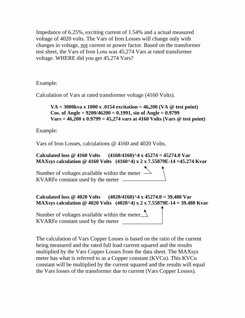
Impedance of 6.25%, exciting current of 1.54% and a actual measured voltage of 4020 volts. The Vars of Iron Losses will change only with changes in voltage, not current or power factor. Based on the transformer test sheet, the Vars of Iron Loss was 45,274 Vars at rated transformer voltage. WHERE did you get 45,274 Vars? Example: Calculation of Vars at rated transformer voltage (4160 Volts). VA = 3000kva x 1000 x .0154 excitation = 46,200 (VA @ test point) Cos. of Angle = 9200/46200 = 0.1991, sin of Angle = 0.9799 Vars = 46,200 x 0.9799 = 45,274 vars at 4160 Volts (Vars @ test point) Example: Vars of Iron Losses, calculations @ 4160 and 4020 Volts. Calculated loss @ 4160 Volts (4160/4160)^4 x 45274 = 45274.0 Var MAXsys calculation @ 4160 Volts (4160^4) x 2 x 7.55879E-14 =45.274 Kvar Number of voltages available within the meter KVARFe constant used by the meter Calculated loss @ 4020 Volts (4020/4160)^4 x 45274.0 = 39,480 Var MAXsys calculation @ 4020 Volts (4020^4) x 2 x 7.55879E-14 = 39.480 Kvar Number of voltages available within the meter KVARFe constant used by the meter The calculation of Vars Copper Losses is based on the ratio of the current being measured and the rated full load current squared and the results multiplied by the Vars Copper Losses from the data sheet. The MAXsys meter has what is referred to as a Copper constant (KVCu). This KVCu constant will be multiplied by the current squared and the results will equal the Vars losses of the transformer due to current (Vars Copper Losses).

The examples which follow are based on the following transformer and load data. The Vars Copper Loss of a 4160-volt, 3000 KVA, Delta connected transformer with Copper Losses of 21,720 watts, Iron Losses of 9,200 watts, Impedance of 6.25% and 1.54% exciting current. The Vars copper losses will change only with changes in current, not voltage or power factor. The first requirement is to calculate the full load transformer current before the Vars copper losses can be calculated. Based on the transformer test sheet, the Vars copper loss of 186,237 Vars was at rated full transformer current. WHERE did you get 186,237 Vars? Example: The full load line current on the low side (metering side) of the transformer (4160 volts). 3000Kva x 1000/(4160Volts x 1.732) = 416.35 Amps. Example: The calculation of Vars at full rated transformer current (416.35 Amps). VA = 3000kva x 1000 x 0.0625 impedance = 187,500 (VA @ test point) Cos. of Angle = 21727/187500 = 0.11854, sin of Angle = 0.99326 Vars = 187,500 x 0.99326 = 186,237 (Vars @ transformer full load current) Vars of Copper Losses, calculations @ 416.35 and 200 Amps. Calculated loss @ 416.35 Amps (416.35/416.35)^2 x 186,237 = 186,237.0 Var MAXsys calculation @ 416.35 Amps (416.35^2) x 2 x 5.371E-4(KVCu) =186.237 Kvar Number of currents available within the meter KVARCu constant used by the meter
Calculated loss @ 200.0 Amps (200/416.35)^2 x 186,237 = 42,974.0 Var MAXsys calculation @ 200.0 Amps (200^2) x 2 x 5.371E-4(KVCu) = 42.974 Kvar Number of currents available within the meter KVARCu constant used by the meter

DATA FLOW
Voltage
Current
DSP
Kwh
Kvar
C A L C U L A T I O N
Kwh Cu
Kwh Fe
Kvar Cu
Kvar Fe
Totalizer Compensated Kwh ( CKwh)
Totalizer Compensated Kvarh ( CKvarh)
CKvarh
CKwh
Calibration LED Calibration Relay Displays Recorders Relays Analogs
Displays Recorders Relays Analogs
Other displays are created with the above data to meet special customer requirements as well as testing. Kwh Copper Loss Kwh Iron Loss Kvarh Copper Loss Kvarh Iron Loss % KwhCu Comes from a transform (KwhCu / Kwh) % KwhFe Comes from a transform (KwhFe / Kwh) % KvarhCu Comes from a transform (KvarhCu / Kvarh) % KvarhFe Comes from a transform (KvarhFe / Kvarh) % Ckwh Accuracy with Losses Comes from a transform (CKwh/Kwh) % Ckvarh Accuracy with Losses Comes from a transform (Ckvarh/Kvarh)

KOMPENSATORS The Elite Meter can do three sets of losses and each set can have six sets of Iron and Copper constants. Each of the compensators will allow the user to bring in four signed Kwh and Kvarh values (which can be netted) along with voltages and currents. The Kompensator can calculated current if it is un-measured, this feature would be used if power values are being netted or the losses are downstream other side of the power transformer or downstream of transmission lines. In the standard configuration (default files): The inputs for Kompensator 1 come from two Totalizers (+/- Kwh) and (+/- Kvarh) along with the voltages and currents. The outputs ( +/- Compensated Kwh and Kvarh along with Compensated Voltage feeds the inputs of Kompensator 2 and the same outputs form Kompensator 2 feeds the inputs of Kompensator 3. The outputs of Kompensator 3 are used for compensated values in the program. The diagram below shows how the Kompensators can be connected together. The default firmware supports 3 Kompensators. The reason for “Compensators” being spelled with a “K” is the meter already had a “C” bus when the multi-level TLC was developed. Therefore “Kompensator” and the outputs are “K” bus.
KWH
KVARH
V2H
I2H
KWH
KVARH
V2H
I2H
I BUSS
T BUSS
K BUSS
X BUSS
COMPENSATOR1
COMPENSATOR2
COMPENSATOR“N”
K1
-K20
K21
-K
40
MULTIPLE COMPENSATION BLOCKS
� COMPANY CONFIDENTIAL
Naming (numbering) of Outputs for Kompensator 1: K1- Compensated Kwh Delivered K2- Compensated Kwh Received K3- Compensated +/- Kwh

K4- Compensated Kvarh Q3 K5- Compensated Kvarh Q2 K6- Compensated Kvarh Q4 K7- Compensated Kvarh Q1 K8- Compensated Kvarh Received K9- Compensated Kvarh Delivered K10- Compensated +/- Kvarh K11- V2H corrected K12- V2H Filtered K13- I2H Filtered K14- Compensated Kvah K15- Kwh Copper Losses K16- Kvarh Copper Losses K17- Kwh Iron Losses K18- Kvarh Iron Losses volts squared (Line Losses) K19- Kvarh Iron Losses volts to the 4th (Transformer Losses) K20- Compensated V2H Kompensator 2 has the same outputs however they are numbered K21-K40. Kompensator 3 has the same outputs however they are numbered K41-K60.

The following diagram shows more details of the Kompensator’s structure.
KWH TOTALIZER
KVARH TOTALIZER
V2H TOTALIZER
I2H TOTALIZER
KWHINPUTS
KVARHINPUTS
V2HINPUTS
(3 LINES)
I2HINPUTS
(3 LINES)
SENSE&
RELAYS
CONSTANT SELECTION
CONSTANT SET 1
CONSTANT SET 2
CONSTANT SET “N”
COMP KWH
COMP KVARH
COMP V H
LOSSES
LOSSCALCULATIONS
K BUSSOUTPUTS(20 LINES)
COMPENSATION BLOCK DETAIL
�
2
The diagram above shows the 4 summations for Kwh, Kvarh, V2H and I2H along with the sense inputs that are used to control which set of (6) constants that will be used for the calculations. The sense inputs could be connected to line status relays and the line loss calculations would change as lines were switched in and out.
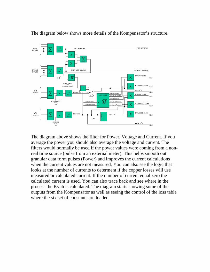
The diagram below shows more details of the Kompensator’s structure.
KWH FE LOSS
FILT I H
KVARH CU LOSS
KWH CU LOSS
2
KVARH FE LOSS2
KVARH FE LOSS4
KWHINPUTS
V HINPUTS
I HINPUTS
LPFILT
LPFILT
/
/
LPFILT
LPFILT
106
FILT NET KVARH
FILT NET KWH
FILT V H
/
TIME
FILT V H
KWH CU CONST
KVARH CU CONST
KWH FE CONST
KVARH FE CONST
KVARH FE CONST
# OF I HINPUT
X
X
X
X
X
LOSS TABLE
FILT NET KWH
X
X
XX/
S0
S1
IF TEST THEN 1ELSE
CT
IF TEST 1ELSE
PT2
2
2
FILT I H (IN)2
IF TEST THEN 1ELSE
(ENERGY NORM)2
2
FILT NET KVARH
4
FILT V H2
2
4
2
2
KVARHINPUTS
= = 0
> 0
K15
K16
K13
K17
K18
K12
TABLE 3 SENSE
TABLE 3 OUTPUT
K19
XX/
�
The diagram above shows the filter for Power, Voltage and Current. If you average the power you should also average the voltage and current. The filters would normally be used if the power values were coming from a non-real time source (pulse from an external meter). This helps smooth out granular data form pulses (Power) and improves the current calculations when the current values are not measured. You can also see the logic that looks at the number of currents to determent if the copper losses will use measured or calculated current. If the number of current equal zero the calculated current is used. You can also trace back and see where in the process the Kvah is calculated. The diagram starts showing some of the outputs from the Kompensator as well as seeing the control of the loss table where the six set of constants are loaded.

The diagram below shows more details of the Kompensator’s structure.
X
X
X
X
�
SEL
BUCKET SIZE
KWH REC COMP
KWH DEL COMP
KWH NET DEL COMP
KVARH Q3 COMP
KVARH Q2 COMP
KVARH Q4 COMP
KVARH Q1 COMP
KVARH REC COMP
KVARH DEL COMP
KVAH COMP
KVARH NET DEL COMP
AVG V H COMP2
CORRECTED AVG. V H2
(IF KWH NEG) K1
(IF KWH POS) K2
(SIGNED KWH) K3
(-KWH, -KVARH) K4
(-KWH, +KVARH) K5
(+KWH, -KVARH) K6
(+KWH, +KVARH) K7
(IF KVARH NEG) K8
(IF KVARH POS) K9
(SIGNED KVARH) K10
K14
K20
K11
FILT NET KWH
KWH FE LOSS
KWH CU LOSS
FILT NET KVARH
KVARH FE LOSS
KVARH FE LOSS
KVARH CU LOSS
2
4
FILT V H2
# OF V H INPUTS2
IF TEST THEN 1, ELSE PT2
XFORMER RATIO (LOSS TABLE)
(COMP KVAH)2
(KVAH’)2
X
X
X/
/
X
X
X
ABS
ABS
ABS
-
+
-,-
-,+
+,-
+,+
-
+
SEL1
SEL0
SEL
The diagram above shows the buckets which are used if the Power values are non-real time (pulses). This bucket allows the losses to accumulate up to the bucket size. If there is no measure power over the time it takes for the bucket to fill the losses will be applied to zero power values. This diagram also shows the balance of the Kompensator outputs.
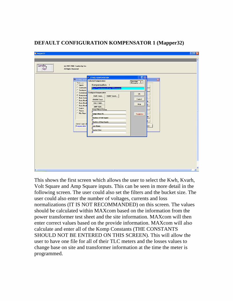
DEFAULT CONFIGURATION KOMPENSATOR 1 (Mapper32)
This shows the first screen which allows the user to select the Kwh, Kvarh, Volt Square and Amp Square inputs. This can be seen in more detail in the following screen. The user could also set the filters and the bucket size. The user could also enter the number of voltages, currents and loss normalizations (IT IS NOT RECOMMANDED) on this screen. The values should be calculated within MAXcom based on the information from the power transformer test sheet and the site information. MAXcom will then enter correct values based on the provide information. MAXcom will also calculate and enter all of the Komp Constants (THE CONSTANTS SHOULD NOT BE ENTERED ON THIS SCREEN). This will allow the user to have one file for all of their TLC meters and the losses values to change base on site and transformer information at the time the meter is programmed.

The next two screen shots show the set-up of the power inputs and the ability to add or subtract the value which will allow the user to net loads before calculating the losses. If the user is netting power values they will need to use calculate current (set number of currents to zero) and the inputs to “Unknown/Not Used”.
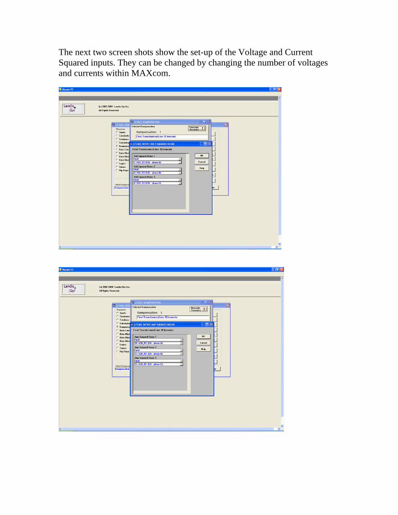
The next two screen shots show the set-up of the Voltage and Current Squared inputs. They can be changed by changing the number of voltages and currents within MAXcom.
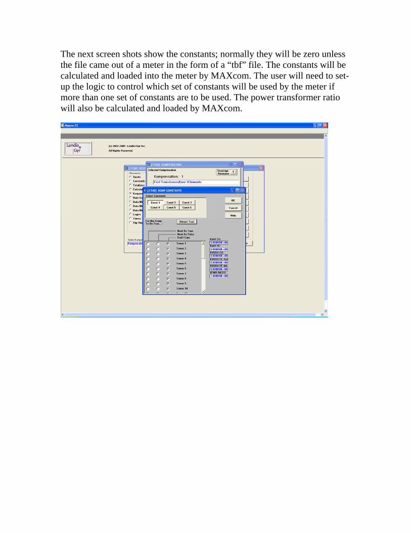
The next screen shots show the constants; normally they will be zero unless the file came out of a meter in the form of a “tbf” file. The constants will be calculated and loaded into the meter by MAXcom. The user will need to set-up the logic to control which set of constants will be used by the meter if more than one set of constants are to be used. The power transformer ratio will also be calculated and loaded by MAXcom.

PROGRAMMING LOSSES INTO THE METER The losses constants are normally calculated and loaded into the meter by MAXcom. When entering the information into MAXcom it is recommend the user enter the values using the “Transformer Loss Calculations” method. If the user must use the “Transformer Loss Coefficients (percents)” and they are programming a form 35 meter 3-phase 3-wire they most know if the percents were based on a 3-phase or single phase (series) calculations. If the user is programming a form 36 meter 3-phase 4-wire the percents most of been calculated based on 3-phase calculations NOT single phase (series). MAXcom CONFIGURATION The first requirement when you are going to do Transformer Losses is select the TLC option in the ‘Program Profile Download List”. The screen below shows “Transformer Loss Calculations” has been selected. By making this selection the program will require the user to enter information on both the power transformer and the metering (site) installation.
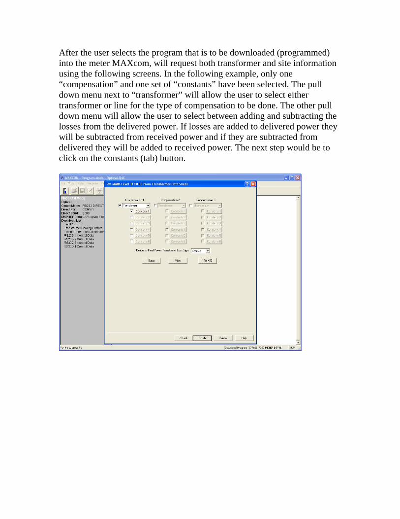
After the user selects the program that is to be downloaded (programmed) into the meter MAXcom, will request both transformer and site information using the following screens. In the following example, only one “compensation” and one set of “constants” have been selected. The pull down menu next to “transformer” will allow the user to select either transformer or line for the type of compensation to be done. The other pull down menu will allow the user to select between adding and subtracting the losses from the delivered power. If losses are added to delivered power they will be subtracted from received power and if they are subtracted from delivered they will be added to received power. The next step would be to click on the constants (tab) button.

After clicking on “constants” the user will get the next screen. The “Meter Side Wiring:” pull down menu will allow the customer to select “Delta, Wye, Open Delta, Single Phase-One Element, 4-wire Delta or Single Phase-two Element” this is the way the transformer is being metered. The “Transformer Type:” pull down menu will allow the customer to select their transform bank configuration. The selections are “one single 3-phase Transformer” or a “bank of single phase Transformers”. If a “bank of Single Phase Transformer is selected the user will then be able to enter information for each of the transformers. If the installation requires uses of a form 36 meter the user would check the box for the form 36S/6A. The following information is base on a meter being wired as a “Wye” meter and one 3-phase transformer.
Site Information Potential Transformer Turns Ratio: 7200 to 120 VT would be 60 Current Transformer Turns Ratio: 1200 to 5 CT would be 240
Transformer Information Power Transformer Test Voltage: This is the voltage that was applied to the transformer for the “NO LOAD” (Iron) test. The information comes from the transformer data sheet. This IS NOT the VT voltage. Example: The no load data was taken with 7620 volts applied to the transformer. Line to Neutral Test Voltage Opposite Side: This name will change to Line to Line if the “meter side wiring” is changed to Delta. This information is only required if the next Kompensator is being used. If the second Kompensator is not being used enter the same value that was used for the “transformer test voltage”. Example: 7620 Volts Full Load KVA: This is the KVA that was applied for the Load Loss (Copper) test from the transformer data sheet. Example: 15000 Kva No Load Percent Excitation Current: This value comes from the transformer data sheet. Note, the full load Kva time the percent excitation current must be larger than the “No Load Losses” watts. Example: 0.12% No Load Watts Loss: This value comes from the transformer data sheet. Some data sheets reports this value in Kw, however the value must be entered in Watts. Example: 13694 Watts Full Load Percent Impedance: This value comes from the transformer data sheet. Note, the full load Kva time the percent excitation current must be larger than the “Load Losses” watts. Example: 8.12%
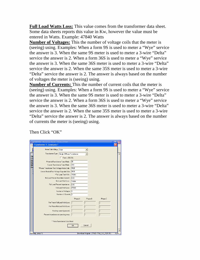
Full Load Watts Loss: This value comes from the transformer data sheet. Some data sheets reports this value in Kw, however the value must be entered in Watts. Example: 47840 Watts Number of Voltages: This the number of voltage coils that the meter is (seeing) using. Examples: When a form 9S is used to meter a “Wye” service the answer is 3. When the same 9S meter is used to meter a 3-wire “Delta” service the answer is 2. When a form 36S is used to meter a “Wye” service the answer is 3. When the same 36S meter is used to meter a 3-wire “Delta” service the answer is 2. When the same 35S meter is used to meter a 3-wire “Delta” service the answer is 2. The answer is always based on the number of voltages the meter is (seeing) using. Number of Currents: This the number of current coils that the meter is (seeing) using. Examples: When a form 9S is used to meter a “Wye” service the answer is 3. When the same 9S meter is used to meter a 3-wire “Delta” service the answer is 2. When a form 36S is used to meter a “Wye” service the answer is 3. When the same 36S meter is used to meter a 3-wire “Delta” service the answer is 2. When the same 35S meter is used to meter a 3-wire “Delta” service the answer is 2. The answer is always based on the number of currents the meter is (seeing) using. Then Click “OK”

After clicking “OK” you will be returned to the following screen.
You can click “View” and review the information that you entered. After reviewing the information click “Cancel” to be returned to the previous display.

Before the user can view the data (table 52) that will be entered into the meter by MAXcom, they must click “Save”. Then the user can click “View 52” and see the data that will be placed in the meter.
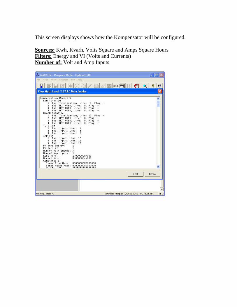
This screen displays shows how the Kompensator will be configured. Sources: Kwh, Kvarh, Volts Square and Amps Square Hours Filters: Energy and VI (Volts and Currents) Number of: Volt and Amp Inputs
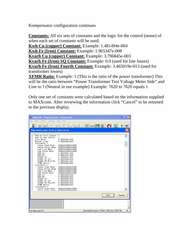
Kompensator configuration continues Constants: All six sets of constants and the logic for the control (sense) of when each set of constants will be used. Kwh Cu (copper) Constant: Example: 1.481494e-004 Kwh Fe (Iron) Constant: Example: 1.965347e-008 Kvarh Cu (copper) Constant: Example: 3.796845e-003 Kvarh Fe (Iron) SQ Constant: Example: 0.0 (used for line losses) Kvarh Fe (Iron) Fourth Constant: Example: 3.465019e-013 (used for transformer losses) XFMR Ratio: Example: 1 (This is the ratio of the power transformer) This will be the ratio between “Power Transformer Test Voltage Meter Side” and Line to ? (Neutral in our example) Example: 7620 to 7620 equals 1 Only one set of constants were calculated based on the information supplied to MAXcom. After reviewing the information click “Cancel” to be returned to the previous display.

When the user is satisfied and clicks “Finish”, the Kompensator will be configured and the loss constants will be load into the meter.
TESTING Kwh & Kvarh Testing the accuracy of the meter’s Kwh and Kvarh should be done using the LEDs (see Elite Accuracy Testing) in the optical port on the face of the meter or by setting output relays to calibrated Kwh & Kvarh. Note: The Kwh & Kvarh values are calculated from the calibrated voltage, current inputs of the meter. Compensated Kwh & Kvarh Testing the accuracy of the meter’s compensated Kwh and Kvarh should be done using the display in the normal or test mode as well as using the LEDs (see Elite Accuracy Testing) in the optical port. The output relays should not normally be used to test compensated values because of the amount of time required. The following displays can be used: Kwh Kvarh Compensated Kwh Compensated Kvarh (With these four displays you can calculate the losses) % Kwh Copper % Kwh Iron % Kvarh Copper % Kvarh Iron % Compensated Kwh with losses % Compensated Kvarh with losses (With these displays you have the percent correction displayed in real time) Note: All of the percent values are referenced to the tested Kwh & Kvarh values within the meter. The copper and Iron losses are calculated from the same voltages and currents used for the Kwk & Kvarh values in the meter. The data flow diagram shows the how all of the compensated values are referenced back the measured un-compensated Kwh & Kvarh values within the meter.