
Transformer Construction - Bapatla Engineering...
20
Bapatla Engineering College: Bapatla (AUTONOMOUS) EEE Department Class: 2/4 EEE SCHEME OF VALUATION Date: 16/06/2016 Sub. Code: 14EE406 TRANSFORMER &INDUCTION MOTOR Max.Marks:60M a) Copper losses ( I²R)depends on Current which passing through transformer winding while Iron Losses or Core Losses or Insulation Losses depends on Voltage. So the Cu Losses depend on the rating current of the load so the load type will determine the powerfactor P.F , Thats why the rating of Transformer in kVA,Not in kW. b) An ideal transformer is an imaginary transformer which does not have any loss in it, means no core losses, copper losses and any other losses in transformer. Efficiency of this transformer is considered as 100%. c) Copper Losses = Variable Losses. d) To give a supply to an existing two phase system from a three phase supply.To supply two phase furnace transformers from a three phase source. e) tertiary winding is provided for ELIMINATION OF HARMONICS f) K times g) 750 RPM h) It is common to express the slip as the ratio between the shaft rotation speed and the synchronous magnetic field speed. S = (n s - n a ) 100% / n s i) Noload and Blocked Rotor test j) Rotor resistance starter k) Adding external resistance in the rotor circuit,Cascade control,Injecting slip frequency voltage into the rotor circuit l) RMF UNIT-I 2. a) Transformer Construction [6M] For the simple construction of a transformer, you must need two coils having mutual inductance and a laminated steel core. The two coils are insulated from each other and from the steel core. The device will also need some suitable container for the assembled core and windings, a medium with which the core and its windings from its container can be insulated. In order to insulate and to bring out the terminals of the winding from the tank, apt bushings that are made from either porcelain or capacitor type must be used. 1. Core- Type Transformer (Comment 3m) The coils used for this transformer are form-wound and are of cylindrical type. Such a type of transformer can be applicable for small sized and large sized transformers. In the small sized type, the core will be rectangular in shape and the coils used are cylindrical. You can see that the round or cylindrical coils are wound in such a way as to fit over a cruciform core section. In the case of circular cylindrical coils, they have a fair advantage of having good mechanical strength. The cylindrical coils will have different layers and each layer will be insulated from the other with the help of materials like paper, cloth, micarta board and so on. The general arrangement of the core-type transformer with respect to the core is shown below. Both low-voltage (LV) and high voltage (HV) windings are shown. The low voltage windings are placed nearer to the core as it is the easiest to insulate. The effective core area of the transformer can be reduced with the use of laminations and insulation
Transcript of Transformer Construction - Bapatla Engineering...

Bapatla Engineering College: Bapatla (AUTONOMOUS) EEE Department
Class: 2/4 EEE SCHEME OF VALUATION Date: 16/06/2016 Sub. Code: 14EE406 TRANSFORMER &INDUCTION MOTOR Max.Marks:60M
a) Copper losses ( I²R)depends on Current which passing through transformer winding while Iron Losses or Core
Losses or Insulation Losses depends on Voltage. So the Cu Losses depend on the rating current of the load so the load type will determine the powerfactor P.F , Thats why the rating of Transformer in kVA,Not in kW.
b) An ideal transformer is an imaginary transformer which does not have any loss in it, means no core losses, copper losses and any other losses in transformer. Efficiency of this transformer is considered as 100%.
c) Copper Losses = Variable Losses. d) To give a supply to an existing two phase system from a three phase supply.To supply two phase furnace
transformers from a three phase source. e) tertiary winding is provided for ELIMINATION OF HARMONICS
f) K times
g) 750 RPM
h) It is common to express the slip as the ratio between the shaft rotation speed and the synchronous magnetic field
speed. S = (ns - na) 100% / ns
i) Noload and Blocked Rotor test
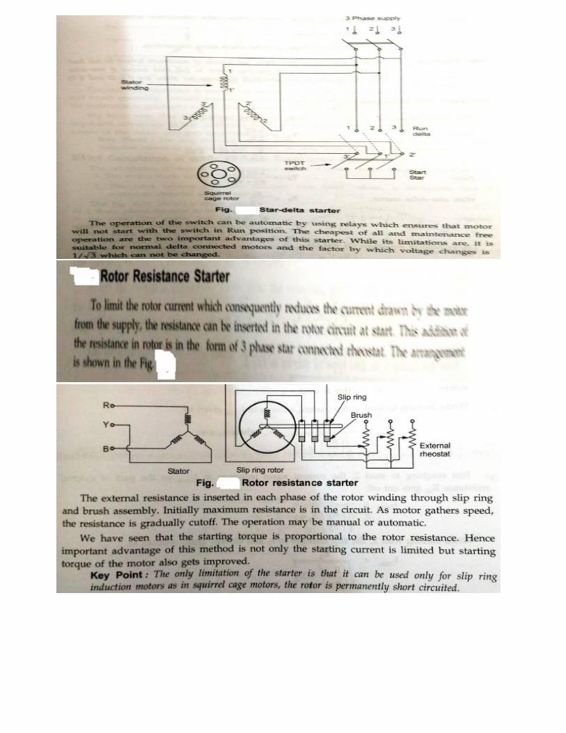
j) Rotor resistance starter
k) Adding external resistance in the rotor circuit,Cascade control,Injecting slip frequency voltage into the rotor circuit
l) RMF
UNIT-I
2. a) Transformer Construction [6M] For the simple construction of a transformer, you must need two coils having mutual inductance and a laminated steel core. The two coils are insulated from each other and from the steel core. The device will also need some suitable container for the assembled core and windings, a medium with which the core and its windings from its container can be insulated. In order to insulate and to bring out the terminals of the winding from the tank, apt bushings that are made from either porcelain or capacitor type must be used.
1. Core- Type Transformer (Comment 3m) The coils used for this transformer are form-wound and are of cylindrical type. Such a type of transformer can be applicable for small sized and large sized transformers. In the small sized type, the core will be rectangular in shape and the coils used are cylindrical. You can see that the round or cylindrical coils are wound in such a way as to fit over a cruciform core section. In the case of circular cylindrical coils, they have a fair advantage of having good mechanical strength. The cylindrical coils will have different layers and each layer will be insulated from the other with the help of materials like paper, cloth, micarta board and so on. The general arrangement of the core-type transformer with respect to the core is shown below. Both low-voltage (LV) and high voltage (HV) windings are shown. The low voltage windings are placed nearer to the core as it is the easiest to insulate. The effective core area of the transformer can be reduced with the use of laminations and insulation

1.
2. Shell-Type Transformer (Comment 3m) The coils are form-wound but are multi layer disc type usually wound in the form of pancakes. Paper is used to insulate the different layers of the multi-layer discs. The whole winding consists of discs stacked with insulation spaces between the coils. These insulation spaces form the horizontal cooling and insulating ducts. Such a transformer may have the shape of a simple rectangle or may also have a distributed form. Both designs are shown in the figure below:

2 b) E.M.F Equation of a Transformer [6M]
Let,
NA = Number of turns in primary, NB = Number of turns in secondary Ømax = Maximum flux in the core in webers = Bmax X A f = Frequency of alternating current input in hertz (HZ) As shown in figure above, the core flux increases from its zero value to maximum value Ømax in one quarter of the cycle , that is in ¼ frequency second. Therefore, average rate of change of flux = Ømax/ ¼ f = 4f ØmaxWb/s Now, rate of change of flux per turn means induced electro motive force in volts. Therefore, average electro-motive force induced/turn = 4f Ømaxvolt If flux Ø varies sinusoidally, then r.m.s value of induced e.m.f is obtained by multiplying the average value with form factor. Form Factor = r.m.s. value/average value = 1.11 Therefore, r.m.s value of e.m.f/turn = 1.11 X 4f Ømax = 4.44f Ømax
Now, r.m.s value of induced e.m.f in the whole of primary winding = (induced e.m.f./turn) X Number of primary turns Therefore, EA = 4.44f NAØmax = 4.44fNABmA Similarly, r.m.s value of induced e.m.f in secondary is EB = 4.44f NB Ømax = 4.44fNBBmA
In an ideal transformer on no load,
VA = EA and VB = EB , where VB is the terminal voltage
(OR)

3.a) [5M] Consider a transformer supplying the load as shown in the Fig. 1.
Fig. 1 The various transformer parameters are, R1 = Primary winding resistance, X1 = Primary leakage reactance R2 = Secondary winding resistance, X2 = Secondary leakage reactance ZL = Load impedance, I1= Primary current I2 = Secondary current = IL = Load current now Ī1 = Īo + Ī2', where Io = No load current I2'= Load component of current decided by the load = K I2 where K is transformer component The primary voltage V1 has now three components, 1. -E1, the induced e.m.f. which opposes V1 2. I1 R1, the drop across the resistance, in phase with I1 3. I1 X1, the drop across the reactance, leading I1 by 90o
The secondary induced e.m.f. has also three components, 1. V2, the terminal voltage across the load 2. I2 R2, the drop across the resistance, in phase with I2 3. I2 X2, the drop across the reactance, leading I2 by 90o
As load power factor is lagging cosΦ2, the current I2 lags V2 by angle Φ2. So only changes in drawing the phasor diagram is to draw I2 lagging V2 by Φ2 in step 5 discussed earlier. Accordingly direction of I2 R2, I2 X2, I2', I1, I1 R1 and I1X1 will change. Remember that whatever may be the power factor of load, I2X2 leads I2 by 90o and I1X1 leads I1 by 90o.

3.b) [7M]
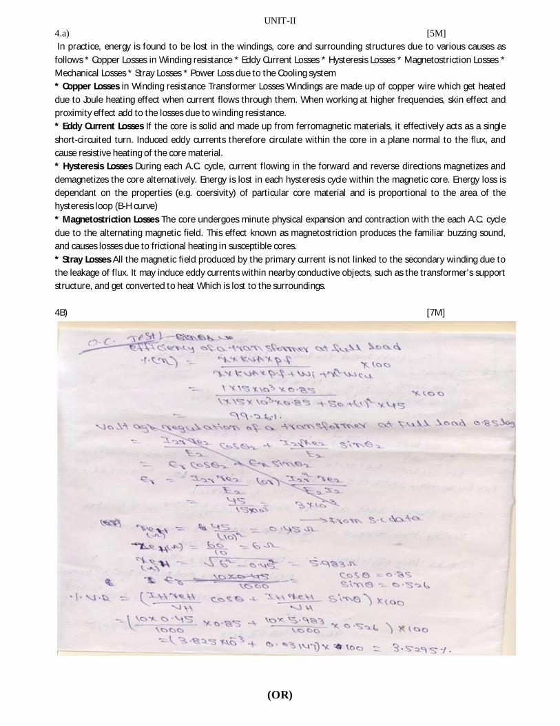
UNIT-II 4.a) [5M] In practice, energy is found to be lost in the windings, core and surrounding structures due to various causes as follows * Copper Losses in Winding resistance * Eddy Current Losses * Hysteresis Losses * Magnetostriction Losses * Mechanical Losses * Stray Losses * Power Loss due to the Cooling system * Copper Losses in Winding resistance Transformer Losses Windings are made up of copper wire which get heated due to Joule heating effect when current flows through them. When working at higher frequencies, skin effect and proximity effect add to the losses due to winding resistance. * Eddy Current Losses If the core is solid and made up from ferromagnetic materials, it effectively acts as a single
short-circuited turn. Induced eddy currents therefore circulate within the core in a plane normal to the flux, and cause resistive heating of the core material. * Hysteresis Losses During each A.C. cycle, current flowing in the forward and reverse directions magnetizes and demagnetizes the core alternatively. Energy is lost in each hysteresis cycle within the magnetic core. Energy loss is dependant on the properties (e.g. coersivity) of particular core material and is proportional to the area of the hysteresis loop (B-H curve) * Magnetostriction Losses The core undergoes minute physical expansion and contraction with the each A.C. cycle due to the alternating magnetic field. This effect known as magnetostriction produces the familiar buzzing sound, and causes losses due to frictional heating in susceptible cores. * Stray Losses All the magnetic field produced by the primary current is not linked to the secondary winding due to the leakage of flux. It may induce eddy currents within nearby conductive objects, such as the transformer's support structure, and get converted to heat Which is lost to the surroundings. 4B) [7M]
(OR)

5 a) Conversion From Three Phase to Two phase (Scott Connection) [7M]
With the help of Scott connection, proposed by C.F. Scott, it is possible to obtain 2phase supply which is required for furnaces or even three phase load can be driven from the available 2phase supply source. The Scott connection which is serving this purpose is shown in the Fig.1
This connection uses tow transformers with different rating. But identical transformers with suitable tapping may also be used for the interchangeability and provision of spares. One of the transformers having 50% taping is called main transformer and other one having 86.6% tapping is called teaser transformer. One end of the primary winding of the teaser transformer is connected to the centre tapping provided on the primary winding of the main transformer.The tow ends of the primary winding of the main transformer and 86.6 tapping point on the teaser transformer is connected to a balanced three phase supply. The voltage per turn is same both in primary of both main and teaser transformer. With the equal number of turns on secondaries of both the transformers, the secondary voltage will be equal in magnitude which results in symmetrical 2phase system. The same connection drawn slight differently is shown in the Fig. 2
Hence VRY= VYB = VBR = VL . But RO being the altitude of the equilateral triangle, the voltage VRO is (√3/2)VL and (√3/2)N1. The point O is not the neutral point of 3 phase supply voltage as its voltage with respect to any line is not VL/√3. N is the neutral point shown in Fig. 3. Voltage VRN is nothing but VL/√3 whereas VRO is (√3/2)VL. Hence the voltage between N and O will be (√3/2)VL - (1/√3)VL = 0.288 VL ~ 0.29VL Since 0.29 is one third of 0.866, N divides the teaser winding RO in the ratio 2 :1. Now let us consider the unity power factor load. The teaser secondary is supplying a current of I2T . Neglecting the magnetizing current we have IO we have, Transformation ratio, K = I1T/I2T = N2 /N1 Consider, I1T/I2T = N2/N1 I1T = I2T x (N2 /((√3/2)N1)) = (2/√3) (N2/N1) I2T =1.15 ( N2/N1) I2T ... I1T = 1.15 K I2T ..................(i) Each half on the primary winding of the main transformer carries current of consisting of I1m tow parts. i) First part balances the main secondary current I1M = ( N2/N1) I2M = K I2M ii) The second part is equal to one half of the teaser primary current i.e. 0.5 I1T

The main transformer primary winding forms a return path for the teaser primary current which is divided into tow halves at point O in either direction. The current in each half is equal to (I1T/2)=((1.15 K I2T ) /2) = 0.58 K I2T This current is shown in the Fig. 3
Fig. 3 Thus the phase R supplies current I1T which is divided into equal parts and is flowing in the main transformer in the opposite directions. Thus the line currents on the primary side are vectorially given by, ĪR = Ī1T ĪY = Ī1M - 0.5 Ī1T = Ī1M - 0.5 Ī1T ĪB = -Ī1M - 0.5 Ī1T = - Ī1M - 0.5 Ī1T The magnitude of these line currents are given by, IR = I1T IY = IB = √(( I1M )2 + (0.5 I1T )2)
Now let us consider balanced row phase load at a lagging p.f. of cosΦ. The corresponding phasor diagram is shown in the Fig. 4. The three phase side is again balanced as the currents drawn from the three phase system are equal balanced and lag by angle Φ with respect to their respective phase voltages. This can be shown mathematically.
Fig. 4 Let us consider the equal currents at a power factor of cos Φ lagging from secondary side ... I2T = I2M = I2 From the phasor diagram we have IR = I1T IY = IB = √(( I1M)2 + ( 0.5 I1T)2) Now, I1M = K I2M = K I2 I1T = 1.16 K I2T = 1.16 K I2 Substituting IR = 1.16 K I2 IY = IB = √((K I2)2+(0.5 x1.16 I2)2) = 1.16 K I2 Thus all the currents in the primary side are equal in magnitude. We have from the phasor diagram
Since the power factors of the load for the main transformer and the teaser transformer are equal, the phase angle between the secondary currents is also 90°. The angle between the primary currents I1T and I1M is also 90°. Thus the three line currents IR ,IY and IB are displaced from each other by 120° and lag the respective phase voltages by an angle Φ. This proves that if the tow phase load is balanced then the loading on the three phase side is also balanced.
Now we will consider the case of unbalanced tow phase load having different currents and different power factors. The phasor diagram for this case can be constructed in a similar manner. It is shown in the Fig.
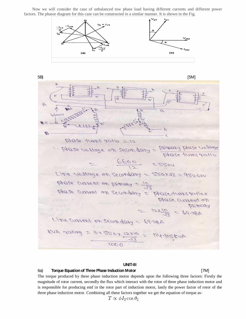
5B) [5M]
UNIT-III 6a) Torque Equation of Three Phase Induction Motor [7M] The torque produced by three phase induction motor depends upon the following three factors: Firstly the magnitude of rotor current, secondly the flux which interact with the rotor of three phase induction motor and is responsible for producing emf in the rotor part of induction motor, lastly the power factor of rotor of the three phase induction motor. Combining all these factors together we get the equation of torque as-

Where, T is the torque produced by induction motor, φ is flux responsible for producing induced emf, I2 is rotor current, cosθ2 is the power factor of rotor circuit. The flux φ produced by the stator is proportional to stator emf E1. i.e φ ∝ E1 We know that transformation ratio K is defined as the ratio of secondary voltage (rotor voltage) to that of primary voltage (stator voltage).
Rotor current I2 is defined as the ratio of rotor induced emf under running condition , sE2 to total impedance,
Z2 of rotor side,
and total impedance Z2 on rotor side is given by , Putting this value in above
equation we get, s= slip of Induction motor
We know that power factor is defined as ratio of resistance to that of impedance. The power factor of the rotor
circuit is Putting the value of flux φ, rotor current I2, power factor
cosθ2 in the equation of torque we get,
Combining similar term we get, Removing proportionality constant we get,
Where ns is synchronous speed in r. p. s, ns = Ns / 60. So, finally the
equation of torque becomes,
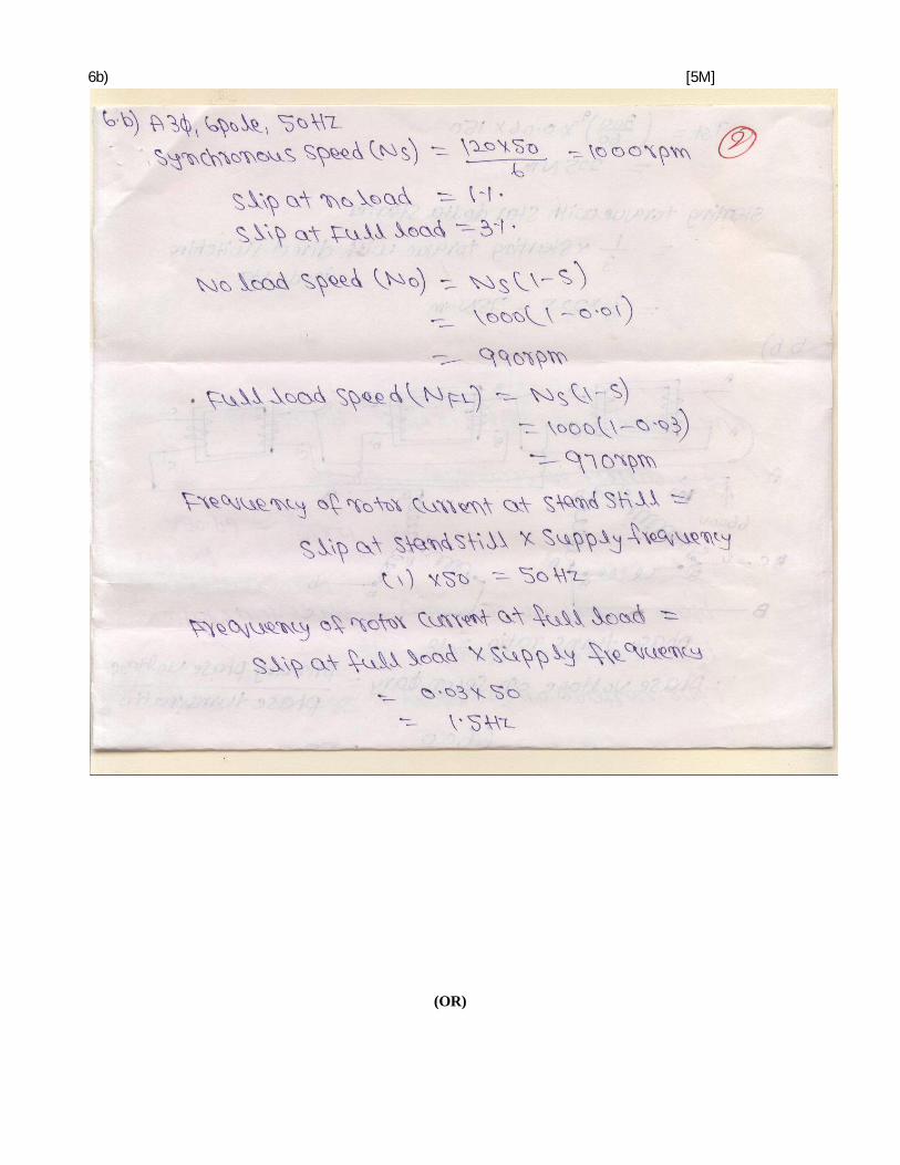
6b) [5M]
(OR)

7) [12M]


UNIT-IV 8a) out of 5 write any 2 [7M]


8b) [5M]
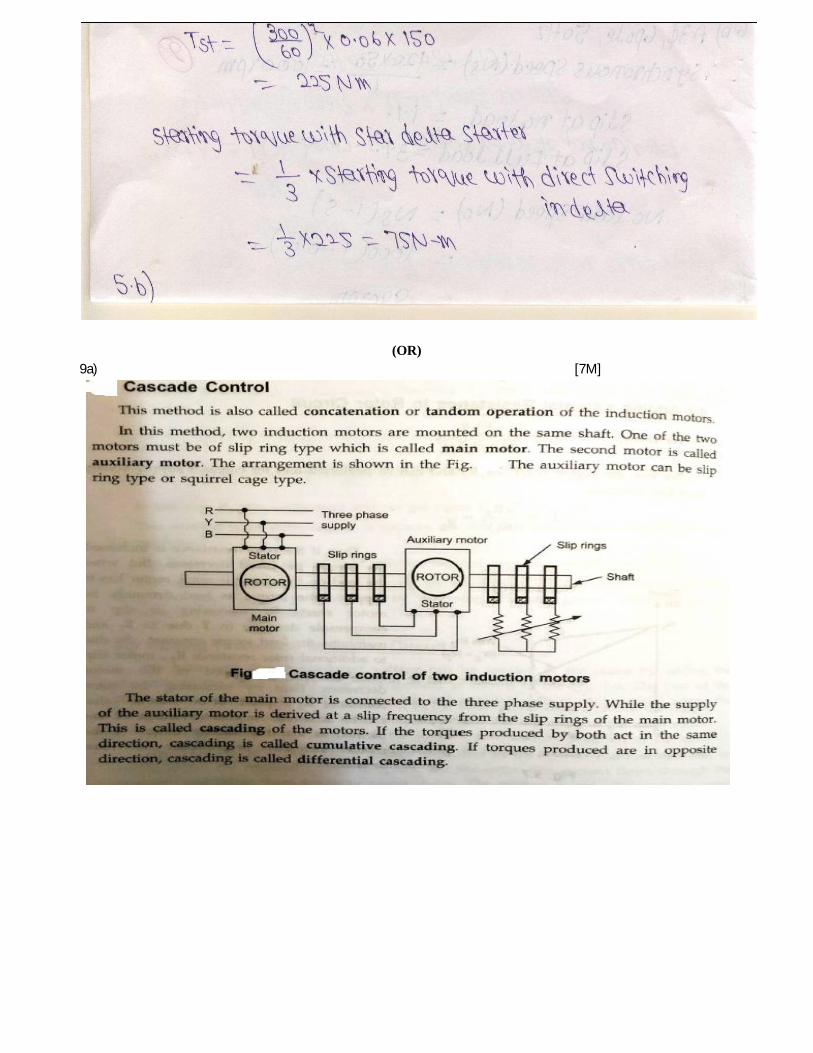
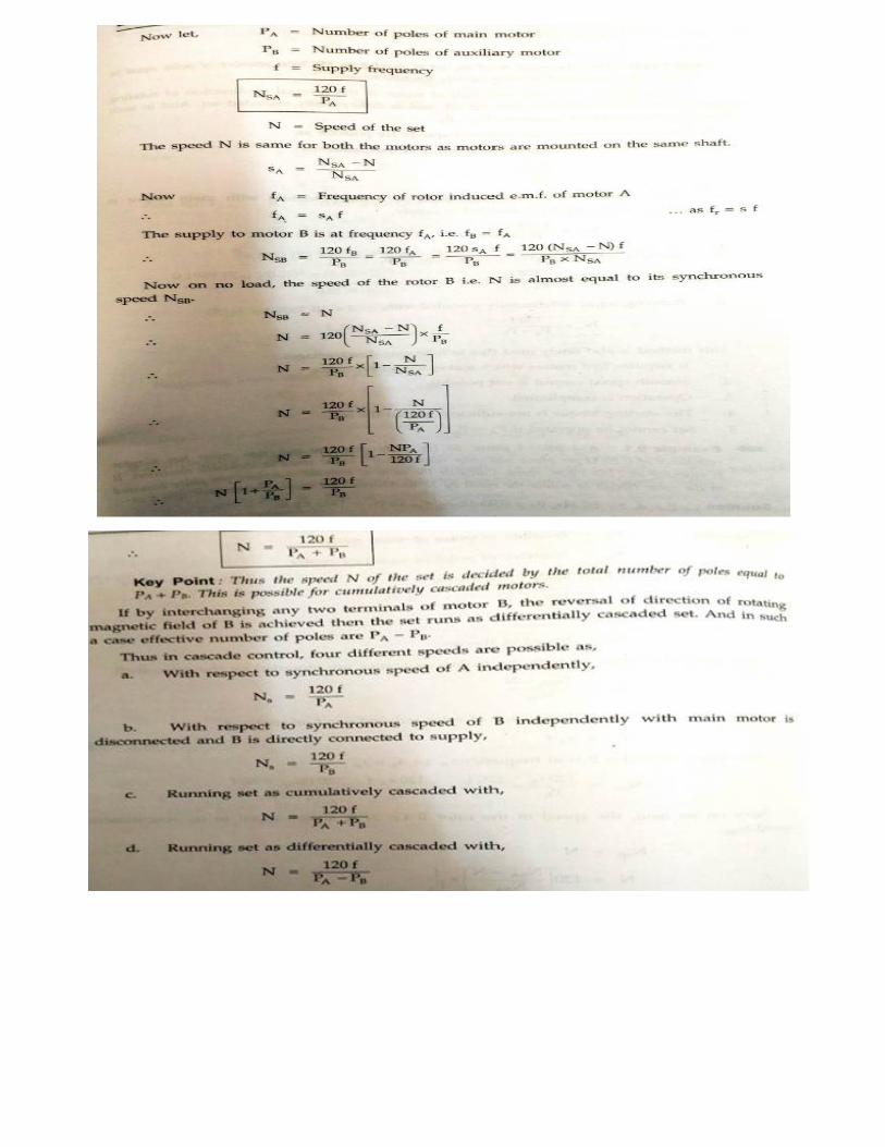
(OR) 9a) [7M]

9b) [5M]
Shaded Pole Motors
A Shaded Pole motor is an AC single phase induction motor. The auxiliary winding, which is composed of a copper ring, is called a shading coil. The current in this coil delay the phase of magnetic flux in that part of the pole in order to provide a rotating magnetic field. The direction of rotation is from the unshaded side to the shaded ring.
Basic principles of Shaded Pole Motor
This shading-coil (ring) arrangement displaces the axis of the shaded poles from the axis of the main poles When power is applied to the stator, the flux in the main part of the pole induces a voltage in the shading coil,
which acts as a transformer secondary winding. Since the current in the secondary winding of a transformer is out of phase with the current in the primary winding. The current in the shading coil is out of phase with the current in the main field winding. Thus, the flux of the shading pole is out of phase with the flux of the main pole.
Rotating field of a Shaded Pole Motor