Transformations Definition: A mapping of one n-dimensional space onto another k-dimensional space,...
20
Transformations • Definition: A mapping of one n- dimensional space onto another k- dimensional space, which could be itself. – Example: Mapping a three dimensional object (pre-image) onto a two dimensional plane (image under the transformation) – Example: Fourier transform maps an n- dimensional time signal onto an n dimensional (–f/2 to f/2) dimension frequency domain
-
date post
21-Dec-2015 -
Category
Documents
-
view
217 -
download
0
Transcript of Transformations Definition: A mapping of one n-dimensional space onto another k-dimensional space,...
Transformations
• Definition: A mapping of one n-dimensional space onto another k-dimensional space, which could be itself.– Example: Mapping a three dimensional object
(pre-image) onto a two dimensional plane (image under the transformation)
– Example: Fourier transform maps an n-dimensional time signal onto an n dimensional (–f/2 to f/2) dimension frequency domain

Why do we need transforms?
• Some problems are easier to solve in a transformed space.
• Procedure– Transform the problem– Perform an easier algorithm in the transformed
space– Transform back to get the solution
• Example: In digital signal processing, it is not so easy to determine the filter coefficients.

Z and Laplace Transforms• Laplace Transform
– Deals with continuous audio signals– Transform time domain continuous signals to s-domain– Laplace (1749-1827) invented this technique to solve differential
equations. It takes advantage of the fact that the derivative of ex is itself.
• Z-transform– Deals with discrete signals– Transform time domain digital signals to the z-domain
• Application to digital signal processing– It is an extension to Fourier Transforms – Enables us to determine the coefficients analog (Laplace) for IIR
(Z) filters.
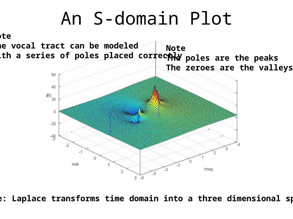
An S-domain Plot
Note: Laplace transforms time domain into a three dimensional space
NoteThe poles are the peaksThe zeroes are the valleys
NoteThe vocal tract can be modeledwith a series of poles placed correctly

The Sync Filter IllustrationTransform the rectangular time domain pulse into the frequency domain andInto the s-domain

S-domain for a notch filter
Fourier frequencies are the points where the real value is zero
Notationx = pole○ = zero

Compare S-plane to Z-plane• Filter design S: analog filters; Z: IIR filters• Equations S: differential equations, Z: difference equations• Filter Points S: rectangular along i axis, Z: polar around unit circle• Frequencies S: -∞ to ∞ (frequency line). Z: 0 – 2 π (frequency circle)• Plots S and Z: Upper and lower half are mirror images of each other
Looking down vertically from the top of the domain
Note: the Lines to left of s-plane correspond to circles within the unit circle in the z-plane
Note: Nyquist = 2π

Z- Domain Notch FilterZ1 = 1.00 ei(π/4), Z2 = 1.00 ei(-π/4)P1=0.9ei(π/4), P2=0.9ei(-π/4)
Z1=0.7071+0.7071iZ2=0.7071-0.7071iP1=0.6364+0.6364iP2=0.6364-0.6364i
Note: Compare to the s-plane example

Designing a Z-domain filter1.Pick the points for the zeroes and poles
2.Display a Z-plot using MatLab or Octave
3.When you are satisfied, convert the polar notation to rectangular form (Me-iθ to x + iy)
4.Multiply the complex polynomials
5.Collect terms
6.Use the coefficients for the filterNote: We’ll describe steps 4 through 6 later
Note: An all pole filter is a popular way to model the vocal tract

Stable and unstable IIR filters• Exponential Decay
– Points close to the origin exhibit an exponential decay in the time domain
– Points outside the unit circle have time responses that grow exponentially
– Points on the unit circle exhibit constant response in the time domain
• Filters with resonant points outside this circle are unstable and useless, leading to arithmetic overflows
• Filter design involves picking points just inside the unit circle for zeroes and poles

Fourier verses Laplace
• The basis functions– Fourier: Sinusoids– Laplace: Sinusoids and exponentials
• Transformation– Fourier: frequencies– Laplace: frequencies and exponential constants
• Fourier Transform: X(ω) = ∫-∞,∞ x(t) e-i ωt dt• Equations
– Fourier: X(ω) = ∫-∞,∞ x(t) e-i ωt dt
– Laplace: X(σ,ω)=∫-∞,∞[x(t) e-σt]e-iωt dt=∫-∞,∞x(t)e-(σ+iω)tdt=∫-∞,∞x(t)e-stdt
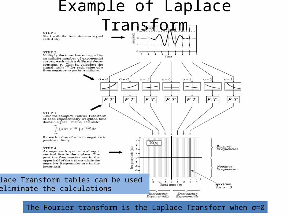
Example of Laplace Transform
The Fourier transform is the Laplace Transform when σ=0
Laplace Transform tables can be used to eliminate the calculations

The S-Domain1. Each S-Domain point has a basis function2. Like Fourier Transform, the top half is a
mirror image of the bottomReal part basis functions
Re X(σ=1.5,ω=±40) = ∫-∞,∞ x(t)cos(40t)e-1.5t dtImX(σ=1.5,ω=±40) = ∫-∞,∞ x(t)sin(40t)e-1.5t dt

Example Low Pass Filters• Butterworth poles
are equally spaced on a circle
• Chebshev poles are equally spaced on an ellipse
• Elliptic poles are on an ellipse; zeroes added to the stopband north and south of the poles

The z-transform
• Definition: X(z) = ∑n=- ∞,∞x[n]z-n where z is a complex variable
• Notes– If variable z = ej2πk/Ts
it becomes the Fourier Transform (ts=sample size)
– Using all of the other z points maps to the full Z-domain
• Linear Time Invariant (LTI) Characteristics– Linear: Z{axn + byn} = Z{axn} + Z{byn}
– Time Delay: if ym = sn-k then Yz =z-kXz Note: m = n-k and n = m+k Yz= ∑n=-∞,∞ s[n-k]z-n = ∑n=-∞,∞ s[m]z-(m+k) = z-k ∑n=-∞,∞ s[m]z-m = z-k Xz
– Note: The ym signal is the xn signal delayed by k samples. The result is that the Z transform of y is the same of the Z transform of x, but multiplied by z-k.
– Importance: Time delay and linear properties helps us find the linear coefficients

Deriving the Transfer Function
• IIR Definition: yn = b0xn + b1xn-1 +…+ bMxn-M + a1yn-1 +…+ aNyn-N
• Z transform both sides: Yz=Z{b0xn+b1xn-1+…+bMxn-M+a1yn-1+…+aNyn-N}
• Linearity: Yz = Z{b0xn}+Z{b1xn-1}+…+Z{bMxn-M}+Z{a1yn-1}+…+Z{aNyn-N}
• By time delay property (Z{xn-k} = xzz-k)Yz = b0Xz + b1Xzz-1 +…+bn-MXzz-M + a1Yzz-1+…+aNYzz-N
• Gather TermsYz - a1Yzz-1-…- aNYzz-N = b0Xz + b1Xzz-1 +…+ bn-MXz
-M
Yz(1- a1z-1-…- aNz-N ) = Xz(b0 + b1z-1 +…+ bn-Mz-M)• Divide to get transfer function
Yz/Xz= Hz= (b0 + b1z-1 +…+ bn-Mz-M)/(1- a1z-1-…- aNz-N )Yz = Xz (Yz/Xz)
• Frequency domain multiply = time domain convolution: yn = xn*hn
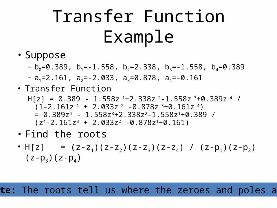
Transfer Function Example
• Suppose– b0=0.389, b1=-1.558, b2=2.338, b3=-1.558, b4=0.389– a1=2.161, a2=-2.033, a3=0.878, a4=-0.161
• Transfer FunctionH[z] = 0.389 - 1.558z-1+2.338z-2-1.558z-3+0.389z-4 /
(1-2.161z-1 + 2.033z-2 -0.878z-3+0.161z-4)= 0.389z4 - 1.558z3+2.338z2-1.558z1+0.389 /(z4-2.161z3 + 2.033z2 -0.878z1+0.161)
• Find the roots• H[z] = (z-z1)(z-z2)(z-z3)(z-z4) / (z-p1)(z-p2)(z-p3)(z-p4)
Note: The roots tell us where the zeroes and poles are

Modeling the Vocal Tract
• Numerator and Denominator of a transfer function– Each have a polynomial of some degree d having d roots– The roots of the numerator are called zeroes– The roots of the denominator are called poles
• Formant frequencies of the vocal tract– They do not affect F0– The alter the harmonics of F0– Correctly placed poles within the ZPlane unit circle mimic
the formants

Pole Placement
• Poles characterized by:– Amplitude: height of the resonance– Frequency: placement in the spectrum– Bandwidth: Sharpness of the pole
• Place pole at reiφ
– Amplitude and bandwidth shrink as r approaches the origin3-db down (half power) estimate = -2 ln(r) or 2(1-r)/r½
– φ controls the resonant frequencyWhen φ≠0, filter coefficients will be complex numbersFilter pairs will be real if they are conjugate pairs (reiφ,re-iφ)If r < 0.5, the relationship between φ and frequency breaks
down because of the “skirts” of the poles

Examples
r φ Poles a1 a2
0.8 0.75 0.58±0.54j 1.17 -1.64
0.8 1.0 0.43±0.67j 0.86 -0.64
0.8 1.25 0.25±0.76j 0.50 -0.64
0.8 1.5 0.056±0.78j 0.11 -0.64
x xx
xxx
x
x
Freq Bandwth r φ Poles
F1 300 250 0.95 0.12 0.963±0.116j
F2 2200 250 0.95 0.86 0.619±0.719j
F3 3000 250 0.95 1.17 0.370±0.874j
xx
xx
xx
Note: Normalized Angular Frequencies range from 0 to 2π