Transducer-Class Strain Gages - vishaypg.com SK-XX-S075P-350 350 ± 0.1% 350 ± 0.3% 350 ± 0.15%...
5
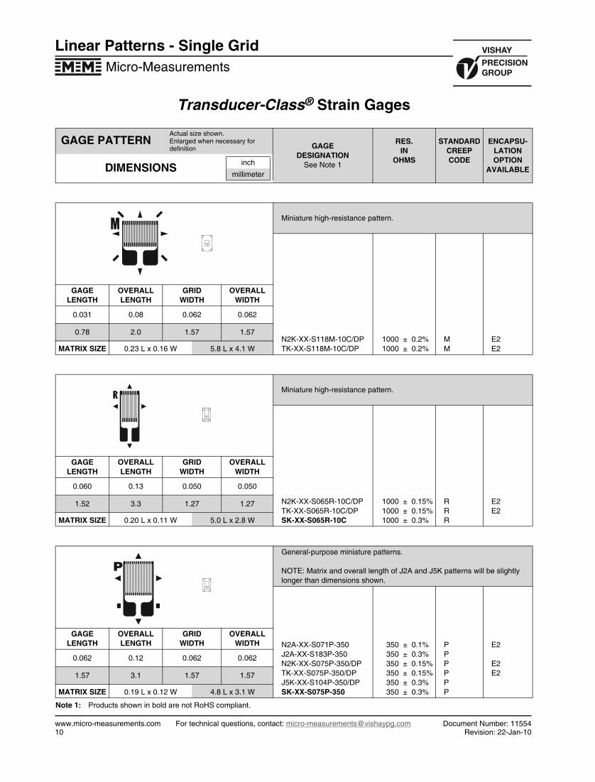
Transducer-Class ® Strain Gages Linear Patterns - Single Grid Micro-Measurements www.micro-measurements.com For technical questions, contact: [email protected] Document Number: 11554 10 Revision: 22-Jan-10 Note 1: Products shown in bold are not RoHS compliant. GAGE PATTERN Actual size shown. Enlarged when necessary for definition GAGE DESIGNATION See Note 1 RES. IN OHMS STANDARD CREEP CODE ENCAPSU- LATION OPTION AVAILABLE DIMENSIONS inch millimeter Miniature high-resistance pattern. N2K-XX-S118M-10C/DP TK-XX-S118M-10C/DP 1000 ± 0.2% 1000 ± 0.2% M M E2 E2 GAGE LENGTH OVERALL LENGTH GRID WIDTH OVERALL WIDTH 0.031 0.08 0.062 0.062 0.78 2.0 1.57 1.57 MATRIX SIZE 0.23 L x 0.16 W 5.8 L x 4.1 W Miniature high-resistance pattern. N2K-XX-S065R-10C/DP TK-XX-S065R-10C/DP SK-XX-S065R-10C 1000 ± 0.15% 1000 ± 0.15% 1000 ± 0.3% R R R E2 E2 GAGE LENGTH OVERALL LENGTH GRID WIDTH OVERALL WIDTH 0.060 0.13 0.050 0.050 1.52 3.3 1.27 1.27 MATRIX SIZE 0.20 L x 0.11 W 5.0 L x 2.8 W General-purpose miniature patterns. NOTE: Matrix and overall length of J2A and J5K patterns will be slightly longer than dimensions shown. N2A-XX-S071P-350 J2A-XX-S183P-350 N2K-XX-S075P-350/DP TK-XX-S075P-350/DP J5K-XX-S104P-350/DP SK-XX-S075P-350 350 ± 0.1% 350 ± 0.3% 350 ± 0.15% 350 ± 0.15% 350 ± 0.3% 350 ± 0.3% P P P P P P E2 E2 E2 GAGE LENGTH OVERALL LENGTH GRID WIDTH OVERALL WIDTH 0.062 0.12 0.062 0.062 1.57 3.1 1.57 1.57 MATRIX SIZE 0.19 L x 0.12 W 4.8 L x 3.1 W P
Transcript of Transducer-Class Strain Gages - vishaypg.com SK-XX-S075P-350 350 ± 0.1% 350 ± 0.3% 350 ± 0.15%...
®
Linear Patterns - Single GridMicro-Measurements
Transducer-Class Strain Gages
Note 1: Products shown in bold are not RoHS compliant.
GAGE PATTERNActual size shown.Enlarged when necessary for definition GAGE
DESIGNATIONSee Note 1
RES.IN
OHMS
STANDARDCREEPCODE
ENCAPSU- LATIONOPTION
AVAILABLEDIMENSIONS inch
millimeter
Miniature high-resistance pattern.
N2K-XX-S118M-10C/DPTK-XX-S118M-10C/DP
1000 ± 0.2%1000 ± 0.2%
MM
E2E2
GAGELENGTH
OVERALLLENGTH
GRIDWIDTH
OVERALLWIDTH
0.031 0.08 0.062 0.062
0.78 2.0 1.57 1.57
MATRIX SIZE 0.23 L x 0.16 W 5.8 L x 4.1 W
Miniature high-resistance pattern.
N2K-XX-S065R-10C/DPTK-XX-S065R-10C/DPSK-XX-S065R-10C
1000 ± 0.15%1000 ± 0.15%1000 ± 0.3%
RRR
E2E2
GAGELENGTH
OVERALLLENGTH
GRIDWIDTH
OVERALLWIDTH
0.060 0.13 0.050 0.050
1.52 3.3 1.27 1.27
MATRIX SIZE 0.20 L x 0.11 W 5.0 L x 2.8 W
General-purpose miniature patterns.
NOTE: Matrix and overall length of J2A and J5K patterns will be slightly longer than dimensions shown.
N2A-XX-S071P-350J2A-XX-S183P-350N2K-XX-S075P-350/DPTK-XX-S075P-350/DPJ5K-XX-S104P-350/DPSK-XX-S075P-350
350 ± 0.1%350 ± 0.3%350 ± 0.15%350 ± 0.15%350 ± 0.3%350 ± 0.3%
PPPPPP
E2
E2E2
GAGELENGTH
OVERALLLENGTH
GRIDWIDTH
OVERALLWIDTH
0.062 0.12 0.062 0.062
1.57 3.1 1.57 1.57
MATRIX SIZE 0.19 L x 0.12 W 4.8 L x 3.1 W
P
www.micro-measurements.com For technical questions, contact: [email protected] Document Number: 1155410 Revision: 22-Jan-10

Transducer-Class® Strain Gages
Linear Patterns - Single GridMicro-Measurements
Note 1: Products shown in bold are not RoHS compliant.
GAGE PATTERNActual size shown.Enlarged when necessary for definition GAGE
DESIGNATION See Note 1
RES.IN
OHMS
STANDARDCREEPCODE
ENCAPSU- LATIONOPTION
AVAILABLEDIMENSIONS inch
millimeter
The most popular small gage pattern.
N2A-XX-S148P-120N2A-XX-S106N-175N2A-XX-T001N-350N2A-XX-T010P-10CJ2A-XX-S148P-120J2A-XX-S106N-175J2A-XX-S047K-350J2A-XX-S110K-10CN2K-XX-S123R-175/DPN2K-XX-T009N-350/DPN2K-XX-S072R-10C/DPTK-XX-S123R-175/DPTK-XX-T009Q-350/DPTK-XX-S072R-10C/DPJ5K-XX-S103Q-350/DPSK-XX-S074R-350SK-XX-S072R-10C
120 ± 0.15%175 ± 0.15%350 ± 0.15%1000 ± 0.15%120 ± 0.3%175 ± 0.3%350 ± 0.3%1000 ± 0.3%175 ± 0.15%350 ± 0.15%1000 ± 0.15%175 ± 0.15%350 ± 0.15%1000 ± 0.15%350 ± 0.3%350 ± 0.3%1000 ± 0.3%
PNNPPNKKRNRRQRQRR
E2E2E2E2
E2E2E2E2E2E2
GAGELENGTH
OVERALLLENGTH
GRIDWIDTH
OVERALLWIDTH
0.060 0.15 0.100 0.100
1.52 3.8 2.54 2.54
MATRIX SIZE 0.22 L x 0.16 W 5.6 L x 4.1 W
Higher-power-dissipation versions of the T001/T009 patterns.
N2A-XX-T002Q-350N2K-XX-T003Q-350/DPTK-XX-T003Q-350/DP
350 ± 0.15%350 ± 0.15%350 ± 0.15%
QQQ
E2E2E2
GAGELENGTH
OVERALLLENGTH
GRIDWIDTH
OVERALLWIDTH
0.060 0.17 0.180 0.180
1.52 4.3 4.57 4.57
MATRIX SIZE 0.24 L x 0.24 W 6.1 L x 6.1 W
One of the most popular gage sizes.
†Overall length on S078/S080 is 0.25 in (6.4mm). Matrix length will also increase slightly.
N2A-XX-S107N-120N2A-XX-T004R-350N2A-XX-T096R-500N2A-XX-S108N-10CJ2A-XX-S108N-10CN2K-XX-T005R-350/DPN2K-XX-S163R-500/DPN2K-XX-S078W-10C/DPTK-XX-T005R-350/DPTK-XX-S078W-10C/DPSK-XX-S080W-350SK-XX-S078W-10C
120 ± 0.15%350 ± 0.15%500 ± 0.15%1000 ± 0.15%1000 ± 0.3%350 ± 0.15%500 ± 0.15%1000 ± 0.15%350 ± 0.15%1000 ± 0.15%350 ± 0.3%1000 ± 0.3%
NRRNNRRWRWWW
E2E2E2E2
E2E2E2E2E2
GAGELENGTH
OVERALLLENGTH
GRIDWIDTH
OVERALLWIDTH
0.125 0.23† 0.125 0.125
3.18 5.8† 3.18 3.18
MATRIX SIZE 0.29 L x 0.19 W 7.4 L x 4.8 W
R
Document Number: 11554 For technical questions, contact: [email protected] www.micro-measurements.comRevision: 22-Jan-10 11

Transducer-Class® Strain Gages
Linear Patterns - Single GridMicro-Measurements
Note 1: Products shown in bold are not RoHS compliant.
GAGE PATTERNActual size shown.Enlarged when necessary for definition
GAGEDESIGNATION
See Note 1
RES.IN
OHMS
STANDARDCREEPCODE
ENCAPSU- LATIONOPTION
AVAILABLEDIMENSIONS inch
millimeter
One of the most popular gage sizes.
J2A-XX-S033P-350J2A-XX-S182K-10CN2K-XX-S081P-20C/DPTK-XX-S081P-20C/DPJ5K-XX-S100P-350/DP
350 ± 0.3%1000 ± 0.3%2000 ± 0.3%2000 ± 0.3%350 ± 0.3%
PKPPP
E2E2
GAGELENGTH
OVERALLLENGTH
GRIDWIDTH
OVERALLWIDTH
0.125 0.21 0.100 0.100
3.18 5.6 2.54 2.54
MATRIX SIZE 0.28 L x 0.16 W 7.1 L x 4.1 W
Tabs at both ends of grid for simplified wiring on some transducer designs.
N2A-XX-S044Q-350 350 ± 0.15% Q E2
GAGELENGTH
OVERALLLENGTH
GRIDWIDTH
OVERALLWIDTH
0.125 0.255 0.125 0.125
3.18 6.48 3.18 3.18
MATRIX SIZE 0.32 L x 0.19 W 8.1 L x 4.7 W
Narrow, encapsulated version of S044.
J2A-XX-S113M-350 350 ± 0.3% M
GAGELENGTH
OVERALLLENGTH
GRIDWIDTH
OVERALLWIDTH
0.110 0.285 0.080 0.080
2.82 7.31 2.03 2.03
MATRIX SIZE 0.34 L x 0.14 W 8.7 L x 3.6 W
M
www.micro-measurements.com For technical questions, contact: [email protected] Document Number: 1155412 Revision: 22-Jan-10

Transducer-Class® Strain Gages
Linear Patterns - Single GridMicro-Measurements
Note 1: Products shown in bold are not RoHS compliant.
GAGE PATTERNActual size shown.Enlarged when necessary for definition
GAGEDESIGNATION
See Note 1
RES.IN
OHMS
STANDARDCREEPCODE
ENCAPSU- LATIONOPTION
AVAILABLEDIMENSIONS inch
millimeter
Narrow-grid version of T004/T005.
N2A-XX-T019M-350J2A-XX-S038M-350N2K-XX-T020T-350/DPTK-XX-T020T-350/DP
350 ± 0.15%350 ± 0.3%350 ± 0.15%350 ± 0.15%
MMTT
E2
E2E2
GAGELENGTH
OVERALLLENGTH
GRIDWIDTH
OVERALLWIDTH
0.125 0.20 0.060 0.070
3.18 5.1 1.52 1.78
MATRIX SIZE 0.27 L x 0.12 W 6.9 L x 3.0 W
Longer grid for strain averaging or where higher power dissipation is required.
N2A-XX-T007R-350J2A-XX-S109M-350N2K-XX-T008R-350/DPTK-XX-T008R-350/DP
350 ± 0.15%350 ± 0.3%350 ± 0.15%350 ± 0.15%
RMRR
E2
E2E2
GAGELENGTH
OVERALLLENGTH
GRIDWIDTH
OVERALLWIDTH
0.250 0.37 0.125 0.125
6.35 9.4 3.18 3.18
MATRIX SIZE 0.44 L x 0.19 W 11.2 L x 4.8 W
Large grid and high resistance permit higher-than-normal excitation voltage.
N2A-XX-S051R-10C 1000 ± 0.15% R E2
GAGELENGTH
OVERALLLENGTH
GRIDWIDTH
OVERALLWIDTH
0.250 0.36 0.175 0.175
6.35 9.1 4.45 4.45
MATRIX SIZE 0.42 L x 0.24 W 10.7 L x 6.1 W
M
M
Document Number: 11554 For technical questions, contact: [email protected] www.micro-measurements.comRevision: 22-Jan-10 13

Vishay Precision Group, Inc.
www.vpgsensors.com1
Legal Disclaimer Notice
Document No.: 63999Revision: 15-Jul-2014
DisclaimerALL PRODUCTS, PRODUCT SPECIFICATIONS AND DATA ARE SUBJECT TO CHANGE WITHOUT NOTICE.
Vishay Precision Group, Inc., its affiliates, agents, and employees, and all persons acting on its or their behalf (collectively, “VPG”), disclaim any and all liability for any errors, inaccuracies or incompleteness contained herein or in any other disclosure relating to any product.
The product specifications do not expand or otherwise modify VPG’s terms and conditions of purchase, including but not limited to, the warranty expressed therein.
VPG makes no warranty, representation or guarantee other than as set forth in the terms and conditions of purchase. To the maximum extent permitted by applicable law, VPG disclaims (i) any and all liability arising out of the application or use of any product, (ii) any and all liability, including without limitation special, consequential or incidental damages, and (iii) any and all implied warranties, including warranties of fitness for particular purpose, non-infringement and merchantability.
Information provided in datasheets and/or specifications may vary from actual results in different applications and performance may vary over time. Statements regarding the suitability of products for certain types of applications are based on VPG’s knowledge of typical requirements that are often placed on VPG products. It is the customer’s responsibility to validate that a particular product with the properties described in the product specification is suitable for use in a particular application. You should ensure you have the current version of the relevant information by contacting VPG prior to performing installation or use of the product, such as on our website at vpgsensors.com.
No license, express, implied, or otherwise, to any intellectual property rights is granted by this document, or by any conduct of VPG.
The products shown herein are not designed for use in life-saving or life-sustaining applications unless otherwise expressly indicated. Customers using or selling VPG products not expressly indicated for use in such applications do so entirely at their own risk and agree to fully indemnify VPG for any damages arising or resulting from such use or sale. Please contact authorized VPG personnel to obtain written terms and conditions regarding products designed for such applications.
Product names and markings noted herein may be trademarks of their respective owners.
Copyright Vishay Precision Group, Inc., 2014. All rights reserved.
Disclaimer
Legal Disclaimer Notice