TRANSACTIONS ON ENERGY CONVERSION, VOL. X, NO. Y, …
9
TRANSACTIONS ON ENERGY CONVERSION, VOL. X, NO. Y, MARCH 201X 1 Virtual Prototyping and Distributed Control for Solar Array with Distributed Multilevel Inverter Luan Viet Nguyen, Student Member, IEEE and Taylor T Johnson, Member, IEEE Abstract—In this paper, we present the virtual prototyping of a solar array with a grid-tie implemented as a distributed inverter and controlled using distributed algorithms. Due to the distributed control and inherent redundancy in the array composed of many panels and inverter modules, the virtual prototype exhibits fault-tolerance capabilities. The distributed identifier algorithm allows the system to keep track of the number of operating panels to appropriately regulate the DC voltage output of the panels using buck-boost converters, and determine appropriate switching times for H-bridges in the grid-tie. We evaluate the distributed inverter, its control strategy, and fault- tolerance through simulation in Simulink/Stateflow. Our virtual prototyping framework allows for generating arrays and grid- ties consisting of many panels, and we evaluate arrays of five to dozens of panels. Our analysis suggests the achievable total harmonic distortion (THD) of the system may allow for operating the array in spite of failures of the power electronics, control software, and other subcomponents. Index Terms—distributed control, multilevel inverter, dis- tributed inverter, solar array. I. I NTRODUCTION Multilevel inverters have become popular in recent years for a plethora of reasons, such as their ease of implemen- tation, efficiency, fault-tolerance capabilities, etc. [1]–[7]. In this paper, we describe the model-based design and virtual prototyping analysis of a grid-tied solar array implemented with fault-tolerant distributed control. The solar array consists of N solar panels composed of photovoltaic (PV) modules and corresponding electronics. Each panel’s electronics implement maximum power-point tracking (MPPT) and regulate the panel output voltage using a buck-booster converter. A (2N+1)-level multilevel inverter is implemented using H-bridges to create a grid-tie. The control logic for each panel, corresponding buck-booster converter, and H-bridge module is implemented using a separate microcontroller. An inverter module is the complete plant and computer controller consisting of a panel, its microcontroller, buck-boost converter, etc. See Figure 1 for an overview of the array architecture. The modules communicate with one another to ensure they switch at appropriate times to create the AC waveform for the grid. Next, a distributed identifier service is used by the N microcontrollers to determine (a) the number of non- faulty modules, and (b) the switching time for each non- faulty module to minimize total harmonic distortion (THD) for the AC grid-tie [8]. This setup makes the system modular, L.V. Nguyen and T.T. Johnson are with the Department of Computer Science and Engineering, University of Texas at Arlington, Arlington, TX 76019 USA, e-mail: ([email protected], [email protected]. Manuscript received March 17, 2014; revised xxx. Inverter Module Solar Panel Buck- Boost Converter H-Bridge Microcontroller Sunlight Grid … (N-2 times) Inverter Module Solar Panel Buck- Boost Converter H-Bridge Microcontroller Sunlight Network Connection Fig. 1. Overview of the grid-tied solar array, consisting of N inverter modules, each of which is composed of a solar panel, a microcontroller, a buck-boost converter, and an H-bridge for selecting polarity. where it is not necessary to know the number of functioning modules N O ≤ N, a priori, as the distributed algorithm determines this. In addition, the distributed identifier service lends the system to be fault-tolerant, whereby if any of the N panels and corresponding control modules fails, the remaining panels and modules continue operating to ensure the grid-tie remains operational with reasonable THD and response time. We utilize an abstract failure model, where crash faults of any microcontroller are detected and tolerated, as are actuator stuck-at errors, which corresponds to failed switches in the H- bridges. We characterize the THD of the system as a function of N F , the number of faulty modules, since as the number of faulty modules increases, the best response of the array will decrease, as the sinusoidal approximation has fewer discrete levels. In the optimal case, the best achievable THD of an array with N total modules and N F faulty modules is that of an array with N O = N - N F functioning modules. Related Work: There is extensive literature [9]–[19] re- garding fault-tolerance capabilities of single and multi-phase multilevel inverters, as due to their topology, they have inher- ent redundancy that may be useful for providing fault-tolerance due to switch and other failures. For a recent overview of general reliability and fault-tolerance in power electronics, see [16], for a particular focus on multilevel inverters, see [15], and for a focus on the reliability of DC-to-DC converters in PV energy conversion systems, see [20]. In [9] the reliability of multilevel inverters was studied to present an argument against reliability necessarily decreasing due to increased component counts, each with their own failure rates. A single-phase arXiv:1404.2259v1 [cs.DC] 8 Apr 2014
Transcript of TRANSACTIONS ON ENERGY CONVERSION, VOL. X, NO. Y, …

TRANSACTIONS ON ENERGY CONVERSION, VOL. X, NO. Y, MARCH 201X 1
Virtual Prototyping and Distributed Control forSolar Array with Distributed Multilevel Inverter
Luan Viet Nguyen, Student Member, IEEE and Taylor T Johnson, Member, IEEE
Abstract—In this paper, we present the virtual prototypingof a solar array with a grid-tie implemented as a distributedinverter and controlled using distributed algorithms. Due tothe distributed control and inherent redundancy in the arraycomposed of many panels and inverter modules, the virtualprototype exhibits fault-tolerance capabilities. The distributedidentifier algorithm allows the system to keep track of the numberof operating panels to appropriately regulate the DC voltageoutput of the panels using buck-boost converters, and determineappropriate switching times for H-bridges in the grid-tie. Weevaluate the distributed inverter, its control strategy, and fault-tolerance through simulation in Simulink/Stateflow. Our virtualprototyping framework allows for generating arrays and grid-ties consisting of many panels, and we evaluate arrays of fiveto dozens of panels. Our analysis suggests the achievable totalharmonic distortion (THD) of the system may allow for operatingthe array in spite of failures of the power electronics, controlsoftware, and other subcomponents.
Index Terms—distributed control, multilevel inverter, dis-tributed inverter, solar array.
I. INTRODUCTION
Multilevel inverters have become popular in recent yearsfor a plethora of reasons, such as their ease of implemen-tation, efficiency, fault-tolerance capabilities, etc. [1]–[7]. Inthis paper, we describe the model-based design and virtualprototyping analysis of a grid-tied solar array implementedwith fault-tolerant distributed control. The solar array consistsof N solar panels composed of photovoltaic (PV) modules andcorresponding electronics. Each panel’s electronics implementmaximum power-point tracking (MPPT) and regulate the paneloutput voltage using a buck-booster converter. A (2N+1)-levelmultilevel inverter is implemented using H-bridges to createa grid-tie. The control logic for each panel, correspondingbuck-booster converter, and H-bridge module is implementedusing a separate microcontroller. An inverter module is thecomplete plant and computer controller consisting of a panel,its microcontroller, buck-boost converter, etc. See Figure 1 foran overview of the array architecture.
The modules communicate with one another to ensure theyswitch at appropriate times to create the AC waveform forthe grid. Next, a distributed identifier service is used bythe N microcontrollers to determine (a) the number of non-faulty modules, and (b) the switching time for each non-faulty module to minimize total harmonic distortion (THD)for the AC grid-tie [8]. This setup makes the system modular,
L.V. Nguyen and T.T. Johnson are with the Department of ComputerScience and Engineering, University of Texas at Arlington, Arlington, TX76019 USA, e-mail: ([email protected], [email protected].
Manuscript received March 17, 2014; revised xxx.
Inverter Module
Solar Panel
Buck-Boost
ConverterH-Bridge
Microcontroller
Sunlight
Grid… (N-2 times)
Inverter Module
Solar Panel
Buck-Boost
ConverterH-Bridge
Microcontroller
Sunlight
Network Connection
Fig. 1. Overview of the grid-tied solar array, consisting of N inverter modules,each of which is composed of a solar panel, a microcontroller, a buck-boostconverter, and an H-bridge for selecting polarity.
where it is not necessary to know the number of functioningmodules NO ≤ N, a priori, as the distributed algorithmdetermines this. In addition, the distributed identifier servicelends the system to be fault-tolerant, whereby if any of the Npanels and corresponding control modules fails, the remainingpanels and modules continue operating to ensure the grid-tieremains operational with reasonable THD and response time.We utilize an abstract failure model, where crash faults ofany microcontroller are detected and tolerated, as are actuatorstuck-at errors, which corresponds to failed switches in the H-bridges. We characterize the THD of the system as a functionof NF, the number of faulty modules, since as the number offaulty modules increases, the best response of the array willdecrease, as the sinusoidal approximation has fewer discretelevels. In the optimal case, the best achievable THD of anarray with N total modules and NF faulty modules is that ofan array with NO = N− NF functioning modules.
Related Work: There is extensive literature [9]–[19] re-garding fault-tolerance capabilities of single and multi-phasemultilevel inverters, as due to their topology, they have inher-ent redundancy that may be useful for providing fault-tolerancedue to switch and other failures. For a recent overview ofgeneral reliability and fault-tolerance in power electronics,see [16], for a particular focus on multilevel inverters, see [15],and for a focus on the reliability of DC-to-DC converters in PVenergy conversion systems, see [20]. In [9] the reliability ofmultilevel inverters was studied to present an argument againstreliability necessarily decreasing due to increased componentcounts, each with their own failure rates. A single-phase
arX
iv:1
404.
2259
v1 [
cs.D
C]
8 A
pr 2
014

TRANSACTIONS ON ENERGY CONVERSION, VOL. X, NO. Y, MARCH 201X 2
fault-tolerant multilevel inverter is developed and experimen-tally validated with 5-level prototype in [10] and focuseson utilizing redundant circuitry and appropriate control formaintaining the output voltage. For example, Fault-tolerancein multilevel inverters can be achieved by adding some powerdevice to the basic topologies such as fourth-leg [21] orreconfiguring the flying capacitor multilevel inverter into a fullbinary combination scheme, and balance capacitor voltage byusing three-phase joint switching states [22]. A comparison ofseveral inverter topologies along with their cost and reliabilitytradeoffs is presented in [11]. In [12], a strategy is developedfor reconfiguring carrier-based modulation signals to providefault-tolerance in multilevel inverters due to switches eitherfailing open circuit or short circuit, and is experimentallyevaluated on a three-phase five-level prototype. The authorsof [13] develop a fault diagnosis system for multilevel invertersusing neural networks.
Overall, the vast majority of fault-tolerance capabilities inmultilevel inverters focus on handling hardware faults usingredundant hardware and topology (i.e., physical) solutions. Incontrast, in this paper, we consider primarily software-basedfault-tolerance methods and have the capability to handleboth hardware (e.g., switch failures) and software faults (e.g.,microcontroller crashes) using software (i.e., cyber) solutions.The topology of the inverter we consider in this paper isvery similar to that of [7], [23], but we utilize a buck-boost converter for DC voltage regulation, and we focus ondistributed control instead of communication-less control. Wedo not focus on any particular maximum power point tracking(MPPT) scheme in this paper, but refer readers to numerousmethods and their tradeoffs in [24].
Our array simulator is developed in Simulink/Stateflow,and similar simulation models have been developed pre-viously [25]–[28]. A MATLAB simulation model for PVmodules is presented in [25] and considers factors such astemperature, shading, etc. In [26], the authors develop aMATLAB/Simulink model of a grid-connected single-phasearray with MPPT, but do not consider multilevel invertersas we do. In [27], the authors develop a MATLAB/Simulinkmodel of PV modules accounting for numerous non-idealities,such as nonuniform irradiance. A detailed MATLAB/Simulinkfor studying partial shading of arrays is studied in [28].
Contributions: The main contributions of this paper are:(a) the development and implementation of the fault-tolerantdistributed control strategy for solar-to-AC conversion, (b) theholistic design and analysis of a cyber-physical system (CPS)in a virtual prototyping environment (MATLAB/Simulink/S-tateflow), and (c) the application of hybrid systems modelingtechniques for virtual prototyping. We highlight that in contrastto most existing work on fault-tolerance of multilevel inverters,the failure model considered in this paper is an abstraction ofboth cyber and physical failures, and works by coordinationthrough distributed control.
Paper Organization: The remainder of this paper isorganized as follows. Section II presents the distributed solararray architecture and its control, including the communicationand computation capabilities of its subcomponents, as well asa failure model of the subcomponents. Section III presents the
simulation-based analysis of the virtual prototype, includingcomparisons of THD with and without failures, differentfailure modes, and arrays consisting of N = 5 to N = 35panels. Section IV concludes the paper and presents directionsfor future work.
II. DISTRIBUTED ARRAY ARCHITECTURE AND MODELING
Preliminaries: For a set S, let |S| be the cardinalityof S, which is the number of elements in S. For a set S,let S⊥ be S ∪ ⊥ where ⊥ /∈ S. We model several ofthe cyber-physical components of the array using the hybridautomaton formalisms, and refer interested readers to [29]–[32] for detailed definitions of such modeling formalisms, andto [33]–[36] for descriptions specified to power electronicsand systems. We begin by briefly reviewing hybrid automata.A hybrid automaton is a (possibly nondeterministic) state ma-chine with state that can evolve both instantaneously (throughdiscrete transitions) and over intervals of time (according totrajectories). Variables are associated with types and are usedas names for state components, such as currents, voltages, andtimes. For a set of variables V , a valuation v is a functionthat maps each variable v ∈ V to a point in its type, denotedtype(v). The set of all possible valuations is val(V ). For avaluation x, we use x.x to denote the value of the variablex ∈ V . Since the distributed system is composed of N panels,each of which has its own power electronics, software, etc.,we model the ith panel as an automaton Ai.
Mathematically, a hybrid automaton Ai is a tuple〈Vari , Loci, Qi,Θi,Edg i,Grd i,Rst i,Flow i, Inv i〉, where:(a) Vari : is a set of variables, where Xi ⊆ Vari are thecontinuous, real-typed variables. (b) Loci: is a set of discretelocations. (c) Qi
∆= val(Vari) is the set of states, and is
the set of all valuations of each variable v ∈ Vari . Astate is denoted by bold x and assigns values to everyvariable in the set of variables Vari . For a state x ∈ Qi,the valuation of x.loc is called the location, and along withthe valuations of any discrete variables, it describes thediscrete state. The valuation of the continuous variables inXi , that is x.x : x ∈ Xi, is called the continuous stateand is referred to as x.Xi . (d) Θi ⊆ Qi is a set of initialstates. (e) Edg i is the set of edges. (f) Grd i : Edg i → Qi
is a function that associates a guard (a valuation of Vthat must be satisfied such that a transition may be taken)with each edge. (g) Rst i : Edg i → (Qi → 2Qi) is afunction, called the reset map, associated with each edge.A reset map associates a set of states with each edge.(h) Flow i : Loci → (Qi → 2Qi) associates a flow map witheach location. (i) Inv i : Loci → 2Qi associates an invariantwith each location.
The semantics of Ai are defined in terms of sets of tran-sitions and trajectories. The set of transitions Di ⊆ Qi × Qi
is defined as follows. We have (v,v′) ∈ Di if and only if,for e = (v.loc,v′.loc), (a) e ∈ Edg i, (b) v ∈ Grd i(e), and(c) v′ ∈ Rst i(e)(v.X). A trajectory for Ai is a functionτ : [0, t]→ Qi that maps an interval of time to states such that:(a) For all t′ ∈ [0, t], τ(t′).loc = τ(0).loc, that is, the discretestate remains constant, (b) (τ ↓ X), that is, the restriction of

TRANSACTIONS ON ENERGY CONVERSION, VOL. X, NO. Y, MARCH 201X 3
τ to Xi is a solution of the differential equation specified bythe flow function Xi = Flow i(τ(0).loc)(τ(0)), and (c) For allt′ ∈ [0, t], τ(t′) ∈ Inv i(τ(0).loc). The set of all the trajectoriesof Ai is written Ti. The domain for a trajectory τ ∈ Ti isdenoted by τ.dom. We define τ. ltime as the right endpointof τ.dom, τ. lstate ∆
= τ(τ. ltime), and τ. fstate∆= τ(0). An
execution of Ai is a sequence α = τ0τ1 . . ., such that: (a) eachτk ∈ Ti, (b) for each k, (τk(t), τk+1(0)) ∈ Di, where t is theright endpoint of the domain of τk, and (c) τ0 ∈ Θi. A statev ∈ Qi is said to be reachable if there exists a finite executionα that ends with v.
A. Architecture and ModelingThe distributed solar array consists of N solar panels
and corresponding electronics for implementing the grid-tie(see Figure 1). For each solar panel, there is also an invertermodule consisting of a computer, communications system, andpower electronics. Each inverter module’s power electronicsconsist of a DC-to-DC buck-boost converter for regulatingthe panel’s output voltage, and an H-bridge for connectingand disconnecting the panel’s output voltage at appropriatetimes to generate the AC waveform (see Figure 2). We refer toeach panel and its corresponding inverter module as an agentwith a unique identifier i ∈ ID , where ID
∆= 1, . . . ,N. We
model the ith solar panel’s buck-boost converter as a hybridautomaton (see Figure 4) denoted Adc
i , and its H-bridge as ahybrid automaton (see Figure 6) denoted Aac
i . Each panel andinverter module is specified as a hybrid automaton consistingof the composition of the individual components:
Ai∆= Adc
i ‖ Aaci . (1)
For a given N, the complete system A composed of the N solarpanels, N buck-boost converters, N H-bridges, and computercontrol software and hardware is:
A ∆= A1 ‖ . . . ‖ AN, (2)
where ‖ is a parallel (concurrent) composition of automata(see, e.g., [32, Chapter 2]).
Each agent i ∈ ID is associated with the following electrical(physical) real variables: (a) V sp
i : the voltage output of agenti’s solar panel and input to agent i’s DC-to-DC converter,(b) Ispi : the output current of agent i’s solar panel and input toagent i’s DC-to-DC converter, (c) V ref
i : the reference voltagefor agent i’s DC-to-DC converter to track, (d) V dc
i : the voltageoutput of agent i’s DC-to-DC converter and input to agenti’s H-bridge, (e) Idci : the current output of agent i’s DC-to-DC converter and input to agent i’s H-bridge, (f) V ac
i : thevoltage output of agent i’s H-bridge and input to the grid, and(g) Iaci : the current output of agent i’s H-bridge and inputto the grid. Additionally, each agent i ∈ ID is associatedwith the following communications and computational (cyber)quantities: (a) ∆ac
i∆= δz+i , δpi , δz−i , δz−i : a set of switching
times for agent i’s H-bridge to connect/disconnect V aci with
what polarity to the grid, (b) uaci : the H-bridge control timerfor agent i used to compare to the switching times in ∆ac
i ,(c) Nbrsi: the communication neighbors of agent i, consistingof the agents to its left (denoted Li) and right (denoted Ri).The left and right neighbors are defined to be the adjacentpanels, e.g., in Figure 1. Without failures, we have Li = i−1
BBC1SP1
Microcontroller
MP
PT
SP2
SPN
Iac
MP
PT
MP
PT
BBC2
Microcontroller
BBCN
Microcontroller
Net
wor
k C
ontr
ol
V1dc
V2dc
VNdc
V1ac
V2ac
VNac
Vac
+
‐
+
‐
+
‐
+
‐
+
‐
+
‐
u1ac
u2ac
uNac
Fig. 2. High-level circuit diagram of the array and grid-tie illustrating thesolar panels (SPi) controlled with MPPT that feed the panel output voltageV spi into the buck-boost converters (BBCi) with output voltage V dc
i . Next,the H-bridges switch at appropriate times to connect the N DC regulatedvoltage sources V dc
i with potentially reversed polarity in series to create thegrid connection voltage V ac . The buck-boost converter control (V ref
i ) andH-bridge switching control (uaci ) for inverter module i depends upon networkinformation from other inverter modules in the array.
and Ri = i+1, for i ≥ 2 and i ≤ N−1, respectively, but willredefine these in the case of failures shortly. These variablesdefine the set of variables Vari of the automata Adc
i and Aaci .
As we consider their compositions, we do not differentiatebetween variables of the two automata. Additionally, we notethat all these variables are mappings from time to elementsin the variables’ types. For some v ∈ Vari , we will denotethis interchangeably by x.v for some reachable state x, orby v(t) for some time t ∈ R≥0 such that t = τ. ltime andx = τ. lstate, i.e., t is the endpoint of a trajectory τ ending inreachable state x.
B. Failure Model and Distributed Notification
We utilize the following failure model of each agent’sphysical and cyber components, inspired by similar modelsdeveloped in [37], [38]. While H-bridge failure modes couldpotentially turn them into open circuits, thus disconnectingthe array from the grid, we do not consider such scenariosand assume if the H-bridge fails, it fails as a short addingzero voltage to V ac . We model general abstracted failuresof the entire inverter module that do not cause open circuits,such as the microcontroller crashing, the buck-boost converterentering a failure mode, etc. We assume we have a methodto detect failures, e.g., through a heartbeat service for crashfailures. This assumption is reasonable as our primary focusis on cyber failures—e.g., computer crashes and may recover,communication link is lost temporarily, but desire the grid-tieto recover when the computer restarts or the communicationlink is restored. Thus, this failure model is an abstraction ofmore detailed failures. Each agent i ∈ ID is augmented withan additional Boolean-valued variable Fi indicating whether

TRANSACTIONS ON ENERGY CONVERSION, VOL. X, NO. Y, MARCH 201X 4
it has failed (true) or not (false). If agent i ∈ ID is failed,then Fi(t) = true , and if not, Fi(t) = false . The set offailed agents is denoted by IDF(t) ⊆ ID and is the seti ∈ ID | Fi(t). We define the number of failed agents asNF(t)
∆= |IDF(t)|. The set of operating (non-failed) agents is
denoted by IDO(t) ⊆ ID and is the set ID \ IDF(t). We alsodefine the number of operating agents as NO(t)
∆= |IDO(t)|
and we note NO(t) = N− NF(t).We assume failures may be detected—e.g., through use
of a heartbeat service for computer/software crash failures—and focus on tolerating failures through software as theybecome known. A distributed gossip protocol [39] spreadsthe identifiers of any failed agents throughout the ar-ray, so any agent knows within a short period of timeif any other agent is failed or not. Using this informa-tion, the left and right neighbors are redefined, respec-tively, as Li(t) = max j ∈ ID |Fj(t) ∧ j < i and Ri(t) =min j ∈ ID |Fj(t) ∧ j > i.
Distributed Identification and Notification: Each agenti ∈ ID is augmented with a variable id i with index type(type(id i) = ID⊥), which indicates its identifier in the set ofoperational agents, IDO. First, each agent keeps track of thenumber of failures to its left (lower identifiers) as LF
i (t) =|j ∈ ID | Fj(t) = true ∧ j < i|, and symmetrically RF
i (t)for agents to its right (higher identifiers). We observe thatNF(t) = LF
i (t) + RFi (t), so agents may compute the number
of failed agents. Each operational agent i ∈ IDO determinesid i using the following local method:
id i(t) = i− LFi (t). (3)
Using this method, we have that maxi∈ID
id i(t) = NO(t). To-gether, these distributed identifier services allow each opera-tional agent i ∈ IDO to compute the number of operational andfailed agents for use in determining the DC voltage referenceV refi and switching times ∆ac
i as described next.
C. Buck-Boost Converter Model and Control
For the buck-boost converter model, we utilize a hybridautomaton model developed and analyzed in [35]. Each in-verter module’s buck-boost converter has two real-valued statevariables modeling physical quantities: the inductor currentIdci and the capacitor voltage V dc
i , depicted in Figure 3. Thesetwo state variables at time t are written in vector form as:
xi(t) =
Idci (t)
V dci (t)
.We consider a state-space model without the discontinuousconduction mode (DCM), see e.g., [40], [41].
The reference voltage for each DC-to-DC converter is:
V refi (t)
∆=
V p
NO(t), (4)
where V p is the AC peak voltage (e.g., V p =√
2V rms forthe root mean square (RMS) AC voltage V rms ). If V ref
i (t) <V spi (t), then the buck-boost converter is in a buck mode and
decreases its output voltage V dci (t). Otherwise, if V ref
i (t) >V spi (t), then the buck-boost converter is in a boost mode and
increases its output voltage V dci (t). Note that since V ref
i (t) is
V spi Li
Idci
CiV Ci Ri
V dci
Fig. 3. Buck-boost converter circuit—a DC input V spi is increased or
decreased to a higher or lower DC output V dci .
Switch Si State Ami Bm
i Duty Cycle δdci (t)
Open
[0 − 1
Li1Ci
− 1RiCi
] [0
0
]V
refi (t)
Vrefi (t)+V
spi (t)
Close
[0 0
0 − 1RiCi
] [1Li
0
]
TABLE IDYNAMICS OF AGENT i’S BUCK-BOOST CONVERTER Adc
i .
Openxi = Ao
i xi +Boi
τdci ≤ (1− δdci )T dci
startClose
xi = Acixi +Bc
i
τdci ≤ δdci T dci
τdci ≥ δdci T dci
τdci′
:= 0
τdci ≥ (1− δdci )T dci
τdci′
:= 0
Fig. 4. Hybrid automaton model Adci for agent i’s buck-boost converter.
The matrices and vectors Aoi , Ac
i , Boi , and Bc
i are constant but may varybetween panels, and T dc
i is constant. The state vector xi, duty cycle δdci , andτdci are variables and vary with time.
defined in terms of the number of operating agents NO(t), itmay vary over time.
D. H-Bridge Modeling and Control
We model the H-bridge plant as ideal switches, with thecontroller that connects the output voltage as shown in Figure 6as either: (a) V ac
i = 0: disconnected (locations Zero+ andZero−), (b) V ac
i = V dci : connected in series with positive
polarity (location Positive), or (c) V aci = −V dc
i : connectedin series with reverse polarity (location Negative). The grid-tie AC voltage V ac is then defined as the series connection ofall NO operating inverter modules output voltages:
V ac(t)∆=
∑i∈IDO(t)
V aci (t). (5)
The set of switching times for the H-bridge to connect V dci
with different polarities to create V aci is denoted:
∆aci (t)
∆= δz+i (t), δpi (t), δz−i (t), δni (t), (6)
where the elements are respectively the time to spend withV aci = 0, then the time to spend with V ac
i = V dci , then the
time to spend with V aci = 0 again, and finally the time to
spend with V aci = −V dc
i before repeating. See Figure 11 foran example of the switching signals illustrating these varioustransitions. For finding the switching times of the H-bridge,we utilize the following protocol and we derive the idealized

TRANSACTIONS ON ENERGY CONVERSION, VOL. X, NO. Y, MARCH 201X 5
Microcontroller
+
-
DC1
DC2
DCN
Microcontroller
Microcontroller
V2dc
+
‐
V1dc
+
‐
VNdc
+
‐
u1ac
u2ac
uNac
V1ac
VacV2
ac
VNac
Fig. 5. For the purpose of the H-bridge control and finding the switchingsignals uac1 , . . ., uacN , the panel and buck/boost converter are abstracted andtreated as ideal voltage sources (DC1, . . ., DCN).
Zero+
uaci = 1uaci ≤ δ
z+i
V aci = 0
start
Positiveuaci = 1uaci ≤ δ
pi
V aci = V dc
i
Zero−
uaci = 1uaci ≤ δ
z−i
V aci = 0
Negativeuaci = 1uaci ≤ δni
V aci = −V dc
i
uaci ≥ δz+i
uaci ≥ δz+i + δpi
uaci ≥ δz+i
+δpi + δz−i
uaci ≥ δz+i
+δpi + δz−i + δniuaci′ := −δz+i
Fig. 6. Hybrid automaton model Aaci for agent i’s H-bridge switching logic.
switching times for each agent i ∈ ID :i
NO + 1= sin
(2πt
T ac
), and solving for t,
t =T ac
2πsin−1
(i
N + 1
).
Of course, t is not unique, but defines the amount of time δz+ispent in the zero state before switching to the positive outputstate. The other waiting times simply subdivide the period,and accounting for failures using i’s identifier id i out of theNO operating agents, we have:
δz+i (t) =T ac
2πsin−1
(id i(t)
NO(t) + 1
), (7)
Component / Parameter Name Symbol Value
Buck-Boost Input Voltage V spi (t) 18.6 V ± ε
Desired Buck-Boost Output Voltage V refi (t) V rms
NO(t)V
Actual Buck-Boost Output Voltage V dci (t) varies
Load Resistance Ri 4 Ω ± 5%
Capacitor Ci 60 uF ± 5%
Inductor Li 40 uH ± 5%
Switching Period T dci 4 µs
Switch-closed duty cycle δdci (t) varies
Switch-open duty cycle 1− δdci (t) varies
Grid Period Tac 0.0167 s
Grid Frequency fac 60 Hz
Desired Grid Voltage V grid 120 Vrms, 60 Hz
Actual Array Voltage V ac(t) varies
TABLE IISUMMARY OF VARIABLES AND PARAMETERS USED IN SIMULATIONS.
and likewise for the shifted switching times δpi , δni , and δz−i .We assume that the sinusoid used to generate the switchingtimes in Equation 7 is synchronized with the grid phase, using,e.g., a phase-locked loop (PLL), which can be implemented ina distributed fashion by informing all operational agents of thegrid phase. Refer to Figure 11 for examples of the switchingtimes generated using this method with failures.
III. VIRTUAL PROTOTYPE SIMULATION ANALYSIS
Next we describe the simulation setup and analysis ofthe distributed solar array and inverter virtual prototype. Wewrote a MATLAB program to programmatically generateSimulink/Stateflow (SLSF) models of the array for varyingthe number of panels and inverter modules (N). Specifically,for a given N, the program generates an array A consisting ofa panel, inverter module, and its control software composedtogether, e.g., Equation 2. That is, the simulator generatesSLSF simulation models corresponding to Figures 1 and 2.The various parameters used for the circuit components aresummarized in Table II. The grid-tie was configured for astandard residential-style connection at 120 V and 60 Hz.The control logic for both automata Adc
i and Aaci are im-
plemented as continuous-time state-machines using Stateflow.Using these programmatically-generated array models, wehave performed thousands of simulations for analyzing thesystem in scenarios with and without failures, as detailed next.
A. Total Harmonic Distortion (THD) with Static Failures
Static failures are those that occur before the grid-tie isconnected and do not affect the dynamic performance. Figure 7shows an example execution for N = 35 panels with both nofailures and NF = 5 static failures, along with an executionfor N = 10 panels with no failures. Figure 8 shows the THDof the array as a function of the number of operating agents,NO. Additionally, Figure 8 shows the THD for static failures,which are those where some agents are failed at start-up andremain failed. The results illustrate that increasing the numberof static failures returns the array to the achievable THD in an

TRANSACTIONS ON ENERGY CONVERSION, VOL. X, NO. Y, MARCH 201X 6
0.02 0.025 0.03 0.035
-150
-100
-50
0
50
100
150
Time (s)
Vac (V
olts
)
60Hz 120V SineN = 35, NF = 5N = 35, NF = 0N = 10, Nf = 0
Time 0.022833
Time 0.022917
Fig. 7. Executions of three configurations of the array, with N = 35 agentsand NF = 5 failures, with N = 35 agents and no failures, and N = 10 agentsand no failures. The figures illustrate the different H-bridge switching timesand buck-boost regulated voltage levels in different configurations.
10 15 20 25 30 351.4
2
3
45
7
91113
N
THD
(%)
NF = 0NF = 1NF = 2NF = 3NF = 4NF = 5NF = 6
Fig. 8. THD for different array configurations consisting of N panels andinverter modules (agents), along with different numbers of statically failedagents NF at system start-up. The y-axis scale is logarithmic.
array with NF fewer panels. The different curves in Figure 8correspond to the numbers of non-failed agents NO for a givenarray of N panels and inverter modules. The simulations variedNF from 0 (no failures) to 6 (six failed agents), and N from 10agents through 35 agents, corresponding to 21 and 71 levels,respectively. For example, in the N = 10 configuration with nofailures (NF = 0), the THD of the array is around 5%. In theN = 15 configuration with NF = 5 failures, the THD is alsoaround 5%. These configurations may result in too high a THDfor the grid-tie, but the THD is around 2.5% for NO ≥ 16,so as long as there are at least a large fraction of functioningpanels and inverter modules in large arrays, the grid-tie couldbe connected.
B. THD with Dynamic Failures
Dynamic failures are those that occur once the grid-tieis operational and connected. We consider dynamic failures(NF = 1) of one agent at a time. Figures 9 and 10 each,respectively, show the grid-tie voltage V ac versus time for
0.02 0.025 0.03 0.035
-150
-100
-50
0
50
100
150
Time (s)
Vac (V
olts
)
Time 0.024083
Time 0.031333
Fig. 9. The black line is an ideal 60 Hz 120 V sine, and the green, yellow,and blue lines are each an execution of A with N = 5 agents and 1 dynamicfailure at a different random time. The failure causes the total number ofvoltage levels to transition from (2N+1) = 11 to (2NO+1) = 9 levels. Thezoom plots illustrate the fast recovery as the buck-boost converter referencevoltage control and the H-bridges’ switching times are changed. Note thatin each of the three executions, in the first quarter-period (t ≤ 0.022) thereare N = 5 positive voltage levels as there are 5 functioning agents, and therecovery is fast enough that by fourth quarter-period (t ≥ 0.0325) there areN = 4 negative voltage levels due to the one dynamic failure (NF = 1).
three executions with one random dynamic failure that occursat a uniformly distributed random time in the period. Thesescenarios are considered as failures at different times resultin varying performance degradation of the THD. For instance,one scenario is where a failure of an agent that is not connectedto V ac at a time instant. One hypothesis is that such a failuremay not negatively impact the THD, as it is not connectedto the output. However, each of the remaining operationalagents i ∈ IDO must (a) increase their output voltagesV dci since there is one fewer level, and (b) change their H-
bridge switching times ∆aci using the algorithm of Equation 7.
Figure 11 shows the H-bridge output voltage V aci for each
agent i ∈ ID for a configuration with N = 6 agents and onedynamic failure.
Figure 12 shows averaged THD versus time over twoperiods (2T ac) for arrays composed of N = 5 to 35 agentsin increments of 5 agents where a single dynamic failure(NF = 1) occurs in the first of the two periods. These resultscorrespond to the scenarios depicted in Figures 9 and 10, withthe averaged THD in Figure 13. Figure 12 indicates that inthe case of a single failure, the THD of the N agent systemreturns to that of the N − 1 agent system quickly (withinone period T ac). It is unlikely more than a single dynamicfailure would occur simultaneously before recovery, which asshown in Figures 9, 10, 11, and 12, happens in under halfa grid period T ac. Furthermore, if one failure occurs, fromour previous analysis of THD under static failures (Figure 8),we see that the array behavior simply returns to the system’sbehavior with N − 1 operating agents. Thus, if more than asingle dynamic failure occurs (NF > 1, as long as each failureis spaced out enough in time (greater than a half grid periodapart), the overall behavior will just return the array to thebehavior with N−1, then N−2, . . ., N−NF panels operating.
TRANSACTIONS ON ENERGY CONVERSION, VOL. X, NO. Y, MARCH 201X 7
0.02 0.025 0.03 0.035
-150
-100
-50
0
50
100
150
Time (s)
Vac (V
olts
)
Time 0.024
Time 0.032167
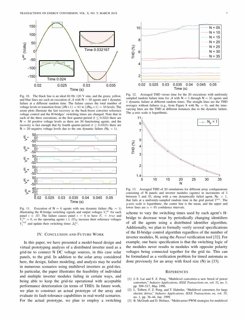
Fig. 10. The black line is an ideal 60 Hz 120 V sine, and the green, yellow,and blue lines are each an execution of A with N = 30 agents and 1 dynamicfailure at a different random time. The failure causes the total number ofvoltage levels to transition from (2N+1) = 61 to (2NO+1) = 59 levels. Thezoom plots illustrate the fast recovery as the buck-boost converter referencevoltage control and the H-bridges’ switching times are changed. Note that ineach of the three executions, in the first quarter-period (t ≤ 0.022) there areN = 30 positive voltage levels as there are 30 functioning agents, and therecovery is fast enough that by fourth quarter-period (t ≥ 0.0325) there areN = 29 negative voltage levels due to the one dynamic failure (NF = 1).
-500
50
V 1dc
-500
50
V 2dc
-500
50
V 3dc
-500
50
V 4dc
-500
50
V 5dc
0.02 0.025 0.03 0.035 0.04 0.045 0.050
2040
V 6dc
Time (s)
Fig. 11. Execution of N = 6 agents with one dynamic failure (NF = 1)illustrating the H-bridge switching signals and output voltages V dc
i for eachpanel i ∈ ID . The failure causes panel i = 6 to have Fi = true andV dci = 0, so the operating agents i ∈ IDO increase their reference voltagesV refi and update their switching times ∆ac
i .
IV. CONCLUSION AND FUTURE WORK
In this paper, we have presented a model-based design andvirtual prototyping analysis of a distributed inverter used as agrid-tie to connect N DC voltage sources, in this case solarpanels, to the grid. In addition to the solar array consideredhere, the design, failure modeling, and analysis may be usefulin numerous scenarios using multilevel inverters as grid-ties.In particular, the paper illustrates the feasibility of individualand multiple inverter modules failing in certain ways, andbeing able to keep the grid-tie operational with acceptableperformance deterioration (in terms of THD). In future work,we plan to construct an actual prototype of the array andevaluate its fault-tolerance capabilities in real-world scenarios.For the actual prototype, we plan to employ a switching
0.02 0.025 0.03 0.035 0.04 0.045 0.05
2
4
6
8
10
Time (s)
THD
(%)
N = 05N = 10N = 15N = 20N = 25N = 30N = 35
Fig. 12. Averaged THD versus time for the 20 executions with uniformlysampled random failure time for A with N = 5 through N = 35 agents and1 dynamic failure at different random times. The straight lines are the THDaverages without failures (e.g., from Figure 8 with NF = 0), and the time-varying lines are the THD at different instances due to the dynamic failure.The y-axis scale is logarithmic.
5 10 15 20 25 30 351.4
2
3
4
5
7
911
N
THD
(%)
NF = 1
Fig. 13. Averaged THD of 20 simulations for different array configurationsconsisting of N panels and inverter modules (agents) in increments of 5between 5 and 35, along with a one dynamically failed agent, NF = 1,that fails at a uniformly-sampled random time in the grid period Tac. They-axis scale is logarithmic, the center line is the mean, and the upper andlower lines are α = 95 confidence intervals.
scheme to vary the switching times used by each agent’s H-bridge to decrease wear by periodically changing identifiersof all the agents using a distributed identifier algorithm.Additionally, we plan to formally verify several specificationsof the H-bridge control algorithm regardless of the number ofinverter modules, N, using the Passel verification tool [32]. Forexample, one basic specification is that the switching logic ofthe modules never results in modules with opposite polarityvoltages being connected together for the grid tie. This canbe formulated as a verification problem for timed automata asdone previously for an array with fixed size (N) in [33].
REFERENCES
[1] J.-S. Lai and F. Z. Peng, “Multilevel converters-a new breed of powerconverters,” Industry Applications, IEEE Transactions on, vol. 32, no. 3,pp. 509–517, May 1996.
[2] L. Tolbert, F. Z. Peng, and T. Habetler, “Multilevel converters for largeelectric drives,” Industry Applications, IEEE Transactions on, vol. 35,no. 1, pp. 36–44, Jan. 1999.
[3] B. McGrath and D. Holmes, “Multicarrier PWM strategies for multilevel

TRANSACTIONS ON ENERGY CONVERSION, VOL. X, NO. Y, MARCH 201X 8
inverters,” Industrial Electronics, IEEE Transactions on, vol. 49, no. 4,pp. 858–867, Aug. 2002.
[4] S. Kjaer, J. Pedersen, and F. Blaabjerg, “A review of single-phase grid-connected inverters for photovoltaic modules,” Industry Applications,IEEE Transactions on, vol. 41, no. 5, pp. 1292–1306, 2005.
[5] L. Franquelo, J. Rodriguez, J. Leon, S. Kouro, R. Portillo, and M. Prats,“The age of multilevel converters arrives,” Industrial Electronics Mag-azine, IEEE, vol. 2, no. 2, pp. 28–39, June 2008.
[6] C. Cecati, F. Ciancetta, and P. Siano, “A multilevel inverter for photo-voltaic systems with fuzzy logic control,” Industrial Electronics, IEEETransactions on, vol. 57, no. 12, pp. 4115–4125, 2010.
[7] B. Johnson, “Control, analysis, and design of distributed inverter sys-tems,” Ph.D. dissertation, University of Illinois at Urbana-Champaign,2013.
[8] F. Filho, L. Tolbert, Y. Cao, and B. Ozpineci, “Real-time selectiveharmonic minimization for multilevel inverters connected to solar panelsusing artificial neural network angle generation,” Industry Applications,IEEE Transactions on, vol. 47, no. 5, pp. 2117–2124, 2011.
[9] C. Turpin, P. Baudesson, F. Richardeau, F. Forest, and T. Meynard,“Fault management of multicell converters,” Industrial Electronics, IEEETransactions on, vol. 49, no. 5, pp. 988–997, Oct. 2002.
[10] A. Chen, L. Hu, L. Chen, Y. Deng, and X. He, “A multilevel convertertopology with fault-tolerant ability,” Power Electronics, IEEE Transac-tions on, vol. 20, no. 2, pp. 405–415, 2005.
[11] F. Chan and H. Calleja, “Reliability: A new approach in design ofinverters for pv systems,” in International Power Electronics Congress,10th IEEE, Oct. 2006, pp. 1–6.
[12] M. Ma, L. Hu, A. Chen, and X. He, “Reconfiguration of carrier-based modulation strategy for fault tolerant multilevel inverters,” PowerElectronics, IEEE Transactions on, vol. 22, no. 5, pp. 2050–2060, Sep.2007.
[13] S. Khomfoi and L. Tolbert, “Fault diagnostic system for a multilevelinverter using a neural network,” Power Electronics, IEEE Transactionson, vol. 22, no. 3, pp. 1062–1069, May 2007.
[14] A. Ristow, M. Begovic, A. Pregelj, and A. Rohatgi, “Development of amethodology for improving photovoltaic inverter reliability,” IndustrialElectronics, IEEE Transactions on, vol. 55, no. 7, pp. 2581–2592, Jul.2008.
[15] P. Lezana, J. Pou, T. Meynard, J. Rodriguez, S. Ceballos, and F. Richard-eau, “Survey on fault operation on multilevel inverters,” IndustrialElectronics, IEEE Transactions on, vol. 57, no. 7, pp. 2207–2218, Jul.2010.
[16] Y. Song and B. Wang, “Survey on reliability of power electronicsystems,” Power Electronics, IEEE Transactions on, vol. 28, no. 1, pp.591–604, Jan. 2013.
[17] S. Harb and R. Balog, “Reliability of candidate photovoltaic module-integrated-inverter (pv-mii) topologies–a usage model approach,” PowerElectronics, IEEE Transactions on, vol. 28, no. 6, pp. 3019–3027, 2013.
[18] Y. Zhao, J. de Palma, J. Mosesian, R. Lyons, and B. Lehman, “Line-line fault analysis and protection challenges in solar photovoltaic arrays,”Industrial Electronics, IEEE Transactions on, vol. 60, no. 9, pp. 3784–3795, 2013.
[19] J. Fischer, S. Gonzalez, M. Herran, M. Judewicz, and D. Carrica,“Calculation-delay tolerant predictive current controller for three-phaseinverters,” Industrial Informatics, IEEE Transactions on, vol. 10, no. 1,pp. 233–242, 2014.
[20] S. Dhople, A. Davoudi, A. Dominguez-Garcia, and P. Chapman, “Aunified approach to reliability assessment of multiphase dc-dc convertersin photovoltaic energy conversion systems,” Power Electronics, IEEETransactions on, vol. 27, no. 2, pp. 739–751, Feb 2012.
[21] S. Bolognani, M. Zordan, and M. Zigliotto, “Experimental fault-tolerantcontrol of a pmsm drive,” Industrial Electronics, IEEE Transactions on,vol. 47, no. 5, pp. 1134–1141, 2000.
[22] X. Kou, K. A. Corzine, and Y. L. Familiant, “Full binary combinationschema for floating voltage source multi-level inverters,” in IndustryApplications Conference, 2002. 37th IAS Annual Meeting. ConferenceRecord of the, vol. 4. IEEE, 2002, pp. 2398–2404.
[23] B. Johnson, P. Krein, and P. Chapman, “Photovoltaic ac module com-posed of a very large number of interleaved inverters,” in AppliedPower Electronics Conference and Exposition (APEC), 2011 Twenty-Sixth Annual IEEE, Mar. 2011, pp. 976–981.
[24] T. Esram and P. Chapman, “Comparison of photovoltaic array maximumpower point tracking techniques,” Energy Conversion, IEEE Transac-tions on, vol. 22, no. 2, pp. 439–449, June 2007.
[25] H. Patel and V. Agarwal, “MATLAB-based modeling to study the effectsof partial shading on PV array characteristics,” Energy Conversion, IEEETransactions on, vol. 23, no. 1, pp. 302–310, Mar. 2008.
[26] M. Ropp and S. Gonzalez, “Development of a MATLAB/Simulinkmodel of a single-phase grid-connected photovoltaic system,” EnergyConversion, IEEE Transactions on, vol. 24, no. 1, pp. 195–202, Mar.2009.
[27] K. Ding, X. Bian, H. Liu, and T. Peng, “A MATLAB-Simulink-basedPV module model and its application under conditions of nonuniformirradiance,” Energy Conversion, IEEE Transactions on, vol. 27, no. 4,pp. 864–872, Dec. 2012.
[28] A. Maki and S. Valkealahti, “Effect of photovoltaic generator compo-nents on the number of MPPs under partial shading conditions,” EnergyConversion, IEEE Transactions on, vol. 28, no. 4, pp. 1008–1017, Dec.2013.
[29] R. Alur, C. Courcoubetis, N. Halbwachs, T. A. Henzinger, P.-H. Ho,X. Nicollin, A. Olivero, J. Sifakis, and S. Yovine, “The algorithmicanalysis of hybrid systems,” Theoretical Computer Science, vol. 138,no. 1, pp. 3–34, 1995.
[30] N. Lynch, R. Segala, and F. Vaandrager, “Hybrid I/O automata,” Infor-mation and Computation, vol. 185, no. 1, pp. 105–157, 2003.
[31] D. K. Kaynar, N. Lynch, R. Segala, and F. Vaandrager, The Theoryof Timed I/O Automata, ser. Synthesis Lectures in Computer Science.Morgan & Claypool, 2006.
[32] T. T. Johnson, “Uniform verification of safety for parameterized net-works of hybrid automata,” Ph.D. dissertation, University of Illinois atUrbana-Champaign, Urbana, IL 61801, 2013.
[33] T. T. Johnson, Z. Hong, and A. Kapoor, “Design verification methodsfor switching power converters,” in Power and Energy Conference atIllinois (PECI), 2012 IEEE, Feb. 2012, pp. 1–6.
[34] S. Hossain, S. Dhople, and T. T. Johnson, “Reachability analysis ofclosed-loop switching power converters,” in Power and Energy Confer-ence at Illinois (PECI), 2013, pp. 130–134.
[35] L. V. Nguyen and T. T. Johnson, “Benchmark: Dc-to-dc switched-modepower converters (buck converters, boost converters, and buck-boostconverters),” in Applied Verification for Continuous and Hybrid SystemsWorkshop (ARCH 2014), Berlin, Germany, Apr. 2014.
[36] M. Althoff, “Formal and compositional analysis of power systems usingreachable sets,” Power Systems, IEEE Transactions on, no. 99, pp. 1–11,2014.
[37] T. T. Johnson, S. Mitra, and K. Manamcheri, “Safe and stabilizingdistributed cellular flows,” in Proceedings of the 30th IEEE InternationalConference on Distributed Computing Systems (ICDCS). Genoa, Italy:IEEE, June 2010.
[38] T. T. Johnson and S. Mitra, “Safe flocking in spite of actuator faultsusing directional failure detectors,” Journal of Nonlinear Systems andApplications, vol. 2, no. 1-2, pp. 73–95, Apr. 2011.
[39] N. A. Lynch, Distributed Algorithms. San Francisco, CA, USA: MorganKaufmann Publishers Inc., 1996.
[40] R. P. Severns and G. Bloom, Modern DC-to-DC Switchmode PowerConverter Circuits. New York, New York: Van Nostrand ReinholdCompany, 1985.
[41] R. W. Erickson and D. Maksimovic, Fundamentals of Power Electronics,2nd ed. Springer, 2004.
PLACEPHOTOHERE
Luan Viet Nguyen Biography to be added in a finalversion if accepted.

TRANSACTIONS ON ENERGY CONVERSION, VOL. X, NO. Y, MARCH 201X 9
PLACEPHOTOHERE
Taylor T Johnson Biography to be added in a finalversion if accepted.