Trane Variable Speed ComfortLink II Air Conditioners 4TTV0 · Variable Speed ComfortLink ™II Air...
12
November 2014 22-1895-1A-EN Variable Speed ComfortLink™II Air Conditioners 4TTV0024A1000A 4TTV0036B1000A 4TTV0048A1000A 4TTV0060A1000A 4TTV0061A1000A Note: “Graphics in this document are for representation only. Actual model may differ in appearance.” Product Data
Transcript of Trane Variable Speed ComfortLink II Air Conditioners 4TTV0 · Variable Speed ComfortLink ™II Air...
November 2014 22-1895-1A-EN
Variable SpeedComfortLink™™IIAir Conditioners
4TTV0024A1000A
4TTV0036B1000A
4TTV0048A1000A
4TTV0060A1000A
4TTV0061A1000A
NNoottee:: “Graphics in this document are for representationonly. Actual model may differ in appearance.”
Product Data
2 22-1895-1A-EN
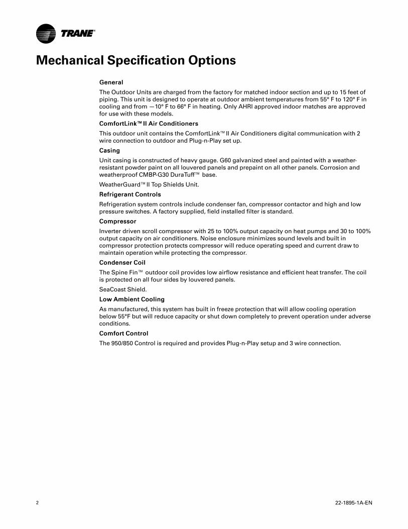
Mechanical Specification Options
GGeenneerraall
The Outdoor Units are charged from the factory for matched indoor section and up to 15 feet of
piping. This unit is designed to operate at outdoor ambient temperatures from 55° F to 120° F in
cooling and from —10° F to 66° F in heating. Only AHRI approved indoor matches are approved
for use with these models.
CCoommffoorrttLLiinnkk™™IIII AAiirr CCoonnddiittiioonneerrss
This outdoor unit contains the ComfortLink™II Air Conditioners digital communication with 2
wire connection to outdoor and Plug-n-Play set up.
CCaassiinngg
Unit casing is constructed of heavy gauge. G60 galvanized steel and painted with a weather-
resistant powder paint on all louvered panels and prepaint on all other panels. Corrosion and
weatherproof CMBP-G30 DuraTuff™ base.
WeatherGuard™II Top Shields Unit.
RReeffrriiggeerraanntt CCoonnttrroollss
Refrigeration system controls include condenser fan, compressor contactor and high and low
pressure switches. A factory supplied, field installed filter is standard.
CCoommpprreessssoorr
Inverter driven scroll compressor with 25 to 100% output capacity on heat pumps and 30 to 100%
output capacity on air conditioners. Noise enclosure minimizes sound levels and built in
compressor protection protects compressor will reduce operating speed and current draw to
maintain operation while protecting the compressor.
CCoonnddeennsseerr CCooiill
The Spine Fin™ outdoor coil provides low airflow resistance and efficient heat transfer. The coil
is protected on all four sides by louvered panels.
SeaCoast Shield.
LLooww AAmmbbiieenntt CCoooolliinngg
As manufactured, this system has built in freeze protection that will allow cooling operation
below 55°F but will reduce capacity or shut down completely to prevent operation under adverse
conditions.
CCoommffoorrtt CCoonnttrrooll
The 950/850 Control is required and provides Plug-n-Play setup and 3 wire connection.

22-1895-1A-EN 3
Product Specifications
Air Conditioner Models
OUTDOOR UNIT (a) (b) 4TTV0024A1000A 4TTV0036B1000A 4TTV0048A1000A
POWER CONNS.— V/PH/HZ (c) 208/230/1/60 208/230/1/60 208/230/1/60
MIN. BRCH. CIR. AMPACITY 17.0 18.0 23.0
BR. CIR. PROT. RTG.— MAX. (AMPS) 25 25 35
COMPRESSOR SCROLL SCROLL SCROLL
NO. USED— NO. SPEEDS 1–VARIABLE 1–VARIABLE 1–VARIABLE
R.L. AMPS (d)— L.R. AMPS 11.5 — 10.2 12.4 — 10.2 16.0 — 12.0
FACTORY INSTALLED
START COMPONENTS (e) NA NA NA
INSULATION/SOUND BLANKET YES YES YES
COMPRESSOR HEAT YES YES YES
OUTDOOR FAN
DIA. (IN.) — NO. USED 23— 1 23— 1 27.5 — 1
TYPE DRIVE — NO. SPEEDS DIRECT— VARIABLE DIRECT— VARIABLE DIRECT— VARIABLE
CFM@ 0.0 IN. W.G. (f) 2680 2850 4560
NO. MOTORS— HP 1— 1/3 1 — 1/3 1 — 1/3
MOTOR SPEED R.P.M. 200 — 1200 200 — 1200 200 — 1200
VOLTS/PH/HZ 208/230/1/60 208/230/1/60 208/230/1/60
F.L. AMPS 2.8 2.8 2.8
OUTDOOR COIL — TYPE SPINE FIN™ SPINE FIN™ SPINE FIN™
ROWS— F.P.I. 1 — 24 1 — 24 1 — 24
FACE AREA (SQ. FT.) 19.77 23.75 27.87
TUBE SIZE (IN.) 3/8 3/8 3/8
REFRIGERANT R410–A R410–A R410–A
LBS.— R-410A (O.D. UNIT) (g) 7 lb — 6 oz 9lb — 6 oz 11 lb — 1 oz
FACTORY SUPPLIED YES YES YES
LINE SIZE — IN. O.D. GAS 5/8 (h) 3/4 (h) 7/8 (h)
LINE SIZE — IN. O.D. LIQ. (h) 3/8 3/8 3/8
CHARGING SPECIFICATIONS
SUBCOOLING 10° 10° 10°
DIMENSIONS H XW X D H XW X D H XW X D
CRATED (IN.) 51.6 X 30.1 X 33 53.4 X 35.1 X 38.7 53.4 X 35.1 X 38.7
WEIGHT
SHIPPING (LBS.) 228 263 285
NET (LBS.) 207 239 259
(a) Certified in accordance with the Air-Source Unitary Air-conditioner Equipment certification program, which is based on AHRI standard 210/240.(b) Rated in accordance with AHRI standard 270.(c) Calculated in accordance with Natl. Elec. Codes. Use only HACR circuit breakers or fuses.(d) This value shown for compressor RLA on the unit nameplate and on this specification sheet is used to compute minimum branch circuit ampacity and max.
fuse size. The value shown is the branch circuit selection current.(e) NA means no start components. Yes means quick start kit components. PTC means positive temperature coefficient starter.(f) Standard Air — Dry Coil — Outdoor(g) This value approximate. For more precise value see unit nameplate.(h) Max. linear length 150 ft.; Max. lift — Suction 50 ft.; Max. lift — Liquid 50 ft. .

4 22-1895-1A-EN
Air Conditioner Models
OUTDOOR UNIT (a) (b) 4TTV0060A1000A 4TTV0061A1000A
POWER CONNS.— V/PH/HZ (c) 208/230/1/60 208/230/1/60
MIN. BRCH. CIR. AMPACITY 27.0 27.0
BR. CIR. PROT. RTG.— MAX. (AMPS) 40 40
COMPRESSOR SCROLL SCROLL
NO. USED— NO. SPEEDS 1–VARIABLE 1–VARIABLE
R.L. AMPS (d)— L.R. AMPS 19.3 — 12.0 19.3 — 12.0
FACTORY INSTALLED
START COMPONENTS (e) NA NA
INSULATION/SOUND BLANKET YES YES
COMPRESSOR HEAT YES YES
OUTDOOR FAN
DIA. (IN.) — NO. USED 27.5 — 1 27.5 — 1
TYPE DRIVE — NO. SPEEDS DIRECT— VARIABLE DIRECT— VARIABLE
CFM@ 0.0 IN. W.G. (f) 4787 4780
NO. MOTORS— HP 1— 1/3 1 — 1/3
MOTOR SPEED R.P.M. 200 — 1200 200 — 1200
VOLTS/PH/HZ 208/230/1/60 208/230/1/60
F.L. AMPS 2.8 2.8
OUTDOOR COIL — TYPE SPINE FIN™ SPINE FIN™
ROWS— F.P.I. 1 — 24 2 — 24
FACE AREA (SQ. FT.) 30.80 30.80
TUBE SIZE (IN.) 3/8 3/8
REFRIGERANT R410–A R410–A
LBS.— R-410A (O.D. UNIT) (g) 11 lb — 14 oz 12 lb — 7 oz
FACTORY SUPPLIED YES YES
LINE SIZE — IN. O.D. GAS 1–1/8 (h) 1–1/8 (i)
LINE SIZE — IN. O.D. LIQ. (h) 3/8 3/8
CHARGING SPECIFICATIONS
SUBCOOLING 10° 7.5°
DIMENSIONS H XW X D H XW X D
CRATED (IN.) 57.4 X 35.1 X 38.7 57.4 X 35.1 X 38.7
WEIGHT
SHIPPING (LBS.) 299 329
NET (LBS.) 273 303
(a) Certified in accordance with the Air-Source Unitary Air-conditioner Equipment certification program, which is based on AHRI standard 210/240.(b) Rated in accordance with AHRI standard 270.(c) Calculated in accordance with Natl. Elec. Codes. Use only HACR circuit breakers or fuses.(d) This value shown for compressor RLA on the unit nameplate and on this specification sheet is used to compute minimum branch circuit ampacity and max.
fuse size. The value shown is the branch circuit selection current.(e) NA means no start components. Yes means quick start kit components. PTC means positive temperature coefficient starter.(f) Standard Air — Dry Coil — Outdoor(g) This value approximate. For more precise value see unit nameplate.(h) Max length of refrigerant lines from outdoor to indoor unit MUST NOTexceed 80 feet. The max vertical change MUST NOTexceed 25 feet. See footnote (h)
if 7/8" suction line is used.(i) Max length of refrigerant lines from outdoor to indoor unit MUST NOTexceed 80 feet. The max vertical change MUST NOTexceed 25 feet. See footnote (h)
if 7/8" suction line is used.
PPrroodduucctt SSppeecciiffiiccaattiioonnss
22-1895-1A-EN 5
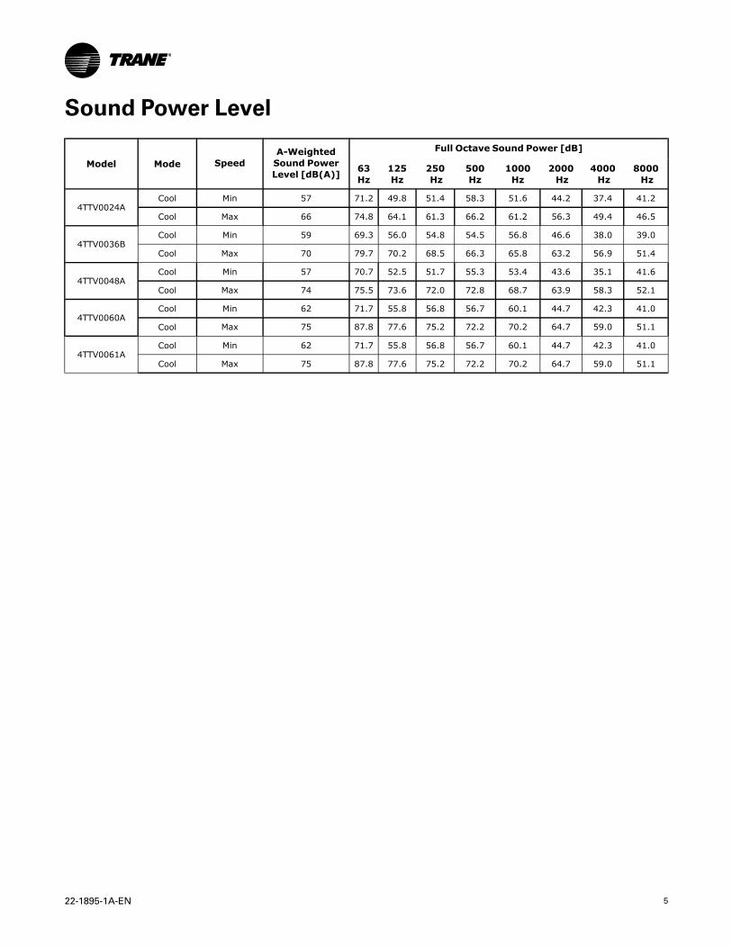
Sound Power Level
Model Mode SpeedA-WeightedSound PowerLevel [dB(A)]
Full Octave Sound Power [dB]
63Hz
125Hz
250Hz
500Hz
1000Hz
2000Hz
4000Hz
8000Hz
4TTV0024ACool Min 57 71.2 49.8 51.4 58.3 51.6 44.2 37.4 41.2
Cool Max 66 74.8 64.1 61.3 66.2 61.2 56.3 49.4 46.5
4TTV0036BCool Min 59 69.3 56.0 54.8 54.5 56.8 46.6 38.0 39.0
Cool Max 70 79.7 70.2 68.5 66.3 65.8 63.2 56.9 51.4
4TTV0048ACool Min 57 70.7 52.5 51.7 55.3 53.4 43.6 35.1 41.6
Cool Max 74 75.5 73.6 72.0 72.8 68.7 63.9 58.3 52.1
4TTV0060ACool Min 62 71.7 55.8 56.8 56.7 60.1 44.7 42.3 41.0
Cool Max 75 87.8 77.6 75.2 72.2 70.2 64.7 59.0 51.1
4TTV0061ACool Min 62 71.7 55.8 56.8 56.7 60.1 44.7 42.3 41.0
Cool Max 75 87.8 77.6 75.2 72.2 70.2 64.7 59.0 51.1

6 22-1895-1A-EN
Optional Accessories:Model 4TTV0024A 4TTV0036B 4TTV0048A 4TTV0060A 4TTV0061A
Rubber IsolatorKit
BAYISLT101 BAYISLT101 BAYISLT101 BAYISLT101 BAYISLT101
Snow Leg — Base& Cap 4” High BAYLEGS002 BAYLEG2002 BAYLEGS002 BAYLEGS002 BAYLEGS002
Snow Leg — 4”Extension
BAYLEGS003 BAYLEGS003 BAYLEGS003 BAYLEGS003 BAYLEGS003
ExtremeConditionMounting Kit
BAYECMT023 BAYECMT004 BAYECMT004 BAYECMT004 BAYECMT004
VerticalDischarge Air Kit BAYVDTA003 BAYVDTA004 BAYVDTA004 BAYVDTA004 BAYVDTA004
RefrigerantLineset
TAYREFLN9(a) TAYREFLN7(a) TAYREFLN3(a) TAYREFLN3(a) TAYREFLN3(a)
(a) Consult handbook for available length options.
General DataAAHHRRII SSTTAANNDDAARRDD 221100//224400 RRAATTIINNGG CCOONNDDIITTIIOONNSS
• Cooling 80°F DB, 67°F WB air entering indoor coil, 95°F DB air entering outdoor coil.
• High Temperature Heating 47°F DB, 43°F WB air entering outdoor coil, 70°F DB entering
indoor coil.
• Low Temperature Heating 17°F DB, 15°F WB air entering outdoor coil, 70°F DB air entering
indoor coil.
• Rated indoor airflow for heating is the same as for cooling.
AAHHRRII SSTTAANNDDAARRDD 227700 RRAATTIINNGG CCOONNDDIITTIIOONNSS— (Noise rating numbers are determined with the
unit in cooling operation) Standard Noise Rating number is at 95°F outdoor air.

22-1895-1A-EN 7
Model Nomenclature
Refrigerant Type2 = R-224 = R-410A
TRANE
Product TypeW = Split Heat P umpT = Split Cooling
Product FamilyV = Variable Speed M or B = BasicZ = Leadership – Two Stage A = Light CommercialX = LeadershipR = Replacement/R etail
Family SEER3 = 13 6 = 16 0 = 204 = 14 8 = 18 5 = 15 9 = 19
Split S ystem Connections 1 -6 Tons0 = Brazed
Nominal Capacity in 0 00s of BTUs
Major Design Modifications
Power Supply1 = 200-230/1/60 or 208-230/1/603 = 200-230/3/604 = 460/3/60
Secondary Function
Minor Design Modifications
Unit Parts Identifier
Outdoor Units 4 T W V 0 0 3 6 A 1 0 0 0 A A
T U H 1 B 0 8 0 A C V 3 V A A
E = 80% Induced Draft StandardD = 80% Induced Draft PremiumC = 90% Condensing Stand ardX = 90% Condensing Prem iumH = 95% Condensing Prem ium
Number of Heating Stages1 = Single Stage2 = Two Stage3 = Three StageM = Mod ulating
Major D esign Change
Mino r Design Chang e
Service Digit - Not Or derable
Heating Inp ut in 100 0’s (BTUH)080 = 80,000 BTUH
Cabinet WidthA = 14.5" Cabinet WidthB = 17.5" Cabinet WidthC = 21.0" Cabinet WidthD = 24.5" Cabinet Width
Air Capacity f or CoolingStandard PSC High Ef ficiency24 = 2 Tons V3 = 3 Tons H3 = 3 Tons36 = 3 Tons V4 = 4 Tons H4 = 4 Tons42 = 3.5 Tons V5 = 5 Tons H5 = 5 Tons45 = 4 Tons48 = 4 Tons54 = 5 Tons60 = 5 Tons72 = 6 Tons
Voltage9 = 115 Volts / 60 Hertz / Natural GasA = 115 Volts / 50 Hertz / Natural GasC = 115 Volts / Natural Gas with Com municating System ControlF = 115 Volts / Natural Gas with Integrated E lectronic FilterD = 115 Volts / Natural Gas with Com municating System Control and Integrated E lectronic Filter
Draft Inducer Speeds1 = Single Speed2 = V = Variable Speed
Furnace ConfigurationTU = Upflow/Ho rizontalTD = Dow nflow/Hor izontal
Type
Variable Speed
Two Speed
T A M 8 C 0 B 3 6 V 3 1 C A A
BrandT = TraneG = Good (Trane Branded)
Product TypeA = Air Handler
Product Tier2 = Good, Entry Level Feature Set4 = Better, Retail Replacement Mid Effy5 = Better, Entry Level High Effy., Multi-Speed7 = Best, Retail Replacement High Effy 8 = Best, Retail Ultimate High Effy Variable-Speed
Major Design Chang e
Minor Design Change
Unit Parts Identifier
Airflo w Type & CapabilityS = Low Effy PSC, 1-5 - nom.M = Mid Effy Mu lti-Speed, 1-5 - nom.H = High Effy Mu lti-Speed, 1-5 - nom.V = High Effy Variable, 1-5 - nom.
No Descriptor0 = Air Handler / Coil
System Control TypeS = Standard - 24 VACC = CLII 13.8 VDC
Size (Footprint)A = 17.5 x 21.5B = 21.0 x 21.5C = 23.5 x 21.5
Cooling Size: Air Handler or Coil0-9 = AH Coil - 1000 BTU’s (18, 24, 30, 36, 42, 48, 60)
Power Supply1 = 208-230/1/60
Conver tabilityM = Multi-poise 4-wayF = Upflow Front Return , 3-way T = 3-way
Air Handler
4 T X C B 0 3 6 A C 3 H C A A
SeriesT = Premium N = Premium
(Heat Pump
C = Standard (Convertible to HP)
Refrigerant Type4 = R-410A
Coil DesignX = Direct Expansion Ev aporator Coil
Coil FeatureC = Cased A CoilA = Uncased A CoilF = Cased Hor izontal Flat Coil
Coil Width (Cased/Uncased)A = 14.5" /13.3"B = 17.5" / 16.3"C = 21.0" / 19.8"D = 24.5" / 23.3"H = 10.5"
Refrigerant Line Coupling0 = Brazed
Nominal Capacity in 1000's (BTUH)
Major Design Chang e
Efficienc yC = StandardS = Hi Efficiency (der ived from 10 SEER produ cts)
Refrigerant Control3 = TXV - Non-Bleed
Coil Cir cuitr yH = Heat PumpC = Cooling
Airflo w ConfigurationA = Upflow OnlyU = Upflow/DownflowH = Hor izontal OnlyC = Convertible - Upflow Downflow Left or Right Airflow
Minor Design Change
Service Digit - Not Orderable
Heat Pump/Cooling Coils
Gas Furnaces
Tonnage (cfm/ton)Tonnage (cfm/ton)
Tonnage (cfm/ton)
Tonnage (cfm/ton)
8 22-1895-1A-EN
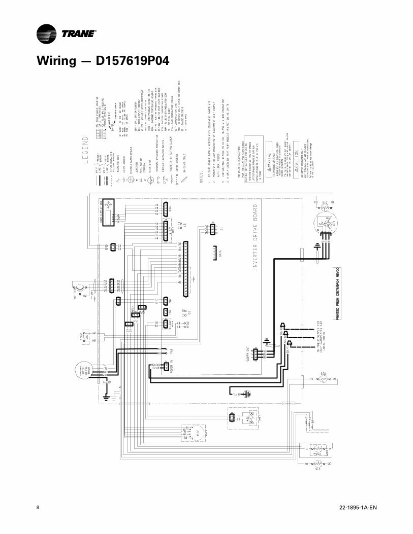
Wiring — D157619P04
23
1 13
2

22-1895-1A-EN 9
NNootteess
10 22-1895-1A-EN
NNootteess

22-1895-1A-EN 11
NNootteess
NNootteess
Trane optimizes the performance of homes and buildings around the world. A business of Ingersoll Rand, the leader in
creating and sustaining safe, comfortable and energy efficient environments, Trane offers a broad portfolio of advanced
controls and HVAC systems, comprehensive building services, and parts. For more information, visit www.Trane.com.
Trane has a policy of continuous product and product data improvements and reserves the right to change design and specifications without notice.
©2014 Trane
22-1895-1A-EN 17 Nov 2014
Supersedes 22-1895-1-EN (September 2013)