ASK-EHS Company Introduction | Safety Services | EHS/HSE Consultants
Revision: 06 August 2016 Page 1 of 29
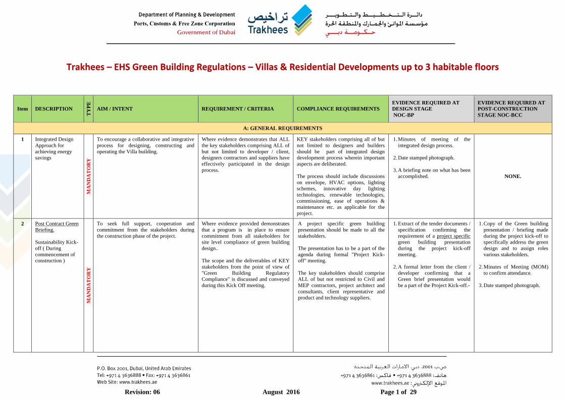
Trakhees – EHS Green Building Regulations – Villas & Residential Developments up to 3 habitable floors
Item DESCRIPTION
TY
PE
AIM / INTENT REQUIREMENT / CRITERIA COMPLIANCE REQUIREMENTS
EVIDENCE REQUIRED AT
DESIGN STAGE
NOC-BP
EVIDENCE REQUIRED AT
POST-CONSTRUCTION
STAGE NOC-BCC
A: GENERAL REQUIREMENTS
1 Integrated Design
Approach for
achieving energy savings
MA
ND
AT
OR
Y
To encourage a collaborative and integrative
process for designing, constructing and
operating the Villa building.
Where evidence demonstrates that ALL
the key stakeholders comprising ALL of
but not limited to developer / client, designers contractors and suppliers have
effectively participated in the design
process.
KEY stakeholders comprising all of but
not limited to designers and builders
should be part of integrated design development process wherein important
aspects are deliberated.
The process should include discussions
on envelope, HVAC options, lighting schemes, innovative day lighting
technologies, renewable technologies,
commissioning, ease of operations & maintenance etc. as applicable for the
project.
1. Minutes of meeting of the
integrated design process.
2. Date stamped photograph.
3. A briefing note on what has been accomplished. NONE.
2 Post Contract Green
Briefing.
Sustainability Kick-
off ( During
commencement of construction )
MA
ND
AT
OR
Y
To seek full support, cooperation and
commitment from the stakeholders during
the construction phase of the project.
Where evidence provided demonstrates
that a program is in place to ensure
commitment from all stakeholders for site level compliance of green building
design..
The scope and the deliverables of KEY
stakeholders from the point of view of
"Green Building Regulatory Compliance" is discussed and conveyed
during this Kick Off meeting.
A project specific green building
presentation should be made to all the
stakeholders.
The presentation has to be a part of the
agenda during formal "Project Kick-off" meeting.
The key stakeholders should comprise ALL of but not restricted to Civil and
MEP contractors, project architect and
consultants, client representative and
product and technology suppliers.
1. Extract of the tender documents /
specification confirming the
requirement of a project specific green building presentation
during the project kick-off
meeting.
2. A formal letter from the client /
developer confirming that a Green brief presentation would
be a part of the Project Kick-off.-
1. Copy of the Green building
presentation / briefing made
during the project kick-off to specifically address the green
design and to assign roles
various stakeholders.
2. Minutes of Meeting (MOM)
to confirm attendance.
3. Date stamped photograph.

Revision: 06 August 2016 Page 2 of 29
Item DESCRIPTION
TY
PE
AIM / INTENT REQUIREMENT / CRITERIA COMPLIANCE REQUIREMENTS
EVIDENCE REQUIRED AT
DESIGN STAGE
NOC-BP
EVIDENCE REQUIRED AT
POST-CONSTRUCTION
STAGE NOC-BCC
B: ENVELOPE & ENERGY
1 Compliance with Thermal Insulation
System and Best Practices Energy
conservation
methods
[For both Air-
conditioned and Non Air-
Conditioned
buildings.]
MA
ND
AT
OR
Y
To reduce/control the solar heat gain through windows.
To reduce conductive heat gain through
opaque elements into the occupied space
To encourage villa developments to achieve
increased levels of performance. Sound
design principles focusing on the insulation minimizes the environmental impact and
thereby CO2 emissions associated with their
operational energy consumption.
Excessive heat gain increases the
temperature within the space causing discomfort to the occupants. It also Increases
the capacity of the HVAC equipment
required to cater to this additional heat load being added to the space. Alongside,
equipment sized higher consumes greater
energy during their operations and may require greater maintenance.
Where evidence provided demonstrates an improvement in the energy efficiency
of the building's fabric and services and therefore achieves lower building
operational related CO2 emissions. The
envelope addresses the following
1) Roofs
2) Walls 3) Slab
4) Door
5) Vertical Glazing 6) Skylight
All Villas should be designed to achieve the environmental parameters (U-values,
Solar heat gain coefficients, etc.) for various components of the building
Fabric/ Envelope as mentioned in Table-
1 of the Annexure that is part of the
Regulation.
1. Specification documents stating types of glazing, roof and wall
insulation.
2. Calculations demonstrating
average U-values and other
thermal characteristics specified
for the project.
3. Typical sections of the envelope
for both conditioned and non-
conditioned spaces.
4. These Envelope values must be
used in the heat load estimation and sizing of the AC Equipment.
Accordingly the heat load
estimate should demonstrate these inputs.
5. The Envelope details MUST be confirmed by filling the envelope
commitment sheet of part of the
GBF-09 submission booklet.
1. As-Built envelope details i.e. glazing, roof and wall to
confirm compliance to design values. These must be
reflected in the submission
booklet
2. Contractor’s material data
sheets for the envelope elements.
3. Date stamped photographic evidence as applicable.
NOTE: For specific situations, the compliance to these specific
requirements may be required to
be physically verified during the final check.
2
Limiting / Reversing Thermal Bridges
[Continuous Insulation /
Associated
Strategies]
MA
ND
AT
OR
Y
To minimize the thermal bridges and
maximize the Insulations' effectiveness between the enclosed space (Interior) and
external (ambient) space through careful
design and good construction practices.
Heat flow through conductive components in
an otherwise well-insulated assembly, results in disproportionately significant heat gain
into the space.
Thermal Bridges in a building can be
expensive and cost prohibitive besides
causing excessive heat gain and in some cases condensation as well.
Where evidence provided demonstrates
that continuity of the thermal insulation is achieved to the practical extent
possible
Where thermal bridges do occur, care
should be taken to minimize their effects
right at the design stage through proper design review.
All Insulating building components
must be designed and installed to work in unison and create a continuous barrier
to heat flow in the building envelope.
The insulation should be reviewed in relation to
Its location within the walls and Roofs
Its interface / connectivity with surrounding or penetration
materials
Connectivity within and between
insulating components.
1. Statement on strategies adopted
to reduce Thermal bridging.
2. Supporting documents such as
drawings / extract of specifications to demonstrate
such strategy.
1. As Built drawings showing
the strategies followed on site for limiting the thermal
bridging.
2. Date stamped site
photographs where relevant.
Revision: 06 August 2016 Page 3 of 29
Item DESCRIPTION
TY
PE
AIM / INTENT REQUIREMENT / CRITERIA COMPLIANCE REQUIREMENTS
EVIDENCE REQUIRED AT
DESIGN STAGE
NOC-BP
EVIDENCE REQUIRED AT
POST-CONSTRUCTION
STAGE NOC-BCC
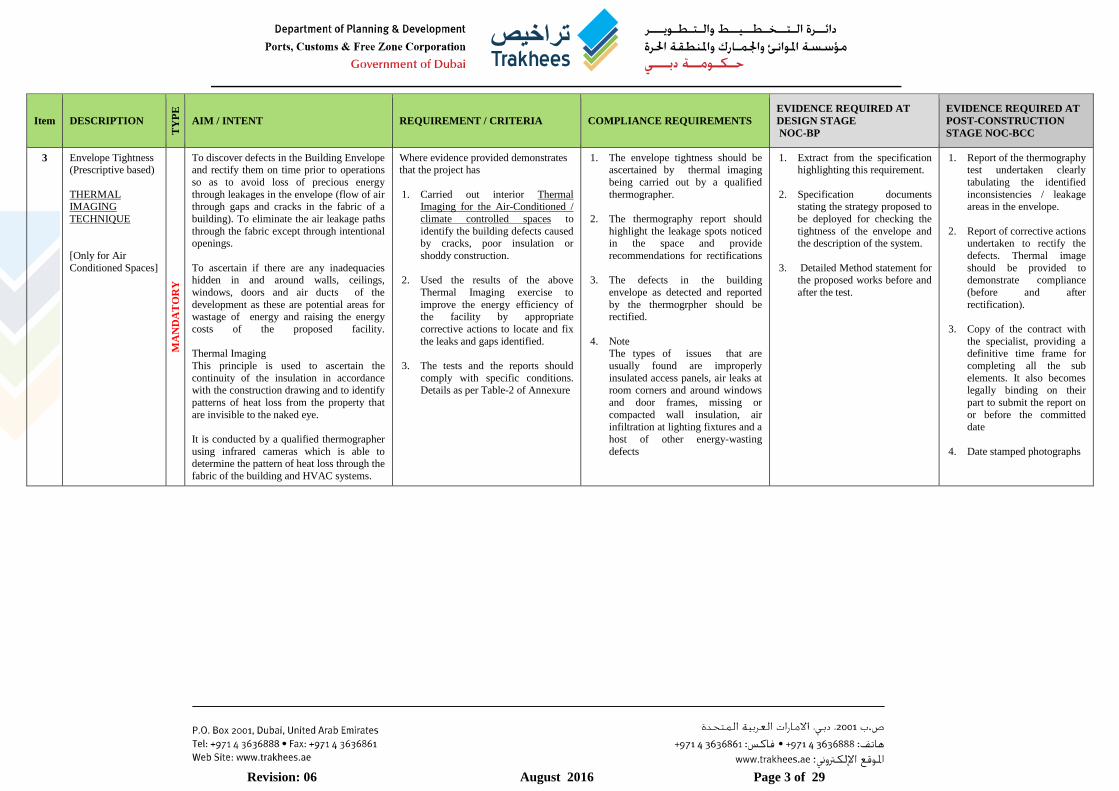
3 Envelope Tightness (Prescriptive based)
THERMAL IMAGING
TECHNIQUE
[Only for Air
Conditioned Spaces]
MA
ND
AT
OR
Y
To discover defects in the Building Envelope and rectify them on time prior to operations
so as to avoid loss of precious energy
through leakages in the envelope (flow of air through gaps and cracks in the fabric of a
building). To eliminate the air leakage paths
through the fabric except through intentional openings.
To ascertain if there are any inadequacies hidden in and around walls, ceilings,
windows, doors and air ducts of the
development as these are potential areas for wastage of energy and raising the energy
costs of the proposed facility.
Thermal Imaging
This principle is used to ascertain the
continuity of the insulation in accordance with the construction drawing and to identify
patterns of heat loss from the property that
are invisible to the naked eye.
It is conducted by a qualified thermographer
using infrared cameras which is able to determine the pattern of heat loss through the
fabric of the building and HVAC systems.
Where evidence provided demonstrates that the project has
1. Carried out interior Thermal Imaging for the Air-Conditioned /
climate controlled spaces to
identify the building defects caused by cracks, poor insulation or
shoddy construction.
2. Used the results of the above
Thermal Imaging exercise to
improve the energy efficiency of the facility by appropriate
corrective actions to locate and fix
the leaks and gaps identified.
3. The tests and the reports should
comply with specific conditions. Details as per Table-2 of Annexure
1. The envelope tightness should be ascertained by thermal imaging
being carried out by a qualified
thermographer.
2. The thermography report should
highlight the leakage spots noticed in the space and provide
recommendations for rectifications
3. The defects in the building
envelope as detected and reported
by the thermogrpher should be rectified.
4. Note The types of issues that are
usually found are improperly
insulated access panels, air leaks at room corners and around windows
and door frames, missing or
compacted wall insulation, air
infiltration at lighting fixtures and a
host of other energy-wasting
defects
1. Extract from the specification highlighting this requirement.
2. Specification documents stating the strategy proposed to
be deployed for checking the
tightness of the envelope and the description of the system.
3. Detailed Method statement for the proposed works before and
after the test.
1. Report of the thermography test undertaken clearly
tabulating the identified
inconsistencies / leakage areas in the envelope.
2. Report of corrective actions undertaken to rectify the
defects. Thermal image
should be provided to demonstrate compliance
(before and after
rectification).
3. Copy of the contract with
the specialist, providing a definitive time frame for
completing all the sub
elements. It also becomes legally binding on their
part to submit the report on
or before the committed
date
4. Date stamped photographs

Revision: 06 August 2016 Page 4 of 29
Item DESCRIPTION
TY
PE
AIM / INTENT REQUIREMENT / CRITERIA COMPLIANCE REQUIREMENTS
EVIDENCE REQUIRED AT
DESIGN STAGE
NOC-BP
EVIDENCE REQUIRED AT
POST-CONSTRUCTION
STAGE NOC-BCC
4 Envelope Tightness (Performance based)
BLOWER DOOR TEST TECHNIQUE
VO
LU
NT
AR
Y
To discover defects in the Building Envelope and rectify them on time prior to operations
so as to avoid loss of precious energy
through leakages in the envelope (flow of air through gaps and cracks in the fabric of a
building)
To ascertain if there are any inadequacies
hidden in and around walls, ceilings,
windows, doors and air ducts of the development as these are potential areas for
wastage of energy and rising energy costs of
the proposed facility.
Subjecting the development to blower door
testing which is a diagnostic tool to measure how much infiltration is occurring in the
built facility.
Where evidence provided demonstrates that the building / facility
1. has installed an airtight envelope;
2. has taken the measures to identify
the defects / leakages in the envelope by subjecting it to door
blower test
3. The air leakage is contained within
maximum of 10m3/hr /m2 @ 50
Pascal.
4. Details as per Table-2
The principal contractor accounts for the door blower test within the programme
of works and this comprises at a
minimum the following tasks:
1. Setting up the blower door.
2. Preparing the building for the Pre b
lower door test.
3. Performing the blower door test.
4. Recording the results on
performance testing form
5. Reporting the result to the
contractor.
These test need to be conducted with
the use of a blower door to measure the amount of leakage of an object (thereby
ascertaining the envelope tightness)
which can in turn be extended with the use of techniques such as thermography
and smoke simulations to locate any
excessive leakages.
1. Specification documents stating the strategy proposed to
be deployed for checking the
tightness of the envelope, the description of the system and
the numerical values proposed
to be met.
2. Detailed method statement by
the appointed specialist
3. Copy of the contract / purchase
order to support the appointment of the specialist
for the subject work
1. Test Report demonstrating compliance / corrective
actions undertaken to seal the
envelope. The report should include all of but not limited
to the following
a. Executive summary of the
air tightness test
b. Test objective
c. Test Methodology
d. Test details
e. Formal test Report –
Positive pressurisation test
f. Test Envelope description
and Fan diagram
g. .Date stamped Photographs
as evidence.
2. Copy of the contract with the
specialist, providing a
definitive time frame for
completing all the sub
elements. It also becomes legally binding on their part
to submit the report on or
before the committed date.
5 Efficient SIZING of
the HVAC systems
MA
ND
AT
OR
Y
To encourage optimum use of resources by
an Engineering approach to sizing and selection of HVAC equipment and systems.
To Reduce Cooling loads and Energy use of the facility.
Where evidence provided demonstrates
that the equipment and systems have been selected after carrying out proper
engineering calculation in line with the
internationally accepted practices.
Heat load calculations should be carried
out for all the conditioned areas of the building and the results of these
calculations should be used as the basis
for selecting the Air-conditioning equipment.
Where heat recovery units are being used, a proper ventilation calculations
should be carried out (areas such as
kitchen, toilet etc. requiring ventilation) and the results of such calculations
should be used for sizing the fresh air
systems, exhaust systems and Energy Recovery Units etc.
1. Heat load calculations for
conditioned area incorporating the right envelope thermal
characteristics ( as confirmed
in point 1)
2. Fresh air / ventilation
calculation.
3. Schedule of equipment with
the capacities
4. Confirmation of air balance for
energy recovery system
1. Technical submittals /
material data sheets for the installed equipment.
2. Date stamped photograph.
Revision: 06 August 2016 Page 5 of 29
Item DESCRIPTION
TY
PE
AIM / INTENT REQUIREMENT / CRITERIA COMPLIANCE REQUIREMENTS
EVIDENCE REQUIRED AT
DESIGN STAGE
NOC-BP
EVIDENCE REQUIRED AT
POST-CONSTRUCTION
STAGE NOC-BCC
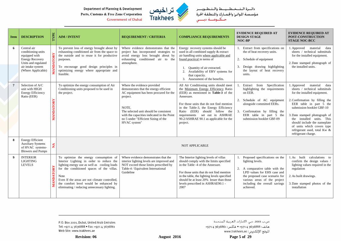
6 Central air conditioning units
equipped with
Energy Recovery Units and regulated
air intake system
(Where Applicable)
MA
ND
AT
OR
Y
To prevent loss of energy brought about by exhausting conditioned air from the space to
the outside and to reuse it for productive
purposes.
To encourage good design principles in
optimizing energy where appropriate and feasible.
Where evidence demonstrates that the project has incorporated strategies to
avoid energy loss brought about by
exhausting conditioned air to the atmosphere.
Energy recovery systems should be used in all combined supply & extract
air handling units where applicable and
found practical in terms of
1. Quantity of air extracted.
2. Availability of ERV systems for
that capacity.
3. Assessment of the benefits.
1. Extract from specifications on the of heat recovery units.
2. Schedule of equipment
3. Design drawing highlighting
the layout of heat recovery units.
1. Approved material data sheets / technical submittals
for the installed equipment.
2. Date stamped photograph of
the installed units.
7 Selection of A/C unit with HIGH
Energy Efficiency
Ratio (EER)
MA
ND
AT
OR
Y
To optimize the energy consumption of Air Conditioning units proposed to be used in
the project.
Where the evidence provided demonstrates that the energy efficient
AC equipment has been procured for the
project.
NOTE. The selected unit should be consistent
with the capacities indicated in the Point
no 5 under "Efficient Sizing of the HVAC system"
All Air Conditioning units should meet the Minimum Energy Efficiency Ratio
(EER) as mentioned in Table-3 of the
Annexure.
For those units that do not find mention
in the Table-3, the Energy Efficiency Ratio (EER) should follow the
requirements set out in ASHRAE
90.2/ASHRAE 90.1 as applicable for the project.
1. Extract from Specification highlighting the requirements
on EER.
2. Schedule of AC equipment
alongside committed EERs.
3. Confirmation by filling the
EER table in part 5 the
submission booklet GBF-09
1. Approved material data sheets / technical submittals
for the installed equipment.
2. Confirmation by filling the
EER table in part 5 the
submission booklet GBF-10
3. Date stamped photograph of
the installed units. This should include the nameplate
of units which covers type
refrigerant used, total Kw & refrigerant charge.
8 Energy Efficient Auxiliary Systems
of HVAC systems-
Blowers and Pumps
NA
NOT APPLICABLE
9 INTERIOR
LIGHTING LEVELS
MA
ND
AT
OR
Y
To optimize the energy consumption of
Interior Lighting in order to reduce the lighting energy use as well as cooling loads
for the conditioned spaces of the villas.
Note
Even If the areas are not climate controlled,
the comfort level would be enhanced by eliminating / reducing unnecessary lighting.
Where evidence demonstrates that the
interior lighting levels are improved and NOT exceed those limits prescribed by
Table-4 / Equivalent International
Guideline
The Interior lighting levels of villas
should comply with the limits specified in the Table -4 of the Annexure.
For those units that do not find mention in the table, the lighting levels specified
should be at least 20% lesser than those
levels prescribed in ASHRAE90.1 - 2007
1. Proposed specifications on the
lighting levels.
2. A comparative table with the
LPD values for EHS case and the proposed case scenario for
various areas of the project
including the overall savings achieved.
1. As built calculations to
confirm the design values / lighting values required in the
regulation
2. As built drawings.
3. Date stamped photos of the installation

Revision: 06 August 2016 Page 6 of 29
Item DESCRIPTION
TY
PE
AIM / INTENT REQUIREMENT / CRITERIA COMPLIANCE REQUIREMENTS
EVIDENCE REQUIRED AT
DESIGN STAGE
NOC-BP
EVIDENCE REQUIRED AT
POST-CONSTRUCTION
STAGE NOC-BCC
10 EXTERIOR LIGHTING
LEVELS M
AN
DA
TO
RY
To optimize the energy consumption of exterior Lighting in order to reduce the total
lighting related energy use of the Villas.
Where evidence demonstrates that the exterior lighting levels are improved and
NOT exceed those limits prescribed by
Table-4.
The Exterior lighting levels in the Villa development should comply with the
limits specified in the Table -4 of the
Annexure of the Regulation.
For those units that do not find mention
in the table, the lighting levels specified should be at least 20% lesser than those
levels prescribed in ASHRAE90.1 -
2007
1. Proposed specifications on the lighting levels.
2. A comparative table with the LPD values for EHS case and
the proposed case scenario for
various areas of the project including the overall savings
achieved.
1. As built calculations to confirm the design values /
lighting values required in the
regulation.
2. As built drawings.
3. Date stamped photos of the
installation
11 Use of Renewable
sources of energy for domestic heating
MA
ND
AT
OR
Y
To encourage use of renewable power and
reduce dependence on grid power for domestic heating purposes, thereby obviating
environmental impacts (carbon emissions
and atmospheric pollution) associated with fossil fuel.
Where evidence provided demonstrates
that a feasibility study for solar thermal system has been carried out and the
results implemented so as to achieve
reductions in the building's CO2 emissions
Solar water heating (Solar thermal)
technology shall be employed for domestic hot water requirements.
The solar hot water heating system must incorporate measures for efficient
distribution system, pipe insulation and
use of energy efficient electric hot water system (which is normally used as
backup).
1. Details of the solar system
proposed i.e. power generated, heating capacity etc.
2. Extract of specification about the system
3. Plumbing drawings and schematics incorporating the
above.
1. Approved material data
sheets / technical submittals
2. Date stamped Photographic
evidence
3. Commissioning report
4. As-built plumbing / water
supply layout showing the
installed solar water heating
system.
12 Use of Renewable sources of energy
for power
VO
LU
NT
AR
Y
To encourage use of renewable power and reduce dependence on grid power for a
proportion of the energy (lighting) demand.
, thereby obviating environmental impacts (carbon emissions and atmospheric
pollution) associated with fossil fuel.
Where evidence provided demonstrates that a feasibility study considering for
renewable power generated at site has
been carried out and the results implemented so as to achieve reductions
in the building's CO2 emissions.
Note
Considering the recent DEWA policy
that permits grid connected solar systems, all efforts should made be
towards maximising the benefits and
discouraging the use of batteries for energy storage.
This should however be upon approval in writing by DEWA.
Solar PV system shall be utilized to generate power and cater to select loads
of the development such as external
security lighting loads, security lamps and any other lighting requirements
specific to the project.
1. Renewable report comprising energy calculations and
minimum kW of renewable
energy proposed to be generated in the project
2. Details of the Solar PV system proposed.
3. Extract of specification containing the PV system.
4. Electrical drawings / layout incorporating the scheme.
1. Approved material data sheets / technical submittals
2. Date stamped Photographic evidence
3. Commissioning report
4. As-built plumbing / water
supply layout showing the installed solar water heating
system.

Revision: 06 August 2016 Page 7 of 29
Item DESCRIPTION
TY
PE
AIM / INTENT REQUIREMENT / CRITERIA COMPLIANCE REQUIREMENTS
EVIDENCE REQUIRED AT
DESIGN STAGE
NOC-BP
EVIDENCE REQUIRED AT
POST-CONSTRUCTION
STAGE NOC-BCC
13 Energy Sub-Metering
MA
ND
AT
OR
Y
To recognise and encourage monitoring of operational energy consumption through
sub-metering and monitoring strategy. To
develop the infrastructure to capture system level energy use
The provision of such a metering mechanism would pave the way for subsequent
benchmarking of a facility and would also
enable the individual facilities to compare their environmental performance against
their peer groups or their branches
elsewhere, thereby providing an opportunity to raise the bar of the facilities.
Where evidence demonstrates that clearly labelled and easily accessible
energy sub meters have been provided
to collate and track the energy consumption of major building systems
at regular intervals.
The systems to be considered at the
basis level are:
1. Air conditioning and Mechanical
ventilation systems.
2. Lighting and small power systems
Sub-meters should be duly labelled for
easy identification and tracking.
Note
The criterion for this credit is for a basic sub metering infrastructure and a
monitoring program; it does NOT imply
any advanced metering through systems
such as BMS/Automatic controls etc.
Develop a sub-metering and monitoring strategy to account for a minimum of
90% of the proposed building’s
incoming energy source (Electricity) so that it can be assigned to end uses such
as cooling, lighting etc.
Provide separate metering facility (i.e.
check meters) for the following types of
loads.
1. Air conditioning and Mechanical
ventilation systems that include both the high side and low side
mechanical and electrical
equipment.
2. Lighting and small power systems
The individual meters should be easily
accessible and distinctly labelled.
In case it is proposed to have a BMS /
Automatic controls/ hoe automation system for the villa, these meters should
be capable of providing the required
outputs for integration.
1. Electrical Single Line Diagrams (SLD) showing the
type, location and the
designation of the meters.
2. Technical specifications of the
meters
3. Schedule of Sub-meters in a
tabular format providing details of sub meters, location
and loads / areas being served
by the sub meters.
1. As built Electrical Single Line Diagrams (SLD)
showing the type, location
and the designation of the meters.
2. As installed Schedule of Sub-meters in a tabular
format providing details of
sub meters, location and loads / areas being served
by the sub meters.
3. As Built drawings
showing the locations of
the meters.
4. Date stamped photographs
of the sub meters.

Revision: 06 August 2016 Page 8 of 29
Item DESCRIPTION
TY
PE
AIM / INTENT REQUIREMENT / CRITERIA COMPLIANCE REQUIREMENTS
EVIDENCE REQUIRED AT
DESIGN STAGE
NOC-BP
EVIDENCE REQUIRED AT
POST-CONSTRUCTION
STAGE NOC-BCC
14 Commissioning
MA
ND
AT
OR
Y
To encourage and recognize commissioning and handover initiatives that ensure that all
building services of the proposed villa can
operate to optimal design potential.
Where evidence demonstrates that the project team has made provisions for
carrying out the commissioning
activities and transferring the required best practice expertise to the client /
owner / operator of the facility.
Undertake comprehensive in accordance with ASHRAE Commissioning
Guideline for mechanical services that
includes at a minimum a. HVAC
b. Domestic water systems
c. Renewable energy systems. d. Lighting system including
checking of the lighting levels
A design intent report has to be
developed for commissioning.
Provide training of building
management / FM staff so as to transfer
the project knowledge to the project owner and his team.
1. A copy of the relevant clauses of specification and/or
marked-up M & E drawings
confirming the need for commissioning works.
2. A copy of the relevant clauses of specification confirming the
need for Training requirement.
1. Detailed Commissioning report for the building
services.
2. A copy of the Training
session / MOM /Handing
over report demonstrating necessary training and
transfer of best practices to
the client team.
3. A Firm letter of
commitment on the proposed commissioning
15 FOR AIR-
CONDITIONED
SPACES
MORE THAN 2000
SQ.M
MA
ND
AT
OR
Y
To encourage a computer based analytical
process that helps designers and building
owners to evaluate the energy performance
of the building and make it MORE efficient
by incorporating and factoring necessary
modifications in the design BEFORE the building is tendered out and constructed.
To Maximize the energy saving by addressing the Energy Conservation
Measures (ECMs) and calculating the net
impact of engaging those measures.
Assist in taking informed decisions on the
choice of the ECMs based on the feasibility.
Where evidence provided demonstrates
that Energy simulation using KEY
INPUTS has been carried out to
evaluate the performance of the building
and the results of the simulations have
been effectively used for specifying the Equipment / Materials / Technologies.
Where evidence provided demonstrates an improvement in the energy efficiency
of the building's fabric and services and
therefore achieves lower building operational related CO2 emissions. The
improvement should be 20% compared
to ASHRAE 90.1 -2007 in ENERGY Terms.
The predicted Annual Energy
Consumption / CO2 emissions are
calculated from the design
information using an appropriate
modelling software package. The
modelling software package must be capable of carrying the requirements as
set out in ASHRAE / equivalent
Standards.
The Energy Modelling should be carried
out by EHS prequalified Green Building GB consultant.
The results of the above are to be used in selecting the right equipment and
envelope features.
1. A copy of the Energy
simulation report detailing all
the details for base case and
proposed case.
2. A copy of the software output from the energy simulation
software such as visual DOE
used for the modelling
3. Energy statement as required
on part 6 of the submission booklet.
1. ‘As built’ / As –Installed
energy modelling report
taking into consideration
any changes during the
construction phase
2. A copy of the software
output from the energy
simulation software such as visual DOE used for the
modelling
3. Filled-up energy Statement
sheet as per part 6 of the
submission booklet.
BUILDING
ENERGY
SIMULATION ENERGY
MODELING
Revision: 06 August 2016 Page 9 of 29
Item DESCRIPTION
TY
PE
AIM / INTENT REQUIREMENT / CRITERIA COMPLIANCE REQUIREMENTS
EVIDENCE REQUIRED AT
DESIGN STAGE
NOC-BP
EVIDENCE REQUIRED AT
POST-CONSTRUCTION
STAGE NOC-BCC
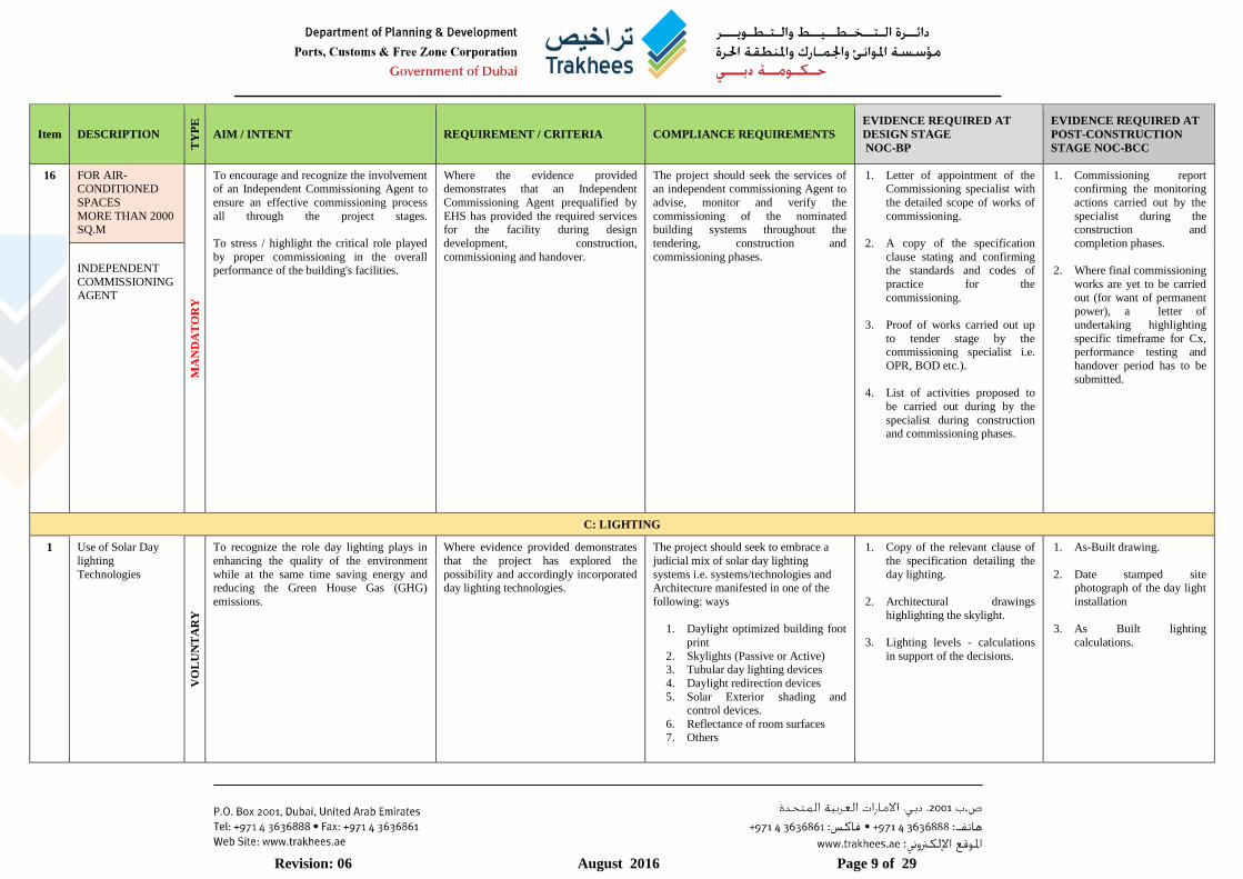
16 FOR AIR-CONDITIONED
SPACES
MORE THAN 2000 SQ.M
MA
ND
AT
OR
Y
To encourage and recognize the involvement of an Independent Commissioning Agent to
ensure an effective commissioning process
all through the project stages.
To stress / highlight the critical role played
by proper commissioning in the overall performance of the building's facilities.
Where the evidence provided demonstrates that an Independent
Commissioning Agent prequalified by
EHS has provided the required services for the facility during design
development, construction,
commissioning and handover.
The project should seek the services of an independent commissioning Agent to
advise, monitor and verify the
commissioning of the nominated building systems throughout the
tendering, construction and
commissioning phases.
1. Letter of appointment of the Commissioning specialist with
the detailed scope of works of
commissioning.
2. A copy of the specification
clause stating and confirming the standards and codes of
practice for the
commissioning.
3. Proof of works carried out up
to tender stage by the commissioning specialist i.e.
OPR, BOD etc.).
4. List of activities proposed to
be carried out during by the
specialist during construction and commissioning phases.
1. Commissioning report confirming the monitoring
actions carried out by the
specialist during the construction and
completion phases.
2. Where final commissioning
works are yet to be carried
out (for want of permanent power), a letter of
undertaking highlighting
specific timeframe for Cx, performance testing and
handover period has to be
submitted.
INDEPENDENT
COMMISSIONING AGENT
C: LIGHTING
1 Use of Solar Day
lighting
Technologies
VO
LU
NT
AR
Y
To recognize the role day lighting plays in
enhancing the quality of the environment
while at the same time saving energy and reducing the Green House Gas (GHG)
emissions.
Where evidence provided demonstrates
that the project has explored the
possibility and accordingly incorporated day lighting technologies.
The project should seek to embrace a
judicial mix of solar day lighting
systems i.e. systems/technologies and Architecture manifested in one of the
following: ways
1. Daylight optimized building foot
2. Skylights (Passive or Active) 3. Tubular day lighting devices
4. Daylight redirection devices
5. Solar Exterior shading and control devices.
6. Reflectance of room surfaces 7. Others
1. Copy of the relevant clause of
the specification detailing the
day lighting.
2. Architectural drawings
highlighting the skylight.
3. Lighting levels - calculations
in support of the decisions.
1. As-Built drawing.
2. Date stamped site photograph of the day light
installation
3. As Built lighting
calculations.

Revision: 06 August 2016 Page 10 of 29
Item DESCRIPTION
TY
PE
AIM / INTENT REQUIREMENT / CRITERIA COMPLIANCE REQUIREMENTS
EVIDENCE REQUIRED AT
DESIGN STAGE
NOC-BP
EVIDENCE REQUIRED AT
POST-CONSTRUCTION
STAGE NOC-BCC
2 Usage of energy saving high
performance lamps. M
AN
DA
TO
RY
To recognize and encourage the use of Energy efficient Lighting technology for the
lighting systems of the project in lieu of the
conventional lighting system.
Where evidence demonstrates that the development has proposed to use
Efficient lighting system.
Use of Energy efficient technologies for Lighting requirements such as
1. Compact Fluorescent Lamp (CFL)
2. Light emitting diodes (LEDs) 3. Induction lamps where relevant and
possible
The Project should adopt efficient lights
systems with dedicated fittings to
accommodate the above lamps.
1. Extract of specification necessitating energy efficient
lighting systems.
2. Design lighting drawing /
layout highlighting the lamps
and the ratings.
1. Approved material datasheets / technical
submissions.
2. As Built lighting layout
3. Date stamped site photographic evidence.
3 Usage of Electronic
Ballast
MA
ND
AT
OR
Y
To reduce energy losses from magnetic ballasts
Where evidence demonstrates that the ENTIRE development has used efficient
electronic ballasts for the lighting
systems.
All lighting ballasts should be electronic and NOT magnetic.
1. Copy of the relevant clauses of the specifications detailing
electronic ballasts.
2. Design lighting layout
highlighting electronic ballasts
in the legend section.
1. Approved material datasheets / technical
submissions for ballasts.
2. As Built lighting layout
3. Date stamped site photographic evidence.
Revision: 06 August 2016 Page 11 of 29
Item DESCRIPTION
TY
PE
AIM / INTENT REQUIREMENT / CRITERIA COMPLIANCE REQUIREMENTS
EVIDENCE REQUIRED AT
DESIGN STAGE
NOC-BP
EVIDENCE REQUIRED AT
POST-CONSTRUCTION
STAGE NOC-BCC
D: CONTROL SYSTEMS
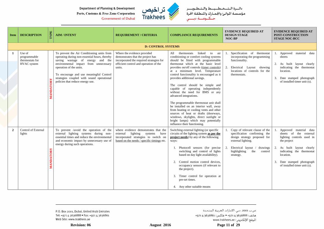
1 Use of
programmable thermostats for
HVAC system
MA
ND
AT
OR
Y
To prevent the Air Conditioning units from
operating during non-essential hours, thereby saving wastage of energy and the
environmental impact from unnecessary
operation of the units.
To encourage and use meaningful Control
strategies coupled with sound operational policies that reduce energy use.
Where the evidence provided
demonstrates that the project has incorporated the required strategies for
efficient control and operation of the
units.
All thermostats linked to air
conditioning or comfort cooling systems should be fitted with programmable
thermostat which at the basic level
provides on/off controls (timer controls) at a minimum level. Temperature
control functionality is encouraged as it
provides additional savings.
The control should be simple and
capable of operating independently without the need for BMS or any
advanced integrations.
The programmable thermostat unit shall
be installed on an interior wall, away
from heating or cooling vents and other sources of heat or drafts (doorways,
windows, skylights, direct sunlight or
bright lamps) which may potentially
influence their functioning.
1. Specification of thermostat
incorporating the programming functionality.
2. Electrical Layout showing locations of controls for the
thermostats.
1. Approved material data
sheets
2. As built layout clearly
indicating the thermostat location.
3. Date stamped photograph of installed timer unit (s).
2 Control of External lights
MA
ND
AT
OR
Y
To prevent /avoid the operation of the external lighting systems during non-
essential times and reduce the environmental
and economic impact by unnecessary use of energy during such operations.
where evidence demonstrates that the external lighting systems have
incorporated strategies to switch on
based on the needs / specific timings etc.
Switching external lighting (or specific circuits of the lighting system as per the
project needs) by any of the following
ways:
1. Photocell sensors (for precise
switching and control of lights based on day light availability).
2. Control motion control devices, occupancy sensors (if relevant to
the project).
3. Timer control for operation at
pre-set times.
4. Any other suitable means
1. Copy of relevant clause of the specification confirming the
design strategy proposed for
external lighting.
2. Electrical layout / drawings
highlighting the control strategy.
1. Approved material data sheets of the external
lighting controls used in
the project
2. As built layout clearly
indicating the thermostat location.
3. Date stamped photograph of installed timer unit (s).
Revision: 06 August 2016 Page 12 of 29
Item DESCRIPTION
TY
PE
AIM / INTENT REQUIREMENT / CRITERIA COMPLIANCE REQUIREMENTS
EVIDENCE REQUIRED AT
DESIGN STAGE
NOC-BP
EVIDENCE REQUIRED AT
POST-CONSTRUCTION
STAGE NOC-BCC
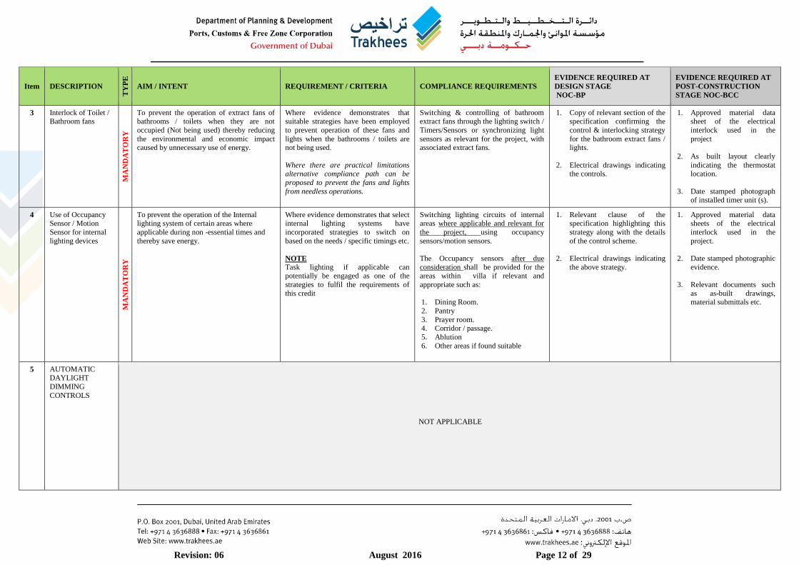
3 Interlock of Toilet / Bathroom fans
MA
ND
AT
OR
Y
To prevent the operation of extract fans of bathrooms / toilets when they are not
occupied (Not being used) thereby reducing
the environmental and economic impact caused by unnecessary use of energy.
Where evidence demonstrates that suitable strategies have been employed
to prevent operation of these fans and
lights when the bathrooms / toilets are not being used.
Where there are practical limitations alternative compliance path can be
proposed to prevent the fans and lights
from needless operations.
Switching & controlling of bathroom extract fans through the lighting switch /
Timers/Sensors or synchronizing light
sensors as relevant for the project, with associated extract fans.
1. Copy of relevant section of the specification confirming the
control & interlocking strategy
for the bathroom extract fans / lights.
2. Electrical drawings indicating the controls.
1. Approved material data sheet of the electrical
interlock used in the
project
2. As built layout clearly
indicating the thermostat location.
3. Date stamped photograph of installed timer unit (s).
4 Use of Occupancy Sensor / Motion
Sensor for internal
lighting devices
MA
ND
AT
OR
Y
To prevent the operation of the Internal lighting system of certain areas where
applicable during non -essential times and
thereby save energy.
Where evidence demonstrates that select internal lighting systems have
incorporated strategies to switch on
based on the needs / specific timings etc.
NOTE Task lighting if applicable can potentially be engaged as one of the
strategies to fulfil the requirements of
this credit
Switching lighting circuits of internal areas where applicable and relevant for
the project, using occupancy
sensors/motion sensors.
The Occupancy sensors after due
consideration shall be provided for the areas within villa if relevant and
appropriate such as:
1. Dining Room.
2. Pantry
3. Prayer room. 4. Corridor / passage.
5. Ablution
6. Other areas if found suitable
1. Relevant clause of the specification highlighting this
strategy along with the details
of the control scheme.
2. Electrical drawings indicating
the above strategy.
1. Approved material data sheets of the electrical
interlock used in the
project.
2. Date stamped photographic
evidence.
3. Relevant documents such
as as-built drawings,
material submittals etc.
5 AUTOMATIC DAYLIGHT
DIMMING
CONTROLS
NOT APPLICABLE
Revision: 06 August 2016 Page 13 of 29
Item DESCRIPTION
TY
PE
AIM / INTENT REQUIREMENT / CRITERIA COMPLIANCE REQUIREMENTS
EVIDENCE REQUIRED AT
DESIGN STAGE
NOC-BP
EVIDENCE REQUIRED AT
POST-CONSTRUCTION
STAGE NOC-BCC
E: WATER
1 Usage of Sewage Treatment Plant
(STP) for treating Grey Water and
reuse of treated
water in flushing
toilets and other
usage not involving
human direct contact.
VO
LU
NT
AR
Y
To encourage the collection and re-use of waste water to meet toilet flushing needs
and reduce the demand for potable fresh water.
Where evidence provided demonstrates the specification of systems, that
collect, store and, where necessary treat Grey water for WC and urinal flushing
purposes
The use of grey water for toilet flushing should be explored and if feasible
considered.
1. Feasibility study exploring the possibility and ruling out the
use of grey water recycling;
OR Description and specifications
of grey water recycling system.
2. Design drawings / layout
showing the treatment system.
1. Approved material data sheet of the grey water
recycling system.
2. Date stamped photographic
evidence of the installation.
3. As-built drawings of the
recycling system.
2 Performance Requirements for
Sanitary fittings
(Low Flow / Low Flush Fittings)
MA
ND
AT
OR
Y
To minimize the consumption of potable water in sanitary applications by
encouraging the use of low water use fittings
Where evidence provided demonstrates that the specification includes taps,
urinals, WCs and showers that consume
less potable water in use than standard specifications for the same type of
fittings.
The FLOW and FLUSH fixtures used in the project should conform to the flow
rates specified in the Table-5 of the
Annexure.
1. Relevant extract of the specification detailing the
sanitary fittings.
2. Plumbing drawings
highlighting the flow / flush
rates of the fixtures.
1. Approved material data sheet of flow / flush
fixtures installed.
2. Date stamped photographic
evidence of the fixtures.
3 Water efficient
landscaping and
irrigation systems
Drip irrigation methods for
vegetation according
to climate and seasonal conditions.
MA
ND
AT
OR
Y
To reduce the consumption of potable water
for ornamental planting and landscape
irrigation in the development.
Where evidence provided demonstrates
that a low-water irrigation
strategy/system has been installed.
All irrigation should be delivered by
drip irrigation systems together with
other strategies such as moisture sensors, landscape zoning, timers,
controllers and self-closing nozzles.
For those Villa developments where
irrigation is proposed with sprinklers, a combination of high efficiency sprinkler
with timer switch controls should be
utilized.
Use of native plants is encouraged
1. Marked-up site plan showing
all landscaped areas to be
irrigated.
2. Specifications of irrigation systems to be installed.
3. Details of the Native plants proposed to be used.
1. Approved material data
sheet of the irrigation
equipment.
2. As-built landscaping drawing.
Revision: 06 August 2016 Page 14 of 29
Item DESCRIPTION
TY
PE
AIM / INTENT REQUIREMENT / CRITERIA COMPLIANCE REQUIREMENTS
EVIDENCE REQUIRED AT
DESIGN STAGE
NOC-BP
EVIDENCE REQUIRED AT
POST-CONSTRUCTION
STAGE NOC-BCC
4 Water efficient landscaping and
irrigation systems
Eliminate potable
water use or
irrigation
VO
LU
NT
AR
Y
To eliminate the consumption of potable water for ornamental planting and landscape
irrigation
Where evidence provided demonstrates that no potable water is being used for
irrigation or the irrigation has been
totally eliminated
The following demonstrates compliance:
The irrigation system specified for
internal or external planting and/or landscaping uses ONLY the following:
a) Captured Rain water b) Recycled waste water
c) Non potable water treated by a public
agency d) The only planting specified is
restricted to species that thrive in hot
and dry conditions. e)The system uses reclaimed condensate
water from air conditioning systems
f) combination of the above
Where a sub-surface drip feed irrigation
system or a system using reclaimed condensate water is installed for
external areas, a facility or mechanism
to prevent the irrigation system from
activating during the day must be
present
1. Relevant clause of specification on the irrigation
strategy.
2. Proposed site plan, marked
up to illustrate the scope of
the irrigation specified including controls..
1. Approved material data sheet of the irrigation
system components where
relevant.
2. Date stamped photographic
evidence of the installation
3. As-built drawings of the
landscaping and irrigation system.
F: ENVIRONMENT & INTERNAL AIR QUALITY
1 Building internal ventilation and
Minimum Indoor
Air Quality (IAQ)
MA
ND
AT
OR
Y
To recognize the provision of adequate fresh air rates by establishing minimum IAQ
performance in order to maintain a healthy
indoor environment, thus contributing to the comfort and well-being of the occupants.
This also includes Pantry/ Kitchen, and stores besides the office areas.
Where evidence provided demonstrates that each space within the development
achieves recommended minimum fresh
air rates as stated in the regulation
Meet the minimum requirement of ASHRAE 62.2-2007, Ventilation for
acceptable indoor air quality (IAQ) and
design ventilation systems to meet /exceed the rates.
Ventilation / Fresh Air requirements for the conditioned space, bathrooms and
kitchens should comply with the Air
quantities mentioned in Table-7 of the Annexure.
Naturally Ventilated buildings shall comply with ASHRAE 62.1 2007
STANDARDS.
1. A copy of the relevant clauses of specification on the
ventilation system.
2. Fresh air calculations in the
tabular form for all the areas.
3. Schedule of the ventilation air
quantity along with the flow
rate of ventilation being provided.
4. Where energy recovery wheel is used, the total fresh air
quantity should bear relevance to the sizing of ERV.
1. Approved material data sheet of the fresh air fans /
systems.
2. Date stamped
photographic evidence of
the installation
3. As-built drawings of the
fresh air system.
Revision: 06 August 2016 Page 15 of 29
Item DESCRIPTION
TY
PE
AIM / INTENT REQUIREMENT / CRITERIA COMPLIANCE REQUIREMENTS
EVIDENCE REQUIRED AT
DESIGN STAGE
NOC-BP
EVIDENCE REQUIRED AT
POST-CONSTRUCTION
STAGE NOC-BCC
2 Control of Environmental
Tobacco Smoke
NOT APPLICABLE
3 Low Emitting
Paints, Coatings,
Adhesives and Sealants
MA
ND
AT
OR
Y
To recognize and encourage a healthy
internal environment through the
specification of internal finishes and fittings with low emissions of volatile organic
compounds (VOCs).
Reduce the quantity of indoor air
contaminants that are odorous, irritating
and/or harmful to the comfort and well-being of the installers and occupants.
Where evidence provided demonstrates
that the emissions of VOCs and other
substances from key internal finishes and fittings comply with best practice
and internationally accepted levels.
All adhesives and sealants used on the
interior of the building (defined as
inside of the weatherproofing system and applied on-site) must comply with
the requirements as mentioned in the
Table-6 of the Annexure that has been aligned to LEED Reference Guide.
All paints and coatings used in the project shall have Volatile organic
compounds (VOCs) that are within the
limits as prescribed in the Table-6 of the Annexure, which has been aligned to
LEED Reference Guide.
A copy of the relevant
specification clause confirming that
the VOC content of the relevant specified product types will
comply with the standards specified
above.
1. Provide list of each indoor
adhesive sealant, primer
product, aerosol adhesive and indoor paint and coating
including manufacturer,
product name, VOC data and corresponding allowable
VOC from the reference
standard.
2. Copy of the manufacturer's
literature / approval sheets.
3. Date stamped photographic
evidence.
4 Usage of Ozone
friendly materials in
Air Conditioning
equipment, thermal insulation, foam &
fire fighting
equipment.
MA
ND
AT
OR
Y
To reduce the potential for long-term
damage to the Earth’s stratospheric ozone
layer through the accidental release of ozone
depleting substances to the atmosphere
Where all refrigerant types in use have
an ozone depletion potential (ODP) of
ZERO or where there are no refrigerants
present.
CFCs should NOT be used in the
project
HVAC and Refrigeration systems should use Non-CFC refrigerants and
must have Zero Ozone Depleting
Potential (ODP).
Use of R22 is discouraged.
All thermal insulation and fire
suppressants should have zero Ozone Depleting Potential (ODP) substances.
1. Specifications showing the
substances used for each of
these items and supporting
technical documentation confirming zero ODP.
1. Approved material
datasheet
2. Date stamped photographic evidence of the units where
applicable along with the
name plates of installed units
Revision: 06 August 2016 Page 16 of 29
Item DESCRIPTION
TY
PE
AIM / INTENT REQUIREMENT / CRITERIA COMPLIANCE REQUIREMENTS
EVIDENCE REQUIRED AT
DESIGN STAGE
NOC-BP
EVIDENCE REQUIRED AT
POST-CONSTRUCTION
STAGE NOC-BCC
G: Sustainable Site & Management
1 Sustainable Site and
Management
MA
ND
AT
OR
Y
Reduce pollution from construction site by
controlling air borne dust generation, soil erosion, etc.
Where the Evidence provided
demonstrates that an elaborate construction Erosion / sedimentation
control plan is put in place by the
contractor in line with the Best practice policies in respect of
a) Air (dust) pollution arising from the site.
b) Water (ground and surface) pollution
occurring on site.
Provide erosion and sedimentation
control plan to prevent 1) Loss of soil
2) Prevent air pollution from dust
3) Prevent sedimentation of storm sewer
1. Submission of Erosion and
sedimentation control plan required as part of the
specification.
2. Copies of drawings to
document erosion /
sedimentation control plan.
1. Proof of training on ESC
implementation
2. Date stamped photos of
ESC implementation.
2 Heat Island Effect
Non-Roof
MA
ND
AT
OR
Y
Reduce heat islands to minimize impact on
micro climate and human and wildlife inhabitants.
Where the evidence provided
demonstrates that the design incorporates technology and materials to
reduce the heat island effect brought
from NON-ROOF COMPONENTS
The Site hardscape comprising the
paving and parking sheds should incorporate one or more of the following
strategies:
1) Paving materials with Solar Reflective index (SRI) of minimum 29.
2) Open Grid Paving system with 50%
perviousness and /Or SRI of minimum
29
3) Parking spaces under cover with SRI
of 29
OPEN Grid Pavers for Non-Traffic
areas are encouraged.
1. Specification of the materials,
SRI etc.
2. Drawings of the site plan
identifying the site hardscape elements.
1. Approved material data
sheet of the Non roof components
2. Date stamped photograph of the installation.
3. As-built drawings / layout
clearly highlighting the SRI
value of the non-roof
components
3 Heat Island Effect
Roof (Use of light
and heat reflective colours on roofs)
MA
ND
AT
OR
Y
Reduce heat islands to minimize impact on
micro climate and human and wildlife
inhabitants.
Where the evidence provided
demonstrates that the design
incorporates technology and materials to reduce the heat island effect brought
from ROOF COMPONENTS
Use roofing materials with SRI as
mentioned under for minimum 75% of
the roof area:
a) Low slope 78
b) High slope 29
1. Specification of the materials,
SRI etc.
2. Drawings of the site plan
identifying the site hardscape
elements.
3. Elevation showing roof angle
1. Approved material data
sheet of the roof
components
2. Date stamped photograph
of the installation.
3. As-built drawings / layout
clearly highlighting the SRI value of the roof
components
4.
Revision: 06 August 2016 Page 17 of 29
Item DESCRIPTION
TY
PE
AIM / INTENT REQUIREMENT / CRITERIA COMPLIANCE REQUIREMENTS
EVIDENCE REQUIRED AT
DESIGN STAGE
NOC-BP
EVIDENCE REQUIRED AT
POST-CONSTRUCTION
STAGE NOC-BCC
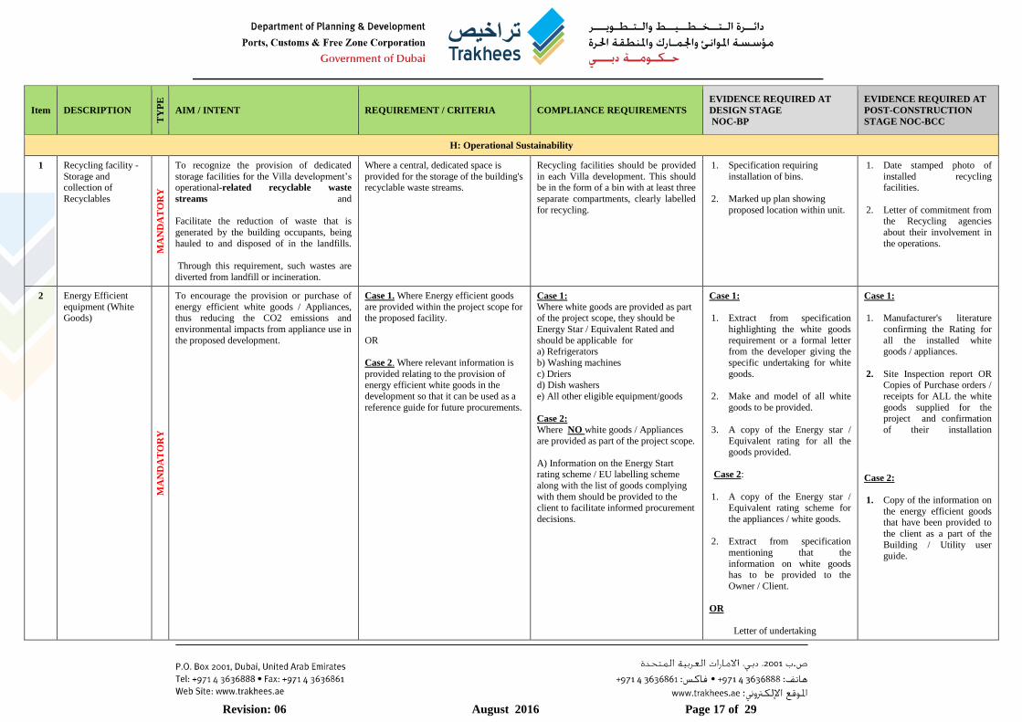
H: Operational Sustainability
1 Recycling facility -
Storage and collection of
Recyclables
MA
ND
AT
OR
Y
To recognize the provision of dedicated
storage facilities for the Villa development’s operational-related recyclable waste
streams and
Facilitate the reduction of waste that is
generated by the building occupants, being
hauled to and disposed of in the landfills.
Through this requirement, such wastes are
diverted from landfill or incineration.
Where a central, dedicated space is
provided for the storage of the building's recyclable waste streams.
Recycling facilities should be provided
in each Villa development. This should be in the form of a bin with at least three
separate compartments, clearly labelled
for recycling.
1. Specification requiring
installation of bins.
2. Marked up plan showing
proposed location within unit.
1. Date stamped photo of
installed recycling facilities.
2. Letter of commitment from the Recycling agencies
about their involvement in
the operations.
2 Energy Efficient
equipment (White Goods)
MA
ND
AT
OR
Y
To encourage the provision or purchase of
energy efficient white goods / Appliances, thus reducing the CO2 emissions and
environmental impacts from appliance use in
the proposed development.
Case 1. Where Energy efficient goods
are provided within the project scope for the proposed facility.
OR
Case 2. Where relevant information is
provided relating to the provision of
energy efficient white goods in the
development so that it can be used as a
reference guide for future procurements.
Case 1:
Where white goods are provided as part of the project scope, they should be
Energy Star / Equivalent Rated and
should be applicable for a) Refrigerators
b) Washing machines
c) Driers
d) Dish washers
e) All other eligible equipment/goods
Case 2: Where NO white goods / Appliances
are provided as part of the project scope.
A) Information on the Energy Start rating scheme / EU labelling scheme
along with the list of goods complying
with them should be provided to the client to facilitate informed procurement
decisions.
Case 1: 1. Extract from specification
highlighting the white goods
requirement or a formal letter from the developer giving the
specific undertaking for white
goods.
2. Make and model of all white
goods to be provided.
3. A copy of the Energy star /
Equivalent rating for all the goods provided.
Case 2:
1. A copy of the Energy star / Equivalent rating scheme for
the appliances / white goods.
2. Extract from specification
mentioning that the
information on white goods has to be provided to the
Owner / Client.
OR
Letter of undertaking
Case 1:
1. Manufacturer's literature
confirming the Rating for
all the installed white goods / appliances.
2. Site Inspection report OR
Copies of Purchase orders /
receipts for ALL the white
goods supplied for the project and confirmation
of their installation
Case 2:
1. Copy of the information on
the energy efficient goods that have been provided to
the client as a part of the
Building / Utility user guide.
Revision: 06 August 2016 Page 18 of 29
Item DESCRIPTION
TY
PE
AIM / INTENT REQUIREMENT / CRITERIA COMPLIANCE REQUIREMENTS
EVIDENCE REQUIRED AT
DESIGN STAGE
NOC-BP
EVIDENCE REQUIRED AT
POST-CONSTRUCTION
STAGE NOC-BCC
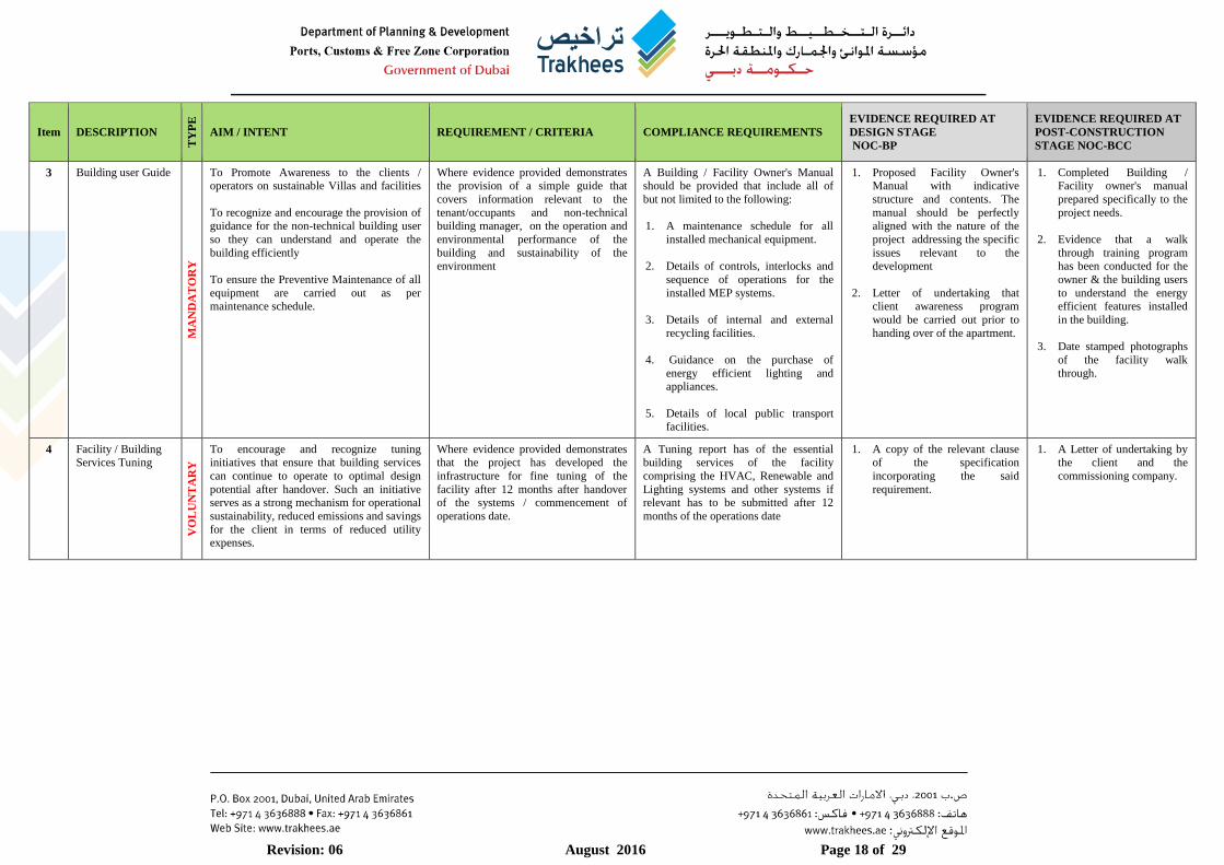
3 Building user Guide
MA
ND
AT
OR
Y
To Promote Awareness to the clients / operators on sustainable Villas and facilities
To recognize and encourage the provision of guidance for the non-technical building user
so they can understand and operate the
building efficiently
To ensure the Preventive Maintenance of all
equipment are carried out as per maintenance schedule.
Where evidence provided demonstrates the provision of a simple guide that
covers information relevant to the
tenant/occupants and non-technical building manager, on the operation and
environmental performance of the
building and sustainability of the environment
A Building / Facility Owner's Manual should be provided that include all of
but not limited to the following:
1. A maintenance schedule for all
installed mechanical equipment.
2. Details of controls, interlocks and
sequence of operations for the
installed MEP systems.
3. Details of internal and external
recycling facilities.
4. Guidance on the purchase of
energy efficient lighting and appliances.
5. Details of local public transport facilities.
1. Proposed Facility Owner's Manual with indicative
structure and contents. The
manual should be perfectly aligned with the nature of the
project addressing the specific
issues relevant to the development
2. Letter of undertaking that client awareness program
would be carried out prior to
handing over of the apartment.
1. Completed Building / Facility owner's manual
prepared specifically to the
project needs.
2. Evidence that a walk
through training program has been conducted for the
owner & the building users
to understand the energy efficient features installed
in the building.
3. Date stamped photographs
of the facility walk
through.
4 Facility / Building
Services Tuning
VO
LU
NT
AR
Y
To encourage and recognize tuning
initiatives that ensure that building services
can continue to operate to optimal design
potential after handover. Such an initiative serves as a strong mechanism for operational
sustainability, reduced emissions and savings
for the client in terms of reduced utility expenses.
Where evidence provided demonstrates
that the project has developed the
infrastructure for fine tuning of the
facility after 12 months after handover of the systems / commencement of
operations date.
A Tuning report has of the essential
building services of the facility
comprising the HVAC, Renewable and
Lighting systems and other systems if relevant has to be submitted after 12
months of the operations date
1. A copy of the relevant clause
of the specification
incorporating the said
requirement.
1. A Letter of undertaking by
the client and the
commissioning company.
Revision: 06 August 2016 Page 19 of 29
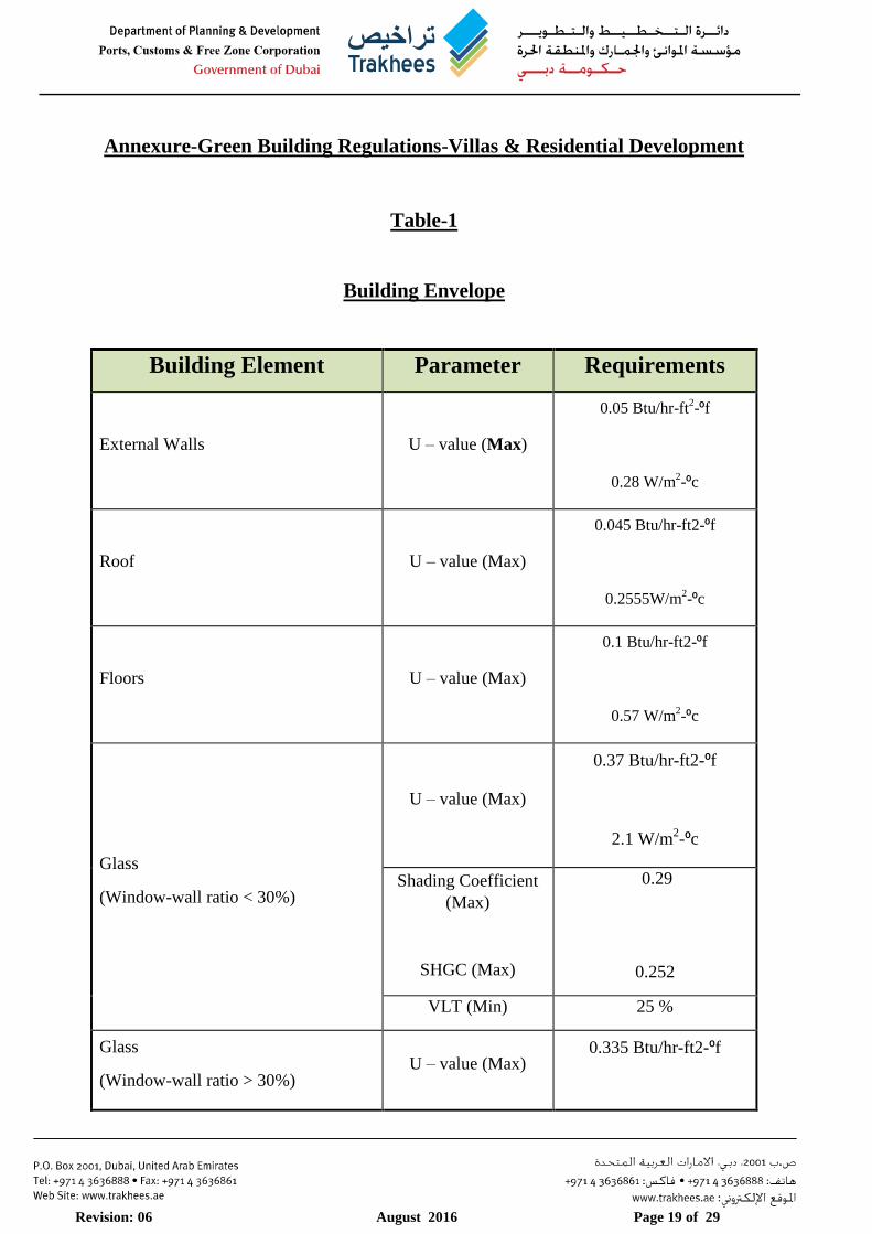
Annexure-Green Building Regulations-Villas & Residential Development
Table-1
Building Envelope
Building Element Parameter Requirements
External Walls U – value (Max)
0.05 Btu/hr-ft2-⁰f
0.28 W/m2-⁰c
Roof U – value (Max)
0.045 Btu/hr-ft2-⁰f
0.2555W/m2-⁰c
Floors U – value (Max)
0.1 Btu/hr-ft2-⁰f
0.57 W/m2-⁰c
Glass
(Window-wall ratio < 30%)
U – value (Max)
0.37 Btu/hr-ft2-⁰f
2.1 W/m2-⁰c
Shading Coefficient
(Max)
SHGC (Max)
0.29
0.252
VLT (Min) 25 %
Glass
(Window-wall ratio > 30%) U – value (Max)
0.335 Btu/hr-ft2-⁰f
Revision: 06 August 2016 Page 20 of 29
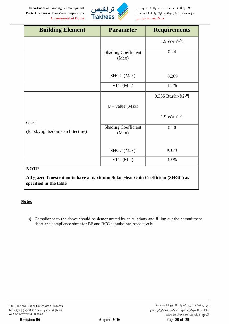
Building Element Parameter Requirements
1.9 W/m2-⁰c
Shading Coefficient
(Max)
SHGC (Max)
0.24
0.209
VLT (Min) 11 %
Glass
(for skylights/dome architecture)
U – value (Max)
0.335 Btu/hr-ft2-⁰f
1.9 W/m2-⁰c
Shading Coefficient
(Max)
SHGC (Max)
0.20
0.174
VLT (Min) 40 %
NOTE
All glazed fenestration to have a maximum Solar Heat Gain Coefficient (SHGC) as
specified in the table
Notes
a) Compliance to the above should be demonstrated by calculations and filling out the commitment
sheet and compliance sheet for BP and BCC submissions respectively

Revision: 06 August 2016 Page 21 of 29
Table-2
Air Tightness / Envelope Tightness Guidelines
INFRARED THERMOGRAPHY
Eligibility Requirements of Thermographers
1. The thermographer should be suitably qualified / trained / certified – Level 1
2. Affiliated to ATTMA / BINDT
3. Minimum 2 years of demonstrable experience
4. The testing technician should be competent enough to do the test according to the proper
procedure and should be able to locate any leakages as well
5. The technician should be equipped with sensitive and calibrated equipment to test the building
according to the procedure
CV should be submitted to Trakhees-EHS for review and approval
Test Conditions
The conditions (measurement circumstances) should follow the protocol of the referenced standard and
should further ensure the following requirements are fulfilled
1. Atmospheric circumstances and the temperature difference
2. Wind speed and direction relative to the building.
3. An evenly distributed pressure across the area
Reporting
The report should be comprehensive and of good quality that helps the professionals to make use of the
information for proper corrective measures. It should follow the protocols of the standards and as a minimum
comprise the following
1. Background to the objective and principles of the test
2. Location, orientation, date and time of survey
3. Brief description of the construction of the building based on drawings or other available
documentation
4. Type(s) of surface material(s) used in the structure and the estimated value(s) of emissivity of this
(these) materials(s).
5. A unique identifying reference
6. Thermographer’s name, affiliation and qualifications
7. Type of construction
8. Weather conditions, wind speed and direction, last precipitation, sunshine, degree of cloud cover.
9. Ambient temperatures inside and outside before, at the beginning of the survey and the time of each

Revision: 06 August 2016 Page 22 of 29
image. Air temperature and radiant temperature should be recorded
10. Inside air temperature and air temperature difference across the envelope during the examination
11. Inside Relative Humidity data and outside Relative Humidity data for the duration of the test
12. Precipitation, direction of the wind, and velocity of the wind during the examination.
13. Statement of any deviation from relevant test requirements
14. Sketches and / or photographs of the building showing the positions of the thermographs
15. Specification of the equipment used, including make, model and serial number , last calibration date,
any known defects.
16. Thermographs indicating temperature levels obtained from the test, showing parts of the building
where thermal anomalies have been detected, with indications of their respective positions, and the
position of the IR camera with respect to the measurement target, and with comments on the
appearance of the thermal images, if possible with reference to parts of the building envelope with
acceptable performance
17. Date and signature and professional seal
18. Type, extent and position of each observed defect
19. Results of any supplementary measurements and investigations
BLOWER DOOR TESTING
Eligibility Requirements of testing company
1. A blower door testing training certificate provided by an ATTMA /BINDT Certified testing organization
of suitable Level required for undertaking the tests
2. Minimum 2 years of demonstrable experience
The testing technician should be competent enough to do the test according to the proper
procedure and should be able to locate any leakages as well. CV should be submitted to Trakhees-
EHS for review and approval
3. The technician should be equipped with sensitive and calibrated equipment to test the building
according to the procedure
Test Conditions
1. The ambient atmospheric conditions (measurement circumstances) should be measured before and
after the tests and should follow the CIBSE TM23 - “Testing of buildings for air leakage" protocol and
the referenced standard. Measurements taken for following are to be within acceptable limits as
described in the CIBSE TM23 guidelines
a. Temperature
b. Humidity
c. Wind speed
d. Barometric pressure
2. 2 Bias pressure readings to be taken before and after test and averaged as described in the CIBSE
TM23 guidelines
Reporting
The report should be comprehensive and of good quality that helps the professionals to make use of the
information for proper corrective measures. It should follow the protocols of the standards and as a minimum

Revision: 06 August 2016 Page 23 of 29
comprise the following
1. Background to the objective and principles of the test
2. Location, orientation, date and time of the test
3. Brief description of the construction of the building based on drawings or other available
documentation
4. Description of the activities, measurement conditions and if applicable any notes about closed or
opened doors etc.
5. Presentation of the measurement-results as well as any digital (visual) images of the object
6. In case the building doesn’t pass the test: evidence of leakage provided with the use of visual or
thermal images.
7. Conclusions and recommendations

Revision: 06 August 2016 Page 24 of 29
Table-3
Minimum HVAC system performance criteria (EER)
SPLIT AND PACKAGED UNITS
Synod Capacities EER (Minimum)
1 Less than 2.5TR 11.8
2 Less than 5.4 TR 11.8
3 ≥ 5.4 TR and < 11.4 TR 11.5
4 ≥ 11.4 TR and < 19.8 TR 11.3
5 ≥ 19.8 TR and < 63.4 TR 10.5
6 ≥ 63.4 TR 10.0
CASSETTE TYPE UNITS EER ≥ 11.5
Notes
1. The above table stipulates the minimum HVAC energy efficiency requirement (system
performance and has taken into consideration the minimum requirements of ASHRAE 90.1
stipulated vide its Table 6.8.1A and the high energy optimization needs of the jurisdiction.
This also reiterates that under no circumstances would the EER be less that the ASHRAE
stipulated values.
2. It is a well-known fact that HVAC systems consume up to 75% of the building energy
consumption especially during summer. These basic EER requirements in conjunction with
integrated design principles and other adequate green measures taken during design and
construction stages of the project would greatly enhance the operational sustainability of the
facility through efficient performance of the HVAC systems.
Revision: 06 August 2016 Page 25 of 29
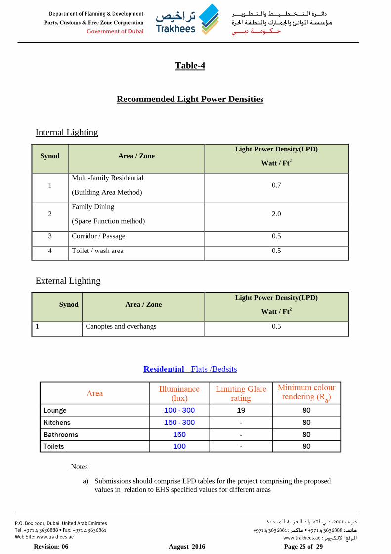
Table-4
Recommended Light Power Densities
Internal Lighting
Synod Area / Zone Light Power Density(LPD)
Watt / Ft2
1 Multi-family Residential
(Building Area Method) 0.7
2 Family Dining
(Space Function method) 2.0
3 Corridor / Passage 0.5
4 Toilet / wash area 0.5
External Lighting
Synod Area / Zone Light Power Density(LPD)
Watt / Ft2
1 Canopies and overhangs 0.5
Notes
a) Submissions should comprise LPD tables for the project comprising the proposed
values in relation to EHS specified values for different areas

Revision: 06 August 2016 Page 26 of 29
Table-5
Minimum performance criteria for sanitary wares
Fixture Type Requirements REMARKS
Water Closets 3/6 l/flush
Dual flush type
Urinals
2.0 l/flush
or
waterless
Sensor based urinal
systems are also
acceptable.
Wash Basin Mixture/
Faucets / Sink Mixer / Bath Mixer 6.0 l/min.
At 413.7 Kpa reference
pressure
Hand Showers 8.0 l/min. At 551.6 Kpa reference
pressure
½’Water Tap 6.0 ~ 9.0 l/min. At 413.7 Kpa reference
pressure
½’Shattaf None
Notes
1. The table provides an outline / guidance on the flow and flush fixture requirements to be used in
the project. This however does not stop a project from seeking higher efficiencies.
2. It should be ensured that laundry equipment , dish washers etc. that have not been mentioned in
the above table are selected from energy star / equivalent accredited products for achieving
maximum water savings
Revision: 06 August 2016 Page 27 of 29
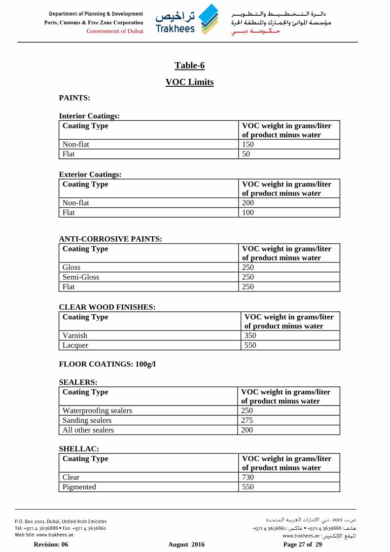
Table-6
VOC Limits
PAINTS:
Interior Coatings:
Coating Type VOC weight in grams/liter
of product minus water
Non-flat 150
Flat 50
Exterior Coatings:
Coating Type VOC weight in grams/liter
of product minus water
Non-flat 200
Flat 100
ANTI-CORROSIVE PAINTS:
Coating Type VOC weight in grams/liter
of product minus water
Gloss 250
Semi-Gloss 250
Flat 250
CLEAR WOOD FINISHES:
Coating Type VOC weight in grams/liter
of product minus water
Varnish 350
Lacquer 550
FLOOR COATINGS: 100g/l
SEALERS:
Coating Type VOC weight in grams/liter
of product minus water
Waterproofing sealers 250
Sanding sealers 275
All other sealers 200
SHELLAC:
Coating Type VOC weight in grams/liter
of product minus water
Clear 730
Pigmented 550
Revision: 06 August 2016 Page 28 of 29
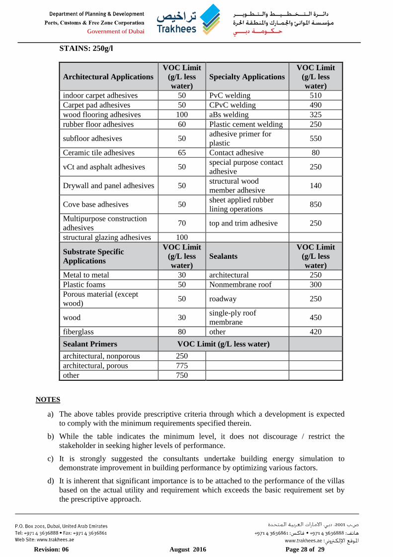
STAINS: 250g/l
Architectural Applications
VOC Limit
(g/L less
water)
Specialty Applications
VOC Limit
(g/L less
water)
indoor carpet adhesives 50 PvC welding 510
Carpet pad adhesives 50 CPvC welding 490
wood flooring adhesives 100 aBs welding 325
rubber floor adhesives 60 Plastic cement welding 250
subfloor adhesives 50 adhesive primer for
plastic 550
Ceramic tile adhesives 65 Contact adhesive 80
vCt and asphalt adhesives 50 special purpose contact
adhesive 250
Drywall and panel adhesives 50 structural wood
member adhesive 140
Cove base adhesives 50 sheet applied rubber
lining operations 850
Multipurpose construction
adhesives 70 top and trim adhesive 250
structural glazing adhesives 100
Substrate Specific
Applications
VOC Limit
(g/L less
water)
Sealants
VOC Limit
(g/L less
water)
Metal to metal 30 architectural 250
Plastic foams 50 Nonmembrane roof 300
Porous material (except
wood) 50 roadway 250
wood 30 single-ply roof
membrane 450
fiberglass 80 other 420
Sealant Primers VOC Limit (g/L less water)
architectural, nonporous 250
architectural, porous 775
other 750
NOTES
a) The above tables provide prescriptive criteria through which a development is expected
to comply with the minimum requirements specified therein.
b) While the table indicates the minimum level, it does not discourage / restrict the
stakeholder in seeking higher levels of performance.
c) It is strongly suggested the consultants undertake building energy simulation to
demonstrate improvement in building performance by optimizing various factors.
d) It is inherent that significant importance is to be attached to the performance of the villas
based on the actual utility and requirement which exceeds the basic requirement set by
the prescriptive approach.
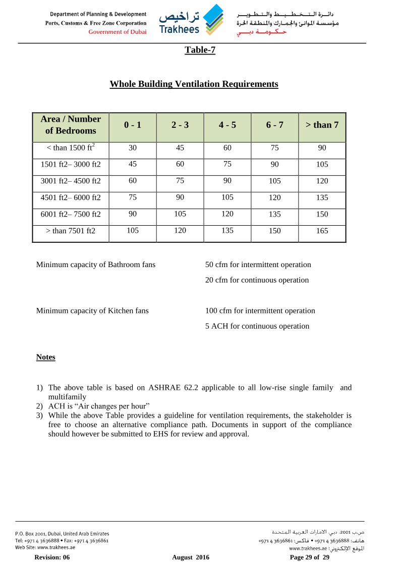
Revision: 06 August 2016 Page 29 of 29
Table-7
Whole Building Ventilation Requirements
Area / Number
of Bedrooms 0 - 1 2 - 3 4 - 5 6 - 7 > than 7
< than 1500 ft2 30 45 60 75 90
1501 ft2– 3000 ft2 45 60 75 90 105
3001 ft2– 4500 ft2 60 75 90 105 120
4501 ft2– 6000 ft2 75 90 105 120 135
6001 ft2– 7500 ft2 90 105 120 135 150
> than 7501 ft2 105 120 135 150 165
Minimum capacity of Bathroom fans 50 cfm for intermittent operation
20 cfm for continuous operation
Minimum capacity of Kitchen fans 100 cfm for intermittent operation
5 ACH for continuous operation
Notes
1) The above table is based on ASHRAE 62.2 applicable to all low-rise single family and
multifamily
2) ACH is “Air changes per hour”
3) While the above Table provides a guideline for ventilation requirements, the stakeholder is
free to choose an alternative compliance path. Documents in support of the compliance
should however be submitted to EHS for review and approval.