Trainz TC3 Signalling Tutorial - Trainz Classics Uk · Trainz TC3 Signalling Tutorial Trainz...
15
Trainz TC3 Signalling Tutorial Trainz signals can now be placed to replicate the block working that operated widely about 1960 which is the period depicted in TC3. This does not replace the signalling systems that were supported in Trs2006 but is an additional feature. Consequently this tutorial addresses itself solely to signalling applied to block working. 1. Introduction to Block Working In the block system of signalling a railway route is divided into block sections separated from each other by signal boxes and signals. The general principle is that no train leaves the protection of the signals of one box, to enter a block section, until the preceding train has cleared the signals of the next box. In other words there is at least one complete block section between any two moving engines or trains on the same line of rails. 2. Description of Semaphore Signals for Block Working The signals which control the movement of trains are known as ‘fixed’ signals because of their fixed location. In the 1960s most signals of this type in the UK were still semaphore of which there are two principal types: Figure 1 “Stop” signals which have square ended arms painted red on the face, with a vertical white stripe near the outer end. At night the stop signal displays a red light for stop and green for clear. Figure 2 “Distant” signals with a fishtail type notch in the end of the arm. This signal type is painted yellow with a forked black stripe near the outer end. At night a distant signal displays a yellow light for caution and green for clear. In all countries where traffic follows the left hand track the signal arms, as seen by the driver point to the left of the post. Where rail traffic follows the right hand track all signal arms point to the right. In the stop or ‘on’ mode (caution in the case of a distant signal) the signal arm is horizontal but to show go (or more commonly ‘clear’ or ‘off’) the end is raised or lowered to 45 degrees or more.
Transcript of Trainz TC3 Signalling Tutorial - Trainz Classics Uk · Trainz TC3 Signalling Tutorial Trainz...

Trainz TC3 Signalling Tutorial Trainz signals can now be placed to replicate the block working that operated widely about 1960 which is the period depicted in TC3. This does not replace the signalling systems that were supported in Trs2006 but is an additional feature. Consequently this tutorial addresses itself solely to signalling applied to block working. 1. Introduction to Block Working In the block system of signalling a railway route is divided into block sections separated from each other by signal boxes and signals. The general principle is that no train leaves the protection of the signals of one box, to enter a block section, until the preceding train has cleared the signals of the next box. In other words there is at least one complete block section between any two moving engines or trains on the same line of rails. 2. Description of Semaphore Signals for Block Working The signals which control the movement of trains are known as ‘fixed’ signals because of their fixed location. In the 1960s most signals of this type in the UK were still semaphore of which there are two principal types:
Figure 1
“Stop” signals which have square ended arms painted red on the face, with a vertical white stripe near the outer end. At night the stop signal displays a red light for stop and green for clear.
Figure 2
“Distant” signals with a fishtail type notch in the end of the arm. This signal type is painted yellow with a forked black stripe near the outer end. At night a distant signal displays a yellow light for caution and green for clear.
In all countries where traffic follows the left hand track the signal arms, as seen by the driver point to the left of the post. Where rail traffic follows the right hand track all signal arms point to the right. In the stop or ‘on’ mode (caution in the case of a distant signal) the signal arm is horizontal but to show go (or more commonly ‘clear’ or ‘off’) the end is raised or lowered to 45 degrees or more.

3. Block working in practice As a train approaches a signal box, the first signal reached is the distant signal. When the distant arm is ‘on’ it is warning the driver that the next signal is at danger. The driver can pass the distant signal but must be ready to bring the train to a stand before the stop signal. The distance between the distant and stop signal varies from several hundred yards to a mile according to the speed limit and gradient. If the distant is in the clear position the driver knows that all stop signals controlling access to the next block section are also clear, and therefore the train can proceed without slackening pace. This is because the signalman is unable to pull off the distant until all stop signals are also off. The signal box controls at least one, normally two and often three or more stop signals in each direction. The home signal is normally the first, and sometimes the only stop signal reached by a passing train. The second stop signal is the starter, and it usually guards the exit to the next block section. If there are sidings beyond the starter an “advanced starter” is provided, so that a train may carry out shunting duties within the protection of the signals controlled by the signal box.
Figure 3
If a signal box is guarding a junction it is normal practice for the home signals for the two converging routes to be placed before the junction. These maybe preceded by “outer homes” on one or both routes. This allows the acceptance of trains from the box(es) in the rear, even though the junction maybe blocked, the train is permitted to draw up to the outer home as there are two stop signals, the outer home and the home standing between the train and any possible obstruction.
Figure 4
The length of a block section is generally determined by the traffic density of the route, the busier the route the shorter the block section. The busy WCML in the UK had signal boxes placed at intervals of about 2 miles, whilst block sections of up to 10 miles were found in the more remote areas of Scotland. Another factor is that signal boxes have to be close to junctions when there are no point motors to assist the signalman. Consequently at large stations there are quite often signal boxes placed within a few hundred yards of each other, resulting in very short block sections.

With short block sections the starting signal of one box is often on the same post as the distant of the box in front. This is called a combination signal and even though each signal is under the control of different signal boxes only certain displays are allowed. For example the distant signal of a combination cannot display “clear” when the stop signal is at danger.
Figure 5
At junctions, signals are grouped to give the clearest possible indication of the purpose served by each. Where lines diverge the highest arm of a group of signals refers to the main line; arms at lower levels to the left and/ or right indicate divergences in those directions. 4. Communication between Signal Boxes
To effectively administer the block system and to allow trains to proceed from section to section without delay a strict protocol of communication was followed by signalmen. Above the familiar row of levers in a signal box stands the instrument shelf with the block instruments on it. On the front of each instrument is a dial with a lever or slide indicating three settings: “Line Clear”, “Line Blocked” (or “Normal”) or “Train on Line”. This instrument is connected and paired electrically with a corresponding one in the next box, giving identical indications. Under the instrument is a handle which enables the signalman to adjust the needle or slide as required. There is also a plunger which operates a single stroke bell in the next box. A similar pair of instruments, but this one visual only because the needle or slide is operated from the other box, provides for the running of trains in the opposite direction. There are two further instruments, again one operable and the other visual only, to maintain communication with the next box in the other direction.
Let us suppose we are in the middle box, B of three boxes, A, B and C, and that a train is expected in the A-C direction. The Block Instrument positions and the signal aspects are Illustrated in Fig 6.
Figure 6

For B, the first indication of its approach is a single beat on the A-B bell, rung by signalman A; this is the ”Call attention” signal, which B acknowledges, in A’s box, by a single beat on the B-A bell circuit. Next, A rings a code enquiry which asks “is line clear for a train?” The code varies according to the type of train that is being offered forward. Provided the line is clear, B acknowledges this by repeating the code back to A. At the same time B sets the needles of his and A’s A-B instruments to “Line Clear”. The train has been accepted by B and A is now permitted to pull his signals off to allow passage into the A-B block section. B must not now permit any train or engine movement that will foul or block the line on which the train will run. The changed Block Instrument positions and the signal aspects are illustrated in Fig 7.
Figure 7
As the train passes box A, the signalman rings two beats to B, which indicates “train on line” or “train entering section”. After the repetitive acknowledgement of this on the bell B sets the needles of his and A’s A-B instrument to “Train on Line”. B then requests ‘Is line clear?” from C using the same code to describe the train as had been used by A. After watching the needle of the B-C instrument, operated by C, move to “Line Clear” B will then pull off his signals. If the distance from A to B is fairly short B will have already obtained line clearance from C before the train has passed signalbox A. This is to allow B time to pull off his signals before the train approaches his signals. The new Block Instrument positions and the signal aspects are illustrated in Fig 8.
Figure 8
As the train passes signalbox B he rings “train entering section” to C and having received the bell acknowledgement and seen the needle of the B-C instrument move to “Train on Line” he puts his signals back to danger. He also calls attention via the bell to A, on receiving a reply transmits the “train out of section” code and readjusts the needle of the A-B instruments to the original “Line Blocked”. The changed Block Instrument positions and the signal aspects are illustrated in Fig 9.

Figure 9
Finally, a few minutes later, the “call attention” and “train out of section” bell codes are received from C and the B-C instrument needle returns to “Line Blocked”. The block instrument positions and signal aspects have now reverted to those previously shown in Fig 3. The same procedure is gone through with every train which passes in either direction. 5. Semaphore and Colour Light Signals in TC3 Block Signalling The semaphore signals supplied in TC3 which can be used for block signaling are those described in Trackside Objects as “Sig UQ”. The equivalent colour light signals are Sig 2AD, Sig 2AH, Sig3A and Sig 4A, which are described in detail and illustrated in Section 8 of this Guide. 6. TC3 block signal operation. Considering the semaphore signals, these can be placed in the manner described in Section 2 of this guide. The following sequence of screenshots shows the behaviour of these signals as a train approaches and passes on a unidirectional line. The first sequence contains no other traffic. The second sequence has a train stopped in section B-C. We’ve used combined signals for the example here as the blocks are very short! Fig. 10 is of all the signals controlled by signal boxes A, B and C with each signal being marked to show which box controls it. All the signals are currently at danger as no train has been forwarded to Box A.
Figure 10

A train moving in the direction A-B-C has now entered a stretch of line two block sections before A. The distant and stop signals for A clear because there is no train preceding it in Section A-B. (Fig 11)
Figure 11
The approaching train has now entered the section immediately before Box A. The signals at Box B have now cleared since section B-C has no train in it. (Fig 12)
Figure 12
In Fig. 13, the train is passing Box A and approaching A’s starter which remains “off” It has already passed A’s distant and home signals, which have returned to danger. All signals at Box C have now cleared because there is no train in Section C-D.
Figure 13
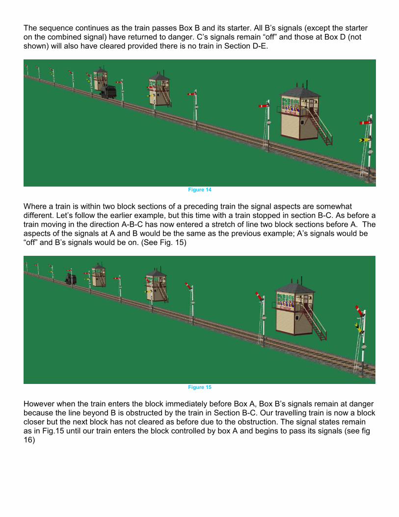
The sequence continues as the train passes Box B and its starter. All B’s signals (except the starter on the combined signal) have returned to danger. C’s signals remain “off” and those at Box D (not shown) will also have cleared provided there is no train in Section D-E.
Figure 14
Where a train is within two block sections of a preceding train the signal aspects are somewhat different. Let’s follow the earlier example, but this time with a train stopped in section B-C. As before a train moving in the direction A-B-C has now entered a stretch of line two block sections before A. The aspects of the signals at A and B would be the same as the previous example; A’s signals would be “off” and B’s signals would be on. (See Fig. 15)
Figure 15
However when the train enters the block immediately before Box A, Box B’s signals remain at danger because the line beyond B is obstructed by the train in Section B-C. Our travelling train is now a block closer but the next block has not cleared as before due to the obstruction. The signal states remain as in Fig.15 until our train enters the block controlled by box A and begins to pass its signals (see fig 16)

Figure 16
Once our train passes B’s distant in the caution position it must be prepared to stop at the next signal, which is B’s home.
Figure 17
In Fig 18 our train is approaching B’s home and is preparing to stop. When it is very close this signal will clear and allow passage as far as B’s starter. The starter will remain “on” until the preceding train has cleared all of C’s signals.
Figure 18

7. Signalling on Single Lines with Passing Loops Signalling of single lines on the block principle works provided the form of signalling shown in Fig. 19 is adopted. The home signal for each direction is placed before the loop and the starter signal before the end of the loop. The distants are placed at a suitable distance in advance of the home signals. The points should be set for the train approaching the loop. If the loop does not include an industry or a passenger active station track markers should be placed, and AI trains should be given instructions to drive to a trackmark, industry or station platform for every loop. Directional track markers should also be placed on each loop to ensure the AI trains keep to the correct side of the loop. Although most single lines were single block sections it is also possible to run AI trains on a multi block single line section provided that the trackmarks are only placed at each passing loop and the driver instructions for all AI trains are to ‘drive to’ or ‘drive via’ each track mark. This is because an AI train will take possession of the points at each end of the single line section and not allow a train to enter the section from the opposite direction until it has cleared the last junction.
Figure 18

8. Colour Light Signals for Block Sections There are four different colour light signals that can be used in block signalling in place of semaphore signals. The ones used on the Settle and Carlisle line are shown in Fig. 20.
Figure 20
The 2AD signal is a two aspect distant signal showing yellow for caution and green for all clear. It was widely introduced on main lines in the UK from about the 1930s as a result of increased line speeds needing placement of distants further away from home signals, in some cases somewhat in excess of a mile. It was beyond the physical capacity of many signalmen to pull the signal wire of a semaphore signal over such a distance. At any signal box a colour light distant could be followed by semaphore or colour light stop signals. However a semaphore distant could only be followed by semaphore stop signals The 2AH was the two aspect equivalent of the stop semaphore signal, showing red for stop and green for all clear. It could be used for the last signal guarding entrance to a block section, normally the starter but at some locations the advanced starter. The 3A signal was a three aspect showing red, amber or green. This signal was not used as the last signal guarding entry to a block section. The 4A signal could be used as any of the stop signals at a signal box.
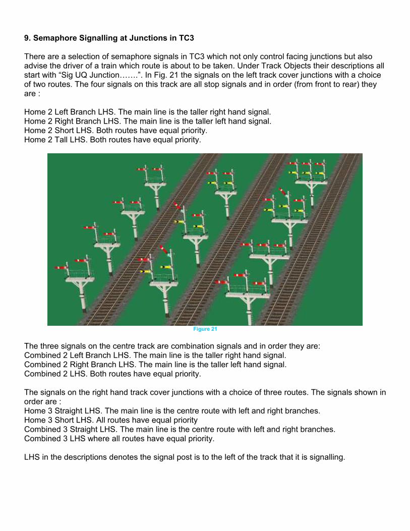
9. Semaphore Signalling at Junctions in TC3 There are a selection of semaphore signals in TC3 which not only control facing junctions but also advise the driver of a train which route is about to be taken. Under Track Objects their descriptions all start with “Sig UQ Junction…….”. In Fig. 21 the signals on the left track cover junctions with a choice of two routes. The four signals on this track are all stop signals and in order (from front to rear) they are : Home 2 Left Branch LHS. The main line is the taller right hand signal. Home 2 Right Branch LHS. The main line is the taller left hand signal. Home 2 Short LHS. Both routes have equal priority. Home 2 Tall LHS. Both routes have equal priority.
Figure 21
The three signals on the centre track are combination signals and in order they are: Combined 2 Left Branch LHS. The main line is the taller right hand signal. Combined 2 Right Branch LHS. The main line is the taller left hand signal. Combined 2 LHS. Both routes have equal priority. The signals on the right hand track cover junctions with a choice of three routes. The signals shown in order are : Home 3 Straight LHS. The main line is the centre route with left and right branches. Home 3 Short LHS. All routes have equal priority Combined 3 Straight LHS. The main line is the centre route with left and right branches. Combined 3 LHS where all routes have equal priority. LHS in the descriptions denotes the signal post is to the left of the track that it is signalling.

For the signal aspect on a junction signal to correctly reflect the state of the junction that it is controlling, targets must be placed on the tracks beyond the junctions. Figs. 22 & 23 show a Home 2 Left Branch LHS signal. The targets used in this case from Trackside Objects are Sig T Feather Left (Pos 1) and Sig T Feather Straight.
Figure 22
When the point is open to the left branch the signal clears for the left branch, provided there is no train in the section ahead. When the lever is reversed for the main line the branch signal goes “on” and the main line is now “off”.
Figure 23
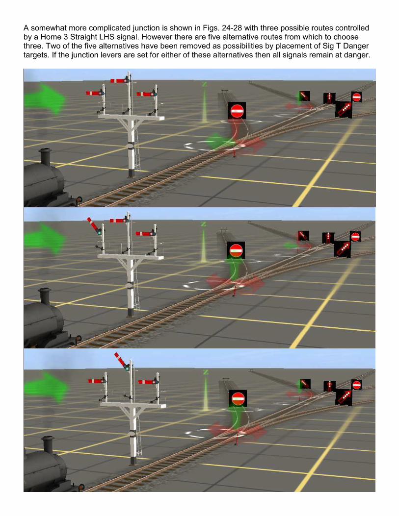
A somewhat more complicated junction is shown in Figs. 24-28 with three possible routes controlled by a Home 3 Straight LHS signal. However there are five alternative routes from which to choose three. Two of the five alternatives have been removed as possibilities by placement of Sig T Danger targets. If the junction levers are set for either of these alternatives then all signals remain at danger.

10. Semaphore Signal Selection in TC3 and Special Signals There are nearly 50 different semaphore signals in the TC3 release. The distant and home signals each come in 3 different types which relate to the post height. The 15 foot height posts were normally used because they are closest to the height of the driver. However the higher posts were often selected to allow for easier sighting by the driver. At a few locations, where the signal needed to be visible from a great distance and also close up, coacting signals were erected. Two of these are shown on the right hand track in Fig. 29. One of these is a combination signal which only needs the distant arm to be sighted closeup. The centre track of the same image shows three cantilever sighting signals. These are placed on or just beyond left hand curves in the track, the positioning of the signal above rather than to the left hand side of the line allows for earlier sighting by the driver.

Figure 29
The left hand pair of tracks show three types of cantilever signals, a distant, a home on a 10 foot post and a home on a 6 foot post. Each cantilever signal appears twice and in all cases the single signal or right hand signal is controlling movement on the right hand track of the pair. The signalling controlling the left hand track is one of the three types of gantry signal which have been placed on the cantilever platform.
Guide prepared by Andrew Howard and Mike Banfield – Version 1.0 – August 2008 Additional information – James Moody
Figures 3,4, and 5 adapted from original illustrations by Rob Shaw