Gas Line Maintenance & Safety Practices in Bokaro Steel Plant
Upload
prashant-kumarCategory
view
423download
101
Chapter-01
INTRODUCTION
1.1 Company Overview
Fig.-1.1 SAIL
Steel Authority of India Limited (SAIL) is one of the largest state-owned steel making
company based in New Delhi, India and one of the top steel makers in world. It has an
annual turnover of 49350 crore (2012-13) . It is a public sector undertaking which₹
trades publicly in the market. SAIL is largely owned by Government of India and acts
like an operating company. Incorporated on 24 January 1973, SAIL has 101,878
employees (as on 31-Mar-2013). With an annual production of 13.5 million metric tons,
SAIL is the 24th largest steel producer in the world. SAIL's wide range of long and flat
steel products are much in demand in the domestic as well as the international market.
This vital responsibility is carried out by SAIL's own Central Marketing Organization
(CMO) that transacts business through its network of 37 Branch Sales Offices spread
across the four regions, 25 Departmental Warehouses, 42 Consignment Agents and 27
Customer Contact Offices. CMO‟s domestic marketing effort is supplemented by its
ever widening network of rural dealers who meet the demands of the smallest customers
in the remotest corners of the country. With the total number of dealers over 2000,
SAIL's wide marketing spread ensures availability of quality steel in virtually all the
districts of the country.
SAIL's International Trade Division ( ITD), in New Delhi- an ISO 9001:2000 accredited unit of CMO, undertakes exports of Mild Steel products and Pig Iron from SAIL‟s five integrated steel plant.
Total Assets Rs. 91961 crore
[2]
No. of employees 97,897(as on 31-March-2014)
Table1.1-SAIL Specification
MAJOR UNITS OF SAIL
Integrated Steel Plants :
PLANT LOCATION
Durgapur Steel Plant (DSP) Durgapur , West Bengal
Bhilai Steel Plant (BSP) Bhilai , Chhattisgarh
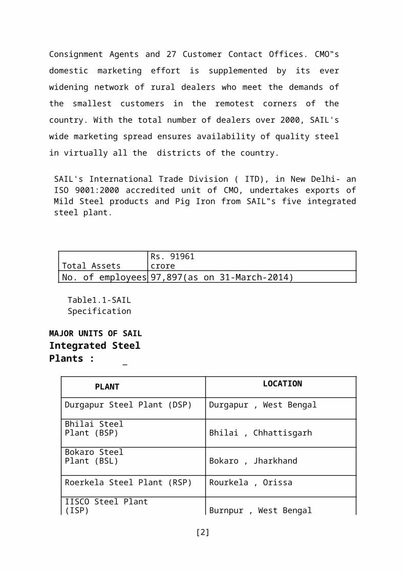
Bokaro Steel Plant (BSL) Bokaro , Jharkhand
Roerkela Steel Plant (RSP) Rourkela , Orissa
IISCO Steel Plant (ISP) Burnpur , West Bengal
Table1.2-Integrated Plant Special Steel Plants :
PLANT LOCATION
Alloy Steel Plant (ASP) Durgapur , West Bengal
Salem Steel Plant (SSP) Salem , Tamil Nadu
Visvesvaraya Iron & Steel Plant (VISP) Bhadravati , Karnataka
Table1.3-Special Plant
Subsidiary Plant :
PLANT LOCATION
Plant for producing Ferro Alloys Chandrapur
Table 1.4- Subsidiary Plant
MAJOR JOINT VENTURES:
[3]
NTPC-SAIL Power Company Pvt. Ltd.
JV with NTPC for operating & managing CPPs of Durgapur, Rourkela & Bhilai. Bokaro Power Supply Company Pvt. Ltd JV with DVC for managing & operating power plant at
Bokaro. Mjunction
JV with Jaiprakash Associates Ltd. For setting up slag based cement plant of 2.2 million tone per annum capacity with grinding unit at Bhilai & clinkering unit at Satna.
Production at clinkering unit already started Cement production at Bhilai shall commence shortly.
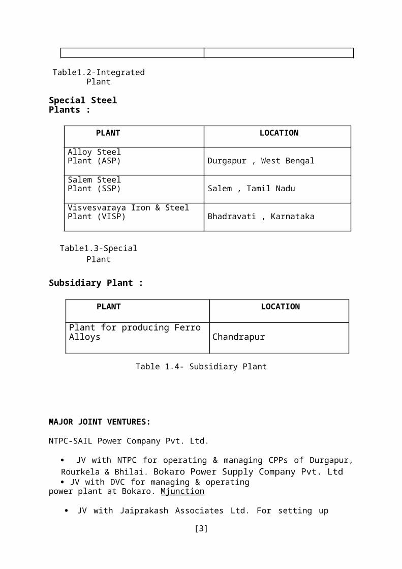
BOKARO STEEL PLANT
Fig.1.2- BSL
Bokaro Steel Plant is located in the Bokaro district of Jharkhand . It is the fourth integrated public sector steel plant in India built with Soviet help. It was incorporated as a limited company in 1964. It was later merged with the state-owned Steel Authority of India Limited (SAIL).
Type State owned enterprise public companyIndustry Steel
[4]
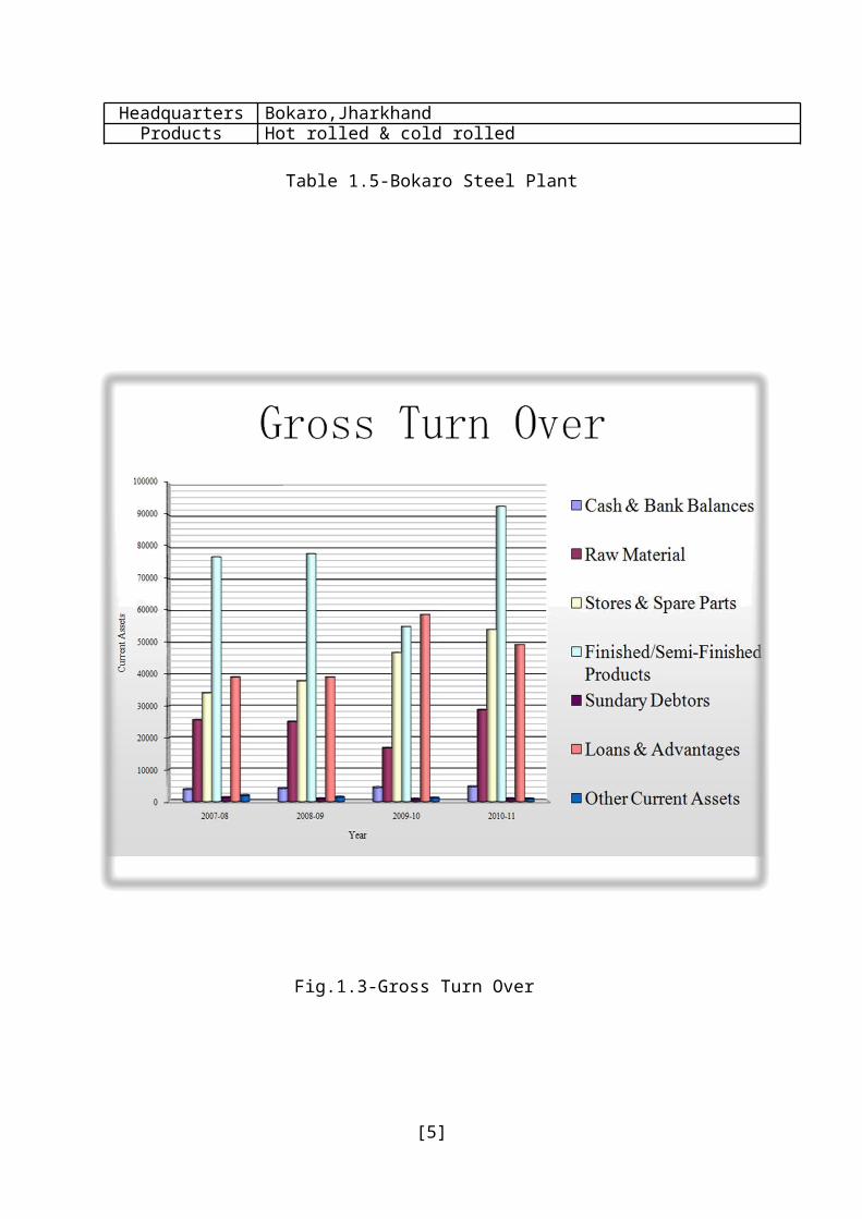
Founded 1964Headquarters Bokaro,Jharkhand
Products Hot rolled & cold rolled
Table 1.5-Bokaro Steel Plant
Fig.1.3-Gross Turn Over
1.2 Facilities in Bsl:
[5]

Raw material & material handling plant Coke oven & byproduct plant Blast furnace Steel melting shop Continuous casting shop Slabbing mill Hot strip mill Hot rolling coil factory Cold rolling mill Auxiliary shops.
Chapter-02
Raw Material
[6]
2.1 Raw Material Handling PlantRaw Material Handling Plant or Ore Handling Plant or Ore Bedding and Blending Plant play a very important role in an Integrated Steel Plant. It is the starting point of an integrated steel plant, where all kinds of raw materials required for iron making/steel making are handled in a systematic manner, e.g., unloading, stacking, screening, crushing, bedding, blending, reclamation, etc.
Different types of major raw materials used in an integrated steel plant are: Iron Ore Lime stone Dolomite Manganese Ore Ferro and Silico manganese Quartzite and Coal
For Blast Furnace route Iron Making the main raw materials required are: Iron ore lump Blast furnace grade lime stone Blast furnace grade dolomite Coke Sinter Scrap LD Slag Mn Ore Quartzite
The main objective of raw material handling plant/ore handling plant/ore bedding and blending plant is to
homogenize materials from different sources by means of blending supply consistent quality raw materials un-interruptedly to different customers maintain buffer stock unloading of wagons/rakes within specified time norm raw material preparation (like crushing , screening etc.).
The main functions of RMHP are : unloading& stacking of raw materials screening of iron ore lump & fluxes crushing of coke/flux and base mix preparation dispatch of processed inputs to customer units Crushing of coke/flux and base mix preparation Dispatch of processed inputs to customer units
[7]

2.2 Benefits of RMHP:
Provides consistent quality raw materials to its customer and also controlling the cost by :
Minimizing undersize in iron ore lump & flux by means of screening Consistency in chemical & physical analysis by means of bedding & blending Input quality over a time period is known Metallurgical waste utilization
2.3 Coke Ovens & By-Product Plant:
[8]

Coke making is the process of convert coking coal, through a series of operations, into metallurgical coke. The process starts from unloading of the coal at the wagon tipplers and ends at sizing & transportation of coke to the Blast Furnace. The success of Blast Furnace operation depends upon the consistent quality of coke, which isused in Blast Furnace. The quality of coke depends upon the precarbonisation technique,carbonization & post-carbonisation techniques used in Coke ovens. Precarbonisation technique is controlled by Coal handling Plant
2.4 Types & Sources of Coking Coal:All coals are not coking coals, i.e. all types of coal can’t be used for coke making. Cokingcoals are classified as:
Prime Coking Coal (PCC) Medium Coking Coal (MCC)
These are generally known as Indigenous coal, i.e. available in India. In addition to theabove coking coal the following types of coal are also used for coke making in all SAILplants.
Imported Coking Coal (ICC) – Hard Soft Coking Coal (SCC)
Coal is extracted from coal mines & processed in the coal washeries to lower down the ashcontent to make it fit for coke making.The different sources of coal are named after the respective washeries and are as follows:PCC
Bhojudih Sudamdih Munidih Patherdih Dugda Mahuda
MCC Kathra Swang Rajrappa Kedla Nandan
ICC (Hard) » Australia» New Zealand » USA
SCC » Australia
Types & Sources of Coking Coal:
[9]

All coals are not coking coals, i.e. all types of coal can’t be used for coke making. Cokingcoals are classified as:
» Prime Coking Coal (PCC)» Medium Coking Coal (MCC)
These are generally known as Indigenous coal, i.e. available in India. In addition to theabove coking coal the following types of coal are also used for coke making in all SAILplants. Imported Coking Coal (ICC) – HardSoft Coking Coal (SCC)Coal is extracted from coal mines & processed in the coal washeries to lower down the ashcontent to make it fit for coke making.
2.5 Properties of Coking Coal
» Percentage of Ash: Lower the ash percentage better is the coal. Indian coal normally contains a high percentage of ash. This is reduced to some extent by suitable beneficiation process at the mines.
» Volatile Matter (VM): This is the volatile matters present in the coal which goes out as gas during carbonization.
» Free Swelling Index (FSI): This shows the agglomerating nature of coal on rapid heating.
» LTGK: This is another test for agglomerating behaviour of coal. However this is done at a slower rate of heating.
» Inherent Moisture: This gives a very good idea about the rank of the coal with advancement of rank the inherent moisture generally comes down.
» Mean Max Reflectance: Rank of coal is determined by measuring the reflectance of coal,which is determined by MMR value. MMR is directly proportional to the strength of Coke.
Coal Ash VM FSI LTGK InherentMoisture
MMR
PCC 19.0 21-23 >3.5 >E 2.5-3.0 1.10MCC 18.5 23-25 >3.0 >E 2.5-3.0 0.85Soft 8-10 25-30 >5.0 >G 2.5-3.0 0.87
Aust Hard 8-10 18-20 >5.0 >G 2.5-3.0 1.25NZ 3-4 25-28 >5.0 >G 2.5-3.0 1.25
USA 8-10 25-30 >5.0 >G 2.5-3.0 1.00
Table 2.1- Type of Coal Content
[10]
Main parts of coke oven
Fig.- 2.1 Process flow Diagram(Coke Oven)
[11]
Coke oven1.Coal handling plant(CHP)2.Battery3.Coke sorting plant4.By Product plantCoal tar(40,000RS/TON)ammonia for fertilizersbenzolbenzene(used for fuel in air craft)1,10,000/TONnapthasluphuric acid

Fig.-2.2 Silos Fig.-2.3 Coke Oven Battery
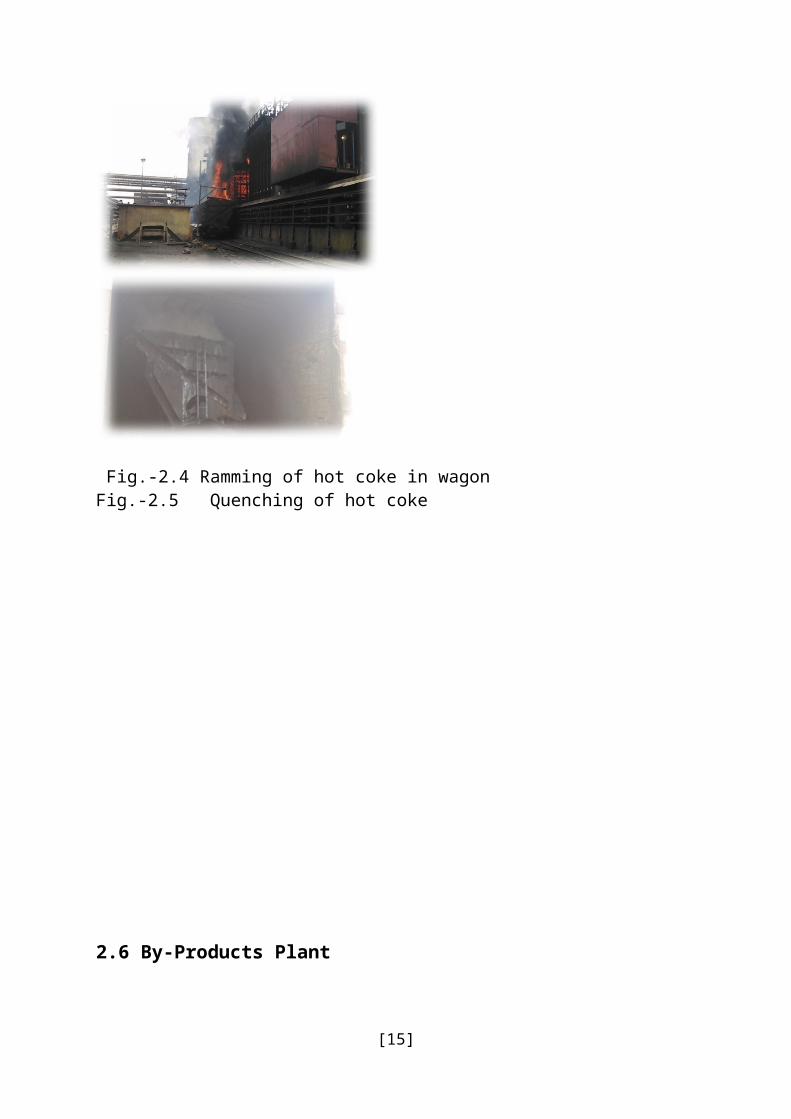
Fig.-2.4 Ramming of hot coke in wagon Fig.-2.5 Quenching of hot coke
[12]

2.6 By-Products Plant
Process of heating coal in absence of air to produce coke is called coal carbonization or destructive distillation. Purpose of coal carbonization is to produce coke whereas by-product is coke oven gas.From coke oven gas, various by products like tar, benzol, naphthalene, ammonia, phenol, anthracene etc. are produced. Generally high temperature coal carbonization is carried out in coke oven battery of integrated steel plants at temp of 1000-1200°C.Coke produced in the coke oven battery is sized, crushed and screened to different fraction as per requirement:-
» 25- 80 mm size- Metallurgical coke required for iron making in Blast Furnace.» 15-25 mm size- Nut/Pearl coke partly required for internal use and rest is sold out.» 0-15 mm size- Coke breeze, mostly used for making sinter.
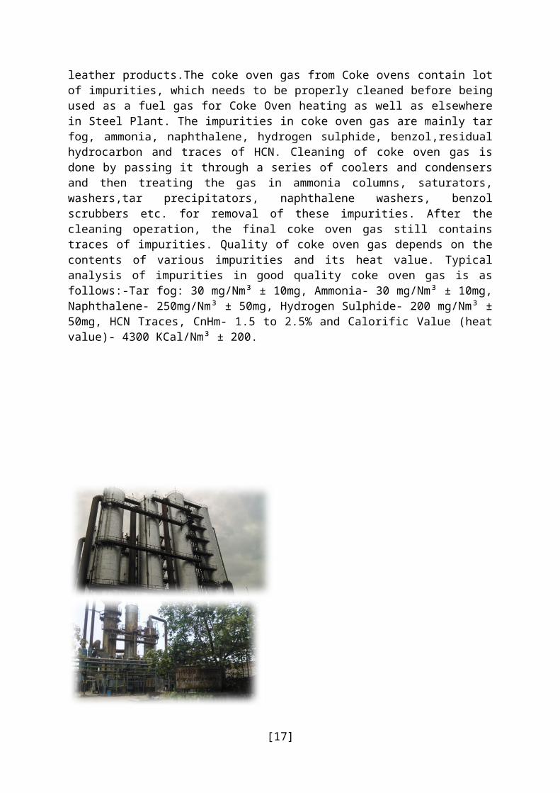
In the by-product plant major by-products like tar, ammonia and crude benzol are recovered from the coke oven gas evolved during coal carbonization. The output of the chemical products and their composition and properties of the coal depend on the blend used for coking, the heating regime and the operating condition of the battery.Tar separated out of coke oven gas as a mixture of large quantities of various chemical compounds.Out of tar, a number of compounds, which have market demand, are separated in the tar distillation plant. Among the tar products, naphthalene is the costliest item and its yield is 50-55 % of the tar distilled. Other tar products are road tar, wash oil, pitch creosote mixture, medium hard pitch and extra hard pitch etc.Ammonia in the coke oven gas is recovered as Ammonium sulphate, which is used as a fertilizer in agriculture sector. Output of crude benzol depends on the VM content in the coal blend andtemperature of coking. Light crude benzol is rectified in benzol rectification plant and the benzol products obtained are benzene, toluene, xylene, solvent oil etc. Yield of benzol products varies from 86-88% of the crude benzol processed. The by-products recovered in the process are very important and useful .Tar is used for road making and as fuel in furnaces. Pitch is used for road making. The benzol products like benzene, toluene, phenol, naphthalene and xylene etc. are important inputs for chemical industries producing dyes, paint, pharmaceutical, insecticide, detergent, plasticiser and leather products.The coke oven gas from Coke ovens contain lot of impurities, which needs to be properly cleaned before being used as a fuel gas for Coke Oven heating as well as elsewhere in Steel Plant. The impurities in coke oven gas are mainly tar fog, ammonia, naphthalene, hydrogen sulphide, benzol,residual hydrocarbon and traces of HCN. Cleaning of coke oven gas is done by passing it through a series of coolers and condensers and then treating the gas in ammonia columns, saturators, washers,tar precipitators, naphthalene washers, benzol scrubbers etc. for removal of these impurities. After the cleaning operation, the final coke oven gas still contains traces of impurities. Quality of coke oven gas depends on the contents of various impurities and its heat value. Typical analysis of impurities in good quality coke oven gas is as follows:-Tar fog: 30 mg/Nm³ ± 10mg, Ammonia- 30 mg/Nm³ ± 10mg, Naphthalene- 250mg/Nm³ ± 50mg, Hydrogen Sulphide- 200 mg/Nm³ ± 50mg, HCN Traces, CnHm- 1.5 to 2.5% and Calorific Value (heat value)- 4300 KCal/Nm³ ± 200.
[13]

Fig.-2.6 BY Product plant
[14]
2.7 Sinter Plant:A large quantity of fines is generated in the mines which cannot be charged directly into the Blast furnace. Moreover many metallurgical wastes are generated in the steel industry itself, disposal of which is very difficult. In order to consume this otherwise waste fine material, they are mixed with Iron ore fines and agglomerated into lumps by a process known as SINTERING. Sintering is the process for agglomeration of fine mineral particles into a Porous and lumpy mass by incipient fusion caused by heat produced by combustion of solid fuel within the mass itself.
Fig.-2.7 Classification of Sinter Plant
2.7.1 Raw Materials
Raw materials used in Sinter Plant are:-» Iron ore fines» Limestone fines» Dolomite fines» Coke breeze fines» D.O.F. sludge» Burnt lime» Mill scale fines» B.O.F. slag» Blast Furnace return fines/Inplant return fines
The scheme for preparation of charge first envisages blending of raw materials in raw materials yard to obtain consistency in the chemical composition and size fraction of raw materials. After this raw materials are received in raw material receiving bins. Preliminary proportion is done at the receiving bins and then the raw materials are transported to stock bins where final and accurate proportioning is done. Normally constituents proportioned are Iron ore fines, Flue dust, Mill scale, Lime stone fines,Dolomite fines, LD dust and Return sinter (as Re-circulating load). It can be seen that sinter plant can make adequate use of almost all the valuable metallurgical wastes arising in an integrated steel plant,thus paving the way for valuable conservation of minerals and techno-economic benefits.An accurate proportioning is envisaged to be done at the stock bins. Here the constituentsproportioned may consist of:-
» Ore fines comprising mixture of ore fines and mill scales.» Flux consisting of mixture of lime stone and dolomite in the ratio of approximately
3:1 to obtain optimum MgO content in the sinter and also CaO contents in the sinter.» Crushed Coke fines.» Return sinter as re-circulating load (BF sinter return & in plant sinter).
[15]
Stock Bins

» Following Approximate charge proportion will be required to make one ton of sinter (Wet basis):-
» Ore fines : 817 kg» Coke : 78 kg» Mill scale + fines: 16kg» Lime stone : 86 kg» B.O.F. Sludge : 2kg» B.O.F. Slag : 20kg» Dolomite : 83kg» Burnt Lime: 04 to16 kg
Sinter return : 30 to 40 % (BF sinter return + In plant sinter return
2.7.2 Preparation of charge mix:Preparation of charge mix mainly consists of crushing of fluxes, solid fuels, proper sizing of them and mixing with iron Ore fines in a certain ratio to prepare base mix. Experience of operation of sinter plants has demonstrated that the fluxes namely lime stone & dolomite fines should be crushed to obtain 90% minimum(-3mm fraction).Such finely crushed fluxes result in the formation of strong sinter due to absence of free lime. As in the case of fluxes, careful preparation of coke breeze to the extent of 90% minimum (-3mm fraction) is an essential pre-requisite for producing high quality sinter. Normally for crushing of coke breeze, Roll crushers are used which ensures better and consistent crushing and also preferred due to easy maintenance. Finally these finely crushed coke and fluxes are mixed with ore fines(called as a BASE MIX) in required proportion in balling/nodulising drum where atomized water is added .The purpose of balling/nodulising drum are homogenising of base mix and formation of balls. This base mix is then loaded on moving sinter machine pallets through belt conveyors and segregation plates. The purpose of segregation plate is to segregate the base mix such that coarser particles falls in the bottom of sinter machine, medium particles in middle portion and smaller particles at the top by rolling effect. Before loading base mix on sinter machine, a layer of return sinter (namely hearth layer) is loaded on pallets forming the bottom most portion of the charge just above the pallet grates. This hearth layers helps in preventing burning of grate bars apart from getting optimum under grate suction.
2.7.3 Sinter making:Sintering of fines by the under grate suction method consists of the mixing of fines with finely crushed coke as fuel and loading the mixture on the pallet grates. Ignition of the fuel proceeds on the surface of charge by a special ignition arrangement, called ignition furnace (where gaseous fuel is burnt to produce high temperature to ignite the fuel in sinter mix). The gases used in ignition furnace are mainly coke oven gas and mixed gas. Mixed gas is combination of coke oven gas and blast furnace gas. Further the combustion is continued due to suction of air through the layers of the charge by means of Exhausters. Due to this, the process of combustion of fuel gradually moves downwards up to the grates.From the scheme obtained in a few minutes after ignition, it is observed that the sintering process can be divided into six distinct zones:-
» Zone of Cold Sinter (60 to 100 degree Celsius)» Zone of hot Sinter (100 to 1000 degree Celsius)» Zone of intensive combustion of fuel (1000 to 1350 degree Celsius)
[16]
» Heating zone (1000 to 700 degree Celsius)» Zone of Pre-heating of charge (700 to 60 degree Celsius)» Zone of Re-condensation of moisture (60 to 30 degree Celsius)
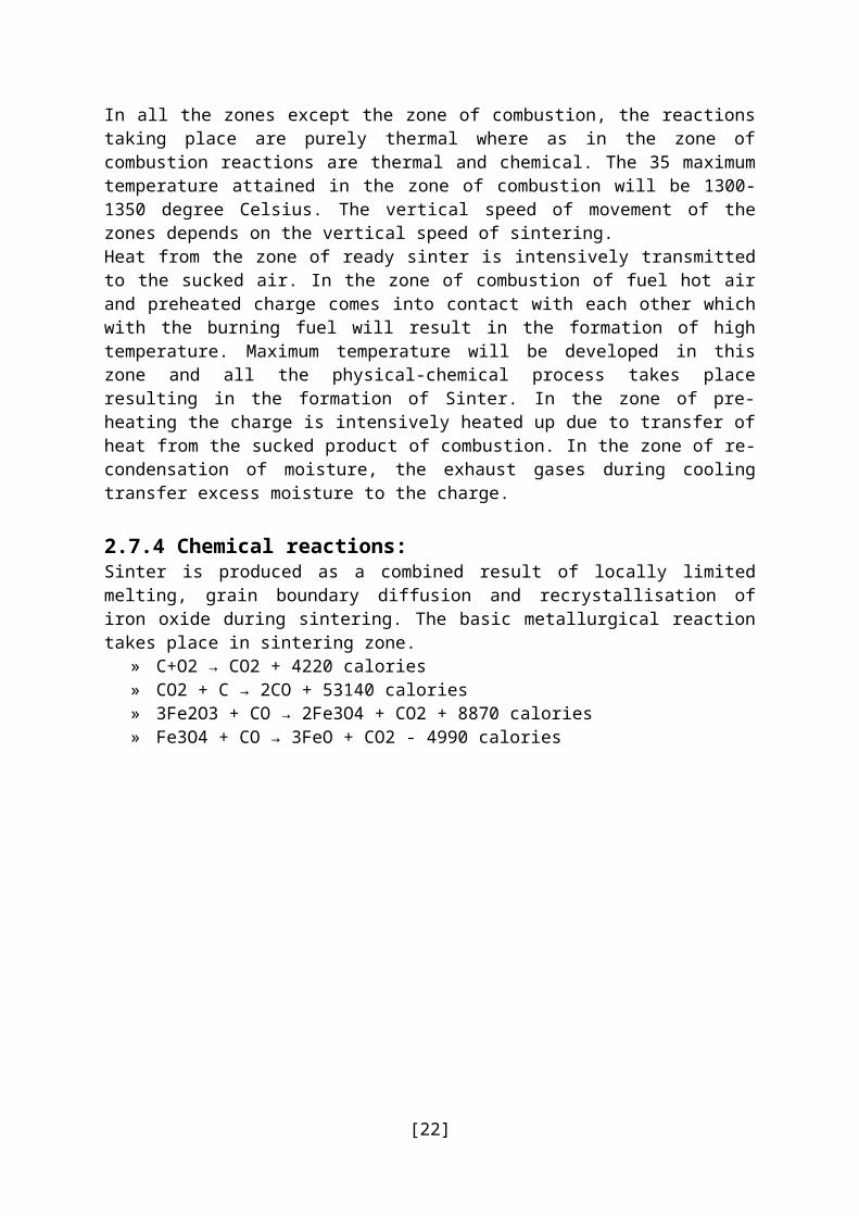
In all the zones except the zone of combustion, the reactions taking place are purely thermal where as in the zone of combustion reactions are thermal and chemical. The 35 maximum temperature attained in the zone of combustion will be 1300-1350 degree Celsius. The vertical speed of movement of the zones depends on the vertical speed of sintering.Heat from the zone of ready sinter is intensively transmitted to the sucked air. In the zone of combustion of fuel hot air and preheated charge comes into contact with each other which with the burning fuel will result in the formation of high temperature. Maximum temperature will be developed in this zone and all the physical-chemical process takes place resulting in the formation of Sinter. In the zone of pre-heating the charge is intensively heated up due to transfer of heat from the sucked product of combustion. In the zone of re-condensation of moisture, the exhaust gases during cooling transfer excess moisture to the charge.
2.7.4 Chemical reactions:Sinter is produced as a combined result of locally limited melting, grain boundary diffusion and recrystallisation of iron oxide during sintering. The basic metallurgical reaction takes place in sintering zone.
» C+O2 → CO2 + 4220 calories» CO2 + C → 2CO + 53140 calories» 3Fe2O3 + CO → 2Fe3O4 + CO2 + 8870 calories» Fe3O4 + CO → 3FeO + CO2 - 4990 calories
[17]

Chapter-03
Melting Process
3.1 Blast Furnace:BF is a counter current heat and mass exchanger, in which solid raw materials are charged from the top of the furnace and hot blast, is sent through the bottom via tuyeres. The heat is transferred from the gas to the burden and oxygen from the burden to the gas. Gas ascends up the furnace while burden and coke descend down through the furnace. The counter current nature of the reactions makes the overall process an extremely efficient one in reducing atmosphere. The real growth of blast furnace technology came with the production of high strength coke which enabled the construction of large size blast furnaces.
3.2 Raw Materials and their Quality:
The different raw materials used in the Blast Furnaces are:-
Iron ore: Iron bearing materials; provides iron to the hot metal. Iron ores is available in the
» form of oxides, sulphides, and carbonate, the oxide form known as hematite (red in colour) is
» mostly used in SAIL plants. It is the principal mineral in blast furnace for extraction of pig iron,
» generally rich in iron content varying from 62% to 66% associated often with naturally
» occurring fines (-10MM) to the extent of 20%. Although relatively free from impurities like
» phosphorous, sulphur and copper, they have high alumina content, high alumina/ silica ratio
» of about 2 or more. The high alumina content makes the slag highly viscous and creates
» problems for stable furnace operation. Limestone: It acts as flux. Helps in reducing the melting point of gangue present in
the iron» bearing material and combines effectively with acidic impurities to form slag in iron
making. Quartzite: It acts as an additive .Quartzite is a mineral of SiO2 (silica) and under
normal» circumstances contains about 96-97% of SiO2 rest being impurities. Quartzite plays
its role in» counteracting the bad effects of high alumina in slag. Manganese ore: It acts as additive for the supply of Mn in the hot metal. Mn ore is
available in the form of combined oxides of Mn and Fe and usual content of Mn is about
[18]

» 31-32% for steel plant use. However Mn ore available with SAIL is having high alkali contents so it should be used judicially.
» Coke: It acts as a reductant and fuel, supports the burden and helps in maintaining permeable bed. Coke (metallurgical) used in blast furnace both as fuel & reducing
agent. The Indian coal is characterized by high ash (25-30%) and still worse, a wide fluctuation in ash content, poor coke strength leading to excessive generation of fines, rapid fluctuation in moisture content etc. the problem of poor quality coke has been tackled by adding imported coal (09-11%) in the indigenous coal blend to get a coke ash of 14-19 %.
» Sinter: It is iron bearing material. Fines that are generated in the plant/mines are effectively utilized by converting them to sinter. It provides the extra lime required for the iron ore and coke ash that is charged in the blast furnace. Sintering is the process of agglomeration of fines (steel plant waste and iron ore fines) by incipient fusion caused by heat available from the coke contained in the charge. The lumpy porous mass thus obtained is known as “sinter”.
» Pellets: It is also an iron bearing materials. There is a proposal to utilize the micro-fines which cannot be used for sinter making can be used for pellet manufacturing and the pellets formed will be charged in the BF.
» Coal dust Injection: It acts as an auxiliary fuel, reduces coke consumption in the bf. The coal is injected through the tuyeres.
» Coal tar Injection: It acts as an auxiliary fuel, reduces coke consumption in the bf. The tar is injected through the tuyeres.
Fig.- 3.1 Blast Furnace
[19]

Fig.-3.2 Blast furnace Controls
[20]

3.3 Primary Steel Making:
The Hot Metal which is produced by Blast Furnaces consists of various impurities. Main impurity present is Carbon and other impurities like phosphorus, sulphur, silicon, non-metallic inclusions etc.are also present. Steel making is the process of purification of this Hot Metal. Steel such produced Is the pure form of metal. Hot Metal contains around 4% of Carbon which is reduced below 0.10% as per the requirement. Other impurities like sulphur, phosphorus are removed and alloying elements such as manganese, nickel, chromium and vanadium are added to produce the exact steel required. The schematic view and various processes involved in steel making are as follows:-
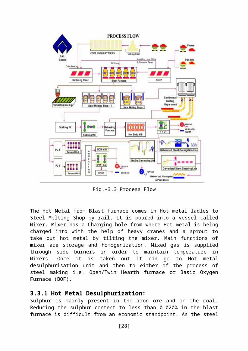
Fig.-3.3 Process Flow
The Hot Metal from Blast furnace comes in Hot metal ladles to Steel Melting Shop by rail. It is poured into a vessel called Mixer. Mixer has a Charging hole from where Hot metal is being charged into with the help of heavy cranes and a sprout to take out hot metal by tilting the mixer. Main functions of mixer are storage and homogenization. Mixed gas is supplied through side burners in order to maintain temperature in Mixers. Once it is taken out it can go
[21]
to Hot metal desulphurisation unit and then to either of the process of steel making i.e. Open/Twin Hearth furnace or Basic Oxygen Furnace (BOF). 3.3.1 Hot Metal Desulphurization:Sulphur is mainly present in the iron ore and in the coal. Reducing the sulphur content to less than 0.020% in the blast furnace is difficult from an economic standpoint. As the steel quality often requires a sulphur content of 0.010%, the hot metal must be desulphurized in another way. In desulphurization methods alone lime, or magnesium reagent, and calcium carbide may be used in proper proportion.They are injected into the metal with a special designed lances under a gaseous stream. In this way,the sulphur content can be reduced to levels below 0.005 %. Hot metal in a ladle bring to Desulphurization unit by EOT cranes or rail. After proper positioning of the ladle, injection lance is lowered deep into the metal. Then start injection of the said material through the lance and is continued for 5 to 10 minutes depending on sulphur content in hot metal. Ladle is then taken to slag racking machine to remove the slag formed during the injection process. Hot metal is then sent to converter.
3.3.2 Basic Oxygen Furnace (BOF/LD Converter):Basic Oxygen Furnace is commonly known as BOF process or LD process. It is named so because this process was developed in LINZ and DONAWITZ, two cities in Austria. As compared to open / twin hearth process is fast, energy efficient and simple. Tap to tap time in BOF is around 45-50 minutes. The name BOF is derived from the manner in which the compositional adjustments are achieved.Oxygen is the reagent that is used to remove most of the undesirable elements via a number of complex oxidation processes. Basic refers to the fact that the reaction takes place in a Vessel called converter lined with basic refractory.
The major input materials in BOF or LD converter are:-» Metallic: Hot metal containing around 4% carbon is the main input in the BOF. Scrap
is also used as a coolant and is also used in the process.» Fluxes: Fluxes such as lime, dolomite, iron ore etc. are used in the process for slag
making.» Oxygen: one of the important inputs comes mainly from captive Oxygen plants in
addition to the Purchased liquid oxygen. Oxygen Purity should be more than 99.0%.» Nitrogen: It is not directly taking part in the process but used for purging and ceiling
purpose.It is also used for slag splashing.» Ferro-Alloys: while tapping the steel Ferro-alloy such as Fe-Si, Si-Mn, Fe-Mn etc. are
being added to make the desired grade of steel.
The process followed in BOF/LD Converter is as follows:-» Mixer and Desulphurization: The process start with mixer in steel melting shop. Metal
is stored in Mixers and it is taken out as and when needed. Before charging it into BOF, external desulphurization is done as per requirement to reduce Sulphur content in Hot metal. Calcium carbide, lime powder, magnesium compound are injected into hot metal through a lance with Nitrogen pressure. After compound injection is over slag racking is done to remove the slag which is necessary to avoid reversal of sulphur.
» Converter blowing: The process of blowing means reaction of Oxygen with hot metal and fluxes in LD converter. The hot metal along with scrap is charged into converter with the help of EOT cranes by tilting the converter. A typical composition of Hot
[22]

metal is C- 4.0%, Si-0.60%, Mn-0.10 %, P- 0.15%, S-0.050% and temperature is around 1300˚C. After chargingconverter is kept vertical and lance is lowered in the converter through which oxygen is blown at a pressure of around 14 kg/cm2. During the blowing process fluxes such lime, calcined dolomite, iron ore etc. are added to make slag. The most important flux is lime. The slag is basic in nature. Main impurities carbon reacts with oxygen and is removed in the gaseous form. Impurities like Si, P, S and other non-metallic impurities are removed in the form of slag,which is lighter than metal so it floats on metal surface. The blowing process usually takes 17minutes. When the blowing is complete converter is tilted to take out the slag in a slag pot.Sample and temperature is also taken manually. At the end of the blow the temperature is generally in the range of 1650˚C - 1690˚C and a typical bath analysis is C-0.07 %, Mn-0.08 %,P-0.020 %, S- 0.030 %. When the desired composition and temperature is achieved the steel is tapped.
» Tapping: tapping means discharging the liquid steel into ladle through the tap hole present in the converter by tilting it. As per the grade of steel the Ferro-alloys are also added into ladle during tapping. As soon as the steel finishes the converter is lifted and tapping is complete.
» Nitrogen Slashing: After tapping, the residual slag in the converter is splashed with the help of nitrogen. Converter is kept vertical and lance is lowered. Through the same lance nitrogen is blown which splashes the basic residual slag in the converter and gives a coating on the refractory bricks. Main advantage of nitrogen splashing is to increase the lining life of the converter.
» Chemical Reactions: There are a lot of complex chemical reactions taking place in the BOF during blowing. Main reactions in simplified form are given below –» Fe + O = FeO» C + O = CO/CO2» Si + 2O = SiO2» Mn + O = MnO» 2P + 5O =P2O5»
» Slag Composition: The slag formed during the BOF process is basic in nature. It is a complexoxide compound of Ca along with Si, P and other non-metallic inclusions. A typical slag analysis at the end of the blowing is as follows –» CaO= 45-50%,» MgO= 9-11%,» FeO= 15-20%» Basicity= CaO/SiO2 ≥ 3.0
» Refractories: Refractory plays a very important role in BOF shop. As liquid metal is handled inBOF Shop so all vessels like mixer, converter, ladles etc. are lined with refractory bricks. It protects the shell of vessel and retains the metal temperature. Different types of refractory as per their usage are given below –» Converter Vessel: The bricks used here are basic in nature. Dolomite bricks or
magnesia carbon bricks are commonly used in converter. In recent times magnesia carbon bricks have replaced dolomite bricks. Number of heats made in a converter from one new lining to next lining is known as the lining life of the converter.Nowadays all plants are trying to achieve higher lining life. The tap hole in theconverter is also made up of refractory, which wears with number of heats tapped. It
[23]
is changed from time to time.» Mixer: The bricks used here are normally high alumina and magnesite bricks are used.» Ladles: The small vessel which carry Hot Metal for charging the converter are called
hot metal ladle. They are lined with high alumina bricks. The steel is tapped in steel ladles. This ladle carries steel to secondary refining and finally for casting. The bricks used are again high alumina and magnesia carbon.
3.3.3 Major Equipment in the BOF shop are:-
Converter: A converter is an open pear shaped vessel made of steel and lined from inside with basic refractory bricks. It can be rotated through 3600. Charging and deslagging is done through mouth whereas tapping of steel is done through a hole called tap hole.
Lance: It is made of three concentric steel tubes to circulate water around the center tube and pass oxygen through the innermost tube. Its tip is made of copper. Always a stand by lance is provided in a converter.
Gas Cleaning Plant: A huge quantity of waste gases with high temperature and containing dust particles, generated during the process is passed through the GCP. Primarily water is sprayed over the gases to separate the solid particles and to cool them. Cleaned gases are either collected in a gas holder or burnt in the atmosphere to control air pollution.
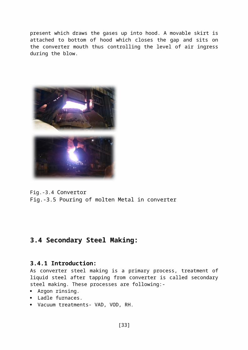
A large water cooled hood sits above converter. The vast quantity of waste gas produced during steel making pass through hood and then collected and cleaned. An ID fan is present which draws the gases up into hood. A movable skirt is attached to bottom of hood which closes the gap and sits on the converter mouth thus controlling the level of air ingress during the blow.
Fig.-3.4 Convertor Fig.-3.5 Pouring of molten Metal in converter
[24]

3.4 Secondary Steel Making:
3.4.1 Introduction:As converter steel making is a primary process, treatment of liquid steel after tapping from converter is called secondary steel making. These processes are following:- Argon rinsing. Ladle furnaces. Vacuum treatments- VAD, VOD, RH.
3.4.2 Objective:The objectives of secondary steel making are:- Homogenization of liquid steel composition and temperature. Achievement of correct temperature of liquid steel for subsequent casting. Achievement of correct chemical composition by means of trimming addition. Removal of dissolve gases of liquid steel by vacuum process.As argon rinsing and ladle furnace are not vacuum processes, they can achieve only first three objectives. VAD, VOD & RH are vacuum processes and achieve the fourth objective.
3.4.3 Secondary Refining Practices:There are varied categories of secondary steel making facilities that are available in the world today. Broadly, secondary steel making units categorized are based on (a) Stirring Systems (b) Ladle Heating Systems (c) Vacuum Degassing Systems and (d) Injection Systems. The application of a particular unit for the melt shop depends upon the specific needs of the plant and the product made. However, it is the final product that determines the choice of the process.
3.4.4 Stirring systems:These systems involve in stirring the molten steel bath for obtaining homogenous temperature, composition, inclusion floatation and promotion of slag-metal refining reaction. Stirring systems are further classified as Ladle Stirring and Vessel Stirring.
Ladle Stirring: Here, stirring is carried out either by gas or by electro-magnetic methods. Gas Stirring process is a method where stirring is done through injection of inert gas into the steel bath. Stirring results from the expansion of gas due to heating and decrease in pressure as the gas rises. One of the methods is injection of inert gas through deeply inserted refractory lancefrom the top in to the molten steel bath. These lances may be of T, Y or straight bore type.Initially, nitrogen was used as medium for purging that resulted in increased nitrogen pick upin steels. This led to application of argon gas for stirring to produce steels with low nitrogen.Gas stirring by purging argon through the porous plug located at the bottom of the ladle hasevolved as the most effective method of gas stirring. From the simple argon purging from porous plug, further developments took place in the form of using snorkel over the steel bathby sealed argon bubbling and provision of composition adjustment through the process known as CAS method. Here, the slag remains undisturbed and limits the detrimental effectsof primary furnace slag contamination like poor recovery of aluminium, increased phosphorous reversion etc. The best advantages of gas stirring method can be accrued through mixing a basic reducing slag with steel in the inert environment to simultaneously
[25]

achieve de-oxidation & de-sulphurisation. Also, the argon stirring helps in reducing the hydrogen content and improves the cleanliness of the steel by floatation of oxide inclusions.Electro-Magnetic Stirring process is a stirring method involving induction stirring through electro-magnetic coils positioned close to the ladle. Here, the supply of turbulent currents through the coils diametrically at 1/3rd and 2/3rd of the ladle depth below the surface of the molten steel induces stirring action. This method provides lower stirring energy than the gas stirring system with better stirring energy distribution with controlled stirring action. The stirring system is reported to be an excellent process for floatation and separation of nonmetallic inclusions.
Fig.-3.6 Pouring of steel for convertor into ladle
Vessel Stirring: One of the most popular secondary steel making process for stainless steel production is through Argon Oxygen De-carburization (AOD) unit. It is a low cost stainless steel production method that can absorb large amounts of scrap and high carbon ferrochrome. The initial carbon content of the melt is about 3% and the process possesses the capability to achieve carbon levels of maximum 0.015%.The steel melted in Electric Arc Furnace is transferred to AOD where oxygen and argon are injected into the molten bath through thetuyeres located at the lower side wall of the converter. Chromium oxidation increases as the carbon content is reduced. In this process, to ensure rapid de-carburization but low chromium losses while conserving argon, a low ratio of argon : oxygen is injected initially. As the carbon content of the bath decreases, the ratio is increased. After de-carburization, FeSi is used as reductant to recover chromium lost to the slag. Basic slag is produced through addition of sufficient amount of lime for decreasing the activity of silica and followed by vigorous stirring that enables to offset the detrimental effect of chromium on bath oxygen content for production of low oxide inclusions coupled with high degree of desulphurization of the stainless steel. Further developments took place through application of top and bottomblowing leading to improved production rates.
[26]

Fig.-3.7 Hot Metal Fig.-3.8 Slab(ccs)
[27]
Chapter-04
Rolling Mills
4.1 Introduction:Rolling is the plastic deformation of the metal by passing it between rolls to give it the desired shape.Some basic definitions related to rolling are:- Draft: Difference in height or thickness of the stock before rolling (H) and height or
thickness after rolling (h) is called draft (H-h). It indicates how much the metal has been pressed during rolling.
Spread: Difference in width after rolling (b) and width before rolling (B) is called spread (b-B). It indicates how much the metal has spread during rolling.
Elongation: Difference in length after rolling (l) and length before rolling (L) is called elongation (l-L). It indicates the increase in length during rolling.
Reduction: Difference in area before rolling (A) and area after rolling (a) is reduction (A-a). It indicates how much the cross section area has been reduced during rolling.
Coefficient of Reduction: Ratio of area before rolling (A) and area after rolling (a) is called coefficient of reduction (A/a). It indicates how many times the area has been reduced during rolling.
Rolling Constance principle: It states the volume of material will remain same before and after rolling. It is useful in finding input and output sizes.
Hot Rolling: The rolling process in which rolling is done above recrystallization temperature it is called hot rolling.
Cold Rolling: The rolling process in which rolling is done below recrystallization temperature is called cold rolling.
Recrystallization temperature: It is the temperature on rolling above which we get strain free grains and minimum residual stresses in rolled metal. It is normally 0.5 to 0.7 times of melting point of the metal.
4.2 Long and Flat Products:During rolling when the input is pressed from both perpendicular directions (from top/bottom and from both sides) the volume of the metal goes into length. This is called long product rolling. If the metal is pressed from top to bottom and spreads on the sides it is called flat product rolling. Examples of long products are angles, beams, channels, rails, blooms, billets, etc. Examples of flat products are plates, sheets, strips, etc.
4.3 Products of the Rolling Mills in Bokaro Steel Plant are:- HR coils, sheets, plates. CR coils, sheets. Galvanized plain and corrugated sheets. Tin mill black plates.
[28]
Fig.-4.1 Process flow Diagram
Reheating: In the reheating furnaces the Input materials are heated to a specified temperature and soaked for given time depending upon size of input and their metallurgical requirements. Ideally, it is aimed to equalize the surface and the core temperatures of the slab. Well soaked slabs are discharged from the furnace at dropout temperature of 1100- 1300˚C. The furnace discharge temperature also depends on the extent of heat losses downstream.
Descaling: Scale is formed on the surface of the material during its heating inside the furnaces.The hot material is descaled on the top and bottom surface using water jet at high pressure. Descaling is a very important precondition for rolling.
Roughing: Total draft given to the slab to get the desires thickness of finished hot rolled strip is divided into two parts; the bulk reduction in thickness is achieved at roughing mills and comparatively smaller draft is given at finishing mills. For example, if strip of 2 mm thickness is to be produced from 200 mm thick slab, typically, thickness will be reduced from 200 mm to 35-40 mm at roughing stands and rest at finishing stands. At the roughing stands, material is soft, as temperature of the slab is well above its re crystallization.
Finishing: Final required dimensions of the end product are achieved in finishing process. Finishing temperature of the strip, that is temperature at the last finishing stand, is a critical parameter and should not be allowed to decrease below a specified value for a particular grade of steel. In a mill where there is no coil box, accelerating the mill compensates the decreasing trend of the temperature from head end to tail end. This phenomenon is also called zooming of the mill or zoom rolling.
Cooling: Before the hot rolled strips are coiled in the coiler, they are cooled at specified cooling rate on the run-out-table to achieve the desired coiling temperature. It is very much important for getting the desired properties of the strip, especially hardness of the strip. Different cooling rates of the strips can be achieved by air-cooling, water-cooling and combination thereof. For accelerated cooling, laminar water jets are sprayed over the hot rolled strips while the Strip moves on run-out-table. For this, numbers of banks of water headers are provided on the run-out-table. Time of the water flow and number of the water banks to be operated are decided by the targeted cooling rate of the strip.
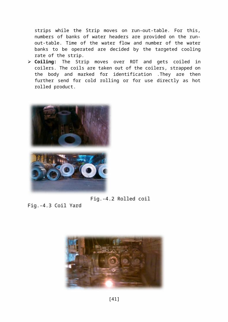
Coiling: The Strip moves over ROT and gets coiled in coilers. The coils are taken out of the coilers, strapped on the body and marked for identification .They are then further send for cold rolling or for use directly as hot rolled product.
[29]
Fig.-4.2 Rolled coil Fig.-4.3 Coil Yard
Fig.-4.4 Rolling Press
[30]
Chapter-05
CBRS
5.1 Introduction:The Central Base Repair Shop/CBRS comes under Works Division of Bokaro Steel Plant and it is responsible for major Repair, Renovation, and Reclamation of Heavy Earth Moving Equipment like (Haulpak-Dumpers, Dozers, Loaders, Excavators, and Cranes etc.). It has more than a hundred of such equipment in its fleet. These equipment are used for operation, maintenance and house-keeping jobs in different production areas like CO & BPP, RMHP, BF, SP, SMS, Mills etc.
5.2 The different sections of the CBRS are:- Engine Shop. Fabrication Shop. Machine Shop. Crane Section. Shovel Section. Dumper Section. Auto Electrical. Electrical. Transmission. Spare Planning.
As CBRS deals with mobile equipment its working area is very wide. We are the source to provide material handling, transports, cleaning, Expansion etc. to the production and non-production zones like Raw Material Handling Plant, Coke Oven, Blast furnace, Steel Melting Shops, CCS, Mills Zone,Auxiliary Zone and Township Areas etc. Network of the CBRS in Bokaro Steel Plant is as follows:
Coke Oven. Blast Furnace. Steel Melting Shops – I. Steel Melting Shops – II. Slabbing Mill. Hot Strip Mill. Foundries. Cold Rolling Mills. Housing Keeping Of Works Division. Sintering Plant.
[31]

Fig.-5.1 Network Of CBRS In BSL
Chapter-06
[32]
CBRSCokeBFSMS ISMS- IISlabbing MillHSMFoundariesCRMCCSHouse Keeping of work divisionCDISintering plantSlag
Engine Details/Specifications
6.1 Details of the engine, on which the project of my Summer Training was based, are given below:-
Table 6.1- Engine Specification
6.2 Major components of the engine are given below:-
[33]
Table 6.2-Components of Engine
[34]
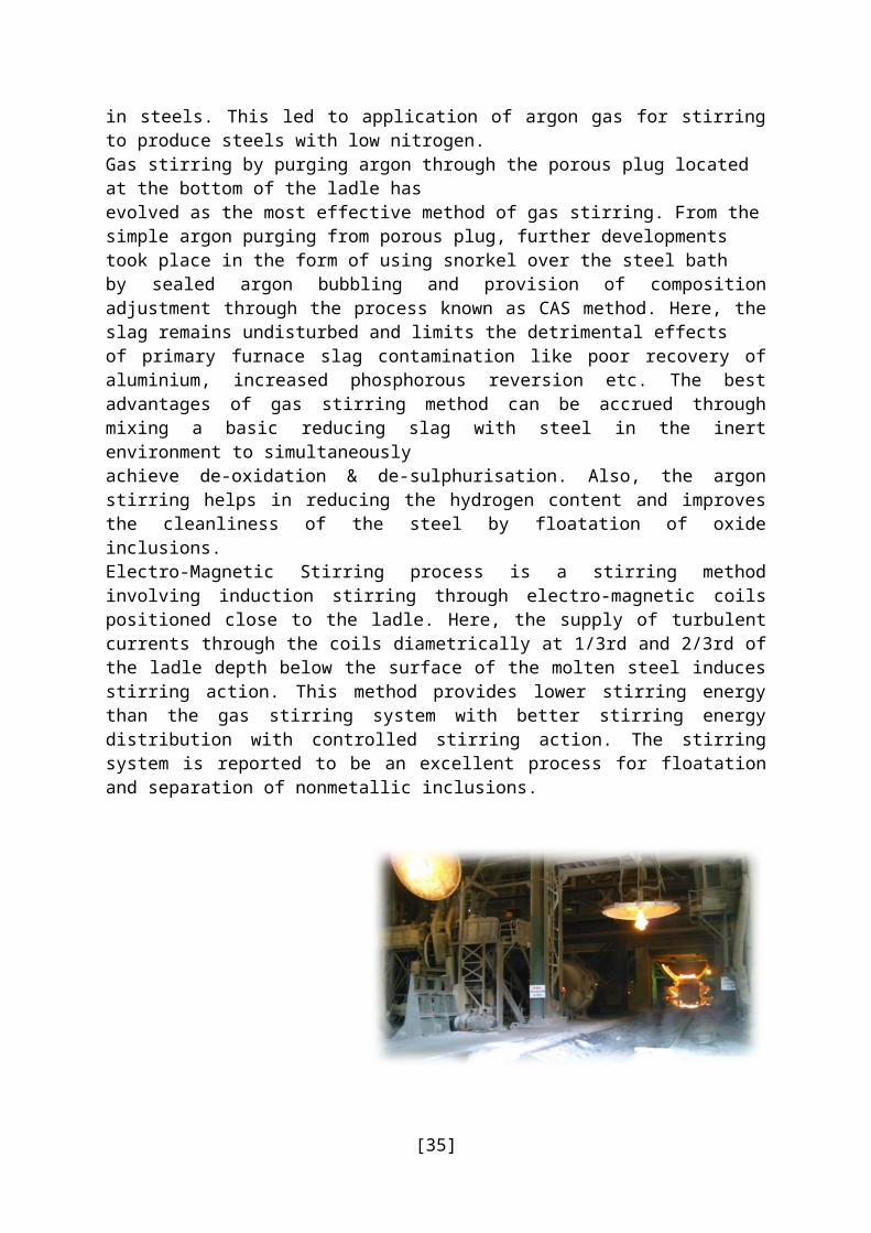
Fig.-6.1 CUMMINS KT-1150
6.3 Basic descriptions of some of the components of Engine KT-1150-C are given below:-
» Engine Block: An engine block is the core of the engine which houses nearly all of the components required for the engine to function properly. The block is typically arranged in a “V” inline, or 4 horizontally-opposed (also referred to as flat) configuration, and the number of cylinders range from either 3 to as much as 16. KT 1150 has 6 cylinder engine with inline configuration.
» Functional Requirement of a Cylinder Block: Because engine blocks are a critical component of an engine, it must satisfy a number of functional requirements. These requirements include lasting the life of the vehicle, housing internal moving parts and fluids, ease of service and maintenance, and withstand pressures created by the combustion process.
» Required Material Properties: In order for an engine block to meet the functional requirements listed above, the engineering material(s) used to manufacture the product must possess high strength, modulus of elasticity, abrasion resistance, and corrosion resistance. High strength is a particular concern in diesel engines, since compression ratios are normally 17.0:1 or higher (compared to about 10.0:1 forconventional engines). The material should also have a low density, thermal expansion (to resist expanding under high operating temperatures), and thermal conductivity (to prevent failure under high temperatures).
» Metals used in the manufacture of Cylinder Blocks: Based on the functional requirements of the cylinder block and the material properties required to meet the functional requirements, industries have used cast iron and aluminium alloys to manufacture the blocks. Cast iron alloys are used because of the combination of
[35]
good mechanical properties, low cost, and availability. Certain aluminium alloys combine the characteristics of iron alloys with low weight, thereby making the material more attractive to manufacturers who are seeking a competitive edge. Compacted graphite cast iron is lighter and stronger than grey cast iron, making the alloy a more attractive alternative to the latter in the production of cylinder blocks, particularly in diesel engines.
Engine Head Assembly: In an internal combustion engine, the cylinder head sits above the cylinders on top of the cylinder block. It closes in the top of the cylinder, forming the combustion chamber. This joint is sealed by a head gasket. In most engines, the head also provides space for the passages that feed air and fuel to the cylinder, and that allow the exhaust to escape. The head is also a place to mount the valves and fuel injectors. Correct positioning of the cylinder head is ensured by alignment of the water discharge elbow and it’s mating hole in the crankcase. The cylinder head is made of high strength cast iron alloy having special design cast passages for water and exhaust gases.
Crankshaft: The crankshaft is the part of an engine that translates reciprocating linear piston motion into rotation. To convert the reciprocating motion into rotation, the crankshaft has "crank throws" or "crankpins", additional bearing surfaces whose axis is offset from that of the crank, to which the "big ends" of the connecting rods from each cylinder attach. Large engines are usually multi-cylinder to reduce pulsations from individual firing strokes, with more than one piston attached to a complex crankshaft.
Bearings: The crankshaft has a linear axis about which it rotates, typically with several bearing journals riding on replaceable bearings (the main bearings) held in the engine block. As the crankshaft undergoes a great deal of sideways load from each cylinder in a multi-cylinder engine, it must be supported by several such bearings, not just one at each end. KT-1150-C is a six cylinder engine. One important thing to be mentioned here is that the no of main bearings is one more than the no of cylinders hence, KT-1150-C has 7 main bearings.
Vibration Damper: The function of vibration damper is to reduce the torsional vibration produced due to the firing in the cylinders. Following figure shows the vibration damper.
Connecting Rods: In a reciprocating piston engine, the connecting rod connects the piston to the crank or crankshaft. Together with the crank, they form a simple mechanism that converts reciprocating motion into rotating motion. The small end attaches to the piston pin, gudgeon pin or wrist pin, which is currently most often press fit into the connecting rod but can swivel in the piston, a "floating wrist pin" design. The big end connects to the bearing journal on the crank throw, in most engines running on replaceable bearing shells accessible via the connecting rod bolts which hold the bearing "cap" onto the big end. The connecting rod is under tremendous stress from the reciprocating load represented by the piston, actually stretching and being compressed with every rotation, and the load increases to the square of the engine speed increase.
Piston and Piston Rings:
[36]

Piston is the moving component that is contained by a cylinder and is made gas-tight by piston rings. In an engine, its purpose is to transfer force from expanding gas in the cylinder to the crankshaft via a piston rod and/or connecting rod. The three main functions of piston rings in reciprocating engines are–
» Sealing the combustion chamber so that there is no transfer of gases from the combustion chamber to the crank.
» Supporting heat transfer from the piston to the cylinder wall.» Regulating engine oil consumption.» There are four piston rings used in this engine namely ring compression top, ring
compression intermediate and two ring compression oil.
Camshaft: A camshaft is a shaft to which a cam is fastened or of which a cam forms an integral part.
» Uses - In internal combustion engines with pistons, the camshaft is used to operatepoppet valves. It then consists of a cylindrical rod running the length of the cylinderbank with a number of oblong lobes protruding from it, one for each valve. The camlobes force the valves open by pressing on the valve, or on some intermediatemechanism like cam follower and push rod as in case of KT-1150-C as they rotate.
» Timing - The relationship between the rotation of the camshaft and the rotation ofthe crankshaft is of critical importance. Since the valves control the flow of the air/fuel mixture intake and exhaust gases, they must be opened and closed at the appropriate time during the stroke of the piston. For this reason, camshaft is connected to the crankshaft either directly, via a gear mechanism, or indirectly via a belt or chain called a timing belt or timing chain. The timing of the camshaft can be advanced to produce better low RPM torque, or retarded for better high RPM power.
» Duration - Duration is the number of crankshaft degrees of engine rotation duringwhich the valve is off the seat. As a generality, greater duration results in more horse power. The RPM at which peak horsepower occurs is typically increased as duration increases at the expense of lower rpm efficiency (torque). A secondary effect of increase duration is increasing overlap, which is the number of crankshaft degrees during which both intake and exhaust valves are off their seats.
» Lift - The camshaft "lift" is the resultant net rise of the valve from its seat. The furtherthe valve rises from its seat the more airflow can be released, which is generally morebeneficial. Greater lift has some limitations. Firstly, the lift is limited by the increasedproximity of the valve head to the piston crown and secondly greater effort is requiredto move the valve's springs to higher state of compression. Increased lift can also belimited by lobe clearance in the cylinder head construction, so higher lobes may not necessarily clear the framework of the cylinder head casing. Higher valve lift can have the same effect as increased duration where valve overlap is less desirable.
» Position - Depending on the location of the camshaft, the cams operate the valveseither directly or through a linkage of pushrods and rockers. Direct operation involvesa simpler mechanism and leads to fewer failures, but requires the camshaft to bepositioned at the top of the cylinders.
[37]

» Maintenance - The rockers or cam followers sometimes incorporate a mechanism to adjust and set the valve play through manual adjustment. Sliding friction between the surface of the cam and the cam follower which rides upon it is considerable. In order to reduce wear at this point, the cam and follower are both surface hardened, and modern lubricant motor oils contain additives specifically to reduce sliding friction.The lobes of the camshaft are usually slightly tapered, causing the cam followers or valve lifters to rotate slightly with each depression, and helping to distribute wear on the parts. The surfaces of the cam and follower are designed to "wear in" together, and therefore when either is replaced, the other should be as well to prevent excessive rapid wear.
Manifold: Inlet manifold or intake manifold is the part of an engine that supplies the fuel/air mixture to the cylinders. In contrast, an exhaust manifold collects the exhaust gases from multiple cylinders into one pipe. The primary function of the intake manifold is to evenly distribute the combustion mixture (or just air in a direct injection engine) to each intake port in the cylinder head(s). Even distribution is important to optimize the efficiency and performance of the engine. The design and orientation of the intake manifold is a major factor in the volumetric efficiency of an engine. Abrupt contour changes provoke pressure drops, resulting in less air entering combustion chamber; high-performance manifolds have smooth contours and gradual transitions between adjacent segments.
Cam Follower: A cam follower is a special component which follows cam. It transmits the motion provided from camshaft to the push rods. It is an intermediate mechanism to open valves. The figure below shows the cam follower used in KT-1150-C engine. There were six cam followers used in the engine.
Push Rods: Push rods act as a link between cam follower and rocker arms. Three push rods per cylinder head are used in the engine for opening inlet and exhaust valves. One push rod is used for fuel injector.
The following parts shows the push rods being used in the engine.
Rocker Arms and Housing: Rocker arms finally transmit the motion provided by the camshaft via cam follower and push rods to the valves and fuel injector. Rocker housing rests these rocker arms.
Fuel Injector: Fuel injector is a device for admitting fuel into an internal combustion engine. It has become the primary fuel delivery system used in automotive engines, having replaced carburetors during the 1980s and 1990s. A variety of injection systems have existed since the earliest usage of the internal combustion engine. The primary difference between carburetors and
fuel injector system is that fuel injection atomizes the fuel by forcibly pumping it through a small nozzle under high pressure, while a carburetor relies on suction created by intake air accelerated through a Venturi tube to draw the fuel into the airstream.
[38]

The following figure shows the fuel injector used in KT-1150-C engine. There are six fuel injectors used, one for each cylinder.
Water Pump: It circulates water throughout the engine body for cooling. CAC (coolant additive concentrate) is also mixed with water to prevent engine from corrosion. Following figure shows the water pump being mounted in the engine.
Fuel Pump: The function of fuel pump in an internal combustion engine is to withdraw fuel (diesel in this case) from fuel tank and to deliver it to fuel injectors.
Lubricating Oil Cooler: There are two lube oil coolers used in the Cummins KT-1150-C engine.The function of cooler is to cool the lube oil. Water is used as a cooling agent.
Thermostat: It allows the proper cooling of the engine. It holds the water in the cylinder liner and does not allow it to pass through it until the temperature reaches 95˚C. After this temperature water is allowed to go to the radiator for cooling.
Turbocharger: Turbocharger is used for increasing engine performance. It sucks the air and delivers to intake manifold. One advantage of turbocharger is that it is powered by exhaust gases from the engine. Thus exhaust gases can be used to run the impeller of turbocharger which is connected to another impeller which sucks air.
Flywheel: A flywheel is a rotating mechanical device that is used to store rotational energy.Flywheels have a significant moment of inertia and thus resist changes in rotational speed.The amount of energy stored in a flywheel is proportional to the square of its rotational speed. Energy is transferred to a flywheel by applying torque to it, thereby increasing its rotational speed, and hence its stored energy. Three common uses of a flywheel include –
» They provide continuous energy when the energy source is discontinuous. For example, flywheels are used in reciprocating engines because the energy source, torque from the engine, is intermittent.
» They deliver energy at rates beyond the ability of a continuous energy source. This isachieved by collecting energy in the flywheel over time and then releasing the energyquickly, at rates that exceed the abilities of the energy source.
» They control the orientation of a mechanical system. In such applications, the angularmomentum of a flywheel is purposely transferred to a load when energy is transferredto or from the flywheel.
[39]

Fig.-6.2 Exploded View Of Engine
[40]
6.4 Engine Overhauling:Engine Overhauling is an adjustment, modification of the internal combustion engine or modification to its control unit, otherwise known as its ECU (Engine Control Unit). It is performed to yield optimal performance, to increase an engine's power output, economy, or durability. These goals may be mutually exclusive, and an engine may be detuned with respect to output (work) in exchange for better economy or longer engine life due to lessened stress on engine components. The engine is removed from the vehicle and totally stripped down - every nut and bolt is removed, cleaned, checked.Most moving parts are replaced with brand new factory stock parts - often the only original parts of an engine that has been moved are the block casting, the head casting, the crankshaft, flywheel and camshaft. If any of those aren't in serviceable condition they get switched out too and the motor gets a fresh paint job.Overhauling, a general term for major engine work that usually requires removing the engine from the vehicle, and rebuilding or replacing internal components (e.g. pistons, connecting rods, valves).The amount of parts that are replaced depends on the condition of all internal parts. Overhauling is usually done when engine parts get damaged and don’t perform the required functions arising serious problems like low power output, engine overheating, starting problem, etc. To save engine parts from getting damaged, regular maintenance and repair should be done after certain period of time. So,maintenance, repair and overhauling can be summed up as all the actions required retaining or restoring an item in a state in which it can perform it required function.
6.4.1 Some basic tips for keeping an engine in good condition are as follows:-
Keeping dirt out of the engine. Maintaining a lubricating film on all bearing surfaces. Regulating the engines fuel. Controlling operating temperatures. Guarding against corrosion. Letting the engine breathe. Preventing over speeding. Knowing the engine’s condition. Correcting troubles while they are still simple. Scheduling and controlling its maintenance.
Most failures give an early warning. Looking and listening for changes in performance, sound or engine appearance that can indicate the need for servicing or repairing is important. Some such changes to look for are as follows:-
Engine misfires. Vibration. Unusual engine noises. Sudden changes in engine operating temperature or pressure. Excessive smoke. Loss of power. An increase in oil consumption. An increase in fuel consumption. Fuel, oil or coolant leaks.
6.4.2 The process of Engine Overhauling consists of several types of maintenance checks. They are as follows:-
[41]

1. “A” Maintenance Checks» Daily» Weekly
2. “B” Maintenance Checks (300 hours/6 months)» 1500 hours Maintenance Checks» First 1500 hours Maintenance Checks
3. “C” Maintenance Checks (1500 hours/1 year)
4. “D” Maintenance Checks (6000 hours/2 years)o Seasonal Maintenance Checks
CONCLUSION
[42]

After the completion of Industrial Training we enhanced competencies and competitiveness
in our respective area of specialization. We need to relate the experience in the workplace
with knowledge learned in the institute and applied the knowledge on the job under
supervision.
Here, we gained knowledge and experience that can be used for suitable job without delay
after studies. We learned to hone soft skills appropriate to the work environment. We have
also got improvised in communication skills. We assessed career ability, knowledge and
confidence as well as enhanced our marketability to be more competitive
Undergoing Training on the indoor departments has helped me integrate conceptual
knowledge with real life application. I am fortunate to have personal guidance from
Experienced Professionals, who took keen interest in explaining the working details of
various department.
“To know the Technical know-how, Industrial Training is the best way to move Forward.”
REFERENCES
[43]

www.sail.com
www.google.com
www.wikipedia.com
[44]