Training Material on Anaerobic Wastewater Treatment Ecosan ...
46
Training Material on Anaerobic Wastewater Treatment Version 3, December 16 th , 2008 [email protected] Training Material on Anaerobic Wastewater Treatment Version 3, December 16 th , 2008 Ecosan Expert Training Course “Capacity Building for Ecological Sanitation in Bhutan” Compiled by Dipl. Ing. Martin Wafler, seecon gmbh
Transcript of Training Material on Anaerobic Wastewater Treatment Ecosan ...

Training Material on Anaerobic Wastewater Treatment Version 3, December 16th, 2008
Training Material on Anaerobic Wastewater Treatment
Version 3, December 16th, 2008
Ecosan Expert Training Course
“Capacity Building for Ecological Sanitation in Bhutan”
Compiled by Dipl. Ing. Martin Wafler, seecon gmbh

Training Material on Anaerobic Wastewater Treatment Version 3, December 16th, 2008
Permission is granted for reproduction of this training material, in whole or part, for eductation, scientific or development related purposes except those involving commercial sale.
seecon gmbh Bahnhofstrasse 2 6110 Wolhusen, Switzerland Phone: +41-79-3666850 Email: [email protected] Web: http://www.seecon.ch
Ecosan Services Foundation (ESF) "Vishwa Chandra" 1002/42 Rajendra Nagar Pune – 411030, Maharashtra, India Phone/Fax: +91-(0)20-64000736 Email: [email protected] Web: http://www.ecosanservices.org

Training Material on Anaerobic Wastewater Treatment Version 3, December 16th, 2008
LIST OF CONTENT
LIST OF FIGURES....................................................................................................V
LIST OF TABLES .....................................................................................................V
1 INTRODUCTION TO ANAEROBIC WASTEWATER TREATMENT .............1
1.1 Biogas definition .................................................................................................... 1 1.2 Composition and properties of biogas................................................................. 1
1.3 How is it produced (the three steps of biogas production)................................ 2 1.3.1 Hydrolysis and fermentation..................................................................................... 2 1.3.2 Acidification .............................................................................................................. 2 1.3.3 Methane formation ................................................................................................... 3 1.3.4 Symbiosis of bacteria ............................................................................................... 3
1.4 Description of various anaerobic treatment systems......................................... 3 1.4.1 Biogas plants............................................................................................................ 4 1.4.1.1 Balloon digester.......................................................................................................................................... 4 1.4.1.2 Floating-drum digester ............................................................................................................................... 5 1.4.1.3 Fixed-dome digester .................................................................................................................................. 7 1.4.2 Anaerobic (pre)treatment plants............................................................................... 7 1.4.2.1 Biogas settler .............................................................................................................................................. 8 1.4.2.2 Anaerobic Baffled Reactor (ABR) ............................................................................................................. 9 1.4.2.3 Upflow Anaerobic Sludge Blanket (UASB) Reactor .............................................................................. 10 1.4.2.4 Anaerobic Lagoons (with biogas recovery) ............................................................................................ 12 1.5 Minimizing greenhouse gas emission potentials.............................................. 13
2 SAMPLE DESIGN PROBLEM „TOILET-LINKED BIOGAS PLANTS“.......14
2.1 Properties of different feed materials................................................................. 15
2.2 Biogas demand vs. anticipated biogas yield ..................................................... 15 2.3 Scaling of gasholder............................................................................................ 18
2.4 Scaling of digester ............................................................................................... 20 2.4.1 Estimation of feed material production and calculation of digester volume ............ 20 2.4.2 Scaling of floating-drum type biogas plant.............................................................. 22 2.4.3 Scaling of fixed-dome type biogas plant................................................................. 23
2.5 Slurry collection, treatment and application...................................................... 27 2.5.1 Direct application of the slurry................................................................................ 27 2.5.2 Advanced treatment of slurry in sludge drying beds............................................... 27

Training Material on Anaerobic Wastewater Treatment Version 3, December 16th, 2008
3 SAMPLE DESIGN PROBLEM „PRE-TREATMENT OF WASTEWATER IN A BIOGAS SETTLER“ .................................................................................28
3.1 Domestic wastewater quantification and characterisation .............................. 28 3.2 Sizing of biogas settler........................................................................................ 30 3.2.1 Post-treatment for biogas settler effluent................................................................ 33
4 BIBLIOGRAPHY...........................................................................................34
5 SKETCHES, TECHNICAL DRAWINGS.......................................................35

Training Material on Anaerobic Wastewater Treatment Version 3, December 16th, 2008
LIST OF FIGURES
figure 1: Anaerobic digestion pathway...........................................................................2
figure 2: Conceptual sketches of balloon-type digesters ...............................................4
figure 3: Conceptual sketches of floating-drum type digesters ......................................5
figure 4: Conceptual sketches of fixed-dome type digesters..........................................6
figure 5: Cut-away view of anaerobic baffled reactor.....................................................9
figure 6: Anaerobic lagoon with recovery of biogas .....................................................10
figure 7: Anaerobic lagoon with recovery of biogas .....................................................11
figure 8: Distinct volumes to be considered while calculating net volume of biogas plant.......................................................................................................................23
figure 9: Various important levels of fixed-dome biogas plants....................................23
figure 10: Conceptual sketch of compensation tank (above the overflow level radius RCT is reduced by 1.5 cm per course of bricks) ....................................................25
figure 11: Calculation of net volume of compensation tank ...........................................25
figure 12: Calculation of “P-line” ....................................................................................26
figure 13: View of simple sludge drying beds.................................................................27
figure 14: Conceptual sketch of toilet-linked biogas unit................................................36
figure 15: Construction of biogas settler (clockwise from top left: excavated pit for biogas settler; a first layer of P.C.C. has been poured directly on the ground; the foundation of the biogas settler is made from P.C.C.; the first brick is laid using a “radius stick”) ..............................................................................................37
figure 16: Construction of biogas settler (detail “radius stick”; the outside of the wall is sealed with cement mortar; biogas settler and compensation tank; fixing and sealing of lid) .................................................................................................38
LIST OF TABLES
table 1: Advantages and limitations of balloon digesters..............................................4
table 2: Advantages and limitations of floating-drum type digesters.............................6

Training Material on Anaerobic Wastewater Treatment Version 3, December 16th, 2008
table 3: Advantages and limitations of fixed-dome type digesters................................7
table 4: Advantages and limitations of on-site treatment of wastewater in biogas settlers .............................................................................................................8
table 5: Advantages and limitations of anaerobic baffled reactors................................9
table 6: Advantages and limitations of UASB reactors ...............................................11
table 7: Advantages and limitations of anaerobic lagoons..........................................12
table 8: Advantages and limitations of on-site treatment of toilet water in biogas plants.......................................................................................................................14
table 9: Properties of different feed materials.............................................................15
table 10: Specific biogas consumption of various appliances.......................................16
table 11: Common substrate mixing ratios ...................................................................21
table 12: Common dimensions of floating-drum type biogas plants .............................22
table 13: Domestic wastewater characteristics (excerpt)..............................................28
table 14: Break up of water requirements for domestic purposes according to CPHEEO „Manual on Water Supply and Treatment“.....................................................29

Training Material on Anaerobic Wastewater Treatment Version 3, December 16th, 2008
DISCLAIMER
The use of these training materials is open to everyone. However, the responsibility for correct application lies with the user and respective legal or administrative regulations have to be followed. This applies in particular for the choice of the application rates and design parameters described in this training material, which should only be regarded as a rough 'guideline' and not as a manual. The materials might be a helpful but not the only source of information for correct application of concepts and technologies described.
Mentioning of any product, company, supplier, etc. in this training material does not express any preference of one or the other product, company, supplier, etc. to another, which may not be mentioned in this training material, but is of indicative purpose only.

Training Material on Anaerobic Wastewater Treatment Version 3, December 16th, 2008
1
1 INTRODUCTION TO ANAEROBIC WASTEWATER TREATMENT
1.1 Biogas definition
Biogas originates from bacteria in the process of bio-degradation of organic material under anaerobic (without air) conditions. The natural generation of biogas is an important part of the biogeochemical carbon cycle. Methanogens (methane producing bacteria) are the last link in a chain of microorganisms, which degrade organic material and return the decomposition products to the environment. In this process biogas is generated, a source of renewable energy [1].
1.2 Composition and properties of biogas
Biogas is a mixture of gases that is composed chiefly of:
• methane (CH4): 40 - 70 vol.%
• carbon dioxide (CO2): 30 - 60 vol.%
• other gases: 1 - 5 vol.%
including:
• hydrogen (H2): 0 - 1 vol.%
• hydrogen sulfide (H2S): 0 - 3 vol.%
Like those of any pure gas, the characteristic properties of biogas are pressure and temperature-dependent. They are also affected by the moisture content. The factors of main interest are:
• change in volume as a function of temperature and pressure,
• change in calorific value as a function of temperature, pressure and water-vapor content, and
• change in water-vapor content as a function of temperature and pressure.
Biogas is used as an ecologically friendly and future oriented technology in many countries. The calorific value of biogas is about 6 kWh/m3 - this corresponds to about half a litre of diesel oil. The net calorific value depends on the efficiency of the burners or appliances. Methane is the valuable component under the aspect of using biogas as a fuel [1].

Training Material on Anaerobic Wastewater Treatment Version 3, December 16th, 2008
2
1.3 How is it produced (the three steps of biogas production)
The general model for degradation of organic material under anaerobic conditions operates principally with three main groups of bacteria: fermenting, acetogenic and methanogenic bacteria, which degrade organic mater in four stages viz., hydrolysis, fermentation, acidification and methane formation (see figure 1).
1.3.1 Hydrolysis and fermentation
In the first step (hydrolisis), the organic matter is enzymolyzed externally by extracellular enzymes (cellulase, amylase, protease and lipase) of microorganisms. Bacteria decompose the long chains of the complex carbohydrates, proteins and lipids into shorter parts. For example, polysaccharides are converted into monosaccharides. Proteins are split into peptides and amino acids [1].
1.3.2 Acidification
Acid-producing bacteria, involved in the second step, convert the intermediates of fermenting bacteria into acetic acid (CH3COOH), hydrogen (H2) and carbon dioxide (CO2).
(source: [2])
figure 1: Anaerobic digestion pathway

Training Material on Anaerobic Wastewater Treatment Version 3, December 16th, 2008
3
These bacteria are facultatively anaerobic and can grow under acid conditions. To produce acetic acid, they need oxygen and carbon. For this, they use the oxygen solved in the solution or bound oxygen. Hereby, the acid-producing bacteria create an anaerobic condition, which is essential for the methane-producing microorganisms. Moreover, they reduce the compounds with a low molecular weight into alcohols, organic acids, amino acids, carbon dioxide, hydrogen sulphide and traces of methane. From a chemical standpoint, this process is partially endergonic (i.e. only possible with energy input), since bacteria alone are not capable of sustaining that type of reaction [1].
1.3.3 Methane formation
Methane-producing bacteria, involved in the third step, decompose compounds with a low molecular weight. For example, they utilize hydrogen, carbon dioxide and acetic acid to form methane and carbon dioxide. Under natural conditions, methane producing microorganisms occur to the extent that anaerobic conditions are provided, e.g. under water (for exemple in marine sediments), in ruminant stomaches and in marshes. They are obligatory anaerobic and very sensitive to environmental changes [1].
1.3.4 Symbiosis of bacteria
Methane- and acid-producing bacteria act in a symbiotical way. On the one hand, acidproducing bacteria create an atmosphere with ideal parameters for methane-producing bacteria (anaerobic conditions, compounds with a low molecular weight). On the other hand, methane-producing microorganisms use the intermediates of the acid-producing bacteria. Without consuming them, toxic conditions for the acid-producing microorganisms would develop.
In practical fermentation processes the metabolic actions of various bacteria all act in concert. No single bacterium is able to produce fermentation products alone [1].
1.4 Description of various anaerobic treatment systems
Anaerobic treatment systems are widely used for the digestion of animal manure, wet organic waste, blackwater (i.e. toilet water), high-strength greywater, domestic wastewater and the co-treatment of various of the above mentioned substrates.
The design of the anaerobic treatment system varies according to the feed material, the solid content and the desired degree of treatment.

Training Material on Anaerobic Wastewater Treatment Version 3, December 16th, 2008
4
1.4.1 Biogas plants
Simple biogas plants such as balloon digesters, floating-drum digesters and fixed-dome digesters use animal manure, organic waste and/or nightsoil as a substrate for the recovery of biogas to be used as a substitute to LPG in cooking and lighting.
1.4.1.1 Balloon digester
The balloon plant (figure 2, left hand side) consists of a digester bag (e.g. PVC) in the upper part of which the gas is stored. The inlet and outlet are attached directly to the plastic skin of the balloon. The gas pressure is achieved through the elasticity of the balloon and by added weights placed on the balloon. A variation of the balloon plant is the channel-type digester, which is usually covered with plastic sheeting and a sunshade (figure 2, right hand side). Balloon plants can be recommended wherever the balloon skin is not likely to be damaged and where the temperature is even and high [1].
Advantages and limitations of balloon digesters are summarized in table 1.
(source: [1])
figure 2: Conceptual sketches of balloon-type digesters
table 1: Advantages and limitations of balloon digesters
Advantages: Limitations: • low cost; • relatively short life (about five years);
• ease of transportation; • susceptibility to damage;
• low construction sophistication; • little creation of local employment;

Training Material on Anaerobic Wastewater Treatment Version 3, December 16th, 2008
5
1.4.1.2 Floating-drum digester
Floating-drum plants consist of an underground digester and a moving gasholder. The gasholder floats either directly on the fermentation slurry (figure 3, left hand side) or in a water jacket of its own (figure 3, right hand side). The gas is collected in the gas drum, which rises or moves down, according to the amount of gas stored. The gas drum is prevented from tilting by a guiding frame [1]. Water-jacket digesters are universally applicable and especially easy to maintain. The drum won't stick, even if the substrate has a high solids content. Floating-drums made of glass-fibre reinforced plastic and high-density polyethylene have been used successfully, but the construction cost is higher than for its steel counterpart. Floating-drums made of wire-mesh-reinforced concrete are liable to hairline cracking and are intrinsically porous. They require a gastight, elastic internal coating. PVC drums are unsuitable because they are not resistant to UV radiation [3].
• high digester temperatures; • limited self-help potential;
• uncomplicated cleaning, emptying and maintenance;
• little knowledge for repairing by local craftsmen [3]
(source: [1])
(source: [1])
figure 3: Conceptual sketches of floating-drum type digesters

Training Material on Anaerobic Wastewater Treatment Version 3, December 16th, 2008
6
Advantages and limitations of floating-drum type digesters are summarized in table 2.
table 2: Advantages and limitations of floating-drum type digesters
Advantages: Limitations: • simple, easily understood operation; • high material costs of the steel drum;
• the volume of stored gas is directly visible;
• susceptibility of steel parts to corrosion (because of this, floating drum plants have a shorter life span than fixed-dome plants);
• the gas pressure is constant (determined by the weight of the gas holder);
• regular maintenance costs for the painting of the drum
• construction is relatively easy; • if fibrous substrates are used, the gasholder shows a tendency to get "stuck" in the resultant floating scum [3];
• construction mistakes do not lead to major problems in operation and gas yield;
(source: [1])
(source: [1])
figure 4: Conceptual sketches of fixed-dome type digesters
Training Material on Anaerobic Wastewater Treatment Version 3, December 16th, 2008
7
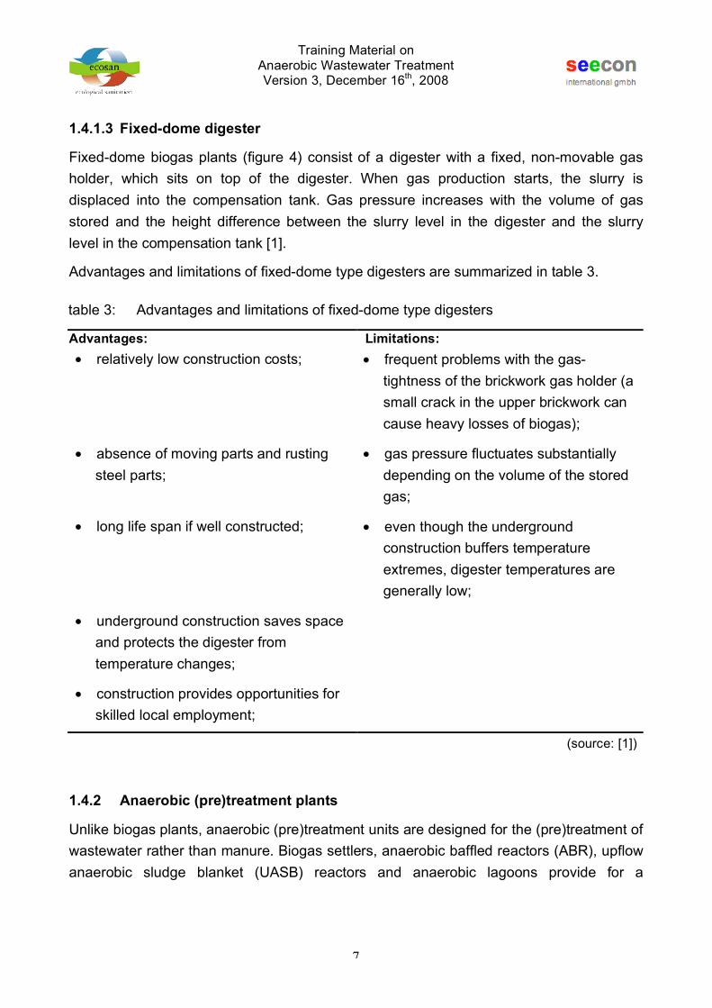
1.4.1.3 Fixed-dome digester
Fixed-dome biogas plants (figure 4) consist of a digester with a fixed, non-movable gas holder, which sits on top of the digester. When gas production starts, the slurry is displaced into the compensation tank. Gas pressure increases with the volume of gas stored and the height difference between the slurry level in the digester and the slurry level in the compensation tank [1].
Advantages and limitations of fixed-dome type digesters are summarized in table 3.
1.4.2 Anaerobic (pre)treatment plants
Unlike biogas plants, anaerobic (pre)treatment units are designed for the (pre)treatment of wastewater rather than manure. Biogas settlers, anaerobic baffled reactors (ABR), upflow anaerobic sludge blanket (UASB) reactors and anaerobic lagoons provide for a
table 3: Advantages and limitations of fixed-dome type digesters
Advantages: Limitations: • relatively low construction costs; • frequent problems with the gas-
tightness of the brickwork gas holder (a small crack in the upper brickwork can cause heavy losses of biogas);
• absence of moving parts and rusting steel parts;
• gas pressure fluctuates substantially depending on the volume of the stored gas;
• long life span if well constructed; • even though the underground construction buffers temperature extremes, digester temperatures are generally low;
• underground construction saves space and protects the digester from temperature changes;
• construction provides opportunities for skilled local employment;
(source: [1])

Training Material on Anaerobic Wastewater Treatment Version 3, December 16th, 2008
8
comparatively short hydraulic retention time (HRT) but and increased solid retention time (SRT).
1.4.2.1 Biogas settler
Similar in construction to fixed-dome biogas plants, biogas settlers (sometimes also refered to as “Biodigester Septic Tanks” or “UASB Septic Tanks”) have been introduced as cost-effective pre-treatment or treatment step for domestic wastewater or blackwater in countries such as Jaimaca [4], South Africa [5], China [6] and India [7] by various organisations.
Biogas settler are designed to:
• facilitate solid-liquid separation;
• provide a high sludge retention time, that facilitates almost complete degradation of organics;
• enable production and collection of biogas for direct use (e.g. lighting, cooking, etc.).
Depending upon the hydraulic retention time (HRT) a biogas settler may be considered a pre-treatment or treatment unit. Biogas settlers that are designed for pre-treatment of domestic wastewater (combined greywater and blackwater) provide a HRT of 24 hours or less [8]; subsequent treatment of the effluent in an anaerobic baffle reactor and constructed wetland system may be required. With an increased HRT (8 to 10 days and ca. 15 days with and without urine-separation, respectively) anaerobic treatment of the liquid phase happens and advanced treatment of the effluent may be done in a constructed wetland system only [6].
Advantages and limitations of on-site pre-treatment of wastewater in biogas settlers are summarized in table 4.
table 4: Advantages and limitations of on-site treatment of wastewater in biogas settlers
Advantages: Limitations: • no handling of raw (unprocessed)
wastewater; • gas pressure fluctuates substantially
depending on the volume of the stored gas;
• biogas may be used as a substitute to LPG in cooking;

Training Material on Anaerobic Wastewater Treatment Version 3, December 16th, 2008
9
1.4.2.2 Anaerobic Baffled Reactor (ABR)
In anaerobic baffled reactors (ABRs), a number of mechanical and anaerobic cleansing processes are applied in sequence. The reactor consists of different chambers (connected in series) in which the wastewater flows up-stream. On the bottom of each chamber activated sludge is located. During inflow into the chamber wastewater is intensively mixed up with the sludge and wastewater pollutants are decomposed. In the first chambers the easily degradable substances are removed. In the following chambers, substances, which are less easily biodegradeable, are removed. The more chambers are applied the higher the performance. The design shown below includes an integrated sedimentation chamber for pre-treatment [9].
Advantagese and limitations of anaerobic baffled reactors are summarized in table 5.
(source: [9])
figure 5: Cut-away view of anaerobic baffled reactor
table 5: Advantages and limitations of anaerobic baffled reactors
Advantages: Limitations: • Suitable for small & large settlements; • Experts required for design and
supervision ;
• Little space required due to underground construction;
• Master mason required for high-quality plastering work;

Training Material on Anaerobic Wastewater Treatment Version 3, December 16th, 2008
10
1.4.2.3 Upflow Anaerobic Sludge Blanket (UASB) Reactor
Upflow anaerobic sludge blanket reactors consist of a deep tank in which wastewater pours near the bottom and is equally distributed over its total area. In the lower part of the reactor, a sludge blanket is maintained through which the wastewater is forced to
• Low investment costs; • Infectious organisms are not sufficiently removed
• Very low operation and maintenance costs;
• Well-organized CBO or service provider needed for operation and maintenance
• Standardised designs and standard operation procedures available;
• Manual de-sludging of the tank is highly hazardous and an inhumane task
• Simple operation and maintenance; • Mechanical de-sludging (vacuum trucks) requires sophisticated instruments
• High treatment efficiency
(source: adapted from [9])
(source: [9])
figure 6: Anaerobic lagoon with recovery of biogas

Training Material on Anaerobic Wastewater Treatment Version 3, December 16th, 2008
11
percolate upwards. This results in sedimentation and absorption of organic waste matter and biological conversion to biogas. This gas forms bubbles that escape from the blanket providing the necessary mixing of the sludge mass. In the upper part of the tank, treated wastewater is separated from sludge and biogas in specific gas-liquid-solids separators (GLSS). Excess sludge is removed once every few years [9].
Advantagese and limitations of UASB reactors are summarized in table 6.
table 6: Advantages and limitations of UASB reactors
Advantages: Limitations: • Relatively low investment and
maintenance costs; • Low community contribution for
construction work;
• Little space required due to underground construction;
• Technical energy and feeder pump required;
• High potential treatment efficiency; • Stable fluidised bed difficult to maintain;
• System can be upgraded • Not resistant against shock-loads;
• Operation difficult for fluctuating inflows;
• De-sludging procedures require professional service provider;
(source: adapted from [9])
(photo: H.P. Mang)
figure 7: Anaerobic lagoon with recovery of biogas

Training Material on Anaerobic Wastewater Treatment Version 3, December 16th, 2008
12
1.4.2.4 Anaerobic Lagoons (with biogas recovery)
Anaerobic lagoons are extremely simple in construction, operation and maintenance. Decomposition processes are similar to the process in nature. The pond is made of 2,5 – 5 m deep earthen basin with an embankment slope of 1:3. Detention time of influent is about 20 – 30 days. An area of 1 - 3 m² is required for treatment of wastewater generated by one person. Dependent on the load, anaerobic ponds must be de-sludged regularly. It is quite common to use pond systems in series of two or three modules for a full scale treatment [9].
Advantages and limitations of anaerobic lagoons are summarized in table 7.
table 7: Advantages and limitations of anaerobic lagoons
Advantages: Limitations: • Low-cost system suitable for rural and
semi-urban communities; • Only applicable where land is available
and cheap;
• High community participation in construction and O & M possible;
• Permanent overload leads to breakdown of biological cleansing processes;
• Simple operation & maintenance; • Misuse of system leads to public health hazard;
• Resistant against shock load and variable inflow volume, if lagoon size is big enough;
• Sullage is in the open and thus poses a potential health threat;
• Low treatment efficiency, effluent is still infectious;
• Not suitable where there is a high groundwater table due to infiltration of sullage;
• Public health hazard if system if overloaded;
(source: adapted from [9])

Training Material on Anaerobic Wastewater Treatment Version 3, December 16th, 2008
13
1.5 Minimizing greenhouse gas emission potentials
Green house gas emissions from biogas plants and commonly applied anaerobic on-site wastewater treatment systems such as septic tanks, baffled reactors, etc. are usually considered as negligible. But, every anaerobic wastewater treatment plant, independent of its size, constitutes to the global warming potential if it is not properly designed, built, operated and maintained and if it is either not equipped with a gas cover or the gas is simply released to the atmosphere without flaring after collection.
With anaerobic, reuse-oriented wastewater management schemes getting more and more popular, it is therefore of paramount importance not only to provide for their cultural, social and economic sustainability, but also focus on the environmental sustainability with particular regard to green house gas emissions and climate issues.
Green house gas emission potentials from anaerobic on-site wastewater treatment units can be minimized by applying best practice in:
• awareness raising (with specific regard to green house gas emission potential of commonly applied anaerobic on-site or semi-decentralized wastewater treatment units);
• the state-of-the-art designing of wastewater management schemes for anaerobic (pre)-treatment of domestic wastewater and the recovery of biogas;
• the promotion of use of biogas as a substitute to LPG and/or fuel wood;
• the on-the-job-training and supervision of operation and maintenance of small to medium-size anaerobic wastewater treatment units.

Training Material on Anaerobic Wastewater Treatment Version 3, December 16th, 2008
14
2 SAMPLE DESIGN PROBLEM „TOILET-LINKED BIOGAS PLANTS“
Night-soil based or toilet-linked biogas plants (figure 14) are widely used in Asia for the co-digestion of human excreta along with animal manure (e.g. cattle or buffalo dung, etc.) or the hygienically safe on-site treatment of toilet water and recovery of valuable energy in the form of biogas to be used as a substitute to LPG (Liquefied Petroleum Gas) in cooking and lighting.
The centre part of a sanitary biogas unit is the bio-digester (i.e. either a floating-drum or fixed-dome type biogas plant) that receives the animal manure and/or toilet water from pour-flush toilets and degrades the organics (animal manure, excreta, etc.) anaerobically, thus producing biogas and a slurry that can be utilised as soil amendment after advanced treatment in sludge drying beds. As biogas production from human excreta only is limited (ca. 40 litres per person per day), the main focus is however mostly on sanitary aspects, i.e. clean toilets with low maintenance demand, rather than a high gas productivity.
Advantages and Limitations of toilet-linked biogas plants are summarized in table 8.
table 8: Advantages and limitations of on-site treatment of toilet water in biogas plants
Advantages: Limitations: • no handling of raw (unprocessed) toilet
water; • limited biogas production if only toilet
water is treated;
• increased biogas production if additional feed material (e.g. animal manure, etc.) is available for co-digestion;
• biogas may be used as a substitute to LPG in cooking
• application of digested slurry as soil amendment to agricultural plots possible

Training Material on Anaerobic Wastewater Treatment Version 3, December 16th, 2008
15
2.1 Properties of different feed materials
Most simple biogas plants are "fueled" with manure (dung and urine), because such substrates usually ferment well and produce good biogas yields [10].
It is difficult to offer approximate excrement-yield values, because they are subject to wide variation. In the case of cattle, for example, the yield can amount to anywhere from 8 to 40 kg per head and day, depending on the strain in question and the housing intensity. Manure yields should therefore be either measured or calculated on a liveweight basis, since there is relatively good correlation between the two methods. The quantities of manure listed in table 9 are only then fully available, if all of the animals are kept in stables all of the time and if the stables are designed for catching urine as well as dung. Thus, the stated values will be in need of correction in most cases. If cattle are kept in night stables, only about 1/3 to 1/2 as much manure can be collected. For cattle stalls with litter, the total yields will include 2 - 3 kg litter per animal and day [10].
2.2 Biogas demand vs. anticipated biogas yield
The biogas demand may be estimated by way of appliance consumption data and assumed periods of use, but this approach can only work to the extent that the appliances
table 9: Properties of different feed materials
daily manure yield fresh-
manure solids
gas yield
manure urine DM ODM
liveweight C/N
range average
animal species/
feed material
[kg/d] [%lw] [%lw] [%] [%] [kg] [-] [l/kg ODM] cattle
manure 8 5 4 - 5 16 13 135 - 800 10 - 25 150 - 350 250
buffalo manure 12 5 4 - 5 14 12 340 - 420 20
pig manure 2 2 3 16 12 30 - 75 9 - 13 340 - 550 450 sheep/goat droppings 1 3 1 - 2 30 20 30 - 100 30 100 - 310 200
chicken manure 0.08 4.5 - 25 17 1.5 - 2 5 - 8 310 - 620 460
human excreta 0.5 1 2 20 15 50 - 80 8
corn straw - - - 80 73 - 30 - 65 350 - 480 410 water
hyacinths - - - 7 5 - 20 - 30 300 - 350 325
vegetable residues - - - 12 10 - 35 300 - 400 350
fresh grass - - - 24 21 - 12 280 - 550 410 (source: ÖKOTOP in [10], [11])

Training Material on Anaerobic Wastewater Treatment Version 3, December 16th, 2008
16
to be used are known in advance (e.g. a biogas lamp with a specific gas consumption of 120 liter per hour and a planned operating period of 3 hours per day, resulting in a gas demand of 360 liter per day) [10].
Specific biogas consumption of various appliances is summaried in table 10.
Anticipated biogas production must be greater than the energy (i.e. biogas) demand. In case of a negative balance, the planner must check both sides - production and demand - against the following criteria [10]:
energy demand:
• shorter use of gas-fueled appliances, e.g. burning time of lamps;
• omitting certain appliances, e.g. radiant heater, second lamp;
• reduction to a partial-supply level that would probably make operation of the biogas plant more worthwhile.
The aim of such considerations is to reduce the energy demand, but only to such an extent that it does not diminish the degree of motivation for using biogas technology.
Energy supply - biogas production:
• the extent to which the useful biomass volume can be increased (better collecting methods, use of dung from other livestock inventories, including more agricultural waste, night soil, etc.), though any form of biomass that would unduly increase the necessary labor input should be avoided;
• the extent to which prolonged retention times, i.e. a larger digester volume, would increase the gas yield, e.g. the gas yield from cattle manure can be increased from roughly 200 liter per kilogram organic dry matter (ODM) for an hydraulic retention time (HRT) of 40 days to as much as 320 liter per kilogram ODM for an HRT of 80 to 100 days;
table 10: Specific biogas consumption of various appliances
appliance: biogas consumption [ l/hour] Household burners 200 - 450 Industrial burners 1,000 – 3,000 Refrigarator (100 l capacity; depending on outside temperature) 720 – 1,800 Gas lamp (equivalent to 60 W bulb) 120 - 150 Biogas/diesel engine (per bhp) 420
(source: [11])

Training Material on Anaerobic Wastewater Treatment Version 3, December 16th, 2008
17
• the extent to which the digesting temperature could be increased by modifying the structure.
The aim of such measures is to determine the maximum biogas-production level that can be achieved for a reasonable amount of work and an acceptable cost of investment.
Example:
Calculate the biogas demand for a rural household with 8 persons and estimate the biogas yield from the anaerobically treatment of buffalo manure and toilet water in a small-scale biogas plant. Using a 2-flame biogas cooker, two hot meals (breakfast and dinner) shall be cooked and tea made (in the afternoon). Operating hours of the biogas cooker will be from 5 a.m. to 7 a.m. and 7 p.m. to 10 p.m. for cooking and from 4 p.m. to 5 p.m. for making tea. Both flames will be used for cooking, while for making tea only one flame is used. Gas consumption of one flame is about 175 litres of biogas per hour. The gas shall also be used for lighting a single biogas lamp. The lamp shall be lit from 5 a.m. to 7 a.m. and from 7 p.m. to 10 p.m. Gas consumption of the biogas lamp is ca. 120 litres per hour. The family owns 9 heads of buffalos, which are kept in overnight stabling. Mean manure and biogas yield per buffalo per day is 9 kg and 270 liters, respectively. Specific toilet water production per person per day is ca. 5 liters; expected biogas production is 40 liters per person per day.
The biogas cooker will be used for ca. 5 hours per day (from 5 a.m. to 7 a.m. and 7 p.m. to 10 p.m.) using both flames and about 1 hour per day (4 p.m. to 5 p.m.) using only one flame; gas consumption is ca. 175 litres per flame per hour. Hence biogas demand (DC+T) for cooking and making tea is:
A biogas lamp will be lit for 5 hours per day (from 5 a.m. to 7 a.m. and 7 p.m. to 10 p.m.); gas consumption is ca. 120 litres per hour. Biogas demand for lighting (DL) is therefore:
Total biogas demand (DT) for cooker, making tea and lighting is:
DC+T
= 175 i 2 i 2 + 3( ) + 175 ! 2,000 l / d
D
L= 120 i 5 = 600 l / d
DT= 2,000 + 600 = 2,600 l / d

Training Material on Anaerobic Wastewater Treatment Version 3, December 16th, 2008
18
Anticipated biogas yield (YB) from the digestion of buffalo manure is about 270 liters per head per day (@ ca. 9 kg of dung per head and 60 days HRT). Hence, estimated biogas yield from all 9 buffaloes is:
Specific biogas production from the co-digestion of toilet water is about 40 liters per person per day. Estimated biogas yield (YS) from all 8 family members is:
Total biogas production (YT) from the anaerobic treatment of buffalo manure and toilet water is:
Anticipated biogas production (YT) matches gas demand (DT), hence it is not necessary to either decrease energy demand or increase biogas yield.
2.3 Scaling of gasholder
The required gasholder capacity, i.e. the gasholder volume (VG), is an important planning parameter and depends on the relative rates of biogas generation and gas consumption. If the gasholder capacity is insufficient, part of the gas produced will be lost. The remaining gas will not be sufficient to meet the demand. If the gasholder is made too large, construction costs will be unnecessarily high, but plant operation will be more convenient. The gasholder must therefore be made large enough to [10]:
• cover the peak consumption rate (VG1) and
• hold the gas produced during the longest zero-consumption period (VG2),
• furthermore, the gasholder must be able to compensate for daily fluctuations in gas production. These fluctuations range from 75 % to 125 % of calculated gas production.
YB= 270 i 9 ! 2,400 l / d
YS= 40 i 8 ! 300 l / d
YT= 2,400 + 300 = 2,700 l / d

Training Material on Anaerobic Wastewater Treatment Version 3, December 16th, 2008
19
Example:
Calculate the required gasholder capacity for a biogas plant to treat manure from 9 buffaloes and toilet water from a household with 8 persons. The produced biogas will be used for cooking meals, making tea and lighting a biogas lamp. Operating hours of the biogas cooker (2-flame cooker) are from 5 a.m. to 7 a.m. and 7 p.m. to 10 p.m. for cooking and from 4 p.m. to 5 p.m. for making tea. For cooking both flames will be used, while for making tea only one flame is used. Gas consumption of one flame is ca. 175 litres per hour. Lighting a single biogas lamp (from 5 a.m. to 7 a.m. and from 7 p.m. to 10 p.m.) consumes ca. 120 litres of biogas per hour. Average biogas yield is about 2,700 liters per day. To simplify calculation uniform gas production and consumption is assumed.
Daily gas yield is ca. 2,700 liter, therefore mean hourly biogas production (YM) is:
Maximum gas consumption happens if the biogas is used for both, cooking (using both flames) and lighting at the same time. Hence maximum hourly biogas consumtion (DM) is:
As biogas is also produced during consumption, only the difference between the maximum consumption and average production is relevant to the calculation of the necessary gas storage capacity (VG1):
The longest period of maximum biogas consumption is 3 hours (from 7 p.m. to 10 p.m.). Hence the necessary gasholder volume (VG1) during consumption is:
YM=2,700
24! 110 l / h
D
M= 175 i 2 + 120 = 470 l / h
DM! Y
M= 470 ! 110 = 360 l / h
VG1
= 360 i 3 = 1,080 l

Training Material on Anaerobic Wastewater Treatment Version 3, December 16th, 2008
20
The longest interval between periods of consumption is from 7 a.m. to 4 p.m. (9 hours). The necessary gasholder volume (VG2) is therefore:
The larger volume (VG1 or VG2) determines the size of the gasholder. VG1 is the larger volume and must therefore be used as the basis. Allowing for the safety margin of 25%, the gasholder volume (VG) is thus:
2.4 Scaling of digester
The detention volume (VD), is determined on the basis of the chosen detention time and the daily substrate input quantity [10]. The detention time (HRT) indicates the period spent by the feed material in the digester and, in turn, is determined by the chosen/given digesting temperature [10] or chosen by economic criteria and is appreciably shorter than the total time required for complete digestion of the feed material [11]. For an unheated biogas plant, the temperature prevailing in the digester can be assumed as 1-2 K (°C) above the soil temperature. Seasonal variation must be given due consideration, however, i.e. the digester must be sized for the least favorable season of the year. For a plant of simple design, the retention time should amount to at least 40 days. Practical experience shows that retention times of 60-80 days, or even 100 days or more, are no rarity when there is a shortage of substrate. On the other hand, extra-long retention times can increase the gas yield by as much as 40% [10].
2.4.1 Estimation of feed material production and calculation of digester volume
Adding water or urine gives the substrate fluid properties. This is important for the operation of a biogas plant; it is easier for the methane bacteria to come into contact with feed material, thus accelerating the digestion process [11]. Slurry with a solids content (DM) of about 4 – 10% ([10], [11]) is particularly well suited to the operation of continuous biogas plants.
VG2
= 110 i 9 = 990 l
VG= 1,080 i 1.25 = 1,350 l

Training Material on Anaerobic Wastewater Treatment Version 3, December 16th, 2008
21
Common substrate mixing ratios to obtain well-suited slurry are given in table 11:
Example:
Estimate the daily amount of feed material for a biogas plant to anaerobically treat manure of 9 heads of buffalo and toilet wasterwater produced by a household of 8 persons. Assume mean dung yield per buffalo to be ca. 9 kilogram per day (@ 300 – 450 kg live weight per buffalo and overnight stabling). The buffalo manure is mixed with water in the proportions of 1:1 to prepare the fermentation slurry having a solids content of 7% and water content of 93%. Specific toilet wastewater production is ca. 5 liter per person per day. Hence calculate the required dedention volume (VD) to provide for a HRT of 60 days.
The amount of fermentation slurry (QB) prepared from 9 heads of buffaloes (@ a specific manure yield of 9 kg per buffalo per day and a substrate mixing ratio of 1:1) is:
Daily amount of toilet water (QS) produced by 8 persons (@ a specific toiletwater production of 5 liters per person per day) is:
Total volume of feed material (QT) is thus:
table 11: Common substrate mixing ratios
type of substrate substrate/water fresh cattle manure 1/0.5 – 1/1
semi-dry cattle manure 1/1 – 1/2 pig dung 1/1 – 1/2
cattle and pig dung fro, a floating removal device 1/0 chicken manure 1/4 – 1/6 stable manure 1/2 – 1/4
(source: ÖKOTOP in [10])
QB = 9 i 9 i 2 ! 160 l / d
QS = 8 i 5 = 40 l / d
QT = 160 + 40 = 200 l / d

Training Material on Anaerobic Wastewater Treatment Version 3, December 16th, 2008
22
Based upon a substrate input of ca. 200 liter per day and a chosen HRT of 60 days, the detention volume (VD) is:
2.4.2 Scaling of floating-drum type biogas plant
For a given volume (VD), the dimensionsion of a floating-drum type biogas plant (KVIC biogas plant) can be taken from standard designs (see table 12).
Example:
Chose appropriate dimensions of a floating-drum type biogas plant for given volume (VD = ca. 12,000 liter) and gas storage volume (VG = ca. 1,350 liter).
From table 12 two designs are possible: (i) a biogas plant having an inner diameter and height of 2.20 meter and 3.07 meter, respectively (please note that the approximate net volume of the digester is a bit on the smaller side) and (ii) a digester having an inner diameter and height of 2.75 meter and 2.42 meter, respectively.
VD= 200 i 60 = 12,000 l
table 12: Common dimensions of floating-drum type biogas plants
digester floating drum aprox. volume
[m3] inner dia.
[m] outer dia.
[m] height [m]
volume [m3]
dia. [m]
height [m]
1.8 / 2.2 / 2.5 1.20 1.66 1.64 / 1.95 / 2.27 0.5 1.05 0.60 2.6 / 3.6 / 4.6 1.35 1.81 1.87 / 2.57 / 3.27 1.2 1.25 1.00 4.0 / 5.5 / 7.5 1.60 2.06 2.02 / 2.77 / 3.77 1.7 1.50 1.00
5.7 / 7.8 / 10.8 1.80 2.26 2.27 / 3.07 / 4.27 2.1 1.65 1.00 8.6 / 11.6 / 16.2 2.20 2.66 2.27 / 3.07 / 4.27 3.1 2.00 1.00
10.9 / 15.6 / 21.5 2.40 2.86 2.42 / 3.47 / 4.77 4.9 2.25 1.25 14.3 / 20.6 / 28.3 2.75 3.21 2.42 / 3.47 / 4.77 6.6 2.60 1.25
29.4 / 38.3 3.20 3.90 3.66 / 4.77 8.8 3.00 1.25 37.2 / 53.6 3.60 4.40 3.66 / 5.27 11.3 3.40 1.25 41.5 / 65.4 3.80 4.60 3.66 / 5.77 12.7 3.60 1.25 59.5 / 93.8 4.55 5.45 3.66 / 5.77 19.0 4.40 1.25 76.2 / 120.1 5.15 6.05 3.66 / 5.77 23.0 4.85 1.25
101.7 / 160.4 5.95 6.85 3.66 / 5.77 32.4 5.75 1.25 140.8 / 222.0 7.00 7.90 3.66 / 5.77 45.3 6.80 1.25
Training Material on Anaerobic Wastewater Treatment Version 3, December 16th, 2008
23
2.4.3 Scaling of fixed-dome type biogas plant
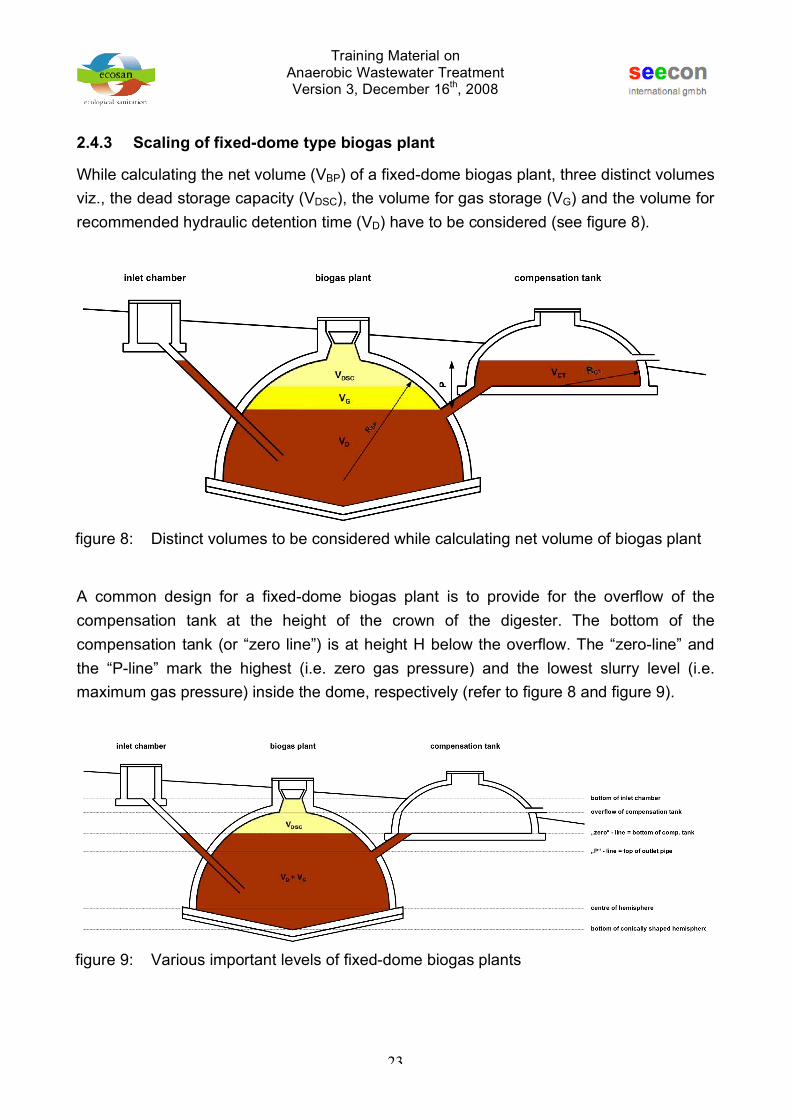
While calculating the net volume (VBP) of a fixed-dome biogas plant, three distinct volumes viz., the dead storage capacity (VDSC), the volume for gas storage (VG) and the volume for recommended hydraulic detention time (VD) have to be considered (see figure 8).
A common design for a fixed-dome biogas plant is to provide for the overflow of the compensation tank at the height of the crown of the digester. The bottom of the compensation tank (or “zero line”) is at height H below the overflow. The “zero-line” and the “P-line” mark the highest (i.e. zero gas pressure) and the lowest slurry level (i.e. maximum gas pressure) inside the dome, respectively (refer to figure 8 and figure 9).
figure 8: Distinct volumes to be considered while calculating net volume of biogas plant
figure 9: Various important levels of fixed-dome biogas plants

Training Material on Anaerobic Wastewater Treatment Version 3, December 16th, 2008
24
Example:
Calculate the dimensions of a fixed-dome type biogas plant for given digester volume (VD = ca. 12,000 liter) and gas storage volume (VG = ca. 1,350 liter).
The required net volume (VBP) of a fixed-dome biogas plant provides for detention volume (ca. 12,000 liter), gas storage volume (ca. 1,350 liter) and the dead storage capacity, which is determined by the equation for calculation of the spherical calotte volume. For ease of calculation the dead storage capacity is not considered, but it is assumed that by providing a conically shaped bottom (∆H = 0.30 to 0.45 m) to the digester the dead storage capacity is compensated.
The volume of a half round biogas plant is determined by the equation for calculation of the volume of a hemisphere (VHSP):
The equation of the volume of a hemisphere can be rearranged to calculate the halfmeter/radius (RBP) of the biogas plant. Assume the net volume of the biogas plant (VBP) is 13.5 m3 (13,500 liter). Hence halfmeter RBP is:
For construction of the dome, the radius RBP has to be increased by the thickness of the plaster (e.g. 0.02 meter). Hence, the actual readius of the brick dome is ca. 1.88 meter.
A common design for the compensation tank is to provide a hemisphere with the overflow at height H above the base (or “zero line”). Usually the radius RCT of the compensation tank is reduced by 1.5 cm per course of bricks above the overflow level (see figure 10).
VBP
= 12,000 + 1,3500 ! 13,500 l
VHSP
=2 i R
3i !
3
RBP
=3 i 13.5
2 i !3 " 1.86 m

Training Material on Anaerobic Wastewater Treatment Version 3, December 16th, 2008
25
The net volume of the compensation tank (VCT) is calculated by subtracting the volume of the free space above the overflow (RCT – H) from the volume of the hemisphere (see figure 11):
The net volume of the compensation tank (VCT) equals the gas storage capacity (VG).
figure 10: Conceptual sketch of compensation tank (above the overflow level radius RCT is reduced by 1.5 cm per course of bricks)
figure 11: Calculation of net volume of compensation tank
VCT
= VG=2 i R
CT
3i !
3" R
CT" H( )
2
i ! i RCT
"RCT
" H3
#$%
&'(
)
*+
,
-.

Training Material on Anaerobic Wastewater Treatment Version 3, December 16th, 2008
26
By trial and error (for H = 0.45 m and VG = 1.35 m3), RCT is about 1.00 meter.
For construction of the compensation tank, the radius RCT has to be increased by the thickness of the plaster (e.g. 0.02 meter). Hence, the actual readius of the brick dome is ca. 1.02 meter.
Maximum gas pressure occurs at a level P below the overflow level of the compensation tank, which is also the lowest slurry level (see figure 8). For calculation of level P the equation of the spherical calotte volume is applied to the total volume of the free space above maximum slurry level and the net volume of the compensation tank (VCT) (see figure 12).
By trial and error (for RBP = 1.86 m; H = 0.45 m and VCT = 1.35 m3), P is 0.69 meter.
Construction details and other important information
• An experienced company/organisation must do detailed project planning and construction of the biogas plant.
1.35 !2 i 1.00
3i "
3# 1.00 # 0.45( )
2
i " i 1.00 #1.00 # 0.45
3
$%&
'()
*
+,
-
./
figure 12: Calculation of “P-line”
0.692i ! i 1.86 "
0.69
3
#$%
&'() 0.452 i ! i 1.86 "
0.45
3
#$%
&'(+1.35

Training Material on Anaerobic Wastewater Treatment Version 3, December 16th, 2008
27
2.5 Slurry collection, treatment and application
The slurry, i.e. the fermented sludge, may be directly applied as liquid soil amendment to agricultural land or collected and further processed in socalled sludge drying beds for dewatering.
2.5.1 Direct application of the slurry
The slurry is directly applied to agricultrural plots using a trench or pipe system for distribution.
2.5.2 Advanced treatment of slurry in sludge drying beds
If the slurry is not used directly used, it may be collected and treated in sludge drying beds. The simplest way of providing for sludge drying beds is to partially dig up the ground and pile up the excavated soil to earthen bunds (figure 13). These perimeter bunds will also help in keeping surface run-off water from entering the sludge drying beds.
It is recommended to provide for at least 2 beds, which are used alternately. One bed receives slurry on a daily basis while the other lays idle or provides for additional resting period. The volume of each drying bed should allow for collection of slurry producted within a period of one month. Thus taking care on reduced infiltration and evaporation rates during rainy season.
figure 13: View of simple sludge drying beds

Training Material on Anaerobic Wastewater Treatment Version 3, December 16th, 2008
28
3 SAMPLE DESIGN PROBLEM „PRE-TREATMENT OF WASTEWATER IN A BIOGAS SETTLER“
A simple anaerobic on-site wastewater management concept that provides for the treatment of domestic wastewater (blackwater and/or greywater or combined wastewater) and recovery of biogas may comprise a biogas settler for solid-liquid separation up-stream an anaerobic baffled reactor and a constructed wetland or direct application of biogas settler effluent to a constructed wetland.
The required facilities are summarized below:
• primary treatment of raw wastewater in a biogas settler,
• treatment of (pre-treated) wastewater in an anaerobic baffled reactor and a constructed wetland or a constructed wetland only and
• optional tank for collection of treated wastewater, direct application without storage, infiltration or discharge to receiving water bodies.
3.1 Domestic wastewater quantification and characterisation
Domestic wastewater contains organic and inorganic matter in suspended, colloidal and dissolved forms. The concentration in the wastewater depends on the original
table 13: Domestic wastewater characteristics (excerpt)
item Range in values contgributed in wastes [12]
Biochemical oxygen demand, 5 days, 20 °C (BOD5) 45 - 54 Chemical oxygen demand 1.6 - 1.9 x BOD5
Total organic carbon 0.6 - 1.0 x BOD5 Total solids 170 - 220
Suspended solids 70 - 145 Grit (inorganic, 0.2 mm and above) 5 - 15
Grease 10 - 30 Total nitrogen N 6 - 12 Organic nitrogen ~ 0.4 x total N Free ammonia ~ 0.6 x total N
Nitrite - Nitrate 0.0 - 0.5 x total N
Total phosphorus, P 0.6 - 4.5 Organic phosphorus ~ 0.3 x total P
Inorganic (ortho- and polyphosphates) ~ 0.7 x total P Potassium (as potassium oxide K2O) 2.0 - 6.0

Training Material on Anaerobic Wastewater Treatment Version 3, December 16th, 2008
29
concentration in the water supply, and the uses to which the water has been put. The climate, and the wealth and habits of the people have a marked effect on the wastewater characteristics [12].
Raw domestic wastewater characteristics are shown in table 13.
The per capita daily water usage in India ranges from 180 to 300 litres im most sewered communities [12] though water consumption may be much higher. The values of biological oxygen demand (BOD) generally average 54 grams per person per day where the sewage collection system is separate from the storm collection system and is reasonably efficient [12].
According to the Central Public Health and Environmental Engineering Organisation (CPHEEO) water supply demand for Indian cities provided with piped water supply with sewerage amounts to 135 litres per capita per day. Break up of water demand is shown in table 14. At least 80 - 85 % of the water supplied returns as wastewater [12].
Example:
Calculate the daily wastewater production from a housing society with a population of 88 residents. Specific water consumption is about 170 litres per person per day and ca. 80% of water supplied contributes to wastewater production. Specific BOD load per person per day is set with 54 grams.
Considering a specific water consumption of ca. 170 litres per person per day, an 80% return of supplied water as wastewater and a population of 88 people, anticipated daily wastewater production (QD) is:
table 14: Break up of water requirements for domestic purposes according to CPHEEO „Manual on Water Supply and Treatment“
description quantity of water [13] [ l/cap/d] bathing 55
washing of clothes 20 flushing of WC 30
washing of house 10 washing of utensils 10
cooking 5 drinking 5
total 135
QD = 88 i 170 i 0.80 ! 12,000 l / d

Training Material on Anaerobic Wastewater Treatment Version 3, December 16th, 2008
30
Chemical oxygen demand (COD) levels in domestic wastewater are commonly twice as high as BOD5 levels. Considering a specific BOD load of ca. 54 grams per person per day and a specific wastwater production of ca. 135 litres per person per day (i.e. 80% return of supplied water), BOD concentration (CBOD-RAW) and COD concentration (CCOD-RAW) of the raw wastewater are calculated as follows:
3.2 Sizing of biogas settler
While designing a biogas settler for the pre-treatment of raw wastewater, five distinct volumes viz., the sludge accumulation volume (VSL), the volume for recommended hydraulic detention time (VD), the volume for the scum layer (VSC), the volume for gas storage (VG) and the dead storage capacity (VDSC), have to be considered.
Example:
Calculate the size of a biogas settler for the pre-treatment of domestic wastewater (ca. 12,000 litres per day) from a housing society with 88 residents.
According to a BORDA excel-sheet on the sizing of biogas settlers, BOD5 and COD removal by means of biogas settlers (at a hydraulic detention time of 24 hours) is about 36% and 34%, respectively. Based upon a raw wastewater concentrations of 400 mg BOD5/l and 800 mg COD/l, the effluent concentration regarding BOD (CBOD-EBS) and COD (CCOD-EBS) are calculated to be:
CBOD!RAW =54 i 1,000
135= 400 mg / l
CCOD!RAW = 2 i 400 = 800 mg / l
CBOD!EBS = 400 i 1! 0.36( ) = 256 mg BOD
5/ l
CCOD!EBS = 800 i 1! 0.34( ) = 528 mg COD / l

Training Material on Anaerobic Wastewater Treatment Version 3, December 16th, 2008
31
For calculation of the sludge accumulation volume (VSL) assume specific sludge production to be 0.0037 litres per gram BOD removed and desludging frequency to be 18 months (common desludging frequency is once in 3 – 5 years period).
A common design rule is for biogas settlers to provide a minimum hydraulic detention time (HRT) of at least 1 day (24 hours) at maximum depth of sludge and scum layer. The recommended volume for hydraulic retention time (VD) therefore is:
At 24 hours HRT, 15 – 20 % of VD can be taken for estimating the volume to be provided for the scum layer (VSC).
The required gas storage volume (VG) is determined by the theroretical specific methane production and the amount of COD removed. Theroretical specific methane (CH4) yield at standard temperature and pressure conditions (STP: 0°C and athmospheric pressure) is ca. 0.25 kg CH4 or about 0.35 litres CH4 per gram COD removed. Allowing for a safety margin of 25% and assuming the CH4 content of biogas to be 60% (common values are 50% to 70%), the gasholder storage volume (VG) is thus:
The required net volume of a biogas settler (VBS) provides for sludge accumulation volume (ca. 3,500 litres), hydraulic detetion volume (ca. 12,000 litres), scum accumulation volume (ca. 2,400 litres), gas storage volume (ca. 1,400 litres) and the dead storage capacity, which is determined by the equation for calculation of the spherical calotte volume. For ease of calculation the dead storage capacity is not considered, but it is assumed that by
VSL=0.0037 i 400 ! 256( ) i 12,000 i 30 i 18
1,000 i 1,000" 3.5 m
3
VD=12,000 i 1
1,000= 12,0 m
3
VSC
= 0.20 i 12.0 = 2.4 m3
VG= 1.25 i
0.35 i 800 ! 528( ) i 12,000
1,000 i 1,000 i 0.60" 2.4 m
3

Training Material on Anaerobic Wastewater Treatment Version 3, December 16th, 2008
32
providing a conically shaped bottom (∆H = 0.30 to 0.45 m) to the digester the dead storage capacity is compensated.
The volume of a half round biogas settler is determined by the equation for calculation of the volume of a hemisphere (VHSP):
The equation of the volume of a hemisphere can be rearranged to calculate the halfmeter/radius (RBS) of the biogas settler. Assume the net volume of the biogas settler (VBS) to be 20.3 m3 (20,300 liter). Hence halfmeter RBS is:
For construction of the dome, the radius RBS has to be increased by the thickness of the plaster (e.g. 0.02 meter). Hence, the actual readius of the brick dome is ca. 2.15 meter.
A common design for the compensation tank is to provide a hemisphere with the overflow at height H above the base (or “zero line”). Usually the radius RCT of the compensation tank is reduced by 1.5 cm per course of bricks above the overflow level (see figure 10).
The net volume of the compensation tank (VCT) is calculated by subtracting the volume of the free space above the overflow (RCT – H) from the volume of the hemisphere (see figure 11) and equals the gas storage capacity (VG).
VBS= 3.5 + 12.0 + 2.4 + 2.4 = 20.3m
3
VHSP
=2 i R
3i !
3
RBS=
3 i 20.3
2 i !3 " 2.13m
VCT
= VG=2 i R
CT
3i !
3" R
CT" H( )
2
i ! i RCT
"RCT
" H3
#$%
&'(
)
*+
,
-.

Training Material on Anaerobic Wastewater Treatment Version 3, December 16th, 2008
33
By trial and error (for H = 0.45 m and VG = 2.4 m3), RCT is 1.33 meter.
For construction of the compensation tank, the radius RCT has to be increased by the thickness of the plaster (e.g. 0.02 meter). Hence, the actual readius of the brick dome is ca. 1.35 meter.
Maximum gas pressure occurs at a level P below the overflow level of the compensation tank, which is also the lowest slurry level (see figure 8). For calculation of level P the equation of the spherical calotte volume is applied to the total volume of the free space above maximum slurry level and the net volume of the compensation tank (VCT) (see figure 12).
By trial and error (for RBS = 2.13 m; H = 0.45 m and VCT = 2.4 m3), P is 0.79 meter.
3.2.1 Post-treatment for biogas settler effluent
Depending upon the desired reuse and the respective degree of treatment, post-treatment of biogas settler effluent may happen in an anaerobic baffled reactor (for advanced anaerobic treatment) and/or direct application to a constructed wetland.
For more detailed information on the post-treatment for biogas settler effluent using constructed wetland systems please refer to the training material on constructed wetlands.
2.4 !2 i 1.33
3i "
3# 1.33# 0.45( )
2
i " i 1.33 #1.33# 0.45
3
$%&
'()
*
+,
-
./
0.792i ! i 2.13 "
0.79
3
#$%
&'() 0.452 i ! i 2.13 "
0.45
3
#$%
&'(+ 2.4

Training Material on Anaerobic Wastewater Treatment Version 3, December 16th, 2008
34
4 BIBLIOGRAPHY
[1] Kossmann, W. et al (unknown). Biogas Digest (Volume I) – Biogas Basics [2] Seghersbetter (2002). Anaerobic Digestion in Wastewater Treatment
http://www.scientecmatrix.com/seghers/tecm/scientecmatrix.nsf/_/FF976EA7B13F69F5C1256B5A005418EC/$file/AnaerobicDigestionInWasteWaterTreatment.pdf. (last accessed on March 15th, 2002)
[3] Hammer, M., (2002). Ugandan Biogas Plants – State of the Art [4] Scientific Research Council (2006). http://www.src-jamaica.org/
last accessed August 18th, 2006 [5] Lebofa, M. (2005). conference documentation “Ecological sanitation: a sustainable, integrated
solution” May 23-26th, 2005 in Durban, South Africa [6] Personal communication between Mr. H.P. Mang and Mr. J. Heeb during the „short course in ecosan
in the developing world“, August 14 – 18th, 2006, Norway [7] Bremen Overseas Research and Development Association (2006). http://www.borda-net.org/
last accessed August 18th, 2006 [8] Personal communication with Mr. R. Pai (BORDA) on August 4th, 2006 [9] SANIMAS (2005). Informed Choice Catalogue (PP-Presentation)
http://sanimas.waspola.org/product.html [10] Werner, U., Stöhr, U., Hees, N. (1989). Biogas plants in animal husbandry [11] Sasse, L. (1988). Biogas Plants [12] Arceivala, S.J., Asolekar, S.R. (2007). Wastewater Treatment for Pollution Control and Reuse (Third
Edition). Tata McGraw-Hill Publishing Company Limited, ISBN 0-07-062099-7 [13] CPHEEO (1999). Manual on Water Supply and Treatment
(downloadable from: http://cpheeo.nic.in/) (last accessed on February 15th, 2007)

Training Material on Anaerobic Wastewater Treatment Version 3, December 16th, 2008
35
5 SKETCHES, TECHNICAL DRAWINGS

Training Material on Anaerobic Wastewater Treatment Version 3, December 16th, 2008
36
figure 14: Conceptual sketch of toilet-linked biogas unit

Training Material on Anaerobic Wastewater Treatment Version 3, December 16th, 2008
37
(photo: N. Zimmermann)
(photo: N. Zimmermann)
(photo: N. Zimmermann)
(photo: N. Zimmermann)
figure 15: Construction of biogas settler (clockwise from top left: excavated pit for biogas settler; a first layer of P.C.C. has been poured directly on the ground; the foundation of the biogas settler is made from P.C.C.; the first brick is laid using a “radius stick”)

Training Material on Anaerobic Wastewater Treatment Version 3, December 16th, 2008
38
(photo: N. Zimmermann)
(photo: N. Zimmermann)
(photo: K.P. Pravinjith)
(photo: K.P. Pravinjith)
figure 16: Construction of biogas settler (detail “radius stick”; the outside of the wall is sealed with cement mortar; biogas settler and compensation tank; fixing and sealing of lid)

Training Material on Anaerobic Wastewater Treatment Version 3, December 16th, 2008
seecon gmbh Bahnhofstrasse 2 6110 Wolhusen, Switzerland Phone: +41-79-3666850 Email: [email protected] Web: http://www.seecon.ch
Ecosan Services Foundation (ESF) "Vishwa Chandra" 1002/42 Rajendra Nagar Pune – 411030, Maharashtra, India Phone/Fax: +91-(0)20-64000736 Email: [email protected] Web: http://www.ecosanservices.org