Traffic Control Signal Design Manual - PE Civil...
191
Transcript of Traffic Control Signal Design Manual - PE Civil...


Traffic Control Signal Design Manual Connecticut Department of Transportation Bureau of Engineering and Construction Division of Traffic Engineering 2009 This manual presumes that a traffic engineering study has determined that traffic
signal control is needed. This document is intended to provide guidelines for certain considerations involved in the design of such devices.
Some of the information contained in this manual reflects departmental policy and
State Traffic Commission Regulations as of July 2009. In the event that policy or regulations are changed such that they conflict with information in this manual, the revised policy / regulations will supersede.
MANUAL REVIEW COMMITTEE Robin M. Waterman Mark F. Makuch, P.E. LeVance H. James Michael J. Cloutier
David M. Fabry, Chairman

i
TABLE OF CONTENTS
LIST OF FIGURES ....................................................................................................... F-1
REFERENCES.............................................................................................................. R-1
1 PRELIMINARY CONSIDERATIONS.................................................................... 1-1
2 DESIGN VOLUMES........................................................................................... 2-1
3 INTERSECTION CHANNELIZATION DESIGN GUIDELINES ............................... 3-1 Left-Turn Lanes.............................................................................................................. 3-1
Other Left-Turn Treatments..................................................................................................3-1 Right-Turn Lanes ........................................................................................................... 3-2 Dual Turn Lanes............................................................................................................. 3-2
Throat Width.........................................................................................................................3-2 Acceptance Carry Through Length.......................................................................................3-3 Widening Approaching Through Lanes................................................................................3-3 Special Pavement Markings..................................................................................................3-3 Signal Indications..................................................................................................................3-3 Opposing Left-Turn Traffic ..................................................................................................3-3 Turning Templates ................................................................................................................3-3
4 PHASING .......................................................................................................... 4-1 Left-Turn ........................................................................................................................ 4-1
Advance Green (Protected/Permitted) ..................................................................................4-1 Advance Green (Protected Only)..........................................................................................4-3 Lag Green .............................................................................................................................4-4
Lag Green (Permitted/Protected) ..................................................................................4-5 Lag Green (Protected Only) ..........................................................................................4-6 Lead – Lag .....................................................................................................................4-7
Dual Advance Green.............................................................................................................4-8 Directional Separation ..........................................................................................................4-8 Quad......................................................................................................................................4-8
Quad (Protected/Permitted)...........................................................................................4-9 Quad (Protected Only)...................................................................................................4-10 Dual Quad (Protected/Permitted)..................................................................................4-11 Dual Quad (Protected Only)..........................................................................................4-12 Dual Quad with Exclusive Pedestrian Phase ................................................................4-13
NEMA Ring Diagrams................................................................................................... 4-14 Overlaps ......................................................................................................................... 4-16
5 CAPACITY ANALYSIS ...................................................................................... 5-1 Lost Time ....................................................................................................................... 5-1 Cycle Length - Webster's Equation ................................................................................ 5-1

ii
6 SIGNAL TIMING................................................................................................ 6-1 Maximum Green............................................................................................................. 6-1 Minimum Green ............................................................................................................. 6-1 Vehicle Extension........................................................................................................... 6-1 Gap Reduction................................................................................................................ 6-2 Variable Initial................................................................................................................ 6-2 Min/Max Timing Range (Town Signals) ....................................................................... 6-3 Clearance Intervals ......................................................................................................... 6-3
Conflict Points ......................................................................................................................6-3 Yellow...................................................................................................................................6-5 Red ........................................................................................................................................6-6
7 VEHICLE DETECTION ...................................................................................... 7-1 Controller Operation....................................................................................................... 7-1 Detector Types ............................................................................................................... 7-1 Loop Detector Mode/Features........................................................................................ 7-3 Detection Design Guidelines.......................................................................................... 7-4
Arterial Detection..................................................................................................................7-4 Dilemma Zone ......................................................................................................................7-5 Left-Turn Lane Detection .....................................................................................................7-9 Sidestreet Detection ..............................................................................................................7-10 System Detection ..................................................................................................................7-10 Miscellaneous .......................................................................................................................7-10 Loop Detector Placement......................................................................................................7-12
Microwave Detection Guidelines ................................................................................... 7-13 Characteristics.......................................................................................................................7-13 Placement..............................................................................................................................7-13 Special Application...............................................................................................................7-14
Video Detection Guidelines ........................................................................................... 7-14 Advantages............................................................................................................................7-14 Disadvantages .......................................................................................................................7-14 Camera Placement.................................................................................................................7-15
8 FLASHING OPERATION ................................................................................... 8-1 Programmed Flash.......................................................................................................... 8-1 Maintenance Level ......................................................................................................... 8-1

iii
9 PRE-EMPTION ................................................................................................. 9-1 Emergency Vehicle Pre-Emption ................................................................................... 9-1
System Types ........................................................................................................................9-1 Coded Light (Optical)....................................................................................................9-1 Hardwire........................................................................................................................9-2 Radio..............................................................................................................................9-2 Siren...............................................................................................................................9-2
Emergency Vehicle Pre-emption Design Guidelines............................................................9-2 Sample Pre-emption Settings Block......................................................................................9-4
Railroad Pre-Emption..................................................................................................... 9-5 Railroad Pre-emption Design Guidelines..............................................................................9-5 Railroad Pre-emption Track Circuit Timing Block...............................................................9-7
Ramp Pre-emption.......................................................................................................... 9-8 Ramp Pre-emption Design Guidelines..................................................................................9-8
Pre-Emption Definitions................................................................................................. 9-10 Pre-Emption Settings Definitions................................................................................... 9-11
10 TRAFFIC SIGNAL EQUIPMENT ........................................................................ 10-1 Signal Head Location ..................................................................................................... 10-1
Lateral Placement..................................................................................................................10-1 Longitudinal Placement ........................................................................................................10-2 Special Applications .............................................................................................................10-2
Visual Shielding Devices ............................................................................................... 10-3 Visors ....................................................................................................................................10-3 Louvers .................................................................................................................................10-3 Visibility Limiting Signals....................................................................................................10-3 Backplates .............................................................................................................................10-3
Signal Lens Size and Type ............................................................................................. 10-5 Signal Support Structures............................................................................................... 10-5
Type ......................................................................................................................................10-5 Placement..............................................................................................................................10-6 Finish ....................................................................................................................................10-7 Use of Utility Poles...............................................................................................................10-7 Span Wire Design Guidelines...............................................................................................10-8 Mast Arm Design Guidelines................................................................................................10-9
11 PEDESTRIAN/BICYCLIST CONSIDERATIONS .................................................. 11-1 Pedestrian Actuated Side Street Green........................................................................... 11-2 Pedestrian Actuated Walk/Don’t Walk .......................................................................... 11-2
Accessible Pedestrian Signals (APS)....................................................................................11-3 Countdown Pedestrian Signals .............................................................................................11-4
12 SIGNING AND PAVEMENT MARKINGS ............................................................ 12-1
13 MERRITT PARKWAY GUIDELINES................................................................... 13-1

iv
14 FLASHING MESSAGE SIGNS ........................................................................... 14-1 Inadequate Visibility to a Queue of Stopped Vehicles................................................... 14-2
Determining the Critical Queue ............................................................................................14-2 Locating the sign...................................................................................................................14-2 Determining time when Flashing Operation Occurs.............................................................14-3
Inadequate Visibility to Signal Heads ............................................................................ 14-6 Locating the sign...................................................................................................................14-6 Determining time when Flashing Operation Occurs.............................................................14-6
15 ELECTRICAL CONSIDERATIONS ..................................................................... 15-1 General ........................................................................................................................... 15-1
Governing Codes, Regulations, and Standards.....................................................................15-1 Other Controlling Conditions ...............................................................................................15-2
Ownership and Maintenance .........................................................................................15-2 Funding..........................................................................................................................15-3
Pre-design Site Inspection .............................................................................................. 15-3 Handholes and Cast Iron Junction Boxes....................................................................... 15-4
Handholes .............................................................................................................................15-5 Cast Iron Junction Boxes ......................................................................................................15-5
Electrical Conduits ......................................................................................................... 15-5 Types.....................................................................................................................................15-6 Fill .........................................................................................................................................15-6 Installation Methods..............................................................................................................15-7
Surface ...........................................................................................................................15-7 In Trench........................................................................................................................15-7 Under Roadway .............................................................................................................15-7 In Structure ....................................................................................................................15-7 Under Railroad Tracks ..................................................................................................15-8
Vehicle Detectors ........................................................................................................... 15-9 Inductive Loop Detector (ILD).............................................................................................15-9
Theory of Operation ......................................................................................................15-9 Splicing and Number of Turns .......................................................................................15-9 Sawcut............................................................................................................................15-10 Lead-In Cable ................................................................................................................15-10
Video Image Detector System (VIDS) .................................................................................15-11 Microwave Detector..............................................................................................................15-11 Others....................................................................................................................................15-11
Traffic Signal and Pedestrian Wiring ............................................................................. 15-12 Utility Considerations..................................................................................................... 15-14
Utility Companies .................................................................................................................15-14 Use of Utility Poles...............................................................................................................15-17 Overhead...............................................................................................................................15-21 Beneath Transmission Lines .................................................................................................15-21 Underground .........................................................................................................................15-22 Utility Meeting......................................................................................................................15-23
Electric Service............................................................................................................... 15-24 Source ...................................................................................................................................15-24 Traffic Signal Requirements .................................................................................................15-24 Metered .................................................................................................................................15-25 Unmetered.............................................................................................................................15-25 Request for Service/Power Letter .........................................................................................15-25
Telephone Service .......................................................................................................... 15-26 Powered Signs ................................................................................................................ 15-26
Alternate Flashing Signals on Warning Sign........................................................................15-27

v
Internally Illuminated Warning or Advisory Sign ................................................................15-27 Interconnect .................................................................................................................... 15-28
Type ......................................................................................................................................15-28 Twisted Pair Cable ........................................................................................................15-28 Fiber Optic Cable ..........................................................................................................15-29 Signal Cable...................................................................................................................15-29
Structural Design for Span Poles.................................................................................... 15-31 Plans, Specifications and Estimates ............................................................................... 15-34
Plans......................................................................................................................................15-34 Specifications........................................................................................................................15-34 Estimates ...............................................................................................................................15-35
Miscellaneous................................................................................................................. 15-36 Location Numbering System ................................................................................................15-36 Uninterruptible Power Source...............................................................................................15-37 Illumination...........................................................................................................................15-37 Use of Construction Notes ....................................................................................................15-38 Use of Technical Notes.........................................................................................................15-38 Scrap and Salvaged Material.................................................................................................15-38
16 SIGNAL PLAN LAYOUT ................................................................................... 16-1
17 SIGNAL SYSTEMS ........................................................................................... 17-1 Signal System Coordination Types ................................................................................ 17-1 Procedure for Determining System Type ....................................................................... 17-2 Traffic Engineering Analysis ......................................................................................... 17-2 Systems Analysis............................................................................................................ 17-3 Selection of Alternative Systems.................................................................................... 17-3 Signal Coordination System Selection Work Sheet ....................................................... 17-4 Signal System Concurrence Sheet.................................................................................. 17-5 Signal System Design..................................................................................................... 17-6 Time-Space Diagrams .................................................................................................... 17-7 Closed Loop System Design .......................................................................................... 17-10 System Detection............................................................................................................ 17-12 Time Base System Design.............................................................................................. 17-15
18 SIGNAL OWNERSHIP AND MAINTENANCE...................................................... 18-1 Ownership and Maintenance .......................................................................................... 18-1 Installation Costs of Warranted Signals ......................................................................... 18-2 Electrical Energy Costs .................................................................................................. 18-4
19 SIGNAL DESIGN CHECK LIST ......................................................................... 19-1 General ........................................................................................................................... 19-1 Timing and Sequence ..................................................................................................... 19-4 Estimates for Projects ..................................................................................................... 19-5
20 CLEAR ZONE CHART ...................................................................................... 20-1

vi
21 DRAFTING GUIDELINES FOR CONSULTANTS ................................................. 21-1 Preliminary Design Requirements.................................................................................. 21-1 Semi-final Design Requirements.................................................................................... 21-2 Final Design Requirements ............................................................................................ 21-2 Legend Used on Signal Plans......................................................................................... 21-4 Roadside and ROW Conventions................................................................................... 21-5 Pavement Markings........................................................................................................ 21-6 Signal Appurtenances..................................................................................................... 21-7 Sample Intersection Layout............................................................................................ 21-8 CADD Text Sizes........................................................................................................... 21-9 Traffic Signal Faces........................................................................................................ 21-10 Movement Diagram........................................................................................................ 21-11 Energy Block.................................................................................................................. 21-12 Metric Dimensional Guide ............................................................................................. 21-13 Commonly Used Construction Notes............................................................................. 21-14
22 GLOSSARY ...................................................................................................... 22-1
23 SIGNAL MANUAL UPDATE SHEET.................................................................. 23-1

F-1
LIST OF FIGURES
FIGURE 3-1 DESIGN OF DUAL LEFT-TURN LANES ................................................................. 3-4 FIGURE 4-1 ADVANCE GREEN (PROTECTED/PERMITTED)...................................................... 4-2 FIGURE 4-2 ADVANCE GREEN (PROTECTED ONLY)............................................................... 4-3 FIGURE 4-3 LAG GREEN (PERMITTED/PROTECTED)............................................................... 4-5 FIGURE 4-4 LAG GREEN (PROTECTED ONLY)........................................................................ 4-6 FIGURE 4-5 LEAD-LAG.......................................................................................................... 4-7 FIGURE 4-6 QUAD (PROTECTED/PERMITTED) AND PHASE DIAGRAM .................................... 4-9 FIGURE 4-7 QUAD (PROTECTED ONLY) AND PHASE DIAGRAM............................................ 4-10 FIGURE 4-8 DUAL QUAD (PROTECTED/PERMITTED) AND PHASE DIAGRAM ........................ 4-11 FIGURE 4-9 DUAL QUAD (PROTECTED ONLY) AND PHASE DIAGRAM ................................. 4-12 FIGURE 4-10 DUAL QUAD WITH EXCLUSIVE PEDESTRIAN PHASE ......................................... 4-13 FIGURE 4-11 NEMA SINGLE RING DIAGRAM ....................................................................... 4-14 FIGURE 4-12 NEMA DUAL RING, QUAD/SEQUENTIAL DIAGRAM......................................... 4-14 FIGURE 4-13 NEMA DUAL RING, DUAL QUAD (QUAD LEFT-TURN) DIAGRAM.................... 4-15 FIGURE 4-14 NEMA DUAL RING, SEQUENTIAL/QUAD DIAGRAM......................................... 4-15 FIGURE 4-15 TECHNICAL NOTES FOR A NON-STANDARD OVERLAP...................................... 4-17 FIGURE 6-1 CONFLICT POINTS............................................................................................... 6-4 FIGURE 7-1 DILEMMA ZONE TRAP CHECK (ONE DETECTOR)................................................ 7-7 FIGURE 7-2 DILEMMA ZONE TRAP CHECK (TWO DETECTORS) ............................................. 7-8 FIGURE 7-3 LEFT-TURN LANE DETECTION............................................................................ 7-9 FIGURE 7-4 LOOP DETECTOR PLACEMENT .......................................................................... 7-12 FIGURE 9-1 SAMPLE PRE-EMPTION SETTINGS BLOCK ........................................................... 9-4 FIGURE 9-2 RAILROAD PRE-EMPTION TRACK CIRCUIT TIMING BLOCK ................................. 9-7 FIGURE 10-1 TYPES OF VISIBILITY LIMITING DEVICES.......................................................... 10-4 FIGURE 10-2 Y-TYPE SPAN SIGNAL SUPPORT ....................................................................... 10-8 FIGURE 10-3 COMMONLY USED STEEL POLE SIZES .............................................................. 10-9 FIGURE 10-4 MAST ARM ASSEMBLY PROFILE VIEW ........................................................... 10-11 FIGURE 10-5 MAST ARM ASSEMBLY PLAN VIEW................................................................ 10-12 FIGURE 14-1 LOCATING THE SIGN (INADEQUATE VISIBILITY TO A QUEUE)........................... 14-4 FIGURE 14-2 SEQUENTIAL PHASING WITH A “DUMMY” PHASE ............................................. 14-5 FIGURE 14-3 LOCATING THE SIGN (INADEQUATE VISIBILITY TO SIGNAL HEADS) ................. 14-9 FIGURE 14-4 QUAD PHASING WITH SIGN ON ONE ARTERY APPROACH................................ 14-10 FIGURE 14-5 QUAD PHASING WITH SIGNS ON BOTH ARTERY APPROACHES ........................ 14-11 FIGURE 14-6 SEQUENTIAL PHASING WITH A “DUMMY” PHASE ........................................... 14-12 FIGURE 15-1 COMMONLY USED CONDUIT............................................................................. 15-6
Page

F-2
FIGURE 15-2 TRAFFIC SIGNAL CABLES ............................................................................... 15-13 FIGURE 15-3 PRIVATELY OWNED POWER COMPANIES........................................................ 15-14 FIGURE 15-4 MUNICIPAL OWNED POWER SERVICES ........................................................... 15-15 FIGURE 15-5 POWER COMPANY JURISDICTION IN CONNECTICUT ........................................ 15-16 FIGURE 15-6 NORTHEAST UTILITIES DISTRICT OFFICES AND LOCATIONS........................... 15-17 FIGURE 15-7 UTILITY POLE DATA....................................................................................... 15-18 FIGURE 15-8 TYPICAL UTILITY POLE CONSTRUCTION ........................................................ 15-19 FIGURE 15-9 POLE-TO-POLE GUY....................................................................................... 15-20 FIGURE 15-10 CALL-BEFORE-YOU-DIG COLOR CODE.......................................................... 15-23 FIGURE 15-11 SERVICE CONDUCTOR RESISTANCE ................................................................ 15-24 FIGURE 15-12 INTERCONNECT CABLE ATTACHMENT LIST.................................................... 15-30 FIGURE 15-13 LOCATION NUMBERING SYSTEM .................................................................... 15-36 FIGURE 16-1 TYPICAL PHASE ASSIGNMENTS ........................................................................ 16-2 FIGURE 16-2 SEQUENCE AND TIMINGS .................................................................................. 16-3 FIGURE 16-3 SYSTEM INFORMATION BLOCKS ....................................................................... 16-4 FIGURE 16-4 DESIGN INFORMATION BLOCKS........................................................................ 16-5 FIGURE 16-5 TRAFFIC CONTROL SIGNAL PLAN OFFICE RECORD .......................................... 16-6 FIGURE 16-6 CONSTRUCTION NOTES SECTION...................................................................... 16-7 FIGURE 16-7 INTERSECTION LAYOUT.................................................................................... 16-8 FIGURE 17-1 SIGNAL COORDINATION SYSTEM SELECTION WORK SHEET............................. 17-4 FIGURE 17-2 SIGNAL SYSTEM CONCURRENCE SHEET ........................................................... 17-5 FIGURE 17-3 TIME SPACE DIAGRAM EXAMPLE ..................................................................... 17-9 FIGURE 20-1 RECOMMENDED CLEAR ZONE DISTANCES........................................................ 20-1 FIGURE 21-1 COMMONLY USED CONSTRUCTION NOTES..................................................... 21-14

R-1
REFERENCES
1. "Traffic Signals: Capacity and Timing Analysis" by R. Akcelik, March 1981 Australian Road Research Board - Research Report ARR No. 123.
2. Connecticut Department of Transportation Highway Design Manual, latest edition. Website: www.ct.gov/dot/
3. Highway Capacity Manual, Transportation Research Board, latest edition. Website: www.trb.org/bookstore/
4. Highway Capacity Software, McTrans Center, University of Florida, Gainesville, Florida. Website: www.mctrans.ce.ufl.edu/featured/
5. Manual of Traffic Signal Design – Institute of Transportation Engineers, latest edition.
6. Manual on Uniform Traffic Control Devices For Streets And Highways, US Department of Transportation Federal Highway Administration - latest edition. Website: www.mutcd.fhwa.dot.gov/
7. NCHRP Synthesis 225 - "Left-Turn Treatments at Intersections" Transportation Research Board National Research Council, Washington, D.C. 1996. Website: www.trb.org/bookstore/
8. National Electric Code - latest edition. Website: www.nfpa.org/
9. National Electric Safety Code - latest edition. Website: www.ieee.org/
10. NEMA Standards Publication No. TS-2 1992, Traffic Controller Assemblies. Website: www.nema.org/
11. Public Roads Capacity Analysis Techniques for Design of Signalized Intersections, Reprinted from Public roads Vol. 34 No. 9 & 10 , August 1967 & October 1967, US Department of Transportation Federal Highway Administration.
12. Regulations of the Connecticut State Agencies Vol. II Section 16-243 -Construction and Maintenance Standards Governing Traffic Signals Attached to Public Service Company Poles. Website: www.state.ct.us/dpuc/
13. Standard Specifications for Roads, Bridges and Incidental Construction - latest edition, Connecticut Department of Transportation, and supplement. Website: www.ct.gov/dot/
R-2
14. State Traffic Commission Administrative Regulations - section 14-298-700 to 14-298-741.
Website: www.ct.gov/dot/
15. Traffic Control Systems Handbook FHWA – HOP – 06 – 006, Federal Highway Administration, Office of Transportation Management, October 2005. Website: www.ops.fhwa.dot.gov/publications/publications.htm
16. Transportation and Traffic Engineering Handbook - fifth edition, Institute of Transportation Engineers.
17. Catalog of Signs – Connecticut Department of Transportation, latest edition.
18. CADD/Graphics/GIS Manual.
19. State of Connecticut, Department of Transportation, Bureau of Engineering and Highway Operations – Functional Specifications for Traffic Control Equipment, latest edition.
20. Transportation Quarterly – Signal Change Intervals and Intersection Geometry – January 1984, Volume XXXVIII, No. 1.
21. Consulting Engineer’s Manual, prepared by Bureau of Engineering and Construction, Office of Engineering, Division of Consultant Design – latest edition.

1-1
1 PRELIMINARY CONSIDERATIONS
Before a traffic control signal is designed it must be determined if the signal is warranted and needed through a review of the volumes, sightlines, accident experience, turning movements, geometry and input from local officials.
Once it is determined that a traffic control signal will be installed, it is necessary to perform preliminary analysis to determine geometry, lane arrangement and phasing. The geometric design of an intersection involves several critical decisions about the number and use of lanes to be provided on each approach. Factors to be considered include but are not limited to the functional classification of the roadway; the proximity of nearby signals; the degree of need for platoon cohesion; level of service and; volume to capacity ratios.
When installing or revising a traffic control signal, the designer must take into account the physical setting in which the signal will be located. Visiting the site to get a "feel for" the area is important so that the designer can understand the landscape and the community in which the design will have to assimilate. Sensitivity to the placement of appurtenances to minimize their aesthetic impact on adjacent development, particularly residential, should be considered. An effort should be made to limit environmental impacts while maintaining safety and mobility. The designer should always be cognizant of where signal equipment will be placed in relation to existing appurtenances. A survey may be needed to show above-ground and under-ground utilities. Also, test pits may be required depending on information from the survey. If the signal equipment cannot be located without potential utility conflicts, the designer should bring it to the attention of the Division of Traffic Engineering.
In some instances design criteria set forth by the Regulations of the State Traffic Commission (reference 14) are more stringent than those of the Manual on Uniform Traffic Control Devices (MUTCD) (reference 6). In those cases, the Regulations of the State Traffic Commission will govern.
2-1
2 DESIGN VOLUMES
In design projects, volumes are usually projected to some design year in the future, usually a 20 year projection. These future volumes should be used to determine traffic signal phasing, lane arrangements and storage length requirements. Signal timings and cycle length for these future volumes should also be evaluated to verify that proposed phasing and lane arrangements would remain valid. This information is also utilized in air quality analysis.
The traffic signal timings and cycle length needed for when the signal is first turned on should also be determined. These timings should be based on operational traffic volumes expected for approximately three years after completion of construction (five or more years after design). The 20 year traffic volumes should be adjusted to operational volumes by any appropriate method to provide for a.m., p.m., other peaks and off peaks, and appropriate timing plans should be included in the project.
Air Quality Assessment is required for projects where the anticipated level of service is D or worse. In those cases, localized carbon monoxide (CO) assessment must be conducted by the Bureau of Policy and Planning to determine air quality conformity.

3-1
3 INTERSECTION CHANNELIZATION DESIGN GUIDELINES
Left-Turn Lanes
1. Left-turn lanes should be considered to address capacity concerns or if land-use changes are expected to produce significant shifts in local traffic patterns such as increases in left-turn demand. Signalized capacity analysis procedures should be used to determine lane arrangements.
2. In terms of safety, left-turn lanes should be considered at intersection approaches that experience a significant number of accidents involving left-turning vehicles. Another safety application would be to include left-turn lanes where it is critical to protect queued left-turning vehicles from through traffic.
3. Left-turn lanes may also be considered based on approach geometry. One example of this would be at a location where the stopping sight distance to the intersection is limited. In this case it may be appropriate to include left-turn lanes regardless of demand volume. The provision of a left-turn lane under these conditions may help to reduce the potential for rear-end accidents.
4. In some cases left-turn lanes may be added without additional widening of the road by removing parking, narrowing lanes, or a combination of the two.
5. If left-turn lanes are provided on both approaches of the same road, it is preferable to locate them directly opposite each other. This allows the left-turning driver on each approach to view oncoming through traffic without obstruction by left-turning vehicles on the opposite approach.
Other Left-Turn Treatments
In some cases, the highway geometry and traffic characteristics prevent efficient operation of intersections with direct left-turns. Special solutions have been implemented to handle these situations. These include directional crossovers, jug handles and at-grade loops.
The intent of special design treatments is to eliminate the left-turn movement and its required signal phase, without prohibiting the actual movement. Traffic is diverted through the intersection as a right-turn or through movement, whereupon it completes the "left-turn" on a cross street again as either a right or through movement.
The operational advantages of these designs are that they enable simple phasing, thereby facilitating corridor signal progression schemes. Potential concerns with these applications relate to the weaving movement required in some cases and the result that "left-turn" traffic must go through the intersection twice.

3-2
Right-Turn Lanes
Right-turn lanes should also be considered to address capacity concerns or if land-use changes are expected to produce significant shifts in local traffic patterns such as increases in right-turn demand. Signalized capacity analysis procedures should be used to determine lane arrangements.
Dual Turn Lanes
The use of a dual or double turning lane either on two exclusive lanes or on one exclusive lane and a second combination lane should be considered when:
• There is not sufficient space to provide the calculated length of a single turn lane;
• The calculated length of a single turn lane becomes prohibitive;
• The necessary time for a protected left-turn phase becomes unattainable to meet the level-of-service criteria (average delay per vehicle); or
• The volume to capacity ratio is greater than or equal to 0.90.
Dual right-turn lanes do not work as well as dual left-turn lanes because the drivers are positioned on the opposite side of the vehicle from the turn which tends to restrict their view of the turn area. If practical, the designer should find an alternative means to accommodate the high number of right-turning vehicles. For example, a turning roadway may accomplish this purpose. Dual left-turn or right-turn lanes onto an expressway entrance ramp should be discouraged because of the potential negative impact on expressway operations.
Dual turn lanes (both lanes exclusive) can potentially discharge approximately 1.9 times the number of cars that could discharge from a single exclusive turn lane. However, to work properly, several design elements must be carefully considered. Figure 3-1 presents both dual left-turn and right-turn lanes to illustrate the more important design elements. The designer should consider the following:
Throat Width
Because of the off-tracking characteristics of turning vehicles, the normal width of two travel lanes may be inadequate to properly receive two vehicles turning abreast. Therefore, the receiving throat width may need to be widened. For 90-degree intersections, the designer can expect that the throat width for dual turn lanes will be approximately 30-36 feet (9 - 11 m). If the angle of turn is less than 90-degrees, it may be acceptable to provide a narrower width. When determining the available throat width, the designer can assume that the paved shoulder, if present, will be used to accommodate two-abreast turns. It is also highly desirable to have a center island on the receiving leg of the turn, to provide good definition of the entry throat area.

3-3
Acceptance Carry Through Length
There should be an adequate length of two lanes provided on the downstream section of road receiving the double turn movement to safely merge back to a single lane. The Department’s Highway Design Manual (reference 2) should be used for preliminary design purposes. A common practice in determining the length of carry through is to provide a length equal to twelve times the green interval allotted to the movement. In this case, the carry through length should be measured from the point where the turning vehicles have completed their turn maneuver and not from the stop bar.
Widening Approaching Through Lanes
If a 30 foot (9 m) or 36 foot (11 m) throat width is provided to receive dual turn lanes, the designer should also consider how this will affect the through traffic approaching from the other side. See Figure 3-1. The designer should also ensure that the through lanes line up relatively well to ensure a smooth flow of traffic through the intersection.
Special Pavement Markings
As illustrated on Figure 3-1, special pavement markings can effectively guide two lines of vehicles turning abreast. The guide markings are terminated when the turning movements are sufficiently oriented on the receiving through lanes. The Division of Traffic Engineering will help determine the selection and placement of any special pavement markings.
Signal Indications
Dual turn lanes provide for major traffic movements and require two signal faces.
Opposing Left-Turn Traffic
If simultaneous opposing left-turns will be allowed, the designer should ensure that there is sufficient space for all turning movements. This is always a factor, but dual left-turn lanes can cause special problems. If space is unavailable, it may be necessary to alter the signal phasing to allow the two directions of traffic to move through the intersection on separate phases.
Turning Templates
All intersection design elements for dual turn lanes must be checked by using the applicable turning templates.

3-4
Figure 3-1 Design of Dual Left-Turn Lanes

4-1
4 PHASING
The simplest and most common type of phasing is two-phase operation. In a two-phase sequence there is a phase for main line traffic and another phase for the cross street. The left-turn movements must yield to opposing traffic, turning only when there is an adequate gap in the opposing traffic. The next most commonly added phasing is for left-turns. Generally, actuated left-turn phasing is preferable.
More intersectional problems are caused by left-turning traffic than any other vehicular movement. The identification of such a problem may be obtained through accident analysis or capacity analysis. The selection of any combination of lane assignments or signal treatments should be based upon the overall effectiveness of the control schemes available. These problems can be treated in a number of ways. The objective of any treatment is either an increase in capacity, a decrease in accident potential, or a combination of the two. For additional information on left-turn treatments refer to NCHRP Synthesis 225–Left-Turn Treatments at Intersections (reference 7).
Left-Turn
The following outlines the basic sequences used to accommodate left-turn movements:
Advance Green (Protected/Permitted)
This is a sequence in which the left-turning vehicles from only one approach are first allowed to move together with the through traffic on that approach while the opposing traffic is stopped, and then are also permitted to move on the arterial phase which follows.
The protected left-turn portion of the phase is terminated through the display of a yellow arrow and a circular green simultaneously. The advance can be either fixed time or actuated.
This type of phasing is preferable with the provision of an exclusive left-turn lane, but may also be used without an exclusive left-turn lane.
The signal indication displays for this type of phasing are shown on Figure 4-1.

4-2
Figure 4-1 Advance Green (Protected/Permitted)

4-3
Advance Green (Protected Only)
This is a sequence in which the left-turning vehicles from only one approach are allowed to move together with the through traffic on that approach, but then not permitted to move on the arterial phase which follows.
To implement this type of phasing an exclusive left-turn lane is required. An exclusive left-turn signal is provided to control this left-turn movement. The protected advance is terminated by the display of a yellow arrow followed by a red arrow on the left-turn signal.
The signal indication displays for this type of phasing are shown on Figure 4-2.
Figure 4-2 Advance Green (Protected Only)

4-4
Lag Green
This is a sequence in which left-turns in one direction are allowed to move protected from opposing through traffic following the arterial phase.
Discretion should be used with lag left-turn phasing as it can introduce operational concerns, which should be recognized and addressed during the design and implementation process. By far the most critical of these concerns involves driver expectancy. Ordinarily, the left-turning driver facing a yellow display will expect the opposing through traffic to also have a yellow signal and that the through traffic will be stopping. Therefore the driver believes that the turn can be completed on the yellow indication or immediately after. Since through traffic is not stopping, a potentially undesirable condition exists. At intersections where this operation occurs, an overhead sign "Oncoming Traffic Has Extended Green" shall be installed. The potential conflict does not occur at "T" intersections, at diamond interchanges and at locations with opposing protected only left-turn phasing.
Additional information regarding lag green phasing can be found in the ITE Manual of Traffic Signal Design (reference 5).
The indication displays for this type of phasing are shown on Figure 4-3 through Figure 4-5.

4-5
Lag Green (Permitted/Protected)
Lag green (permitted/protected) phasing does not require an exclusive left-turn lane to implement. A permitted/protected lag green is terminated with the display of a circular yellow followed by a circular red, which is the display given to through traffic on the same approach as the lag.
Figure 4-3 Lag Green (Permitted/Protected)

4-6
Lag Green (Protected Only)
Lag green (protected only) requires an exclusive left-turn lane and indication. Termination of the lag is accomplished by the display of a yellow arrow followed by a red arrow.
Figure 4-4 Lag Green (Protected Only)

4-7
Lead – Lag
This phasing consists of an advance green in one direction, followed by the through movements, followed by a lag green in the opposing direction. It is sometimes used in systems to provide a wider two-way through band.
Figure 4-5 Lead-Lag

4-8
Dual Advance Green
This is a sequence in which opposing left-turns in exclusive lanes move simultaneously followed by the through movements. In this type phasing, left-turns can be made as protected movements solely or permitted to additionally move with the through traffic. This type of phasing was generally used in past designs where opposing left-turns were approximately equal. With the advent of quad type phasing and the increased flexibility of operation it offers, the use of dual advance green phasing is obsolete. Reference should be made to the preceding sections for the appropriate signal indication displays and signal face requirements. (If the left-turns follow the through movements, it is call a "lag dual left").
Directional Separation
It is necessary at times to separate side street phases at certain offset side streets or where heavy left-turns are encountered. All traffic on one side street moves on one phase and then is stopped. All traffic on the other side street then moves on a separate phase. When this type of phasing is selected, a circular green with left-turn arrow is to be displayed on the left-most signal face.
Quad
In this operation each vehicle movement operates as a separate phase which times concurrently but independently with other non-conflicting phases. Opposing left-turns start simultaneously as a dual advance. When demand is met in one direction, termination of that left-turn occurs and the opposing left-turn continues along with the adjacent through movement. When the remaining left-turn is satisfied, termination occurs and the through movement in the direction of the lighter volume left-turn starts. This phasing is generally the most effective left-turn phasing because of its responsiveness to wide variations in left-turn volume.
Quad (multi ring) phasing is typically programmed into the controller unit (CU) as dual entry operation. With this type of operation, during low traffic periods, a phase may be unnecessarily serviced when there are no vehicles present. For example, one vehicle calls phase 3. No other calls are made on phases 7, 4, & 8. The CU will transfer to phase 3 & 8 and then to phase 4 & 8 before transferring to the front-side quad (phases 1,2,5,6). The phase 4 min green time is then wasted. The engineer has the option to skip either phase 4 or 8 if not actuated. If this option is chosen, phases 4 and 8 should be shown as capable of being skipped in the flow diagram. Caution should be exercised in using this option as it may violate driver expectancy. This option should only be considered for use at isolated intersections.
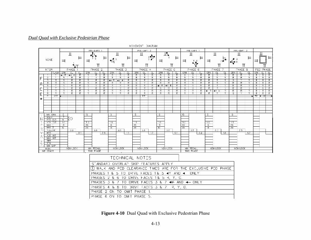
If it is determined through capacity analysis that dual-quad operation is required and an exclusive pedestrian phase is necessary, a "9-phase" operation is available. The pedestrian phase is serviced after the controller leaves the left-side barrier phases (1&5, 2&6). The pedestrian phase is shown on the signal plan as a separate phase; however, the Walk/Don’t Walk times are programmed into phase 1 of the controller.
An intersection with this type of “9-phase” sequence cannot be coordinated in a closed loop system. This is discussed in the Signal Systems section.

4-9
The signal indication displays for quad type phasing are shown on Figure 4-6 through Figure 4-10.
Quad (Protected/Permitted)
This phasing diagram shown below is placed on the bottom half of the signal plan to clarify
the sequence of phasing associated with this type of operation. In this example, the right-turn overlap is a non-standard overlap and requires special notes.
Figure 4-6 Quad (Protected/Permitted) and Phase Diagram

4-10
Quad (Protected Only)
The phasing diagram shown below is placed on the bottom half of the signal plan to clarify
the sequence of phasing associated with this type of operation.
Figure 4-7 Quad (Protected Only) and Phase Diagram

4-11
Dual Quad (Protected/Permitted)
This phasing diagram shown below is placed on the bottom half of the signal plan to clarify
the sequence of phasing associated with this type of operation.
Figure 4-8 Dual Quad (Protected/Permitted) and Phase Diagram

4-12
Dual Quad (Protected Only)
Figure 4-9 Dual Quad (Protected Only) and Phase Diagram
4-13
Dual Quad with Exclusive Pedestrian Phase
Figure 4-10 Dual Quad with Exclusive Pedestrian Phase

4-14
NEMA Ring Diagrams
The controller unit (CU) is specified to meet the National Electrical Manufacturers Association (NEMA) Standards TS2 (reference 10). Although the CU can be programmed to provide a variety of phasing configurations, the CT DOT uses four basic sequences shown in Figure 4-11, Figure 4-12, Figure 4-13, and Figure 4-14. Most intersections owned and maintained by the Department are designed as one of these. Typical phase assignments are as follows:
• Phase 1 is an artery left-turn phase.
• Phase 2 is an artery through phase.
• Phase 3 is for pedestrian phase or a side street left-turn phase.
• Phase 4 is a side street through phase.
• Phase 5 is an artery left-turn phase.
• Phase 6 is an artery through phase.
• Phase 7 is a side street left-turn phase.
• Phase 8 is a side street through phase.
1 2 3 4 5 6 7 8
Figure 4-11 NEMA Single Ring Diagram
Sequence #1: Single Ring Operation
This is the most common sequence. One phase is serviced at a time and must terminate before another becomes active.
Figure 4-12 NEMA Dual Ring, Quad/Sequential Diagram
Sequence #2: Dual Ring Operation, Quad / Sequential
This is the most common dual ring sequence. It is usually used for an arterial quad left-turn.
Ring #1
Ring #2
Right Side Barrier
Barrier
5 6
3 4 7 8 1 2
Left Side
4-15
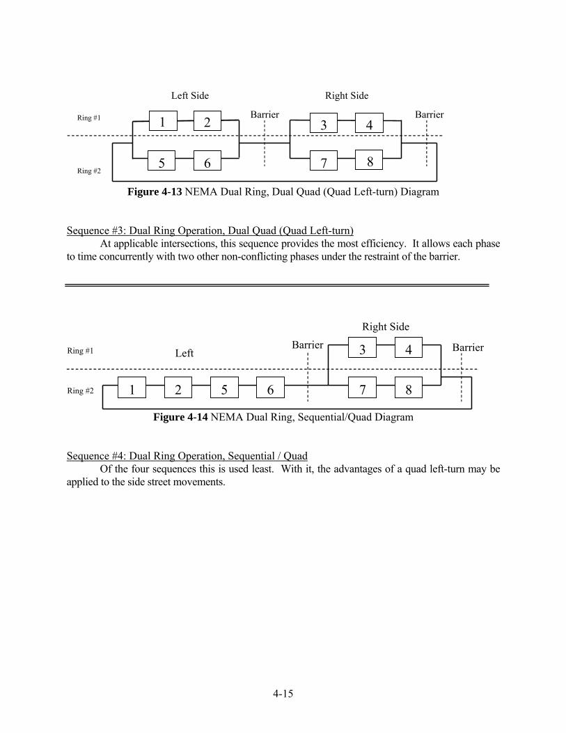
Figure 4-13 NEMA Dual Ring, Dual Quad (Quad Left-turn) Diagram
Sequence #3: Dual Ring Operation, Dual Quad (Quad Left-turn)
At applicable intersections, this sequence provides the most efficiency. It allows each phase to time concurrently with two other non-conflicting phases under the restraint of the barrier.
Figure 4-14 NEMA Dual Ring, Sequential/Quad Diagram
Sequence #4: Dual Ring Operation, Sequential / Quad
Of the four sequences this is used least. With it, the advantages of a quad left-turn may be applied to the side street movements.
Ring #1
Ring #2
Right Side
2
5 6
Left Side Barrier
3 4Barrier
87
1
Ring #1
Ring #2
1 2 5 6
3 4
7 8
Barrier Barrier Left
Right Side

4-16
Overlaps
NEMA Standard Publication TS2 (reference 10), Section 1.1.32 defines overlap as "A green indication that allows traffic movement during the green intervals of and clearance intervals between two or more phases". It is important to understand that an overlap is not a phase but rather a combination of phases. The green, yellow, red indications are driven by the Controller Unit (CU) overlap outputs rather than one of the standard eight phase outputs. The overlap outputs do not have detection inputs. An overlap green indication is extended whenever one of the parent phases is extended. The overlap clearance times are from the parent phase that is terminating. Walk movements cannot be overlapped. When overlaps are used, the clearances are shown on the plan as if no phases are skipped (all phases are called). The number of overlaps is not limited to four when using controllers meeting current specifications.
Overlaps are used in many ways such as a flashing sign clearance, an inside clearance or a pre-emption movement which is not in the normal sequence. The most common overlaps are advance approach and right-turn. An overlap is also used in the lag green phasing.
The advance approach (the through movement associated with an advance left-turn) and lag overlaps have been illustrated in previous left-turn sections and are usually standard overlaps.
The right-turn overlap is a phasing operation in which the right-turn movement of an approach has a green arrow and moves continuously through the phase clearances and/or concurrently with another phase such as a non-conflicting advance left-turn. Right-turn overlaps are usually non-standard. Right-turn overlaps should only be used when they are necessary due to a significant turning volume. The benefits of an overlap are to be weighed against the potential conflicts with pedestrians and other vehicles in the intersection area as well as downstream. Moving the right-turn volume in the overlap phase should reduce the green time needed for the side street. Also the intersection geometry must be conducive to allow the overlap feature. Separate turn lanes of adequate length, appropriate corner radii and proper lane width should be provided. In areas, which include medians, the potential conflict between U-turning vehicles and right-turning vehicles needs to be addressed. Although a continuous right-turn flow is generally desirable, right-turn-on-red can accommodate significant volumes without an overlap green arrow.
The placement and use of detectors for this type of operation deserves careful consideration, including a detailed analysis of turning volumes:
1. Detection can be provided for the artery left-turn lane and the side street right-turn lane. In many situations, this arrangement can result in lower side street green times and therefore, a higher g/c ratio for the artery.
2. Detectors can be provided for the artery left-turn lane only. This would then provide side street right-turns extra time to move and accommodate the side street right-turning traffic that was not handled by the side street phase.

4-17
In a standard overlap the green, yellow, red indications on the signal face are the same as the green, yellow, red overlap outputs from the CU. There are usually no arrows in the signal face driven by the overlap. The overlap clearance indications cannot be misinterpreted. Refer to Figure 4-15. The face 1 green arrow and yellow arrow are phase 1 outputs. The face 1 & 2 circular green, yellow, red is a standard overlap of phase 1 + 2. Technical notes to clarify the sequence are not needed. "Standard Overlap Skip Features Apply".
In a non-standard overlap, the green, yellow, red overlap outputs are altered by circuitry external to the CU to provide the sequence desired. Usually this happens with a right-turn arrow. The green arrow does not remain on during all phases of the overlap program. Occasionally the yellow and red indications are not displayed either. Refer to the right-turn overlap in the sequence below. The technical notes shown on Figure 4-15 are required to clarify the overlap clearance indications when a phase is skipped.
Figure 4-15 Technical Notes for a Non-Standard Overlap
5-1
5 CAPACITY ANALYSIS
Lost Time
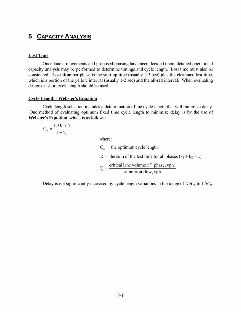
Once lane arrangements and proposed phasing have been decided upon, detailed operational capacity analysis may be performed to determine timings and cycle length. Lost time must also be considered. Lost time per phase is the start up time (usually 2-3 sec) plus the clearance lost time, which is a portion of the yellow interval (usually 1-2 sec) and the all-red interval. When evaluating designs, a short cycle length should be used.
Cycle Length - Webster's Equation
Cycle length selection includes a determination of the cycle length that will minimize delay. One method of evaluating optimum fixed time cycle length to minimize delay is by the use of Webster's Equation, which is as follows:
i
o YKC−+
=1
55.1
where:
=oC the optimum cycle length
=K the sum of the lost time for all phases (k1 + k2 +...)
vphflow, saturation
vph)phase, (i volumelane critical th
=iY
Delay is not significantly increased by cycle length variations in the range of .75Co to 1.5Co.

6-1
6 SIGNAL TIMING
Maximum Green
Traffic demand at the intersection is critical in determining the number of timing plans needed and the actual timings of the phases. If the peak hour flows are significantly greater than off peak and weekend volumes, more than one timing plan should be considered and the maximum green times should be based on the volume splits.
The maximum green interval limits the time a phase can hold the green. When the signal is properly timed with appropriately short vehicle extensions, the maximum green interval will not consistently time out unless the intersection is significantly over capacity. The maximum green interval is typically determined based on a detailed capacity analysis of the intersection. With actuated operation, a maximum green interval of 1.25 to 1.5 times the maximum green time calculated by capacity analysis is generally desirable. This will allow the signal to better react to variations in traffic demand thereby maximizing the efficiency of signal operation. A maximum green interval that is set too low can significantly reduce the benefit of actuated operation. It should be noted that when a signal is running coordinated in a signal system, other considerations (cycle length) may take precedence in determining maximum green times.
Minimum Green
For actuated phases, minimum green intervals should be enough to allow vehicles stopped between the detection point and the stop bar to get started and move into the intersection. Large presence detection or other circumstances may allow shorter settings and thus more efficient operation and increased capacity. Typical minimum green times to be used for various phases are as follows: arterial phase - 15", left-turn phase - 5" and side street phases – 5" to 9". The timing for an advance green interval (actuated or non-actuated) should not be less than 5 seconds.
Vehicle Extension
The passage time or vehicle extension is the time required for a vehicle to travel from the detector to the stop bar or to the adjacent detector where multiple detection exists. The vehicle extension is also the time required to accommodate the gaps between vehicles. For maximum efficiency the vehicle extension should be set as short as practical to retain the green only as long as a real and consistent demand is present, but should not service vehicles straying behind. However, where detectors are located at some distance from the stop bar, the vehicle extension must be long enough to permit the vehicle to travel from the detector to the intersection without gapping out (See section on Vehicle Detection).

6-2
Gap Reduction
Volume density features, such as gap reduction and variable initial may be utilized to provide a more efficient signal operation. Gap reduction can be used on any actuated approach to an intersection. If a short minimum time is used on a side street, a large vehicle extension time that is reduced over the duration of the phase can provide a snappy operation. This feature reduces the possibility of the phase gapping out when slow moving vehicles cross the detection area at the beginning of the phase. The controller settings that govern gap reduction are vehicle extension; time before reduction (TBR); time to reduce (TTR) and minimum gap (MIN GAP). The gap reduction feature occurs during the green interval of the phase.
Variable Initial
In areas where speeds are great and it is necessary to have detection a distance from the stop bar, the provision of an additional detector and/or use of the variable initial feature can reduce potentially long vehicle extension times and high minimum green settings. Variable initial allows the minimum green period to be increased depending upon the number of vehicle actuations stored in the related phase while its signal is displaying yellow or red. The minimum green time is increased only after the added initial time amounts to more than the minimum green time and is limited by the maximum initial time setting. In cases where the calculated maximum initial is not much higher than the minimum green, the use of a minimum green equal to the calculated maximum initial value in lieu of the variable initial feature may be acceptable.
The variable initial feature is generally associated with an actuated arterial phase. The following is an example showing how the values for the added initial (ADD INIT) and maximum initial (MAX INIT) settings are typically calculated. The added initial is expressed as seconds per actuation. If only the variable initial feature of volume density functions is used, the minimum gap should be programmed to equal the vehicle extension.
Example: Determine the added initial and maximum initial values for an arterial phase of a signal with operating speeds (85 th percentile) of 55 mph. Posted speed limit is 45 mph. The detection setback is 405 feet for the leading detector with an additional detector placed 2.5 seconds from the leading detector based on the posted speed limit. The additional detector is located 2.5 seconds x 45 mph (1.47) = 165 feet from the leading detector (240 feet from the stop bar).
• Determine the number of vehicles (N) which could store between the stop bar and the detector closest to the stop bar assuming an average length per vehicle of 25 feet. N = 240 ÷ 25 = 9.6 vehicles (use 10 vehicles).
• Determine the maximum initial setting (MAX INIT) which is the time needed to process the queue of vehicles stored between the stop bar and detector closest to the stop bar. MAX INIT = 3.7 + 2.1 (N) = 3.7 + 2.1 (10) = 24.7 seconds. This is based on studies that found the first vehicle had a starting delay of 3.7 seconds to enter the intersection with subsequent vehicles requiring an average of 2.1 seconds each.

6-3
• Calculate the added initial setting (ADD INIT). ADD INIT = (MAX INIT ÷ N) (d) ÷ 2 = (24.7 ÷ 10) (0.60) ÷ 2 = 0.7 seconds per actuation. “d” is the percent of arterial traffic on the higher volume approach during off-peak hours. For example, if directional distribution is 60/40 use d = 0.60. Note that in this example the calculation involves a division by two to account for the two detectors per lane on each artery approach. If the design included only one detector per lane on each artery approach, the calculation would not include a division by two.
For this example, say the normal minimum green is 15 seconds, and the ADD INIT (seconds per actuation) setting is 0.7. Only after the 22nd actuation (during yellow or red) when the sum is 15.4 seconds and thus exceeds the minimum green value of 15 seconds will the minimum green be lengthened. Each additional actuation will then lengthen the minimum green by 0.7 seconds up to the maximum initial setting.
Min/Max Timing Range (Town Signals)
In addition to actual signal settings, town signal plans require a minimum and maximum timing range for approval by the State Traffic Commission. This requires three columns of timings for GRN, CL1 & CL2. The minimum and maximum timing range for the GRN interval refer to the range from the shortest allowable minimum green to the longest maximum green. The minimum and maximum timing ranges for the WALK and DON’T WALK intervals of exclusive walk phases should be shown as indicated on Figure 16-2.
Clearance Intervals
Phase change intervals or clearance intervals usually consist of a yellow clearance interval followed by an all red clearance interval. The yellow interval is computed to provide adequate time to alert drivers of the need to stop for the forthcoming all red interval. An all red clearance interval is provided following the yellow interval to give drivers, which may be too near the intersection to stop, sufficient time to proceed safely through the intersection. Care should be taken to ensure that excessively long clearances do not result. Drivers may become accustomed to long clearances, particularly red intervals, and increased violation of the clearance interval may occur. The following is the current method to determine clearance intervals:
Conflict Points
A conflict point is the intersection of two vehicle paths. Critical conflict points occur at the intersection of the longest clearing distance from one approach and the shortest entering distance of an opposing approach.
Figure 6-1 shows the potential conflict points between two vehicles at four way intersections and some examples of critical conflict points for clearing vehicles at various approaches on multi-lane roadways.

6-4
Figure 6-1 Conflict Points
Potential critical conflict point for clearing vehicle x with entering vehicle/pedestrian (where x = 1, 2, 3, 4). * At locations with significant pedestrian activity, the path of a pedestrian should be considered an “entering vehicle”.

6-5
Yellow
Compute the yellow clearance interval for each phase using the following formula:
)22( AgaVtY+
+=
where: Y = Yellow clearance interval in seconds t = reaction time (use 1 second) V = 85% percentile approach speed in ft/sec or m/sec a = deceleration rate of a vehicle (use 10 ft/sec/sec or 3 m/sec/sec) A = Acceleration due to gravity (32.2 ft/sec/sec or 9.81 m/sec/sec) g = percent grade in decimal form (+ for upgrade, - for downgrade)
• Calculate the yellow clearance interval to the nearest 0.1 second.
• Do not use a yellow clearance interval of less than 3 seconds or (not normally) more than 5 seconds.
• Similar yellow clearance intervals for the artery should be considered in a system.
• In instances where the side street approach has a low minimum green, presence detection at the stop bar, and a low vehicle extension, it can be assumed that most approaching drivers on the side street are expecting to stop at the intersection. In that case, a yellow clearance interval of 3 seconds may be appropriate.
• In many situations, an approach speed of 25 mph can be assumed for left-turning vehicles.

6-6
Red
Compute the all red clearance interval for each phase using the following formula:
KTTR ec +−= where: R = all red clearance interval in seconds Tc = the clearing time, i.e. the time that the last vehicle of the clearing
stream takes to cover the clearance distance Dc in feet or meters, measured from the stop bar to the conflict point. (See Figure 6-1 for definition of conflict point). Tc = Dc ÷ Vc, where Vc = clearance speed (use speed limit in ft/sec or m/sec).
Te = the entering time, i.e. the time that the first vehicle of the entering stream of the next phase takes to cover the entering distance De in feet or meters, measured from the stop bar to the conflict point. Te = De ÷ Ve, where Ve = entrance speed (use 15 mph converted to ft/sec or m/sec, or adjust based on field observations).
K = the time that the last vehicle of the clearing stream takes to clear the conflict point, usually 1.0 second.
• Calculate the all red clearance interval to the nearest 0.1 second.
• The all red clearance interval should be a minimum of 0.5 seconds (for other than left-turn phases) unless engineering considerations indicate another value.
• Care should be taken when calculating the all red clearance intervals in coordinated traffic signal systems. Timings in these systems may be such that an entering motorist can correctly predict the onset of the green interval and thus get a "running" start through the intersection.
• For turning vehicles, the value of Vc should be based on field observations and be appropriate for existing geometry. Generally a value of 15 to 20 mph for turning vehicles can be used if information on observed vehicles is not available.
• For arterial protected/permitted left-turn phasing, an all red clearance interval of 0.1 seconds should be used so as not to violate driver expectancy.
• For non-arterial protected/permitted left-turn phasing, the all red clearance interval should be determined after a careful review of all possible phasing which may follow the left-turn phase. In many instances, an all red interval of 0.1 seconds is appropriate.
• For protected-only left-turn phasing the all red clearance interval should be calculated using the formula.

7-1
7 VEHICLE DETECTION
Controller Operation
Traffic control signals are usually described as pre-timed or vehicle actuated. Vehicle actuated controllers can be semi-actuated or full-actuated. In semi-actuated operation detectors are not provided for arterial through traffic and right of way is relinquished only when a call is received for an actuated phase. Full-actuated operation requires detectors on all approaches and right of way does not automatically go to a designated phase unless it is recalled by a function on the controller. The type of vehicle detection system used for actuated signal control depends on the operational requirements of the intersection and may be influenced by physical constraints (i.e. lack of right-of-way, poor pavement conditions, bridge structures, etc.). In addition, cost effectiveness should be considered. In general, all signals on state highways should be designed for full-actuated operation, unless the signal will be in a coordinated system in which "free" operation is not anticipated.
Controllers have three modes for detection memory: non-lock, lock and recall.
In the non-lock mode of memory, a waiting call is dropped by the controller as soon as the vehicle leaves the detection area. Non-lock detection memory is associated with large areas of detection at the stop bar. This type of operation can reduce delay by screening out false calls.
The lock feature means that a vehicle call is held by the controller (even after the vehicle has left the detection area) until the call has been satisfied. This type of detection memory is usually associated with point detection such as one 6 ft. X 6 ft. (1.8 m X 1.8 m) loop or a magnetic detector. This type of operation is incapable of screening out false calls.
The recall feature of a controller is a function that causes the automatic return of the right of way to a street. Minimum recall returns to the selected phase for the minimum amount of green time for that phase. This feature is used primarily for the artery phase of a full-actuated signal and for the phase in which the signal is expected to rest. Maximum recall returns to the selected phase for the maximum of green time for that phase. This feature is used primarily for fixed time advances and the artery phase of semi-actuated signals.
Detector Types
Traffic detectors are used to sense pedestrian or vehicular demand. The demand information is then provided to the controller. There are many types of detectors available. A brief description of some of the most common types follows.
Push button Push buttons are commonly used to detect pedestrian demand. Push button detection is not extendible.
Loop Loop detectors consist of an amplifier located in the controller cabinet and coiled wires in the pavement, which create a magnetic field. It is the most widely used type of vehicle detection because of the flexibility of design. Loop detectors can be used to sense vehicle presence, passage, lane occupancy, speed and volume.

7-2
Preformed Loop Operationally similar to the loop detector described previously. The preformed loop has the designed number of turns of wire encased in protective tubing; PVC, rubber, or cross linked polyethylene (XLPE). It is considered much more durable than sawcut and sealed loop detectors. The extra layer of protection allows the XLPE loop to be paved over with 450 degree Fahrenheit asphalt or be direct-buried in gravel or dirt roads. Applications: new pavement between base course and wearing course; attached to re-bar in concrete bridge deck; an approach unusually susceptible to pavement damage; temporary detection on a side street or driveway during construction.
Magnetic There are four types of magnetic detectors: the standard magnetic detector, directional magnetic detector (no longer available), magnetometer, and self-powered vehicle detector (SPVD). The standard magnetic detector cannot sense vehicles moving less that 5 mph and therefore cannot provide presence detection. The SPVD is similar to the magnetometer; however, it does not require cable to connect the sensor to the amplifier. The magnetometer and SPVD can provide either pulse or presence detection.
Pressure Vehicle pressure detectors are activated by the weight of a vehicle and consist of a metal frame and plates installed in the roadway. They were very reliable, but their use is now very limited due to high installation costs and resulting adverse pavement conditions.
Microwave (Radar) This method of detection uses Radar (Radio Detection and Ranging) to identify the presence of a vehicle. The microwave detector is essentially a radio frequency (RF) transmitter/receiver with frequency and power governed by the FCC. The microwave detector transmits a high frequency, low power signal to the desired detection zone. When a vehicle enters the detection zone some of the energy is reflected back to the microwave detector, which when processed, can provide volume, occupancy, speed, and classification data.
Video Video detection is an image processor. It consists of a microprocessor-based CPU and software that analyzes video images. Using a mouse and interactive graphics, the user places virtual "detectors" on the video image displayed on a monitor. Each detection zone emulates an inductive loop.
7-3
Loop Detector Mode/Features
Loop vehicle detectors have two modes of operation, presence and pulse. Presence mode is used for large areas of detection to register a vehicle's presence in a detection zone. As implied, the detector amplifier holds the output call as long as a vehicle is present in the detection zone. The controller may be set for either lock or non-lock memory with presence mode. Pulse mode is used to describe a detector that detects the passage of a vehicle by motion only (point detection). The detector amplifier provides a single output pulse when a vehicle enters the detection zone. Pulse mode is primarily used with single (non-segmented) loop detectors designated as system detectors that only provide vehicle count data. In most cases, this type of detector mode is associated with locking memory on the controller.
Loop vehicle detector amplifiers have delay and extend features available. By using the delay feature the call is output to the controller only if a vehicle is continuously detected beyond a preset time period (e.g. 8"). Once the controller is servicing the phase, the delay feature is inhibited. The delay feature is typically used to screen out false calls. By using the extend feature the call is held for a preset time after the vehicle leaves the detection zone. The extend feature can be used to allow a passing vehicle to reach a predetermined point beyond the detection zone before the call is terminated, without using a higher than desired vehicle extension. In the design of detection systems for actuated control it is necessary to select controller phase mode (lock, non-lock, min recall, max recall and ped recall), detector mode (presence and pulse) and detector feature (delay or extend). The delay and extend features are only available for use with the "presence" detection mode.
The following information has been developed to assist the engineer in the design of loop detection for actuated traffic signal control. These are guidelines only. Each intersection should be designed for its specific characteristics.

7-4
Detection Design Guidelines
Arterial Detection
When designing a signal as full actuated, the location of detection on the major street (arterial) will be dependent on the operating speeds of through traffic.
1. If speeds are 35 mph or greater (high-speed approaches), detection should be located 5 seconds from the stop bar based on the 85th percentile speed. One concern with this type of design is that drivers approaching a signal when the light turns yellow must make a decision whether to stop or go. There exists an indecision zone, commonly known as the "dilemma zone", defined as the range of distances from the stop bar, where the percentage of vehicles, which will stop, is between 10% and 90%. The designer should refer to the "dilemma zone" section which follows to ensure that proper dilemma zone protection is provided.
Generally it is desirable to provide an additional detector between the stop bar and the detector located 5 seconds (at the 85th percentile speed) from the stop bar. This application can be used to detect vehicles which may enter the arterial from roads, or drives between the stop bar and the leading detector. Providing a second detector also allows for a reduction in the vehicle extension. The additional detector should be placed 2.5 seconds from the leading detector based on the posted speed limit. This ensures that a vehicle traveling at the posted speed limit will reach the second detector prior to the signal gapping out. A "trap check" should be performed to verify that after leaving the trailing detector, vehicles traveling at the speed limit will be beyond the 10% lower dilemma zone limit at the onset of yellow.
The controller phase mode should be MIN RECALL and the detector mode PRESENCE.
See Figure 7-4 for placement of detectors.
2. If speeds are less than 35 mph (low speed approaches), detection should generally be located 3 to 4 seconds from the stop bar based on the 85th percentile speed. The problem of the driver being faced with indecision on whether to proceed through the intersection or stop is seldom an issue with speeds less than 35 mph.
The controller phase mode should be MIN RECALL and the detector mode PRESENCE.
See Figure 7-4 for placement of detectors.

7-5
Dilemma Zone
It has been the Department’s practice when designing a full-actuated signal to consider "dilemma zone" for isolated intersections. A commonly utilized technique is to locate the arterial detector 5 seconds from the stop bar based on the 85th percentile speed. Vehicle extension should be sufficient for a vehicle traveling at the posted speed limit to travel from the arterial detector to beyond the lower limit dilemma zone distance from the stop bar. This method of design was developed to ensure that vehicles traveling at the posted speed limit will not be "trapped" within the dilemma zone. However, it can create high minimum green and vehicle extension timings. The designer should consider techniques to reduce these settings, such as variable initial or a design utilizing two approach detectors.
Dilemma zone is defined as the range of distances from the stop bar, where the percentage of vehicles which will stop, at the onset of yellow, is between 10% and 90%. The standard method for avoiding trapped vehicles is to place a detector at the 90% point and allow these vehicles to extend the interval sufficiently to ensure that they pass the lower 10% limit prior to the onset of yellow.
The following table is from the Traffic Control Devices Handbook and lists those distances at which 10% and 90% of approaching vehicles are expected to stop for various speeds. Distance (Feet) Probability of Stopping Speed (MPH) 10% 90% 35 102 254 40 122 284 45 152 327 50 172 353 55 234 386
Note that the 90% point for all speeds is approximately 5 seconds of travel time. To ensure that vehicles are detected before they enter the dilemma zone, 5 seconds (at the 85th speed) should always be used in determining the arterial detector setback.
The following guidelines can be used to ensure dilemma zone protection:
1. Leading arterial detectors should be located 5 seconds from the stop bar based on the 85th percentile speeds. A 5-second vehicle extension should be used for the artery phase if a single detector per lane is utilized. If two artery detectors per lane are used, the vehicle extension should be set at 2.5 seconds.
2. Trailing arterial detectors (if used) should be placed 2.5 seconds from the leading detector based on the posted speed limit.
3. Perform a "trap check" to ensure vehicles traveling the speed limit will not be within the dilemma zone upon termination of artery green. For designs utilizing a single detector per lane, this is determined by subtracting the distance a vehicle traveling the speed limit will cover during the extension time (5 seconds) from the setback distance calculated for the 85th percentile speed. See Figure 7-1. For designs utilizing two detectors per lane, this is determined by subtracting the distance a vehicle traveling the speed limit will cover during the extension time (2.5 seconds) from the setback distance of the trailing detector. See Figure 7-2.

7-6
4. The difference should be less than the lower dilemma zone limit (see table) at the speed limit. Generally, slower vehicles will not be trapped if the posted speed limit and 85th percentile speed are within 15 mph of each other.
5. When a phase terminates at maximum time, dilemma zone protection will likely not be provided. Therefore, maximum green settings should be based on a careful consideration of capacity analysis, which balances the efficiency of signal operation with the safety benefits of dilemma zone protection.

7-7
Figure 7-1 Dilemma Zone Trap Check (One Detector)

7-8
Figure 7-2 Dilemma Zone Trap Check (Two Detectors)

7-9
Left-Turn Lane Detection
For left-turn lanes (Protected/Permitted and Protected Only Phasing), the detection zone should consist of a series of three loops, square or rectangular, with a typical longitudinal dimension of 6 feet (1.8 m). See Figure 7-4 for placement of detectors. The detectors should be spaced 8 feet (2.4 m) apart, beginning approximately 5 feet (1.5 m) in front of the stop bar. If there is an island or median the detection area should begin at the nose of the island or median. The detection zone should not end less than 25 feet (7.5 m) from the stop bar.
Set the controller phase mode on NON-LOCK and the detector mode to PRESENCE.
For left-turn detection zones that cannot be designed within the preceding guidelines because of extenuating circumstances (e.g. interference from a bridge deck), consider using one loop set 25 feet (7.5 m) from the stop bar.
Set the controller phase mode on LOCK and the detector mode to PULSE.
In lieu of a fixed advance or lag green without an exclusive left-turn lane, consider installing a loop detector such that the wheel path of the left-turning vehicle will actuate and extend the left-turn phase. Add a technical note "Detector D1 to only extend phase 1." See Figure 7-3.
Set the controller phase mode on MIN RECALL and the detector mode to PRESENCE.
Figure 7-3 Left-Turn Lane Detection

7-10
Sidestreet Detection
In general, sidestreet detection should be provided to cover the desired detection zone adjacent to the stop bar. For through lanes, single lane approaches, and right-turn lanes the recommended detection zone should begin no closer than 10 feet (3.0 m) from the adjacent road’s curbline extension and end not less than 25 feet (7.5 m) from the stop bar. Generally, three segmented loops per lane will provide an adequate area of detection. Each loop should be square or rectangular with a longitudinal dimension of 6 feet (1.8 m). See Figure 7-4 for placement of detectors. The longitudinal spacing between loops should be 8 feet (2.4 m).
The controller phase mode should be NON-LOCK and the detector mode PRESENCE.
In cases where stop bars are set back from the extended curb line or where non-lock/presence detection cannot be designed within the guidelines noted above, a single loop centered in the travel lane should be used. The loop should be square or rectangular with a longitudinal dimension of 6 feet (1.8 m) and it should be located 25 feet (7.5 m) from the stop bar. See Figure 7-4 for placement of detectors. It should be noted, that the presence of a "No Turn on Red" sign is not, of itself, justification for a single loop, "lock" mode design.
The controller phase mode should be LOCK and the detector mode PRESENCE.
System Detection
The Department uses loop detectors for interconnect system detectors. A discussion and placement guidelines are in the Signal System section of this manual.
Miscellaneous
1. The rear loop of a multi loop approach may be used as a system detector to obtain volume counts in a closed loop system; however, the length must be 6 feet (1.8 m) to obtain accurate counts.
2. Installation of detectors in crosswalks should be avoided.
3. Consider using gap reduction at isolated intersections with relatively equal volumes on all approaches and where capacity is of concern.
4. Loop detectors are the most commonly used type of detector. They should be square or rectangular with a typical longitudinal dimension (length) equal to 6 feet (1.8 m). The other dimension (width) should be determined based on lane width. The detector should be sized so that it is centered in the lane and 3 feet (0.9 m) off each adjacent centerline, lane line, or edge line/curb line. For lanes less than 12 feet wide, the detectors should be 6 feet wide and centered in the lane. In general, a loop detector should not extend across more than one lane. The size of loop detectors, as shown on signal plans, should be denoted as Width X Length.
5. Engineers should be familiar with Chapter 5 "Detectors" in the Traffic Control Systems Handbook (reference 15), prior to determining the phase mode and detector location.

7-11
6. Detector numbers should correspond to the appropriate signal phase where possible. On approaches with two detectors for dilemma zone protection, each detector should be identified by a unique number (for example D2, D2A, D2B, and D2C).
7. On approaches with wide throat areas and where "right-turn on red" is prohibited, consider installing loops in a configuration to ensure right-turning vehicles are adequately detected.

7-12
Loop Detector Placement
Figure 7-4 Loop Detector Placement
7-13
Microwave Detection Guidelines
There are currently two types of microwave detectors available. The continuous wave (CW) and the frequency modulated continuous wave (FMCW). The CW type only detects vehicles that are moving, not providing true presence. The FMCW type detects vehicles that are motionless as well as moving. These are used extensively on the interstate Intelligent Transportation System. For local intersection control, the Department specifies the CW which is easier to install and maintain but has limited features as described below.
Characteristics
• The microwave detector is directional. It may be set for either approaching or departing vehicles. If set to detect approaching vehicles it will exclude departing vehicles.
• The cone of detection is approximately 30 degrees.
• The range is 25 feet (7.5 m) to 150 feet (46 m).
• The minimum detection speed is normally 5 to 5-1/2 mph (8 to 8.8 kph).
• The call will be held as long as the vehicle is moving within the detection zone.
• True presence detection mode, delay, and extend features are not available.
Placement
The microwave detector should be fixed-mounted to a support structure (span pole or mast arm assembly) or a tall pedestal. Although the detector may be attached to a span wire, this is discouraged. Under windy conditions the movement of the span wire may create false calls and/or change the preset detection zone. There should be an unobstructed line of sight to the area of detection. The most desirable location is in front and above the approaching vehicle. The recommended mounting height is between 15 feet (4.6 m) and 24 feet (7.3 m).
Microwave detection is a non-intrusive method and is less expensive than loop detection; however because of the restrictions on placement and lack of presence detection it is usually used on an approach where loop detectors cannot be installed. The area of detection is usually shown as a shaded 30 degree cone aimed at the approach rather than rectangular symbols. Since microwave detectors cannot provide true presence detection, the phase must be on lock.

7-14
Special Application
Because of right-of-way restrictions, poor road conditions, or a bridge deck, it may be necessary to have microwave detection on one approach and loop detection on another approach of the same phase. If a microwave detector is to be used in conjunction with loops, the traffic engineer may want to use two consecutive phases to get a presence, non-lock operation on the loop detected approach. The first phase (parent) is set in non-lock mode and will be called and extended by both the loops and the microwave detector. The following phase (dummy) is set in lock mode and will also be called (but not extended) by the microwave detector. The first phase is programmed with the green timings and the yellow clearance. The dummy phase always follows and the combined green, yellow, red phase timings serve as the red clearance to the parent phase. The following are examples of technical notes required to clarify the intended operation:
1. Phase 5 (the dummy phase) CHECK to call Phase 4 (the parent phase). 2. D5 (microwave detector) to call Phase 4 and Phase 5 but only extend Phase 4. 3. Phase 4 ON to call phase 5.
Note: If pre-emption is present, an alternate red clearance may be needed.
Video Detection Guidelines
Like microwave, video is a non-intrusive detection technology. The video image detection system (commonly referred to as VIDS) consists of a camera for each approach and an image processor. The camera is fixed mounted, usually on a far-side mast arm assembly or a steel pole. It is located to feed an image of the approach to the processor. Detection zones are then superimposed on the image. The processor senses movement within the zone and then outputs a call to the controller unit. The processor may be programmed to provide outputs which emulate a loop detection system (pulse, presence, delay & extend). If desired the processor will accumulate data such as volume, occupancy, speed, and vehicle classification.
Video detection has been available since the late 1980’s. A search of the Internet for "video detection" will find many manufacturers and studies on the system. When evaluated against other detection methods several advantages and disadvantages are identified.
Advantages
• Detection zones may be easily adjusted to fine tune an intersection or to accommodate temporary signalization.
• Installation and maintenance does not depend on good pavement conditions or an easement on private property.
Disadvantages
• Camera location is crucial for effective operation and is discussed below.
• Accuracy degradation under certain conditions such as: congested conditions (slow moving traffic with a 5 minute average speed below 30 mph); low visibility (transitional lighting [dusk/dawn], rain, fog, snow); low vehicle to pavement contrast.

7-15
Until recently the price was much greater than a comparable loop detection system. If a VIDS is used on an approach that has multiple detection zones the cost may be less than loop detection which requires trenching, conduit, handholes, sawcut as well as the amplifiers.
Camera Placement
The camera location is critical for a VIDS. There should be an unobstructed line of sight to the area of detection. The most desirable location is in front of the approaching vehicle as high as possible. A camera mounted low and/or at an angle to the approach will create a detection zone image that may be obstructed by adjacent lane vehicles (especially trucks) which is known as cross-lane occlusion.
The recommended mounting height is 30 to 40 feet ± (10 to 12 m). The suggested rule is a 1 to 10 ratio of mounting height to distance to the detection zone. A low mounting height (such as on a mast arm) may introduce operational concerns. Road spray or truck exhaust may collect on the lens. Down-lane occlusion of vehicles in a distant detection zone may occur. The rising and setting sun may interfere with the image during certain months of the year.
The detection zone is shown as a rectangular area not segmented or restricted by 6 feet (1.8 m) length. Detection zones can be whatever length X width that is desired. As mentioned before, the designer must consider the direction of the camera in relation to the rising and setting sun. Also whether the approach is on a grade may affect the detection zone image. The controller phase may be on non-lock, lock or min recall.
8-1
8 FLASHING OPERATION
Programmed Flash
The controller should start up in the phase which has indications that flash yellow during flash operation. This is normally the arterial phase (phase 2). If a signal flashes all red, the controller should start up in the arterial phase, which again is usually phase 2.
As a fuel conservation measure, traffic signals may be placed on programmed flashing operation during those hours when volume warrants are not satisfied if the following conditions are met:
• The artery normally displays a flashing yellow during flash.
• There are no sight line restrictions from the side streets.
• No special feature (such as railroad pre-emption, drawbridge, etc) of the signal requires continuous operation.
Traffic signals that flash all red should not be placed on programmed flash. Stopping all vehicles all the time does not conserve fuel.
Maintenance Level
Traffic signal maintenance level is based on safety and operational considerations. Restricted sightlines from the side streets, unusual geometry/phasing and high traffic volumes during hours outside normal maintenance periods may be, alone or in combination, justification for an elevated level. The maintenance level for new signals will be determined by the Division of Traffic Engineering. Any recommendation for a change to the maintenance level of an existing signal will be reviewed by the Division of Traffic Engineering, the Office of Maintenance and the Office of Highway Operations. On consultant designs, the maintenance level will be provided to the consultant engineer by the Division of Traffic Engineering.
Level 1 24 Hours, daily. Example: Traffic signal that has railroad pre-emption. Level 2 Priority, 4 AM to 8 PM, daily. Example: Traffic signal on a commuter route. Level 3 Priority, 8 AM to 8 PM, daily. Example: Traffic signal at a shopping center. Level 4 Seasonal, same as level 2 from Memorial Day to Labor Day. Example: Signals
along primary recreational routes. Level 5 Normal, 8 AM to 4 PM, Monday through Friday.

9-1
9 PRE-EMPTION
Pre-emption is a feature used to modify the operation of a traffic control signal to grant right of way to emergency vehicles, trains or a specific traffic movement to meet a special need. This can be accomplished by modifying timing, sequence or display. When a pre-emption sequence is provided, special timings (i.e. clearance intervals, alternative minimum green time, etc.) will be required. Pedestrian walk and clearance intervals may be shortened or eliminated in order to provide a quick transition to the railroad track clearance display. In addition, the designer must specify how the signal returns to normal operation after the pre-emption sequence is completed.
Federal/State funds allocated for a State owned traffic signal upgrade will not be used to upgrade an associated town owned EVPS. All costs for the upgrade of existing pre-emption equipment are the responsibility of the town. Federal/State funds may be used to relocate the existing pre-emption equipment to the upgraded traffic signal if the town desires. A specification has been developed by the Department for this work and is available to the designer.
Emergency Vehicle Pre-Emption
In accordance with the Departments Policy No. E & H.O.-16, the State permits a municipality to pre-empt State maintained traffic signals. Funding for the initial installation of an EVPS is described in this policy and also in the section on Signal Ownership and Maintenance. All equipment necessary for pre-emption but not essential for normal intersection control is owned and maintained by the municipality. This includes, but is not limited to, the optical detector, RF receiver, phase selector and auxiliary equipment cabinet. This cabinet is required to allow accessibility by the Town without entering the State owned controller cabinet. There are a maximum number of six separate pre-emption movements available.
The emergency vehicle pre-emption system (EVPS) causes the traffic signal controller to advance to, and/or hold a desired traffic signal pre-emption phase. Some methods used to activate emergency vehicle pre-emption are coded light transmissions, hardwire, radio signals and siren. They require a controller that has the internal pre-emption capability and are described below.
System Types
Coded Light (Optical)
This system employs optical communication to identify the presence of a designated emergency vehicle (such as fire apparatus). Several components comprise the system. There is an optical emitter which is a high-intensity electronic (strobe) light mounted on the emergency vehicle. An optical detector is also provided. It is a directional electronic device which "sees" the coded signal from the emitter on the emergency vehicle from a distance up to 1800 feet (550 m). The third component is a phase selector. This electronic unit is interfaced with the traffic signal controller. The unit receives the pre-emption call from the detector and sends the command to the controller, which engages pre-emption.

9-2
Hardwire
This system employs a physical connection to identify the presence of designated emergency vehicle(s). The system requires a cable from the controller to an activation switch. The switch is located at the source of a pre-emption call (such as a fire station). Railroad Pre-Emption also uses this method with the exception that it uses an energized electrical loop with power sent and returned through a set of relays, and is subsequently discussed in this manual.
Radio
This system employs a radio frequency (RF) signal to initiate the pre-emption sequence. The pre-emption command may be transmitted over a narrowband system or over a wideband system which is called spread spectrum. In the narrowband system the signal is sent directly from the fire station to a receiver at the controller cabinet through the fire departments existing RF system. A direct line-of-sight is not needed with a narrowband system. A Town-owned receiver at the controller is required. The Spread Spectrum technology may also be used. Although the capabilities of an RF communication system are far more than necessary for pre-emption activation, it may be economical where it would be costly or impractical to install hardwire (such as over a movable bridge or a RR right-of-way). A direct line-of-sight is preferable with a spread spectrum system, however may not be necessary. A transmitter and receiver(s) are required to complete the system.
Siren
This system employs the emergency vehicle’s siren to identify the presence of an emergency vehicle. Directional microphones detect when and from which direction an emergency vehicle approaches an intersection. The system is adjustable for vehicle range and also for audible signature, such as yelp, wail, and high-low. This system detects all federally-approved Class A sirens eliminating the need for a transmitter on each vehicle.
Emergency Vehicle Pre-emption Design Guidelines
1. The design will be for primary response routes only. If not already on file, a map of the town indicating the location of all fire houses, all signalized intersections, and the primary response routes must be submitted to the Division of Traffic Engineering by the town. This map will be stored in Unit 1406 (Electrical).
2. The Town should be contacted regarding the inclusion, funding, and design of the EVPS for new signals or major revisions. Emitters are provided for major fire apparatus only.
9-3
3. Pre-emption confirmation lights (CL) are generally not allowed on state owned traffic signals. A special condition may warrant a CL such as a fire route from a one-way street that does not have signal indications. Confirmation lights are typically not included in State owned traffic signals because in the event of an equipment malfunction the confirmation light could mislead the emergency vehicle operator. A confirmation light may be included in the EVPS of a Town owned traffic signal.
4. The signal phase(s) associated with the pre-emption movement will be labeled "PRE-EMPT" along with a number, which indicates the priority level. For example, a #1 is the highest priority followed by 2, 3 etc.
5. If the desired pre-emption phase is exactly the same as a normal phase in the sequence, that phase should be designated the hold phase.
6. If the desired pre-emption phase is not exactly the same as a normal phase, a separate phase must be added to the movement diagram and designated the hold phase (e.g. phase 8). The phase will be serviced only during the pre-emption movement. The mode should be On/Omit. This prevents the phase from being serviced after initialization or during manual operation. The hold green (minimum green), yellow and red timings are shown in the phase as well as in the pre-emption settings block.
7. When a sequence that contains a non-standard overlap (e.g. right-turn arrow) is pre-empted, skipped phases may occur and produce incorrect clearance indications. The designer should review all possible clearance displays when entering the pre-emption phase and add appropriate technical notes.
8. When a sequence that contains a dummy phase (e.g. flashing sign clearance) is pre-empted, the designer should consider the effects if and when the dummy phase is skipped. In these cases, the Signal Lab should be contacted (860-258-0347) to discuss the various possible impacts a pre-emption call could have on the overall signal sequence.
9. Settings and interval timings for all pre-emption movements shall be listed in the pre-emption settings block on the traffic signal plan. All the pre-emption data which will be programmed in the controller must be provided in this block. See Figure 9-1.
10. On the traffic signal plan add the technical note "Pre-Emption to be Inoperative During Flashing Operation".
11. If the traffic signal is maintained by the state and has EVPS, add the note "Emergency Vehicle Pre-Emption Equipment to be Owned and Maintained by the Town of (list town)" to the signal plan.
12. The town will be required to provide maintenance on all pre-emption equipment outside of the traffic controller cabinet.
13. Countdown pedestrian indications are allowed on Town owned signals. They cannot be used at a signal where multiple pedestrian movements are overlapped. In these cases the pedestrian clearance times may vary, giving inconsistent countdown times. At locations with countdown pedestrian indications in use, the pedestrian clearance interval shall not be allowed to be shortened for emergency vehicle pre-emption.

9-4
Sample Pre-emption Settings Block
Railroad Emergency Vehicle
Ramp
PRE-EMPT 1 PRE-EMPT 2 (1) PRE-EMPT 3 (1) PRIORITY YES NO NO DET LOCK YES YES YES DELAY 0 0 0 ALT MIN GRN 0 (2) 5 5 ALT YELLOW Parent Parent Parent ALT RED Parent Parent Parent ALT PED CLR NO (3) (4) (4)
TRACK CLR GRN 15 N/A N/ATRACK CLR YLW 3.0 N/A N/ATRACK CLR RED 2.0 N/A N/A
(5)
TRACK CLR PHASE 7 N/A N/A HOLD GREEN 10 15 (6) HOLD YELLOW 3.0 3.0 3.0 HOLD RED 2.0 2.0 2.0 HOLD PHASE 8 2 4 EXIT PHASE 1 4 4 EXIT CALL None None None
(Column headings and settings are for illustrative purpose only)
(1) For locations which do not have railroad pre-emption, the emergency vehicle pre-emption settings are programmed in PRE-EMPT 1. If there is only ramp pre-emption, it is programmed as PRE-EMPT 1.
(2) Determined on a case by case basis. Normally set at zero but can be greater based on vehicle approach speeds.
(3) ALT PED CLR normally not provided, however in cases with handicap/elderly crosswalks or high speed roadways may be considered.
(4) Select the actual pedestrian clearance time if there is an exclusive pedestrian phase, a concurrent pedestrian phase with walk/don’t walk indications or a case where the pedestrian clearance time is used to operate a Stop Ahead sign.
(5) When the signal is to hold in the track clearance phase for pre-emption, these intervals can be deleted and timings can be inserted in the hold timing blocks.
(6) Sufficient time to clear the queue.
Figure 9-1 Sample Pre-emption Settings Block

9-5
Railroad Pre-Emption
Care should be taken when designing a traffic signal which is adjacent to a railroad crossing to preclude the possibility of a vehicle being trapped on the tracks. The method of actuation should be designed with adequate "Fail - Safe" features (a normally energized loop between the traffic signal control box and the railroad control box through a set of relays). Where crossings are 200 ft. (60 m) or less from a signalized intersection, railroad pre-emption will usually be required. At signalized intersections where the rail crossing is greater than 200 feet (60 m), but high vehicular volumes are expected, a queue analysis should be conducted to ascertain if pre-emption is required. Contact the Division of Traffic Engineering's railroad grade crossing section to determine extent of controls. Track circuit timings are developed by the Division of Traffic Engineering's railroad grade crossing section and track circuit designs are normally provided by the operating railroad.
Railroad Pre-emption Design Guidelines
1. Clearance out of normal operation to pre-emption shall follow ConnDOT traffic controller specifications.
2. Railroad pre-emption will require the use of a menu driven controller with internal pre-emption which will go directly into the pre-emption phase(s) which includes clearances.
3. Contact the Division of Traffic Engineering’s railroad grade crossing section during the preliminary design to determine how pre-emption will be provided and what special requirements must be shown on the plan.
4. The actual sequence and signal displays for railroad pre-emption must be approved by the Division of Traffic Engineering’s Electrical Unit and railroad grade crossing section; and the Department of Transportation’s Signal Maintenance Lab.
3. Railroad pre-emption consists of two separate traffic control device actuations. When the train hits the approach circuit the first actuation is to the traffic signal controller, which immediately advances the sequence to the track clearance phase, via controller internal pre-emption. After a pre-determined period, the second actuation is to the railroad warning devices, which must operate for 29 seconds prior to the train entering the crossing. The traffic signal track clearance time, to enable vehicles to move off the tracks, must be complete prior to the activation of the railroad warning devices. The total track circuit time required is the traffic signal track clearance time, plus the 29 second railroad warning device timing.
4. Depending on the type and class of rail line, two different types of train operations can occur at a grade crossing. The first is a through move (traversing the crossing non-stop), and the second is a stop and protect (the train must come to a stop for a pre-determined time period before proceeding over the crossing). For stop and protect crossings controlled by a traffic signal, the controller is to provide 29 seconds of all-red clearance and way side signals shall be provided for the train which shall be part of the traffic signal operations.

9-6
5. Traffic signals containing railroad pre-emption will normally not be allowed to be placed on programmed flash. A technical note indicating that the "signal shall not be placed on programmed flash" should be added to the plan.
6. When a railroad crossing is located on the side street leg of a signalized intersection, the emergency flash or fail-safe flash should be all red. This will provide gaps in artery traffic for side street vehicles to clear off the railroad crossing.
7. Separate pre-emption sequences for pre-emption during fail-safe flash or emergency flash may be required depending on site conditions.
8. Traffic signals containing railroad pre-emption should be placed on Maintenance Level 1 (24-hour).
9. A railroad pre-emption track circuit timing block should be shown on the roadway portion of the signal plan. Railroad device operational notes should be added directly adjacent to the track circuit timing block describing the operation during normal and manual operation and the operation during flashing operation. See Figure 9-2.
10. A construction note should appear on the signal plan stating that the signal installer must coordinate with the operating railroad the installation of the pre-emption interconnect cable from the traffic signal control box to the railroad control box. Adjustments of the existing railroad track circuit and/or warning devices may be required depending on the railroad pre-empt design.
11. The pre-emption phase will be labeled "PRE-EMPT" along with a number, which indicates the priority level. For example a #1 is the highest priority followed by 2, 3 etc. Railroad pre-emption (if present) is always labeled as pre-empt number 1.
12. If the desired pre-emption phase is exactly the same as a normal phase in the sequence, that phase should be designated the railroad hold phase. If an illuminated turn restriction sign is required to be on during railroad pre-emption, but will not be on during normal operation then the pre-emption phase is not considered to be exactly the same.
13. If the desired pre-emption phase is not exactly the same as a normal phase, a separate phase must be added to the movement diagram and designated the hold phase (e.g. phase 8). The phase will be serviced only during the pre-emption movement. The mode should be On/Omit. This prevents the phase from being serviced after initialization or during manual operation. The hold green, yellow and red timings are shown in the phase as well as in the pre-emption settings block.
14. The use of non-standard overlaps (e.g. right-turn arrow) and dummy phases should be avoided in the sequence of a traffic signal that has railroad pre-emption. Incorrect clearance indications may be displayed and interval times may vary, which could violate the track circuit time requirements. Because any phase may be skipped, the designer should review all possible clearance displays when entering the pre-emption phase.
15. Settings and interval timings for all pre-emption movements shall be listed in the pre-emption settings block on the traffic signal plan. All the pre-emption data which will be programmed in the controller must be provided in this block. See Figure 9-1.

9-7
16. For railroad pre-emption a track clearance phase is usually required. This phase will be serviced immediately and will time the track clearance green, yellow and red intervals prior to the controller transferring to the railroad pre-emption hold phase (unless the track clearance phase is the railroad pre-emption hold phase). The track clearance settings and hold phase settings must be entered into Pre-empt 1. See Figure 9-1.
17. Some signals have provisions for pre-emption from fail safe flash and emergency flash, therefore the need for the technical note – "Pre-Emption to be Inoperative During Flash Operation" will be determined on a case by case basis.
18. The Department of Transportation will maintain railroad pre-emption equipment housed in the traffic control cabinet and also the cable, conduit, etc. up to the railroad control cabinet on State maintained traffic signals. The railroad maintains the track circuit and all the equipment in the railroad control cabinet.
19. Countdown pedestrian indications are allowed on Town owned signals. They cannot be used at a signal with railroad pre-emption or at a signal where multiple pedestrian movements are overlapped. In these cases the pedestrian clearance times may vary, giving inconsistent countdown times.
Railroad Pre-emption Track Circuit Timing Block
NOTE:
WHEN A PRE-EMPTION CALL IS RECEIVED DURING NORMAL OPERATION OR MANUAL OPERATION RAILROAD FLASHING LIGHTS WILL COMMENCE OPERATION __ TO __ SECONDS INTO PHASE _ DEPENDING UPON WHICH INTERVAL CONTROLLER IS IN WHEN RAILROAD PRE-EMPTION CALL IS RECEIVED. WHEN PRE-EMPTION OCCURS DURING EMERGENCY FLASH OR FAIL-SAFE FLASHING OPERATION, RAILROAD FLASHING LIGHTS WILL COMMENCE OPERATION__ SECONDS AFTER THE RAILROAD PRE-EMPTION CALL IS RECEIVED.
TIME EVENTSTART OF TRAFFIC SIGNAL PRE-EMPTIONSTART OF RAILROAD FLASHING LIGHTS AND BELLSRAILROAD GATES START TO DROPRAILROAD GATES HORIZONTALTRAIN ENTERS THE CROSSING
RAILROAD PRE-EMPTION
(Timings and Phase numbers to be entered in the railroad device operation notes and circuit timing block are to be determined for each specific location by the Division of Traffic Engineering’s railroad liaison.)
Figure 9-2 Railroad Pre-emption Track Circuit Timing Block

9-8
Ramp Pre-emption
An expressway exit ramp may require a pre-emption movement to prevent the queue of exiting vehicles from backing up to the expressway mainline. A vehicle detector can be placed on the ramp to sense the presence of stopped vehicles and initiate the pre-emption movement which will hold in the ramp phase. Ramp pre-emption will invariably disrupt the normal signal operation possibly creating an arterial back-up as well. Any coordination with adjacent signals will also be interrupted. The designer should try to anticipate any adverse effects pre-emption will create. Inclusion of ramp pre-emption in the signal design should be judicious and only used when alternative measures have failed to address the situation. Other methods to prevent a back-up should be considered. These include, but are not limited to switching to a higher maximum green setting for the ramp phase, reducing the overall signal cycle length, utilizing volume density controller features such as TBR and TTR, providing an additional travel lane, or allowing right-turn on red. Ramp back-ups attributable to scheduled special events are generally handled more efficiently with police manual control rather than a ramp pre-emption system.
Ramp Pre-emption Design Guidelines
1. The design should be on a case-by-case basis. Each intersection may have unique
characteristics that dictate the pre-emption settings. A ramp on an upgrade will move vehicles slower than a ramp on a downgrade. Adjacent intersections may also require pre-emption to clear the vehicles leaving the intersection.
2. The size and location of the detector area is critical for effective pre-emption. The loop
should be long enough (typically 8 to 10 feet) so that a gap between two stopped vehicles does not cause the pre-emption call to be missed. The loop should be located far enough back to prevent unnecessary calls from vehicles that would normally clear during the phase green. The loop should be located close enough to accommodate ramp queues which will continue to build after the pre-emption detector is actuated. In determining the proper location for ramp detectors, the designer must consider the vehicle arrival rate on the off ramp and account for vehicles which will continue to accumulate at the back of the queue during the detector delay time, during the clearance interval for the signal phase being pre-empted, and during the time it takes for the last vehicle in the queue to start moving after the onset of green for the pre-emption phase.
3. A 10 to 12 second delay will typically prevent unnecessary false calls from slow moving
vehicles or from a series of staggered vehicles on a two lane ramp. The delay feature of the loop detector amplifier should be used rather than a pre-emption setting.
4. When ramp pre-emption is used at locations which have EVPS, the designer must determine,
in consultation with local officials, which pre-emption will have the higher priority. 5. The hold green time should be sufficient to clear the queue and enough vehicles to prevent
successive pre-emption calls. If not set high enough, the pre-emption movement may prematurely terminate during a gap in the queue.

9-9
6. The ramp phase may also be designated as the exit phase. When the pre-emption movement terminates, the local detectors will extend the green as needed and therefore a lower hold green time may be used.
7. When the ramp signal is coordinated with other signals the designer must consider the
effects of pre-emption on the system as well as the ramp. Also, if the intersection double-cycles, the ramp phase will have an excessive red time, creating another back-up, another pre-emption call, and another double cycle.
The above guidelines are written specifically to address queues on a signalized expressway
off-ramp however the concepts can also apply to other situations where limiting the maximum queue length at a signalized location is critical to safe operation.

9-10
Pre-Emption Definitions
Confirmation Light In an EVPS, the confirmation light provides a visual feedback to the emergency vehicle
operator confirming the traffic signal is in a pre-emption movement. It is mounted in a conspicuous location such as high on a steel pole or on a mast arm assembly. A confirmation light may be used in railroad pre-emption also. At locations where pre-emption is frequent and/or false calls occur it provides a visual confirmation to DOT maintenance personnel. In this case it is mounted on top of the traffic control cabinet.
Parent Phase For the purposes of pre-emption, it is the phase the controller is in when a call for pre-
emption is received.
Pre-emption Movement (Pre-Emption Run) A pre-emption movement is a series of intervals that provide the desired pre-emption
sequence. Normal operation such as phase timing, vehicle detection, and coordination is suspended until the movement criteria are satisfied. A movement may consist of clearance intervals into and out of a pre-emption green. It also may consist of more than one phase such as phases 1 & 6 in a quad or a track clearance phase prior the hold phase.
Primary Response Route The primary response route is the most common route taken by major fire apparatus from the
fire station. The primary response route and the major fire apparatus are designated by the town when the fire run map is submitted.
Track Circuit (Approach Circuit) The track circuit is a low voltage electrical system which senses the presence of an
approaching train. The tracks and the train are used to complete the circuit. It is designed, owned and maintained by the railroad company. The length of the track circuit depends on the track clearance time needed, the railroad device warning time and the speed of the train.
Track Circuit Time The total time needed to safely clear vehicles from the tracks and to activate and set the
railroad warning devices (lights, bells, and gates) prior to the train entering the crossing. The track clearance time and railroad device warning time determines the length of the track circuit.
Track Clearance Time The time needed to safely clear vehicles from the tracks. It is intersection specific and is programmed in the pre-emption settings as track clearance green, track clearance yellow and
track clearance red.
Way Side Signal Traffic signal head(s) located adjacent to the railroad right-of-way, facing the approaching
train. Prior to the activation of pre-emption this signal is red. When the traffic signal is pre-empted and has completed the required track clearance and railroad warning times, the signal head facing the train will turn green authorizing the train to proceed over the crossing.

9-11
Pre-Emption Settings Definitions
Priority (yes/no) When set to yes, a pre-emption call will override all other pre-emption calls (regardless of
priority number). Railroad pre-emption is always yes. All other pre-emption movements are set to no and priority is determined by its number.
Detector Lock (yes/no) If yes, a call that is dropped before the pre-emption movement begins will still be serviced.
If no, a call that is dropped (for example, during a delay time or during a higher priority pre-emption) will not be serviced. To ensure the pre-emption sequence occurs when called, it is recommended to set Detector Lock to yes.
Delay (seconds) The time between when the pre-emption call is received and the start of the pre-emption
movement. Usually used with hardwire pre-emption where the emergency station is a distance from the signal. Typically a "zero" setting is used with optical or siren pre-emption.
Alternate Minimum Green (seconds) The time for a green interval which is timing when pre-emption begins. For example, if the
controller is 2 seconds into a green interval and the Alt. Min. Green is 5 seconds, then when pre-emption begins, the green will time down for 3 more seconds. Typical values would be 5 seconds for EVPS and 0 seconds for Railroad. Note - The setting selected will apply to all phases being pre-empted.
Alternate Yellow (seconds) The interval time for yellow which is timing when pre-emption begins. Parent can be
selected to time down the yellow value in the parent phase or timing can be selected to have an alternate yellow time. Under normal circumstances use Parent. In situations with signals that have quad left-turn phasing, selecting Parent will provide the yellow interval associated with the left-turn phase of the quad (i.e. Phase 1 if timing with Phase 6). The designer should ensure the yellow interval selected is adequate for all of the movements associated with the quad.
Alternate Red (seconds) The interval time for red which is timing when pre-emption begins. Parent can be selected
to time down the red value in the parent phase or timing can be selected to have an alternate red time. Under normal circumstances use Parent. In situations with signals that have quad left-turn phasing, selecting Parent will provide the red interval associated with the left-turn phase of the quad (i.e. Phase 1 if timing with Phase 6). The designer should ensure the red interval selected is adequate for all of the movements associated with the quad.
Alternate Pedestrian Clearance (seconds) The interval time for PED CLR which is timing when pre-emption begins.
• If there is no exclusive pedestrian phase, select NO. This will result in a zero setting in most controllers.
• If there is an exclusive pedestrian phase, a concurrent pedestrian phase with walk/don’t walk indications or a case where the pedestrian clearance time is used to operate a Stop Ahead sign, select the actual pedestrian clearance time.
9-12
• In special cases such as railroad pre-emption from an exclusive pedestrian movement a lower pedestrian clearance time may be selected.
Track Clearance Green (seconds) The time for which a green indication is maintained in the track clearance phase.
Track Clearance Yellow (seconds) The time for which a yellow indication is maintained in the track clearance phase. Track Clearance Red (seconds) The time for which a red indication is maintained in the track clearance phase. Track Clearance Phase (1-8) If needed in a railroad pre-emption movement, this phase will be serviced immediately prior
to the hold phase. Hold Green (seconds) The minimum guaranteed green time in the pre-emption phase. The actual Hold Green time
depends on the presence of the pre-emption call. As commonly occurs in an optical EVPS or a railroad pre-emption movement, the phase remains on long after the programmed hold green time is over.
Hold Yellow (seconds) The time for which a yellow indication is maintained in the pre-emption phase. Hold Red (seconds) The time for which a red indication is maintained in the pre-emption phase. Hold Phase (1-8) This is the pre-emption phase(s). Exit Phase (1-8) The phase(s) that will follow the pre-emption phase(s). A phase number must be selected in
all cases. The selected exit phase will always follow the pre-emption phase regardless of vehicle/pedestrian calls.
Exit Call (1-8 or NONE) The phase(s) that will have a vehicle or pedestrian call when the pre-emption terminates.
Vehicle phases in lock mode and pedestrian phases retain calls that are present before pre-emption and received during pre-emption. Vehicle phases in non-lock have presence detection and will be called if there is a demand. Since the controller will serve these calls when pre-emption is released, specifying exit calls is normally not necessary. Only non-actuated phases, such as internal clearances, should be selected.

10-1
10 TRAFFIC SIGNAL EQUIPMENT
In designing a traffic control signal it is important that the signal indications are clearly visible to motorists and pedestrians for which they are intended and that the signal poles are located to minimize the impact on utilities. The resultant location of poles, cabinet and any other appurtenances should not pose a fixed object hazard, create an intersection or driveway sight distance restriction, block visibility between pedestrians and approaching vehicles or be aesthetically offensive to adjacent development. Controller cabinets should be located to the downstream right side of artery traffic and be protected where possible.
Signal Head Location
Signal head location has an effect on accident potential and operational efficiency. Signal heads should be placed for optimum visibility during critical pedestrian/vehicular movements and be readily identifiable with the approach to which they apply. Head placement should focus a driver’s attention to the front and the side rather than cause the driver to look up. Studies have suggested that far side placement will accomplish this and therefore, far side signal faces are preferred. Signal heads can be mounted on either span wire, mast arms or side mounted on pedestals/steel span poles. Span wire signal faces should be combined to provide the least number of signal heads at any intersection to reduce clutter. A signal should be visible to the driver of an approaching vehicle for the minimum sight distance as described in section 4D.15 of the Manual on Uniform Traffic Control Devices for Streets and Highways (MUTCD). Auxiliary signs and signals must be considered when the visibility to the signal heads is unsatisfactory for pedestrians or vehicles.
Lateral Placement
A minimum of two signal heads shall be provided for each approach. The principal signal head should normally be located in line with, or to the right of, the far-side centerline of an undivided two-way road for each direction of travel. Secondary signal heads may then be located according to the most feasible span arrangement. However, signal heads for any one approach shall be mounted not less than 8 feet (2.4 m) apart and should be no more than 20 feet (6 m) apart, measured horizontally and perpendicular to the line of approaching traffic. It is preferable to mount signal heads over the center line/lane lines rather than centered over the lane itself as this lessens the chances that the indications could be blocked by trucks. An auxiliary indication may be located left of the centerline if the intersection geometry restricts visibility to the principal signal face.
When a signal face controls a specific lane(s), its position should make it readily visible to drivers making that movement, such as with exclusive left-turn control. It is desirable that left-turn signal faces be visible up to the point where the turn is executed.
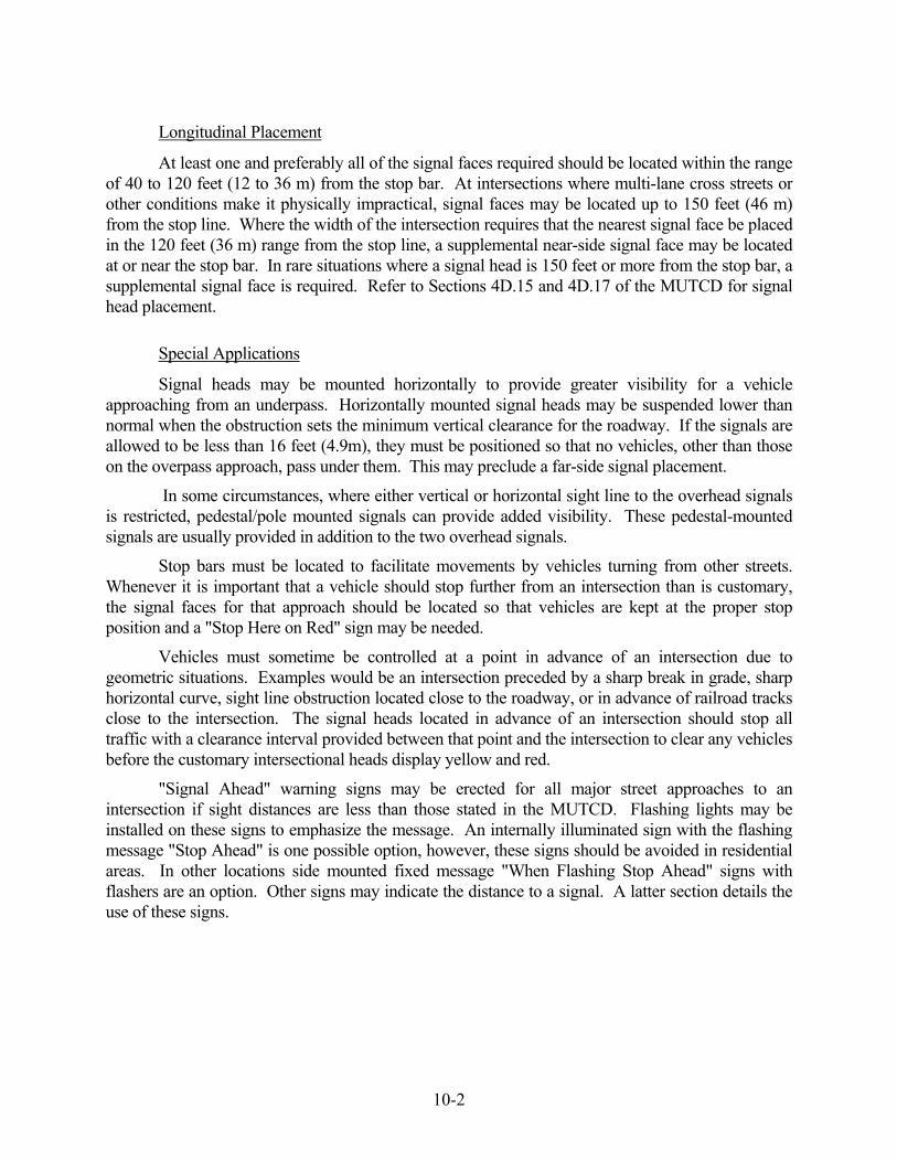
10-2
Longitudinal Placement
At least one and preferably all of the signal faces required should be located within the range of 40 to 120 feet (12 to 36 m) from the stop bar. At intersections where multi-lane cross streets or other conditions make it physically impractical, signal faces may be located up to 150 feet (46 m) from the stop line. Where the width of the intersection requires that the nearest signal face be placed in the 120 feet (36 m) range from the stop line, a supplemental near-side signal face may be located at or near the stop bar. In rare situations where a signal head is 150 feet or more from the stop bar, a supplemental signal face is required. Refer to Sections 4D.15 and 4D.17 of the MUTCD for signal head placement.
Special Applications
Signal heads may be mounted horizontally to provide greater visibility for a vehicle approaching from an underpass. Horizontally mounted signal heads may be suspended lower than normal when the obstruction sets the minimum vertical clearance for the roadway. If the signals are allowed to be less than 16 feet (4.9m), they must be positioned so that no vehicles, other than those on the overpass approach, pass under them. This may preclude a far-side signal placement.
In some circumstances, where either vertical or horizontal sight line to the overhead signals is restricted, pedestal/pole mounted signals can provide added visibility. These pedestal-mounted signals are usually provided in addition to the two overhead signals.
Stop bars must be located to facilitate movements by vehicles turning from other streets. Whenever it is important that a vehicle should stop further from an intersection than is customary, the signal faces for that approach should be located so that vehicles are kept at the proper stop position and a "Stop Here on Red" sign may be needed.
Vehicles must sometime be controlled at a point in advance of an intersection due to geometric situations. Examples would be an intersection preceded by a sharp break in grade, sharp horizontal curve, sight line obstruction located close to the roadway, or in advance of railroad tracks close to the intersection. The signal heads located in advance of an intersection should stop all traffic with a clearance interval provided between that point and the intersection to clear any vehicles before the customary intersectional heads display yellow and red.
"Signal Ahead" warning signs may be erected for all major street approaches to an intersection if sight distances are less than those stated in the MUTCD. Flashing lights may be installed on these signs to emphasize the message. An internally illuminated sign with the flashing message "Stop Ahead" is one possible option, however, these signs should be avoided in residential areas. In other locations side mounted fixed message "When Flashing Stop Ahead" signs with flashers are an option. Other signs may indicate the distance to a signal. A latter section details the use of these signs.

10-3
Visual Shielding Devices
In cases where intersection alignment results in a comparatively small angle between the orientation of signal lenses on intersecting approaches, each signal lens should be shielded. Tunnel visors and/or louvers can usually provide the screening. If louvers are required, the characteristics of both straight vane louvers and cut-off louvers should be considered. The guidelines on Figure 10-1 may be used to determine screening types.
Visors
The standard visor that is attached to each signal section is the partial visor or cap visor. It is intended to shade the lens from sunlight and prevent "sun phantom". It is open on the bottom which allows visibility to a driver passing beneath or a pedestrian on the side of the road. Unless otherwise specified the signal will have cap visors. Tunnel visors, which are full circle visors with a cutout section at the bottom, may be used to screen the signal from an adjacent approach. The tunnel visor should not be confused with the full circle visor which is not used by the Department because it holds snow and is a convenient bird nest site.
Louvers
Louvers may be inserted in a tunnel visor to provide a narrow cone of visibility. The most common type used by the Department is the 5 vane cut-off type. The vanes are angled 7 degrees and limit the visibility more on one side than the other. Louvers reduce the light intensity however, since the advent of LED signals, which are much brighter than incandescent, this is less of a concern. The designer must indicate which direction is cut-off, left or right. For example: if the vehicles to the right of the approach should not see the indication, the louvers are described on the plan as cut-off right. It should be noted that louvers are not used on arrow indications.
Visibility Limiting Signals
Visibility limiting signals, which are optically programmed signals, are also an acceptable method of screening. These signals restrict signal visibility to the traffic in a specific lane and/or at a specified distance from the signal. Unlike conventional louvers and visors, optically programmed signals do not reduce the light intensity of the display. Optically directed signals provide an optical cut-off of the indication, both vertically and horizontally as needed. Satisfactory operation of visibility limiting signals depends on correct alignment. Therefore, the signal face should be mounted on a rigid support rather than a span wire. With the use of an optically programmed signal, a sight triangle must be shown on the signal design plan to indicate the cone of visibility to the indication.
Backplates
Backplates may be attached to the signal housing to improve the contrast against the background. A backplate is a flat black rectangular frame surrounding the signal face. It extends 5 inches (125 mm) beyond all sides. A west-southwest approach during the evening or an east-southeast approach during the morning may require backplates to help lessen sun effect.
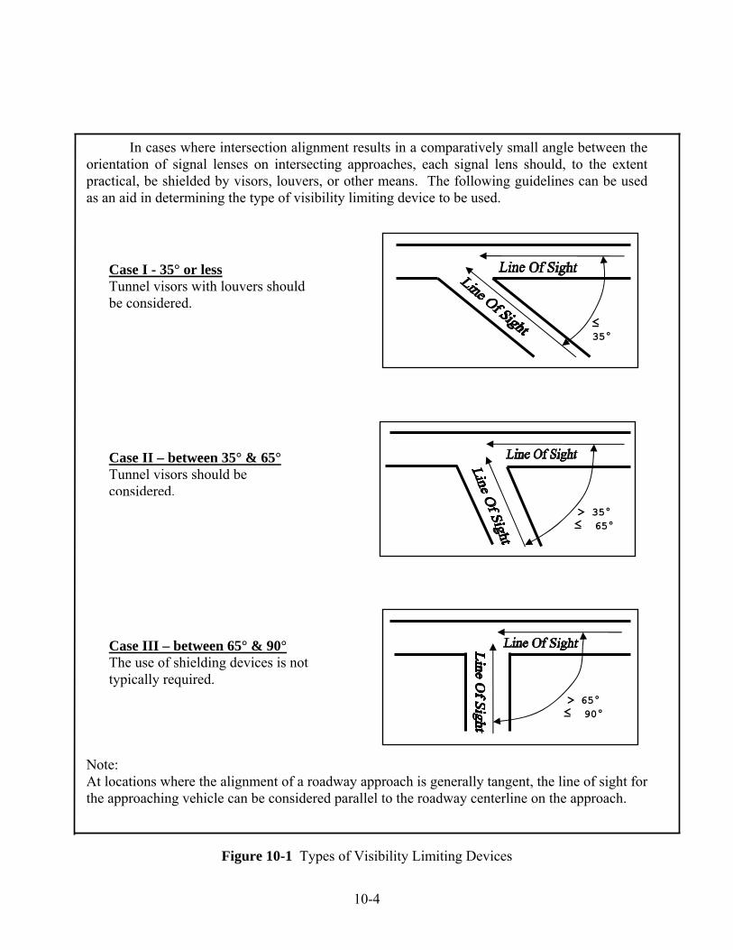
10-4
In cases where intersection alignment results in a comparatively small angle between the orientation of signal lenses on intersecting approaches, each signal lens should, to the extent practical, be shielded by visors, louvers, or other means. The following guidelines can be used as an aid in determining the type of visibility limiting device to be used.
Note: At locations where the alignment of a roadway approach is generally tangent, the line of sight for the approaching vehicle can be considered parallel to the roadway centerline on the approach.
Figure 10-1 Types of Visibility Limiting Devices
Case III – between 65° & 90° The use of shielding devices is not typically required.
> 65° ≤ 90°
Case I - 35° or less Tunnel visors with louvers should be considered.
≤ 35°
Case II – between 35° & 65° Tunnel visors should be considered.
> 35° ≤ 65°

10-5
Signal Lens Size and Type
All signal lenses, except for exclusive pedestrian indications, are circular. For information on size of exclusive pedestrian indications see Chapter 11. There are two sizes for circular lenses, 8 inch (200 mm) and 12 inch (300 mm).
1. 12 inch (300 mm) lenses will normally be used.
2. 8 inch (200 mm) lenses may be used under the following conditions:
a. When pedestrian indications are provided for crossing on side street green, every effort should be made to pedestal or pole mount these indications for better visibility by the pedestrian.
b. Based on engineering judgment due to the geometric configuration, such as for minor private driveways or in residential or historical areas for aesthetic reasons.
c. When signals are installed at two closely spaced intersections, it is desirable to provide simultaneous yellow indications followed by simultaneous red indications. If that cannot be reasonably accomplished, the signal heads which are nearest the approaching driver should be clearly distinguishable from those that are farthest away. Providing 12 inch (300 mm) lenses on the nearest set of indications and 8 inch (200 mm) lenses on those farthest away may provide this contrast.
Signal indications and pedestrian indications are usually illuminated by light emitting diode (LED) lamps. Conventional incandescent lamps consume up to 150 watts of power and require routine maintenance due to filament burn out. LED lamps are now in use to conserve energy and reduce maintenance costs. An LED is a current operated, semiconductor light source. LED power requirements are considerably less than incandescent lamps.
Signal Support Structures
Type
Generally, at least two support structures are needed in order to locate the signal heads as previously described. The most common types are a span pole or a mast arm assembly. Utility poles can be used in combination with steel poles to support signal heads. The use of utility poles is discussed later. A steel span pole is a pole to which span wire is attached for the purpose of supporting the signal heads. A steel mast arm assembly is a cantilever structure that permits the overhead installation of the signal heads without overhead span wire and signal cables. Combination structures (either span pole or mast arm assembly) are used to support a luminaire as well as the signal heads. Signal support structures in the following sections will be referred to as either "support" or "pole".

10-6
The support must be strong enough to sustain the weight of the signals and cables and tall enough to provide a minimum signal housing clearance of 16 feet (4.8 m) from the road surface. The support is made of steel, in accordance with current AASHTO Standard Specifications. The support is bolted to a 10 foot (3 m) deep, 3 foot (1 m) diameter, reinforced cast-in-place concrete foundation. A typical support structure is designed to hold in excess of 7000 lbs. (31,000 N) of torque and therefore cannot be designed as breakaway.
For temporary installations, a wood pole other than a utility pole can be used to support a span wire. Because the Department does not have a wood pole maintenance program, this type of support cannot be used for a permanent installation. If a wood pole is used, there must be sufficient right-of-way for an anchor and guy opposite the span.
Placement
The major factors to consider when determining a pole location are optimal signal head placement, safety for vehicles and pedestrians, clearance to utilities (overhead and underground) and aesthetics. After installation, the pole may be in place for 20 years or more before a re-design and therefore, the designer should carefully consider all factors.
The current far-side signal design practice suggests a pole on each corner of the intersection. This enables excellent lateral and longitudinal signal and sign placement as well as providing a structure for pedestrian pushbuttons and walk signals.
A pole is considered a fixed object and should be located to minimize the possibility of being struck by a vehicle that has left the road. Poles should be set if possible, behind any existing protective device already at the intersection such as beam rail or wire rope rail and beyond the deflection limit of the device. Where right-of-way will allow, the poles should be set outside the clear zone. Refer to the Department’s Highway Design Manual (reference 2) for recommended clear zone distances. When placed on side slopes, signal supports are usually located closer to the roadway on downward sloping embankments than on upward sloping ground. Signal supports at the side of a street with curbs shall have a horizontal clearance of not less than 2 feet (0.6 m) from the vertical face of the curb. Where there is no curb, supports shall have a horizontal clearance of not less than 2 feet (0.6 m) from the edge of the road. Poles should not be located opposite the stem of a tee type intersection for several reasons. This poses a fixed object hazard especially directly opposite an expressway exit ramp. Also, poles should not be located in areas which are likely to contain a drive if the property opposite the stem of the tee is developed. Poles including pedestals should not obstruct a crosswalk or sidewalk. A free path not less than 3 feet (1 m) must be available for pedestrians in accordance with the requirements of the Americans with Disabilities Act. In addition to not creating a fixed object for motorists and pedestrians, the designer should not create a sight line obstruction. Although a support structure is only approximately 16 inches in diameter, when placed in line with other objects such as pedestals, controller cabinets and utility poles, it may obstruct intersection sight distances.

10-7
There are usually utilities, both overhead and underground, that the designer must consider when locating a support structure. There are certain clearances that must be met for safety reasons. The utility issues are discussed in depth in the Electrical section of this manual. Briefly, all signal appurtenances should be located 10 feet (3 m) from a utility pole. All support structures should be 10 feet (3 m) from primary power lines which are usually carried on 8 foot or 10 foot (2.4 m - 3.0 m) cross arms at the top of the utility pole. Support foundations must be a minimum 5 feet (1.5 m) from underground utilities.
In keeping with context-sensitive-design practice, the designer should consider the area where a proposed pole will be installed. Some of the more common areas to be avoided are the following locations; in front of a business/municipal sign; in front of a business or residence entrance; in the front yard of a residence; in front of a historical building or in a landscaped area. Other large signal appurtenances, such as controller cabinets, should be kept out of these same areas.
Finish
All steel support structures are hot dipped galvanized to prevent corrosion. When new, the finish has a silvery shine. Over time, the finish oxidizes to a light gray. When a support is placed in an architectural streetscape setting, the pole may be painted after galvanizing to match other structures. Ornamental hardware such as base covers and pole caps are available and have been used by several municipalities in downtown areas. If a municipality desires a colored pole or ornamental hardware at an existing State owned intersection, the State will not participate in funding the cost of those appurtenances. If colored poles or ornamental hardware is being installed at locations in projects, such as new installations, the cost is funded in the project. In either case, the municipality must also enter into an agreement with the State to assume the maintenance responsibility for the paint and any ornamental hardware. It should be noted that a painted or ornamental structure that has been damaged will be replaced by the Department with standard, in-stock equipment and not with one of the same type.
Use of Utility Poles
There are often utility poles on the corners of an intersection. It is an acceptable practice to attach a span wire to a utility pole rather than installing another pole. When attaching to utility poles there are certain DPUC (Department of Public Utility Control) regulations and NESC (National Electric Safety Code) clearances that must be followed. There is additional information on this in the Utility Considerations section of this manual. Briefly, the span attachment point must be a minimum of 12 inches (300 mm) below the secondary lines and 40 inches (1000 mm) above the highest communications lines. If the clearances are not present, the utility pole may be replaced with a taller one. The utility pole must be anchored and guyed opposite the span and therefore, sufficient right-of-way must be available. Any attachment to a utility pole must be discussed with and agreed to by the utility companies. The location of utility poles is generally determined by the custodian. The designer may request a more desirable location for a utility pole however, this could be costly if that also requires the re-design and replacement of the nearby power distribution system and communication circuits.
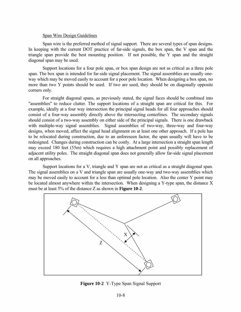
10-8
Span Wire Design Guidelines
Span wire is the preferred method of signal support. There are several types of span designs. In keeping with the current DOT practice of far-side signals, the box span, the V span and the triangle span provide the best mounting position. If not possible, the Y span and the straight diagonal span may be used.
Support locations for a four pole span, or box span design are not as critical as a three pole span. The box span is intended for far-side signal placement. The signal assemblies are usually one-way which may be moved easily to account for a poor pole location. When designing a box span, no more than two Y points should be used. If two are used, they should be on diagonally opposite corners only.
For straight diagonal spans, as previously stated, the signal faces should be combined into "assemblies" to reduce clutter. The support locations of a straight span are critical for this. For example, ideally at a four way intersection the principal signal heads for all four approaches should consist of a four-way assembly directly above the intersecting centerlines. The secondary signals should consist of a two-way assembly on either side of the principal signals. There is one drawback with multiple-way signal assemblies. Signal assemblies of two-way, three-way and four-way designs, when moved, affect the signal head alignment on at least one other approach. If a pole has to be relocated during construction, due to an unforeseen factor, the span usually will have to be redesigned. Changes during construction can be costly. At a large intersection a straight span length may exceed 180 feet (55m) which requires a high attachment point and possibly replacement of adjacent utility poles. The straight diagonal span does not generally allow far-side signal placement on all approaches.
Support locations for a V, triangle and Y span are not as critical as a straight diagonal span. The signal assemblies on a V and triangle span are usually one-way and two-way assemblies which may be moved easily to account for a less than optimal pole location. Also the center Y point may be located almost anywhere within the intersection. When designing a Y-type span, the distance X must be at least 5% of the distance Z as shown in Figure 10-2.
Figure 10-2 Y-Type Span Signal Support
X
Z
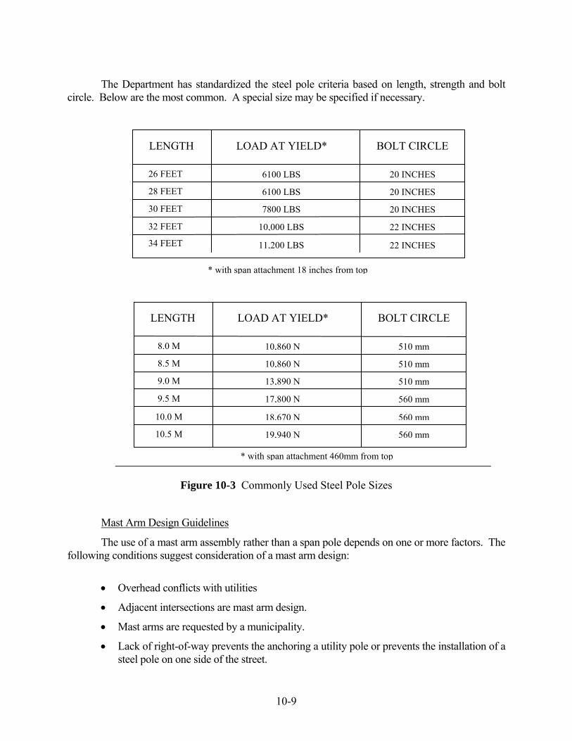
10-9
The Department has standardized the steel pole criteria based on length, strength and bolt circle. Below are the most common. A special size may be specified if necessary.
Figure 10-3 Commonly Used Steel Pole Sizes
Mast Arm Design Guidelines
The use of a mast arm assembly rather than a span pole depends on one or more factors. The following conditions suggest consideration of a mast arm design:
• Overhead conflicts with utilities
• Adjacent intersections are mast arm design.
• Mast arms are requested by a municipality.
• Lack of right-of-way prevents the anchoring a utility pole or prevents the installation of a steel pole on one side of the street.
* with span attachment 460mm from top
10.5 M
18,670 N
13,890 N
17,800 N
10,860 N
10,860 N
560 mm
510 mm
560 mm
510 mm
510 mm
10.0 M
9.0 M
9.5 M
8.5 M
8.0 M
LENGTH LOAD AT YIELD* BOLT CIRCLE
560 mm19,940 N
11,200 LBS
7800 LBS
10,000 LBS
6100 LBS
6100 LBS
22 INCHES
20 INCHES
22 INCHES
20 INCHES
20 INCHES
34 FEET
30 FEET
32 FEET
28 FEET
26 FEET
LENGTH LOAD AT YIELD* BOLT CIRCLE
* with span attachment 18 inches from top

10-10
It is required that the designer confer with municipal officials prior to designing an intersection to determine which type of support is desired. Local opinions regarding the aesthetics of a mast arm design vary widely from municipality to municipality. If a mast arm is chosen for the support structure, a design using fixed-mounted signals is preferred. Under certain circumstances a free-swinging design may be necessary.
A mast arm design eliminates most potential overhead conflicts with utilities. Unless it is a combination structure, the height is low enough not to conflict with primary wires. Because the arm is usually 18 to 20 feet (5.5 to 6.0 m) over the road, the designer should be most concerned with communication cables which are at the same elevation.
Each mast arm structure is assigned an identification number. It consists of the state intersection number with a letter suffix. It is used to identify the structure for inspection and maintenance purposes. Mast arm information which lists the ID number, shaft height, and arm length is placed on the signal plan as shown in Figure 16-7.
As well as selecting the arm length, the designer must establish the shaft height and the arm attachment point. The arm attachment point depends on the difference in elevation between the proposed foundation and the high point of the road under the proposed arm. The shaft height is generally 1.5 to 2 feet (0.45 to 0.6 m) higher than the attachment point. Round up to the nearest foot if the design is in English units or 0.5 m if in metric.
A profile and a plan view of each mast arm assembly must be developed. The profile will illustrate the structure, foundation, and the signals in relation to the road. The view shall be perpendicular to the arm. The profile should also show any other traffic appurtenances (signs, luminaries, cameras, etc.) supported by the mast arm assembly as well as the dimensions from the centerline of the base of the shaft to each traffic appurtenance mounted to the shaft. The mast arm structure identification number should be shown on the profile. An example profile is shown in Figure 10-4.
The plan view is an overhead illustration of the mast arm assembly showing all traffic appurtenances attached to the arm and the distance from each to the centerline of the shaft. The plan view should also include the area and weight of any signs attached to the mast arm assembly. Sheet aluminum sign weight, including mounting hardware, is based on 4 lbs./sq. ft. (19.53 kg/m2). An example plan view is shown in Figure 10-5.
If there is enough space on the signal plan under the construction notes, the profile and plan view may be shown there. If not, the profile and plan view should be shown on a separate plan sheet.
AASHTO Standard specifications for Structural Supports for Hwy Signs, Luminaries and Traffic Signals – 2001 with the latest interim specifications govern the structural design of all mast arm assemblies in Connecticut, State owned and Town owned. In addition to the AASHTO specs, the Department has developed criteria for the fabrication of all mast arm assemblies and foundations that will be owned by the State. Specifications and detail sheets are available to a consultant upon request.
Mast arm assemblies owned by a municipality are not required to meet the Departments criteria. The town may use an alternate design providing it conforms to the 2001 AASHTO requirements with the latest interim specifications and the foundation meets the Departments design standard.

10-11
Figure 10-4 Mast Arm Assembly Profile View
Example: Determine the attachment point and shaft height of a 40 foot mast arm. The height (clearance) to bottom of signal housing at high point of road is 17 feet. Note: A signal clearance of at least 16 feet (4.8 m) over the road should be provided.
• Fixed mounted signal design requires the arm to be positioned behind the center of the
signal assembly. Therefore the arm height should be 17 feet + half the height of the largest signal, which in the example equals 19 feet. It should be noted that free swinging signal design requires the arm to be 1 foot above the signal assembly.
• Establish the vertical rise of the arm = Sine 3° x arm length = 0.052 x 40 feet = 2 feet.
• Calculate the attachment point of the arm = Arm height – vertical rise ± foundation height in relation to the road = 19 feet – 2 feet – 1.7 feet = 15.3 feet.
• The shaft height should be 1.5 feet higher than the calculated attachment point = 15.3 feet + 1.5 feet ≈ 17 feet

10-12
Figure 10-5 Mast Arm Assembly Plan View

11-1
11 PEDESTRIAN/BICYCLIST CONSIDERATIONS
The design and operation of a traffic control signal takes into consideration the particular characteristics of the intersection as well as the needs of vehicular, pedestrian and bicycle traffic. When pedestrians or bicyclists approach a signalized intersection they are legally required to follow the same red, yellow, and green indications that are provided to control the motorist unless there are separate pedestrian indications.
There are circumstances where it is reasonable to expect pedestrians to have a need to cross a street. If the basic signal operation does not include satisfactory provision for pedestrians, they may need access to a push button that would modify the basic signal operation to provide suitable phasing and timing. Chapter 4E of the MUTCD can be consulted for guidance on pedestrian control features and placement of equipment.
Due to the wide variety of field conditions, it is not possible to list all situations where push buttons should or should not be provided; however, the majority of situations may be accounted for by considering the pedestrian presence potential and need. Each pedestrian/bicyclist crossing movement should be considered on a case-by-case basis however, in general, most intersections require some type of pedestrian provisions.
There are a limited number of situations where pedestrian push buttons do not need to be provided. These include:
1. Remote areas without indications of a pedestrian/bicyclist presence.
2. The pedestrian crossing would be to an area restricted to pedestrians, e.g., expressway ramps.
3. The pedestrian crossing would otherwise be illegal.
4. One of the termini at the crossing lacks a walking area or a reasonable site for a pedestrian presence and is considered potentially hazardous, e.g., physically restricted by guide rail, steep embankment, retaining walls, bridge pier or abutments.
In those instances where pedestrian push buttons are not provided, the Local Traffic
Authority should be consulted. The exclusion of pedestrian push buttons itself does not require an action by the State Traffic Commission. However, if no pedestrian push buttons are included in the signal design then "No Pedestrian Crossing" signs should be installed. These signs are a regulatory item, and therefore a State Traffic Commission report approving their installation is required.
Pedestrian buttons should be located in an accessible area reasonably removed from traffic. In areas of continuous sidewalks, the pedestrian buttons should be accessible from the sidewalk in accordance with the Americans with Disabilities Act (ADA). If attached to a support structure or controller cabinet that is not adjacent to the sidewalk, a section of sidewalk should be extended to the button. If the sidewalk does not have a ramp, the construction of a pedestrian ramp and landing area should be pursued. All pedestrian buttons installed shall be ADA compatible in regard to mounting height, operating force and size.

11-2
The choice of locations for pedestrian buttons may be influenced by signal phasing and/or turning volumes. For example, at an intersection with a double left-turn lane on the sidestreet (without an exclusive pedestrian phase), it is generally preferable to cross pedestrians on the artery leg that is not receiving the double left-turn movement.
On roadway reconstruction projects the designer should check the placement of guide rail that may not be shown on the signal plan and may restrict access to push buttons. The designer should also check the cross section plans for embankments and slopes.
Pedestrian Actuated Side Street Green
Pedestrian actuation of side-street green for crossing the arterial may require more time than might otherwise be allotted to the side street phase. Pedestrians should normally be provided time to cross from curb line to curb line at a normal walking speed of 3.5 feet per second (1.1 m/sec). In areas where elderly pedestrians, pedestrians with disablities, or pedestrians who may travel at a slower pace are expected, a walking speed of less than 3.5 feet per second (1.1 m/sec) should be considered. The calculated pedestrian crossing time is shown on the signal plan in the WALK and PED CLR rows under the appropriate vehicle phase. Typically one second is entered as the PED CLR time and the remainder of the required time is entered as the WALK time. Limiting the PED CLR time to one second allows for a more efficient manual operation of the signal as this time cannot be skipped.
The designer should ensure that a side street signal indication is visible to the pedestrian. This will likely require an auxiliary signal head in the case of a "tee" intersection. In addition, at intersections with split side street phasing, signal faces for pedestrians may need to be shielded.
Pedestrian Actuated Walk/Don’t Walk
Pedestrian signal heads are special types of traffic signal indications intended for the exclusive purpose of controlling pedestrian traffic. They may also be of use to bicyclists. These heads consist of the illuminated symbols of a walking person (symbolizing walk) and an upraised hand (symbolizing don't walk). The meanings of pedestrian signal heads are as follows:
1. The upraised hand symbol, steadily illuminated, means that a pedestrian shall not enter the roadway in the direction of the head.
2. The upraised hand symbol, while flashing, means that a pedestrian shall not start to cross the roadway in the direction of the head, but that any pedestrian who has partly completed the crossing during the steady walk symbol shall proceed to the other side of the road, or to a safety island.
3 The walking person symbol means that a pedestrian facing the signal head may proceed across the roadway in the direction of the head. The walking person symbol means that there may or may not be possible conflict of pedestrians with turning vehicles.

11-3
Pedestrian signal heads may be used in conjunction with a pedestrian phase where all vehicle traffic (except right-turn-on-red) is stopped. This is commonly referred to as an "exclusive" pedestrian phase. Pedestrian calls are remembered by the controller regardless of the phase mode setting. To minimize the potential for unnecessary vehicle calls during the initialization of the controller, the exclusive pedestrian phase mode should be set to non-lock.
Pedestrian signal heads may also be used to control when pedestrians may start to walk with the green indication for vehicles going parallel to the pedestrian crossing. When the artery is on recall, pushbuttons are needed only to actuate the side street phase. The artery phase is placed on pedestrian recall, as well as vehicle recall, and buttons are not needed to cross the side street. A special pedestrian pushbutton sign is needed such as 31-0838 (with arrow).
In normal practice the walk indication is displayed for a period of time, typically seven (7) seconds, to allow a group of people behind the curb to realize they may start to walk and step into the street, but be watchful of turning cars. The flashing don't walk clearance should provide sufficient time for the pedestrian to walk from the curb line to the far side of the traveled way or to a median of sufficient width for pedestrians to wait at a normal walking speed of 3.5 feet per second (1.1 m/sec). In areas where elderly pedestrians or pedestrians who may travel at a slower pace are expected, a walking speed of less than 3.5 feet per second (1.1 m/sec) should be considered.
Pedestrian signal heads should be conspicuous and recognizable to pedestrians at all distances from the beginning of the controlled crossing to a point 10 feet (3 m) from the end of the controlled crossing during both day and night.
LED pedestrian signal heads are available in both 8 inch (200 mm) high or 11 inch (280 mm) high symbols. The 11 inch (280 mm) high symbols are appropriate at locations where the pedestrian enters the crossing more than 100 feet (30 m) from the pedestrian signal head. The 8 inch (200mm) high symbols are used at locations where the crossing distance is shorter or where there are aesthetic considerations. The size of the pedestrian signal head should be noted on the signal plan.
A number of different configurations are currently available for pedestrian signal heads. The configuration required for use at State owned traffic signals is the walking person symbol and the upraised hand symbol located side by side (with two separate symbols). At town owned traffic signals, the use of symbols overlaid on each other is also acceptable.
Accessible Pedestrian Signals (APS)
Audible pedestrian signals can be installed when there is a request made on behalf of a visually impaired pedestrian and the Division of Traffic Engineering verifies the need with Connecticut Services for the Blind and the Local Traffic Authority (LTA). The audible signal shall be active to coincide with the visual walk indication and pulse to coincide with the visual don’t walk indication. As noted in the MUTCD, under stop and go operation, audible pedestrian signals shall not be limited in operation by time of day or day of week. The words "Audible Ped Signal" should be placed on the signal plan as shown in the Signal Plan Layout section of this manual. Audible pedestrian signals should only be used in exclusive pedestrian signal phasing.
When an existing traffic control signal that has an audible signal is redesigned, the need to maintain the audible signal equipment should be confirmed with the Connecticut Services for the Blind and the LTA by the Division of Traffic Engineering.
11-4
Countdown Pedestrian Signals
The MUTCD allows the optional use of countdown pedestrian signals (a pedestrian interval countdown display added to a pedestrian signal head) in order to inform pedestrians of the number of seconds remaining in the pedestrian change interval. The countdown timer merely repeats the previous cycle pedestrian clearance time and operates independent of the controller setting. To prevent an incorrect countdown time, shortening the pedestrian clearance interval is not allowed for any reason including emergency pre-emption and manual operation.
Countdown pedestrian signals are only allowed on municipally owned signals. In addition, they cannot be used at a signal with railroad pre-emption or at a signal where multiple pedestrian movements are overlapped. In these cases the pedestrian clearance times may vary, giving inconsistent countdown times.
When it has been determined that a countdown pedestrian signal is desired, the following requirements apply:
• To be consistent with MUTCD requirements, the following technical note should be placed on the signal plan, “Countdown displays shall not be used during the walk interval nor during the yellow change interval of a concurrent vehicular phase.”
• When used with an exclusive pedestrian phase, the pedestrian clearance interval should be set approximately 4 seconds less than the normally required pedestrian crossing time. The yellow clearance interval for the phase should be set to 4 seconds to provide a clearance between the end of the countdown and the start of the conflicting green.
• As previously stated, a consistent pedestrian clearance is essential for the accuracy of the countdown timer. When the intersection is under manual control, most interval times (including the pedestrian clearance) are determined by the manual operator. The operator cannot ensure the same ped clearance time each time the controller is advanced out of the pedestrian phase. To ensure a consistent display on the pedestrian signal, the following technical note should be placed on the signal plan. "Manual and interval advance to be disconnected during phase (insert pedestrian phase #) pedestrian clearance interval".
• The note "Countdown Ped Signal" should be placed on the signal plan as shown in the Signal Plan Layout section of this manual.

12-1
12 SIGNING AND PAVEMENT MARKINGS
The extent of lane use signing and pavement marking should be kept to a minimum while being consistent with State Traffic Commission Regulations, the Manual on Uniform Traffic Control Devices (latest edition) and that required for safe and efficient operation at the specific location. Unusual geometric conditions, signal phasing, specific signing needs and operations peculiar to a specific location may suggest other treatments.
In general, movements that are obvious, consistent with basic motor vehicle law, and consistent with driver expectancy do not require redundant expression.
It is desirable to place signs so that they have the greatest target value for the driver. In areas with sheltered turn lanes, the "turn only" sign should be placed overhead. It is also preferable to place "No Turn On Red" signs overhead. Signs which are generally no larger than 24 in. x 24 in. (0.6 m x 0.6 m) can be span-mounted. Exceptions to this are “LEFT TURN SIGNAL” and “RIGHT TURN SIGNAL” signs which can be 24” x 30” (0.6 m x 0.75 m).
When post-mounted lane-use control signs are used, one should be placed in the vicinity of the stop bar and another should be placed sufficiently in advance of the intersection so that the driver may select the appropriate lane. Supplemental, post-mounted, lane-use signs may be used with overhead lane-use signs.
Pavement marking arrows may be used to supplement the lane-use control signing. They are generally used for specific turn lanes. When used, the first arrow, closest to the intersection, should be placed 40 feet (12 m) from the stop bar. The specific turn arrow marking will suffice. The word "Only" is not used.
For additional information on pavement marking details, refer to the Office of Engineering’s Drawing "Special Details & Typical Pavement Markings for Two-way Highways" which is available on the DOT’s website.
There are various reflective intensities for signs used at signalized intersections. For specific information regarding legend, size and material type, refer to the DOT’s Catalog of Signs - latest edition, which is available from the Division of Traffic Engineering.
See Chapter 21, Preliminary Design Requirements, Item # 10 for details on plan preparation when a signing and pavement marking plan is needed in addition to the signal plan.

13-1
13 MERRITT PARKWAY GUIDELINES
Span poles will be selected to be as unobtrusive as possible. Existing utility poles will be used for supports where feasible. Galvanized steel poles will be the standard pole when utility poles are not available. Depending on the setting, the poles shall be painted either charcoal gray or dark green when the normal galvanized finish is not aesthetically appropriate for the area. Typically, charcoal gray is used.
Signing and pavement marking will follow normal state practice.

14-1
14 FLASHING MESSAGE SIGNS
There are locations where motorists traveling on the main (artery) roadway may encounter conditions that restrict the visibility to the signal faces, queued vehicles or both. Field measurements can determine whether these visibility inadequacies exist. If the sight restriction to either the signal heads or a queue of vehicles or both is caused by the vertical alignment of the road, a roadway profile may be necessary to assist the designer.
Many countermeasures can be implemented to address these visibility concerns such as the installation of auxiliary signal heads, regrading, vegetative clearing, signal retiming, etc. However, it may be determined that a flashing sign, integrated with the signal operation, is needed. This chapter provides guidance on the design of such a sign if such a countermeasure is determined to be appropriate.
A flashing sign, integrated with the signal operation, may also be appropriate for the following situations.
• Expressway terminus signals.
• Remote signalized locations where motorists would not expect to come upon a traffic control signal.
When these signs are provided at expressway terminus signals or remote signalized locations, the use of the methodology for "Inadequate Visibility to Signal Heads" which follows is suggested.
A static “Signal Ahead” sign should also be provided in advance of all flashing sign installations. In general, the signal indications and flashing sign should not be visible to motorists at the same time.

14-2
Inadequate Visibility to a Queue of Stopped Vehicles
Under this situation, a side mounted “Be Prepared to Stop” sign with flashers, and a “When Flashing” subplate is typically used.
Determining the Critical Queue
The critical queue is the longest queue that could accumulate that does not have adequate stopping sight distance for approaching vehicles. It should be noted that the maximum queue is not necessarily the critical queue. It may be difficult initially to establish this value. The potential for this condition to occur is first determined by a field visit to the intersection. A more precise queue length estimation is later calculated through a capacity/queue analysis. It is essential that turning movement counts are obtained for periods when peak queue build ups are likely so the effect of heavy left or right turning movements with or without turn lanes can be properly evaluated. The effect of future traffic growth should also be considered.
Locating the sign
Calculate the stopping sight distance to the critical queue to permit approaching vehicles traveling at the 85 th percentile speed to stop prior to reaching the queue. When locating the sign, include a distance reduction of 175 feet for sign visibility. This results in the sign being placed, at a minimum, a distance of (SSD – 175 feet) from the critical queue. Further adjustments to the sign location may be necessary to ensure proper sign visibility.
Stopping Sight Distance (SSD) = a
VVt2
075.147.1 + (Level alignment)
Stopping Sight Distance (SSD) = )
2.32(30
47.12
GaVVt
±+ (On grade)
where: t = brake reaction time, 2.5 seconds
V = 85 percentile speed, mph
a = deceleration rate, 11.2 ft/sec2
G = the percent of grade divided by 100
Refer to Figure 14-1 for an example of locating the sign.

14-3
Determining time when Flashing Operation Occurs
Per the 2003 MUTCD Section 4D-15, page 4D-16, the sign should be timed in such a manner as to flash during the period when road users passing the sign at the speed limit for the roadway might encounter a queue resulting from the display of a red signal upon arrival at the signalized location. The sign should begin flashing at the onset of the artery yellow and remain on while the artery is red and through the portion of artery green time (Gc) needed to process the critical queue which accumulated on the approach. This green time (Gc) can be calculated using the following formula:
Gc = 3.7 + 2.1 (N)
where N is the number of queued vehicles.
For this application a “dummy” phase which precedes the artery phase is necessary to accommodate the sign operation. The portion of artery green time (Gc) needed to process the queue which accumulated on the approach is entered in the “dummy” phase as shown in the movement diagram in Figure 14-2. Since the “dummy” phase precedes the artery phase, appropriate yellow and red clearance intervals are placed in the artery phase.
The use of a "dummy" phase is the preferred method to accommodate the sign operation however, there are certain phasing conditions that may prevent the use of a dummy phase to obtain "Gc".
• Advance phase preceding the artery phase in the opposite direction of the sign. • Dual ring sequence The necessary time "Gc" may then be taken from the walk interval of the associated artery
phase. Under these conditions, the design should be reviewed by the Signal Lab to ensure the timing and sequence is correct and all pertinent technical notes are included.
Signals with certain pre-emption sequences may cause the sign operation to time incorrectly. Therefore, any locations with pre-emption where a flashing sign is proposed or where a revision is proposed at a signal having flashing signs, the designer should have the design reviewed by the Signal Lab prior to approval. Pre-emption sequences which could cause the sign operation to time incorrectly will not be allowed.
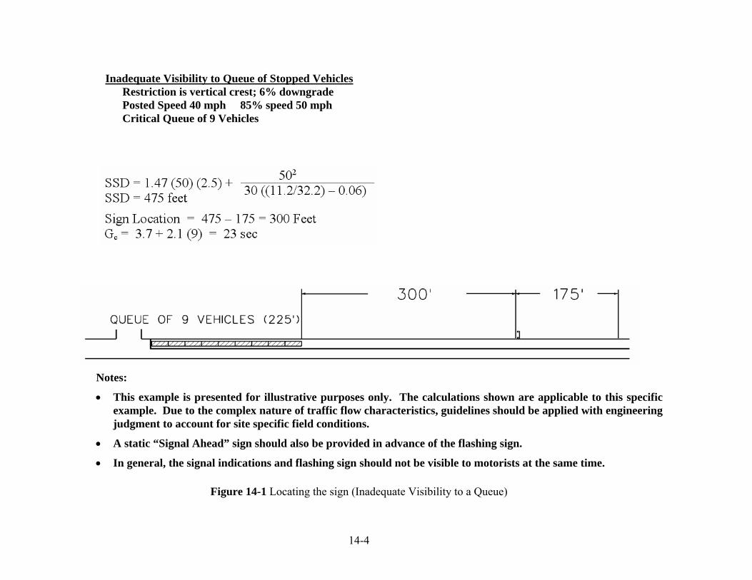
14-4
Figure 14-1 Locating the sign (Inadequate Visibility to a Queue)
Inadequate Visibility to Queue of Stopped Vehicles Restriction is vertical crest; 6% downgrade Posted Speed 40 mph 85% speed 50 mph Critical Queue of 9 Vehicles
Notes:
• This example is presented for illustrative purposes only. The calculations shown are applicable to this specific example. Due to the complex nature of traffic flow characteristics, guidelines should be applied with engineering judgment to account for site specific field conditions.
• A static “Signal Ahead” sign should also be provided in advance of the flashing sign.
• In general, the signal indications and flashing sign should not be visible to motorists at the same time.

14-5
Figure 14-2 Sequential Phasing with a “Dummy” Phase
Gc

14-6
Inadequate Visibility to Signal Heads
Under this situation, a side mounted “When Flashing Stop Ahead” sign with flashers or an overhead flashing “Stop Ahead” sign should be considered. A side mounted sign is generally used however there are special situations such as multiple lane approaches to expressway termini where an overhead sign may be necessary.
When motorists will have restricted visibility to both signal faces and queued vehicles (on the same approach), the “When Flashing Stop Ahead” sign with flashers or an overhead flashing “Stop Ahead” sign should be considered. The sign should be located based on the methodology that yields the greatest distance from the stop bar.
Locating the sign
Calculate the stopping sight distance (SSD) needed for a vehicle traveling at the 85 th percentile speed to stop at the stop bar. Place the sign, at a minimum, a distance of the calculated SSD from the stop bar. Further adjustments to the sign location may be necessary to ensure proper sign visibility.
Stopping Sight Distance (SSD) = a
VVt2
075.147.1 + (Level alignment)
Stopping Sight Distance (SSD) = )
2.32(30
47.12
GaVVt
±+ (On grade)
where: t = brake reaction time, 2.5 seconds
V = 85 percentile speed, mph
a = deceleration rate, 11.2 ft/sec2
G = the percent of grade divided by 100
Refer to Figure 14-3 for an example of locating the sign.
Determining time when Flashing Operation Occurs
Per the 2003 MUTCD Section 4D-15, page 4D-16, the sign should be timed in such a manner as to flash during the period when road users passing the sign at the speed limit for the roadway might encounter a red signal upon arrival at the signalized location. The time is that which is needed for a vehicle traveling at the speed limit to go from a point 50 feet in advance of the sign (for motorist recognition) to the stop bar. Refer to Figure 14-3 for example showing calculation of this time. This calculated clearance time (Tc) is the amount of time prior to the display of the artery yellow indication that the sign should begin flashing. The sign should stay flashing from this point until the artery green indications are displayed again.
• For coordinated or full-actuated signals and signals with any type of quad phasing, a “dummy” phase which follows the artery phase is necessary to accommodate the sign

14-7
operation. The calculated clearance time (Tc) is entered in the movement diagram as shown in Figure 14-4. This time is spread out over a combination of the yellow and red clearance intervals of the artery phase and the green interval of the “dummy” phase. The appropriate artery yellow and red clearance intervals are placed in the “dummy” phase as well as the artery phase to provide for consistent clearances to a pre-emption movement. Because of driver expectancy, once the sign(s) begins to flash the controller must service an opposing phase. The sign(s) should never begin to flash, and then turn off without the approach signals transferring to red.
Figure 14-4 is an example of an intersection with a flashing sign in one direction which is Ø2. The dummy phase must follow the artery if Ø1&5, Ø1&6 or Ø4 is next. It may be skipped only if Ø2&5 is next. Once in Ø3 and the sign is flashing, a temporary artificial call is placed in Ø1. This ensures at least one opposing phase is serviced. If the call in Ø4 is dropped during Ø3 due to right turn on red, Ø4 may be skipped however Ø1 will be serviced, even if there is no vehicle present. If Ø4 is serviced, the temporary artificial call in Ø1 is dropped and Ø1 may be skipped if there is no real demand. It should be noted that Ø1 should have presence detection and be in non-lock mode.
Figure 14-5 is an example of an intersection with a flashing sign in both directions. The dummy phase must always follow the artery. Once in Ø3 a temporary artificial call is placed in Ø1&5. If the side street calls are dropped due to right turn on red, the side street phases may be skipped, however Ø1&5 will be serviced, even if there are no vehicles present. If any side street is serviced, the temporary artificial call in Ø1&5 is dropped and Ø1&5 may be skipped if there is no real demand. It should be noted that Ø1&5 should have presence detection and be in non-lock mode.
• Signals, with an exclusive walk phase, regardless of the operation will require the use of a “dummy” phase to ensure proper sign operation.
• In the case of uncoordinated semi-actuated signals with simple sequential phasing and no exclusive walk phase, the designer may choose to enter the clearance time (Tc) in the “Don’t Walk” interval of the artery phase rather than use a “dummy” phase. This may allow the use of certain pre-emption sequences which could present timing problems to the sign operation if a “dummy phase” was used. If this operation is being considered, the signal lab should be consulted for appropriate technical notes, etc. The use of a "dummy" phase is the preferred method to accommodate the sign operation.
When using a “dummy” phase in an uncoordinated semi-actuated signal with simple sequential phasing and no exclusive walk phase, include technical notes to ensure the dummy phase always follows the artery phase. The appropriate artery yellow and red clearance intervals are placed in the “dummy” phase as well as the artery phase to provide for consistent clearances to a pre-emption movement. See movement diagram in Figure 14-6 for example of sequential phasing with a “dummy” phase.
Signals with certain pre-emption sequences may cause the sign operation to time incorrectly. Therefore, any locations with pre-emption where a flashing sign is proposed or where a revision is proposed at a signal having flashing signs, the designer should have the design reviewed by the Signal Lab prior to approval. Pre-emption sequences which could cause the sign operation to time incorrectly will not be allowed.

14-8
The use of dilemma zone detection (as described in Chapter 7) is not effective in designs where “When Flashing Stop Ahead” signs with flashers or overhead flashing “Stop Ahead” signs are used. This is because of the “fixed time” dummy phase which follows the artery phase in a design of this type.
To retain the traffic responsive nature of full-actuated signal operation, it is suggested that artery detection be included in the design. A single loop per lane located approximately 3 seconds of travel time in advance of the stop bar is generally acceptable. The vehicle extension timing will define the maximum “gap” that can occur without exiting the actuated artery phase. The timing should be set as short as practical to avoid servicing stragglers but long enough to serve the demand that is present.

14-9
Figure 14-3 Locating the sign (Inadequate Visibility to Signal Heads)
Notes:
• This example is presented for illustrative purposes only. The calculations shown are applicable to this specific example. Due to the complex nature of traffic flow characteristics, guidelines should be applied with engineering judgment to account for site specific field conditions.
• A static “Signal Ahead” sign should also be provided in advance of the flashing sign.
• In general, the signal indications and flashing sign should not be visible to motorists at the same time.
Inadequate Visibility to Signal Heads Restriction is vertical crest; 6% downgrade Posted Speed 40 mph 85% speed 50 mph

14-10
Figure 14-4 Quad Phasing with Sign on one Artery Approach
Tc

14-11
Figure 14-5 Quad Phasing with Signs on both Artery Approaches
Tc

14-12
Figure 14-6 Sequential Phasing with a “Dummy” Phase
Tc

15-1
15 ELECTRICAL CONSIDERATIONS
General
A traffic signal is a device consisting of various specialized electrical and electronic appurtenances that function together to provide the operation as shown on the traffic signal plan. Low voltage or ground-true input circuits such as vehicle and pedestrian detectors, pre-emption detectors, and interconnect communication provide information to the timer, which is defined by the National Electrical Manufacturers Association (NEMA) as the Controller Unit (CU). Output circuits such as red, yellow, green, walk, don’t walk, flash-power and a feed to a flashing sign, all of 120 VAC potential, are activated depending on the CU program and the information received from the input circuits. The controller cabinet, which is defined by NEMA as the Controller Assembly (CA), is powered by 120 VAC. Occasionally it will also have a telephone service. A traffic signal is installed by a licensed electrical contractor and maintained by electricians and electronic technicians. The designer must consider the electrical engineering requirements of a traffic signal in order to comply with the governing codes and regulations, and the installation standards of the various utility companies serving the State. The following subsections address the electrical concerns that are common in a traffic signal design and installation.
Governing Codes, Regulations, and Standards
All electrical designs must be in accordance with the “National Electrical Safety Code” (NESC), “National Electrical Code” (NEC), CT Department of Public Utility Control (DPUC), various State Statutes, and local utility company regulations. These design and construction standards have been developed to ensure a safe work site for the installation crew and a safe installation for maintenance personnel, traffic engineers, and the public.
The “National Electrical Safety Code” (NESC) establishes clearances between utility lines to all signal appurtenances such as span wire, steel poles and mast arm support structures. Refer to the following sections of the NESC:
• 233 Clearances Between Wires, Conductors, and Cables Carried on Different Supporting Structures
• 234 Clearances of Wires, Conductors and Equipment from Buildings, Bridges, Rail Cars, Swimming Pools, and Other Installations
• 238 Vertical Clearance Between Certain Communications and Supply Facilities Located on the Same Structure.
In addition to the NESC clearances in Section 234, all traffic signal appurtenances such as span poles shall be at least 10 feet (3 m) from utility primary cables.

15-2
The NEC or Code is published and maintained by the National Fire Protection Association (NFPA). The Code was originally developed by a committee in the late 1800’s. Commercial and residential electrification was becoming common and along with that, accidents and electrical fires. The Code consolidated the five electrical codes that were in use at that time. It has been adopted to provide a design and construction standard in all 50 states as well as several other countries. It contains a vast amount of information concerning electrical installations. There also is an extensive list of electrical terms and definitions. It is highly recommended the traffic signal designer have on hand a current copy of the NEC and the Handbook which further explains the regulations. The designer must be familiar with the pertinent section of the Code when preparing a signal design.
The DPUC regulations Section 16-243-1 through 243-12, “Construction and Maintenance Standards Governing Traffic Signals Attached to Public Service Company Poles”, cover several topics regarding the use of a utility pole in a traffic signal design. See the Statutes and Regulations on the DPUC web site. Also, there are standard utility pole construction illustrations at the end of these regulations.
Other Controlling Conditions
Ownership and Maintenance
Traffic signals may be owned either by the State or the municipality. The ownership of the traffic signal affects certain design and subsequent construction methods. Ownership is based on several factors and is discussed in the Signal Ownership and Maintenance section of this manual. Several municipalities own and maintain a majority of the signals in town, even those on State roads. Many municipalities have design and construction standards that are different from the CT DOT and require special provisions to the “CT DOT Standard Specifications for Roads, Bridges, and Incidental Construction” (Form 816) and also special typical installation sheets. Proprietary equipment may also be necessary. For example; the city of Stamford requires disconnect hangers on all signal assemblies; the city of New Haven uses the type 2070 controller, fiber optic interconnect and video detection; the City of Bridgeport uses polycarbonate signal housings. The electrical design guidelines discussed herein are for State owned traffic signals. Other design practices for municipalities that are different from the Department’s may be discussed in the respective section. The designer should consult with the municipality early and often to ensure the plans, specifications, and estimate (PS & E) are consistent with municipal standards.
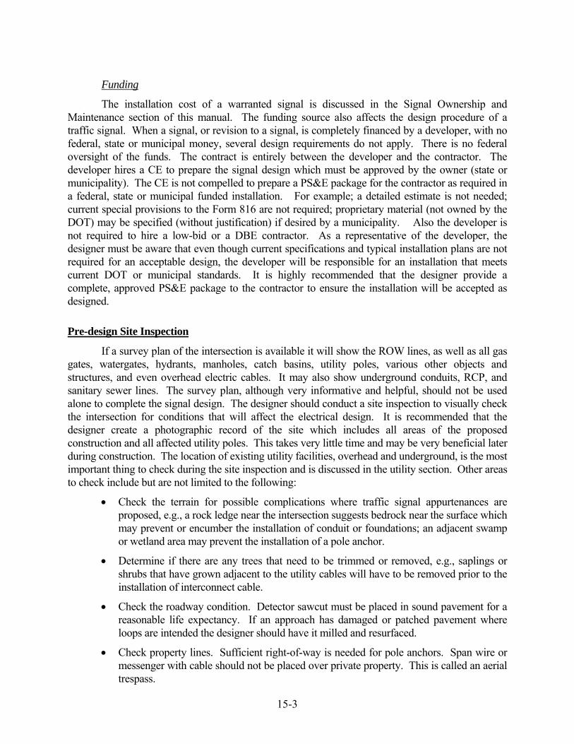
15-3
Funding
The installation cost of a warranted signal is discussed in the Signal Ownership and Maintenance section of this manual. The funding source also affects the design procedure of a traffic signal. When a signal, or revision to a signal, is completely financed by a developer, with no federal, state or municipal money, several design requirements do not apply. There is no federal oversight of the funds. The contract is entirely between the developer and the contractor. The developer hires a CE to prepare the signal design which must be approved by the owner (state or municipality). The CE is not compelled to prepare a PS&E package for the contractor as required in a federal, state or municipal funded installation. For example; a detailed estimate is not needed; current special provisions to the Form 816 are not required; proprietary material (not owned by the DOT) may be specified (without justification) if desired by a municipality. Also the developer is not required to hire a low-bid or a DBE contractor. As a representative of the developer, the designer must be aware that even though current specifications and typical installation plans are not required for an acceptable design, the developer will be responsible for an installation that meets current DOT or municipal standards. It is highly recommended that the designer provide a complete, approved PS&E package to the contractor to ensure the installation will be accepted as designed.
Pre-design Site Inspection
If a survey plan of the intersection is available it will show the ROW lines, as well as all gas gates, watergates, hydrants, manholes, catch basins, utility poles, various other objects and structures, and even overhead electric cables. It may also show underground conduits, RCP, and sanitary sewer lines. The survey plan, although very informative and helpful, should not be used alone to complete the signal design. The designer should conduct a site inspection to visually check the intersection for conditions that will affect the electrical design. It is recommended that the designer create a photographic record of the site which includes all areas of the proposed construction and all affected utility poles. This takes very little time and may be very beneficial later during construction. The location of existing utility facilities, overhead and underground, is the most important thing to check during the site inspection and is discussed in the utility section. Other areas to check include but are not limited to the following:
• Check the terrain for possible complications where traffic signal appurtenances are proposed, e.g., a rock ledge near the intersection suggests bedrock near the surface which may prevent or encumber the installation of conduit or foundations; an adjacent swamp or wetland area may prevent the installation of a pole anchor.
• Determine if there are any trees that need to be trimmed or removed, e.g., saplings or shrubs that have grown adjacent to the utility cables will have to be removed prior to the installation of interconnect cable.
• Check the roadway condition. Detector sawcut must be placed in sound pavement for a reasonable life expectancy. If an approach has damaged or patched pavement where loops are intended the designer should have it milled and resurfaced.
• Check property lines. Sufficient right-of-way is needed for pole anchors. Span wire or messenger with cable should not be placed over private property. This is called an aerial trespass.

15-4
• Note any objects which may not be on the survey plans and will affect the signal installation, e.g., trees, bushes, signs, walls, fences, beam rail, etc.
• Check the drainage system. If catch basins are present at the intersection there is a drainage system that must be avoided. The catch basins will be connected by reinforced concrete pipe (RCP). If not shown on a survey plan, the location of the RCP may be learned by looking into the catch basin. The RCP is deep enough so that the placement of conduit will not be affected, but foundations should not be placed over it. Foundations should not be placed adjacent to the catch basin structure either.
• Check the sewer system. The sewer system is usually owned by the municipality but may be owned by a utility company or private entity. Some sewer pipes are pressurized to force the waste uphill. The pipes are generally deep. Manhole structures are placed at regular intervals in the system for maintenance access. If two or more manholes, owned by the same company, are found it can generally be assumed the sewer runs between them. Foundations should never be placed over a sewer line. The sewer system owner should be contacted to either access their plans or to have an employee field locate the main sewer lines and laterals.
• If station numbers are not being used to locate the various traffic signal appurtenances, ensure they are tied off nearby existing physical objects such as a utility pole, catch basin, hydrant, edge of road or extended curb line.
• Check overhead utility facilities (see later guidelines, DPUC regulations, and NESC clearances in the utility section). Identify all existing utility cables that are attached to poles at or near the intersection. Measure and record the heights where attached to the poles and at mid span points where conflicts may be created with a traffic signal span wire or mast arm. Potential conflicts must be discussed and resolved later during the utility meeting.
Handholes and Cast Iron Junction Boxes
The NEC section 347-11 does not allow “more than four quarter bends (360 degrees total) between pull points...” in a conduit run. More than four greatly hinders the installation of cable. A cable pull point may be a handhole, cast iron junction box (CIJB) or a conduit body depending on the RMC installation method. The designer should consider all bends including up-sweeps into foundations and transitions from underground to surface conduit.
15-5
Handholes
The Department uses reinforced concrete handholes exclusively whenever a pull point is needed in an underground conduit system. Polymer/concrete, fiberglass or plastic handholes have proven to be not as strong or durable as reinforced concrete and are not used. Handhole placement is not as critical as foundations. They generally don’t need station numbers or ties on the plan. The contractor may field locate the handhole as needed to avoid utilities, driveways, or other objects. They may be placed in grass, sidewalk, or raised island areas but never in pavement within the travel way or shoulder area where vehicles and snow plows may damage them. Try to avoid a low area where rain water will drain and collect. If located on a slope, a bank adaptor should be used to keep the top flush with the surrounding earth. The standard cover is diamond plate galvanized steel with an AASHTO H20 (16,000 lbs., 9075 kg/wheel) vehicle load rating. Cast iron covers are available for certain conditions, e.g., in all sidewalk areas; as a municipal standard; or in an area with high vandalism. The cast iron cover is much heavier and is attached with recessed hex bolts. It is a separate item and each handhole where it is intended must be identified on the plan. There are two sizes of handholes that the Department uses. The smallest is 14 inches (355 mm) by 30 inches (760 mm), called Type 2, and is adequate for most pull points. If three or more conduits are terminated the designer should use the larger handhole which is 30 inches (760 mm) by 30 inches (760 mm). Try not to terminate more than six conduits in a handhole to facilitate future wiring changes.
Try not to use a pole or pedestal foundation as an intermediate cable pull point in a conduit run for the following reasons:
• Steel pole and mast arm bases have small handholes which make it difficult to pull cable.
• If a pedestal is knocked down by a vehicle, all conduit and cable in the base will likely be damaged and/or exposed.
Long straight runs of RMC for dilemma zone detection or interconnect should have
handholes for cable pull points. The handholes should be equally spaced a recommended distance of not less than 90 feet (27 m) or more than 180 feet (55 m) apart.
Cast Iron Junction Boxes
A cast iron junction box (CIJB) is commonly used as a pull point for RMC in structure or surface mounted on a bridge structure. The NEC Section 370-28 requires a certain size junction box depending on the size and direction of the conduit that is terminated. Straight pulls require a junction box length not less than eight times the diameter of the largest conduit. Angle or U pulls require a junction box dimension, from the conduit entrance to the farthest wall, six times the diameter of the largest conduit. A conduit body may also be used as a pull point for surface mounted RMC. There are several types known as a “C” or “L” fittings. It is smaller than a junction box; therefore if there are two or more cables in the RMC, the designer should use a CIJB. Junction boxes are estimated and paid as a separate item, not included in the cost of RMC like conduit bodies.
Electrical Conduits
The designer should review and be familiar with the NESC section 32, “Underground Conduit Systems” and several Articles of the NEC, Chapter 3, “Wiring Methods”.

15-6
Types
There are many types of electrical conduits available. Except loop detector sawcut wires, all underground cable that is used in a traffic signal installation is installed in rigid metal conduit (RMC). Direct buried cable is not allowed. Although acceptable by the NEC, rigid nonmetallic tubing or conduit such as polyvinyl chloride conduit (PVC) is also not used in a traffic signal installation by the Department. Intermediate metal conduit (IMC) and electrical metal tubing (EMT) is not used either underground or surface mounted. Occasionally there is a need for a short section of flexible raceway. Liquidtight Flexible Metal Conduit (LFMC) is used for this.
Fill
Chapter 9, Table 1 of the NEC restricts the fill of RMC, that contains more than two conductors, to 40% of the inside area. The NEC Chapter 9, Table 4, or the following table, Figure 15-1, may be used in determining conduit size. The most common size used in a signal installation is 2 inch (50 mm). The designer should total the cross sectional area of all cables intended for the conduit. For cable diameter and cross section area see Figure 15-2. In a new installation the conduit can be sized for the cables it will contain. Try not to use an odd size conduit. For example, if it is determined that a short section of 2 ½ inch (65 mm) conduit is needed for ≤ 40% fill, consider using two of a more common size such as 2 inch (50 mm). For a revision, it is very important that the designer verify that additional cable intended for an existing conduit will not exceed the usable area.
COMMONLY USED CONDUIT TRADE SIZE - R.M.C. TOTAL AREA – 100% USEABLE AREA - 40%
in mm in2 mm2 in2 mm2
1 25 0.88 567 0.35 225
1.5 40 2.07 1335 0.83 535
2 50 3.41 2200 1.36 877
2.5 65 4.86 3135 1.94 1250
3 75 7.41 4780 3.00 1935
3.5 90 10.01 6458 4.00 2580
4 100 12.88 8309 5.15 3322
Figure 15-1 Commonly Used Conduit

15-7
Installation Methods
There are several conduit installation methods common in a traffic signal design. Conduit can be surface mounted, placed in trench, under roadway, in a structure, under slope protection, or under railroad tracks. The design of the conduit system should facilitate the simplest and most direct wiring between foundations, utility poles and other appurtenances. Following are brief guidelines.
Surface
All RMC placed on a structure or on a utility pole is considered surface mounted. Conduit attached to a utility pole is commonly referred to as a “riser”. The number of traffic signal risers on a pole is limited to two, per the DPUC. Stand-off brackets should be used when: the riser size is greater than 2 ¼ inch (57 mm); the total number of risers on the pole exceeds 2; or there are stand-off brackets already in use on the pole. The pole custodian must be consulted regarding the use of stand-off brackets. A cable pull point is not needed in RMC on a pole. When necessary, RMC may be attached to an existing bridge structure. When crossing a bridge expansion joint a conduit expansion fitting is needed. Expansion fittings are included in the cost of the RMC. Use either a CIJB or a conduit body as a cable pull point. All stand-off brackets, expansion fittings, including the type, and all junction boxes should be identified on the plan.
In Trench
The NESC does not specify the depth of RMC in trench and under roadway. The NEC allows a minimum six inch (150 mm) depth. The Department however, requires a minimum 24 inch (600 mm) depth for all RMC in trench and under roadway. When bedrock is near the surface the designer should include the item “Rock in Trench Excavation 0 - 4 Feet Deep” (0 m - 1.2 m) to ensure the proper depth. Use a concrete handhole as a cable pull point.
Under Roadway
When a road crossing is necessary, try to cross perpendicular to the road. It is recommended to terminate the RMC in a handhole on either side of the road rather than in a foundation. Install a spare conduit for future use. Do not place a trench through an area where loops will be cut. If the trench is not patched properly the pavement will fail destroying the loops. When crossing roads constructed with reinforced concrete, the designer should include the item “Rock in Trench Excavation 0 - 4 Feet Deep” (0 m - 1.2 m) to pay for the extra work involved.
In Structure
Occasionally when a bridge is constructed it is necessary to include RMC in the parapet for interconnect or detector cable. Terminate the conduit in a handhole on either side of the structure. As with surface conduit on a structure, expansion fittings are needed when crossing an expansion joint. Use a CIJB as a cable pull point. The CIJB is paid as a separate item, not included in the cost of the RMC. All RMC, CIJBs, expansion fittings including the type, and handholes must be clearly shown on the bridge plans as well as the signal plan.
15-8
Under Railroad Tracks
When it is necessary to install RMC under railroad tracks use a minimum size of 2 ½ inch (65 mm) and terminate it in a large handhole, one on each side of the railroad right-of-way. It is recommended to also include a spare conduit under the tracks. The NESC rule 320A5 requires a minimum 50 inches (1270 mm) depth. The depth may either be increased when required by the RR owner or decreased where that depth is impractical. If reduced, the agreement of both parties is necessary.

15-9
Vehicle Detectors
Inductive Loop Detector (ILD)
Theory of Operation
The ILD system essentially consists of a coil of wire (loop) imbedded in the road, a lead-in cable (14/2) from the loop to the CA, and a loop detector amplifier. The ILD was developed and first used in the early 1960’s. The hardware and installation methods are continuously being improved but the operating principle is essentially the same. The amplifier transmits a low voltage AC signal to the loop at a certain frequency. The amplifier has an input capacitance (C) which establishes a resonant circuit using the loop inductance (L). When ferrous material passes over the loop, the inductance changes, de-tuning the resonant circuit which the amplifier detects as a vehicle. There have been many publications on ILD theory, practice, and installation and there have been many evaluations on ILD installation methods. The designer should be familiar with ILD characteristics such as the quality (Q) and sensitivity (S) and also the factors that affect them.
Splicing and Number of Turns
An ILD amplifier will operate more consistently and be more reliable when the loop circuit it is connected to has the correct inductance. The loop circuit consists of the loop detectors which are sawcut into the road and the lead-in cable. The loops circuit should be designed to provide an inductance of more than 70 microhenrys (μh). Optimum inductance is over 200 μh. The loop inductance also needs to be greater than the inductance of the lead-in cable from the handhole to the controller. The designer should calculate the inductance of the loops and the inductance of the lead-in cable. See the following loop and lead-in inductance formulas. If the loop inductance is less than the lead-in inductance, increase the number of turns. It should be noted that increasing the number of turns does not increase the Q or the S of a loop, only the inductance. A segmented loop detection zone is commonly used for presence detection. Each segment is cut to a handhole and spliced to the lead-in cable. When the segments are connected in series the inductance is additive. When the segments are connected in parallel the inductance is reduced. See the following inductance formulas. To insure the total inductance of a segmented loop arrangement is high enough, they should be spliced in series not parallel. A construction note is used to ensure the segments are spliced properly.

15-10
Loop Inductance (English) Loop Inductance (Metric) L loop = (P/4) (N2+N) L loop = (3.28P/4) (N2+N) Lead-In Inductance (English) Lead-In Inductance (Metric) L 14/2 = (0.24 μh/ft) (D) L 14/2 = (0.78 μh/m) (D) Where: L loop = Inductance of individual loop segment in microhenrys (μh). L 14/2 = Inductance of lead-in cable. P = Perimeter of individual loop segment, in feet or meters. N = Number of turns. D = Length of lead-in cable from splice in handhole to controller, in feet or meters.
LT = L1 + L2 + L3 etc. (Total Inductance of Segmented Loops Spliced in Series) LT = 1 ÷ [(1 ÷ L1) + (1 ÷ L2) + (1 ÷ L3) + (etc.)] (Total Inductance of Segmented Loops Spliced in Parallel) Where: LT = Total inductance of the segmented arrangement. L1, L2, L3 = Inductance of individual loop segments.
Sawcut
The ILD wire is sealed in the sawcut with a flexible, durable compound. The wire is manufactured specifically for this application in conformance with the International Municipal Signal Association (IMSA) specification 51-7. It has cross-linked polyethylene (XPE) insulation incased in a flexible polyethylene (PE) or polyvinyl chloride (PVC) jacket. The sawcut is exposed to extreme weather conditions, constant traffic, snow plows, and all kinds of vehicular fluids. It is the weakest link in the ILD system. When a loop is installed or replaced, one or more lanes of traffic must be closed. The designer should therefore keep the sawcut from the loop to the curb (known as the home run), as short as possible. Do not cut across opposing lanes of traffic unless it is absolutely necessary. Avoid sawcut on a bridge deck. There may be a waterproof membrane beneath the pavement that must not be damaged. Consider a non-intrusive detection system if a detection zone is necessary on a bridge deck.
Lead-In Cable
The lead-in cable (IMSA specification 50-2) is a shielded, twisted pair cable designed to eliminate induced voltage and electrical interference. It is shown on the plan as 14/2. All electrical connections in the ILD circuit must be sound. There should be no induced voltage, nor high

15-11
resistance shorts to ground in the lead-in cable. To minimize the possibility of electrical interference or a bad connection, all ILD lead-in cables are direct wired from the sawcut wires back to the CA. Splices are not allowed, other than connecting to the sawcut wires, and those are soldered. The 14/2 lead-in cables also do not enter the cable closure.
Video Image Detector System (VIDS)
As previously discussed in the Detection section, camera placement is crucial for the operation of a VIDS. The camera should be as high and as directly in front of the approach as possible. If the support structure (span pole or mast arm) is not in the optimal location or is not high enough, a bracket may be used to mount the camera. The designer must specify the length of the bracket. It is usually paid for as a separate item.
Each camera requires a power feed and a coaxial cable for the video return. A special siamese type cable, RG-59/U, is used which consists of a twisted pair of conductors and a coaxial conductor within one jacket. This is shown on the plan as “camera cable”.
Microwave Detector
Microwave detectors are also discussed in the Detection section. Essentially the RF system is self contained, with the transmitter, receiver, and output circuit in one unit. An amplifier in the CA is not needed. The detector requires 4 conductors, two for power, and two to provide an output to the CU. A shielded cable is not required. A 14/5 cable may be used although a four conductor (2 pair), 18 AWG, stranded, unshielded, PE insulation/jacket cable is recommended. It is shown on the plan as 18/2 pair.
Others
There are other types of detection systems available to the designer that are not commonly used by the Department in a traffic signal design. Some are more suitable for speed, volume, & classification data collection in an ITS rather than for intersection control. There are no specifications and typical installation drawings on the Department’s website. If requested by a municipality, the designer should thoroughly research the system and provide all the necessary electrical PS&E. Following are brief descriptions and guidelines for several alternate detection systems.
The ultrasonic detector is similar to the microwave in that the transmitter, receiver and output circuit are self contained in one unit. An amplifier is not needed. A 4 conductor cable is required for a power feed and the detection return. The difference is it operates at a lower frequency, ≈ 50 kHz. It will detect stationary vehicles providing presence detection. The disadvantages are it must be mounted either vertically (directly over the detection zone) or horizontally (side-fire) perpendicular to the vehicle path (3 feet to 5 feet (1.0 m to 1.5 m) high). It also has a limited range (22 feet (6.7 m)) and area of detection (5 feet (1.5 m) diameter).

15-12
Infrared detection systems sense the thermal energy in the far-infrared range (100+ GHz) of the electromagnetic spectrum. There are two types, active and passive infrared detectors. The active type transmits an energy beam to the detection zone and measures the reflected energy. It cannot provide presence detection. The passive type detects the thermal energy of a vehicle as compared to the surrounding road surface. It can provide presence detection. The location of the detector is critical for the proper operation. Because of their characteristics and location restrictions, the infrared detectors are more suitable for vehicle data collection in an ITS rather than intersection control.
Magnetic detectors (some known as magnetometers) are available in two types; the single-axis and the dual-axis sensor. They tune to the earth’s magnetic field and when the magnetic field is disrupted by the ferrous material in a vehicle, an output call is produced. The single-axis type will only detect vehicles moving more than ≈ 4 mph (6.4 kph) therefore will not provide presence detection. The dual-axis type will provide presence detection. The dual-axis sensor has a relatively small direction area. Several are needed to provide a large presence detection zone. The detector sensor(s) are pre-wired by the manufacturer with a short length of cable which is spliced to a 14/2 detector lead-in cable. A magnetic detector amplifier is also required in the CA.
A self powered vehicle detector (SPVD) is a dual-axis type of magnetometer that does not require a physical connection to the CA. It is battery operated and sends the vehicle call back to the CA over RF. An antenna is required at the intersection, and a receiver/amplifier is required at the CA.
An acoustic detector senses the high frequency noise produced by moving vehicles tires. It cannot provide presence detection. The sensor is side mounted, 25 to 40 feet (7.6 m to 12.2 m) high and is capable of monitoring up to 5 lanes. The primary application is speed, volume & classification data on an expressway. It has little or no application for intersection control detection.
Traffic Signal and Pedestrian Wiring
The Department has standardized the type of cables used in a traffic signal installation. These are shown in Figure 15-2 as well as the common use and the size (diameter and cross section area). Cable used to feed traffic and pedestrian signals has solid conductors (not stranded), straight-lay, rated at 600 volt (IMSA spec 19-1 or 20-1). It is identified on the plan by the American Wire Gauge (AWG) of the conductors and by the number of conductors. For example, a five conductor cable with each conductor #14 AWG is shown as 14/5. Most 120 VAC output circuits are wired with #14 AWG conductors. The designer should use a cable with enough conductors to ensure at least one spare at each signal assembly. List cables on the plan per size in descending order, e.g., 14/21, 14/15, 14/12.
Span wire signals are generally not direct wired back to the CA. A cable closure is mounted on the span wire and connected to the CA with a 21 or 25 conductor cable. Each span mounted signal assembly is then wired to the cable closure by a separate cable. Splices outside the cable closure are not allowed.
Mast arm mounted signals should be direct wired back to the CA. Splices are not allowed in the arm. A splice in the mast arm base it is not recommended.
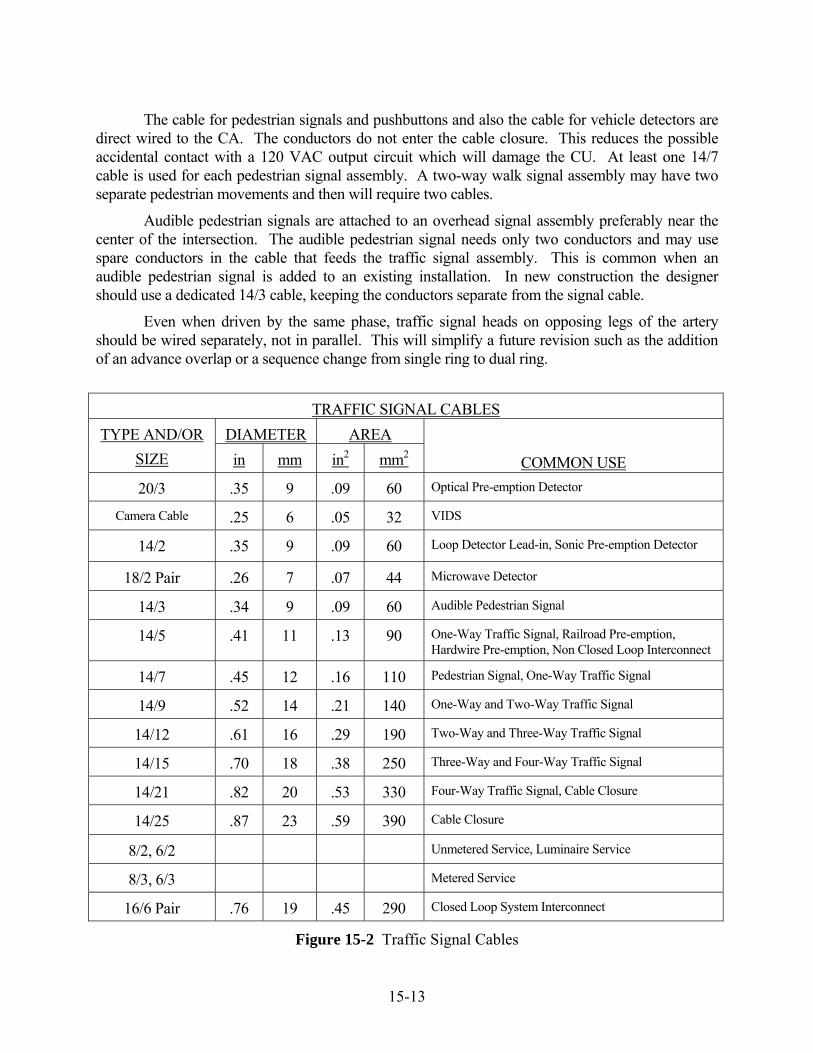
15-13
The cable for pedestrian signals and pushbuttons and also the cable for vehicle detectors are direct wired to the CA. The conductors do not enter the cable closure. This reduces the possible accidental contact with a 120 VAC output circuit which will damage the CU. At least one 14/7 cable is used for each pedestrian signal assembly. A two-way walk signal assembly may have two separate pedestrian movements and then will require two cables.
Audible pedestrian signals are attached to an overhead signal assembly preferably near the center of the intersection. The audible pedestrian signal needs only two conductors and may use spare conductors in the cable that feeds the traffic signal assembly. This is common when an audible pedestrian signal is added to an existing installation. In new construction the designer should use a dedicated 14/3 cable, keeping the conductors separate from the signal cable.
Even when driven by the same phase, traffic signal heads on opposing legs of the artery should be wired separately, not in parallel. This will simplify a future revision such as the addition of an advance overlap or a sequence change from single ring to dual ring.
TRAFFIC SIGNAL CABLES DIAMETER AREA TYPE AND/OR
SIZE in mm in2 mm2
COMMON USE 20/3 .35 9 .09 60 Optical Pre-emption Detector
Camera Cable .25 6 .05 32 VIDS
14/2 .35 9 .09 60 Loop Detector Lead-in, Sonic Pre-emption Detector
18/2 Pair .26 7 .07 44 Microwave Detector
14/3 .34 9 .09 60 Audible Pedestrian Signal
14/5 .41 11 .13 90 One-Way Traffic Signal, Railroad Pre-emption, Hardwire Pre-emption, Non Closed Loop Interconnect
14/7 .45 12 .16 110 Pedestrian Signal, One-Way Traffic Signal
14/9 .52 14 .21 140 One-Way and Two-Way Traffic Signal
14/12 .61 16 .29 190 Two-Way and Three-Way Traffic Signal
14/15 .70 18 .38 250 Three-Way and Four-Way Traffic Signal
14/21 .82 20 .53 330 Four-Way Traffic Signal, Cable Closure
14/25 .87 23 .59 390 Cable Closure
8/2, 6/2 Unmetered Service, Luminaire Service
8/3, 6/3 Metered Service
16/6 Pair .76 19 .45 290 Closed Loop System Interconnect
Figure 15-2 Traffic Signal Cables
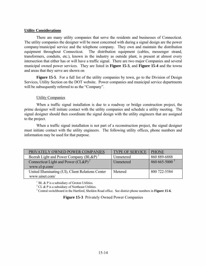
15-14
Utility Considerations
There are many utility companies that serve the residents and businesses of Connecticut. The utility companies the designer will be most concerned with during a signal design are the power company/municipal service and the telephone company. They own and maintain the distribution equipment throughout Connecticut. The distribution equipment (cables, messenger strand, transformers, conduits, etc.), known in the industry as outside plant, is present at almost every intersection that either has or will have a traffic signal. There are two major Companies and several municipal owned power services. They are listed in Figure 15-3, and Figure 15-4 and the towns and areas that they serve are shown on
Figure 15-5. For a full list of the utility companies by town, go to the Division of Design Services, Utility Section on the DOT website. Power companies and municipal service departments will be subsequently referred to as the “Company”.
Utility Companies
When a traffic signal installation is due to a roadway or bridge construction project, the prime designer will initiate contact with the utility companies and schedule a utility meeting. The signal designer should then coordinate the signal design with the utility engineers that are assigned to the project.
When a traffic signal installation is not part of a reconstruction project, the signal designer must initiate contact with the utility engineers. The following utility offices, phone numbers and information may be used for that purpose.
PRIVATELY OWNED POWER COMPANIES TYPE OF SERVICE PHONE Bozrah Light and Power Company (BL&P) 1 Unmetered 860 889-6888 Connecticut Light and Power (CL&P) 2
www.cl-p.com/ Unmetered 860 665-5000 3
United Illuminating (UI), Client Relations Center www.uinet.com/
Metered 800 722-5584
1 BL & P is a subsidiary of Groton Utilities. 2 CL & P is a subsidiary of Northeast Utilities. 3 Central switchboard in the Hartford, Sheldon Road office. See district phone numbers in Figure 15-6.
Figure 15-3 Privately Owned Power Companies
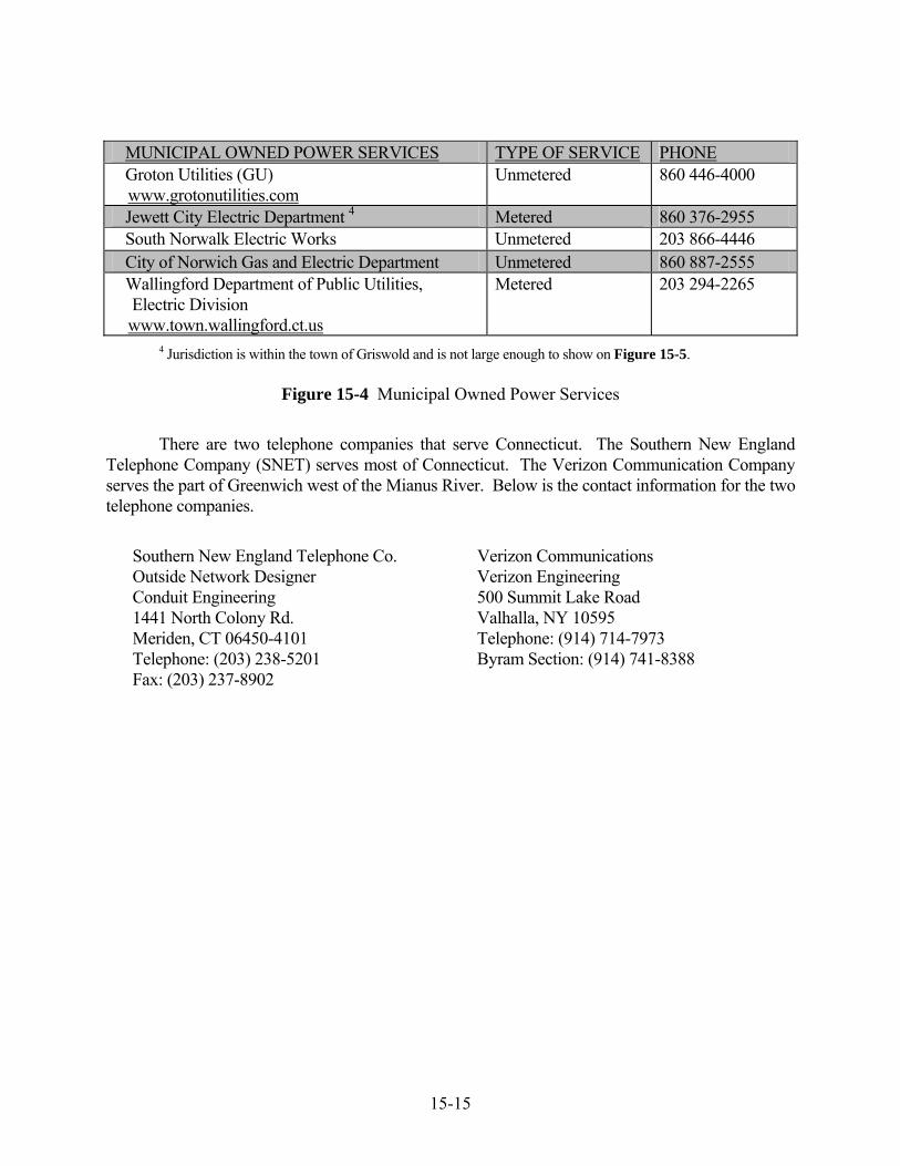
15-15
MUNICIPAL OWNED POWER SERVICES TYPE OF SERVICE PHONE Groton Utilities (GU)
www.grotonutilities.com Unmetered 860 446-4000
Jewett City Electric Department 4 Metered 860 376-2955 South Norwalk Electric Works Unmetered 203 866-4446 City of Norwich Gas and Electric Department Unmetered 860 887-2555 Wallingford Department of Public Utilities,
Electric Division www.town.wallingford.ct.us
Metered 203 294-2265
4 Jurisdiction is within the town of Griswold and is not large enough to show on Figure 15-5.
Figure 15-4 Municipal Owned Power Services
There are two telephone companies that serve Connecticut. The Southern New England Telephone Company (SNET) serves most of Connecticut. The Verizon Communication Company serves the part of Greenwich west of the Mianus River. Below is the contact information for the two telephone companies.
Southern New England Telephone Co. Verizon Communications Outside Network Designer Verizon Engineering Conduit Engineering 500 Summit Lake Road 1441 North Colony Rd. Valhalla, NY 10595 Meriden, CT 06450-4101 Telephone: (914) 714-7973 Telephone: (203) 238-5201 Byram Section: (914) 741-8388 Fax: (203) 237-8902

15-16
Figure 15-5 Power Company Jurisdiction in Connecticut

15-17
As shown in Figure 15-5, Northeast Utilities serves the majority of towns and cities in Connecticut. Northeast Utilities has divided their service area into 13 districts, each with engineering offices. See Figure 15-6 for a list of the districts and the phone numbers.
DISTRICT OFFICE AND LOCATION PHONE
1 Stamford/Greenwich 626 Glenbrook Road, Stamford 06904
203 352-5489
2 Norwalk Tindall Avenue, Norwalk 06851
203 845-3484
3 Newtown/New Milford 20 Barnabus Road, Newtown 06470
203 270-5806
4 Waterbury 250 Freight Street, Waterbury 06702
203 597-4246
5 Torrington/Falls Village 69 Water Street, Torrington 06790
860 496-5278
6 Cheshire/ New Britain 705 West Johnson Avenue, Cheshire, 06410
203 271-4837
7 Simsbury 34 Hopmeadow Street, Simsbury 06070
860 651-2446
8 Madison 135 New Road, Madison 06443
203 245-5408
9 Middletown/East Hampton 49 Randolph Road, Middletown 06457
860 638-2206
10 Hartford 400 Sheldon Street, Hartford 06106
860 280-2445
11 Tolland/Enfield 1654 King Street, Enfield 06083
860 871-3560
12 New London 12 Masonic Street, New London 06320
860 447-5750
13 Willimantic/Danielson 1270 Main Street, Willimantic 06226
860 456-5027
Figure 15-6 Northeast Utilities District Offices and Locations
Use of Utility Poles
As previously discussed in the Support Structure sub-section of this manual, one or more utility poles may be used to support a span wire. There are certain regulations and clearances that the designer must observe when this is done. See DPUC Regulations 16.243 “Construction and Maintenance Standards Governing Traffic Signals Attached to Public Service Company Poles”. Prior to discussing the regulations, clearances and guidelines, there is some background information on utility pole construction the designer should know.

15-18
The utility company that owns the pole is considered the custodian. The custodian is responsible to replace the pole due to age, damage or other reasons. Metal letters identifying the custodian and metal numbers identifying the pole number are nailed onto the pole.
Important information regarding each pole is branded onto the pole by the pole supplier. The brand contains a code identifying the species of tree, the type of preservative used, year of treatment, the circumference (class), and length. The length and class may be helpful to the signal designer when discussing a proposed span attachment with the utility companies. The brand, on poles up to 50 feet in length, is located 10 feet (2.1 m) from the butt end. Figure 15-7 shows typical pole data.
POLE
HEIGHT SETTING DEPTH
COMMUNICATION MAX HEIGHT 1
POWER MIN HEIGHT 1
35’ 6’ 21’ 2” 24’ 6” 40’ 6’ 23’ 8” 27’ 0” 45’ 6’ 6” 25’ 11” 29’ 3” 50’ 7’ 28’ 2” 31’ 6”
1 Height may be adjusted depending on the mutual ownership agreement.
Figure 15-7 Utility Pole Data
A utility company other than the custodian may purchase space on the pole for their facilities which results in joint ownership. An agreement is reached between the power company and the communication companies as to the percentage of available space that each may use. There is generally more than one utility company on a pole.
Section 16-243-8 of the DPUC regulations describes the clearance requirements for conductors attached to a utility pole. To illustrate this, see Figure 15-8. This is a typical pole construction with a traffic signal span attachment. NESC rule 235 requires a 40 inch (1.0 m) clearance between the highest communication cable and the lowest power (supply) cables. This is considered a “communication worker safety zone”. If these clearances are not present and cannot be met by adjusting the existing cables, consider replacing the pole with a taller one. The designer should be familiar with certain exceptions to the regulations. In the interest of safety, the designer is also obligated to correct any existing clearance violations that are found on poles that will be used in the design. Below are some options if the proper clearances cannot be provided.
• Request relocation of the affected utility cables.
• Request reconstruction of the pole top with out-rigged cross arm away from span attachment or a pole top extension.
• Replace one or more utility poles with taller poles.
• Alter the span design to avoid creating a conflict.
Utility pole construction depends on a variety on factors which cannot be discussed here. All reconstruction must be agreed upon by both the power company and the telephone company.

15-19
Typical Utility Pole Construction
Figure 15-8 Typical Utility Pole Construction
Transformer
Highest communication cable. Usually CATV or fiber system. May be traffic signal interconnect cable if in a system or a messenger strand carrying detector cable. 1
Traffic signal span wire.
Lowest communication cable. Usually Telephone Company.
Minimum 40 inches above highest communication cable.
Height above ground determined by Telephone Company.
Minimum 12 inches below lowest power cable.
Communication cables spaced 12 inches apart.
Strain insulator.
Brand identifying height and class of pole. Approximately 4 feet above ground.
Setting depth
No Scale
Distribution Circuits. Spacing, clearances, and construction type determined by Power Company.
Lowest power company attachment. Usually secondary.
1 See DPUC regulations 16-233. Only one gain is allowed. Either detector messenger or interconnect cable, not both.
Anchor
Down Guy

15-20
A dilemma zone design will require vehicle detection a considerable distance from the intersection. If an ILD system is desired, the designer has a choice to install the lead-in cable, from the intersection to the detectors, either overhead or underground. If underground, there will be a high cost for trenching and RMC in-trench for the lead-in cable. Therefore the designer should always consider the use of a messenger strand between two or more poles to support the detector cable overhead. The clearances in NESC rule 235 govern here also. There must be a minimum 40 inches (1.0 m) between power and communication cables. The proposed messenger must be attached a minimum 12 inches (0.3 m) above the highest communications cable and 40 inches (1.0 m) below the power cable. This will place the cable in the communications gain. It is important to note that the traffic signal span wire is considered a power cable. If a span wire is present, it must be attached a minimum 12 inches below the other power cables.
When a span wire is attached to a utility pole, an anchor and down-guy is generally required to offset the load on the pole. In accordance with DPUC regulation 16-243-6, the power company will determine the guying strand size and location. Occasionally the pole in question will have primary cables and communication cables in three or more directions. In that case, the power company may determine that an anchor for a traffic signal is not needed. The distance between the pole and the anchor, called the “lead”, depends on the available ROW and conditions behind the pole. A down-guy for a traffic signal typically has 15 feet to 20 feet (4.5 m to 6.0 m) of lead. If ROW is not available, an easement should be pursued by the designer. If other conditions, such as a wetlands or a significant down slope prevent a normal anchor, a sidewalk anchor may be used. The sidewalk anchor needs less lead distance. If there is insufficient ROW even for a sidewalk anchor, head-guys to adjacent poles (pole-to-pole guy) may be used to bisect and transfer the load. The adjacent poles may then be anchored and guyed. See Figure 15-9. A tree should never be used as a traffic signal anchor. As well as determining the guying requirements, the power company will also provide and install the anchor, guy and necessary hardware.
Figure 15-9 Pole-To-Pole Guy
Pole-To-Pole Guy

15-21
Overhead
The proposed span wire must have the proper clearance to other cables within the intersection. Section 233 of the NESC addresses mid-span vertical and horizontal clearances. A span wire supporting signal cable is classified by the NESC as a 230C3 cable. Normally the span is high enough not to conflict with communication cables and low enough not to conflict with power cables. Unusual conditions such as low primary conductors or a high span wire will require corrective action. The designer should calculate the height of the proposed span where it will cross other cables. Anticipated conflicts should be discussed during the utility meeting. For safety reasons a 10 foot (3 m) clearance to primary cables is desired. The suspended traffic signals must also have sufficient horizontal clearance to communication cables to prevent contact during high winds. A minimum 4 feet (1.2 m) is recommended.
A mast arm signal design usually does not introduce the utility clearance concerns that a span wire design does. There are no attachments to poles and, if the mast arm structure is not the combination type (with a luminaire), it is not near the primary cables. The major concern of a mast arm signal design is the heights of communication cables where the arm will cross through. A mast arm with fixed-mounted signals is usually at the same elevation as communication cables, between 18 feet and 19 feet (5.5 m and 5.8 m) above the road. DPUC Section 16-243-8 requires a minimum 12 inch (0.3 m) clearance to communication cables. The designer should always measure the height of the cables and compare this to the estimated height of the proposed arm. A cross section diagram showing the arm and all communication cables is helpful. If a potential conflict is found, the designer should request that the cables be raised or lowered. If one or more utility poles must be replaced to provide the clearance, the designer may consider a free-swinging signal design. A free-swinging signal design allows the arm to pass above the communication cables. The arm is usually between 20 feet and 23 feet (6.0 m and 6.9 m) above the road. As in a span wire design, the suspended signals and signs should not be near communication cables. A minimum 3 feet (0.9 m) of horizontal clearance is needed to prevent contact during high wind conditions.
Interconnect installation guidelines, including the use messenger and cable extension brackets, are discussed in the Interconnect section.
Beneath Transmission Lines
Alternating current flowing through a conductor will create an electrical field in the space around the conductor. The field from a distribution voltage circuit has little effect on an adjacent traffic signal. Transmission lines however, have extremely high voltage and current. The effect of an electrical field from transmission lines may damage electronic equipment and be hazardous to people.
15-22
There are certain conditions the designer must consider when a traffic signal is located beneath or adjacent to power company transmission lines. The electric field created by the high voltage in the lines (up to 345 kv) will induce a voltage in any conductive material nearby. The induced voltage level depends on the transmission line voltage, the proximity of the object to the lines, and the orientation of the object to the lines, e.g., a span wire or mast arm parallel to the lines will receive a higher charge than one perpendicular. Normally the induced voltage is dissipated by draining the current to ground, however material that is not grounded properly will develop a discernable electrical charge.
Traffic signal appurtenances, including conduit, should not be placed within 50 feet (15 m) of a transmission support structure. Consult with the transmission line owner regarding the signal design. Include in the design all recommended material and actions to reduce, and eliminate if possible, the induced voltage. This may include additional ground rods, bonding wire, or a ground grid. In addition include all recommended installation procedures such as keeping a mast arm assembly grounded during erection.
Underground
The location of underground utilities is critical in the vicinity of a proposed foundation of a controller, steel pole, or mast arm. The most common utilities encountered are natural gas, water, and sewer lines. In urban or downtown areas, power and communication conduit systems are common. The cost to relocate existing utilities preclude that option unless absolutely necessary. A roadway reconstruction project however, may allow the relocation of utilities to accommodate a pole foundation. Otherwise all underground utilities should be avoided.
There are many clues that indicate the presence of underground utilities that the designer should be aware of during the field survey. Manhole covers (power and communication) or gas vent pipes indicate a vault which may be quite large. Primary risers, communication risers, gas gates, water gates, AT&T and SNET identification posts, a recently patched trench, are a few other visual indications. The field survey should not be restricted to just the intersection under design. An inspection of the road and sidewalk area a short distance each side, may also provide evidence to the location of underground utilities.
The Call-Before-You-Dig (abbreviated as CBYD or sometimes incorrectly as CBUD) system does not locate underground utilities for an engineer during the design stage. Occasionally however, old mark-outs will still be visible at an intersection from a recent excavation. Old mark outs should not be relied on to accurately locate underground utilities. They may be used as a guide only. The CBYD system uses different color paint for each type of utility. See the CBYD color code table, Figure 15-10. If the location of underground utilities is suspected in the area of a proposed pole or mast arm foundation, the utility company should be contacted to determine the exact location. Test pits may also be done to establish the exact location of an underground utility.

15-23
CALL-BEFORE-YOU-DIG COLOR CODE COLOR UTILITY Red Electric Power Lines and Conduits Yellow Gas, Petroleum Products, Steam, Other Hazardous Liquids Blue Water Green Sewer Orange Communication Cables and Conduits, Fiber, Cable TV Purple Radioactive Material Pink Temporary Survey White Proposed Excavation
Figure 15-10 Call-Before-You-Dig Color Code
Utility Meeting
Section 16-243-9 of the DPUC regulations briefly describes a field utility meeting. The purpose of the meeting is to inform the utility companies of the proposed work and identify and resolve all conflicts between the traffic signal and utility facilities. Prior to the meeting the designer should prepare and be ready to provide to each utility engineer the following information and/or document.
• A preliminary design plan showing the proposed location of steel poles or mast arm assemblies with ties or if available, station number and offset.
• The estimated height of any span attachments to utility poles.
• The estimated load (tension) that the span will place on a utility pole.
• The estimated height of the span wire or mast arm where it will cross through existing utility cables. A cross-section sketch is recommended.
• The estimated electrical load of the traffic signal.
• The party responsible for the electrical energy to operate the traffic signal.
• The reimbursable percentage of all utility work and the party responsible for payment.
• The construction schedule.
This manual cannot discuss all possible utility situations the designer may encounter. The following subjects should be used as a guideline when conducting a utility meeting.
• Electric service, type (metered or unmetered) and source.
• Proposed steel pole/mast arm assemblies location.
• Span wire attachment to poles and the necessary anchors and guys.
• Potential mid-span crossing conflicts with utility cables.
• Conduit attachment to poles and the need for stand-off brackets.
• Telephone service source.

15-24
• Messenger and detector cable attachment to poles for arterial detection.
• Interconnect cable attachment to poles.
The designer must leave a copy of the preliminary plan with the utility company engineer showing all utility pole attachments, span wire crossing points (with estimated heights), risers, anchors, etc.. The designer should also request from the power and telephone company a cost estimate (by letter or e-mail) for the work they will perform.
It is recommended to complete a report-of-meeting document. The report should list all subjects discussed (even if there is no action required), including all agreements, responsibilities and resolutions to anticipated conflicts. The designer should send a copy to all interested parties (whether in attendance or not) along with a copy of the final signal design. If personnel changes are made before construction begins (by the utility company or the signal designer) the report-of-meeting will be very beneficial to the replacement engineer.
Electric Service
Source
The most convenient and most common service source is a utility pole or a mid-span tap to secondary cable. Occasionally an underground vault or secondary conduit system may be more convenient. All power company service requirements should be discussed and agreed upon during the utility meeting. Although the DPUC construction standards, section 16-243-6, allow line and load conductors in the same conduit, the Division of Traffic Engineering does not. All service (line) conductors to a traffic control cabinet must be contained in a dedicated RMC with no other cables. The service is never direct buried. The size of the conduit is usually 2 inch (50mm).
Traffic Signal Requirements
The electrical service needed to operate a traffic signal is 120 VAC. Because low power LED traffic and pedestrian indications are now standard, the load will never exceed 2000 watts even at a large intersection. Normally #8 AWG, Type SE (Service Entrance), copper conductors is adequate and is the Department’s standard. Copper clad aluminum or aluminum conductors are not used. Occasionally #6 AWG or larger conductors are used to reduce line losses where the CA is a considerable distance from the service source. If this is the case, Chapter 9, Table 9, of the NEC or the table in Figure 15-11 may be used to calculate anticipated voltage loss in the service cable.
CONDUCTOR SIZE
AC RESISTANCE PER 1000 FEET (305 M)
# 8 AWG 0.78 Ohms # 6 AWG 0.49 Ohms # 4 AWG 0.31 Ohms
Figure 15-11 Service Conductor Resistance
15-25
Metered
The electric service to a traffic signal may be either metered or unmetered depending on the serving Company’s regulations. See Figure 15-3 and Figure 15-4. A metered service provides an accurate monthly bill as well as a method of monitoring when the load has been increased, decreased or disconnected. The Company installs, owns, and maintains the line-side conductors of a metered service, therefore the designer must ensure the line conductors are installed directly from the source to the meter enclosure. They should not enter the CA prior to entering the meter enclosure. The meter requires 240 volts to operate therefore three conductors are used and shown on the plan as 8/3. On the load-side of the meter, only one side of the 240 volt line is connected to the main breaker in the CA. The type of service, "metered", must be indicated on the signal plan. When a metered service is needed from CL&P, a 3 inch (75mm) conduit is installed from the source to the meter enclosure. A 2 inch (50mm) RMC is recommended in Jewett City, UI and Wallingford Electric areas.
Unmetered
An unmetered service is preferred by most Companies because typically the load of a traffic signal is consistent month-to-month and there is no need to install, maintain, and read a meter. It is the most common type and also the least expensive to install. It is billed at a different rate and the customer is obligated to notify the Company, in writing, of all load changes within 30 days. The signal owner also owns the conduit and service conductors up to the point where they are connected to the utility company’s secondary service. Only two conductors are needed and are typically shown on the plan as 8/2. The type of service, “unmetered”, must be indicated on the signal plan.
Request for Service/Power Letter
For all new, relocated, or removed services, the Company requires a Request for Service form to be completed and submitted prior to scheduling the work. This document contains specific information about the traffic signal such as location, equipment description, estimated load, applicant, and customer to be billed. The Department uses a program known as the Signal Inventory to generate the Request for Service forms. The Signal Inventory was created to compile pertinent information on all traffic signals. An important function of the Signal Inventory program is to generate a standard Request for Service form, recognizable by all power companies, municipalities, and customers in Connecticut.
The program also generates the Power Letter which is a document that is similar to the Request for Service but also has the account number, meter number (if metered service), and the effective billing date. After the traffic signal installation or revision is completed, the Power Letter is sent to the Company with a copy to the customer.

15-26
All traffic signals that are on a state route are listed in the Signal Inventory data base. The data base is continuously updated by Department employees as new signals are installed and as existing signals are revised. Request for Service forms and Power Letters for traffic signals on state routes are generally completed by a Division of Traffic Engineering, Electrical Engineer. Consultant Engineers do not have access to the Signal Inventory. Intersections not on State routes and that do not have a six digit location number, are not in the data base. The Department cannot generate a request for service or issue a power letter for these signals. The necessary documents for service and subsequent billing updates are the responsibility of the Consultant Engineer or a municipal official.
Telephone Service
Occasionally a traffic signal will need a telephone service to communicate with an operation center, a maintenance office and/or a traffic engineering office, e.g., a closed loop interconnect system master. The closed loop interconnect system currently in use by the Department requires a dial-up voice grade connection at the master. A data circuit at each location, which was required for the UTC System, is no longer needed. The designer should discuss the telephone drop with the serving telephone company during the utility meeting. Below are design guidelines.
An auxiliary termination cabinet (ATC) is used to terminate the telephone cable. It allows access to the cable by the Telephone Company technician without opening the CA door. It is attached to left side of the CA when facing the door. A municipal owned installation may not require an ATC.
The telephone company technician will install the service, therefore a dedicated conduit (usually 1 ½ inch (38 mm)) directly from the utility pole or manhole to the ATC should be shown on the plan. The service (as all communication circuits) shall not be placed in conduit with other utilities, on a span wire, or in a steel pole along with signal cables. The dedicated conduit should also have a pull rope for the telephone company technician.
If it is a State owned system, a telephone service request must be completed and forwarded to the Office of Property and Facilities. The request contains information such as the location, pole number, coding for payment, and DOT contact person. If it is a municipal system, a town official or representative makes arrangements with the telephone company for service.
Powered Signs
A warning sign may either have one-section indications attached that flash yellow or may be internally illuminated. Solar powered flashing signs are not used by the Department as a permanent installation and are also not discussed here. Solar powered flashing signs however may be used as a temporary warning device. All permanent signs that have flashing signals or that are internally illuminated require a 120 VAC supply either from the CA or directly from the local utility company. The type of sign that is desired will dictate the electrical design. Variable Message Signs (VMS) or Changeable Message Signs (CMS) used in Connecticut’s IMS, are not part of a traffic signal installation and are not discussed here. Below are the different types of signs and the design guidelines.

15-27
Alternate Flashing Signals on Warning Sign
Type A: One-way signal sections that flash alternately are attached to a road-side, post mounted warning sign to draw attention to the message. The signals flash 24 hours a day. This type may or may not be associated with a traffic signal. For maintenance and billing purposes this type of flashing sign is considered a separate location, even if associated with a nearby signalized intersection. It should have its own intersection number, secondary service, protected disconnect (flasher cabinet), and account number.
Type B: Similar in construction to Type A, this warning sign is placed in advance of a traffic signal. For the design/operation of this type of sign refer to the “Flashing Message Sign” chapter of this manual. The warning sign message is usually “When Flashing Stop Ahead”. It is powered by and controlled by the traffic controller. It should be connected to the CA with a 14/5 cable. It is considered part of the traffic signal therefore a separate intersection number, flasher cabinet, secondary service and account number are not needed.
Type C: A side mounted mid-block, pedestrian crossing sign is a special installation; privately or municipally owned. The signals flash when actuated by a pedestrian. If on a State road the installation should have its own intersection number, secondary service, and account number.
Internally Illuminated Warning or Advisory Sign
These are usually rigid mounted overhead (on a support structure or bridge overpass), or side mounted on a support structure. If span mounted they should be tethered to reduce movement and ensure proper alignment. The message or symbol is “blanked-out” and cannot be seen until it is illuminated. The symbol or message is illuminated by either fiber optics or by LEDs so power consumption is less than 300 watts. The operation of an internally illuminated sign is generally associated and directly related to the operation of the traffic signal.
Type D: The most common internally illuminated sign is the flashing stop-ahead sign. It is a blank-out design so that the words “Stop Ahead” cannot be seen until the sign flashes. For the design/operation of this type of sign refer to the “Flashing Message Sign” chapter of this manual. It should be connected to the CA with a 14/5 cable. It is considered part of the traffic signal therefore a separate intersection number, flasher cabinet, secondary service and account number are not needed.
Type E: A changeable lane use sign may occasionally be associated with a traffic signal. If one or more is needed, the designer must specify the legend and/or symbol and size. Each message will require a separate conductor. A 14/5 cable is generally sufficient. The sign is considered part of the traffic signal therefore a separate intersection number, secondary service and account number is not needed.
Type F: A “No Left Turn” and/or “No Right Turn” sign is sometimes used at intersections that have railroad pre-emption to restrict vehicles from turning onto the tracks. These are placed on an approach where the turn is normally allowed. This type of sign is also considered part of the traffic signal therefore a separate intersection number, secondary service and account number is not needed.
15-28
Interconnect
Type
Interconnect is the medium over which signals in a system communicate. The time base system will not be discussed in this section since it does not require an interconnect. There are three types of interconnect that are predominant in Connecticut. Most widely used is a shielded, twisted pair, copper cable. The other types are fiber optic cable and spread spectrum radio frequency (RF). The Department primarily uses twisted pair cable for data transfer in a closed loop system. Municipalities have chosen to use copper cable, fiber, RF or a combination of the different types. A non closed loop system such as a master/slave does not require data transfer therefore does not require a shielded, twisted pair communication cable. A signal cable may be used to transmit the yield command from the master to the slave(s).
As previously discussed in the “Signal Systems” chapter of this manual, the designer should determine the type of system and if closed loop, the interconnect type. Signals added to an existing system should have the same type as the existing system unless there are circumstances or a physical obstruction which makes another type more practical, e.g., an RF type will avoid cable installation over a movable bridge. The electrical characteristics and design guidelines of each type are discussed below.
Twisted Pair Cable
There are currently 95 State owned, arterial closed loop systems in Connecticut which include over 840 intersections. The communication method is full duplex over shielded, twisted pair copper cable. If installed overhead on utility poles the trunk circuit is usually a figure 8 type cable. The support strand is molded into the polyurethane jacket above the conductor cable so that a cross section view of the cable resembles a figure 8. Most 12 pair trunk circuits have 6 pair reserved for municipal use. The installation and splicing method is easy and requires no specialized training. Modems or patch panels are not needed as in a fiber or RF system.
The twisted pair cable is classified as communication cable and when installed overhead on utility poles, must be installed in the communication space directly above the highest communication cable which is usually a Cable TV cable. A 12 inch (0.3m) clearance to the highest communication cable and a 40 inch (1.0m) clearance to the lowest power company attachment (usually secondary service) is required. Refer to NESC Table 235-5. A cable extension bracket is available in various lengths, which may be used to obtain the clearance and avoid a pole change. The designer must review each pole with the utility companies and determine any make-ready work necessary to meet these clearances. The interconnect attachment points and necessary utility work should be documented in a table and included either in the special provisions or on the plans. See the example in Figure 15-12. When more than a few poles are used, an interconnect plan should be developed. This plan will include but not be limited to showing all intersections, utility poles, cable closures, drop cables, and all pertinent construction notes.

15-29
Fiber Optic Cable
Several municipalities in Connecticut use fiber optic cable for interconnect systems. Currently the Department does not. There are several types of fiber optic (FO) cables available. The fiber may be installed overhead on utility poles or underground in a duct system. If installed overhead, the designer has several installation options and, as always, should consult with the municipality regarding the installation method. The FO cable may be supported by rings from a steel messenger strand; may be wrapped to a steel support strand; may be self supported by a synthetic aramid fiber strand; or may be placed in an aerial duct system. There are advantages and disadvantages to each method. The FO cable is dielectric i.e. it does not conduct electricity and the communication contained in the cable is not affected by stray or induced voltage. However if a steel support strand is used the strand has to be bonded and grounded in accordance with the NESC section 9 and 215.
The NESC rule 230F allows FO cable to be classified as either supply or communication and therefore can be installed on the pole in either the power space or the communication space. If installed in the power space the FO cable must have the proper clearance to communication facilities. If installed in the communication space, the FO cable must have the proper clearance to supply facilities. The guidelines previously discussed for the twisted pair cable regarding clearances, attachment list, and interconnect plan, apply for the FO cable as well.
Signal Cable
Although rarely used, a non closed loop system such as the master/slave, may be the most appropriate for a particular condition. Signal cable may be used as interconnect. It is not a communication circuit and it is not necessary to keep it separate from other power cables. It may be installed on utility poles supported by a messenger strand. The clearances and installation guidelines are the same as detector cable which is previously discussed in the “Use of Utility Poles” subsection. The detector cable and interconnect may share the same gain and be supported by the same messenger.

15-30
INTERCONNECT CABLE ATTACHMENT LIST
Town: Route: Direction: Sheet ____ of _____
POLE NUMBER
PROPOSED ATTACHMENT POINT COMMENTS
SNET 1234 1 foot (0.3m) above CATV A, C, D SNET 1235 1 foot (0.3m) above CATV B SNET 1236 1 foot (0.3m) above CATV I SNET 1237 Attachment point vacated by CATV F SNET 1238 Attachment point vacated by CATV E, F CL&P 9876 Extension Bracket 1 Foot (0.3m) above CATV CL&P 9875 Extension Bracket 1 Foot (0.3m) above CATV D CL&P 9874 Attachment point vacated by CATV F, H CL&P 9873 1 foot (0.3m) above CATV H CL&P 9872 1 foot (0.3m) above CATV H SNET 2345 Attachment point vacated by SNET E SNET 2346 1 foot (0.3m) above SNET G SNET 2347 1 foot (0.3m) above SNET D GU 876 1 foot (0.3m) above CATV GU 875 Attachment point vacated by CATV E, F GU 874 1 foot (0.3m) above CATV GU 873 Extension Bracket 1 Foot (0.3m) above CATV A, C, D, J COMMENTS Install interconnect cable on the street side of pole unless otherwise specified as Field Side or Dead End. A Dead-End interconnect cable with thru bolt. B Field Side. C Refer to Typical Installation Sheet, Bonding and Grounding Requirements, Item 1. D Refer to Typical Installation Sheet, Bonding and Grounding Requirements, Item 2. E SNET to lower 1 foot (0.3m). F CATV to lower 1 foot (0.3m). G SNET to replace pole. H CL& P to replace 3 spool open secondary rack with triplex. I CL& P to raise secondary 1.5 feet (0.5m). J Groton Utilities to replace pole.
Figure 15-12 Interconnect Cable Attachment List

15-31
Structural Design for Span Poles
The designer must specify a steel pole that will provide an attachment height high enough to allow a signal clearance of at least 16 feet (4.8 m) over the road. As when determining the mast arm assembly pole height and attachment point, the designer must consider the elevation of the proposed foundation in relation to the road surface. The Department has a list of standard steel poles based on length, strength and bolt circle. See the span wire design guidelines in the “Signal Support Structures” section. As well as determining the height, the designer must calculate the horizontal tension (Design Tension) on the pole to confirm that the standard design load-at-yield is adequate. Below is the accepted method of calculating the Design Tension.
SIGNAL SECTION WEIGHT OUTSIDE DIMENSION
8 inch (200 mm) 7.5 lb. 33 N1 10 inches 250 mm 12 inch (300 mm) 15 lb. 67 N 14 inches 350 mm
SIGNAL HARDWARE WEIGHT LENGTH 1 Way Hanger 10 lb. 45 N 12 inches 300 mm 2 Way Hanger 20 lb. 90 N 12 inches 300 mm 3 Way Hanger 25 lb. 110 N 12 inches 300 mm 4 Way Hanger 30 lb. 135 N 12 inches 300 mm Span and Cable 1 lb./ft 14.5 N/m 1 Newton = 9.81 X Kilogram

15-32
SIGNAL ASSEMBLY LOADS
W1 = Signal Wt. + Hardware Wt. + [(Cable Wt.) (S1 + S2/2)] W2 = " " + " " + [( " " ) (S2 + S3)/2] W3 = " " + " " + [( " " ) (S3 + S4)/2] W4 = " " + " " + [( " " ) (S4 + S5)/2] W5 = " " + " " + [( " " ) (S5/2 + S6)]
Moments Pole A = W1 (S1) + W2 (S1 + S2) + W3 (S1 + S2 + S3) + W4 (S1 + S2 + S3 + S4) + W5 (S1 + S2 + S3 + S4 + S5) Reaction Pole B = Moments Pole A ÷ (S1 + S2 + S3 + S4 + S5 + S6)
Moments Pole B = W5 (S6) + W4 (S6+ S5) + W3 (S6 + S5 + S4) + W2 (S6 + S5 + S4 + S3) + W1 (S6 + S5 + S4 + S3 + S2) Reaction Pole A = Moments Pole B ÷ (S1 + S2 + S3 + S4 + S5 + S6)
Check that the sum of the Loads equals the sum of the Reactions. W1 + W2 + W3 + W4 + W5 = Reaction Pole A + Reaction Pole B
Low Point = Reaction Pole B - W5 - W4 - W3 - etc. until the answer is a negative number.
The last W subtracted is the Low Point. Or Reaction Pole A - W1 - W2 - W3 - etc. until the answer is a negative number. The last W subtracted is the Low Point.

15-33
Design Tension = 2.5 T The Load-at-Yield of the selected pole must be greater than the calculated design tension. Attachment Height = 17 feet (5.2 m)* + Sag + Total height of largest signal or signal at low point. The pole height should be at least 1.5 feet (0.5 m) more than the attachment height. * Desired clearance of signals over road. Acceptable clearance is 16 to 18 feet (4.8 to 5.5 m).
Check that the Horizontal Tension on pole A equals the Horizontal Tension on pole B. For the example below, assume the Low Point is W3. Sag = 5 % of span length = (0.05) (S1 + S2 + S3 + S4 + S5 + S6) Horizontal Tension Pole A = [(Reaction Pole A) (S3 + S2 + S1) - W2 (S3) - W1 (S2 + S3)] ÷ Sag = T Horizontal Tension Pole B = [(Reaction Pole B) (S4 + S5 + S6) - W4 (S4) - W5 (S4 + S5)] ÷ Sag = T

15-34
Plans, Specifications and Estimates
Plans
The Division of Traffic Engineering has traffic signal typical installation detail sheets that are available on the DOT website. The plans illustrate the construction methods for State owned traffic signals that the Contractor must follow. Familiarity with these is beneficial to the designer as well as the contractor. It should be noted that several municipalities have installation methods that are different than these. The designer must ensure the typical sheets are appropriate for the particular project and current. Details that are contradictory for the project should either be deleted or crossed through and labeled “NIC” (Not In Contract).
Specifications
A traffic signal is installed in accordance with the Department’s “Standard Specifications for Roads, Bridges and Incidental Construction” (currently the Form 816), and supplemental specifications. The supplemental specifications are issued twice a year, January and July and will eventually be included in the next edition of the Standard Specifications. In addition, special provisions to the Form 816 are often created to cover a special item, type of work, or to update an obsolete specification. Many special provisions that the Division of Traffic Engineering has developed and used are on the DOT website. These may be used when applicable or may be modified to address a special installation, e.g., when approved, proprietary material is specified for a municipality. When using a special provision the designer must ensure all work and material has a method of measurement and a basis of payment. The specification must be as clear and concise as possible. If ambiguous or contradictory to other contract documents, a change during construction may be necessary or a claim against the State may be filed, resulting in unnecessary costs.
The use of federal funds for full payment of proprietary material is generally not allowed. Federal-Aid Policy No. 23 CFR 635.411 “Material or Product Selection” describes when federal money may be used. If full payment is desired by the eventual owner, it must be formally requested and approved as described below. If not approved, the owner may choose to contribute to the contract the difference in cost between the proprietary product and the generic product.
• In letter form, submit the request for use of proprietary material.
• Address the request from the eventual owner or CE representing the owner, to the Manager of Traffic Engineering.
• List all desired proprietary materials. Include all pertinent information such as model number, revision number, etc.
• Clearly justify the need for proprietary materials.
• The request will be evaluated by Traffic Engineering and a recommendation forwarded to the Engineering Administrator or FHWA depending on project oversight.
• Once approved or denied, the owner will be notified of the decision.
• Upon approval, the manufacturer’s name and product identification will be used in the specifications or on the plans.

15-35
If not approved, either the specification will remain generic or a cost sharing agreement may be pursued. If cost sharing is pursued, the difference in cost between the proprietary product and the generic product is determined. Historical unit price information is used to determine the cost of the generic product. The cost of the proprietary product is provided by the requestor.
Estimates
A list of established item numbers with descriptions and also a list of weighted-unit-prices, both in PDF form, is available on the DOT website.
A proposal estimate must be prepared which lists the total of all traffic signal items, quantities, and estimated prices. The proposal estimate is generated through the Bid Management Information System (BMIS). It is used to develop the item bid list. The estimated prices for a specific project are confidential and should not be divulged to any party outside the Department. A Detailed Estimate Sheet (DES) is also prepared in which the items are assigned to each intersection rather than a section of roadway defined by station numbers. As previously stated, these estimates are not necessary for privately funded signals designed for a development. They are necessary for publicly funded projects where the contract is awarded to the lowest bidder. The DES, along with the intersection plan and special provisions, provides each bidder a reasonably accurate representation of the work required at each intersection. A blank DES is available on the DOT website.
The following information will aid the designer in preparing a DES:
• The CADD cell library is TR_ESTIMATE.cel
• The naming convention is TR_EST_XXXX_XXXX.dgn, where the x’s are the project number.
• Organize all item numbers in numerical order.
• The item name should perfectly match the proposal estimate and visa versa.
• When applicable, edit the top field to indicate “Federal Aid Participating”.
• Do not include items that the pay unit is estimated “EST”.
Example: Trafficperson (State Police Officer) pay unit is EST, therefore not listed. Trafficperson (Uniformed Flagger) pay unit is Hr., therefore is listed.

15-36
Miscellaneous
Location Numbering System
The location numbering system was developed for traffic signals to eliminate the confusion that frequently occurs when an intersection is described by local street names. The system has since been expanded to include a variety of State owned and maintained installations on a State maintained road or highway. See Figure 15-13 for the types of installations that have location numbers and the number range of each. A traffic signal location number (known as an intersection number) is a six digit, two part number, e.g., 123-234. The first three digits represent the town number (001 through 169). The next three are the location number. The numbering system has been extremely helpful in many ways such as organizing engineering/maintenance records, and updating utility bills. The Signal Inventory data base previously discussed in the Electric Service section, is where intersection numbers are created and updated.
TYPE OF INSTALLATION LOCATION NUMBER RANGE
Traffic Signal or Powered Sign1: State Owned on State Road Municipal Owned on State Road2
XXX-201 through 499
Traffic Signal: Municipal Owned not on State Road3
XXX-901 through 999
Weigh-In-Motion Site XXX-701 through 799 Remote Weather Information System XXX-701 through 799 Incident Management System: Variable Message Sign (VMS) VMS and Surveillance Camera Site Vehicle Detection Site
XXX-500 through 599 XXX-701 through 799 XXX-701 through 799
Cathodic Protection System XXX-701 through 799 Other XXX-
1 Powered signs driven by the controller do not require an intersection number. 2 Includes interstate and other expressway OFF ramps. 3 Only intersections that have an interstate and other expressway ON ramp and intersections that have railroad
pre-emption. Otherwise location number is not assigned.
Figure 15-13 Location Numbering System
15-37
Uninterruptible Power Source
With the use of LED indications, the power requirements of a typical traffic signal are much less than when incandescent lamps were used. A properly Volt/Amps (VA) rated uninterruptible power source (UPS) will operate a traffic signal for a short time if there is an outage and will also provide another level of protection from spikes and surges on the service line. The Department has determined that the infrequent occurrence of a power outage does not justify the additional cost of installation and maintenance of an UPS. The Department does not allow a UPS on State owned signals. If a municipality desires a UPS at a critical intersection, the designer must develop specifications, such as VA rating and whether the UPS is “on-line” or “stand-by”, to suit the application and the owner’s requirements. The municipal officials must be aware of the future ownership and maintenance responsibilities. A UPS device contains batteries that periodically must be replaced. Also if the CA were to be struck by a vehicle, hazardous material (battery acid) may be released from the UPS device.
Illumination
Normally the roadway lighting system is separate from the traffic signal. The lighting system may be owned by the State, municipality or the serving power company. If there is no lighting system, spot roadway lighting may be desired and included in the traffic signal installation. Occasionally the location of a steel pole or mast arm assembly is such that a luminaire may be attached, eliminating a light standard. This design is preferred because it reduces the number of roadside fixed objects. The designer must consider several issues when including a luminaire in the signal design and should consult with the Department's Illumination and Electrical Section (Division of State Design).
• If the proposed luminaire will be part of an adjacent lighting system, determine the
owner. Luminaries owned by the power company cannot be attached to steel poles or mast arms.
• Determine the type of luminaire. The type should match the adjacent type, e.g., it is not recommended to install a high-pressure-sodium type within a mercury-vapor type system.
• Determine the bracket length. When a luminaire is attached to a support structure, a combination structure is used which includes the luminaire bracket. The bracket length should be indicated on plans in the support structure data table.
• Determine the service source. If the party responsible for the traffic signal electricity is different than the party responsible for the illumination electricity, service should not be from the controller cabinet. If underground, a separate conduit from the pole base to the service source is needed. If a splice in an underground illumination circuit is required, do not make it in the pole base.

15-38
Use of Construction Notes
A construction note should be included whenever clarification or a specific instruction is needed for the contractor. Notes are especially helpful when a signal is revised and there is mixture of new and existing material. There is a list of common construction notes in the CADD cell library on the DOT website. As in all written instructions or specifications, the notes should be as clear and concise as possible to avoid ambiguity. The active-imperative voice is recommended. The notes are directed at the contractor therefore the phrase “The contractor shall” is not needed. An example is: “Splice segmented loops in series per lane”. Notes may also be used to identify work that is to be done by others such as the installation of a utility pole by CL & P. Do not add notes for work that is obvious. Try not to clutter up plans with repetitious notes. If it would be helpful to link the note with a specific area on the plan, use a letter within a hex symbol next to the note and place the symbol at the location on the plan.
Example: “ Install cast iron handhole cover”.
Use of Technical Notes
Technical notes are used by the designer to clarify or define an unusual operation. When the CA is fabricated to the specific intersection plan, the technical notes provide information that is necessary to the technician. The most common are non-standard skip notes.
Scrap and Salvaged Material
When an existing signal is revised or upgraded, the contractor is directed to remove all abandoned traffic signal equipment. The abandoned material is considered either scrap or salvage. Scrap material is not reusable, has little or no salvage value, and must be disposed of by the Contractor. Salvage material may be reusable or has a salvage value, e.g., controller unit or copper wire. The contractor is directed to return salvage material to the owner. The Department has predetermined which material is scrap and which is salvage from a State owned traffic signal. The types of material are listed in the special provision to the Form 816, Section 11.18. When a municipal owned traffic signal is revised or upgraded the designer must consult with the town official to determine what material will be returned to the town and where it should be delivered. The text of the special provision to the Form 816, Section 11.18 should be modified to account for the town owned salvage material.
Most of the scrap and salvage material is within the intersection and is apparent to the designer and to the Contractor. There may be material that is not apparent, e.g., handholes for dilemma zone detectors; pressure detector frames; messenger with detector, interconnect or pre-emption cable attached to utility poles; RMC risers; anchors and guy wires. The designer should review the existing plan of record and, during the field survey, identify any material that will be abandoned and may be overlooked by the contractor. It is recommended to list this material in a construction note and, if necessary, link to the location on the plan with a hex symbol.
X
16-1
16 SIGNAL PLAN LAYOUT
The following pages provide design guidelines and general considerations for completing the signal plan form. The designer should refer to specific sections of the design manual for detailed design information. Blank signal plan forms are available on the DOT's website.
The sequence and timing section follows two different formats, one for sequential phasing and one for dual ring or quad phasing. For sequential phasing, fill in the phases working from left to right. Phase 1 is typically reserved for an artery advance, phase 2 for the artery through movement and phase 3 for an exclusive pedestrian phase. For dual ring phasing or quad operation, pay particular attention to the phase numbers with respect to which movement is typically controlled by that phase.
The numbering of signal faces should always be split so that each leg of the intersection has different numbered signal faces. When designing a full or half quad type signal, number the signal faces to correspond to the phases. For ease of trouble shooting and/or inspecting a traffic signal, always number the signal faces with the corresponding phase where possible (this is not possible in two phase operation).
Drafting guidelines and requirements are detailed in the Drafting Guidelines section of this manual.

16-2
Figure 16-1 Typical Phase Assignments

16-3
Figure 16-2 Sequence and Timings

16-4
Figure 16-3 System Information Blocks

16-5
Figure 16-4 Design Information Blocks

16-6
Figure 16-5 Traffic Control Signal Plan Office Record

16-7
Figure 16-6 Construction Notes Section

16-8
Figure 16-7 Intersection Layout
17-1
17 SIGNAL SYSTEMS
Signal systems should be designed to move platoons of traffic on arterial roadways and/or for queue control. Emphasis should be placed on the development of a wide "green band" to favor the flow of the arterial street traffic while not restricting the flow of other traffic. Sometimes the volume of traffic entering or leaving the system from side streets may exceed the through volume on the arterial. Every effort should be made to define the origin and destination of traffic in the system and to be sure that the major flows are incorporated into the progression.
Signal System Coordination Types
A closed loop system is a method of coordinating several signalized intersections with a master. The master is interconnected to and communicates periodically with each local controller (usually transmitting the correct time of day). The master also communicates with a central office computer. Once the system timing plan is initially programmed and stored in the local controllers the master serves as a communication hub between the central office and the locals. When necessary, for example due to an incident or an extreme weather condition, the on-street master receives coordination instructions from an operator at the central office and in turn downloads the information to the local controllers. The master also receives pertinent information from the local controllers and transmits that to the central office. An operator, at the central office, has the ability to revise the system timing plan, monitor the status of each local controller, extract vehicle volume and occupancy data, pre-emption history, malfunction history, and even change local controller phase timing.
A time base system is a method of coordination in which the system timing plan is typically programmed in an external device known as a time clock/time base coordinator (TC/TBC). This device is located in each controller cabinet. The system timing plan may also be programmed directly into the local controller. There is no interconnect or communication between intersections or to a central office. The time base electronic clock is very accurate and once programmed, supplies the coordination information such as system cycle length, offset, yield point, max 2 selection, permissive period, etc.
An open loop system is a method of coordinating several signalized intersections with a master. As with a closed loop system, the master serves as a hub and communicates periodically with the local intersections. The system timing plan resides in the local controllers. The master also receives pertinent information from the local controllers. In an open loop system however, there is no communication with a central office computer. The system timing plan is either manually programmed or downloaded from a laptop computer into the master. To revise the system parameters or extract data from the local controllers the operator must go to the master and connect a laptop. This type of system is seldom used by the Department.

17-2
The closed loop and the open loop systems have the ability to operate in a traffic responsive mode, which is defined in the Glossary. The Department has determined that a traffic responsive operation does not improve system efficiency more than a well designed time-of-day (TOD) operation, and in fact may be detrimental to the system concept. A traffic responsive operation requires considerable effort to design, monitor and support. All system detection must be accurate and impeccably maintained. A malfunctioning detector or a disabled vehicle on a detector may cause the master to transition to an undesirable pattern. In addition, the master may transition back and forth unnecessarily between two timing patterns if the arterial volumes fluctuate between critical threshold volumes. A transition period is usually 15 minutes. All systems in use by the Department currently operate in a TOD mode. The pattern settings and the time of day that the patterns change is pre-determined by a traffic engineer. Once programmed, the pattern in use is selected depending on the time of day and the day of week.
Procedure for Determining System Type
The procedure for determining the type of coordination for a new signal system or a revision to an existing signal system is a five stage process aimed at providing a signal system that is efficient and expandable as well as consistent with the Department's Congestion Management System. This procedure is not generally necessary for the addition of new signals within the confines of an existing system but may be necessary for new signals proposed at the end of an existing system.
Traffic Engineering Analysis
1. Define area to be controlled and determine current and long-term needs, keeping in mind proposed new roadway facilities and possible future signal locations and future signal systems.
2. Determine if area to be controlled has been established as an alternate route or has the
potential to be an alternate route. An alternate route is a route established by the Department to be used by motorists in the event of an incident on a freeway. The list of official alternate routes for Connecticut is maintained by the Highway Operations Section of the Office of Maintenance.
3. Determine the following transportation characteristics of the area:
a) Arterial volume to capacity ratio (V/C). b) Route characteristics: - major commuter route - major commercial area - major recreational area c) Number of traffic peaks and directional flow. d) Frequency of special events.

17-3
Systems Analysis
1. Define system parameters:
a) Number of intersections controlled. b) Number of timing plans using computer programs such as Synchro, Passer II,
Transyt-7 or other techniques. c) Number of system sections - determine if the defined system should be broken down
into sub-systems. 2. Define methods of controlling system timing:
a) Time of day. b) Manual - (manual override) ability to implement special system timing plans from a
remote site.
Selection of Alternative Systems
1. Initial Screening: If the proposed system limits lie within an alternate route, select a closed loop system, disregard the signal system work sheet and proceed to the approval stage.
2. Signal System Work Sheet:
a) Fill out the signal system work sheet. b) Select the system whose point total corresponds with the range of total points
indicated below: Type of System Point Range Time base coordination 5 - 14 Closed Loop System 15 - 23
Obtain Input from the Highway Operations Section of the Office of Maintenance Upon completion of the work sheet, the originating unit shall send a Signal System
Concurrence Sheet to the Office of Highway Operations indicating the Division of Traffic Engineering's preliminary recommendation regarding the type of system and requesting that office's review and comment. Accompanying the concurrence sheet should be a section of road map indicating the limits of the system and the individual signalized intersections, a completed signal system work sheet and any other supporting data that may be appropriate.
Obtain Approval of the Selected Type of Signal System Upon the return of the Signal System Concurrence Sheet from the Office of Highway
Operations and consideration of any comments, the originating unit shall forward the final recommendation for the type of signal system and all supporting information to the Manager of Traffic Engineering for approval.

17-4
Signal Coordination System Selection Work Sheet
Parameter
Weighted Measure
Parameter Point Total
1 2 3 Number of System Sections
1
2 - 4
Greater than 5
Number of Timing Plans
3 or less 4 - 6 Greater than 6
Alternate Route Potential
No Potential Slight Potential Great Potential
Method of Controlling Signal Timing
Time of Day Time of Day and Manual
Arterial V/C Ratio .50 to .70 .71 to .80 > .80 Parameter
Weighted Measure
0 3 Route Characteristics All Other Roadways Major Commuter Route
Major Commercial Area Major Recreational Area
Need for Surveillance Not Needed Needed for Monitoring and Data Collection
Number of Intersections 2 – 20 Greater than 20
TOTAL Type of System Point Range Time base Coordination 5 - 14 Closed Loop System 15 – 23
Figure 17-1 Signal Coordination System Selection Work Sheet

17-5
Signal System Concurrence Sheet
L TOWN: ROUTE: O C DESCRIPTION: A T I O N S T TRAFFIC ENGINEER: DATE: R WARRANT SHEET ATTACHED: YES: NO: A MAP ATTACHED: YES: NO: F SUPPORTING DATA ATTACHED: YES: NO: F COMMENTS: I C TYPE OF SYSTEM RECOMMENDED: PRINCIPAL ENGINEER: O SYSTEMS ENGINEER: DATE: P E COMMENTS: R A T I O CONCUR WITH RECOMMENDED SYSTEM: N YES: NO: S PRINCIPAL ENGINEER: A APPROVED AS RECOMMENDED P P MANAGER OF TRAFFIC ENGINEERING R YES: NO: O V A L Return to Unit ________
Figure 17-2 Signal System Concurrence Sheet

17-6
Signal System Design
Arterial control is concerned with controlling signals along an arterial highway so as to give major consideration to progressive flow of traffic along that arterial. It is desirable to develop a time relationship between the master location and each intersection along the artery. The green should be displayed at an intersection sufficiently in advance of the arrival of a major platoon, to clear vehicles that may be stopped and to allow the platoon to continue without stopping.
When developing a timing plan, it is preferable to have vehicles arrive at each intersection too early rather than too late. Vehicles arriving a little bit early wait a lot less time than vehicles arriving late. Early arrivals can avoid stopping by adjusting their speed. Vehicles that are a bit late are tempted to run the yellow light or increase their speed.
The timing plan of a system consists of three elements: splits, offsets and system cycle lengths. The splits must be determined for each individual intersection in the system and may vary from intersection to intersection. The split is the segment of the intersection cycle length allocated to each phase that may occur. The offset is defined as the time difference from the reference line of the system to the beginning of the artery yellow interval at each intersection. The reference line is usually chosen as the beginning of the artery yellow interval at the master. Determination of an optimum system cycle length(s) is the key to any efficient signal system. The intersection cycle length(s) for each signal in a system must be the same or a multiple of one another. Methods for determining optimum intersection cycle length and phasing were discussed earlier.
The engineer should consider progression before finalizing the phasing for the individual signalized intersections when designing signals that are going to be included in a signal system. It is important to have safe and efficient operation at each intersection but there are design options that should be considered. In lieu of quad left-turn phasing for protected left-turns on the artery, the designer may find that a lead-lag design would provide better progression and still provide a safe and efficient operation. Therefore, after determining the lane arrangements, signal phasing, cycle length and the number of timing patterns for each intersection, the designer should perform a preliminary arterial analysis including a time-space diagram.
There are many computer programs available to assist in arterial progression analysis. The designer should explore system cycle lengths that are compatible with the optimum intersection cycle lengths. A review of this information should indicate if any changes to the phasing are appropriate for improved arterial operation. This process is important because signal phasing for the individual intersections can limit the ability to provide good progression through the system.
Another factor in the design of an individual intersection that may become evident during the arterial analysis is that some intersection cycle lengths may not be compatible with the system cycle length during some timing plans. These intersections should be designed to have flexibility to operate full-actuated during these time periods. The same consideration should be given to signals that do not have programmed flash when most of the other signals in the system flash during nighttime hours. Therefore, this process is important because it may show the need to revise signal phasing and/or the type of signalization (full vs. semi-actuated) to reduce delay and improve traffic flow along the corridor.

17-7
A system may be designed to favor directional flow during peak hours. This may require a reduction in the flow in the opposite direction. The determination of level of service (LOS) and associated measure of effectiveness, as discussed in Chapter 16 of The Highway Capacity Manual, may be used to evaluate different system alternatives.
Intersections that are disruptive to the progression of the platoon may be put on flash when their operation is not essential or may run free. Left-turns from shared lanes may obstruct the flow of the platoon. Corrective actions such as turn bays or special phasing should be considered. Normally it is desirable to reserve 50 % or more of the cycle length for the artery green.
In a dual ring sequence, phase 2 is typically assigned to the artery movement in one direction and phase 6 to the artery movement in the opposite direction. In order to standardize the phasing of signals in a system the designer should assign the northbound or eastbound artery movement to phase 6 and the southbound or westbound artery movement to phase 2.
Another function that systems have is the ability to set different permissive period settings for each timing pattern. This function allows the designer to increase the permissive period during off peak hours to reduce the delay to drivers on side streets and protected left-turn phases. During normal daytime hours a 5% permissive period is typically used. At night when traffic volumes are low, the permissive period could be increased to 20% or higher. Assuming a 60 second cycle, a 20% permissive period would be 12 seconds. If a vehicle arrives within the first 11 seconds after the yield point, there would still be time to service the minimum side street time without affecting the system progression.
Time-Space Diagrams
The time relationship between intersections in an arterial system can be shown graphically by developing a time-space diagram. The time-space diagram is a technique for evaluating a proposed timing pattern and determining intersection offsets from a common reference point. The first step in developing a time-space diagram is to gather data, such as intersection spacing, traffic volumes (including turning movements), traffic flow variations and speed limits. Once the data has been obtained, the following steps are taken:
1. Analyze the traffic flow variations by direction on the artery, and determine the probable
number of timing patterns required. 2. Using Synchro or HCS traffic software, input the applicable data and configure the lane
arrangements, timings and cycle lengths to obtain an acceptable LOS. This should be done for each of the timing patterns to be developed. Once this is done, create a time-space diagram for each timing pattern.
3. Conduct a graphical analysis to determine offsets for each of the desired timing patterns as follows:
4. Plot a reference signal band for the left most signal in the system. • Draw a progression speed line beginning at the start of the artery green interval at the
left most signal. The slope of the speed line will represent the desired progression speed (posted speed or less, expressed in feet per second (m/sec)).
• Draw a horizontal reference line, preferably through the beginning of the artery yellow interval of the signal that will be the master location.

17-8
• Manipulate the signal bands i.e. offsets for all the signals as required, to obtain an equal bandwidth for each direction of flow.
• The results of the preceding step will provide a timing pattern with a comparable green band in both directions commonly used during off-peak times. If one direction should be favored as an AM peak or PM peak, another pattern should be created. The offsets are adjusted to provide a wider green band for that direction. Progression in the opposite direction may be compromised however.
Traffic entering the arterial system from side streets may be accounted for in the time-space
diagram as part of the through band or have its own separate band. The volume of traffic included in progressive flow of traffic that may enter from side streets should be determined and accounted for in the evaluation of various signal designs. All too frequently the "fine tuning" of a system in the field involves the neglect of this traffic during design.
A signal system that cannot be made to work on paper will not work in the field. Fine tuning in the field to solve progression problems is a hectic and confusing experience. Fine tuning is exactly that…fine tuning. It should consist of minor timing revisions and not wholesale changes in operation.
For signals in a coordinated system, a time/space relationship should be demonstrated by whatever techniques are in use at the time, including computer programs.

17-9
Figure 17-3 Time Space Diagram Example

17-10
Closed Loop System Design
All State owned closed loop coordination equipment must comply with the applicable sections of the current edition of the DOT Functional Specifications for Traffic Control Equipment. It is recommended that the designer become familiar with these specifications which describe the minimum system parameters. The following operational information and guidelines apply to systems purchased under the specifications in effect as of the publication date of this manual. Because of the continual advances in technology and software upgrades, earlier (and future) DOT systems may operate in a slightly different manner. If there is any question regarding the operation of a particular system, or the features available, the designer should request advice from the signal lab. The design of a municipal system should comply with municipal specifications therefore the following information and guidelines may not apply.
When signals are under closed loop control the max settings in the local controllers are inhibited. By inhibiting the max timing for phases in the local controllers, the engineer can develop splits for the system to assign different max timings for each phase for each timing pattern. The designer can use the max 1 and max 2 settings for times when the signal is running under programmed free operation. Usually the designer would only run full-actuated signals under free operation. Under free operation the system only monitors the local signal controller's operation and all the timings come from the settings on the local signal controller.
The following is provided to clarify what type of operation results when there is either a communication or coordination failure in closed loop systems. This can help the engineer better understand and assess complaints regarding signal operation. If there is a communication failure such as a break in interconnect between master and local, the signals time the programmed splits and offsets but with no communication. In the case of a coordination failure such as a prolonged period of double cycling, signals default to max 1 timings (free operation). The designer should ensure that this is considered in determining the max 1 green time settings for all signal phases.
One feature that closed loop systems have, in a sequential operation, is the ability to allocate unused time from a non-artery phase to subsequent phases via the Unused Time Feature (UTF). The UTF can be used for a sequential operation where there is a quad operation in the other side of the barrier in use. If the use of this feature is being contemplated in a sequence other than sequential, please check with the signal lab for compatibility. The designer can allow the time to be allocated to subsequent phases of operation or allocate to the artery phase all unused time from the non-artery phases. If this option is selected it will be shown as a technical note stating: "UNUSED TIME TO BE REALLOCATED". Utilizing this feature can be beneficial in many cases but it should be pointed out that this feature doesn't allow selection of the phase(s) to which the unused time is distributed. An example would be where there may be two side street phases, each side street having its own phase. The designer may want to consider having the low volume side street phase come in first. That way if the first side street phase is skipped or gaps out, any unused time could be used by the other side street if there are sufficient calls. Since any unused time may be allocated to following phases, the designer should avoid fixed advances. If there is a fixed advance where there are different splits for each timing plan (the advance is in max recall) all the unused time from the preceding phases would be assigned to the advance phase. It should be pointed out that the designer could have a fixed advance and still allow allocation of unused time as long as the advance only has one timing instead of different splits for each timing plan (the advance would be min recall in this case).

17-11
The allocation of unused time (UTF) gives the designer flexibility and therefore strong consideration should be given to its use. If this function is used there should be a technical note on the plan to inform anyone reviewing the signal's operation that any unused time can be allocated to subsequent phases.
In a closed loop system, cycle lengths do not always have to be increased to accommodate exclusive walk phases. If an exclusive walk phase is provided, the designer should take into account how many times an hour it is expected to be called during each timing pattern. The designer can put the full time in the data base for the walk if that phase is expected to come in frequently during the period that timing pattern is in effect.
If it is expected to come in infrequently, the designer may decide to assign a zero split for the walk phase. If the walk phase comes in, the time for the walk phase will be taken from the artery green at the start of artery green. The signal may double cycle if there isn't sufficient time in that phase to satisfy the minimum green for the artery before the yield point. This practice is not preferred because the walk takes all its time from the artery phase. The designer should add a technical note "Signal may double cycle if pedestrian timing called during patterns x, x, x" for this condition.
In instances where the exclusive pedestrian phase is expected to come in frequently, but only during a specific limited time period, the designer can consider putting the intersection in free operation for that time period. For example, a traffic signal near a school may have a pedestrian phase which is called frequently on weekdays at the beginning or end of the school day but is called infrequently other times. In this case, allowing the signal to run free during the peak pedestrian time period may be the most efficient strategy especially if that time period does not coincide with the peak traffic flow on the adjacent roadway network.
An intersection that has a full dual quad sequence along with an exclusive walk movement, known as a “9-phase” sequence, cannot be coordinated in a closed loop system. Because the walk and pedestrian clearance time is taken from a phase that is also used for a vehicle movement, the walk split cannot be assigned in the system data base. The designer may choose to allow the intersection to operate free, or if coordination is necessary, a quad/sequential sequence may be used such as Figure 4-6.
17-12
System Detection
When a new or an existing signal in a closed loop system is designed, the necessity and placement of system detectors (SD’s) should be evaluated. If it is determined that system detection is appropriate, the designer should if possible recommend locations for SD’s. The Division of Traffic Engineering will then supply this input to the Office of Highway Operations who will review and provide final recommendations.
Closed loop signal systems have the ability to accumulate, log, and process considerable information about the operation of each traffic signal in the system and when requested transmit the information to the central office in the form of a Measure of Effectiveness (MOE) report. This information may be used to fine tune intersectional and system operation. A few of the many categories are:
• Average green percentage per phase.
• Number of gap-outs per phase.
• Number of max-outs per phase.
• Number of walk phase occurrences.
• Pre-emption run occurrences.
• Vehicle counts (Volume).
• Detector occupancy percentage (Occupancy).
Volume and occupancy data are taken from vehicle detectors and is useful in determining system cycle length and phase splits. Volume data is sampled a distance from the intersection by point detection so that a series of slow moving vehicles do not count as one. Arterial (dilemma zone) loops may also serve as counting detectors. When segmented loops are used on a side street approach the rear segment may be connected to a separate amplifier and serve both as a phase actuation detector and as a counting detector. Because of installation costs and maintenance concerns the use of loops solely as system detectors (SD) should be judicious. Below are brief guidelines for the placement of SD’s.
If not covered by phase actuation detectors as described above, consider SD’s on:
• Arterials entering and leaving the system.
• Interior sections of the artery where the speed limit is different and it is anticipated the volume will fluctuate. A different cycle length may be beneficial.
• Major intersecting side streets.
• Large facility drives that contribute considerable volume to the artery such as shopping mall access, manufacturing/industrial complex, college/university.
• Interstate ramps.

17-13
SD’s are not recommended on:
• Minor intersecting side streets.
• Minor driveways.
• Interior sections of the artery where it is not anticipated the volume will fluctuate.
Occupancy data is taken from the presence detection near the intersection. The local detectors used for phase actuation are used to determine occupancy percentage. Additional detection is not necessary.
The following signal system information is associated with closed loop systems:
1. The designation for various cycle lengths is pattern 1, 2, 3, etc. Pattern 1 is for AM peak and Pattern 5 is for PM peak. Patterns 8, 9 and 10 are reserved for incident management and are not addressed during design.
2. The number of timing patterns needed is to be determined through engineering analysis and indicated on the plan.
3. When coordinated, the maximum timer is inhibited so that only the Force Off command will release each phase. The artery phase will not gap out or max out. The max times shown on the plan apply only to free operation. In the case of a coordination failure such as a prolonged period of double cycling, signals default to max 1 timings (free operation). The designer should ensure that this is considered in determining the max 1 green time settings for all signal phases.
4. Closed loop systems have internal calendars; therefore, designs are done for military time. It is not necessary to designate Eastern Standard Time or Daylight Saving Time, the adjustment is made by the internal calendar.
5. On a full-actuated controller, the artery should be on Min Recall. On a semi-actuated controller, the artery should be on Max Recall.
6. When free operation is not part of the system design, list Free as "FUTURE."
7. System detectors should be numbered SD1, SD2, etc.
8. Offset settings should be in percent and seconds.
9. For locations that are full actuated, include the following technical note: "Artery phase loops to be non-actuating during coordination."
10. Hours of programmed flash, pattern times and hours of free operation should not overlap.

17-14
11. The "Unused Time to Side Street" feature may be used: a. For a sequential operation where there is a quad operation in the other side of the
barrier in use.
b. If the intersection has two sequential phases following the artery. The lighter volume side street would be the first phase to follow the artery, then the heavier volume side street. The "unused time to side street" feature would allow any unused time from the first side street to be allocated to the second side street.
c. If the intersection has an exclusive pedestrian phase. A zero split could be assigned to a pedestrian phase which is expected to come in infrequently. However this may cause double cycling. The designer should add a technical note "Signal may double cycle if pedestrian phase called during patterns x, x, x" for this condition.
Note: This feature should be avoided if there is a non-actuated phase, such as a fixed advance as all extra time would go to that phase.
12. Add technical notes: "Timings shown reflect free operation." "Actual phase splits to be
determined by coordination program." "Phase splits shown reflect preliminary coordination data."
13. A closed loop detector chart is required and limited to sixteen detector amplifiers. Contact
Highway Operations Section of the Office of Maintenance for details.
14. For new systems, preliminary coordination information (splits, offsets, cycle lengths, etc.) shall be indicated on the plan. For existing systems, the Highway Operations Section of the Office of Maintenance maintains the current coordination information and should be contacted to verify current coordination information.
15. The Highway Operations Section of the Office of Maintenance maintains a data base of the closed loop traffic signal timing information. Prior to the completion of a revision or addition of a new signal to an existing or a new closed loop signal system, the designer shall submit the following to the Highway Operations Section for approval:
a) Revised (or new) Excel Closed Loop Time Space Diagram Cover Sheets submitted
in both electronic and paper format. b) Revised (or new) Time Space Diagrams using Fortran Traffic Systems Limited
TSDWIN latest version submitted in both electronic and paper format.
17-15
Time Base System Design
Time base systems operate on a background cycle with all unused green time assigned to the artery phase. During coordinated operation, the artery max times are inhibited. Therefore, the artery max times should be determined based on timing requirements during non-coordinated operation.
The following signal system information is associated with time base systems:
1. The designation for various cycle lengths is pattern 1, 2, 3, etc.
2. The number of timing patterns needed is to be determined through engineering analysis and indicated on the plan.
3. The controller defaults to the Max 1 time if Max 2 is not selected. Therefore, designate Max 1 as ALL OTHER TIMES. Use Max 2 for specific times such as PM peak.
4. The method used to yield the coordinated phase is Force Off.
5. New time clocks/time base coordinators accept 12-hour AM/PM programs or 24-hour military programs. Show military time on the plan. It is not necessary to designate Eastern Standard Time or Daylight Saving Time because the adjustment is made by the internal calendar. If the signal design requires a midnight setting, the time clock should be set at 23:59 (11:59 PM) not 00:00.
6. To avoid the possibility of double cycling during coordinated operation, the sum of the artery min time, plus all clearance intervals, plus all non-artery max times, plus any pedestrian interval should be approximately 3% less than the background cycle length.
7. On a full-actuated controller, the artery should be on Min Recall. On a semi-actuated controller, the artery should be on Max Recall.
8. When free operation is not part of the system design, list Free as "FUTURE."
9. On the time-space diagram, the reference line should correspond with the beginning of the artery yellow (yield point) of the master location. The yield point at all other locations in the system will offset from there.
10. Do not use zero as an offset. Some manufacturers TC/TBC interpret a zero as no number having been entered. If the system design requires a zero setting, such as at the master, the TC/TBC should be set at one and all other offsets adjusted accordingly.
11. For locations that are full actuated, include the following technical note: "Artery phase loops to be non-actuating during coordination."
12. Hours of programmed flash, pattern times and hours of free operation should not overlap.
13. Adjustable permissive periods are available.

18-1
18 SIGNAL OWNERSHIP AND MAINTENANCE
It is the policy of the Department to participate in the construction cost, ownership, maintenance and electrical energy cost of traffic control signals involving the State Highway System. As with all items requiring State Traffic Commission approval, the Local Traffic Authority should be contacted and participate in the decision process. Refer to Policy No. E & H.O. - 16 dated June 4, 2008.
Ownership and Maintenance
1. The State usually retains ownership of traffic control signals when one or more of the approach roadways are a part of the State highway system.
2. Ownership of a signal may be transferred to a municipality under certain conditions:
a) the Local Traffic Authority (LTA) accepts responsibility for ownership; b) the State reserves the right to reassume ownership of the signal; and c) the signal is in good working condition prior to the transfer and conforms to
the Manual on Uniform Traffic Control Devices (MUTCD).
3. Normally, signals in a coordinated system will be owned by one jurisdiction. 4. If requested by a municipality, the Department may assume ownership of a traffic
signal if the following conditions are met:
a) the signal is on a State highway; b) the signal is warranted; and c) the signal is in good operating order and the equipment meets the following
Department requirements:
(1) the installation meets the criteria of the current MUTCD; (2) the traffic control equipment, including detectors, is operating in
accordance with the State Traffic Commission (STC) approved plans, sequence and timing;
(3) the Department has interchangeable equipment for maintenance purposes and spare parts are readily available from the manufacturer;
(4) a complete set of cabinet prints and plans are in the controller cabinet; and
(5) one set of reproducible timing, sequence, signing and marking plans are provided.
5. Normally, maintenance responsibilities for signals will coincide with ownership.

18-2
6. When the need for a State signal is to service one or more major traffic generators, the
owner of the first major traffic generator requiring signalization will be expected to assume the extraordinary maintenance responsibility. Extraordinary maintenance responsibility is considered to be major component replacement, repair, or damage due to accidents, vandalism, or acts of nature and replacement due to normal wear. When maintenance and/or repair costs exceed $500, the Department of Transportation performs the work and bills the owner of the responsible major traffic generator for all actual costs. Ordinary maintenance responsibility consists of minor electrical repairs and/or maintenance activity costing $500 or less. When previous agreements did not establish the maintenance responsibility, the first subsequent major traffic generator which requires significant revision to the signalization will be expected to assume the extraordinary maintenance responsibility.
7. The maintenance of material or equipment, which is deemed not essential for the
intersection by the State (e.g., emergency pre-emption and other special features), will be the responsibility of the town.
Installation Costs of Warranted Signals
1. Project Funded Signals:
a) The State will participate in the installation costs in accordance with the participation ratio established for the highway, bridge or traffic signal project.
b) For traffic signal projects, the State and municipality may equitably participate in the non-federal share of the estimated installation cost, if there is a town road serviced by the traffic signal. Municipal participation will not be sought if the exclusive purpose of the traffic signal improvement is an equipment upgrade.
c) The State will not participate in the installation costs of:
(1) unwarranted signals; or
(2) those determined the responsibility of others by Statute or circumstance.
d) When installing railroad pre-emption, the State will participate to the extent established for the project itself.

18-3
e) The State will permit municipally-owned and maintained emergency equipment to pre-empt State-maintained traffic signals wherever practicable. The maintenance of the emergency pre-emption equipment will be the responsibility of the municipality. Federal and/or State funds may be used for the installation costs for needed traffic signal hardware for primary fire runs and initially for equipment needed in major fire apparatus if such funding is available.
f) State funds will not be used to provide material or equipment considered related but not essential to the operation of the traffic signal systems. For items such as, but not limited to, excessive interconnect capability, confirmation lights for optical or sonic pre-emption, or other special enhancements, any non-federal share must be paid by the municipality. The State may elect to participate in emergency pre-emption costs in those instances where there is an overriding State interest.
g) State or federal funds will not be used to provide material or equipment considered unrelated to the operation of the traffic signal systems. Items intended for other uses, such as, but not limited to, communications capacity beyond the needs of a traffic signal system, computers for pre-emption activity recording, CADD stations, or similar equipment will be nonparticipating.
2. Non-Project Funded and Non-Encroachment Permit Signals:
a) The State will assume costs for the traffic control signal installation at intersections where all approach roadways are State highways.
b) The State will participate in the estimated installation costs at intersections of both State and town roads in proportion to the number of State roadway approaches.
c) The State will not participate in the installation costs of:
(1) unwarranted signals;
(2) those determined the responsibility of others by Statute or circumstances; or
(3) emergency access signals, e.g., firehouse signals.
d) When installing railroad pre-emption with a new signal, cost-sharing will be the same as the cost-sharing for the signal itself.
e) The inclusion of certain traffic control signal features deemed not essential for the intersection by the Department will be paid for by others. Municipalities may be responsible for the maintenance of such features.
f) Intersectional flashing beacons on State highways at intersections with municipal or State roadways will be paid for by the State.
g) The State may participate in the cost of signal revisions (considered major in nature) requested by a municipality as described in Item 2 b. above.

18-4
Electrical Energy Costs
1. When all approach roadways are State-owned, the State will pay for the electricity to operate the signal.
2. When one or more of the approach roadways is a town road, the municipality will be expected to pay for the electricity to operate the signal, except when the need for the signal is to serve a major traffic generator.
3. When the need for the State signal is to service one or more major traffic generators, the owner of the first major traffic generator requiring signalization will be expected to pay for the electricity to operate the signal. Where previous agreements did not establish this responsibility, the first subsequent major traffic generator which requires significant revision to the signalization will be expected to pay for the electricity to operate the signal.
Minor traffic generators, signalized as an incidental need for signal operation, will not be expected to pay for the electricity to operate the signal.
4. Normally, the State will pay for the electricity to operate intersectional flashing beacons located on the State highway system.
Where previous agreements have been made that differ from the above, those agreements will be honored. Whenever significant changes are made to the traffic control signal with such agreement, revisions to ownership and electrical energy cost arrangements to agree with the above should be considered.
A record of responsibilities (ownership, construction costs, maintenance and electrical energy costs) and changes in responsibilities, will be maintained through reports to the State Traffic Commission.

19-1
19 SIGNAL DESIGN CHECK LIST General
1. Complete title block. For consultant designed signals, the engineering firm’s name should
be used.
2. R.O.W. should be shown on plan. On signal plans included in a State signal project, add the following under Construction Notes: “State Forces to Stake all R.O.W. prior to excavation.” Even if all appurtenances are on state property, if a property owner may have some interest in the location of the appurtenance (ex. span pole in a residential area) the owner should be contacted during the design stage, as a courtesy.
3. North arrow should be shown according to standard convention, i.e. up or to the right.
4. State route numbers must be shown on plans and in the title block. Alternate street names are to be in parenthesis.
5. Town owned signals should be noted as such.
6. Show proposed and existing utility poles and pole numbers.
7. Make sure all symbols for traffic signal appurtenances are correct.
8. All appurtenances should be no closer than 10 feet (3 m) from utility poles. 9. Four way signal assemblies should not have more than two 5-section signals, preferably
back-to-back. Five section, dog-house type signals cannot be 90 degrees to each other when mounted on the same assembly.
10. Steel poles, controllers, pedestals, loops, etc. should have station numbers or be tied down off fixed objects, not pavement markings.
11. Loops are to be dimensioned laterally off curb or by construction note. Tie down front edge of loop by station or fixed object. Loops should be identified per phase, per lane.
12. All signal equipment should be located in the State/Town right-of-way unless an easement
has been obtained.
13. Confirm easements are secured where required. Verify easements have been recorded on town land records. Show easement on the plan with the file number. For consultant designed signals, confirm that the CE will secure easements where required.

19-2
14. If the signal design includes the removal of existing equipment located on private property (without the benefit of an easement), a “Right to Remove” agreement should be pursued with the Office of Right of Way.
15. If the signal design utilizes a utility pole and the installation of a guy on private property is
required, an easement should be pursued by the designer. See Chapter 15 (Use of Utility Poles), for additional discussion of guys and possible alternatives.
16. Steel pole/mast arm foundations should not conflict with proposed or existing underground
utilities.
17. Steel pole/mast arm assemblies should have sufficient horizontal and vertical clearance from proposed or existing overhead utility lines.
18. Steel poles should have sufficient height to provide at least 16 feet (4.8 m) clearance for the
lowest traffic signal and be located outside the clear zone. See Clear Zone guidelines in Figure 20-1. See the Highway Design Guidelines for horizontal curve correction factors and additional information on clear zones.
19. Verify that cable is sufficient. Cable closure should be curb side, approximately 5 feet (1.5 m) from the curb, on the controller side of span.
20. Conduit should be large enough to hold all cables not to exceed 40% of area and in accordance with the National Electrical Code.
21. Loops should provide sufficient detection area.
22. Where span and messenger is proposed to attach to utility poles, confirm adequate clearance from communication lines and secondary service.
23. Contact utility company to notify them of their involvement and get approval for attachments to utility poles. Minutes of meetings with the utility company representatives should be submitted. For consultant designed signals, this is the responsibility of the CE.
24. Where signals will be town owned and/or included in existing town interconnect systems, consult with town representatives for proper interconnect information i.e., preferred equipment, type of cable, connection to existing system. For consultant designed signals, this is the responsibility of the CE.
25. Look at overall scheme such as phasing, detector placement, interconnect, pre-emption, etc. and verify that it will work properly and in the most efficient manner. Review programmed flash operation.
26. The Division of Traffic Engineering will check with the municipality to see if they want pre-
emption and, if so, what type.

19-3
27. For developer signals, the developer's name and address should be shown on the Construction Notes section of plan.
28. Complete service request forms.
29. When the use of Programmed flash is not included in the current signal operation, it should generally be noted as “FUTURE”. In instances where the use of programmed flash would constitute a safety concern (sightline restriction, railroad pre-emption, etc.), it should be noted as “NONE”.
30. Check cross-sections when doing pole calculations.
31. For consultant designed signals, steel span pole and mast arm calculations must be submitted
by CE. 32. For consultant designed signals, the calculated inductance for each lane should be recorded
on the loop detector test data chart and submitted by the CE. 33. All special provisions must be submitted in electronic format in the correct template which
can be found on the DOT web site. Before submission, the Contract Checker Program should be used. This program is available on the DOT web site.
34. Check for conformance with ADA guidelines.
35. Check location of signal appurtenances for visibility to the signal indications for both drivers and pedestrians.
36. Signal face numbers and detector numbers should correspond to the appropriate phase, where possible.
37. On all state projects proprietary items must be submitted for Department approval. The
request for proprietary items must originate from the town and include justification. An individual letter is required for each project.
38. The Traffic Signal Maintenance Category will be provided by the Division of Traffic
Engineering. 39. Verify that the controller does not intrude into sight triangle. 40. Where applicable, following note to be added to Developer’s signals on plan layout:
“Property owner responsible for major component replacement.” 41. The size of signal faces and pedestrian symbols are to be shown on the signal plan. The type
of bulb (incandescent or LED) should also be noted. 42. Review construction notes. Notes should be used only to clarify an area of the installation
that may be ambiguous to the contractor, or where specific instruction is needed.

19-4
43. On State projects where a controller is being installed within a State owned closed loop
system, include a "State furnished controller" as an item in the project.
Timing and Sequence
44. Complete revision information. For consultant designed signals and for designs included in
projects, a stand-alone plan is required for each revision. The description of the revision in these cases should be kept general and limited in detail, for example: “Signal revised under Project Number xxx-xxx”.
45. On revisions to a signal on the existing plan, the description of the revision should be general
and brief. For example, “Revised timings”. An exception to this guideline is when the revision involves a change in the hours of programmed flash operation. In this case, the description of the revision should include both the current and revised hours of flash.
46. Complete service source, responsibility for electricity cost, etc. on the plan.
47. If existing controller is to be used, verify that it can be modified for new sequence. If it cannot, recommend new. If existing controller is used, verify phases are shown correctly.
48. Non-actuated advance will normally be in max-recall. Some closed loop systems may be different.
49. Signals with pedestrian actuated side-street green should have only 1 sec. in “Don't Walk” interval. The remainder of the required pedestrian crossing time should be placed in the “Walk” interval.
50. If yellow interval is set at 0 in the controller, it will revert back to the default value of 3”.
Therefore, in instances where a short yellow interval is desired (exclusive walk phase), the yellow should be 0.1”. The red interval may be set at 0”.
51. Show max times for each phase. If Max 2 is not used in the function chart, then label it for
future use. If Max 2=FUTURE, then the timing shown for Max 2 should be the same as Max 1.
52. Verify that pedestrian timings are correct and are shown in the proper phase, especially
where side streets have separate phases. 53. Verify that pre-emption notes are correct.
54. Verify that technical/skip notes are necessary and correct.
55. Verify that proper interconnect data is shown.

19-5
Estimates for Projects
56. Verify that quantities shown for a particular intersection match those shown on the detailed
estimate sheet.
57. Complete detailed estimate sheet.
58. Verify that detailed estimate sheet matches proposal estimate. 59. Confirm all utility involvement has been identified and all estimates for reimbursable utility
work have been received. The prime designer must include money in the proposal estimate for “work by utilities”. For consultant designed signals, the CE is responsible for these tasks.
60. Prime designer must include enough money in the proposal estimate for “work by State
Forces” to cover anticipated costs by the Office of Maintenance. 61. Verify that items are shown correctly on proposal estimate. "A" suffixes should be used
when special provisions are required.

20-1
20 CLEAR ZONE CHART
Recommended Clear Zone Distances (feet) Design Speed
Design Year ADT
CUTS or FILLS (Negative Shelf)
CUTS or FILLS (Positive Shelf)
6:1 or flatter 4:1 4:1 6:1 or flatter <40 Under 750 7 7 7 7 MPH 750-1500 10 12 10 10 1500-6000 12 14 12 12 Over 6000 14 16 14 14 Under 750 10 12 8 10 45-50 750-1500 14 16 12 14 MPH 1500-6000 16 20 14 16 Over 6000 20 24 18 20 Under 750 12 14 10 10 55 750-1500 16 20 14 16 MPH 1500-6000 20 24 16 20 Over 6000 22 26 20 22 Under 750 16 20 12 14 60 750-1500 20 26 16 20 MPH 1500-6000 26 30 18 24 Over 6000 30 30 24 26 Under 750 18 20 14 14 65-70 750-1500 24 28 18 20 MPH 1500-6000 28 30 22 26 Over 6000 30 30 26 28 Notes: All distances are measured from the edge of the travel way. See Connecticut Department of Transportation Highway Design Manual for application of clear zone criteria. For clear zones, the "Design Year ADT" will be the total ADT on two-way roadways and the directional ADT on one-way roadways (e.g., interchange ramps and one roadway of a divided highway, unless noted otherwise). The values in the table apply to all facilities both urban and rural. See Section 13-2.02 of the Connecticut Department of Transportation Highway Design Manual for utility poles in urban areas.
Figure 20-1 Recommended Clear Zone Distances

21-1
21 DRAFTING GUIDELINES FOR CONSULTANTS
All design development and drafting must use the 2007 Digital Design Environment located at www.ct.gov/dot/digitaldesign. Blank signal layouts, appropriate cell libraries and detail estimate sheets can be configured using the 2007 Digital Design Environment while typical detail sheets are available on the DOT’s website. A stand-alone plan in 1 in. = 40 ft. scale is required for all revisions or new installations. This includes plans by developers. It should be noted that in some instances, the design phases noted below may be combined.
Preliminary Design Requirements
1. All required dimensioning on intersection plans shall be in feet. 2. Complete the movement diagram and sequence and timing portions of the plan. If dual ring
operation is used, a phasing diagram should be included on the plan. 3. Locate signal equipment such as controllers, detectors, pedestals, poles and signal heads,
including dimensions for all ties. All appurtenances are to be tied down to fixed objects or by baseline stationing. Do not show conduit, handholes or wiring requirements at this time unless revision is minor in nature.
4. If unknown, determine Town/City preferences for design elements such as emergency
pre-emption, pedestrian provisions and other special design considerations. 5. Indicate type of coordination, if required, and means of establishing coordination between
signals. For closed loop systems, the need for system detection should be considered. 6. Right-of-Way must be shown. 7. The signal layout is to be void of any extraneous information which includes overhead and
underground utility lines, trees, shrubs, manholes (unless used for service), gas gates, water gates, fences, buildings, etc. Base lines are to be shown on new construction projects.
8. Traffic control plans including traffic signal appurtenances, as described above, may be
forwarded to the Division of Traffic Engineering for review after the geometry has been finalized. The final geometry should reflect existing conditions as found in the field. New construction should reflect the final proposed geometry. Existing geometry is not to be shown with proposed geometry on signal plans.
9. North arrow to be shown on plan according to standard convention, i.e. up or to the right. 10. If pavement markings and signing are extensive, a separate 22 in. x 34 in. plan should be
provided. If a separate signing and marking plan is provided, the necessary dimensions should be shown on that plan only. However, the pavement markings and any appropriate regulatory signing required for signal operation are still required on the signal plan. The

21-2
signal plan still must have a sign legend (sign number and description) for the required signing but not include the status of the sign i.e. EXISTING, INSTALL, etc. The sign status is shown only on the separate signing and marking plan. If a regulatory sign is span or mast arm mounted, that must also be noted in the sign legend on both the signal plan and pavement marking and signing plan. For example - "span mount 31-0823 (NTOR)".
Semi-final Design Requirements
1. Incorporate Preliminary Design comments or explain why comments were not incorporated. 2. Submit completed electrical design (on signal plan). Completed electrical design should
include all conduits, handholes and wiring necessary. An enlargement may be used to clarify an area and to prevent the plan from getting cluttered. All interconnection requirements should also be noted. If interconnect is required, an index plan with all pertinent information may be required when the information cannot be shown adequately on the signal plan.
3. Add all pertinent construction notes on the right side of the 22 in. x 34 in. plan under the
heading CONSTRUCTION NOTES. Use Division of Traffic Engineering notes where applicable. Examples of commonly used notes are shown in Figure 21-1. A more extensive list is available on the DOT website as a Traffic Engineering cell library in Microstation.
Final Design Requirements
1. Incorporate Semi-final Design comments or explain why comments were not incorporated. 2. The following items must be shown on the final traffic control signal plan:
• Location of traffic signal equipment • Phasing diagrams • Special notes • All pertinent signing • Pavement markings • Electrical design and notes including coordination and interconnect information • Right-of-way including easement areas for signal appurtenances located on private
property • Utility poles, catch basins, handholes, hydrants, sidewalks, sidewalk ramps,
driveways, guide rail, etc. • Sequence and timing • Signal faces • Construction notes and details • Revision block data without the revision number. Number will be assigned when
work is completed

21-3
3. Submit one mylar traffic control signal plan and five prints for non-project related designs. For DOT projects submit two mylar traffic control signal plans, one to be used as the contract drawing. No prints are required for DOT projects. One mylar plan is to be sealed by a Professional Engineer, licensed in Connecticut. (A sealed print is acceptable). For CADD generated plans, the consultant is required to submit disk(s) for all signal plans and signing/marking plans if prepared. The submitted disk(s) have the following requirements:
• All disks must be in Microstation 3D format latest revision.
• It is the consultant's responsibility to convert from DXF file to Microstation format. Any disk(s) submitted in any format other than Microstation will not be accepted.
• All disks submitted by consultant must be complete, accurate and totally reflect the approved, final submission, signed mylar. Any variations or omissions in the file will necessitate the return of the disk(s) to the consultant for correction and resubmission.
4. Submit one mylar 22 in. x 34 in. pavement marking & signing plan and five prints, if required. No prints are required for DOT projects.
5. Submit one mylar 22 in. x 34 in. interconnect index plan, if applicable.

21-4
Legend Used on Signal Plans

21-5
Roadside and ROW Conventions

21-6
Pavement Markings

21-7
Signal Appurtenances

21-8
Sample Intersection Layout
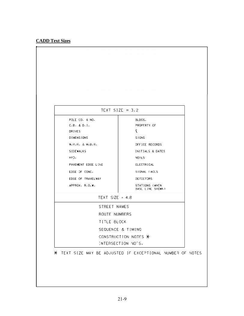
21-9
CADD Text Sizes

21-10
Traffic Signal Faces

21-11
Movement Diagram

21-12
Energy Block

21-13
Metric Dimensional Guide

21-14
Commonly Used Construction Notes
Figure 21-1 Commonly Used Construction Notes

22-1
22 GLOSSARY* Actuated Type of control which responds to vehicle or pedestrian
detection. Amplifier A device used in a vehicle detection system that produces a
signal when a vehicle passes through or remains within the detection zone of a sensing element.
Artery An arterial or main street generally considered the
thoroughfare with preferential right-of-way. Background Cycle Term used in coordinated systems to identify the cycle
lengths established by coordination unit and master control; takes precedence over intersection control cycle length.
Bandwidth The amount of green time available to a platoon of vehicles to
travel without stopping through all intersections in a progressive signal system. Also referred to as through band.
Barrier Reference point in the sequence of a dual ring controller unit
(CU) at which all rings are interlocked. Barriers assure that conflicting phases in different rings will not time concurrently. In a dual quad sequence the barriers are after phases 2 & 6 and after phases 4 & 8. Rings cross the barrier simultaneously.
Beginning of Green The theoretical beginning of artery green of a signal in a
coordinated system when all phases max out. Call A registration of a demand for right-of-way by traffic
(vehicular or pedestrian) to a controller. Centralized System A computer control system in which the master computer,
central communication facilities, console, keyboard and display equipment are all situated at a single location. From this center, the operating staff coordinates and controls traffic signals and related traffic control functions throughout the area.
Controller Assembly A group of electrical devices, including the controller unit,
conflict monitor, vehicle detectors, and other auxiliary equipment housed in an enclosure that together provide the operation of a traffic signal.
*NOTE: Pre-Emption Definitions and Pre-Emption Settings Definitions are included in Chapter 9.
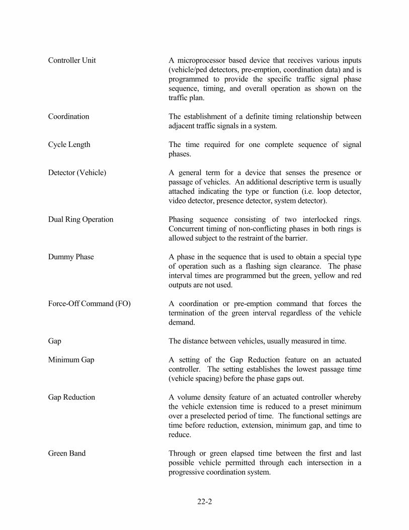
22-2
Controller Unit A microprocessor based device that receives various inputs (vehicle/ped detectors, pre-emption, coordination data) and is programmed to provide the specific traffic signal phase sequence, timing, and overall operation as shown on the traffic plan.
Coordination The establishment of a definite timing relationship between
adjacent traffic signals in a system. Cycle Length The time required for one complete sequence of signal
phases. Detector (Vehicle) A general term for a device that senses the presence or
passage of vehicles. An additional descriptive term is usually attached indicating the type or function (i.e. loop detector, video detector, presence detector, system detector).
Dual Ring Operation Phasing sequence consisting of two interlocked rings.
Concurrent timing of non-conflicting phases in both rings is allowed subject to the restraint of the barrier.
Dummy Phase A phase in the sequence that is used to obtain a special type
of operation such as a flashing sign clearance. The phase interval times are programmed but the green, yellow and red outputs are not used.
Force-Off Command (FO) A coordination or pre-emption command that forces the
termination of the green interval regardless of the vehicle demand.
Gap The distance between vehicles, usually measured in time. Minimum Gap A setting of the Gap Reduction feature on an actuated
controller. The setting establishes the lowest passage time (vehicle spacing) before the phase gaps out.
Gap Reduction A volume density feature of an actuated controller whereby
the vehicle extension time is reduced to a preset minimum over a preselected period of time. The functional settings are time before reduction, extension, minimum gap, and time to reduce.
Green Band Through or green elapsed time between the first and last
possible vehicle permitted through each intersection in a progressive coordination system.

22-3
Interval Any one of the several divisions of the time cycle during which signal indications do not change.
Loop Detector Also known as Inductive Loop Detector (ILD). A device
capable of sensing a change in inductance of a loop of wire imbedded in the roadway caused by the passage or presence of a vehicle over the loop.
Manual Pattern A set of controller cycles, splits, and offsets for a traffic
control network (or sub-network) which determines the relative green light sequencing of the intersections within the network (or sub-network) and which can only be selected through an operator command.
Mode (Detector) A detector setting that selects how the detector outputs the
call to the controller unit (i.e. presence, pulse, delay). Mode (Phase) A phase setting that selects how a phase operates in the
sequence (i.e. lock, non-lock, minimum recall, maximum recall, pedestrian recall).
Offset The time difference from the reference line of the system to
the beginning of the artery yellow interval at each intersection.
Operations Center Consists of the room(s) that contains the computer
equipment, displays and controls and houses the personnel which operate this equipment used in a computerized traffic control system.
Parent Phase A phase with which the operation of a subordinate phase,
dummy phase, or a pre-emption movement is dependent. Permissive Period An extension of the yield period in which the controller will
yield (transfer) to another phase. Phase The part of the total time cycle allotted to any traffic
movement receiving the right-of-way. Thus, the main street green, yellow and red intervals make up the main street phase.
Recall A phase mode in an actuated controller which will cause the
automatic return of the right-of-way to a street without vehicle or pedestrian demand. Usually applied to a non-actuated movement.

22-4
Reference Line A line perpendicular to the time axis on a time space diagram. It should normally be drawn through the beginning of the artery yellow at the master location.
Ring Two or more conflicting phases arranged to occur in an
established order. Single Ring Operation (Sequential) Phasing sequence consisting of one ring. One phase must
terminate before another becomes active. Special Event Plan A timing plan (a set of cycles, splits and offsets) stored in
memory which is activated to compensate for unusual traffic flow caused by a special event (such as a football game).
Split The segment of the system cycle length allocated to each
phase that may occur (expressed in percent and seconds). All splits add up to 100 percent or the cycle length.
Standby Mode An operational status of a local controller assembly or system
which is not under central computer control but is capable of responding to central computer control.
System Two or more traffic signals operating in coordination. System Detector Any type of detector that is used for traffic information such
as speed, volume, and occupancy. Time-Base Coordination Type of coordination which uses an electronic clock, rather
than an interconnect cable. Time Before Reduction (TBR) A setting of the Gap Reduction feature of an actuated
controller. The setting delays the start of gap reduction. Time to Reduce (TTR) A setting of the Gap Reduction feature of an actuated
controller. The setting establishes the rate of reduction. Time-of-Day Plan A timing plan (set of cycles, splits, and offsets) for a section
which is automatically implemented at certain time(s) in the day by a pre-set schedule.
Timing Plan A set of timing patterns (cycles, splits and offsets) within a
section of signals. The particular timing for each intersection may vary with time of day within the plan.
Traffic Responsive Plan A timing plan (set of cycles, splits, and offsets) for a section
which is implemented in response to the real time demands of traffic as sensed by the vehicle detectors.

22-5
Variable Initial A volume density feature of an actuated controller whereby
the minimum green interval can be increased to accommodate the number of vehicles which have passed over the approach detectors when the phase is in yellow or red. The functional settings are minimum green, added initial (seconds per actuation), and max initial.
Vehicle Headway The distance between the fronts of two successive vehicles
measured in time. Volume Density A controller operation that will automatically adjust the
timing of a phase by using variable initial and/or gap reduction. For detailed description refer to NEMA TS2 Standards.
Yield Period The part of the signal cycle during which the coordinated
phase is allowed to terminate its green interval. Usually 3% of the cycle length.
Yield Point The point where the coordinated phase yields to another
phase (beginning of artery yellow).

23-1
23 SIGNAL MANUAL UPDATE SHEET If you would like to receive updates to this manual please complete the form below and return it to: Mr. David M. Fabry Transportation Supervising Engineer Division of Traffic Engineering Connecticut Department of Transportation P. O. Box 317546 Newington, Connecticut 06131-7546 Attention: Signal Manual Updates FAX (860) 594-3376 E-MAIL [email protected] _______________________________________________________________________________ COMPANY ________________________________________ NAME ATTENTION: ________________________________________ ADDRESS: ________________________________________ ________________________________________ ________________________________________ PHONE (_____)__________________________________ FAX (_____)__________________________________ E-MAIL ________________________________________