TRADE THEORY
109
(i) NATIONAL INSTRUCTIONAL MEDIA INSTITUTE, CHENNAI SECTOR: Electrical TRADE THEORY Post Box No. 3142, CTI Campus, Guindy, Chennai - 600 032 ELECTRICIAN DIRECTORATE GENERAL OF TRAINING MINISTRY OF SKILL DEVELOPMENT & ENTREPRENEURSHIP GOVERNMENT OF INDIA NSQF LEVEL - 5 1 st Year (Volume I of II) Copyright Free under CC BY Licence
Transcript of TRADE THEORY

(i)
NATIONAL INSTRUCTIONALMEDIA INSTITUTE, CHENNAI
SECTOR: Electrical
TRADE THEORY
Post Box No. 3142, CTI Campus, Guindy, Chennai - 600 032
ELECTRICIAN
DIRECTORATE GENERAL OF TRAININGMINISTRY OF SKILL DEVELOPMENT & ENTREPRENEURSHIP
GOVERNMENT OF INDIA
NSQF LEVEL - 5
1st Year (Volume I of II)
Copyright Free under CC BY Licence

(ii)
Sector : ElectricalDuration : 2 - YearsTrade : Electrician 1St Year (Volume I of II) - Trade Theory - NSQF (LEVEL - 5)
First Edition : August 2018 Copies : 1,000Second Edition : November 2018 Copies : 10,000
Rs.285/-
All rights reserved.
No part of this publication can be reproduced or transmitted in any form or by any means, electronic or mechanical, includingphotocopy, recording or any information storage and retrieval system, without permission in writing from the NationalInstructional Media Institute, Chennai.
Published by:
NATIONAL INSTRUCTIONAL MEDIA INSTITUTEP. B. No.3142, CTI Campus, Guindy Industrial Estate,
Guindy, Chennai - 600 032.Phone : 044 - 2250 0248, 2250 0657, 2250 2421
Fax : 91 - 44 - 2250 0791email : [email protected]
[email protected]: www.nimi.gov.in
Copyright Free under CC BY Licence

(iii)
FOREWORD
The Government of India has set an ambitious target of imparting skills to 30 crores people, one out of every four Indians, by 2020 to help them secure jobs as part of the National Skills Development Policy. Industrial Training Institutes (ITIs) play a vital role in this process especially in terms of providing skilled manpower. Keeping this in mind, and for providing the current industry relevant skill training to Trainees, ITI syllabus has been recently updated with the help of Mentor Councils comprising of various stakeholder's viz. Industries, Entrepreneurs, Academicians and representatives from ITIs.
National Instructional Media Institute (NIMI), Chennai has come up with instructional material to suit the revised curriculum for Electrician 1st Year (Volume I of II) Trade Theory NSQF Level - 5 in Electrical sector under Semester Pattern required for ITIs and related institutions imparting skill development. The NSQF Level 5 will help the trainees to get an international equivalency standard where their skill proficiency and competency will be duly recognized across the globe and this will also increase the scope of recognition of prior learning. NSQF level 5 trainees will also get the opportunities to promote life long learning and skill development. I have no doubt that with NSQF level 5 the trainers and trainees of ITIs, and all stakeholders will derive maximum benefits from these IMPs and that NIMI's effort will go a long way in improving the quality of Vocational training in the country.
The Executive Director & Staff of NIMI and members of Media Development Committee deserve appreciation for their contribution in bringing out this publication.
Jai Hind
RAJESH AGGARWALDirector General / Addl. Secretary,
Ministry of Skill Development & Entrepreneurship,Government of India.
New Delhi - 110 001
Copyright Free under CC BY Licence

(iv)
PREFACE
The National Instructional Media Institute (NIMI) was established in 1986 at Chennai by then DirectorateGeneral of Employment and Training (D.G.E & T), Ministry of Labour and Employment, (now under DirectorateGeneral of Training, Ministry of Skill Development and Entrepreneurship) Government of India, with technicalassistance from the Govt. of the Federal Republic of Germany. The prime objective of this institute is todevelop and provide instructional materials for various trades as per the prescribed syllabi NSQF (Level 5)under the Craftsman and Apprenticeship Training Schemes.
The instructional materials are created keeping in mind, the main objective of Vocational Training underNCVT/NAC in India, which is to help an individual to master skills to do a job. The instructional materials aregenerated in the form of Instructional Media Packages (IMPs). An IMP consists of Theory book, Practicalbook, Test and Assignment book, Instructor Guide, Audio Visual Aid (Wall charts and Transparencies) andother support materials.
The trade theory book provides related theoretical knowledge required to enable the trainee to do a job. Thetest and assignments will enable the instructor to give assignments for the evaluation of the performance ofa trainee. The wall charts and transparencies are unique, as they not only help the instructor to effectivelypresent a topic but also help him to assess the trainee's understanding. The instructor guide enables theinstructor to plan his schedule of instruction, plan the raw material requirements, day to day lessons anddemonstrations.
IMPs also deals with the complex skills required to be developed for effective team work. Necessary carehas also been taken to include important skill areas of allied trades as prescribed in the syllabus.
The availability of a complete Instructional Media Package (IMF) in an institute helps both the trainer andmanagement to impart effective training.
The IMPs are the outcome of collective efforts of the staff members of NIMI and the members of the MediaDevelopment Committees specially drawn from Public and Private sector industries, various training institutesunder the Directorate General of Training (DGT), Government and Private ITIs.
NIMI would like to take this opportunity to convey sincere thanks to the Directors of Employment & Trainingof various State Governments, Training Departments of Industries both in the Public and Private sectors,Officers of DGT and DGT field institutes, proof readers, individual media developers and coordinators, but forwhose active support NIMI would not have been able to bring out this materials.
R. P. DHINGRAChennai - 600 032 EXECUTIVE DIRECTOR
Copyright Free under CC BY Licence

(v)
ACKNOWLEDGEMENT
National Instructional Media Institute (NIMI) sincerely acknowledges with thanks for the co-operation and
contribution extended by the following Media Developers and their sponsoring organisations to bring out this
instructional material (Trade Theory) for the trade of Electrician NSQF (LEVEL - 5) under Electrical Sector for
ITIs.
MEDIA DEVELOPMENT COMMITTEE MEMBERS
Shri. T. Muthu − Principal (Retd.),MDC Member.NIMI, Chennai
Shri. C.C. Jose − Training Officer (Retd.),MDC Member,NIMI, Chennai
Shri. K. Lakshmanan − Assistant Training Officer (Retd.),MDC Member,NIMI, Chennai.
NIMI CO-ORDINATORS
Shri. K. Srinivasa Rao − Joint DirectorNIMI, Chennai - 32.
Shri. V. Gopalakrishnan − Assitant Manager,NIMI, Chennai - 32
NIMI records its appreciation for the Data Entry, CAD, DTP operators for their excellent and devoted services inthe process of development of this Instructional Material.
NIMI also acknowledges with thanks the invaluable efforts rendered by all other NIMI staff who have contributedtowards the development of this Instructional Material.
NIMI is also grateful to everyone who has directly or indirectly helped in developing this Instructional Material.
Copyright Free under CC BY Licence

(vi)
INTRODUCTION
This manual for trade Theory is intended for use in the ITI classoom. It consists of a series of practical exercisesthat are to be completed by the trainees during the first semester of course is the Electrician trade underElectrical Sector. It is National Skills Qualifications Framework (NSQF) - (LEVEL 5), supplemented andsupported by instructions/information to assist the trainees in performing the exercises. The syllabus for the1st
Semester Electrician NSQF (LEVEL - 5) Trade under Electrical Sector Trade Practical is divided intoSix Modules.The allocation of time for the various modules is given below:
Module 1: Safety Practice and Hand Tools 14 Exercises 75 Hrs
Module 2: Basic Workshop Practice (Allied Trade) 09 Exercises 100 Hrs
Module 3: Wires, Joints - Soldering - U.G. Cables 10 Exercises 125 Hrs
Module 4: Basic Electrical Practice 11 Exercises 75 Hrs
Module 5: Magnetism and Capacitors 08 Exercises 50 Hrs
Module 6: AC Circuits 12 Exercises 100 Hrs
Total 64 Exercises 525 Hrs
The syllabus and the content in the modules are interlinked. As the number of workstations available in the electricalsection is limited by the machinery and equipment, it is necessary to interpolate the exercises in the modules toform a proper teaching and learning sequence. The sequence of instruction is given in the schedule of instructionwhich is incorporated in the Instructor's Guide. With 25 practical hours a week of 5 working days 100 hours ofpractical per month is available.
The procedure for working through the 64 exercises for the 1st semester with the specific objectives to be achievedas the learning out comes at the end of each exercise is given in this book.
The symbols used in the diagrams comply with the Bureau of Indian Standards (BIS) specifications.
This manual on trade Theory forms part of the Written Instructional Material (WIM). Which includes manual on tradetheory and assignment/test.
Copyright Free under CC BY Licence
(vii)
CONTENTS
Lesson No. Title of the Lesson Page No.
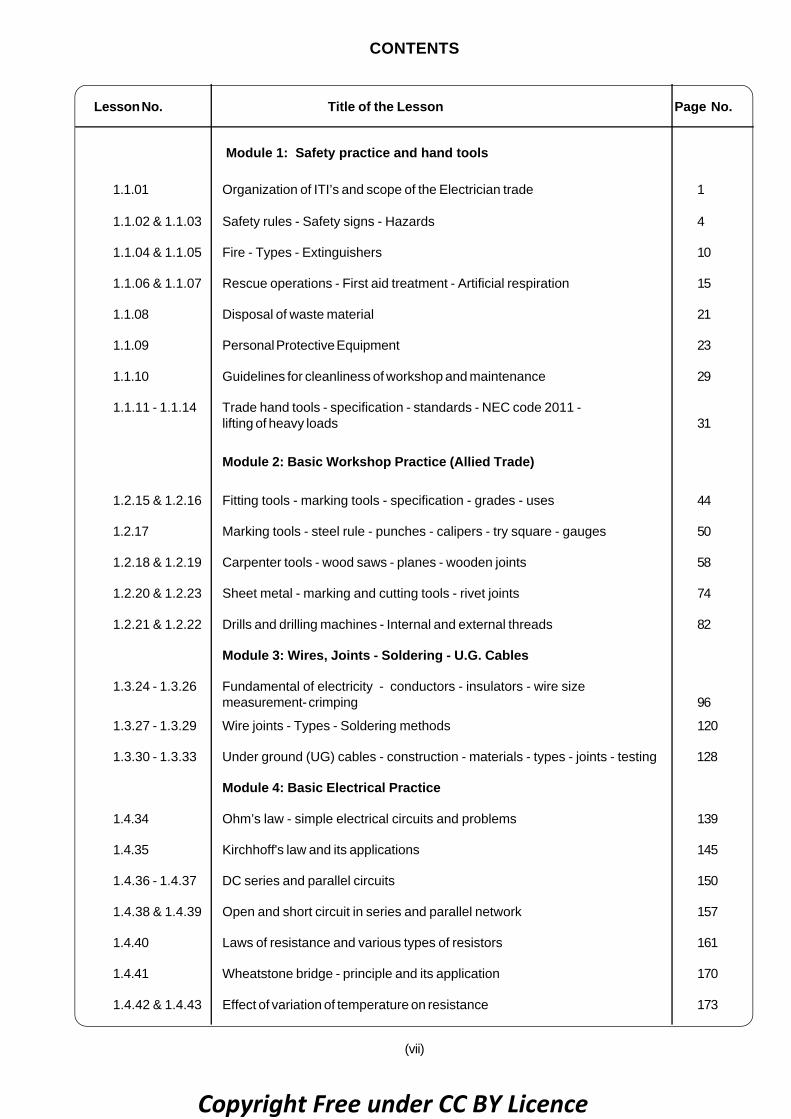
Module 1: Safety practice and hand tools
1.1.01 Organization of ITI’s and scope of the Electrician trade 1
1.1.02 & 1.1.03 Safety rules - Safety signs - Hazards 4
1.1.04 & 1.1.05 Fire - Types - Extinguishers 10
1.1.06 & 1.1.07 Rescue operations - First aid treatment - Artificial respiration 15
1.1.08 Disposal of waste material 21
1.1.09 Personal Protective Equipment 23
1.1.10 Guidelines for cleanliness of workshop and maintenance 29
1.1.11 - 1.1.14 Trade hand tools - specification - standards - NEC code 2011 -lifting of heavy loads 31
Module 2: Basic Workshop Practice (Allied Trade)
1.2.15 & 1.2.16 Fitting tools - marking tools - specification - grades - uses 44
1.2.17 Marking tools - steel rule - punches - calipers - try square - gauges 50
1.2.18 & 1.2.19 Carpenter tools - wood saws - planes - wooden joints 58
1.2.20 & 1.2.23 Sheet metal - marking and cutting tools - rivet joints 74
1.2.21 & 1.2.22 Drills and drilling machines - Internal and external threads 82
Module 3: Wires, Joints - Soldering - U.G. Cables
1.3.24 - 1.3.26 Fundamental of electricity - conductors - insulators - wire sizemeasurement- crimping 96
1.3.27 - 1.3.29 Wire joints - Types - Soldering methods 120
1.3.30 - 1.3.33 Under ground (UG) cables - construction - materials - types - joints - testing 128
Module 4: Basic Electrical Practice
1.4.34 Ohm’s law - simple electrical circuits and problems 139
1.4.35 Kirchhoff's law and its applications 145
1.4.36 - 1.4.37 DC series and parallel circuits 150
1.4.38 & 1.4.39 Open and short circuit in series and parallel network 157
1.4.40 Laws of resistance and various types of resistors 161
1.4.41 Wheatstone bridge - principle and its application 170
1.4.42 & 1.4.43 Effect of variation of temperature on resistance 173
Copyright Free under CC BY Licence

(viii)
Lesson No. Title of the Lesson Page No.
1.4.44 Series and parallel combination circuit 175
Module 5: Magnetism and Capacitors
1.5.45 Magnetic terms, magnetic material and properties of magnet 178
1.5.46 & 1.5.47 Principles and laws of electro magnetism 183
1.5.48 -1.5.50 The magnetic circuits - self and mutually induced emfs 186
1.5.51 & 1.5.52 Capacitors - types - functions , grouping and uses 196
Module 6: AC Circuits6: AC Circuits
1.6.53 Alternating current - terms & definitions - vector diagrams 211
1.6.54 Series resonance circuit 236
1.6.55 R-L, R-C and R-L-C parallel circuits 239
1.6.56 Parallel resonance circuits 246
1.6.57 Power, energy and power factor in AC single phase system - Problems 249
1.6.58 & 1.6.59 Power factor - Improvement of power factor 259
1.6.60 - 1.6.64 3-Phase AC fundamentals 263
Project Work 276
Copyright Free under CC BY Licence

(ix)
ASSESSABLE / LEARNING OUTCOME
On completion of this book you shall be able to
• Apply safe working practices
• Prepare profile with an appropriate accuracy as per drawing
• Prepare electrical wire joints, carry out soldering, crimping andmeasure insulation resistance of underground cable.
• Verify characteristics of electrical and magnetic circuits.
Copyright Free under CC BY Licence
WeekNo.
Ref. LearningOutcome
Professional Skills(Trade Practical)with Indicative hours
Professional Knowledge(Trade Theory)
• Apply safe workingpractices
1.
• Install and setupoperating systemand related softwarein a computer.
2.• Install and setup
operating systemand related softwarein a computer.
3
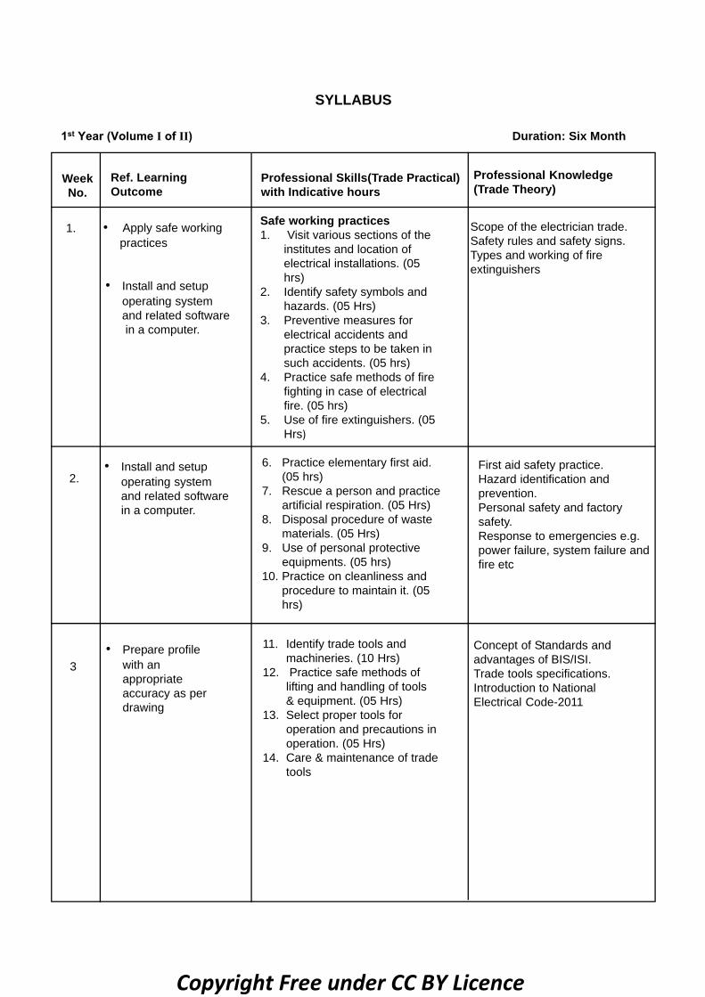
6. Practice elementary first aid.(05 hrs)
7. Rescue a person and practiceartificial respiration. (05 Hrs)
8. Disposal procedure of wastematerials. (05 Hrs)
9. Use of personal protectiveequipments. (05 hrs)
10. Practice on cleanliness andprocedure to maintain it. (05hrs)
First aid safety practice.Hazard identification andprevention.Personal safety and factorysafety.Response to emergencies e.g.power failure, system failure andfire etc
• Prepare profilewith anappropriateaccuracy as perdrawing
11. Identify trade tools andmachineries. (10 Hrs)
12. Practice safe methods oflifting and handling of tools& equipment. (05 Hrs)
13. Select proper tools foroperation and precautions inoperation. (05 Hrs)
14. Care & maintenance of tradetools
Concept of Standards andadvantages of BIS/ISI.Trade tools specifications.Introduction to NationalElectrical Code-2011
Safe working practices1. Visit various sections of the
institutes and location ofelectrical installations. (05hrs)
2. Identify safety symbols andhazards. (05 Hrs)
3. Preventive measures forelectrical accidents andpractice steps to be taken insuch accidents. (05 hrs)
4. Practice safe methods of firefighting in case of electricalfire. (05 hrs)
5. Use of fire extinguishers. (05Hrs)
Scope of the electrician trade.Safety rules and safety signs.Types and working of fireextinguishers
SYLLABUS
htnoM xiS :noitaruD 1st Year (Volume I of II)
Copyright Free under CC BY Licence

6 - 7
8
4 - 5• Prepare profile
with anappropriateaccuracy asperdrawing
15. Operations of allied tradetools. (05 Hrs)
16. Workshop practice on filingand hacksawing. (10 Hrs)
17. Prepare hand coil windingassembly. ( 5 Hrs)
18. Practice on preparing T-joint,straight joint and dovetailjoint on wooden blocks. (15Hrs)
19. Practice sawing, planing,drilling and assembling formaking a woodenswitchboard. (15 Hrs)
Allied trades: Introduction tofitting tools, safety precautions.Description of files, hammers,chisels hacksaw frames, blades,their specification and grades.Marking tools description anduse.Types of drills, description &drilling machines.Various wooden joints
• Prepareprofilewith anappropriateaccuracy asperdrawing
20. Practice in marking andcutting of straight andcurved pieces in metalsheets, making holes,securing by screw andriveting. (10 Hrs)
21. Workshop practice ondrilling, chipping, internaland external threading ofdifferent sizes. (20 Hrs)
22. Practice of making squareholes in crank handle. (5Hrs)
23. Prepare an open box frommetal sheet. (15 Hrs)
Marking tools; calipersDividers, Surface plates,Angle plates, Scribers, punches,surface gauges Types, Uses, Careand maintenance.Sheet metal tools: Description ofmarking & cutting tools.Types of rivets and riveted joints.Use of thread gauge.Description of carpenter’s toolsCare and maintenance of tools
• Prepareelectrical wirejoints, carryoutsoldering,crimping andmeasureinsulationresistance ofundergroundcable
24. Prepare terminations ofcable ends (02 hrs)
25. Practice on skinning, twistingand crimping. (15 Hrs)
26. Identify various types ofcables and measureconductor size using SWGand micrometer. (8 Hrs)
Fundamentals of electricity,definitions, units & effects ofelectric current.Conductors and insulators.Conducting materials and theircomparison
• Prepareelectricalwirejoints,carry outsoldering,crimpingandmeasureinsulationresistanceofundergroundcable
27. Make simple twist,married,Tee and western unionjoints. (18 Hrs)
28. Make britannia straight,britannia Tee and rattailjoints. (18 Hrs)
29. Practice in Soldering ofjoints/ lugs. (14 Hrs)
Joints in electrical conductors.Techniques of soldering.Types of solders and flux
9 - 10
Copyright Free under CC BY Licence

13 - 14
15
11 - 12
• Prepareelectrical wirejoints, carry outsoldering,crimping andmeasureinsulationresistance ofundergroundcable
30. Identify various parts,skinning and dressing ofunderground cable. (15Hrs)
31. Make straight joint ofdifferent types ofunderground cable. (15Hrs)
32. Test insulation resistance ofunderground cable usingmegger. (05 hrs)
33. Test underground cablesforfaults and remove the fault.(15 Hrs)
Underground cables: Description,types, various joints and testingprocedure.Cable insulation & voltage gradesPrecautions in using varioustypes of cables
• Verifycharacteristicsofelectrical andmagneticcircuits
34. Practice on measurement ofparameters in combinationalelectrical circuit by applyingOhm’s Law for differentresistor values and voltagesources and analyse bydrawing graphs. (15 Hrs)
35. Measure current and voltagein electrical circuits to verifyKirchhoff’s Law (10 Hrs)
36. Verify laws of series andparallel circuits with voltagesource in differentcombinations. (05Hrs)
37. Measure voltage and currentagainst individual resistancein electrical circuit (10 hrs)
38. Measure current and voltageand analyse the effects ofshorts and opens in seriescircuit. (05 Hrs)
39. Measure current and voltageand analyse the effects ofshorts and opens in parallelcircuit. (05 Hrs)
Ohm’s Law; Simple electricalcircuits and problems.Kirchoff’s Laws andapplications.Series and parallel circuits.Open and short circuits inseriesand parallel networks
• Verifycharacteristicsof electrical andmagneticcircuits
40. Measure resistance usingvoltage drop method. (5Hrs)
41. Measure resistance usingwheatstone bridge. (5Hrs)
42. Determine the thermaleffect of electric current.(5Hrs)
43. Determine the change inresistance due totemperature. (5 Hrs)
44. Verify the characteristicsofseries parallelcombinationof resistors. (5 Hrs)
Laws of Resistanceand varioustypes ofresistorsWheatstonebridge; principle andits applications.Effect of variation oftemperatureon resistance.Different methods ofmeasuringthe values ofresistance.Series and parallelcombinationsof resistors
Copyright Free under CC BY Licence

16 - 17
18 - 19
• Verifycharacteristics ofelectrical andmagneticcircuits
45. Determine the poles andplot the field of a magnetbar. (08 Hrs)
46. Wind a solenoid anddetermine the magneticeffect of electric current. (06Hrs)
47. Measure induced emf due tochange in magnetic field. (06hrs)
48. Determine direction ofinduced emf and current. (06hrs)
49. Practice on generation ofmutually induced emf. (08hrs)
50. Measure the resistance,impedance and determineinductance of choke coils indifferent combinations. (06Hrs)
51. Identify various types ofcapacitors, charging /discharging and testing. (05Hrs)
52. Group the given capacitorsto get the required capacityand voltage rating. (05 Hrs)
Magnetic terms, magneticmaterials and properties ofmagnet.Principles and laws ofelectromagnetism.Self and mutually induced EMFs.Electrostatics: Capacitor-Different types, functions,grouping and uses.Inductive and capacitivereactance, their effect on ACcircuit and related vectorconcepts
• Verifycharacteristics ofelectrical andmagneticcircuits
53. Measure current, voltageand PF and determine thecharacteristics of RL, RC andRLC in AC series circuits. (08Hrs)
54. Measure the resonancefrequency in AC series circuitand determine its effect onthe circuit. (07 hrs)
55. Measure current, voltageand PF and determine thecharacteristics of RL, RC andRLC in AC parallel circuits.(08 Hrs)
56. Measure the resonancefrequency in AC parallelcircuit and determine itseffects on the circuit. (07hrs)
57. Measure power, energy forlagging and leading powerfactors in single phasecircuits and comparecharacteristic graphically.(08 Hrs)
58. Measure Current, voltage,power, energy and powerfactor in three phase circuits.(07 hrs)
59. Practice improvement of PFby use of capacitor in threephase circuit.(05 Hrs)
Comparison and Advantages ofDC and AC systems.Related terms frequency,Instantaneous value, R.M.S.valueAverage value, Peak factor, formfactor, power factor andImpedance etc.Sine wave, phase and phasedifference.Active and Reactive power.Single Phase and three-phasesystem.Problems on A.C. circuits
Copyright Free under CC BY Licence

• Verifycharacteristicsofelectrical andmagneticcircuits
60. Ascertain use of neutral byidentifying wires of a 3-phase 4 wire system and findthe phase sequence usingphase sequence meter. (10Hrs)
61. Determine effect of brokenneutral wire in three phasefour wire system.(05 hrs)
62. Determine the relationshipbetween Line and Phasevalues for star and deltaconnections. (10Hrs)
63. Measure the Power of threephase circuit for balancedand unbalanced loads. (15Hrs)
64. Measure current and voltageof two phases in case of onephase is short-circuited inthree phase four wire systemand compare with healthysystem.(10 hrs)
Advantages of AC poly-phasesystem.Concept of three-phase Star andDelta connection.Line and phase voltage, currentand power in a 3 phase circuitswith balanced and unbalancedload.Phase sequence meter
Project work / Industrial visitBroad Areas:
a) Prepare and assemble a test board with switches, plug socket, lamp holderetc.
b) Temperature controlled system for switching ‘ON’ and ‘OFF’ of any circuitusing bimetallicstrip.
c) Series/ parallel combinational circuits
Revision
Examination
20 - 21
22 - 23
24 - 25
26
Copyright Free under CC BY Licence

1
Electrical Related Theory for Exercise 1.1.01Electrician - Safety Practice and Hand Tools
Organization of ITI’s and scope of the electrician tradeObjectives: At the end of this lesson you shall be able to• state brief introduction about Industrial Training Institutes (ITI)• state about the organized structure of the Institute.
Brief Introduction of Industrial Training Institute (ITIs)
Industrial Training Institute plays a vital role in economy ofthe country, especially interms of providing skilledmanpower.
The Directorate General of Training (DGT) comes underMinistry of Skill Development and Entrepreneurship(MSDE) offers a range of vocational training trades indifferent sectors based on economy /labour market. Thevocational training programs are delivered under the aegisof National Council of Vocational Training (NCVT).Craftsman Training scheme (CTS) and ApprenticeshipTraining Scheme (ATS) and two pioneer programs of NCVTfor Propagatory Vocational Training.
Total number of ITIs in India as on April 2016 is about13105 (Govt. 2293 + 10812 Private ITIs). They are givingtraining about 132 trades including Engineering and Non-
engineering with the duration of 1 or 2 years. The minimumeligibility for admission in ITIs 8th, 10th and 12th passwith respect to the trades and admission process will beheld in every year in July.
From 2013, semester pattern was introduced with 6months/Semester and revised the syllabus for eachsemester. Then in 2014, they introduced and implemented"Sector Mentor council (SMC)" re-revised syllabus under11 sectors of about 80 trades.
At the end of each semester, All India Trade Test (AITT)will be conducted in every July and January, with OMRanswer sheet pattern and multiple choice type questions.After passing, National trade certificates (NTC), will beissued by DGT which is authorized and recognizedinternationally. In 2017, for some trades they haveintroduced and implemented National Skill QualificationFrame work (NSQF) with Level 4 and Level 5.
Copyright Free under CC BY Licence

2 Electrical : Electrician (NSQF LEVEL - 5) - Related Theory for Exercise 1.1.01
After finishing instructional training with 'NTC' certificate,they have to undergo Apprenticeship training (ATS) for oneor two year in respective trades under the Apprentice ACT1961, in various government and private establishmentswith stipend. At the end of the Apprenticeship training, AllIndia Apprentice Test will be conducted and apprenticecertificate will be issued. They can get job opportunities inprivate or government establishment in India/Abroad or theycan start small scale industries in manufacturing or inservice sector with subsidiary government loan.
Scope of the electrician tradeObjectives: At the end of this lesson you shall be able to• explain the duties of electrician general and electrical fitter and their NCO• state the key skills and carrier pathway for electrician• list out the job opportunities and self employment opportunities.
Organizational Structure of ITIsIn most of the ITIs, the head of the institute is the principalunder him one vice-principal (VP). then Training Officers(TO)/Group Instructors (GI) who are the management andsupervisory staff. Then Assistant Training Officers(ATO),Junior Training Officer (JTO), and Vocational Instructors(VI) are under Training officers for each trade and forWorkshop calculations, Engineering Drawing,Employability skills etc. Administrative staff, HostelSuperintendent (H.S.) physical Education Trainer (PET),Library incharge, Pharmacist, etc. will be under the headof the Institution.
The typical organizational of ITI chart is shown in Fig 1
Welcome to the electrician tradeElectrician trade under craftsman training scheme (CTS)is one of the most popular trade delivered nationwidethrough the network of ITIs. This trade is of two year (4semester) duration.
It mainly consists of domain area and core areas. In domainarea trade practical and trade theory and core areaworkshop calculation and science, Engineering drawingand employability skills which imparts soft and life skills.There are two professional classification in electrician tradebased on National Code of Occupation (NCO) as
(i) Electrician general (NCO - 2015 reference is 7411.0100)
(ii) Electrical fitter (NCO - 2015 reference is 7412.0200)
Duties of Electrician - General and Electrical - FitterElectrician - General installs, maintains and repairselectrical machinery, equipment and fittings in factories,workshops, power houses, business and residentialpremises, etc. Studies drawings and other specificationsto determine electrical circuit, installation etc. Positionsand installs electrical motors, transformers, switchboards,microphones, loud-speakers and other electricalequipment, fittings and lighting fixtures. Makes connectionsand solder terminals. Tests electrical installations andequipment and locates faults using megger, test lamp etc.
Repairs or replaces defective wiring , burnt out fuses anddefective parts and keeps fittings and fixtures in workingorder. may do armature winding, draw wires and cablesand do simple cable joining. May operate, attend andmaintain electrical motors, pumps etc. NCO - 2015reference is 7411.0100
Record class of work in which experienced such as factory,power-house, ship etc., whether experienced in electricalrepairs or detecting faults, details of experience in electrical
equipment such as sound recording apparatus, airpurification plant, heating apparatus etc. whether used toworking do drawing, whether accustomed to high tensionor low tension supply system and if in possession ofcompetency certificate issued under electricity act.
Electrical fitter fits and assembles electrical machineryand equipment such as motors, transformers, generators,switch gears, fans, etc., Studies drawings and wiringdiagrams of fittings, wiring and assemblies to be made.Collects prefabricated electrical and mechanicalcomponents according to drawing and wiring diagram andchecks them with gauges, megger etc. to ensure properfunction and accuracy.
Fits mechanical components, resistance, insulators, etc.as per specification doing supplementary tooling wherenecessary. Follows wiring diagrams, makes electricalconnections and solder points as specified. Checks forcontinuity, resistance, circuit shorting, leakage, earthingetc., at each stage of assembly using megger, ammeter,voltmeter and other appliances and ensures stipulatedperformance of both mechanical and electrical componentsfilled in assembly.
Erects various equipment such as bus bars, panel board,electrical post, fuse boxes switch gears, meters, relaysetc., using non-conductors, insulating and hoistingequipment as necessary for receipt and distribution ofelectrical current to feeder lines.
Installs motors, generators, transformers, etc. as perdrawing using lifting and hoisting equipment as necessary,does prescribed electrical wirings and connects to supplyline. Locates faults in case of breakdown and replacesblown out fuses, burnt coils, switches, conductors, etc.as required. Checks dismantles, repairs and overhaulselectrical units periodically or as required according toscheduled procedure.
Copyright Free under CC BY Licence

3Electrical : Electrician (NSQF LEVEL - 5) - Related Theory for Exercise 1.1.01
Test electrical equipment and rewind blown out coils. Mayspecialize in repairs of particular type of electricalappliances and machinery, equipment manufacturing,installation or power house work and be designatedaccordingly NCO - 2015 reference is 7412.0200
Record nature of work done; if specialized in repairing orassembling any particular item such as generator, motor,transformer, relays switchgear, domestic appliance etc. ,experience of working in power-house and distributioncentre and if in possession of electrician's competencycertificate
Key Skills of ElectricianAfter passing the electrician trade, they are able to
• Read and interpret technical parameter documents, planand organic work process, identify necessary materialsand tools
• Perform tasks with due consideration to safety rules,accident prevention regulation and environmentprotection.
• Apply professional skill knowledge and employabilityskills while performing jobs.
• Checking job/assembly as per drawing for functioning,identifying and rectifying errors in job/assembly.
• Document the technical parameters related to the tasksundertaken
• In 2013, semester systems was introduced and thesyllabus also revised for semester pattern
• Then in 2014 Sector Mentor Council (SMC) was formedand the syllabus was also re-revised and implemented.
Presently electrician syllabus again revised andsequentially structured by National Skill QualificationFramework NSQF - level 5 and implemented from August2017
Carrier Progress PathwaysAfter passing the electrician trade the trainee can appearin 10+2 examination through National Institute of OpenSchooling (NIOS) for acquiring higher secondary certificateand can go further for general Technical education.
• Take admission in diploma course in notified branchesof engineering by lateral entry
• Can join the apprenticeship training in different types
of industries and obtain National ApprenticeshipCertificate (NAC)
• Can join Craftsman Instructor Training Scheme (CITS)in the trade to become instructor in ITIs
• Eligible to obtain directly wireman 'B' license, which isissued by the Electrical Licensing Board Authorities
Job Opportunities: There are good numbers of jobopportunities for an electrician
• Electrician in local electricity boards, railways,Telephone department, airport and other governmentand semi-government establishments
• Electrician in factories (Public/Private) Install, test andmaintain electrical equipment in auditorium and cinemahalls
• Assembler of electrical control gears and switches onpanel boards at switch gear factories.
• Winder of electrical motors in winding shops
• Electrical appliances repairer in electrical shops.
• Electrician to Install, service and maintain electricalequipment and circuits in hotels, resorts hospitals andflats
• Assembler in the domestic appliances manufacturingfactories
• Service technician for domestic appliances in reputedcompanies.
Self-employment opportunities• Service centre for repairing electrical switch gear and
motors in rural and urban areas.
• Maintenance contractor of wiring installation in hotels/resorts/hospitals/banks etc.
• Manufacturer of sub-assembly for electrical panels
• Contractor for domestic wiring and industrial wiring
• Armature winder of electrical motors
• Repairer of simple electronic of gadgets.
• Service, maintain and repair of domestic appliances
• Dealership/agency for electrical hardware
• With an added training in the specified field can becomeAudio/Radio/ TV Mechanic
Copyright Free under CC BY Licence

4
Electrical Related Theory for Exercise 1.1.02 & 1.1.03Electrician - Safety Practice and Hand Tools
Safety rules - Safety signs - HazardsObjectives: At the end of this lesson you shall be able to• explain the necessity of adopting the safety rules• list the safety rules to be followed by the electrician.• explain how to treat a person for electric shock/injury
Necessity of safety rules: Safety consciousness is oneof the essential attitudes required for any job. A skilledelectrician always should strive to form safe workinghabits. Safe working habits always save men, money andmaterial. Unsafeworking habits always end up in loss ofproduction and profits, personal injury and even death. Thesafety hints given below should be followed by Electricianto avoid accidents and electrical shocks as his job involvesa lot of occupational hazards.
The listed safety rules should be learnt, remembered andpractised by every electrician. Here a electrician shouldremember the famous proverb, “Electricity is a goodservant but a bad master”.Safety rules• Only qualified persons should do electrical work.
• Keep the workshop floor clean, and tools in goodcondition, and keep proper places.
• Do not work on live circuits; if unavoidable, use rubbergloves rubber mats, etc.
• Use wooden or PVC insulated handle screwdriverswhen working on electrical circuits.
• Do not touch bare conductors
• When soldering, place the hot soldering irons in theirstand. Never lay switched ‘ON’ or heated soldering ironon a bench or table as it may cause a fire to break out.
• Use only correct capacity fuses in the circuit. If thecapacity is less it will blow out when the load isconnected. If the capacity is large, it gives no protectionand allows excess current to flow and endangers menand machines, resulting in loss of money.
• Replace or remove fuses only after switching off thecircuit switches.
• Use extension cords with lamp guards to protect lampsagainst breakage and to avoid combustible materialcoming in contact with hot bulbs.
• Use accessories like sockets, plugs, switches andappliances only when they are in good condition and besure they have the mark of BIS (ISI). Necessity of usingBIS(ISI) marked accessories is explained understandardisation.
• Never extend electrical circuits by using temporarywiring.
• Stand on a wooden stool, or an insulated ladder whilerepairing live electrical circuits/ appliances or replacing
fused bulbs. In all the cases, it is always good to openthe main switch and make the circuit dead.
• Stand on rubber mats while working/operating switchpanels, control gears etc.
• Position the ladder, on firm ground.
• While using a ladder, ask the helper to hold the ladderagainst any possible slipping.
• Always use safety belts while working on poles or highrise points.
• Never place your hands on any moving part of rotatingmachine and never work around moving shafts orpulleys of motor or generator with loose shirt sleeves ordangling neck ties.
• Only after identifying the procedure of operation, operateany machine or apparatus.
• Run cables or cords through wooden partitions or floorafter inserting insulating porcelain tubes.
• Connections in the electrical apparatus should be tight.Loosely connected cables will heat up and end in firehazards.
• Use always earth connection for all electrical appliancesalong with 3-pin sockets and plugs.
• While working on dead circuits remove the fuse grips;keep them under safe custody and also display ‘Men online’ board on the switchboard.
• Do not meddle with interlocks of machines/switchgears.
• Do not connect earthing to the water pipe lines.
• Do not use water on electrical equipment.
• Discharge static voltage in HV lines/equipment andcapacitors before working on them.
Safety practice - first aidElectric shockWe are aware that the prime reasons for severity of shockare the magnitude of current and duration of contact. Inaddition, the other factors contribute to the severity of shockare:
• age of person
• body resistance
• not wearing insulating footwear or wearing wet footwear
Copyright Free under CC BY Licence

5
• Weather condition
• Wet or dry floor
• Mains voltage etc.
If assistance is close at hand, send for medical aid, thencarry on with emergency treatment.
If you are alone, proceed with the treatment immediately.
Make sure the victim is not in contact with the supply.
Effects of electric shockThe effect of current at very low levels may only be anunpleasant tingling sensation, but this itself may besufficient to cause some persons to lose their balanceand fall.
At higher levels of current the person receiving a shockmay be thrown off his feet and will experience severe painand possibly minor burns at the point of contact.
At an excessive shock can also cause burning of the skinat the point of contact.
Treatment of electric shock
Prompt treatment is essential.
Check for the victim’s natural breathing and consciousness.Take steps to apply respiratory resuscitation if the victimis unconscious and not breathing.
Check the victim for injury and burns. Decide on the suitablemethod of artificial resuscitation.
In the case of injury/burns to chest and or belly, follow themouth-to-mouth method.
In the case of burns/injury in the back, follow Nelson’smethod
In case the mouth is closed tightly, use Schafer’s orHolgen-Nelson method.
These methods should be practiced. (Refer Exercise1.1.06)
Treatment for electrical burnsA person receiving an electric shock may also sustainburns when the current passes through the body.
Do not waste time by rendering first aid to thevictim until breathing has been restored andthe patient can breathe normally unaided.
Burns are very painful. If a large area of the body is burnt,do not give treatment, except to exclude the air, eg. bycovering with clean paper or a clean cloth, soaked in cleanwater. this relieves the pain.
Severe bleedingAny wound which is bleeding profusely, especially in thewrist, hand or fingers must be considered serious andmust receive professional attention. As an immediate first
aid measure, pressure on the wound itself is the best meansof stopping the bleeding and avoiding infection.
Immediate actionAlways in cases of severe bleeding
- make the patient to lie down and rest
- if possible, raise the injured part above the level of thebody (Fig 1)
- apply pressure to the wound
- call for medical assistance
To control severe bleeding
Squeeze together the sides of the wound. Apply pressureas long as it is necessary to stop the bleeding. When thebleeding has stopped, put a dressing over the wound andcover it with a pad of soft material. (Fig 2)
For an abdominal wound which may be caused by fallingon a sharp tool, keep the patient bending over the woundto stop internal bleeding.
Large woundApply a clean pad and bandage firmly in place. If bleedingis very severe apply more than one dressing. (Fig 3)
Electrical : Electrician (NSQF LEVEL - 5) - Related Theory for Exercise 1.1.02 & 1.1.03
Copyright Free under CC BY Licence

6
• Single and short broken lines in the middle of the roadallow the vehicle to cross the dotted lines safelyovertake whenever required.
• When moving vehicle approaching pedestrian crossing,be ready to slow down or stop to let people cross.
• Do not overtake in the vicinity of pedestrian crossing.
Police signals (Fig 5)
To stop a vehicle approaching from behind. (Fig 5/1)
To stop a vehicle coming from front. (Fig 5/2)
To stop vehicles approaching simultaneously from frontand behind. (Fig 5/3)
To stop traffic approaching from left and wanting to turnright. (Fig 5/4)
To stop traffic approaching from the right to allow trafficfrom left to turn right. (Fig 5/5)
To allow traffic coming from the right and turning right bystopping traffic approaching from the left. (Fig 5/6)
Warning signal closing all traffic. (Fig 5/7)
Safety signs (Road signals)Objectives: At the end of this lesson you shall be able to• list three kinds of road sign• describe the “marking” on the road• describe the various police traffic hand signal and light signal• list the causes for collision.In olden days road locomotive carrying a red flag by dayand red lantern by night. Safety is the prime motive ofevery traffic.Kinds of road signs• Mandatory• Cautionary and• InformatoryMandatory signs (Fig 1)
Violation of mandatory sign can lead to penalties.Eg. Stop, give way, limits, prohibited, no parking andcompulsory sign.
Cautionary signs (Fig 2)
Cautionary/ warning signs are especially safe. Do's anddon'ts for pedestrians, cyclists, bus passengers andmotorists.
Information signs (Fig 3)
Information signs as especially benefit to the passengersand two wheelers.
Marking lines on road (Fig 4)
• Marking lines are directing or warning to the movingvehicles, cyclist and pedestrians to follow the law.
Electrical : Electrician (NSQF LEVEL - 5) - Related Theory for Exercise 1.1.02 & 1.1.03
Copyright Free under CC BY Licence

7
Beckoning on vehicles approaching from left. (Fig 5/8)
Beckoning on vehicles approaching from right. (Fig 5/9)
Beckoning on vehicles from front. (Fig 5/10)
Traffic light signals (Fig 6)
Green means you may go on if the way is clear. Takespecial care if you mean to turn left or right and give wayto pedestrians who are crossing. (Fig 6/3)
Amber means stop at the stop line. you may only go on ifthe amber appears after you have crossed the stop line orso close to it that to pull up may not be possible. (Fig 6/4)
Green arrow means that you may go in the direction shownby the arrow. You may do this whatever other lights maybe showing. (Fig 6/5)
Pedestrians - do not cross. (Fig 6/6)
Pedestrians - cross now. (Fig 6/7)
Flashing red means stop at the stop line and if the way isclear proceed with caution. (Fig 6/8)
Flashing amber means proceed with caution. (Fig 6/9)
Collision causes (Fig 7)
Three factors are responsible for collision
• Roads
• Vehicles and
• Drivers
The Fig 8 shows approximately proportionate causes ofcollision. In wrong attitudes such that avoid foolish acts atthe wheel (Fig 8). Driving time is not play time.
Electrical : Electrician (NSQF LEVEL - 5) - Related Theory for Exercise 1.1.02 & 1.1.03
Red means stop. Wait behind the stop line on the carriageway. (Fig 6/1)
Red and amber also means stop. Do not pass through orstart until green shows. (Fig 6/2)
Copyright Free under CC BY Licence

8
Safety practice - Safety signsObjectives: At the end of this lesson you shall be able to• state the responsibilities of employer and employees• state the safety attitude and list the four basic categories of safety signs.
ResponsibilitiesSafety doesn't just happen - it has to be organised andachieved like the work-process of which it forms a part.The law states that both an employer and his employeeshave a responsibility in this behalf.
Employer's responsibilitiesThe effort a firm puts into planning and organising work,training people, engaging skilled and competent workers,maintaining plant and equipment, and checking, inspectingand keeping records - all of this contributes to the safetyin the workplace.
The employer will be responsible for the equipmentprovided, the working conditions, what the employees areasked to do, and the training given.
Employee's responsibilitiesYou will be responsible for the way you use the equipment,how you do your job, the use you make of your training,and your general attitude to safety.
A great deal is done by employers and other people tomake your working life safer; but always remember youare responsible for your own actions and the effect theyhave on others. You must not take that responsibility lightly.
Rules and procedure at workWhat you must do, by law, is often included in the variousrules and procedures laid down by your employer. Theymay be written down, but more often than not, are just theway a firm does things - you will learn these from otherworkers as you do your job.
They may govern the issue and use of tools, protectiveclothing and equipment, reporting procedures, emergencydrills, access to restricted areas, and many other matters.Such rules are essential; they contribute to the efficiencyand safety of the job.
Safety signsAs you go about your work on a construction site you willsee a variety of signs and notices. Some of these will befamiliar to you - a 'no smoking' sign for example; othersyou may not have seen before. It is up to you to learn whatthey mean - and to take notice of them. They warn of thepossible danger, and must not be ignored.
Safety signs fall into four separate categories. These canbe recognised by their shape and colour. Sometimes theymay be just a symbol; other signs may include letters orfigures and provide extra information such as the clearanceheight of an obstacle or the safe working load of a crane.
The four basic categories of signs are as follows:
• prohibition signs (Fig 1 & Fig 5)
• mandatory signs (Fig 2 & Fig 6)
• warning signs (Fig 3 & Fig 7)
• information signs (Fig 4)
Prohibition signs
Electrical : Electrician (NSQF LEVEL - 5) - Related Theory for Exercise 1.1.02 & 1.1.03
Mandatory signsSHAPE Circular.
COLOUR White symbolon bluebackground
MEANING Shows whatmust be done.
Example Wear handprotection.
Fig 1
SHAPE Circular.
COLOUR Red borderand cross bar.Black symbolon whitebackground.
MEANING Shows it mustnot be done.
Example No smoking.
Fig 2
Warning signsSHAPE Triangular.
COLOUR Yellowbackgroundwith blackborder andsymbol.
MEANING Warns ofhazard ordanger.
Example Caution, risk ofelectric shock.
Fig 3
Copyright Free under CC BY Licence

9Electrical : Electrician (NSQF LEVEL - 5) - Related Theory for Exercise 1.1.02 & 1.1.03
Information signs
SHAPE Square oroblong.
COLOUR White symbolson greenbackground.
MEANING Indicates orgivesinformation ofsafetyprovision.
Example First aid point.
Prohibition signs
Fig 4
Mandatory signs
Warning signs
Copyright Free under CC BY Licence

10
Electrical Related Theory for Exercise 1.1.04 & 1.1.05Electrician - Safety Practice and Hand Tools
Fire - Types - ExtinguishersObjectives: At the end of this lesson you shall be able to• state the effects of a fire break out and causes of fire in a workshop• distinguish the different types of fire extinguishers• state the classification of fires and basic ways for extingushing the fire• determine the correct type of fire extinguisher to be used based on the class of fire• describe the general procedure to be adopted in the event of fire• state the method of operation of fire extinguisher and extinguishing of fire.FireFire is the burning of combustible material. A fire in anunwanted place and on an unwanted occasion and in anuncontrollable quantity can cause damage or destroyproperty and materials. It might injure people, andsometimes cause loss of life as well. Hence, every effortmust be made to prevent fire. When a fire outbreak isdiscovered, it must be controlled and extinguished byimmediate corrective action.
Is it possible to prevent fire? Yes, fire can be prevented byeliminating anyone of the three factors that causes fire.
The following are the three factors that must be present incombination for a fire to continue to burn. (Fig 1)
Removing any one of these factors willextinguish the fire.
Preventing fires: The majority of fires begin with smalloutbreaks which burn unnoticed until they have a securehold. Most fires could be prevented with more care and byfollowing some simple common sense rules.
Accumulation of combustible refuse (cotton waste soakedwith oil, scrap wood, paper, etc.) in odd corners are a firerisk. Refuse should be removed to collection points.
The cause of fire in electrical equipment is misuse orneglect. Loose connections, wrongly rated fuses, overloadedcircuits cause overheating which may in turn lead to a fire.Damage to insulation between conductors in cables causesfire.
Clothing and anything else which might catch fire should bekept well away from heaters. Make sure that the heater isshut off at the end of the working day.
Highly flammable liquids and petroleum mixtures (thinner,adhesive solutions, solvents, kerosene, spirit, LPG gasetc.) should be stored in the flammable material storagearea.
Blowlamps and torches must not be left burning when theyare not in use.
Classification of fires: Fires are classified into four typesin terms of the nature of fuel.
Different types of fires (Fig 2, Fig 3 Fig 4 & Fig 5) have tobe dealt with in different ways and with different extinguishingagents.
An extinguishing agent is the material or substance usedto put out the fire, and is usually (but not always) containedin a fire extinguisher with a release mechanism for sprayinginto the fire.
It is important to know the right type of agent for extinguishinga particular type of fire; using a wrong agent can makethings worse.There is no classification for ‘electrical fires’as such, since these are only fires in materials whereelectricity is present.
Fuel: Any substance, liquid, solid or gas will burn, if thereis oxygen and high enough temperatures.
Heat: Every fuel will begin to burn at a certain temperature.It varies and depends on the fuel. Solids and liquids give offvapour when heated, and it is this vapour which ignites.Some liquids do not have to be heated as they give offvapour at normal room temperature say 150C, eg. petrol.
Oxygen: Usually exists in sufficient quantity in air to keepa fire burning.
Extinguishing of fire: Isolating or removing any of thesefactors from the combination will extinguish the fire. Thereare three basic ways of achieving this.
• Starving the fire of fuel removes this element.
• Smothering - ie. isolate the fire from the supply ofoxygen by blanketing it with foam, sand etc.
• Cooling - use water to lower the temperature.
Copyright Free under CC BY Licence

11
Fire Classification and Fuel Extinguishing Method
Most effective ie., cooling with water. Jets of watershould be sprayed on the base of the fire and thengradually upwards.
Should be smothered :- The aim is to cover theentire surface of the burning liquid. This has theeffect of cutting off the supply of oxygen to the fire.
Water should never be used on burning liquids.
Foam, dry powder or CO2 may be used on this typeof fire.
Extreme caution is necessary in dealing with liquefiedgases. There is a risk of explosion and suddenoutbreak of fire in the entire vicinity. If an appliancefed from a cylinder catches fire - shut off the supplyof gas. The safest course is to raise an alarm andleave the fire to be dealt with by trained personnel.
Dry powder extinguishers are used on this type offire.
Special powders have now been developed whichare capable of controlling and/or extinguishing thistype of fire.
The standard range of fire extinguishing agents isinadequate or dangerous when dealing with metalfires.
Fire on electrical equipment.
Halon, Carbon dioxide, dry powder and vapourisingliquid (CTC) extinguishers can be used to deal withfires in electrical equipment. Foam or liquid (eg.water) extinguishers must not be used on electricalequipment under any circumstances.
Electrical : Electrician (NSQF LEVEL - 5) - Related Theory for Exercise 1.1.04 & 1.1.05
Copyright Free under CC BY Licence

12
Types of Fire ExtinguisherMany types of fire extinguishers are available with differentextinguishing ‘agents’ to deal with different classes of fires.(Fig 1)
Water-filled extinguishers: There are two methods ofoperation. (Fig 2)• Gas cartridge type• Stored pressure typeWith both methods of operation the discharge can beinterruted as required, conserving the contents andpreventing unnecessary water damage.
Foam extinguishers (Fig 3):These may be of storedpressure or gas cartridge types. Always check the operatinginstructions on the extinguisher before use.Most suitable for• flammable liquid fires• running liquid firesMust not be used on fires where electrical equipment isinvolved.
Dry powder extinguishers (Fig 4): Extinguishers fittedwith dry powder may be of the gas cartridge or storedpressure type. Appearance and method of operation is thesame as that of the water-filled one. The main distinguish-ing feature is the fork shaped nozzle. Powders have beendeveloped to deal with class D fires.
Carbon dioxide (CO2): This type is easily distinguishedby the distinctively shaped discharge horn. (Fig 5).
Suitable for Class B fires. Best suited where contaminationby deposits must be avoided. Not generally effective inopen air.Always check the operating instructions on the containerbefore use. Available with different gadgets of operationsuch as - plunger, lever, trigger etc.Halon extinguishers (Fig 6): These extinguishers may befilled with carbon-tetrachloride and Bromochlorodifluoromethene (BCF). They may be either gas cartridge or storedpressure type.
Electrical : Electrician (NSQF LEVEL - 5) - Related Theory for Exercise 1.1.04 & 1.1.05
Copyright Free under CC BY Licence

13
Failure to do this may mean that some personbeing unaccounted for and others may have toput themselves to the trouble of searching forhim or her at risk to themselves.
Working on fire extinguishers:-• Alert people sorrounding by shouting fire, fire, fire when
observe the fire. (Fig 1a & b)
• Inform fire service or arrange to inform immediately.(Fig 1c)
• Open emergency exist and ask them to go away.(Fig 1d)
• Put “OFF” electrical power supply.
Don’t allow people to go nearer to the fire
Electrical : Electrician (NSQF LEVEL - 5) - Related Theory for Exercise 1.1.04 & 1.1.05
They are more effective in extinguishing small fires involvingpouring liquids. These extinguishers are particularly suitableand safe to use on electrical equipment as the chemicalsare electrically non-conductive.
The fumes given off by these extinguishers aredangerous, especially in confined space.
The general procedure in the event of a fire:• Raise an alarm.• Turn off all machinery and power (gas and electricity).• Close the doors and windows, but do not lock or bolt
them. This will limit the oxygen fed to the fire and preventits spreading.
• Try to deal with the fire if you can do so safely. Do notrisk getting trapped.
• Anybody not involved in fighting the fire should leavecalmly using the emergency exits and go to thedesignated assembly point.
Copyright Free under CC BY Licence
14
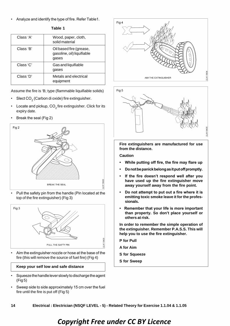
• Analyze and identify the type of fire. Refer Table1.
Table 1
Class ‘A’ Wood, paper, cloth,solid material
Class ‘B’ Oil based fire (grease,gasoline, oil) liquifiablegases
Class ‘C’ Gas and liquifiablegases
Class ‘D’ Metals and electricalequipment
Electrical : Electrician (NSQF LEVEL - 5) - Related Theory for Exercise 1.1.04 & 1.1.05
• Pull the safety pin from the handle (Pin located at thetop of the fire extinguisher) (Fig 3)
• Aim the extinguisher nozzle or hose at the base of thefire (this will remove the source of fuel fire) (Fig 4)
Keep your self low and safe distance
• Squeeze the handle lever slowly to discharge the agent(Fig 5)
• Sweep side to side approximately 15 cm over the fuelfire until the fire is put off (Fig 5)
Fire extinguishers are manufactured for usefrom the distance.Caution• While putting off fire, the fire may flare up• Do not be panick belong as it put off promptly.• If the fire doesn’t respond well after you
have used up the fire extinguisher moveaway yourself away from the fire point.
• Do not attempt to put out a fire where it isemitting toxic smoke leave it for the profes-sionals.
• Remember that your life is more importantthan property. So don’t place yourself orothers at risk.
In order to remember the simple operation ofthe extinguisher. Remember P.A.S.S. This willhelp you to use the fire extinguisher.P for PullA for AimS for SqueezeS for Sweep
Assume the fire is ‘B; type (flammable liquifiable solids)
• Slect CO2 (Carbon di oxide) fire extinguisher.
• Locate and pickup, CO2 fire extinguisher. Click for itsexpiry date.
• Break the seal (Fig 2)
Copyright Free under CC BY Licence
15
Electrical Related Theory for Exercise 1.1.06 & 1.1.07Electrician - Safety Practice and Hand Tools
Rescue operation - First aid treatment - Artificial respirationObjectives: At the end of this lesson you shall be able to• explain how to rescue a person who is in contact with a live wire.• state the first aid and its key aims.• explain ABC of the first aid.• brief how to give first aid treatment for a victim.• explain how to treat a person affected due to electric shock/injury.
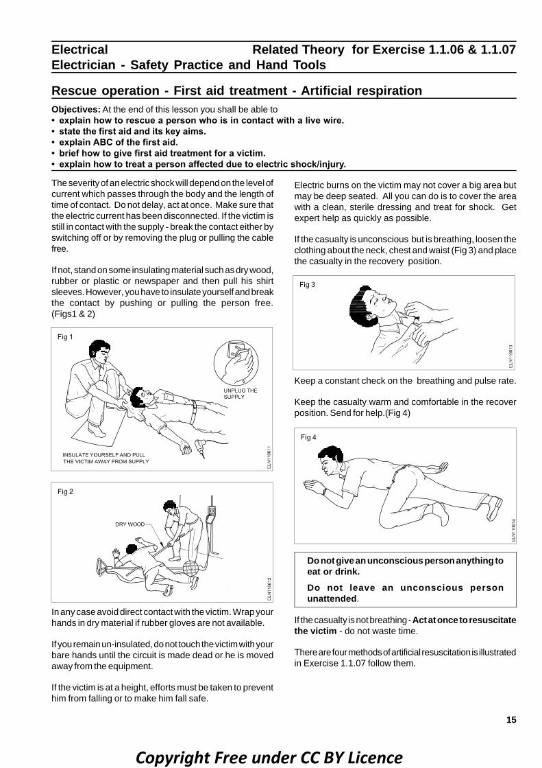
The severity of an electric shock will depend on the level ofcurrent which passes through the body and the length oftime of contact. Do not delay, act at once. Make sure thatthe electric current has been disconnected. If the victim isstill in contact with the supply - break the contact either byswitching off or by removing the plug or pulling the cablefree.
If not, stand on some insulating material such as dry wood,rubber or plastic or newspaper and then pull his shirtsleeves. However, you have to insulate yourself and breakthe contact by pushing or pulling the person free.(Figs1 & 2)
In any case avoid direct contact with the victim. Wrap yourhands in dry material if rubber gloves are not available.
If you remain un-insulated, do not touch the victim with yourbare hands until the circuit is made dead or he is movedaway from the equipment.
If the victim is at a height, efforts must be taken to preventhim from falling or to make him fall safe.
Electric burns on the victim may not cover a big area butmay be deep seated. All you can do is to cover the areawith a clean, sterile dressing and treat for shock. Getexpert help as quickly as possible.
If the casualty is unconscious but is breathing, loosen theclothing about the neck, chest and waist (Fig 3) and placethe casualty in the recovery position.
Keep a constant check on the breathing and pulse rate.
Keep the casualty warm and comfortable in the recoverposition. Send for help.(Fig 4)
Do not give an unconscious person anything toeat or drink.Do not leave an unconscious personunattended.
If the casualty is not breathing - Act at once to resuscitatethe victim - do not waste time.
There are four methods of artificial resuscitation is illustratedin Exercise 1.1.07 follow them.
Copyright Free under CC BY Licence

16
Basic first-aid treatmentFirst aid is defined as the immediate care and supportgiven to an acutely injured or ill person, primarily to savelife, prevent further deterioration or injury, plan to shift thevictim to safer place, provide best possible comfort andfinally help them to reach the medical centre/ hospitalthrough all available means. It is an immediate life-savingprocedure using all resources available within reach.
Imparting knowledge and skill through institutional teachingat younger age group in schools, colleges, entry point atindustry level is now given much importance. Inculcatingsuch habits at early age, helps to build good healthcarehabits among people.
be invasive, and carry a risk of further injury to the patientand the provider. As with any training, it is more useful if itoccurs before an actual emergency, and in many countries,emergency ambulance dispatchers may give basic firstaid instructions over the phone while the ambulance is onthe way.
Training is generally provided by attending a course,typically leading to certification. Due to regular changesin procedures and protocols, based on updated clinicalknowledge, and to maintain skill, attendance at regularrefresher courses or re-certification is often necessary.First aid training is often available through communityorganization such as the Red cross and St. Johnambulance.
ABC of first aidABC stands for Airway, Breathing and Circulation.
• Airway: Attention must first be brought to the airwayto ensure it is clear. Obstruction (choking) is a life-threatening emergency.
• Breathing: Breathing if stops, the victim may die soon.Hence means of providing support for breathing is animportant next steps. There are several methodspracticed in first aid.
• Circulation: Blood circulation is vital to keep personalive. The first aiders now trained to go straight to chestcompressions through CPR methods.
When providing first aid one needs to follow some rule.There are certain basic norms in teaching and trainingstudents in the approach and administration of first aid tosick and injured.
Not to get panicPanic is one emotion that can make the situation moreworse. People often make mistake because they get panic.Panic clouds thinking may cause mistakes. First aiderneed calm and collective approach. If the first aider himselfis in a state of fear and panic gross mistakes may result.It's far easier to help the suffering,
When they know what they are doing, even if unpreparedto encounter a situation. Emotional approach and responsealways lead to wrong doing and may lead one to do wrongprocedures. Hence be calm and focus on the giveninstitution. Quick and confident approach can lessen theeffect of injury.
Call medical emergenciesIf the situation demands, quickly call for medicalassistance. Prompt approach may save the life.
Surroundings play vital roleDifferent surroundings require different approach. Hencefirst aider should study the surrounding carefully. In otherwords, one need to make sure that they are safe and arenot in any danger as it would be of no help that the firstaider himself get injured.
First aid procedure often consists of simple and basic lifesaving techniques that an individual performs with propertraining and knowledge.
The key aims of first aid can be summarized in three keypoints:
• Preserve life: If the patient was breathing, a first aiderwould normally then place them in the recovery position,with the patient leant over on their side, which also hasthe effect of clearing the tongue from the pharynx. Italso avoids a common cause of death in unconsciouspatients, which is choking on regurgitated stomachcontents.
The airway can also become blocked through a foreignobject becoming lodged in the pharynx or larynx,commonly called choking. The first aider will be taughtto deal with this through a combination of 'back slaps'and 'abdominal thrusts'. Once the airway has beenopened, the first aider would assess to see if the patientis breathing.
• Prevent further harm: Also sometimes called preventthe condition from worsening, or danger of further injury,this covers both external factors, such as moving apatient away from any cause of harm, and applyingfirst aid techniques to prevent worsening of the condition,such as applying pressure to stop a bleed becomingdangerous.
• Promote recovery: First aid also involves trying tostart the recovery process from the illness or injury,and in some cases might involve completing atreatment, such as in the case of applying a plaster toa small wound.
TrainingBasic principles, such as knowing to use an adhesivebandage or applying direct pressure on a bleed, are oftenacquired passively through life experiences. However, toprovide effective, life-saving first aid interventions requiresinstruction and practical training.
This is especially true where it relates to potentially fatalillnesses and injuries, such as those that require CardioPulmonary Resuscitation (CPR); these procedures may
Electrical : Electrician (NSQF LEVEL - 5) - Related Theory for Exercise 1.1.06 & 1.1.07
Copyright Free under CC BY Licence

17
Do no harmMost often over enthusiastically practiced first aid viz.administering water when the victim is unconscious, wipingclotted blood (which acts as plug to reduce bleeding),correcting fractures, mishandling injured parts etc., wouldleads to more complication.
Patients often die due to wrong FIRST AID methods, whomay otherwise easily survive. Do not move the injuredperson unless the situation demands. It is best to makehim lie wherever he is because if the patient has back,head or neck injury, moving him would causes more harm.
ReassuranceReassure the victim by speaking encouragingly with him.
Stop the bleedingIf the victim is bleeding, try to stop the bleeding by applyingpressure over the injured part.
Golden hoursIndia have best of technology made available in hospitalsto treat devastating medical problem viz. head injury,multiple trauma, heart attack, strokes etc, but patientsoften do poorly because they don't gain access to thattechnology in time.
The risk of dying from these conditions, is greatest in thefirst 30 minutes, often instantly. This period is referred toas Golden period. By the time the patient reach thehospital, they would have passed that critical period. Firstaid care come handy to save lives.
It helps to get to the nearest emergency room as quicklyas possible through safe handling and transportation. Theshorter that time, the more likely the best treatmentapplied.
Maintain the hygieneMost important, the first aider need to wash hands anddry before giving any first aid treatment to the patient orwear gloves in order to prevent infection.
Cleaning and dressingAlways clean the wound thoroughly before applying thebandage gently wash the wound with clean water.
Not to use local medications on cuts or open woundsThey are more irritating to tissue than it is helpful. Simpledry cleaning or with water and some kind of bandage arebest.
CPR (Cardio-Pulmonary Resuscitation) can be life-sustainingCPR can be life sustaining. If one is trained in PR and theperson is suffering from choking or finds difficulty inbreathing, immediately begin CPR. However, if one is nottrained in CPR, do not attempt as you can cause furtherinjury. But some people do it wrong.
This is a difficult procedure to do in a crowded area. Alsothere are many studies to suggest that no survivaladvantage when bystanders deliver breaths to victims
compared to when they only do chest compressions.Second, it is very difficult to carry right maneuver in wrongplaces. But CPR, if carefully done by highly skilled firstaiders is a bridge that keeps vital organs oxygenated untilmedical team arrives.
Declaring deathIt is not correct to declare the victim's death at the accidentsite. It has to be done by qualified medical doctors.
How to report an emergency?Reporting an emergency is one of those things that seemssimple enough, until actually when put to use in emergencysituations. A sense of shock prevail at the accident sites.Large crowd gather around only with inquisitive nature,but not to extend helping hands to the victims. This iscommon in road side injuries.
The first aiders need to adapt multi-task strategy to controlthe crowd around, communicate to the rescue team, callambulance etc., all to be done simultaneously. The mobilephones helps to a greater extent for such emergencies.
Assess the urgency of the situation. Before you report anemergency, make sure the situation is genuinely urgent.Call for emergency services if you believe that a situationis life-threatening or otherwise extremely critical.
• A crime, especially one that is currently in progress. Ifyou're reporting a crime, give a physical description ofthe person committing the crime.
• A fire - If you're reporting a fire, describe how the firestarted and where exactly it is located. If someonehas already been injured or is missing, report that aswell.
• A life-threatening medical emergency, explain how theincident occurred and what symptoms the personcurrently displays.
• A car crash - Location, serious nature of injures, vehicle'sdetails and registration, number of people involved etc.
Call emergency serviceThe emergency number varies - 100 for Police & Fire, 108for Ambulance.
Report your locationThe first thing the emergency dispatcher will ask is whereyou are located, so the emergency services can get thereas quickly as possible. Give the exact street address, ifyou're not sure of the exact address, give approximateinformation.
Give the dispatcher your phone numberThis information is also imperative for the dispatcher tohave, so that he or she is able to call back if necessary.
Describe the nature of the emergencySpeak in a calm, clear voice and tell the dispatcher whyyou are calling. Give the most important details first, thenanswer the dispatcher's follow-up question as best as youcan.
Electrical : Electrician (NSQF LEVEL - 5) - Related Theory for Exercise 1.1.06 & 1.1.07
Copyright Free under CC BY Licence
18
Do not hang up the phone until you are instructed to doso. Then follow the instructions you were given.
How to do basic first aid?Basic first aid refers to the initial process of assessingand addressing the needs of someone who has been injuredor is in physiological distress due to choking, a heartattack, allergic reactions, drugs or other medicalemergencies. Basic first aid allows one to quicklydetermine a person's physical condition and the correctcourse of treatment.
Important guideline for first aidersEvaluate the situationAre there things that might put the first aider at risk. Whenfaced with accidents like fire, toxic smoke, gasses, anunstable building, live electrical wires or other dangerousscenario, the first aider should be very careful not to rushinto a situation, which may prove to be fatal.
Remember A-B-CsThe ABCs of first aid refer to the three critical things thefirst aiders need to look for.
• Airway - Does the person have an unobstructed airway?
• Breathing - Is the person breathing?
• Circulation - Does the person show a pulse at majorpulse points (wrist, carotid artery, groin)
Avoid moving the victimAvoid moving the victim unless they are immediate danger.Moving a victim will often make injuries worse, especiallyin the case of spinal cord injuries.
Call emergency servicesCall for help or tell someone else to call for help as soonas possible. If alone at the accident scene, try to establishbreathing before calling for help, and do not leave the victimalone unattended.
Determine responsivenessIf a person is unconscious, try to rouse them by gentlyshaking and speaking to them.
If the person remains unresponsive, carefully rollthem on the side (recovery position) and open hisairway.• Keep head and neck aligned.
• Carefully roll them onto their back while holding hishead.
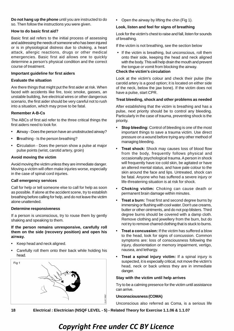
• Open the airway by lifting the chin (Fig 1).
Look, listen and feel for signs of breathingLook for the victim's chest to raise and fall, listen for soundsof breathing.
If the victim is not breathing, see the section below
• If the victim is breathing, but unconscious, roll themonto their side, keeping the head and neck alignedwith the body. This will help drain the mouth and preventthe tongue or vomit from blocking the airway.
Check the victim's circulationLook at the victim's colour and check their pulse (thecarotid artery is a good option; it is located on either sideof the neck, below the jaw bone). If the victim does nothave a pulse, start CPR.
Treat bleeding, shock and other problems as neededAfter establishing that the victim is breathing and has apulse, next priority should be to control any bleeding.Particularly in the case of trauma, preventing shock is thepriority.
• Stop bleeding: Control of bleeding is one of the mostimportant things to save a trauma victim. Use directpressure on a wound before trying any other method ofmanaging bleeding.
• Treat shock: Shock may causes loss of blood flowfrom the body, frequently follows physical andoccasionally psychological trauma. A person in shockwill frequently have ice cold skin, be agitated or havean altered mental status, and have pale colour to theskin around the face and lips. Untreated, shock canbe fatal. Anyone who has suffered a severe injury orlife-threatening situation is at risk for shock.
• Choking victim: Choking can cause death orpermanent brain damage within minutes.
• Treat a burn: Treat first and second degree burns byimmersing or flushing with cool water. Don't use creams,butter or other ointments, and do not pop blisters. Thirddegree burns should be covered with a damp cloth.Remove clothing and jewellery from the burn, but donot try to remove charred clothing that is stuck to burns.
• Treat a concussion: If the victim has suffered a blowto the head, look for signs of concussion. Commonsymptoms are: loss of consciousness following theinjury, disorientation or memory impairment, vertigo,nausea, and lethargy.
• Treat a spinal injury victim: If a spinal injury issuspected, it is especially critical, not move the victim'shead, neck or back unless they are in immediatedanger.
Stay with the victim until help arrivesTry to be a calming presence for the victim until assistancecan arrive.
Unconsciousness (COMA)Unconscious also referred as Coma, is a serious life
Electrical : Electrician (NSQF LEVEL - 5) - Related Theory for Exercise 1.1.06 & 1.1.07
Copyright Free under CC BY Licence

19
threatening condition, when a person lie totally senselessand do not respond to calls, external stimulus. But thebasic heart, breathing, blood circulation may be still intact,or they may also be failing. If unattended it may lead todeath.
The condition arises due to interruption of normal brainactivity. The causes are too many.
Causes for COMA Stage• Shock (Cardiogenic, Neurogenic)
• Head injury (Concussion, Compression)
• Asphyxia (obstruction to air passage)
• Extreme of body temperature (Heat, Cold)
• Cardiac arrest (Heart attack)
• Stroke (Cerbro-vascular accident)
• Blood loss (Haemorrhage)
• Dehydration (Diarrohea & vomiting)
• Diabetes (Low or high sugar)
• Blood pressure (Very low or very high)
• Over dose of alcohol, drugs
• Poisoning (Gas, Pesticides, Bites)
• Epileptic fits (Fits)
• Hysteria (Emotional, Psychological)
The following symptoms may occur after a person hasbeen unconscious:• Confusion• Drowsiness• Headache• Inability to speak or move parts of his or her body (see
stroke symptoms)• Light headedness• Loss of bowel or bladder control (incontinence)• Rapid heartbeat (palpitation)• Stupor
First aid• Call EMERGENCY number.
• Check the person's airway, breathing, and pulsefrequently. If necessary, begin rescue breathing andCPR.
• If the person is breathing and lying on the back andafter ruling out spinal injury, carefully roll the persononto the side, preferably left side.
Bend the top leg so both hip and knee are at rightangles. Gently tilt the head back to keep the airwayopen (Fig 2). If breathing or pulse stops at any time,roll the person on to his back and begin CPR.
• If there is a spinal injury, the victims position may haveto be carefully assessed. If the person vomits, roll the
entire body at one time to the side. Support the neckand back to keep the head and body in the sameposition while you roll.
• Keep the person warm until medical help arrives.
• If you see a person fainting, try to prevent a fall. Laythe person flat on the floor and raise the level of feetabove and support.
• If fainting is likely due to low blood sugar, give the personsomething sweet to eat or drink when they becomeconcious.
DO NOT• Do not give an unconscious person any food or drink.
• Do not leave the person alone.
• Do not place a pillow under the head of an unconsciousperson.
• Do not slap an unconscious person's face or splashwater on the face and try to revive him.
Loss of consciousness may threaten life if theperson is on his back and the tounge hasdropped to the back of the throat, blocking theairway. Make certain that the person isbreathing before looking for the cause ofunconsciousness. If the injuries permit, placethe casualty in the recovery position (Fig 2) withthe neck extended. Never give any thing bymouth to an unconscious casualty.
How to diagnose an unconscious injured person• Consider alcohol: look for signs of drinking, like empty
bottles or the smell of alcohol.
• Consider epilepsy: are there signs of a violent seizure,such as saliva around the mouth or a generallydishevelled scene?
• Think insulin: might the person be suffering from
Electrical : Electrician (NSQF LEVEL - 5) - Related Theory for Exercise 1.1.06 & 1.1.07
insulin shock.
• Think about drugs: was there an overdose? Or mightthe person have under dosed - that is not taken enoughof a prescribed medication?
• Consider trauma: is the person physically injured?
• Look for signs of infection: redness and/ or red streaksaround a wound.
• Look around for signs of Poison: an empty bottle of
Copyright Free under CC BY Licence

20
pills or a snakebite wound.
• Consider the possibility of psychological trauma:might the person have a psychological disorder of somesort?
• Consider stroke, particularly for elderly people.
• Treat according to what you diagnose.
Electric Shock (Fig 3)
A severe loss of body fluid will lead to a drop in bloodpressure. Eventually the blood's circulation will deteriorateand the remaining blood flow will be directed to the vitalorgans such as the brain. Blood will therefore be directedaway from the outer area of the body, so the victim willappear pale and the skin will feel ice cold.
As blood flow slows, so does the amount of oxygenreaching the brain. The victim may appear to be confused,weak, and dizzy and may eventually deteriorate intounconsciousness. Try to compensate for this lack ofoxygen, the heart and breathing rates both speed up,gradually becoming weaker, and may eventually cease.
Potential causes of shock include: sever internal or externalbleeding; burns; severe vomiting and diarrohea, especiallyin children and the elderly; problems with the heart.
Symptoms of shockVictims appear pale, ice cold, pulse appear initially fasterand gets slower, breathing becomes shallow. Weakness,dizziness, confusion continue. If unattended the patientmay become unconscious and die.
First aidKeep the patient warm and at mental rest. Assure of goodair circulation and comfort. Call for help to shift the patientto safer place/ hospital.
Electrical : Electrician (NSQF LEVEL - 5) - Related Theory for Exercise 1.1.06 & 1.1.07
• Warmth: Keep the victim warm but do not allow themto get overheated. If you are outside, try to getsomething underneath her if you can do easily. Wrapblankets and coats around her, paying particularattention to the head, through which much body heatis lost.
• Air: Maintain careful eye on the victim's airway and beprepared to turn them into the recovery position ifnecessary, or even to resuscitate if breathing stops.Try to keep back bystanders and loosen tight clothingto allow maximum air to victim.
• Rest: Keep the victim still and preferably sitting or lyingdown. If the victim is very giddy, lay them down withthere legs raised to ensure that maximum blood andtherefore maximum oxygen is sent to the brain.
Treatment of electric shockPrompt treatment is essential.
If assistance is close at hand, send for medical aid, thencarry on with emergency treatment.
If you are alone, proceed with treatment at once.
Switch off the supply, if this can be done without unduedelay. Otherwise, remove the victim from contact with thelive conductor, using dry non-conducting materials such asa wooden bar, rope, a scarf, the victim's coat-tails, any dryarticle of clothing, a belt, rolled-up newspaper, non-metallichose, PVC tubing, bakelised paper, tube etc. (Fig 4)
Avoid direct contact with the victim. Wrap your hands in drymaterial if rubber gloves are not available.
Electrical burns: A person receiving an electric shockmay also sustain burns when the current passes throughhis body. Do not waste time by applying first aid to theburns until breathing has been restored and the patient canbreathe normally - unaided.
Burns and scalds: Burns are very painful. If a large area ofthe body is burnt, give no treatment, except to exclude theair, eg.by covering with water, clean paper, or a clean shirt.This relieves the pain.
Artificial respiration methods to the electric shockvictimArtificical respiration methods already dealt in practicalexercise 1.1.07 in detail. Refer practical book.
Copyright Free under CC BY Licence

21
Electrical Related Theory for Exercise 1.1.08Electrician - Safety Practice and Hand Tools
Disposal of waste materialObjectives: At the end of this lesson you shall be able to• state about the waste material• state the types of waste material and source of waste• list out the waste material in workshop• explain the methods of disposal of waste material.
WasteWaste are unwanted or unusable materials. Waste is anysubstance which is discarded after primary use, or it isworthless, defective and of no use.
Waste is the by product of all the matter which is consumedby living organisms and is used in the industries as wellas in agriculture and other fields. Usually this waste isthrown on areas outside the cities but this open disposaldecreases the usable land into non-usable land and alsopolluting the environment.
Waste can be broadly classified as follows
a) Rural waste
b) Urban waste
i) Solid waste
II) Liquid waste
a) Rural wasteRural waste is the waste from agricultural and dairy forms.These can be reused by burning agricultural waste andcomposing. The waste produced by the man and animalis now used in the production of fuel by bio-gas plants.
b) Urban wasteIt is the waste from house hold articles or from industrieswithin municipal limit
It can be again classified into two types.
i) Solid wasteSolid waste is the material is hard (from industries) suchas newspaper, cans, bottles, broken glass, plasticscontainer, polythene bags etc.
ii) Liquid wasteIt is the water based waste which is produced by the mainactivation sources of waste.
Sources of wastei) Industrial wasteIt contains solid as well as liquid waste and is formed bythe processing of various materials and it contains harmfulchemical and solid metal waste.
ii) Domestic wasteIt includes all rubbish, garbage, dust, sewage waste etc.It contains combustible and non-combustible materials.When these waste disposal off openly cause variousharmful effects.
iii) Agricultural wasteIt includes the waste produced from the crops and cattleetc. Open disposal of thin waste create problems for healthof man and other animals.
iv) Flu ash produced by interval power plants.
v) Hospital waste is most harmful waste off containsmicro organisms which cause both communicable andnon-communicable deseases.
List out the waste material in workshop (Fig 1)
• Oily waste such as lubricating oil, coolant etc.
• Cotton waste.
• Metal chips of different materials.
• Electrical waste such as used and damagedaccessories, wires, cables, pipes etc.
Methods of disposal of waste (Fig 2)
Disposal process : This is the final step of the wastemanagement. From this disposal point or site the materialsare selected steps as
• Recycling
• Composing
Copyright Free under CC BY Licence

22
• Landfill
• Incineration
• Waste compaction
• Reuse
• Animal Feed
• Fire Wood
RecyclingRecycling is one of the most well known method ofmanaging waste. It is not expensive and can be easilydone by you. If you carry out recycling, you will save a lotof energy, resources and thereby reduce pollution.
CompostingThis is a natural process that is completely free of anyhazardous by-products. This process involves breakingdown the material into organic compounds that can beused as manure.
LandfillIn this process, the waste cannot be reused or recycledseparated out and spread as a thin layer in some low-lying areas across the city. A layer of soil added aftereach layer of garbage. Once this process is complete,this area declared unfit for building construction and isonly used as a playground or a park.
Incineration (Fig 3)
It is the process of controlled combustion of garbage toreduce it to incombustible matter, ash, waste gas andheat. It is treated and released into the environment(Fig 3). This reduced 90% volume of waste, some timethe heat generated used to produce electric power.
Waste compactionThe waste materials such as cans and plastic bottlescompact into blocks and send for recycling. This processneed space, thus making transportation and positioningdifficult.
ReuseThe amount of waste disposal can be reduced by carefullyconsidering the exact throwing away. Before discardingthe item think for the possibility to wash and reuse them.Plastic tubs contents butter or icecream can becomeeffective storage containers for a range of small item likenails or screws.
Animal Feed:Vegetable peel and food scraps can be retained to feedsmall animals such as lamsters rabbit etc. Large meatbones will be greately reused by feeding dog.
Fire Wood: A small amount of waste disposal can be reused when itcomes to refurnishing have or replacing furniture. beforedicarding the furniture, cut it into more meaningful processand use as fire wood.
Electrical : Electrician (NSQF LEVEL - 5) - Related Theory for Exercise 1.1.08
Copyright Free under CC BY Licence

23
Personal Protective Equipment (PPE)The Devices, equipment, or clothing used or worn by theemployees, as a last resort, to protect against hazards inthe workplace. The primary approach in any safety effortis that the hazard to the workmen should be eliminated orcontrolled by engineering methods rather than protectingthe workmen through the use of personal protectiveequipment (PPE).
Engineering methods could include design change,substitution, ventilation, mechanical handling, automation,etc. In situations where it is not possible to introduce anyeffective engineering methods for controlling hazards, theworkman shall use appropriate types of PPE.
The Factories Act, 1948 and several other labour legislations1996 have provisions for effective use of appropriate typesof PPE. Use of PPE is an important.
Ways to ensure workplace safety and use personalprotective equipment (PPE) effectively.• Workers to get up-to-date safety information from the
regulatory agencies that oversees workplace safety intheir specific area.
• To use all available text resources that may be in workarea and for applicable safety information on how touse PPE best.
• When it comes to the most common types of personalprotective equipment, like goggles, gloves or bodysuits,these items are much less effective if they are not wornat all times, or whenever a specific danger exists in awork process. Using PPE consistently will help to avoidsome common kinds of industrial accidents.
• Personal protective equipment is not always enoughto protect workers against workplace dangers. Knowingmore about the overall context of your work activitycan help to fully protect from anything that mightthreaten health and safety on the job.
• Inspection of gear thoroughly to make sure that it hasthe standard of quality and adequately protect the usershould be continuously carried out.
Categories of PPEsDepending upon the nature of hazard, the PPE is broadlydivided into the following two categories:
1 Non-respiratory: Those used for protection againstinjury from outside the body, i.e. for protecting the head,eye, face, hand, arm, foot, leg and other body parts
2 Respiratory: Those used for protection from harm dueto inhalation of contaminated air.
The guidelines on 'Personal Protective Equipment' is issuedto facilitate the plant management in maintaining aneffective programme with respect to protection of personsagainst hazards, which cannot be eliminated or controlledby engineering methods listed in table1.
Table1
No. Title
PPE1 Helmet
PPE2 Safety footwear
PPE3 Respiratory protectiveequipment
PPE4 Arms and hands protection
PPE5 Eyes and face protection
PPE6 Protective clothing and coverall
PPE7 Ears protection
PPE8 Safety belt and harnesses
Electrical Related Theory for Exercise 1.1.09Electrician - Safety Practice and Hand Tools
Personal Protective Equipment (PPE)Objectives: At the end of this lesson you shall be able to• state about Personal Protective Equipment (PPE) and its purpose• explain the occupational health safety, hygien• explain occupational hazards• list the most common type of personal protective equipment for hazards
Copyright Free under CC BY Licence
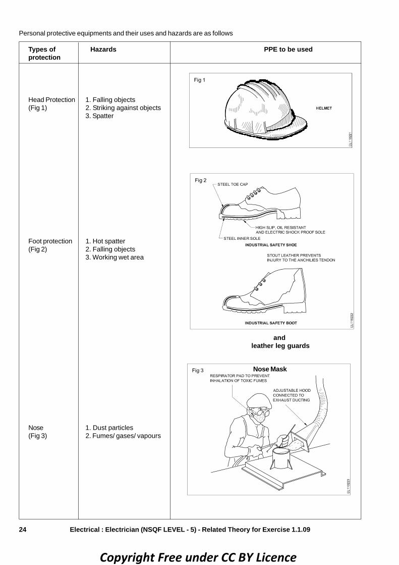
24 Electrical : Electrician (NSQF LEVEL - 5) - Related Theory for Exercise 1.1.09
Personal protective equipments and their uses and hazards are as follows
Types of Hazards PPE to be usedprotection
Head Protection 1. Falling objects(Fig 1) 2. Striking against objects
3. Spatter
Foot protection 1. Hot spatter(Fig 2) 2. Falling objects
3. Working wet area
Nose 1. Dust particles(Fig 3) 2. Fumes/ gases/ vapours
Nose Mask
and leather leg guards
Copyright Free under CC BY Licence

25Electrical : Electrician (NSQF LEVEL - 5) - Related Theory for Exercise 1.1.09
Types of Hazards PPE to be usedprotection
Face Protection 1. Spark generated during(Fig 6, Fig 7) Welding, grinding
2. Welding spatter striking3. Face protection from UV rays
andFace Shield
Head Shield with or without Ear MuffHelmets with screen for welders
Eye protection 1. Flying dust particles(Fig 5, Fig 6) 2. UV rays, IR rays heat and
High amount of visible radiation
Googgles
andFace ShieldHead ShieldHand Shield
Hand protecion 1. Heat burn due to direct contact
(Fig 4) 2. Blows sparks moderate heat3. Electric shock
Hand Gloves
Copyright Free under CC BY Licence

26 Electrical : Electrician (NSQF LEVEL - 5) - Related Theory for Exercise 1.1.09
Body protection 1. Hot particles(Fig 8, Fig 9)
Types of Hazards PPE to be usedprotection
Ear protection 1. High noise level(Fig 7)
Body Guard
Head shield with Ear muff
andEar plugEar Muff
Copyright Free under CC BY Licence

27
Quality of PPE’sPPE must meet the following criteria with regard to itsquality-provide absolute and full protection against possiblehazard and PPE’s be so designed and manufactured outof materials that it can withstand the hazards against whichit is intended to be used.
Selection of PPE’s requires certain conditions• Nature and severity of the hazard
• Type of contaminant, its concentration and location ofcontaminated area with respect to the source ofrespirable air
• Expected activity of workman and duration of work,comfort of workman when using PPE
• Operating characteristics and limitations of PPE
• Easy of maintenance and cleaning
• Conformity to Indian/ International standards andavailability of test certificate.
Proper use of PPEsHaving selected the proper type of PPE, it is essentialthat the workman wears it. Often the workman avoids usingPPE. The following factors influence the solution to thisproblem.
• The extent to which the workman understands thenecessity of using PPE
• The ease and comfort with which PPE can be wornwith least interference in normal work procedures
• The available economic, social and disciplinarysanctions which can be used to influence the attitudeof the workman
• The best solution to this problem is to make 'wearingof PPE' mandatory for every employee.
• In other places, education and supervision need to beintensified. When a group of workmen are issued PPEfor the first time.
Occupational health hazard and safetySafetySafety means freedom or protection from harm, danger,hazard, risk, accident, injury or damage.
Occupational health and safety• Occupational health and safety is concerned with
protecting the safety, health and welfare of peopleengaged in work or employment.
• The goal is to provide a safe work environment and toprevent hazards.
• It may also protect co-workers, family members,employers, customers, suppliers, nearby communities,and other members of the public who are affected bythe workplace environment.
• It involves interactions among many related areas,including occupational medicine, occupational (orindustrial) hygiene, public health, and safetyengineering, chemistry, and health physics.
Need of occupational health and safety• Health and safety of the employees is an important
aspect of a company's smooth and successfulfunctioning.
• It is a decisive factor in organizational effectiveness. Itensures an accident-free industrial environment.
• Proper attention to the safety and welfare of theemployees can yield valuable returns.
• Improving employee morale
• Reducing absenteeism
• Enhancing productivity
• Minimizing potential of work-related injuries andillnesses
• Increasing the quality of manufactured products and/or rendered services.
Occupational (Industrial) hygiene• Occupational hygiene is anticipation, recognition,
evaluation and control of work place hazards (or)environmental factors (or) stresses
• This is arising in (or) from the workplace.
• Which may cause sickness, impaired health and wellbeing (or) significant discomfort and inefficiency amongworkers.
Anticipation (Identification): Methods of identificationof possible hazards and their effects on health
Recognition (Acceptance): Acceptance of ill-effects ofthe identified hazards
Evaluation (Measurement & Assessment): Measuringor calculating the hazard by Instruments, Air samplingand Analysis, comparison with standards and takingjudgement whether measured or calculated hazard is moreor less than the permissible standard.
Control of workplace hazards: Measures likeEngineering and Administrative controls, medicalexamination, use of Personal Protective Equipment (PPE),education, training and supervision
Occupational hazards"Source or situation with a potential for harm in terms ofinjury or ill health, damage to property, damage to theworkplace environment, or a combination of these".
Types of occupational health hazards• Physical Hazards
• Chemical Hazards
• Biological Hazards
• Physiological Hazards
Electrical : Electrician (NSQF LEVEL - 5) - Related Theory for Exercise 1.1.09
Copyright Free under CC BY Licence

28
• Mechanical Hazards
• Electrical Hazards
• Ergonomic Hazards.
1 Physical hazards• Noise
• Heat and cold stress
• Vibration
• Radiation (ionising & Non-ionising)
• Illumination etc.,
2 Chemical hazards• Inflammable
• Explosive
• Toxic
• Corrosive
• Radioactive
3 Biological hazards• Bacteria
• Virus
• Fungi
• Plant pest
• Infection.
4 Physiological• Old age
• Sex
• Ill health
• Sickness
• Fatigue.
5 Psychological• Wrong attitude
• Smoking
• Alcoholism
• Unskilled
• Poor discipline
- absentism
- disobedience
- aggressive behaviours
• Accident proneness etc,
• Emotional disturbances
- voilence
- bullying
- sexual harassment
6 Mechanical• Unguarded machinery
• No fencing
• No safety device
• No control device etc.,
7 Electrical• No earthing
• Short circuit
• Current leakage
• Open wire
• No fuse or cut off device etc,
8 Ergonomic• Poor manual handling technique
• Wrong layout of machinery
• Wrong design
• Poor housekeeping
• Wrong tools etc,
Safety Slogan A Safety rule breaker, is an accident maker
Electrical : Electrician (NSQF LEVEL - 5) - Related Theory for Exercise 1.1.09
Copyright Free under CC BY Licence

29
Electrical Related Theory for Exercise 1.1.10Electrician - Safety Practice and Hand Tools
Guidelines for cleanliness of workshop and maintenanceObjectives: At the end of this lesson you shall be able to• state the necessity of cleaning of workshop• list the benefits of shop floor cleaning and maintenance• state the common cleaning procedure in workshop• list the different methods of cleaning process• state the concept of 5s techniques and their description• list the benefits of 5s techniques.
Cleaning processCleaning is the process of removal of unwanted matter,contaminants or pollutants from the environment or theprevention of soiling thus it should be - GREEN clean.
‘Green-cleaning” means the need to clean up the cleaningprocess and protect themselves.
Cleaning is about removing pollution, notadditing to it.
Necessity of cleaning of workshopA clean workplace ensures safety and health of employeesand injuries can be prevented by taking action to ensure aclean, safe work environment.
Reasons for cleaning the workplace• Cleaning of dry floors essentially to prevent slips and
falls in the workplace.
• Disinfectants prevents the spread germs and illness,because it will stop germs in their tracks.
• Proper air filteration reduces the exposures of hazardoussubstances like dust and vapors.
• Cleaning of light fixtures improve lighting efficiency.
• Using green cleaning products which is safer for bothemployees and the environment.
• Proper disposal of waste and recyclable materialskeeps work areas clean.
Benefits of a shop floor maintenance• Productive can be improved.
• Improves operator’s efficiencies.
• Improves the support operations such as replacementmoves and finished goods.
• Reduction of scrap.
• Manufacturing process can be controlled effectively.
• Reduction of downtime due to better machine and toolmanitoring.
• Better control of inventory process.
Common cleaning procedure• Before starting to clean, read the product and equipment
labels and usage instructions.
• Wear recommended Personal Potective Equipment(PPE) like rubber or surgical type gloves, goggles, dustmask or respirator, earplugs etc.
• Cleaning must be performed to prevent or remove soils,contaminants or pollutants.
• Select and use less toxic products and this system isknown as “Standard Operating Procedures” (SOPs).
• SOPs is the part of the over all operation and maintenanceplan for bending.
Other different methods of cleaning are
– Sprinkling
– Spraying
– Power wash process
– Boiling under pressure
– Carbon dioxide cleaning
– Pre cleaning
– Main cleaning
– Rinsing
– Drying etc,
For improving the standardising the way to clean StandardOperating Procedures (SOPs) as a set of writtenguidelines must be provided to the cleaners which includes
1 Cleaning procedures
2 Chemical handling and tracking requirements
3 Communication protocols
4 Training and inspection programs
5 Reporting and record keeping procedures.
The above guidelines should be made available to allcleaning personel and occupants.
Copyright Free under CC BY Licence
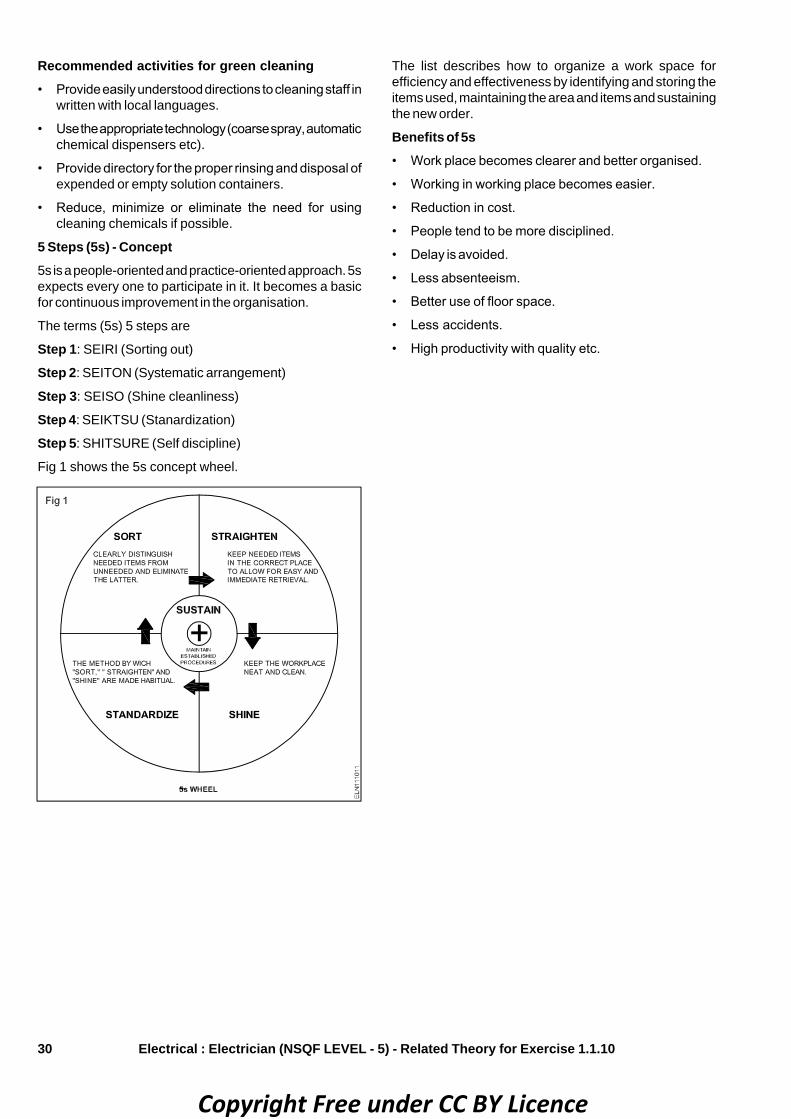
30
Recommended activities for green cleaning• Provide easily understood directions to cleaning staff in
written with local languages.
• Use the appropriate technology (coarse spray, automaticchemical dispensers etc).
• Provide directory for the proper rinsing and disposal ofexpended or empty solution containers.
• Reduce, minimize or eliminate the need for usingcleaning chemicals if possible.
5 Steps (5s) - Concept5s is a people-oriented and practice-oriented approach. 5sexpects every one to participate in it. It becomes a basicfor continuous improvement in the organisation.
The terms (5s) 5 steps are
Step 1: SEIRI (Sorting out)
Step 2: SEITON (Systematic arrangement)
Step 3: SEISO (Shine cleanliness)
Step 4: SEIKTSU (Stanardization)
Step 5: SHITSURE (Self discipline)
Fig 1 shows the 5s concept wheel.
The list describes how to organize a work space forefficiency and effectiveness by identifying and storing theitems used, maintaining the area and items and sustainingthe new order.
Benefits of 5s• Work place becomes clearer and better organised.
• Working in working place becomes easier.
• Reduction in cost.
• People tend to be more disciplined.
• Delay is avoided.
• Less absenteeism.
• Better use of floor space.
• Less accidents.
• High productivity with quality etc.
Electrical : Electrician (NSQF LEVEL - 5) - Related Theory for Exercise 1.1.10
Copyright Free under CC BY Licence
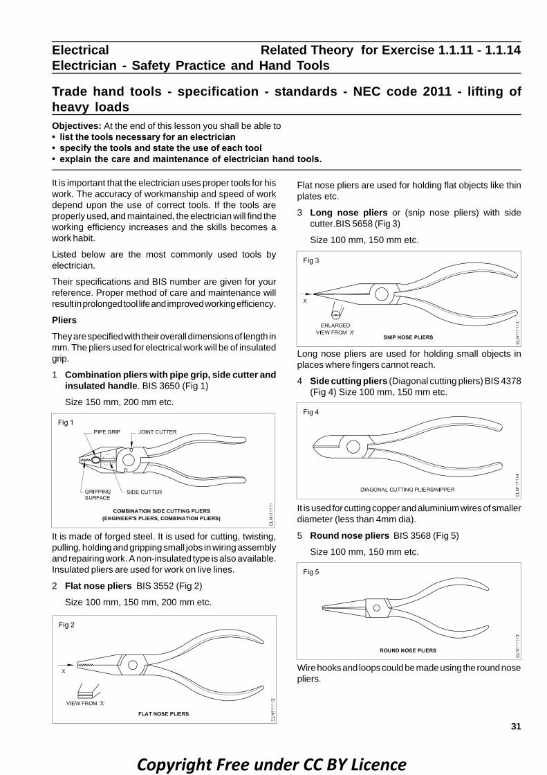
31
Electrical Related Theory for Exercise 1.1.11 - 1.1.14Electrician - Safety Practice and Hand Tools
Trade hand tools - specification - standards - NEC code 2011 - lifting ofheavy loadsObjectives: At the end of this lesson you shall be able to• list the tools necessary for an electrician• specify the tools and state the use of each tool• explain the care and maintenance of electrician hand tools.
It is important that the electrician uses proper tools for hiswork. The accuracy of workmanship and speed of workdepend upon the use of correct tools. If the tools areproperly used, and maintained, the electrician will find theworking efficiency increases and the skills becomes awork habit.
Listed below are the most commonly used tools byelectrician.
Their specifications and BIS number are given for yourreference. Proper method of care and maintenance willresult in prolonged tool life and improved working efficiency.
PliersThey are specified with their overall dimensions of length inmm. The pliers used for electrical work will be of insulatedgrip.
1 Combination pliers with pipe grip, side cutter andinsulated handle. BIS 3650 (Fig 1)
Size 150 mm, 200 mm etc.
It is made of forged steel. It is used for cutting, twisting,pulling, holding and gripping small jobs in wiring assemblyand repairing work. A non-insulated type is also available.Insulated pliers are used for work on live lines.
2 Flat nose pliers BIS 3552 (Fig 2)
Size 100 mm, 150 mm, 200 mm etc.
Flat nose pliers are used for holding flat objects like thinplates etc.
3 Long nose pliers or (snip nose pliers) with sidecutter.BIS 5658 (Fig 3)
Size 100 mm, 150 mm etc.
Long nose pliers are used for holding small objects inplaces where fingers cannot reach.
4 Side cutting pliers (Diagonal cutting pliers) BIS 4378(Fig 4) Size 100 mm, 150 mm etc.
It is used for cutting copper and aluminium wires of smallerdiameter (less than 4mm dia).
5 Round nose pliers BIS 3568 (Fig 5)
Size 100 mm, 150 mm etc.
Wire hooks and loops could be made using the round nosepliers.
Copyright Free under CC BY Licence

32
Care and maintenance of pliers• Do not use pliers as hammers.
• Do not use pliers to cut large sized copper or aluminiumwires and hard steel wires of any size.
• While using the pliers avoid damages to the insulationof hand grips.
• Lubricate hinged portions.
6 Screwdriver BIS 844 (Fig 6)
The screwdrivers used for electrical works generally haveplastic handles and the stem is covered with insulatingsleeves. The size of the screw driver is specified by itsblade length in mm and nominal screwdriver’s point size(thickness of tip of blade) and by the diameter of the stem.
eg. 75 mm x 0.4 mm x 2.5 mm
150 mm x 0.6 mm x 4 mm
200 mm x 0.8 mm x 5.5 mm etc.
The handle of screwdrivers is either made of wood orcellulose acetate.
Screwdrivers are used for tightening or loosening screws.The screwdriver tip should correctly fit the grooves of thescrew to have maximum efficiency and to avoid damage tothe screw heads.
As the length of the screw driver is proportional to theturning force, for small work choose a suitable small sizedscrewdriver and vice versa.
Star-head ScrewdriverIt is used for driving star headed screws.
Care and maintenance• Never use a screwdriver as a lever to apply force as this
action will make the stem to bend and the use of thescrew driver will be lost.
• Keep the tip in correct shape and in rare cases it couldbe grinded to shape.
7 Neon tester BIS 5579 - 1985 (Fig 7)
It is specified with its working voltage range 100 to 250 voltsbut rated to 500 V.
It consists of a glass tube filled with neon gas, andelectrodes at the ends. To limit the current within 300
micro-amps at the maximum voltage, a high value resistanceis connected in series with one of the electrodes. It mayhave a tip like a probe or screwdriver at one end. Thepresence of supply is indicated by the glow of the lampwhen the tip is touched on the live supply and the brasscontact in the other end of neon tester is touched by hand.
Care and maintenance• Never use the neon tester for voltage higher than the
specified range.
• While testing see the circuit is completed through thebody. In case if you are using rubber soled shoes, theearthing of the body could be provided by touching thewall by one hand.
• Use the screwdriver tipped neon tester for light dutywork only.
8 Electrician’s knife (Double blade) (Fig 8)
The size of the knife is specified by its largest blade lengtheg. 50 mm, 75 mm.
It is used for skinning the insulation of cables and cleaningthe wire surface. One of the blades which is sharp is usedfor skinning the cable and the rough edged blade is usedfor cleaning the surface of the wires.
Care and maintenance• Do not use the knife for cutting wires.
• Keep it free from rust.
• Keep one of the blades in a sharp condition.
• Fold the knife blade when not in use.
Electrical : Electrician (NSQF LEVEL - 5) - Related Theory for Exercise 1.1.11 - 1.1.14
Copyright Free under CC BY Licence

33
9 Four-fold box wood rule 600mm (Fig 9)
Used for measuring short lengths. To be kept in foldedcondition when not in use.
10 Hammer ball pein (Fig 10)
The size of the hammer is expressed in weight of the metalhead. Eg.125 gms, 250 gms etc.
The hammer is made out of special steel and the strikingface is tempered. Used for nailing, straightening, andbending work. The handle is made of hard wood.
Care and maintenance• Do not use a hammer with a loose handle.
• The face of the hammer must be free from oil, greaseand mushrooms.
11 Try-square (Engineer’s square) (Fig 11) BIS 2103
This is specified by its blade length.
Eg. 50 mm x 35 mm
100 mm x 70 mm
150 mm x 100 mm etc.
There are two types; one is the bevelled edge with stockand the other is the flat edge without stock. It is used tocheck whether the object is plane, perpendicular and atright angle. Two straight blades set at right angles to eachother constitute the try-square. The steel blade is riveted tothe stock. The stock is made of cast iron. The stock shouldbe set against the edge of the job.
Do not use it as a hammer.12 Firmer chisel (Fig 12)
It has a wooden handle and a cast steel blade of 150 mmlength. Its size is measured according to the width of theblade eg. 6 mm, 12 mm, 18 mm, 25 mm. It is used forchipping, scraping and grooving in wood.
Care and maintenance• Do not use it for driving screws.
• Use mallet for chiseling.
• Grind on a water stone and sharpen on an oilstone.
• Do not use it in places where nails are driven.
13 Tenon-saw (Fig 13) BIS 5123, BIS 5130, BIS 5031
Generally the length of a tenon-saw will be 250 or 300 mm.and has 8 to 12 teeth per 25.4 mm and the blade width is10 cm. It is used for cutting thin, wooden accessories likewooden batten, casing capping, boards and round blocks.
Electrical : Electrician (NSQF LEVEL - 5) - Related Theory for Exercise 1.1.11 - 1.1.14
Copyright Free under CC BY Licence

34
Care and maintenance• Keep free from rust.
• Apply grease when not in use.
14 Wood rasp file (Fig 14) BIS 1931
17 Bradawl square pointed (or poker) (Fig 17)
BIS 10375 - 1982
It is used for filing wooden articles where finish is notimportant. Wood rasp files are of half round shape. Theyhave sharp coarse single cut teeth.
15 Files (Fig 15) BIS 1931
These are specified by their nominal length.
Eg.150 mm, 200 mm, 250 mm 300 mm etc.
These files have different numbers of teeth designed to cutonly in the forward stroke. They are available in differentlengths and sections (Eg.flat, half round, round, square,triangular), grades like rough, bastard second cut andsmooth and cuts like single and double cut.
These files are used to remove fine chips of material frommetals. The body of the file is made of cast steel andhardened except the tang.
Care and maintenance• Never use the file as a hammer.
• Do not use the file without the handle.
• Do not throw a file since the teeth get damaged.
16 Plumb bob (Fig 16)
It has a pointed tip with a centre hole at the top for attachinga string as shown in Fig 16. It is used for marking verticallines on the wall.
Care and maintenanceDo not drop to the ground.
It is specified by its length and diameter eg. 150 mm x 6mm.
It is a long sharp tool used for making pilot holes on woodenarticles to fix screws.
Care and maintenance• Do not use it on metals for making holes.
• Keep it in good sharpened condition.
18 Gimlet (Fig 18)
It is used for boring small holes on wooden articles. It hasa wooden handle and a boring screwed edge. The size ofit depends upon its diameter. Eg. 3 mm, 4 mm, 5 mm, 6mm.
Care and maintenance• Do not use it without the handle.
• Do not use it on nails.
• Keep it straight while making holes, otherwise thescrewed portion can get damaged.
Electrical : Electrician (NSQF LEVEL - 5) - Related Theory for Exercise 1.1.11 - 1.1.14
Copyright Free under CC BY Licence
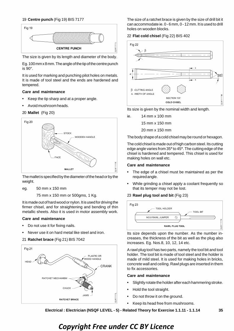
35
19 Centre punch (Fig 19) BIS 7177
The size is given by its length and diameter of the body.
Eg. 100 mm x 8 mm. The angle of the tip of the centre punchis 90°.
It is used for marking and punching pilot holes on metals.It is made of tool steel and the ends are hardened andtempered.
Care and maintenance• Keep the tip sharp and at a proper angle.
• Avoid mushroom heads.
20 Mallet (Fig 20)
The mallet is specified by the diameter of the head or by theweight.
eg. 50 mm x 150 mm
75 mm x 150 mm or 500gms, 1 Kg.
It is made out of hard wood or nylon. It is used for driving thefirmer chisel, and for straightening and bending of thinmetallic sheets. Also it is used in motor assembly work.
Care and maintenance• Do not use it for fixing nails.
• Never use it on hard metal like steel and iron.
21 Ratchet brace (Fig 21) BIS 7042
The size of a ratchet brace is given by the size of drill bit itcan accommodate ie. 0 - 6 mm, 0 - 12 mm. It is used to drillholes on wooden blocks.
22 Flat cold chisel (Fig 22) BIS 402
Its size is given by the nominal width and length.
ie. 14 mm x 100 mm
15 mm x 150 mm
20 mm x 150 mm
The body shape of a cold chisel may be round or hexagon.
The cold chisel is made out of high carbon steel. Its cuttingedge angle varies from 35° to 45°. The cutting edge of thechisel is hardened and tempered. This chisel is used formaking holes on wall etc.
Care and maintenance• The edge of a chisel must be maintained as per the
required angle.
• While grinding a chisel apply a coolant frequently sothat its temper may not be lost.
23 Rawl plug tool and bit (Fig 23)
Its size depends upon the number. As the number in-creases, the thickness of the bit as well as the plug alsoincreases. Eg. Nos.8, 10, 12, 14 etc.
A rawl plug tool has two parts, namely the tool bit and toolholder. The tool bit is made of tool steel and the holder ismade of mild steel. It is used for making holes in bricks,concrete wall and ceiling. Rawl plugs are inserted in themto fix accessories.
Care and maintenance• Slightly rotate the holder after each hammering stroke.
• Hold the tool straight.
• Do not throw it on the ground.
• Keep its head free from mushrooms.
Electrical : Electrician (NSQF LEVEL - 5) - Related Theory for Exercise 1.1.11 - 1.1.14
Copyright Free under CC BY Licence

36
24 Spanner: double ended (Fig 24) BIS 2028 Care and maintenance• Use correct size spanner suitable to the size of nut and
bolt.
• Do not use a spanner as a hammer.
• While using a spanner do not strike it with a hammer.
• Prevent the grease and oil traces on its jaws.The size of a spanner is indicated so as to fit on the nuts.They are available in many sizes and shapes.
The sizes, indicated in double-ended spanners are
10-11 mm
12-13 mm
14-15 mm
16-17 mm
18-19 mm
20-22 mm.
For loosening and tightening of nuts and bolts, spannersets are used. It is made out of cast steel. They areavailable in many sizes and may have single or doubleends.
25 Ring spanner set (Fig 25) BIS 2029
The ring spanner is used in places where the space isrestricted and where high leverage is required.
26 Socket (box) spanner (Fig 26) BIS 7993, 7991, 6129
These spanners are useful at places where the nut or boltis located in narrow space or at depth.
27 Single ended open jaw adjustable spanner(Fig 27) BIS 6149
It saves time and working. The movable jaw is madeadjustable by operating a screw. It is known as a monkeywrench also. Available in 150,200,250mm etc.
28 Measuring steel tape (Fig 28)
The size will be the maximum length it can measure.Eg.Blade 12 mm wide 2 metres long.
The measuring tape is made of thin steel blade, bearingdimensions on it.
It is used for measuring the dimension of the wiringinstallation and general measurements.
Care and maintenanceHandle with great care as carelessness may spoil thegraduation.
29 Hacksaw (Fig 29) BIS 5169-1986 for frames
BIS 2594 - 1977 for blades
Electrical : Electrician (NSQF LEVEL - 5) - Related Theory for Exercise 1.1.11 - 1.1.14
Copyright Free under CC BY Licence
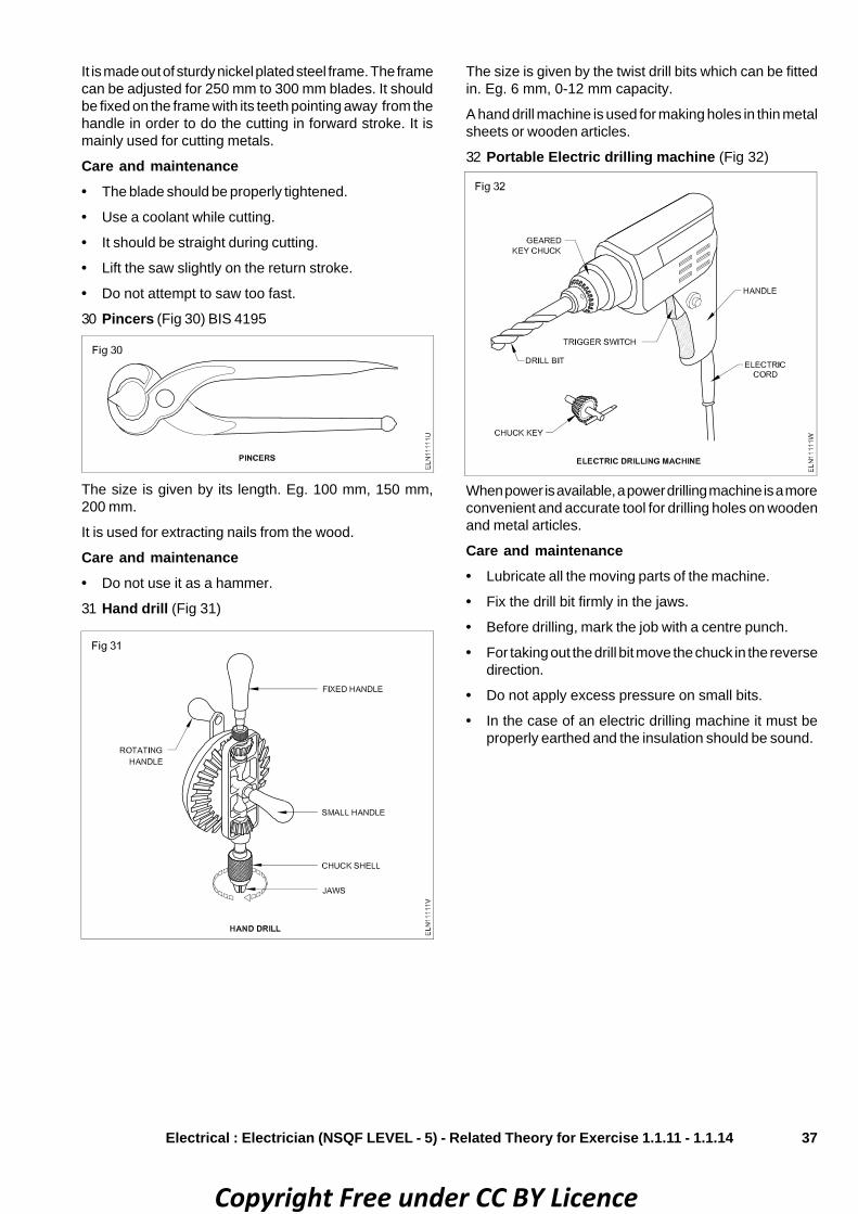
37
It is made out of sturdy nickel plated steel frame. The framecan be adjusted for 250 mm to 300 mm blades. It shouldbe fixed on the frame with its teeth pointing away from thehandle in order to do the cutting in forward stroke. It ismainly used for cutting metals.
Care and maintenance• The blade should be properly tightened.
• Use a coolant while cutting.
• It should be straight during cutting.
• Lift the saw slightly on the return stroke.
• Do not attempt to saw too fast.
30 Pincers (Fig 30) BIS 4195
The size is given by its length. Eg. 100 mm, 150 mm,200 mm.
It is used for extracting nails from the wood.
Care and maintenance• Do not use it as a hammer.
31 Hand drill (Fig 31)
The size is given by the twist drill bits which can be fittedin. Eg. 6 mm, 0-12 mm capacity.
A hand drill machine is used for making holes in thin metalsheets or wooden articles.
32 Portable Electric drilling machine (Fig 32)
When power is available, a power drilling machine is a moreconvenient and accurate tool for drilling holes on woodenand metal articles.
Care and maintenance• Lubricate all the moving parts of the machine.
• Fix the drill bit firmly in the jaws.
• Before drilling, mark the job with a centre punch.
• For taking out the drill bit move the chuck in the reversedirection.
• Do not apply excess pressure on small bits.
• In the case of an electric drilling machine it must beproperly earthed and the insulation should be sound.
Electrical : Electrician (NSQF LEVEL - 5) - Related Theory for Exercise 1.1.11 - 1.1.14
Copyright Free under CC BY Licence

38
Standard and standardisationObjectives: At the end of this lesson you shall be able to• state what is meant by standardisation and standard• state the names of various standard organisation• read and interpret the basic concept of electrical code 2011• state the types of injury caused by the improper lifting method• describe the procedure to be followed for moving heavy equipments
Standardisation can be defined as the process offormulating and applying rules for an orderly approach tospecific activity for the benefit of the user and themanufacturer, and in particular for the promotion of optimumoverall economy taking due account of functional conditionsand safety requirement.
It is based on the consolidated results of science, techniqueand experience. It determines not only the basis for thepresent but also for future development, and to keep pacewith progress.
The materials/tools/equipment produced in any countryshould be of certain standard. To meet this requirement,the international organisation for standarization(ISO) isstarted and specifies the units of measurement, technologyand symbols, products and processes, safety of personsand goods through a number of booklets coded with ISOnumber.
Standard can be defined as a formulation establishedverbally, in writing or by any other graphical method or bymeans of a model, sample or other physical means ofrepresentation to serve during a certain period of time fordefining designating or specifying certain features of a unitor basis of measurement, physical object, an action,process, method, practice, capacity, function, duty, rightof responsibility, a behaviour, an attitude a concept or aconception.
To sell Indian goods in the local and international marketcertain standardization methods are essential. The standardis specified by the Bureau of Indian Standard BIS(ISI) forvarious goods through their booklets. The BIS only certifiesa good often the product meets the specification andpasses necessary tests. The manufacturer allows to usethe BIS(ISI) mark on the product only after BIS certification.
These are a number of organisation for standardisationthroughout the world in different countries.
The standard organisation and the respective countries aregiven below:
BIS - Bureau of Indian Standard (ISI) - India
ISO - International standard Organisation
JIS - Japanese Industrial Standard - Japan
BSI - British Standards Institution BS(S) - Britain
DIN - Deutche Industrie Normen - Germany
GOST - Russian
ASA - American standards association - America
Advantages of BIS(ISI) certification marks scheme:A number of advantages accrue to different sectors ofeconomy from the BIS(ISI) certification marks scheme.
To manufacturers• Streamlining of production processes and introduction
of quality control system.• Independent audit of quality control system by BIS• Reaping of production economics accruing from
standardization• Better image of products in the market, both internal
and overseas• Winning for whole-salers, retailers and stockists
consumer confidence and goodwill• Preference for ISI-marked products by organised
purchasers, agencies of Central and State Governments,local bodies, public and private sector undertakingsetc. Some organised purchasers offer even higher pricefor ISI-marked goods.
• Financial incentives offered by the Industrial DevelopmentBank of India (IDBI) and nationalised banks.
To consumers• Conformity with Indian Standards by an independent
technical, National Organisation
• Help in choosing a standard product
• Free replacement of ISI-marked products in case oftheir being found to be of substandard quality
• Protection from exploitation and deception
• Assurance of safety against hazards to life and property
To organised purchasers• Convenient basis for concluding contracts
• Elimination of the need for inspection and testing ofgoods purchased, saving time, labour and money
• Free replacement of products with ISI-mark, found to besub-standard
To exporters• Exemption from pre-shipment inspection, wherever
admissible
• Convenient basis for concluding export contracts
To export inspection authorities• Elimination of the need for exhaustive inspection of
consignments exported from the country, savingexpenditure, time and labour.
Electrical : Electrician (NSQF LEVEL - 5) - Related Theory for Exercise 1.1.11 - 1.1.14
Copyright Free under CC BY Licence

39
Introduction to National Electrical Code - 2011
National Electrical Code - 2011National electrical code describes several indian standardsdeciding with the various aspects relating to electricalinstallation practice. It is there fore recommended thatindividual parts/ sections of the code should be read inconjunction with the relevant indian standards.
There are 8 parts and each part contains number ofsections. Each section refers the description of the electricalitem/ devices, equipment etc.
Here, 20 sections of the part - 1 are described which aspectit covers
In part 1, 20 sections are there. Each sections reference isgiven below.
Section 1 part 1/ section 1 of the code describes the scopeof the NEC.
Section 2 covers definition of items with references.
Section 3 covers graphical symbols for diagrams, lettersymbols and signs which may be referred for furtherdetails.
Section 4 covers of guidelines for preparation of diagrams,chart and tables in electro technology and for marking ofconductors.
Section 5 covers units and systems of measurement inelectro technology.
Section 6 covers standard values of AC and DC distributionvoltage preferres values of current ratings and standardsystems frequency.
Section 7 enumerates the fundamental principles of designand execution of electrical installation.
Section 8 covers guidelines for assesing the characteristicsof buildings and the electrical installation there in.
Section 9 Covers the essential design and constructionalrequirement for electrical wiring installation.
Section 10 covers guidelines and general requirementsassociated with circuit calculators.
Section 11 covers requirements of installation work relatingto building services that use electrical power.
Section 12 covers general criteria for selection ofequipment.
Section 13 covers general principles of installation andguide lines on initial testing before commissioning.
Section 14 covers general requirements associated withearthing in electrical installations. Specific requirementsfor earthing in individual installations are covered in respectiveparts of the code.
Section 15 covers guidelines on the basic electricalaspects of lightning protective systems for buildings andthe electrical installation forming part of the system.
Section 16 covers the protection requirements in lowvoltage electrical installation of buildings.
Section 17 covers causes for low power factor andguidelines for use of capacitors to improve the same inconsumer installations.
Section 18 covers the aspects to be considered forselection of equipment from energy conservation point ofview and guidence on energy audit.
Section 19 covers guidelines on safety procedures andpractices in electrical work.
Section 20 gives frequently referred tables in electricalengineering work.
The above description is part 1 only you can refer remainingparts and section for other electrical installation, itemsdevices and equipments.
Lifting and handling of loads
Many of the accidents reported involve injuries caused bylifting and carrying loads. A electrician may need to installmotors, lay heavy cables, do wiring, which may involve a lotof lifting and carrying of loads. Wrong lifting techniques canresult in injury.
A load need not necessarily be very heavy to cause injury.The wrong way of lifting may cause injury to the musclesand joints even though the load is not heavy.
Further injuries during lifting and carrying may be causedby tripping over an object and falling or striking an objectwith a load.
Types of injury and how to prevent them?Cuts and abrasionsCuts and abrasions are caused by rough surfaces andjagged edges:
- By splinters and sharp or pointed projections. (Fig 1)
Leather hand gloves will usually be sufficient for protection,but the load should be checked to make sure of this, sincelarge or heavy loads may involve body contact as well.
Electrical : Electrician (NSQF LEVEL - 5) - Related Theory for Exercise 1.1.11 - 1.1.14
Crushing of feet or handsFeet or hands should be so positioned that they will not betrapped by the load. Timber wedges can be used whenraising and lowering heavy loads to ensure fingers andhands are not caught and crushed.
Copyright Free under CC BY Licence

40
4 To raise the load, first straighten the legs. This ensuresthat the lifting strain is being correctly transmitted andis being taken by the powerful thigh muscles andbones.
5 Look directly ahead, not down at the load whilestraightening up, and keep the back straight; this willensure a smooth, natural movement without jerking orstraining (Fig 5)
3 Loads high require the arms to be extended in front ofthe body, place more strain on the back and stomach.
4 The absence of hand holds or natural handling pointscan make it difficult to raise and carry the object.
Correct manual lifting techniques1 Approach the load squarely, facing the direction of
travel
2 The lift should start with the lifter in a balanced squattingposition, with the legs slightly apart and the load to belifted held close to the body.
3 Ensure that a safe firm hand grip is obtained. Before theweight is taken, the back should be straightened andheld as near the vertical position as possible. (Fig 4)
Safety shoes with steel toe caps will protect the feet.(Fig 2)
Strain to muscles and jointsStrains to muscles and joints may be the result of:
- Lifting a load which is too heavy, or of lifting incorrectly.
Sudden and awkward movements such as twisting orjerking during a lift can put severe strain on muscles.
'Stoop lifting' - lifting from a standing position with the backrounded increases the chance of back injury.
The human spine is not an efficient weight lifting machineand can be easily damaged if incorrect techniques areused.
The stress on a rounded back can be about sixtimes greater than if the spine is kept straight.Fig 3 shows an example of stoop lifting.
Electrical : Electrician (NSQF LEVEL - 5) - Related Theory for Exercise 1.1.11 - 1.1.14
Preparaing to liftLoad which seems light enough to carry at first will becomeprogressively heavier, the farther you have to carry it.
The person who carries the load should always be able tosee over or around it.
The weight that a person can lift will vary according to:
- Age
- Physique, and
- Condition
It will also depend on whether one is used to lifting andhandling heavy loads.
What makes an object difficult to lift and carry?
1 Weight is not the only factor which makes it difficult tolift and carry.
2 The size and shape can make an object awkward tohandle.
6 To complete the lift, raise the upper part of the body tothe vertical position. When a load is near to an individual'smaximum lifting capacity it will be necessary to lean
Copyright Free under CC BY Licence

41
back on the hips slightly (to counter balance the load)before straightening up. (Fig 6)
Keeping the load well near to the body, carry it to the placewhere it is to be set down. When turning, avoid twisting fromthe waist - turn the whole body in one movement.
Lowering the loadMake sure the area is clear of any obstructions. (Fig 7)
Bend the knees to a semi-squatting position; keep theback and head erect by looking straight a head, not downat the load. It may be helpful to rest the elbows on the thighsduring the final stage of lowering.
Moving heavy equipment
Heavy equipments are moved in industry using any of thefollowing methods.
• Crane and slings
• Winches
• Machine moving platforms
• Layers and rollers
Using crane and slingsThis method is used whenever loads are to be lifted andmoved. (Fig 1)
WinchesWinches are used to pull heavy loads along the ground.They may be power-driven (Fig 2) or hand operated. (Fig 3).
Electrical : Electrician (NSQF LEVEL - 5) - Related Theory for Exercise 1.1.11 - 1.1.14
Examine the steel rope sling for any cut,abrasion, wear, fraying or corrosion.
Damaged slings must not be used.
Distribute the weight as evenly as possible between theslings when using more than one sling. (Fig 1)
Keep the slings as near to vertical as possible.
Ensure that the safe working load (SWL) of the winch isadequate for the task.
Secure the winch to a structure which is strong enough towithstand the pull.
On open ground, drive long stakes into the ground andsecure the winch to them.
Choose a suitable sling and pass it around the base of theload. Secure it to the hook of the winch.
Some heavy items have special lugs welded tothem for jacking and towing purposes.
Safety consideration
Before using any winch, check that the brakeand ratchet mechanism are in working order.Practise how to use the brakes.
Keep hands and fingers well away from the gear wheels.
Keep the bearings and gears oiled or greased.
Machine moving platformsThis is a special device made to move heavy equipment inindustry. Fig 4 shows the method of loading a heavytransformer.
Pass a suitable sling round the load at a convenient height.
Attach the sling to the hook of the winch and draw the loadon the platform until its centre of gravity lies between thefront and rear wheels.
Copyright Free under CC BY Licence

42
Lower the jacks so that the platform rests on ist wheels.
For unloading follow the procedure in the reverse order.
Using layers and rollersSometimes a load cannot be moved along the groundbecause of the irregular shape of its base or because it isnot rigid enough.
Place such a load on a flat-bottomed pallet or 'layer' restingon the round bars. (Fig 5)
Use a winch with an effective brake for thisoperation.
Electrical : Electrician (NSQF LEVEL - 5) - Related Theory for Exercise 1.1.11 - 1.1.14
Ensure the bars (rollers) are long enough to project at eachside of the load, for ease of handling.
They should be large enough to roll easily over any unevensurface along the route but should be small enough to behandled easily.
Two or three bars of equal diameter aresufficient for most loads but if four or more areused, the load may be moved faster as there isno delay when moving the rear bar to the front.(Fig 5)
Move the load by using a crowbar as shown in Fig 6. Keepthe crowbar at the end of the pallet with an angle and a firmgrip on the ground. Apply the force at the top of the bar asshown.
When a load is on rollers, only shallow slopescan be negotiated.Hold the load in check all the time if it is on theslope.
To negotiate a corner on rollers
For a moderate load, insert one roller a little larger indiameter than the others as the corner is approached.
When this roller is under the centre of gravity of the load,the load can be rocked to and fro on the roller and swivelledaround sideways. (Fig 7)
For heavier loads
Stop the load on the roller at the beginning of the corner.
Twist the load round on the rollers by pushing the sides withcrowbars until the load is just over the ends of the rollers.(Fig 8)
Place some rollers at an angle to the front of the load.(Fig 9)
Push the load forward on to these rollers.
Twist the load further round and place the freed rollers infront of and at an angle to the load.
Continue until the load is pointing in the desired direction.
Copyright Free under CC BY Licence
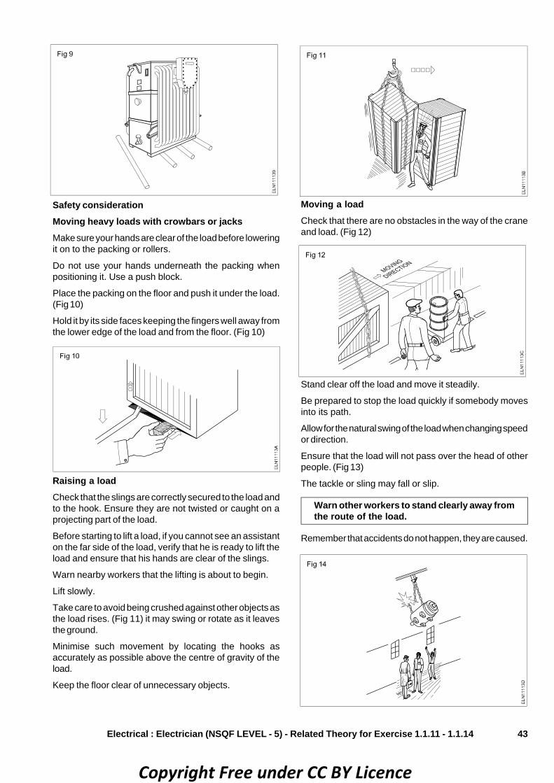
43
Safety considerationMoving heavy loads with crowbars or jacksMake sure your hands are clear of the load before loweringit on to the packing or rollers.
Do not use your hands underneath the packing whenpositioning it. Use a push block.
Place the packing on the floor and push it under the load.(Fig 10)
Hold it by its side faces keeping the fingers well away fromthe lower edge of the load and from the floor. (Fig 10)
Moving a loadCheck that there are no obstacles in the way of the craneand load. (Fig 12)
Stand clear off the load and move it steadily.
Be prepared to stop the load quickly if somebody movesinto its path.
Allow for the natural swing of the load when changing speedor direction.
Ensure that the load will not pass over the head of otherpeople. (Fig 13)
The tackle or sling may fall or slip.
Warn other workers to stand clearly away fromthe route of the load.
Remember that accidents do not happen, they are caused.
Electrical : Electrician (NSQF LEVEL - 5) - Related Theory for Exercise 1.1.11 - 1.1.14
Raising a loadCheck that the slings are correctly secured to the load andto the hook. Ensure they are not twisted or caught on aprojecting part of the load.
Before starting to lift a load, if you cannot see an assistanton the far side of the load, verify that he is ready to lift theload and ensure that his hands are clear of the slings.
Warn nearby workers that the lifting is about to begin.
Lift slowly.
Take care to avoid being crushed against other objects asthe load rises. (Fig 11) it may swing or rotate as it leavesthe ground.
Minimise such movement by locating the hooks asaccurately as possible above the centre of gravity of theload.
Keep the floor clear of unnecessary objects.
Copyright Free under CC BY Licence

44
File : File is a filing tool, which is used to file the roughsurface & smooth surface on metals
File specification: Files are specified according to their
• length
• grade
• cut
• shape
Electrical Related Theory for Exercise 1.2.15 & 1.2.16Electrician - Workshop practice (Allied trade)
Fitting tools - marking tools - specification - grades - usesObjectives : At the end of this lesson you shall be able to• state the different types of files and their grades, shapes, specification and application.• state the different cuts of files and their uses• state the parts of file
Length is the distance from the tip to the heel (Fig 1). Itmay be 300mm, 250mm, 200mm,150mm or 100mm.
Rough, bastard, second cut, smooth and dead smooth arethe different grades of files commonly available.
A rough file is used for removing more quantity of metalquickly. (Fig 2a)
A bastard file is used for ordinary filing purposes. (Fig 2b)
A second cut file is used for good finishing purposes.(Fig 2c)
A smooth file is used for removing less metal and for givinggood surface finish. (Fig 2d)
A dead smooth file is used for high degree finishing.(Fig 2e)
Cut of file: The rows of teeth determine the cut of a file.
Types of cutSingle cut, double cut, rasp cut and curved cut are thedifferent types of cuts of files.
Single cut: A single cut file has a single row of teeth in onedirection on the face of the file at an angle of 60° and thisfile is used for filing soft material such as lead, tin,aluminium etc. (Figs 3 & 4)
Double cut: A double cut file has rows of teeth in twodirections across each other, one at an angle of 50° to 60°,another row at 70° which is used to file hard materials suchas steel, brass, bronze, etc. (Fig 5)
Rasp cut: This has individual, sharp, pointed teeth in a line,and is useful for filing wood, leather and other soft materi-als. These files are available only in half-round shape.(Fig 6)
Copyright Free under CC BY Licence

45
Curved cut: These files have deeper cutting action, andare useful for filing soft materials like - aluminium, tin,copper and plastic. These are available only in flat shape.(Fig 7)
Electrical : Electrician (NSQF LEVEL - 5) - Related Theory for Exercise 1.2.15 & 1.2.16
The selection of the type of cut is based on the material tobe filed. Single cut files are used for filing soft materials. Butcertain special files, for example - those used for sharpeningsaws, are also of single cut.
Shape: The various shapes of files with their applicationare shown below. The cross-section drawn in the file refersto the shape of the file. (Fig 8)
Parts of file
File : A file is a cutting tool with multiple cutting edges usedfor filing different materials.
Parts of a file (Refer Fig 1 below)
Tip or point: This is the end of the file opposite to tang.
Face or side: The broad part of the file with teeth cut on it.
Edge: The thin part of the file with a simple row of parallelteeth.
Heel: It is the broad part of the file without teeth.
Shoulder : It is the curved part of a file separating the tangfrom the body.
Tang: Narrow and thin part of a file which fits into thehandle.
Handle: The part fitted to the tang to hold and use the file.
Bench viceObjectives: At the end of this lesson you shall be able to• name the parts and state the uses of a bench vice• specify the size of a bench vice• state the uses of vice clamps.
Bench vice: Vices are used for holding workpieces. Theyare available in different types.
The vice used for bench work is the bench vice (Engineer'svice).
A bench vice is made of cast iron or cast steel, and it isused to hold work for filing, sawing, threading and otherhand operations. (Fig 1)
The size of the vice is stated by the width of the jaws.
Parts of a bench vice (Fig 2)
• Fixed jaw (1)
• Movable jaw (2)
• Hard jaw (3)
Copyright Free under CC BY Licence

46
• cheek
• eyehole
Face: Face is the striking portion. A slight convexity isgiven to it, to avoid digging of the edge.
Peen: Peen is the other end of the head. It is used forshaping and forming work like riveting and bending. Thepeen is of different shapes. (Fig 3) They are:
The box nut and the spring are the internal parts.
Vice clamps or soft jaws: To hold a finished work use softjaws (vice clamps), (Fig 3) made of aluminium over theregular hard jaws. This will protect the work surface fromdamage. Do not over-tighten the vice so as to preventdamage to the spindle.
HammerObjectives: At the end of this lesson you shall be able to• state the uses of an engineer's hammer• name the parts of an engineer's hammer and state their functions• name the types of engineer's hammers with specifications
Hammer: Engineer's hammer is a hand tool used forvarious striking purposes like punching, bending, straight-ening, chipping, forging and riveting. (Fig 1)
Electrical : Electrician (NSQF LEVEL - 5) - Related Theory for Exercise 1.2.15 & 1.2.16
Major parts of a hammer (Fig 2)• Head• Handle
The head is made of drop-forged carbon steel, and thewooden handle must be capable of absorbing shock.
The parts of the hammer head are:
• face
• peen
• Spindle (4)
• Handle (5)
• Box nut (6)
• Spring (7)
Copyright Free under CC BY Licence

47
Specifications: The face and peen are hardened.
The cheek is left soft.
Engineer's hammers are specified by the weight of thehead and shape of the peen. The weight varies from 125gms to 1.5 kg.
The weight of the engineer's hammer used for markingpurposes is 250 gms.
The ball peen hammer is used for general work in machinefitting shops.
Before using a hammer:
• make sure the handle is properly fitted
• select the correct weight of hammer suitable for thetype of work
• check the head and handle for any crack
• ensure the face of the hammer is free from oil or grease.
Parts of a chisel (Refer Fig 2)
– Head (not hardened) (1)
– Body (2)
– Point or cutting edge (3)
Chisels are made from high carbon steel or chrome-vanadium steel. The cross-section of chisels is usuallyhexagonal or octagonal.
Common types of chisels• Flat chisel
• Cross-cut chisel
• Half-round nose chisel
• Diamond point chisel
Flat chisels are used to:
• remove metal from large flat surfaces
• chip excess metal off from welded joints and castings
• part off metal after chain drilling. (Fig 1)
Cross-cut or cape chisels are used for cutting keyways,grooves and slots. (Fig 3)
Half round, nose chisels are used for cutting curved grooves(oil grooves). (Fig 4)
Diamond point chisels are used for squaring materials atthe corners. (Fig 5)
Electrical : Electrician (NSQF LEVEL - 5) - Related Theory for Exercise 1.2.15 & 1.2.16
• ball peen
• cross-peen
• straight peen
Cheek: Cheek is the middle portion of the hammer head.The weight of the hammer is stamped here.
Eyehole: Eyehole is meant for fixing the handle. It isshaped to fix the handle rigidly. The wedge fixes the handlein the eyehole. (Fig 4)
ChiselObjectives: At the end of this lesson you shall be able to• list the uses of a cold chisel• name the parts of a cold chisel and it’s types• state the different types of hacksaw frames, blades and their uses.
The cold chisel is a hand cutting tool used by fitters forchipping and cutting operations.
Chipping is an operation of removing excess metal with thehelp of a chisel and hammer. (Fig 1) The chipped surfacesbeing rough, they should be finished by filing.
Copyright Free under CC BY Licence

48
Web chisels/punching chisels are used for separatingmetals after chain drilling. (Fig 6)
Chisels are specified according to the:• length• width of the cutting edge• type• cross-section of the body.
The length of chisels ranges from 150 mm to 400 mm.
The width of the cutting edge varies according to the typeof chisels.
Hacksaw frame and bladeThe hand hacksaw is used along with a blade to cut metalsof different sections. It is also used to cut slots andcontours.
Types of hacksaw framesBold frame: Only a particular standard length of blade canbe fitted.
Adjustable frame (flat): Different standard lengths ofblades can be fitted.
Adjustable frame tubular type (Fig 1): This is the mostcommonly used type. It gives a better grip and control whilesawing.
Hacksaw blades : The hacksaw blade is a thin, narrow,steel band with teeth and two pin holes at the ends. It is
Electrical : Electrician (NSQF LEVEL - 5) - Related Theory for Exercise 1.2.15 & 1.2.16
used along with a hacksaw frame. These blades are madeof either low alloy steel (la) or high speed steel (hs) and areavailable in standard lengths of 250mm and 300mm.
For proper working, it is necessary to have frames of rigidconstruction.
Types of hacksaw bladesAll-hard blades: The width between the pin holes ishardened all allong the length of the blade.
Flexible blades: For these types of blades only the teethare hardened. Because of their flexibility, these blades areuseful for cutting along curved lines (Fig 2).
Pitch of the blade: This is the distance between twoadjacent teeth. (Refer Fig 3) Hacksaw blades are designatedaccording to length, pitch and the type of blade
Copyright Free under CC BY Licence

49
Staggered set: Alternate teeth or groups of teeth arestaggered. This arrangement helps for free cutting, andprovides for good chip clearance. (Fig 5)
Pitches of bladesClassification Pitch
Coarse 1.8mmMedium 1.4 mm & 1.0 mmFine 0.8mm
Setting of the saw: To prevent the saw from binding whenpenetrating into the material and to allow free movement ofthe blade, the cut is to be broader than the thickness of thesaw blade. This is achieved by a proper setting of the sawteeth (Fig 4). There are two types of saw settings.
Electrical : Electrician (NSQF LEVEL - 5) - Related Theory for Exercise 1.2.15 & 1.2.16
Classification of setsPitch 0.8mm wave set.
Pitch 1.0mm wave or staggered.
Pitch over 1.0mm staggered.
Wave set: In this, the, teeth of the blade are arranged in awave-form. (Fig 6).
For satisfactory results a blade of the correctpitch should be selected and fitted correctly.
Saw blades for hacksaws are available with small and largecutting of teeth, depending on the type and size of materialthey are to cut. The size of the teeth is directly related totheir pitch, which is specified by the number of teeth per25mm of the cutting edge. Hacksaw blades are avaialablein pitches of: (Fig 7)• 14 teeth per 25 mm • 18 teeth per 25 mm• 24 teeth per 25 mm • 32 teeth per 25 mm.
Copyright Free under CC BY Licence

50
Electrical Related Theory for Exercise 1.2.17Electrician - Workshop practice (Allied trade)
Marking tools - steel rule - punches - calipers - try square - gaugesObjectives: At the end of this lesson you shall be able to• state the constructional features of an engineer's steel rule• explain the uses of the steel rule• state the maintenance aspects to be considered in respect of the steel rule.
Engineer's steel rule: When dimensions are given in adrawing without any indication about the tolerance, it hasto be assumed that measurements are to be made with asteel rule.
Material and sizes of steel rules: Steel rules are madeof spring steel or stainless steel. The edges are accuratelyground to form a straight line.
Steel rules are available in different lengths; the commonsizes are 150mm, 300mm and 600mm. (Refer Fig 1)
The surfaces of the steel rules are satin-chrome finished toreduce glare and also to prevent rusting. The engineer'srule is graduated in 10mm, 5mm, 1mm and 0.5mm. Thusthe reading accuracy of a steel rule is 0.5mm.
Graduation: The minimum graduation is 0.5mm.
Uses: Use a try square on one datum edge and measurethe distance from the other datum edge using a steel rule.(Figs 2a & b)
A steel rule is used to take the desired height for themarking surface gauge. (Fig 3)
Transfer of measurement from the steel rule to the divideris shown in Fig 4.
Steel rule is used to transfer measurements from the ruleto the odd leg calipers. (Fig 5)
Copyright Free under CC BY Licence
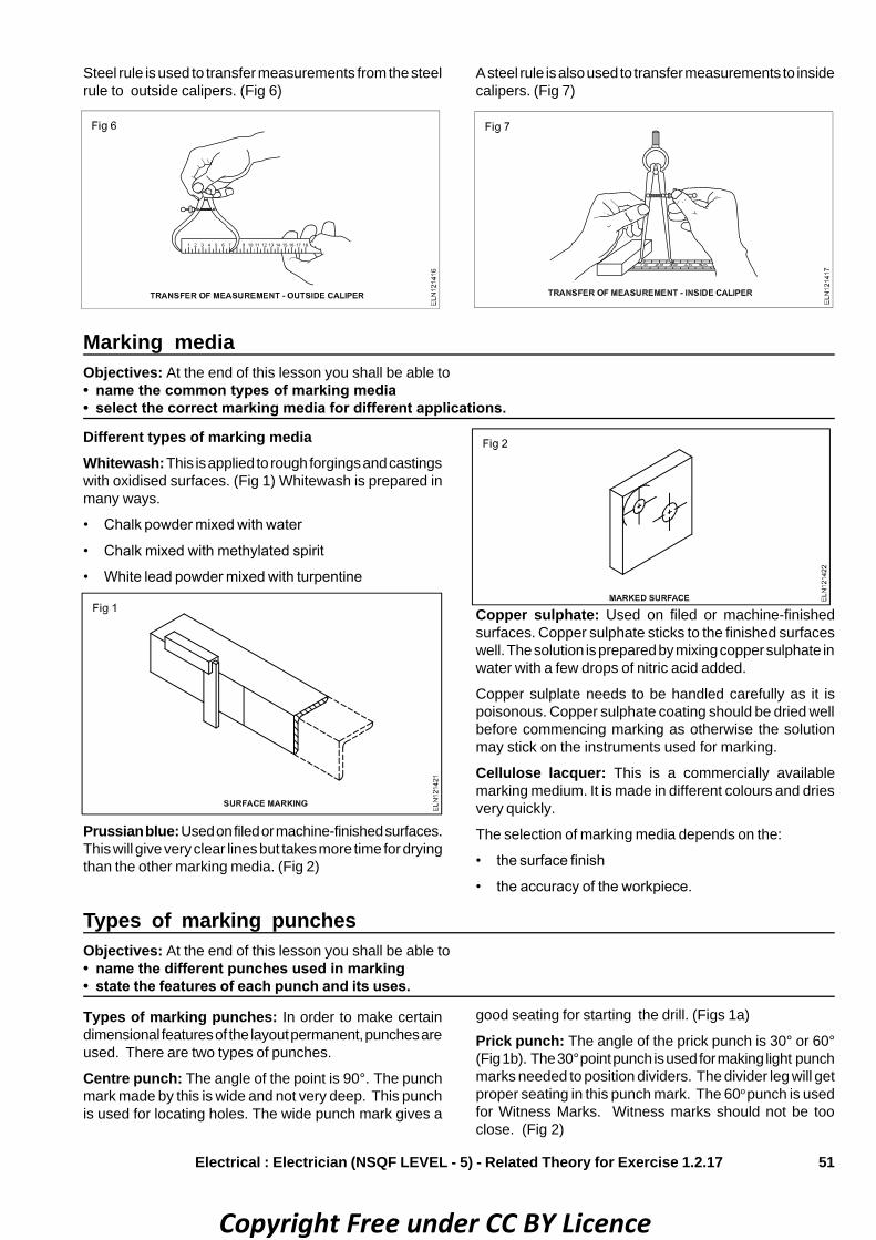
51
Steel rule is used to transfer measurements from the steelrule to outside calipers. (Fig 6)
A steel rule is also used to transfer measurements to insidecalipers. (Fig 7)
Marking mediaObjectives: At the end of this lesson you shall be able to• name the common types of marking media• select the correct marking media for different applications.
Different types of marking mediaWhitewash: This is applied to rough forgings and castingswith oxidised surfaces. (Fig 1) Whitewash is prepared inmany ways.
• Chalk powder mixed with water
• Chalk mixed with methylated spirit
• White lead powder mixed with turpentine
Copper sulphate: Used on filed or machine-finishedsurfaces. Copper sulphate sticks to the finished surfaceswell. The solution is prepared by mixing copper sulphate inwater with a few drops of nitric acid added.
Copper sulplate needs to be handled carefully as it ispoisonous. Copper sulphate coating should be dried wellbefore commencing marking as otherwise the solutionmay stick on the instruments used for marking.
Cellulose lacquer: This is a commercially availablemarking medium. It is made in different colours and driesvery quickly.
The selection of marking media depends on the:
• the surface finish
• the accuracy of the workpiece.
Prussian blue: Used on filed or machine-finished surfaces.This will give very clear lines but takes more time for dryingthan the other marking media. (Fig 2)
Types of marking punchesObjectives: At the end of this lesson you shall be able to• name the different punches used in marking• state the features of each punch and its uses.
Types of marking punches: In order to make certaindimensional features of the layout permanent, punches areused. There are two types of punches.
Centre punch: The angle of the point is 90°. The punchmark made by this is wide and not very deep. This punchis used for locating holes. The wide punch mark gives a
good seating for starting the drill. (Figs 1a)
Prick punch: The angle of the prick punch is 30° or 60°(Fig 1b). The 30°point punch is used for making light punchmarks needed to position dividers. The divider leg will getproper seating in this punch mark. The 60opunch is usedfor Witness Marks. Witness marks should not be tooclose. (Fig 2)
Electrical : Electrician (NSQF LEVEL - 5) - Related Theory for Exercise 1.2.17
Copyright Free under CC BY Licence

52
Types of calipersObjectives: At the end of this lesson you shall be able to• name the commonly used calipers• compare the features of firm joint and spring joint calipers• state the advantages of spring joint calipers.
Calipers (firm and spring joints) : Calipers are simplemeasuring instruments used to transfer measurementsfrom the steel rule to objects and vice versa.The commonly used calipers are:• firm joint calipers (Fig 1a)• spring joint calipers. (Fig 1b)
Spring calipers have the advantage of quick setting. Thesetting made will not change unless the nut is turned.Caliper sizes are specified by the length which is thedistance between the pivot centre and the tip of the leg.
Accuracy of the measurement taken depends very muchon the sense of ̀ FEEL' or ̀ TOUCH' while measuring the job.You should get the feel when the legs are just touching thesurface.
Outside and inside measurements: Calipers used foroutside measurements are known as outside caliperswhile calipers used for internal measurements are theinside calipers. (Figs 4a & 4b)
Calipers are used with steel rules whose accuracy islimited to 0.5 mm; parallelism can be checked with a higherdegree of accuracy.
Firm joint calipers : In the case of firm joint calipers bothlegs are pivoted on one end. To take measurement of theworkpiece, it is opened roughly to the size. Fine setting isdone by lightly tapping it on a wooden surface. (Figs 2 & 3)
Electrical : Electrician (NSQF LEVEL - 5) - Related Theory for Exercise 1.2.17
Spring joint calipers: For these type of calipers, the legsare assembled by means of a pivot loaded with a spring.For opening and closing of the caliper legs a screw and nutare provided.
Copyright Free under CC BY Licence
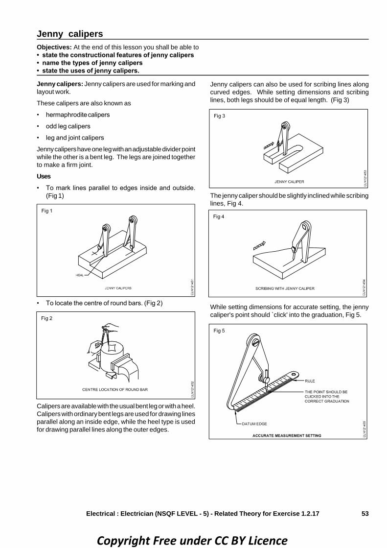
53
Jenny calipersObjectives: At the end of this lesson you shall be able to• state the constructional features of jenny calipers• name the types of jenny calipers• state the uses of jenny calipers.
Jenny calipers: Jenny calipers are used for marking andlayout work.
These calipers are also known as
• hermaphrodite calipers
• odd leg calipers
• leg and joint calipers
Jenny calipers have one leg with an adjustable divider pointwhile the other is a bent leg. The legs are joined togetherto make a firm joint.
Uses• To mark lines parallel to edges inside and outside.
(Fig 1)
• To locate the centre of round bars. (Fig 2)
Calipers are available with the usual bent leg or with a heel.Calipers with ordinary bent legs are used for drawing linesparallel along an inside edge, while the heel type is usedfor drawing parallel lines along the outer edges.
Jenny calipers can also be used for scribing lines alongcurved edges. While setting dimensions and scribinglines, both legs should be of equal length. (Fig 3)
Electrical : Electrician (NSQF LEVEL - 5) - Related Theory for Exercise 1.2.17
The jenny caliper should be slightly inclined while scribinglines, Fig 4.
While setting dimensions for accurate setting, the jennycaliper's point should ̀ click' into the graduation, Fig 5.
Copyright Free under CC BY Licence

54
• check the flatness of surfaces (Fig 3)
• mark lines at 90° to the edges of workpieces (Fig 4)
• set workpieces at right angles on work-holding devices.(Fig 5)
Length measurementObjectives: At the end of this lesson you shall be able to• name the base unit of length measurement as per SI (System of International)• state the multiples of metre and their values.
Length measurement SI units: When we measure anobject we are actually comparing it with a known standardof measurement.
The base unit of length as per SI is the metre.
Length: SI unit and multiples
Base unit: The base unit of length as per the SystemInternationale is the metre.
Metre (m) = 1000 mm
Centimetre (cm) = 10 mm
Millimetre (mm) = 0.001 m = 10-3 m
1 Micrometre μm = 10-6 m = 0.000001 m
1 Micrometer = 10-3 mm = 0.001 mm
Measurement in engineering practice: Usually, inengineering practice, the preferred unit of length measure-ment is the millimetre. Both large and small dimensionsare stated in millimetres.
The British system of length measurement: The othersystem of length measurement is the British system. Inthis system the base unit is the imperial standard yard.Most countries including Great Britain have, however,switched over to the SI units in recent years.
Try squareObjectives: At the end of this lesson you shall be able to• name the parts of a try square• state the uses of a try square.Try square: The try square is a precision instrument whichis used to check squareness (angles of 90°). The accuracyis about 0.002 mm per 10 mm length, which is accurateenough for most workshop purposes. The try square hasa blade with parallel surfaces. The blade is fixed in thestock at 90°. (Fig 1)
The try square is used to
• check the squareness of machined or filed surfaces.(Fig 2)
Electrical : Electrician (NSQF LEVEL - 5) - Related Theory for Exercise 1.2.17
Try squares are made of hardened steel.
Try sqaures are specified according to the length of theblade i.e. 100 mm, 150 mm, 200 mm.
Copyright Free under CC BY Licence

55
Scriber:A scriber is a sharp, pointed, steel tool made fromcarbon tool steel. There are two types of scribers.
• Double end and plain scribers (Fig 1)
Uses: Used for scribing lines on the metal being laid out.(Fig 2)
Divider: A divider consists of a pair of steel legs adjustedby a screw and nut, and held together by a circular springat one end. A handle is inserted on the spring.
Uses: A divider is used for
• measuring distances between points
• transferring measurements directly from a rule
• scribing circles and arcs on metals. (Fig 3)
Electrical : Electrician (NSQF LEVEL - 5) - Related Theory for Exercise 1.2.17
Scriber, dividerObjectives: At the end of this lesson you shall be able to• state the features of scribers and dividers• state the uses of scribers and dividers.
Radius gaugesObjectives: At the end of this lesson you shall be able to• state the uses of radius gauges• state the features of radius gauges.
Radius gauges: Radius gauges are used to check theinternal and external radius of workpieces.
These gauges are made of high quality steel sheets andare finished to accurate radius.
The radius of parts are checked by comparing the radiusof the gauges.
Radius gauges are available in sets of several blades heldin a holder. Each blade can be separately pulled out of theholder when in use.
The size of the radius is marked on individual blades of thegauges. (Fig 1)
Copyright Free under CC BY Licence

56
• Fixed Surface gauge (Fig 3)
• Universal Surface gauge(Fig 4)
The radius gauges are available in different combinations.
– Sets with internal and external radius.(Figs 2 & 3)
Universal surface gaugeObjectives: At the end of this lesson you shall be able to• state the constructional features of surface gauges• name the different types of surface gauges• state the uses of surface gauges• state the advantages of universal surface gauges.
Universal surface gauge : A surface gauge is one of themost common marking tools used for:
• scribing lines parallel to a datum surface (Fig 1)
• setting jobs on machines parallel to a datum surface(Fig 2)
Electrical : Electrician (NSQF LEVEL - 5) - Related Theory for Exercise 1.2.17
Before using radius gauges:
• ensure the gauges are perfectly clean
• remove burrs, if any, from the workpiece
• check and make sure there is no damage to the profileof the gauge.
– Individual gauges for each radius. (Fig 4)
• checking the height and parallelism of jobs
• setting jobs concentric to the machine spindle.
Types of surface gauges: A surface gauge/scribing blockis of two types.
Copyright Free under CC BY Licence

57
Surface gauge (fixed type): This consists of a heavy flatbase and a spindle, fixed upright to which a scriber isattached with a snug and a clamp nut.
Universal surface gauge: This has the following addi-tional features.
• The spindle can be set to any position.
• Fine adjustments can be made quickly.
• Can also be used on cylindrical surfaces.
• Parallel lines can be scribed from any datum edge withthe help of guide pins.(Fig 4)
Parts and functions of a universal surface gauge(Fig 5)
Base: The base is made of steel or cast iron with a ̀ Vee'groove at the bottom. The ̀ Vee' helps to seat on the circularwork. The guide pins fitted in the base are helpful forscribing lines from any datum edge.
Rocker arm: A rocker arm is attached to the base alongwith a spring and a fine adjustment screw. This is used forfine adjustments.
DatumObjectives: At the end of this lesson you shall be able to• state the need for datum while marking• name the different datum points, surfaces or lines• state the basis of determining the datum while marking.
Datum: The height of a person is measured from the flooron which he stands. The floor becomes the common basisfor measurement, i.e. it becomes the DATUM.
A datum is a reference surface, line or point and its purposeis to provide a common position from which measurementsmay be taken. The datum may be an edge or centre linedepending on the shape of the work. For positioning a point,two datum references are required. (Figs 1 and 2)
Electrical : Electrician (NSQF LEVEL - 5) - Related Theory for Exercise 1.2.17
Spindle: The spindle is attached to the rocker arm.
Scriber: The scriber can be clamped in any position on thespindle with the help of a snug and clamp nut.
Marking table, surface plate, angle, plate, vee blocks andparallel blocks - all these serve as datum references.(Figs 3 and 4)
The datum should be indicated in the drawing.
The same datum must be used for transferring dimensionsto the workpiece.
Copyright Free under CC BY Licence

58
Electrical Related Theory for Exercise 1.2.18 & 1.2.19Electrician - Workshop practice (Allied trade)
Carpenter tools - wood saws - planes - wooden jointsObjective : At the end of this lesson you shall be able to• state about the timber• state the grain direction of wood and the common defects in timber
Timber is a raw material used for manufacturing woodenarticles. Timber is a product of a tree.
Wood is made up of numerous tube like cells packedclosely together. During the growth of the tree, these cellsare positioned in a certain direction. The direction of thesecells is referred to as the ̀ grain'. The direction of the graincan be identified by the visible lines on the surface of thetimber.
Any operation performed in the grain direction is called anoperation ̀ along the grain'. (Fig 1)
Any operation performed at right angle to the grain directionis called ̀ across the grain'.
Any irregularity occuring in the timber is a defect in thetimber. These defects in the timber reduce its strength,durability and utility value.
Common defects in timber : A knot is caused due to thegrowth of branches on the tree. It appears on the surfaceof planks and on boards when the logs are sawn. (Fig 2)
The following defects are caused due to uneven shrinkage,improper seasoning and defective storage.
• Twisting (Fig 3a)
• Cupping (Fig 3b)
• Cracking (Fig 3c)
Shakes• Radial shake (Fig 4a)
• Star shake (Fig 4b)
• Cup shake (Fig 4c)
Avoid defective pieces while selecting timberto get better results.
Marking and measuring toolsObjectives : At the end of this lesson you shall be able to• name the marking and measuring tools and their functions• state the functions of straight edge, marking gauge and wooden folding ruleMarking and measuring tools are used in woodwork formarking, measuring and checking the work at variousstages.
Common marking tools• Wooden folding rule• Steel rule
Copyright Free under CC BY Licence

59
Wooden folding rule: A wooden folding rule is graduatedboth in centimetres and inches. The most commonly usedis the two feet, 4-fold wood rule which is shown in Fig 1.
It is used for taking linear measurements, to an accuracyof 1 mm or 1/16th of an inch.
Steel rule : It is graduated in centimetres/inches with theirsubdivisions. The reading accuracy is 0.5 mm.
Common marking toolsThey are:
• straight edge
• marking gauge
• try square.
Straight edge: It is made of steel with perfect straight andparallel edges. It is normally used for drawing straight lineson a job. It can also be used for testing flatness of a surfaceand straightness of an edge. (Fig 2)
Marking gauge: It is a marking tool,consisting of(1)stock,(2)stem ,(3)spur and (4) thumb (locking) screw asshown in Fig 3.
The stock can be adjusted over the stem to set the requireddistance between the spur and the face of the stock. Thethumb screw is tightened to retain the measurement. Thespur, a pointed steel, inscribes lines on the surface of thewood.
It is used for marking lines parallel to the face or edges.(Fig 4)
Try square : It is used for checking marking lines at rightangles. It is also used for checking right angles andflatness of surfaces.
The parts of a try square are shown in Fig 5. It is availablein different sizes, from 150 mm to 800 mm.
Remember: Keep these tools separately fromthe other tools to prevent damage.Avoid dropping or knocking them off theworkbench.
Electrical : Electrician (NSQF LEVEL - 5) - Related Theory for Exercise 1.2.18 & 1.2.19
Copyright Free under CC BY Licence

60
The malletObjectives: At the end of this lesson you shall be able to• state the constructional feature of mallet• state the use of mallets• state specification of mallets.
The mallets are made of hard wood and it is used in placeof hammer. But the difference is head only.
Mallet are used for driving wood chisels and for adjustingwooden planes. It is used for assembling and dismantlingwooden works and for adjusting stop dogs in the workbench.
The handle is made of beech or ash with straight grainedfibres. The head is made of hard wood with twisted fibres.This prevents splitting of the wood.
A special type of mallet is made of ‘Ligno stone’ which ismade of special wood that is treated with heat and highpressure.
Some mallets have removable handles (Fig 1) which canbe taken out of the head easily so that parts can be storedeasily. Fig 2.
handle is driven in from the top and is tapered in its width.Its head is either round or square. (Fig 3)
The mallet is held upside down and dropped once or twiceon the work bench, the head of the mallet will be tightenedon the handle.
The striking faces of mallet heads are so bevelled so thatthey can hit the chisel. For most purposes a head of 110mm long, 80mm wide and 60 mm thick is suitable. The
Carpenter’s hammerObjectives : At the end of this lesson you shall be able to• state the uses of an carpenter’s hammer• name the parts of a carpenter’s hammer and state their function• name the type of carpenter’s hammers with specification
A carpenter’s hammer is a hand tool used for strikingpurpose while
1 punching
2 striking
3 pulling
• The major parts of a hammer are a head and a handle
• The head is made of drop-forged carbon steel
• The wooden handle must be capable of absorbingshock.
Parts of hammer head (Fig 1)
Handle
Pein
Cheek
Eye hole
CheekThe cheek is the striking portion slight convexly is given toit to avoid digging of the edge.
Electrical : Electrician (NSQF LEVEL - 5) - Related Theory for Exercise 1.2.18 & 1.2.19
Copyright Free under CC BY Licence

61
Claw hammer (Fig 3)
It is made of cast steel and carries the striking face at oneend and the claw at the other. The face is used to drive thenail into the wood and other striking purposes and the clawis used for extracting the nails out of the wood. Its size isdesignated by its weight and it varies from 0.25kg to 0.75kg.
Ball pein hammer (Fig 4)
It is made of cast steel and weight of about 110 gm to 910grams. It is also called as engineers’ hammer. One sideof it is in the shape of ball and hence the name it is also usedfor riveting.
Pein (Fig 2)
The pein is the other end of the head.
It is used for shapping and forming. Work like Rivetting andbending the pein is of different shapes like (Fig 2)
1 Ball pein (hammer)
2 Cross pein (hammer)
3 Straight pein (hammer)
4 Claw (hammer)
5 Tacks (hammer)
Eye holeAn eye hole is meant for the handle. It is shaped to fit thehandle rigidly. The wedges fix the handle in the eye hole.
SpecificationCarpenter’s hammer’s are specified by their weight and theshape of the pein. Their weight varies from 125gms to1500gms.
Electrical : Electrician (NSQF LEVEL - 5) - Related Theory for Exercise 1.2.18 & 1.2.19
Copyright Free under CC BY Licence

62
Cross pein hammer (Fig 5)
The head part of this hammer is across the handle andhence the name. It is used for all light works.
Due to this magnetism nails and screws are taken easilyand is used to hammer or strike very thin nails. Some timesit is called as pin hammer. It is weight is 100gms.
Carpenters’ hammer (Fig 6)
The hammer head has a rectangular or oval hole which istapered on the inside. The shape of this hole offers a goodhold for the handle when wedged.
The handle must firmly be secured in the head to preventaccidents. The wedge is driven diagonally into the end ofthe handle. The wood splits and is pressed against theinner wall of the hole.
In carpenter shop it is called as warrington hammer. Toextend the iron frames, for bending and for other works it isused. Its weight varies from 220gms to 910gms.
Straight pein hammer (Fig 7)
The hammer head is straight to the hammer handle. Thebottom part of the head is large and tapering towards endside. It is used in rivetting and to extend metal frames. Itsweight is 110gm and varies up to 900gms.
Tacks hammer (Fig 8)
It is lesser in weight than all other hammers. The hammerhead is straightly fitted to the handle of hammer. It hasslight magnetic properties.
PrecautionMake sure the handle is properly fitted. Selecta hammer with correct weight suitable for thejob.Check the head and handle for any cracks.Ensure the face of the hammer is free from oiland grease.
Wood working sawsObjectives: At the end of this lesson you shall be able to• state the functions and use of a handsaw• distinguish between a tenon-saw and a handsaw• illustrate the setting of the teeth of a saw.• name the various holding tools and their application
Electrical : Electrician (NSQF LEVEL - 5) - Related Theory for Exercise 1.2.18 & 1.2.19
The saws are used to cut the timber to the required shapesand sizes.
The saws most commonly used by an electrician are:
• handsaw
• tenon-saw.
Copyright Free under CC BY Licence

63
Handsaw: Figure 1 shows the parts of a handsaw. Theyare the handle and the blade.
Handle: It is generally made of wood.
Blade: It is made of tempered steel having teeth on thelower edge. The best quality saws are made from springsteel which decreases in thickness slightly from the teethto the back.
The blade is about 66cm (26 inches) long, and normally has2 1/4 teeth per cm (6tpi). The number of teeth of a handsawvaries up to 4 teeth per cm (10tpi).
A saw blade with less number of teeth per inch has biggerteeth. Therefore, it is used for rough work as it cuts quickly.
Tenon-saw: The tenon-saw is intended for finer work andis manufactured with a thinner blade. It is used for generalbench work such as joint construction, where more accu-racy is needed.
This saw is also known as the back saw. (Fig 2)
The blade is stiffened with a brass or steel back. The bladeis about 30cm (12 inch) long. The number of teeth of atenon-saw is 12 to 14 per inch.
Tooth geometry: The angle between the trailing edge ofone tooth and the leading edge of another is constant atabout 60° - 63° on all styles of saws. The angle on theleading edge of the tooth varies according to the style ofsaw, and the purpose for which it is designed. (Fig 3)
The hand saw has a rake angle of 8° to 10°. The tenon-sawhas a rake angle of 25° to 30°.
Setting of teeth: The teeth are set using setters as shownin Fig 4. It helps to keep the blade free in the cut slit.
Sharpening the blunt teeth is done with a triangular file asshown in Fig 5.
Uses: This saw is used for cutting tenons, sawing sides oftrenches and for general bench work and for cutting in roundblocks and T.W. battens and T.W. boards for wiringpurposes.
Always use the right saw for the right job.Do not apply excessive force to the saw whilecutting as very little effort is required to operatea sharpened saw.
Electrical : Electrician (NSQF LEVEL - 5) - Related Theory for Exercise 1.2.18 & 1.2.19
Copyright Free under CC BY Licence

64
In woodwork various holding devices are used to holdthewhile performing different operations such as planing,chiselling, sawing and filing.
The common holding tools are:
• woodworker's vice/carpenter's vice.
• `G' clamp.
• bench hook.
Woodworker's vice (Fig 1): It is made of metal and isfitted to the workbench. It is available in various sizes.
It consists of two jaws - movable and fixed. The anticlock-wise rotation of the handle, attached to the spindle, causesthe movable jaw to open. The job is held between the twojaws by rotating the handle in the clockwise direction.
G Clamp (Fig 2): It is a metal clamp in the shape of theletter`G' used for holding the job to the bench, while sawingor chiselling. It is also used to hold small parts of a job forgluing.
Bench hook: It is also known as cutting board and madeof hardwood. (Fig 3) It is used to hold the job while sawingor chiselling and at the same time protecting the workbenchand surface from damages. (Fig 4)
Using a tenon-saw and a bench hook
• Position the bottom rail of the bench hook against theedge of the bench or hold it in the vice.
• Place the timber against the top rail of the hook, thecutting mark just clear of the edge.
• Grip the timber and the top rail together. Use the thumbto act as a guide for the saw at the start of the cut.
Keep your thumb clear off the saw teeth.
Electrical : Electrician (NSQF LEVEL - 5) - Related Theory for Exercise 1.2.18 & 1.2.19
Holding devices
Copyright Free under CC BY Licence

65
Bench planesObjectives: At the end of this lesson you shall be able to• state the different types of planes and their functions• state the purpose of setting the jack plane blade.• state the parts and function of a rebate plane
Planes are used for producing flat and smooth surfaces bytaking off thin shavings of wood. Different types of planesare used for this purpose.
Types of planesThe most commonly available types of planes are:
• jack plane (Fig 1a)
• smoothing plane (Fig 1b)
• rebate plane. (Fig 1c)
Jack plane: It is used for initial planing of timber to bringthe size nearer to the required measurements. Its mainparts are indicated in Fig 2.
These parts are made of different materials as listed below.
Body – iron
Handle – wood
Knob – wood
Cutting iron/blade – tungsten steel
All other parts – metal
The size of the plane commonly used by an electrician is350 mm long with a 50 mm blade.
Smoothing plane: It is used for finishing the job to therequired size, and for planing small wooden pieces/parts ofthe job. It is shorter in length as compared to the jackplane. (Fig 1b)
The parts of a smoothing plane are similar to those of thejack plane. (Fig 2)
Rebate plane: It is used for planing or finishing rebatesi.e. rectangular recesses cut along or across the edge. Itsmain parts are shown in Fig 3.
The width of the plane and blade is less as compared tothat of the jack plane.
Ensure that the blades are well sharpenedbefore use. Always use the approporiate typeof plane for a given job.
Electrical : Electrician (NSQF LEVEL - 5) - Related Theory for Exercise 1.2.18 & 1.2.19
Copyright Free under CC BY Licence

66
A rebate plane is used for planing and finishing the rebates.
Parts of a rebate planeA metal rebate plane: A metal rebate plane consistsof the following parts. (Fig 1)
A Body: Made of metal with its face perfectly flat.
B Handle: It is the integral part of the body.
C Blade: It is made of well tempered steel.
D Cap with thumb screw: It is made of metal and it holdsthe cutter in position.
E Depth gauge: It is made of metal attached to one sideof the plane, and it can be adjusted according to thedepth of the rebate.
Wooden rebate plane: It consists of the following parts.(Fig 2)
Body: made of wood and holds the other parts.
Blade: made of well tempered steel.
Wedge: made of wood to hold the blade in the body to aset position.
Be sure that the blade is sharp and it is setsquarely to its base before use.
Drill bits - Types and sizesObjectives: At the end of this lesson you shall be able to• state the different types of drill bits, and their uses• state the parts of a drill bit.• state the different types of nails, wood screws and their uses
For marking round holes in different types of materials,such as metal, wood, plastic etc. drills are used.
Types of drill bitsThe most common drill bits are (a) twist drill and (b) flat drill.
Twist drills may be:
• parallel shank
• taper shank drills. (Fig 1)
Parallel or straight shank drills are held in the drill chuck.(Fig 2a)
Taper shank drills are held in taper sockets in the drillingmachine. (Fig 2b)
Parts of a twist drill: A twist drill consists of a body, point,neck and shank. The point comprises the cutting ele-ments, while the body guides the drill in operation. (Fig 2c)
Electrical : Electrician (NSQF LEVEL - 5) - Related Theory for Exercise 1.2.18 & 1.2.19
Rebate plane - parts and their functions
Copyright Free under CC BY Licence

67
Parts of a flat drill: The flat drill consists of a head, neckand shank. It has a tapered shank. (Fig 3)
Flat drill is used for drilling shallow holes in heavy works.
Sizes of the drill bits: Drills are available in various sizes.The size of the drill is indicated on the plain portion of itsshank.
Parallel shank drills are available in small sizes up to 12mmdiameter.
Taper shank drills are available in sizes from 3mm to 50mmdia.
To protect the twist drill bits from damage,place them separately in small boxes/contain-ers. (Fig 4)
These chill bits are attached to either hand drilling machineor electric drilling machine to drill holes.
Both nails and screws are used as fasteners in woodwork.Nails are used for cheaper types of work, and screws areused for a better class of work where additional strengthand durability is a must.
Specification of nails: Nails are specified stating their
• length,
• type, and
• gauge number.
Length in the case of nail includes the head of the nail.(Fig 1)
`Type' includes shape of the head, cross-section, purpose,and the metal the nail is made of.
Gauge is indicated by a number in accordance with thestandard wire gauge, where higher gauge number indicatesa smaller diameter of nail and vice versa.
Types of nails: There are different types of nails made fordifferent purposes. Those that are generally used inelectrical work are:
• wire nail (Fig 1a)
• wire clout nail (Fig 1b)
• cut tack or stud (Fig 1c)
• wire tack. (Fig 1d)
Specification of screws: Screws also are specified in asimilar way as nails are i.e. stating their length, designationnumber, type and the metal they are made of.
Parts of a wood screw: The parts of a wood screw areshown in Fig 2.
Electrical : Electrician (NSQF LEVEL - 5) - Related Theory for Exercise 1.2.18 & 1.2.19
Types of nails and wood screws
Copyright Free under CC BY Licence

68
Head : Uppermost part
Shank : Plain or unthreaded portion of 1/3 of thelength of the screw.
Pitch : It is the distance between adjacent threads
Point : The sharp edge of the screw end.
Thread : A special ridge around the core.
Length is measured from the point of the screw to theportion it can enter the timber. (Fig 3)
The designation number of a screw indicates the diameterof the unthreaded shank. The screw number and thecorresponding diameter of the shank are given in IS 6739,6736 and 6760. The screw number is the screw designation.It is different from the SWG of wire nails. (Fig 4)
Types of screwsAccording to the shape of the head, screws are classifiedinto:
• slotted countersunk (flat) head wood screw(Fig 3a)- used for general purpose (IS:6760-1972)
• slotted countersunk raised head wood screw(Fig 3b)- used for fixing thick sheets to woods (IS:6736-1972)
• slotted round head screw (Fig 3c)- It is used for fixing thin sheets to woodwork. (IS:6739-
1972)
• coach or square head screw (Fig 3d)- is used for heavy duty work. It is tightened using
spanner.
Availability: Wood screws are generally made of mildsteel, aluminium and brass, and are from 8 mm to 200 mmlength, with the screw numbers ranging from 0 to 24.
The chart of preferred lengths and screw numbercombinations for wood screws is available in the relevantIS.
The screws commonly used by electricians are from screwNo. 4 to 12 and 12 mm to 50 mm in length.
Wood screws are available in packets of 100 and 200numbers. The size and number of the screw are indicatedon the packet.
Mild steel screws are most commonly used for generalwork. Brass and aluminium screws are used to match themetal fitting and also to prevent rust under damp conditions.
Ratchet braceObjective: At the end of this lesson you shall be able to• name the parts of a ratchet brace and state their functions.• state the countersunk bits sizes
One of the tools for holding various types of bits for makingholes of various diameters in wood by manual operation isthe ratchet brace.
It is used for jobs that require slow speed and high torqueoperation.
Parts and their functions (Fig 1)
Head: The head is made of wood and is fitted to the upperend of the crank with ball bearings. It is used to hold thebrace in an upright position by one hand, and also apply therequired force during operation.
Crank: It is a metal rod bent to the form shown in Fig 1.
Ratchet braces with different sweep sizes of crank areavailable. The size mostly used is one of 250mm sweep.A wooden handle is provided to rotate the crank by the handthat is free.
Chuck: It is fitted at the lower end of the crank. It has twojaws for holding square shank bits, and a shell for tighteningand slackening jaws.
Ratchet: It permits the chuck to rotate in only one selecteddirection. The selection of direction is done by turning thecam ring. This allows to rotate the bit continuously, and inconfined spaces as well where the full sweep of the crankis restricted. (Fig 1)
Electrical : Electrician (NSQF LEVEL - 5) - Related Theory for Exercise 1.2.18 & 1.2.19
Copyright Free under CC BY Licence

69
Countersunking is done on a drilled screw hole to accom-modate the countersunk head of the wood screw. Theprocess of removing out material round a hole at its surfaceup to a depth to match the CS screw head is known ascountersinking. (Fig 1)
Variation of the size of head CS screws with the screwnumber makes it necessary to select the suitable CS bit.
Sizes of countersunk bits: The countersunk bit size isspecified by the rim diameter.
The general size of the bit varies from 10 mm to 25 mm.
The 82o cutting angle CS bits are used because woodscrews always bear 90o slope.
Method of selection: Select the countersunk bit of thenext higher dia. size to that of the wood screws headdiameter. With the head of screw ensure the required depthwhile countersunking. (Fig 2)
Types: The two types of bits are:
• Rose countersunk bit (Fig 3a) which is a multi-cuttingedge tool
• Nail countersunk bit (Fig 3b) which has a single-cuttingedge.
Electrical : Electrician (NSQF LEVEL - 5) - Related Theory for Exercise 1.2.18 & 1.2.19
Countersunk bits - types - sizes
Copyright Free under CC BY Licence

70
Screwdrivers used in woodworkObjective: At the end of this lesson you shall be able to• name the various types of screwdrivers, and state their sizes and uses.
Screwdrivers are available in different sizes and patternsaccording to their application.
Types of screwdrivers: London pattern is a heavyscrewdriver having a size of 75 to 350mm with a flat shank.It is used for general woodwork. (Fig 1a)
Cabinet pattern is a medium screwdriver having a size of75 to 350mm. It is used for cabinet works. (Fig 1b)
Electrician pattern is a common type of screwdriver usedby electricians. It is available from 100mm to 300mm size.The handle is made of either wood or plastic. The shank iseither insulated or non-insulated. (Fig 1c)
In the ratchet type of a screwdriver, a ratchet is fittedwithin the handle. The blade of the screwdriver can be setto different positions i.e for clockwise or anti-clockwiserevolution of the screwdriver blade. It can also be set to aneutral position (locked). It is used for general purposesand is available in sizes ranging from 50mm to 200mm.(Fig 1d)
A cranked screwdriver is a special type used wherenormal screwdrivers cannot be applied. (Fig 1e)
A spiral ratchet works on rotary action. It is used withinterchangeable blades of different sizes and patternsavailable in 300, 500, 600mm length. Only downwardpressure need be applied while using this type ofscrewdrivers. This type of screwdriver can also be set inboth clock and anticlockwise revolution for screwing andunscrewing purposes. (Fig 1f)
A Phillips screwdriver is used to drive Phillips headscrews. It is a special purpose screwdriver available in 75to 200mm sizes. The Phillips screwdriver (Fig 2) will notslip and burr the head of the screw if a proper size isselected.
Sharpening and setting of saw teethObjective: At the end of this lesson you shall be able to• describe the steps involved in `sharpening and setting' of the saw teeth• explain the methods of re-sharpening jack plane blade
To perform the sawing operations with ease and accuracy,the saw must be in good condition with its teeth sharpenedand well set.Sharpening of a saw involves 4 steps which are as follows.
Topping or jointing: This is done to bring down the pointsof all the teeth to the same level. A flat file is held in awooden block and rubbed over the teeth until the lowesttooth touches the file face. (Fig 1)
Reshaping: It is necessary to restore the tips of the teeth.Therefore the gullet of each tooth is filed down using asuitable size triangular file. Care is taken to maintain auniform depth of gullets, pitch and angles of teeth. (Fig 2)
Setting: Setting is a process of bending every alternatetooth to the opposite direction. This is carried out by usinga saw-set pliers. (Fig 3)
Electrical : Electrician (NSQF LEVEL - 5) - Related Theory for Exercise 1.2.18 & 1.2.19
Copyright Free under CC BY Licence
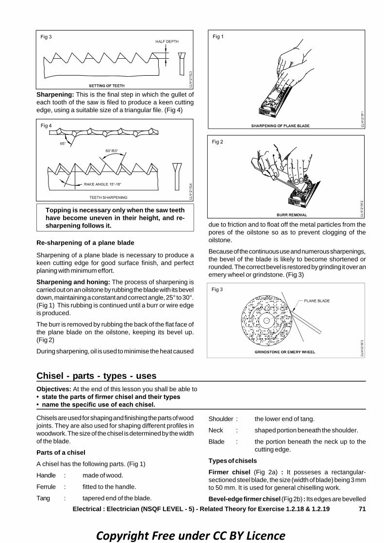
71
Sharpening: This is the final step in which the gullet ofeach tooth of the saw is filed to produce a keen cuttingedge, using a suitable size of a triangular file. (Fig 4)
Topping is necessary only when the saw teethhave become uneven in their height, and re-sharpening follows it.
Re-sharpening of a plane blade
Sharpening of a plane blade is necessary to produce akeen cutting edge for good surface finish, and perfectplaning with minimum effort.
Sharpening and honing: The process of sharpening iscarried out on an oilstone by rubbing the blade with its beveldown, maintaining a constant and correct angle, 25° to 30°.(Fig 1) This rubbing is continued until a burr or wire edgeis produced.
The burr is removed by rubbing the back of the flat face ofthe plane blade on the oilstone, keeping its bevel up.(Fig 2)
During sharpening, oil is used to minimise the heat caused
Electrical : Electrician (NSQF LEVEL - 5) - Related Theory for Exercise 1.2.18 & 1.2.19
due to friction and to float off the metal particles from thepores of the oilstone so as to prevent clogging of theoilstone.
Because of the continuous use and numerous sharpenings,the bevel of the blade is likely to become shortened orrounded. The correct bevel is restored by grinding it over anemery wheel or grindstone. (Fig 3)
Chisel - parts - types - usesObjectives: At the end of this lesson you shall be able to• state the parts of firmer chisel and their types• name the specific use of each chisel.
Chisels are used for shaping and finishing the parts of woodjoints. They are also used for shaping different profiles inwoodwork. The size of the chisel is determined by the widthof the blade.
Parts of a chiselA chisel has the following parts. (Fig 1)
Handle : made of wood.
Ferrule : fitted to the handle.
Tang : tapered end of the blade.
Shoulder : the lower end of tang.
Neck : shaped portion beneath the shoulder.
Blade : the portion beneath the neck up to thecutting edge.
Types of chiselsFirmer chisel (Fig 2a) : It posseses a rectangular-sectioned steel blade, the size (width of blade) being 3 mmto 50 mm. It is used for general chiselling work.
Bevel-edge firmer chisel (Fig 2b) : Its edges are bevelled
Copyright Free under CC BY Licence

72
Curve-cutting saws - types - usesObjectives: At the end of this lesson you shall be able to• state the necessity of curve-cutting saws• state the types of curve-cutting saws and their application.
along the length. It is used for light chiselling and to cleansharp corners where the edges of a normal firmer chiselmay not reach.
Half- lap joints - types - usesObjectives: At the end of this lesson you shall be able to• state the necessity of lap joints• state the types of lap joints.
Electrical : Electrician (NSQF LEVEL - 5) - Related Theory for Exercise 1.2.18 & 1.2.19
Necessity of lap Joint:Half-lap joints are employed in frame construction wheretwo parts of a job meet either near the ends or at a distance.To keep them flush, laps are made equal to half thethickness in each part. These joints are strengthened byfixing screws.
Types of half-lap jointsEnd-lap joint (Fig 1): This joint is used where two parts ofa job cross each other at the ends, say at the corners.
Paring chisel (Fig 2c) : It has an extra long, thin blade withthe edges bevelled. It is used for paring and finishing joints.
Mortise chisel (Fig 2d) : It posseses a stronger, square-sectional blade.It is used for mortising i.e. makingrectangular holes in wood.
Middle-lap joint (Fig 2): This joint is used where one partof a job meets another part at some distance from the ends.
Cross-lap joint (Fig 3): This joint is used where two partsof a frame cross each other at a distance from the ends.
Curve-cutting saws have narrow blades which enable themto turn along the curve with ease while sawing along the
curves. Stiff and wider blades are provided with handles,while very fine blades are held in frames to keep them under
Copyright Free under CC BY Licence

73
tension. Very narrow, fine blades are dispensed with andreplaced as soon as they become blunt. The other bladesare re-sharpened.
There are various types of curve-cutting saws. The saws,with slightly wider blades are used for cutting larger curves,and the saws with finer blades are used for cutting sharpcurves.
Types of curve-cutting saws• Compass saw (Fig 1): Used for larger curve cutting.
• Keyhole saw or pad saw (Fig 2): It is used for internalcutting.
• Coping saw: It is used for cutting sharp corners.(Fig 3)
– Fretsaw: It has a very fine blade. (Fig 4) It is used forcutting sharp and fine curves.
Blades with larger teeth will cut faster, but thesurface will be rough and the blades withsmaller teeth will cut slower, but the surfacewill have a fine finish.
Electrical : Electrician (NSQF LEVEL - 5) - Related Theory for Exercise 1.2.18 & 1.2.19
Wood working files - parts - usesObjectives : At the end of this lesson you shall be able to• state the use of wood working files• state the types of wood working files and their application.
Wood working files are used to shape various profiles forsmooth finish in wood or laminates.
Types and uses of wood working files : Various typesof the available wood working files are named according tothe shape of their cross-section. (Fig 1)
Round files: Used for finishing concave corners, and forfinishing and enlarging.
Flat files: Used for finishing end grains and corner edges.
Half-round files: Used for finishing both corner and convexedges.
Wood rasp files: Used for preliminary rough work for rapidremoval of waste part of the wood.
All files should be cleaned frequently. (Fig 2)
Copyright Free under CC BY Licence

74
Electrical Related Theory for Exercise 1.2.20 & 1.2.23Electrician - Workshop practice (Allied trade)
Sheet metal - marking and cutting tools - rivet jointsObjectives : At the end of this lesson you shall be able to• state the six types of metal sheets used in sheet metal work• state how the plate and the sheet are differentiated from each other.• state the different types of snips and their uses• state the uses of solid cold punches• state the uses of self tapping screwA large quantity of sheet metal used in the sheet metalindustry is steel, rolled into sheets of various thicknessesand coated with zinc, tin or other metals. Other than steel,the worker uses sheets made out of zinc, copper, aluminium,stainless steel etc.
The term `sheet metal' generally applies to metals andalloys in sheets rolled into various thicknesses less than5mm. Sheets over 5 mm thick are called plates.
Earlier, the sheets were specified by standard wire gaugenumbers. Each gauge is designated with a definite thickness.(Table 1) The larger the gauge number, the lesser thethickness. Now the sheet thickness is specified in mm,say 0.40, 0.50, 0.63, 0.80, 0.90, 1.00, 1.12, 1.25 etc.
Sheet thicknessGauge No. Inch mm
18 0.048 1.22
19 0.040 1.02
20 0.036 0.91
21 0.032 0.81
22 0.028 0.71
23 0.024 0.61
24 0.022 0.56
25 0.020 0.5127 0.0164 0.4228 0.0148 0.38
Types of sheetsSheet steel: It is an uncoated sheet with bluish-blackappearance. The use of this metal is limited to articles thatare to be painted or enamelled.
Galvanised iron sheet: The zinc-coated iron sheet isknown as galvanised iron sheet, popularly known as GIsheet. The zinc coating resists rust. Articles like pans,buckets, furnaces, cabinets are made with GI sheet.
Copper sheets: Copper sheets are available either ascold-rolled or hot-rolled sheets. Cold-rolled sheets areworked easily in sheet metal shops. Gutters, roof flashingand hoods are common examples where copper sheet isused.
Aluminium sheets: Aluminium sheets are highly resistiveto corrosion, whitish in colour and light in weight. They arewidely used in the manufacture of a number of articles suchas household utensils, lighting fixtures, windows etc.
Tin plates: Tin plate is sheet iron coated with tin to protectthe iron sheet against rust. The size and thickness of thetin plate are denoted by special marks, not by gaugenumbers.
Tin plates are used for food containers, dairy equipment,furnace fittings etc.
Brass sheet: Brass is an alloy of copper and zinc in variousproportions. It will not corrode and is extensively used incraft.
Snips
A snip is a cutting tool and is used for cutting thin sheetsof metal.
There are two types of snips.
• Straight snips
• Bent snips
Parts of a straight snip (Fig 1)
• Handle (1)
• Blade (2)
• Stops (3)
Table - 1
Copyright Free under CC BY Licence

75
Bent snip: Bent snips have curved blades used for cuttinginternal curves. For trimming a cylinder keep the lowerblade on the outside of cut. (Fig 3)
Solid cold punchesFor making holes in sheet metal, cold punches can beutilized.
There are two types of cold punches used on sheet metal.
• Solid cold punch
• Hollow cold punch
In this lesson you will know about solid cold punches.
Solid cold punch: It is used to punch small holes in sheetmetal (thin gauge).
Generally small holes can be made by this punch. (Fig 1)
Precautions to be observed while using a solid coldpunch: The sheet should be kept on lead cake or on ahardwood block while punching (Fig 2).
While striking, watch the cutting point, not the head of thepunch.Hold the punch in a vertical positon on the correctlocations.
Self-tapping screwsSelf-tapping screws are used in assembly where thinsection metal sheets are used. Joints made using thesescrews are vibration-resistant, and can be assembled anddismantled many times. The three types of self-tappingscrews are:
Straight snips: A straight snip has straight blades forstraight line cutting. It can also be used for external curvedcuts.(Fig 2)
• thread forming (Fig 1a)
• thread cutting (Fig 1b)
• self-piercing. (Fig 1c)
Electrical : Electrician (NSQF LEVEL - 5) - Related Theory for Exercise 1.2.18 & 1.2.19
Copyright Free under CC BY Licence
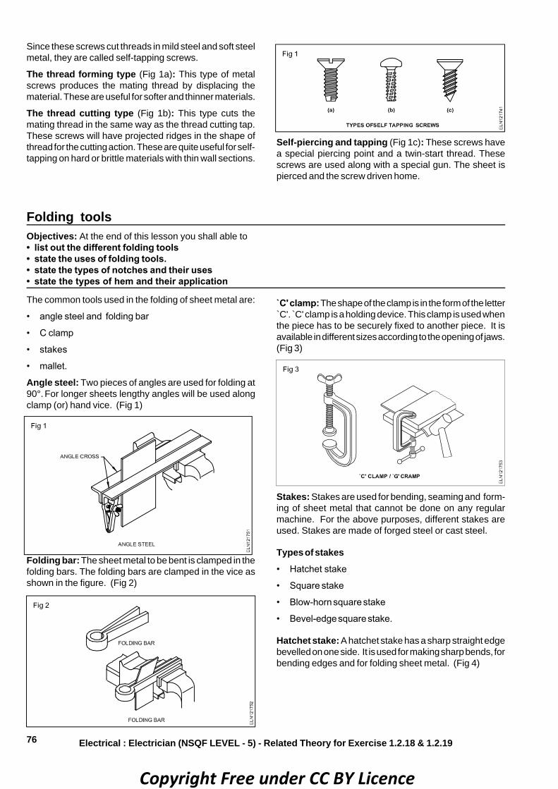
76
Since these screws cut threads in mild steel and soft steelmetal, they are called self-tapping screws.
The thread forming type (Fig 1a): This type of metalscrews produces the mating thread by displacing thematerial. These are useful for softer and thinner materials.
The thread cutting type (Fig 1b): This type cuts themating thread in the same way as the thread cutting tap.These screws will have projected ridges in the shape ofthread for the cutting action. These are quite useful for self-tapping on hard or brittle materials with thin wall sections.
Self-piercing and tapping (Fig 1c): These screws havea special piercing point and a twin-start thread. Thesescrews are used along with a special gun. The sheet ispierced and the screw driven home.
Folding toolsObjectives: At the end of this lesson you shall able to• list out the different folding tools• state the uses of folding tools.• state the types of notches and their uses• state the types of hem and their application
Folding bar: The sheet metal to be bent is clamped in thefolding bars. The folding bars are clamped in the vice asshown in the figure. (Fig 2)
`C' clamp: The shape of the clamp is in the form of the letter`C'. ̀ C' clamp is a holding device. This clamp is used whenthe piece has to be securely fixed to another piece. It isavailable in different sizes according to the opening of jaws.(Fig 3)
Stakes: Stakes are used for bending, seaming and form-ing of sheet metal that cannot be done on any regularmachine. For the above purposes, different stakes areused. Stakes are made of forged steel or cast steel.
Types of stakes• Hatchet stake
• Square stake
• Blow-horn square stake
• Bevel-edge square stake.
Hatchet stake: A hatchet stake has a sharp straight edgebevelled on one side. It is used for making sharp bends, forbending edges and for folding sheet metal. (Fig 4)
Electrical : Electrician (NSQF LEVEL - 5) - Related Theory for Exercise 1.2.18 & 1.2.19
The common tools used in the folding of sheet metal are:
• angle steel and folding bar
• C clamp
• stakes
• mallet.
Angle steel: Two pieces of angles are used for folding at90°. For longer sheets lengthy angles will be used alongclamp (or) hand vice. (Fig 1)
Copyright Free under CC BY Licence

77
NotchesNotches: Notches are the spaces provided for joining theedges when sheet metals are cut from the layout. (Fig 1) Purpose of notches
• To prevent excess material from overlapping and causinga bulge at the seam and edges.
• To allow the work to be formed to the required size andshape.
Types of notches: A straight notch or slit is a straight cutmade in the edge of the sheet where it is to be bent.(Fig 2)
Square stake: A square stake has a flat and square-shaped head with a long shank. It is used for generalpurposes. (Fig 5)
Bevel-edged square stake: A bevel-edged square stakeis used to form corners and edges.(Fig 7)
Electrical : Electrician (NSQF LEVEL - 5) - Related Theory for Exercise 1.2.20 & 1.2.23
Blow-horn stake: It has a short tapered horn at one end,and a long tapered one at the other end. It is used informing, riveting or seaming tapered, cone-shaped articles,such as funnels etc. (Fig 6)
Mallet: A mallet is used for working on sheet metal. It willnot damage the sheet surface while working. Mallets aremade of wood, rubber, copper etc.(Fig 8)
Copyright Free under CC BY Licence
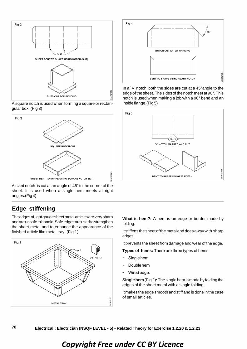
78
A square notch is used when forming a square or rectan-gular box. (Fig 3)
Electrical : Electrician (NSQF LEVEL - 5) - Related Theory for Exercise 1.2.20 & 1.2.23
A slant notch is cut at an angle of 45° to the corner of thesheet. It is used when a single hem meets at rightangles.(Fig 4)
In a ̀ V' notch both the sides are cut at a 45°angle to theedge of the sheet. The sides of the notch meet at 90°. Thisnotch is used when making a job with a 90° bend and aninside flange.(Fig 5)
Edge stiffeningThe edges of light gauge sheet metal articles are very sharpand are unsafe to handle. Safe edges are used to strengthenthe sheet metal and to enhance the appearance of thefinished article like metal tray. (Fig 1)
What is hem?: A hem is an edge or border made byfolding.
It stiffens the sheet of the metal and does away with sharpedges.
It prevents the sheet from damage and wear of the edge.
Types of hems: There are three types of hems.
• Single hem
• Double hem
• Wired edge.
Single hem (Fig 2): The single hem is made by folding theedges of the sheet metal with a single folding.
It makes the edge smooth and stiff and is done in the caseof small articles.
Copyright Free under CC BY Licence

79
Pattern developmentObjectives: At the end of this lesson you shall able to• state about pattern development• state the different types of pattern development.
Before starting on any project in sheet metal, a patternshould be developed for the accuracy of the finishedarticles.
The pattern is nothing but a flat outline of the job. Most ofthe patterns are obtained from development of surfaces ofsome common geometrical solids such as cylinder, cone,prism, pyramid etc.
The pattern or outline of an object may be drawn on paper.Then it can be transfered to the sheet metal or it can bedirectly developed on the sheet and cut from the metal.
Generally there are three methods of development ofpatterns.
• Parallel line development
• Radial line development
• Triangulation
Methods of pattern development
There are three methods in general use.
The class of geometrical form of the object to be made mustbe taken into account when deciding on which method isto be used.
Parallel line method (Fig 1): This method is used todevelop patterns for shapes like boxes, prisms andcylinders.
Radial line method (Fig 2): Objects like pyramids andcones can be developed using this method. These includeall shapes which form parts of pyramids or cones.
All lines radiate from the apex.
Electrical : Electrician (NSQF LEVEL - 5) - Related Theory for Exercise 1.2.20 & 1.2.23
Double hem (Fig 3): A double hem is made by folding theedges over twice to make it smooth, and this is donenormally to strengthen the edges of lengthy articles.
Triangulation (Fig 3): This method is used to developpatterns for shapes having no apex and in which not allsides are parallel, i.e. Class 3.
While both the radial and parallel line methodscannot be applied to shapes shown in Fig 3, themethod of triangulation can be used in thedevelopment of patterns for shapes depicted inFig 1 and Fig 2.
Copyright Free under CC BY Licence

80 Electrical : Electrician (NSQF LEVEL - 5) - Related Theory for Exercise 1.2.20 & 1.2.23
RivetsObjectives : At the end of this lesson you shall be able to• define riveting and state their uses• list out the different types of rivets and which materials the rivets are made.
Riveting: Riveting is one of the satisfactory methods ofmaking permanent joints of two pieces - metal snips.(Fig 1)
It is customary to use rivets of the same metal as that ofthe parts that are being joined.
Uses: Rivets are used for joining metal sheets and platesin fabrication work, such as bridges, ships, cranes, struc-tural steel work, boilers, aircraft and in various other works.
Material: In riveting, the rivets are secured by deformingthe shank to form the head. These are made of ductilematerials like low carbon steel, brass, copper and alu-minium.
Types of rivets (Fig 2)
The four most common types of rivets are:
• tinmen's rivet
• flat head rivet
• round head rivet
• countersunk head rivet.
Each rivet consists of a head and a cylindrical body calledas shank. (Fig 3)
Sizes of rivets: Sizes of rivets are determined by thediameter and length of the shank.
Selection of rivet size: The diameter of the rivet iscalculated by using the formula
Tx3to
2
12D �
��
���
� where T is total thickness.
Copyright Free under CC BY Licence

81Electrical : Electrician (NSQF LEVEL - 5) - Related Theory for Exercise 1.2.20 & 1.2.23
The shank length is given by
���
���� D
21
12TL
where ̀ T' is the sheet thickness and ̀ D' is the diameter ofthe rivet.
Normally tinmen's rivets are designated by numbers.
The dimension of the tinmen's rivets is given below. (Fig 4)
Method of riveting: Riveting may be done by hand or bymachine.
While riveting by hand, it can be done with a hammer anda rivet set.
Rivet set: A cross-section of a rivet set is shown in thefigure 5a, b and c. The shallow, cup-shaped hole is usedto draw the sheet and the rivet together. The outlet on theside allows the slug to drop out.
The cup shape is used for forming the rivet head.
The rivet set selected should have a hole slightly larger thanthe diameter of the rivet.
Spacing of rivets: The space or distance from the edge ofthe metal to the centre of any rivet should be atleast twicethe diameter of the rivet to avoid tearing. The ̀ Lap' distance(4D) is shown in Fig 6.
The minimum distance between the rivets (pitch) should besufficient to allow the rivets to be driven without interference.The distance should be atleast three times the thicknessof the sheet or above.
The maximum distance should never exceed 24 times thethickness of the sheet. Otherwise buckling will take placeas shown in Fig 7.
Copyright Free under CC BY Licence

82
Electrical Related Theory for Exercise 1.2.21 & 1.2.22Electrician - Workshop practice (Allied trade)
Drills and drilling machines - Internal and external threadsObjectives : At the end of this lesson you shall be able to• state the functions of drills• name the parts of a drill• name the drill bit holders• state the uses of countersunking bits
Drill: Drilling is a process of making holes on workpiecesby using a drill.
Parts of a drill (Fig 1)
Body: The body is the portion between the point andshank.
Flutes: Flutes are the spiral grooves which run to the lengthof the drill.
The flutes help:
• to form the cutting edges
• to curl the chips and allow them to come out (Fig 4)
• the coolant to flow to the cutting edge.
• Tang (1)
• Shank (2)
• Body (3)
• Flute (4)
• Land (5)
• Point angle (6)
• Cutting lip (7)
• Chisel edge (8)
Tang: Tang is the part that fits into the slot of the drillingmachine spindle.
Shank: This is the driving end of the drill which is fitted onthe machine. Shanks are of two types.
• Taper shank: for larger diameter drills.
• Straight shank: for smaller diameter drills.
The shank may be parallel or tapered.(Figs 2 and 3) Drillswith parallel or straight shanks are made in small sizes, upto 12mm (1/2 in) diameter and the shank has the samediameter as the flutes.
Taper shank drills are made in sizes from 3mm (1/8 in)diameter up to 50mm (2 in) diameter.
Copyright Free under CC BY Licence

83
Land/margin: Land/margin is the narrow strip whichextends to the entire length of the flutes. The diameter ofthe drill is measured across the land/margin.
Body clearance: Body clearance is the part of the bodywhich is reduced in diameter to cut down the frictionbetween the drill and the hole being drilled.
Web:Web is the metal column which separates the flutes.It gradually increases in thickness towards the shank.
Drill bit holderDrill chuck: Drill chuck is attached to the main spindle forstraight shank basis. (Fig 5)
Sleeve: This is used to match bit tapers and the spindletaper holes. (Fig 6)
Socket: This is used when the main spindle length is tooshort, and the bit is changed frequently. (Fig 7)
Taper shank drills are held in taper sockets in themachine.(Fig 8)
The tang on a taper shank drill enables easy removal of thedrill from the socket at the end of the drilling work. This isdone using a drift. (Fig 9) The tang also serves to preventthe drill from rotating in the socket.
Use of a coolant: A coolant is used to cool the cuttingtool and the job.
Electrical : Electrician (NSQF LEVEL - 5) - Related Theory for Exercise 1.2.21 & 1.2.22
Drilling machinesObjectives: At the end of this lesson you shall be able to• state the types of hand drilling machines and their uses• state the parts of bench and pillar drilling machine• explain the features of machine vice
Making holes in sheet metal by using solid punches is aslow and inefficient process.
It is necessary to drill holes when working with heavymaterial.
The holes can be drilled by hand or by machine. Whendrilling by hand, a hand drilling machine (Fig 1) or theelectric hand drilling machine (Fig 2) is used.
Twist drills are used as a cutting tool for drilling holes. Thehand drill is used for drilling holes up to 6.5 mm diameter.
The portable electric hand drilling machine is a very popularand useful power tool. It comes in different sizes andcapacities.
The handle shown in Fig 2 is called a pistol grip handle.
Copyright Free under CC BY Licence

84
The parts of an electric hand machine are shown in Fig 2.
Electrical : Electrician (NSQF LEVEL - 5) - Related Theory for Exercise 1.2.21 & 1.2.22
Precautions to be observed : Make sure the holes areproperly located and punched with a centre punch.
Check the drill size. If the markings on the drill are not clear,use a drill gauge.
Be sure the drill is properly centred in the chuck by turning(rotating).
Be sure the work is mounted properly in a holding devicesuch as a vice or `G' clamp.
Check the centering of the drill after the point has juststarted in the metal. Relocate the hole with a centre punch,if necessary. Feed the drill with a light, even pressure.
Types of Electric Drilling Machines: Some of the electricdrilling machines are listed here.
• The sensitive bench dilling mchine
• The pillar drilling machine
• The radial arm drilling machine. (Radial drilling ma-chine)
(As you are not likely to use the column and radial type ofdrilling machines now, only the sensitive and pillar typemachines are explained here.)
Sensitive bench driling machine: The simplest type ofsensitive bench drilling machine is shown in the (figure 3)with its various parts marked. This machine is used for lightduty work. (Fig 3)
This machine is capable of drilling holes up to 12.5mmdiameter. The drills are fitted in the chuck or directly in thetapered hole of the machine spindle.
Different spindle speeds are achieved by changing the beltposition in the stepped pulley (Fig 4).
For normal drilling, the work surface is kept horizontal. If theholes are to be drilled at an angle, the table can be tilted.
The pillar drilling machine: This is an enlarged versionof the sensitive bench drilling machine. These drillingmachines are mounted on the floor and are driven by morepowerful electric motors. They are used for heavy dutywork. Pillar drilling machines are available in different
Copyright Free under CC BY Licence

85
sizes. Large machines are provided with a rack and pinionmechanism for moving the table for setting the work.
The machine vice: Most of the drilling works can be heldin a vice. Ensure that the drill does not drill through the viceafter it has passed through the work. For this purpose, thework can be lifted up and secured on parallel blocks,providing a gap between the work and the bottom of thevice. (Fig 6) Workpieces which are not accurate may besupported by wooden pieces. (Fig 5)
Electrical : Electrician (NSQF LEVEL - 5) - Related Theory for Exercise 1.2.21 & 1.2.22
Parallels: The workpiece can be set on parallels to raiseit off the reference surface, and still maintain parallelism.Parallels are made in pairs to precisely the samedimensions, from hardened steel, finish-ground, with theopposite faces parallel and adjacent faces square. Avariety of sizes is available.
Cutting speed and RPM (Revolutions Per Minute)Objectives : At the end of this lesson you shall be able to• define cutting speed and rpm• state the factors for determining cutting speed• determine rpm/spindle speed
Cutting speed and r.p.m.: For a drill to give satisfactoryperformance, it must operate at the correct cutting speedand feed.
Cutting speed is the speed at which the cutting edgepasses over the material while cutting, and is expressed inmetres per minute.
Cutting speed is also sometimes stated as surface speedor peripheral speed.
Selection of the correct cutting speed for drilling dependson the materials to be drilled and the tool material. Therecommended cutting speeds for different materials aregiven in the table. Based on the cutting speed recom-mended, the r.p.m. at which a drill has to be driven isdetermined.
Materials being drilled Cutting speed m/min.
001 - 07muinimulA
05 - 53ssarB
53 - 02eznorB
Cast iron (grey) 25 - 40
54 - 53reppoC
04 - 03)dlim( leetS
Steel (medium carbon) 20 - 30
Steel (alloy-high tensile) 5 - 8
Thermo-setting plastic(Low speed due toabrasive properties.) 20 - 30
RPMThe r.p.m. will differ according to the diameter of the drills.The cutting speed being the same, larger diameter drills willhave lesser r.p.m., and smaller diameter drills will have ahigher r.p.m.
Calculating r.p.m.
CS =1000
dNπ
N =d
CS x 1000π
N = r.p.m.
CS = Cutting speed m / min
d = dia of drill in mm; π = 3.14
ExampleCalculate the spindle speed (r.p.m.) for a high speed steeldrill of 24mm dia. to cut mild steel.
N =24 x 3.1430 x 1000 = 398 r.p.m.
The spindle speed is 400 r.p.m.
Feed of drill = Penetration of drill in a job perrevolution of drill.
Angle of chiselsObjectives : At the end of this lesson you shall be able to• state the point angles of chisels for different materials• state the different cutting angles of a chisel• state the effect of rake and clearance angles.
Point angles and materialsThe coreect point/ cutting angles (b) of the chisel depends
on the materials to be chipped. sharp angles are given forsoft materials and wide angles for hard materials.
Copyright Free under CC BY Licence

86
The correct point angle and angle of inclination generatethe correct rake and clearance angles. (Fig 1)
Table Material to Point Angle of be cut angle inclinationHigh carbonSteel 65° 39.5°
Cast iron 60° 37°
Midld steel 55° 34.5°
Brass 50° 32°
Copper 45° 29.5°
Aluminium 30° 22°
Vee threads - Tap and die setObjectives : At the end of this lesson you shall be able to• state the types of threads• describe the designation of ISO threads.• state pipe thread, parallel female thread and tappered thread
Electrical : Electrician (NSQF LEVEL - 5) - Related Theory for Exercise 1.2.21 & 1.2.22
Rake angleRake angle (g) is the angle between the top face of thecutting point and normal to the work surface at the cuttingedge. (Fig 2)
Clearance angleClearance angle (a) is the angle between the bottom faceof the point and tangent to the work surface originating atthe cutting edge. (Fig 2).
If the clearance angle is too low or zero, the rake angleincreases. the cutting edge cannot penetrate into the work.the chisel will slip. (Fig 3)
If the clearance angle is too great, the rake angle reduces.The cutting edge digs in and the cut progressively increases.(Fig 4)
Types of vee threadsVee threads are available in different forms and standards.The different types of vee threads used for generalengineering threaded fasteners are:
• ISO metric thread
• British Standard Whitworth thread
• British Standard fine thread.
ISO metric thread (Fig 1): This is the form of threadindicated by B.I.S. for threaded fastening. The standardidentifies two series of threads.
• ISO Metric coarse
• ISO Metric fine
The thread angle is 60°.The root of the external thread isrounded. The crest of the external thread is flat, butsometimes is rounded depending on the type of manufac-
Copyright Free under CC BY Licence

87
turing process. The root of the internal thread is clearedbeyond the width equal to one eighth of the pitch, and isrounded. The crests of the internal threads are left flat.
Designation of ISO metric thread: ISO metric coursethreads are designated as, for example - M12.
The symbol M indicates that it is ISO metric thread and 12is the diameter of the thread. For coarse series the pitch ofthe threads is standardized for each diameter.
ISO metric fine threads are designated as, for example -M12 x 1.25.
The addition of 1.25 in this case indicates the pitch of thethread.
ISO inch (unified) thread: The ISO inch system (unified)is a recognized standard for interchangeability with theAmerican National Thread.
These threads are used for general purpose engineeringthreaded fastening and are of two types, namely
• unified coarse (UNC)
• unified fine (UNF).
For unified threads the angle is 60o. The thread profile issimilar to that of the ISO matric thread.
Designation of ISO inch (unified) threadsExamples
(a) 4
1 20 UNC
(b) 4
1 28 UNF
ExampleThis indicates that the diameter of the thread is 1/4", thatit has 20 threads per inch (TPI). The ISO thread series isUNC (unified coarse). Example (b) has 28 TPI and is of UNFseries.
British Standard Whitworth (BSW) thread (Fig 2): Thisthread is being replaced by ISO metric thread. However theapplication of this thread is still being continued in a limitedmanner, particularly in the production of spare parts andrepair works.
Electrical : Electrician (NSQF LEVEL - 5) - Related Theory for Exercise 1.2.21 & 1.2.22
These threads have 55° angle and are rounded at the crestand root. There are a definite number of threads per inch fora particular diameter.
The threads are designated by the diameter in inchesfollowed by the abbreviation of the thread series.
Example - 1/2" BSW
British Standard fine (BSF) thread: This thread has thesame form as BSW, but with finer pitches.
The threads are designated by the diameter in inchesfollowed by the thread series.
Example - 3/8" BSF
Screw thread - terms: It is important that the terms usedin describing threads are clearly understood. The followingdiagram shows how the terms used relate to a screw of Vform (Fig 3).
Copyright Free under CC BY Licence

88
Pipe threads
Pipe threads on iron pipe are tapered, so that they form awater-tight joint when tightened securely. (Fig 1)
BSP-Whitworth threads for pipesBSP-Pipe sizes Threads/ Outside diameter/of DIN 2999 inch mm of the pipe (A)
(inside)(B)1/2" 14 20.955mm
3/4" 14 26.441
1" 11 33.249
1 1/4" 11 41.910
1 1/2" 11 47.803
2" 11 59.614
2 1/2" 11 75.184
3" 11 87.884
4" 11 113.030
Hand taps and wrenchesObjectives: At the end of this lesson you shall able to• list the uses of hand taps• state the different types of tap wrenches, and state their uses.• distinguish right and left hand thread• solve the problems related tap drill sizes
Electrical : Electrician (NSQF LEVEL - 5) - Related Theory for Exercise 1.2.21 & 1.2.22
*(BSP - and DIN - pipes meet ISO/P7 standards.)
BSP - British Standard Pipe
DIN - German Industrial Norm
ISO - International Organization for Standardization
The illustration shows a galvanized steel pipe with severalfull form threads on the end (A) the next two threads havefull form bottoms but flat tops (B) and the last four threadshave flat tops and bottoms (C).(Fig 2)
The actual work of assembling galvanized steel pipeconsists of screwing together lengths of pipes with pipefittings. Sealing material must then be applied to fill thespace between the male and female threads in order tomake the joint absolutely water-tight. The Fig 3 shows agalvanized steel pipe joint.
– Parallel female thread (1)
– Tapered male thread (2)
– Hemp (3)
Hemp packing is used to ensure that any small spacebetween two metal threads (male and female threads) isfilled up.(Fig 4)
Taps: A tap cuts an internal (female) thread either left orright hand. Taps are usually made in sets of three.
• First tap or taper tap
• Second tap or intermediate tap
• Plug or bottoming tap.
Copyright Free under CC BY Licence

89Electrical : Electrician (NSQF LEVEL - 5) - Related Theory for Exercise 1.2.21 & 1.2.22
The taper tap is tapered off for 8 to 10 threads and is usedfirst, cutting to the full thread gradually. (Fig 1)
The intermediate tap usually has three or four threadschamfered. This second tap can finish a through hole.(Fig 2)
The plug tap has a full-sized untapered thread to the end,and is the main finishing tap. In the case of a blind hole, aplug tap must be used. (Fig 3)
Beware of the cutting edges of taps whenhandling them.
Tap wrenches: Tap wrenches are used to align and drivethe hand taps correctly into the hole to be threaded.
Tap wrenches are of different types.
• Double - ended adjustable wrench
• T-handle tap wrench
• Solid type tap wrenchDouble-ended adjustable tap wrench (Bar type tapwrench) (Fig 4)
This is the most commonly used type of tap wrench. Thesetap wrenches are available in various sizes. They are moresuitable for large diameter taps, and can be used in openplaces where there is no obstruction to turn the tap. It isimportant to select the correct size of the wrench.
Soild type tap wrench (Figs 6a and 6b):These wrenchesare not adjustable.
They can take only a certain size of a tap. This eliminatesthe use of a wrong length of tap wrenches, and thusprevents damage to the taps.
T-handle tap wrench (Fig 5):These are small adjustablechucks with two jaws and a handle to turn the wrench.
This tap is useful for working in resctricted places and isturned with one hand only.
This wrench is not available for holding large diameter taps.
Tap drill size
Before a tap is used for cutting internal threads, a hole isto be drilled. This hole diameter should be such that isshould have sufficient material in the hole for the tap to cutthe thread.
Tap drill sizes for different threadsTapping drill size for M10 x 1.5 thread
Minor diameter = Major diameter – (2 x depth)
Depth of thread = 0.6134 x pitch of a screw
2 depth of thread = 0.6134 x 2 x pitch
= 1.226 x 1.5 mm = 1.839 mm
Minor dia.(D1) = 10 mm – 1.839 mm
= 8.161 mm or 8.2 mm.
This tap drill will produce 100% thread because this isequal to the minor diameter of the drill. For most fasteningpurposes a 100% formed thread is not required.
A standard nut with 60% thread is strong enough to betightened until the bolt is held firm without stripping the
Copyright Free under CC BY Licence

90
thread. Further it also requires greater force of turning thetap if a higher percentage formation of thread is required.
Considering this aspect a more practical approach fordetermining the tap drill sizes is
tap drill size = (major diameter) – pitch
= 10 mm – 1.5 mm = 8.5 mm.
Compare this with the table of tap drill sizes for ISO metricthreads.
ISO inch (Unified) threads formulaTap drill size
= (Major diameter) –
(pitch) inch per teeth of No.
1
For calculating the tap drill size for 8
5" UNC thread
Electrical : Electrician (NSQF LEVEL - 5) - Related Theory for Exercise 1.2.21 & 1.2.22
Tap drill size =
111"
8
5"−
= 0.625" – 0.091"
= 0.534"
The next drill size is 32
17" (0.531 inches).
Compare this with the table of drill sizes for unified inchthreads.
What will be the tapping size for following threads?
a M 20 b UNC 8
3
Die and die stockObjectives: At the end of this lesson you shall be able to• state the use of each type of die• state the type of diestock for each type of die.• list the different types of dies• state the uses of ‘Vee’ blocksUses of dies: Threading dies are used to cut externalthreads on cylindrical workpieces. (Fig 1)
Types of dies: The following are the different types of dies.
Circular split die (Button die)
Half die
Adjustable screw plate die
Circular split die\ button die (Fig 2): This has a slot cutto permit slight variation in size.
When held in the diestock, variation in the size can bemade by using the adjusting screws. This permitsincreasing or decreasing of the depth of cut. When the sidescrews are tightened the die will close slightly. (Fig 3) Foradjusting the depth of the cut, the centre screw is advancedand locked in the groove. This type of die stock is calledbutton pattern stock.
Half die (Fig 4): Half dies are stronger in construction.
Adjustments can be made easily to increase or decreasethe depth of cut.
These dies are available in matching pairs and should beused together.
Copyright Free under CC BY Licence

91
This type of die stock is called quick cut diestock.(Fig 6)
The bottom of the die halves is tapered to provide the leadfor starting the thread. On one side of each die head, theserial number is stamped.
Both pieces should have the same serial numbers.
`V' BlockGenerally Vee blocks are made of cast iron and have alarge vee on the top surface and a flat bottom or a smallervee on the bottom surface.(Fig 1)
Electrical : Electrician (NSQF LEVEL - 5) - Related Theory for Exercise 1.2.21 & 1.2.22
By adjusting the screw of the diestock, the die pieces canbe brought closer together or can be moved apart.
They need a special die holder.
Adjustable screw plate die (Fig 5): This is another typeof a two piece die similar to the half die.
This provides greater adjustment than the split die.
The two die halves are held securely in a collar by meansof a threaded plate (guide plate) which also acts as a guidewhile threading (Fig 5)
When the guide plate is tightened after placing the diepieces in the collar, the die pieces are correctly locatedand rigidly held.
The die pieces can be adjusted, using the adjustingscrews on the collar.
Different types of threads (Fig 7)
Right hand thread: The shape of thread from right to left(a).
Left hand thread: The shape of thread from left to right (b).
Single start thread: The pitch and lead are equal oridentical (c).
Double start thread: The lead is twice the pitch (d).
Vee block with clamp for marking round bar (Fig 2):This Vee block has a slot machined on each side so thata clamp, which is supplied with the block, can be used toclamp small workpieces for light drilling operations etc.
A pair of Vee blocks can be used when the length of bar isbig for the drilling operation.
Larger sizes are made of cast iron and have one vee only,machined on the top surface.(Fig 3) These are intended forsupporting larger workpieces, and are not provided withslots for a clamp. Vee blocks of this type are available indifferent sizes.
Copyright Free under CC BY Licence

92
Pipe vicesObjectives: At the end of this lesson you shall be able to• name the parts of pipe vice• state the types and uses of pipe vice
Electrical : Electrician (NSQF LEVEL - 5) - Related Theory for Exercise 1.2.21 & 1.2.22
Pipe vices are used to hold pipes, conduits for cutting inlength, thread forming and assembly.
Open pipe vice (Fig 1): This type of pipe vice is openedand closed by turning a spindle with a handle. The movablejaw is attached to the end of the spindle.
Parts1. Spindle
2. Handle
3. Movable jaw
4. Fixed jaw
Several sizes of one side or open pipe vices are available.They are mainly specified by the maximum outside diam-eter of the pipe they can hold and by the maximum openingof the jaws. Three sizes are listed below as an example.
Maximum opening Maximum outsideof jaws diameter of pipe60 mm 50 mm
90 mm 75 mm
120 mm 100 mm
• Hinge to open the frame of the vice. (Refer (a) of Fig 2)
• Self-locking hook. (Refer (b) of Fig 2)
Self-locking, hinged pipe vices are available in a number ofsizes to hold pipes and conduits up to an outside diameterof 150mm.
Chain pipe vice (Fig 3): A chain pipe vice has only a setof fixed jaws which are mounted on to a table top or a metalstand. A strong chain made from high quality steel holdsthe pipe to the jaws. The chain is then tightened by turningthe tightening lever of the vice.
Chain pipe vices can hold pipes to an outside diameter of200mm.
Self-locking hinged pipe vice mounted on tripodstand (Fig 4): This is a self-locking, hinged pipe vice,mounted on to a foldable metal tripod stand. This kind ofarrangement is very practical as a mobile work-place foruse at building sites, etc.
Self-locking hinged pipe vice (Fig 2a): To place thepipe between the jaws of a self locking hinged pipe vice,the hinged frame is opened as shown in Fig 2b. A self-locking hook locks the frame, and the pipe is then grippedbetween the jaws by turning the spindle of the vice.
Copyright Free under CC BY Licence

93
Marking accessoriesObjectives : At the end of this lesson you shall be able to• state the uses of a box square• state the uses of a surface plate• state the uses of an angle plate.
Electrical : Electrician (NSQF LEVEL - 5) - Related Theory for Exercise 1.2.21 & 1.2.22
Box square (Fig 1): A box square, or key-seat rule, isusedfor marking lines on round bars or tubes.
Surface plate (Fig 2):This plate with a flat surface of greataccuracy is used for testing the flatness of other surfacestogether with other instruments for measuring, testing andmarking out purposes.
The surface plate is usually made of cast iron or granite.
Angle plate: It is made of cast iron. Granite angle platesare also available.(Fig 3)
It is used as a fixture for holding the work to be laid out andmachined. Faces are right angles, may have slots and maybe fitted with clamps for holding workpieces. (Figs 4 and 5)
Copyright Free under CC BY Licence
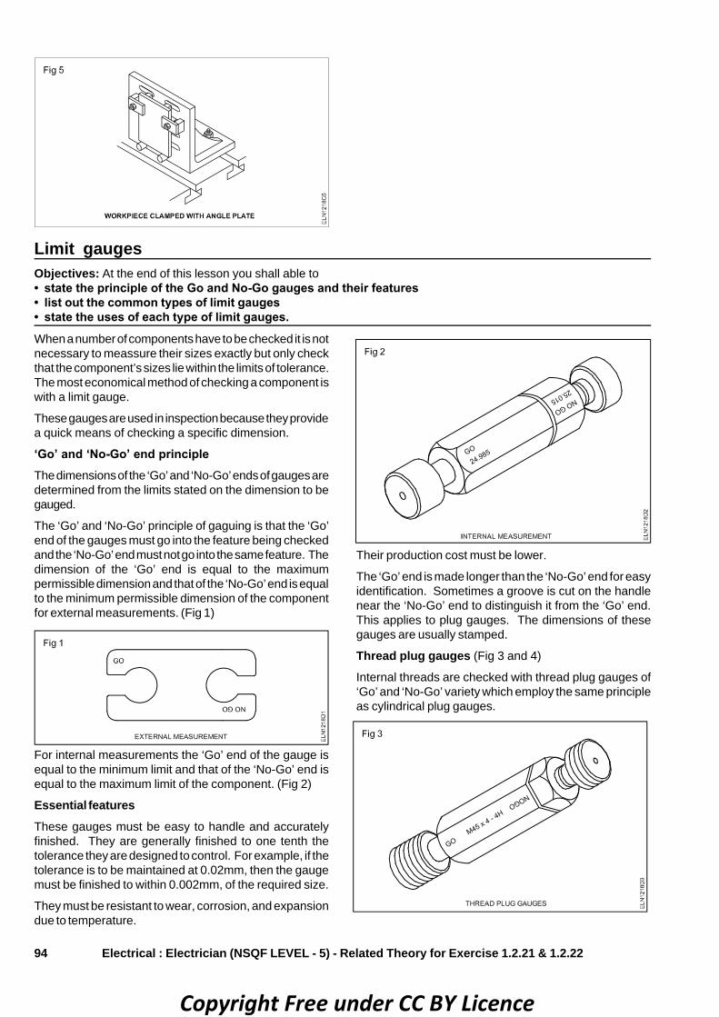
94
Limit gaugesObjectives: At the end of this lesson you shall able to• state the principle of the Go and No-Go gauges and their features• list out the common types of limit gauges• state the uses of each type of limit gauges.
Electrical : Electrician (NSQF LEVEL - 5) - Related Theory for Exercise 1.2.21 & 1.2.22
When a number of components have to be checked it is notnecessary to meassure their sizes exactly but only checkthat the component’s sizes lie within the limits of tolerance.The most economical method of checking a component iswith a limit gauge.
These gauges are used in inspection because they providea quick means of checking a specific dimension.
‘Go’ and ‘No-Go’ end principleThe dimensions of the ‘Go’ and ‘No-Go’ ends of gauges aredetermined from the limits stated on the dimension to begauged.
The ‘Go’ and ‘No-Go’ principle of gaguing is that the ‘Go’end of the gauges must go into the feature being checkedand the ‘No-Go’ end must not go into the same feature. Thedimension of the ‘Go’ end is equal to the maximumpermissible dimension and that of the ‘No-Go’ end is equalto the minimum permissible dimension of the componentfor external measurements. (Fig 1)
For internal measurements the ‘Go’ end of the gauge isequal to the minimum limit and that of the ‘No-Go’ end isequal to the maximum limit of the component. (Fig 2)
Essential featuresThese gauges must be easy to handle and accuratelyfinished. They are generally finished to one tenth thetolerance they are designed to control. For example, if thetolerance is to be maintained at 0.02mm, then the gaugemust be finished to within 0.002mm, of the required size.
They must be resistant to wear, corrosion, and expansiondue to temperature.
Their production cost must be lower.
The ‘Go’ end is made longer than the ‘No-Go’ end for easyidentification. Sometimes a groove is cut on the handlenear the ‘No-Go’ end to distinguish it from the ‘Go’ end.This applies to plug gauges. The dimensions of thesegauges are usually stamped.
Thread plug gauges (Fig 3 and 4)
Internal threads are checked with thread plug gauges of‘Go’ and ‘No-Go’ variety which employ the same principleas cylindrical plug gauges.
Copyright Free under CC BY Licence

95Electrical : Electrician (NSQF LEVEL - 5) - Related Theory for Exercise 1.2.21 & 1.2.22
Thread ring gauges (Fig 5)
These gauges are used to check the accuracy of anexternal thread. They have a threaded hole in the centrewith three radial slots and a set screw to permit smalladjustments.
Copyright Free under CC BY Licence