TRADE OF VEHICLE BODY REPAIR - eCollege€¦ · Vehicle Body Repairs - Phase 2 1 Revision 2.0...
63
TRADE OF VEHICLE BODY REPAIR PHASE 2 Module 3 UNIT: 1 Use of Push/Pull Equipment
Transcript of TRADE OF VEHICLE BODY REPAIR - eCollege€¦ · Vehicle Body Repairs - Phase 2 1 Revision 2.0...

TRADE OF
VEHICLE BODY REPAIR
PHASE 2
Module 3
UNIT: 1
Use of Push/Pull Equipment
Produced by
In cooperation with subject matter expert:
Maurice Stack
Some material courtesy of CDX Global and FENC – Further Education National Consortium.
© SOLAS 2014
Table of Contents
Introduction ....................................................................................................................... 1 Use of Push/Pull Equipment ....................................................................................... 1
Unit Objective ................................................................................................................... 2 Use of Push/Pull Equipment ....................................................................................... 2
1.0 Safety Awareness ........................................................................................................ 3
1.1 Safety Cables when Pulling ..................................................................................... 3
2.0 Different Types of Chassis Constructions ......................................................... 5
2.1 Methods of Construction ....................................................................................... 5
2.2 Types of Chassis and Chassis Frames .................................................................. 7
2.3 Engine Sub Frames ................................................................................................ 10
2.4 Glass Fibre Composite Construction ................................................................. 11
3.0 Jacking Points on a Vehicle Structure .............................................................. 12
3.1 Selection of Suitable Jacking Points .................................................................... 12
3.2 Clamping Method on Composite Structure ...................................................... 13
3.3 Clamping Procedure on an Integral Construction ........................................... 15
4.0 Appropriate Tools and Equipment .................................................................... 19
4.1 Push/Pull Realignment Equipment .................................................................... 19
4.2 Application of the Body Jack ............................................................................... 25
4.3 Upward Pulls and Downward Pulls to Body Panels ........................................ 29
4.4 Dozer Equipment .................................................................................................. 31
4.5 Sway Damage pulls to Front Panel ..................................................................... 32
4.6 Banana Damage ...................................................................................................... 32
4.7 Twist Damage ......................................................................................................... 33
4.8 Diamond Damage .................................................................................................. 33

4.9 Mash Damage ......................................................................................................... 34
4.10 Kick Up/Down .................................................................................................... 35
4.11 Crumple Zones and Safety ................................................................................. 35
4.12 Active Safety ......................................................................................................... 36
4.13 Passive Safety ........................................................................................................ 36
4.14 Steels ....................................................................................................................... 38
5.0 Care and Maintenance of Body Jack ................................................................. 39 6.0 Pulling Systems, Fixed Brake Systems and Similar Pulling System ....... 41
6.1 Operating Principle of the Bracket System........................................................ 41
7.0 Vehicle Mounted on a Car Bench in a Safe and Secure Manner.............. 41
7.1 Vector Realignment Systems ................................................................................ 43
7.2 Realignment, Pull Towers ..................................................................................... 44
Summary ........................................................................................................................... 47 Self Assessment .............................................................................................................. 48 Suggested Exercise............................................................................................................. Training Resources

Table of Figures
Figure 1: Example Forward Pull on Frame Member .................................................. 3
Figure 2: Example Side Pull on Frame Member .......................................................... 4
Figure 3 and 4: Chassis and Chassis Frame.................................................................. 6
Figure 5: Monocoque Construction .............................................................................. 8
Figure 6: Body Construction ........................................................................................... 9
Figure 7: Composite Construction Showing a Lotus Chassis ................................ 11
Figure 8: Suitable Jacking Points ................................................................................... 12
Figure 9: Clamping a Composite Chassis .................................................................... 13
Figure 10: A Vice type Clamping System ................................................................... 15
Figure 11: Snap 4 Tonne Standard Set ......................................................................... 23
Figure 12: Repairs to a Door Opening using a Push Ram ....................................... 24
Figure 13: Push/Pull Realignment Equipment .......................................................... 24
Figure 14: Pushing with Body Jack ............................................................................... 25
Figure 15: Spreading with Body Jack ............................................................................ 26
Figure 16: Clamping with Body Jack ............................................................................ 27
Figure 17: Stretching with Body Jack ........................................................................... 27
Figure 18: Repairs to a Door Opening ........................................................................ 28
Figure 19: Repairs to a Door Opening using Aperture Restraint ............................ 28
Figure 20: Upward Pulls to Body Panels ..................................................................... 29
Figure 21, 22: Downward Pull....................................................................................... 30
Figure 23: Damage Dozer .............................................................................................. 31
Figure 24: Sway Damage ................................................................................................ 32
Figure 25: Banana Damage ............................................................................................ 32

Figure 26: Diamond Damage ........................................................................................ 33
Figure 27: Mash Damage ............................................................................................... 34
Figure 28: Kick Up/Down ............................................................................................ 35
Figure 29: A Section of the High-pressure Hose ....................................................... 39
Figure 30: Vehicle Mounted on a Car Bench ............................................................. 42
Figure 31: Simultaneous Multi-pulls on Two Vehicles (Vector Pulling) ................ 43
Figure 32: Recommended Pulling Angle 45º No Lower .......................................... 43
Figure 33: Simultaneous Multi-pulling using Direct Pulling Towers ...................... 44

Module 3– Unit 1
Vehicle Body Repairs - Phase 2 1 Revision 2.0 January 2014
Introduction
Use of Push/Pull Equipment
Construction
The separate body and chassis construction, in which the chassis resisted the bending and twisting loads so that the body was purely functional, has been superseded by the integral (or mono) construction system. In this construction frame members become an integral part of the body. Box sectioning the body sills, door pillars and roof reinforcements form a framed structure in which the stresses are distributed to all parts of the body.
In the reinforced body shell the problem of primary importance, is to prevent buckling of the body panels. A flat plate offers little resistance to buckling, but curved plates with a single radius, or better still with a double radius, or crown provide excellent resistance; they are also convenient for the construction of a streamlined car.
For stress carrying parts of the body shell, greater rigidity can be achieved by the use of TOP-HAT section, or channel and angles built into the general assembly.
Mass production of car bodies in steel consists of the manufacture of sub-assemblies, usually a floor-pan, two sides, a roof and cross members coming together on the assembly line to be spot welded to form the complete shell. The complete shell as a unit becomes very strong therefore any major damage it sustains has to be repaired with the aid of push/pull equipment.

Module 3– Unit 1
Vehicle Body Repairs - Phase 2 2 Revision 2.0 January 2014
Unit Objective
Use of Push/Pull Equipment
By the end of this unit each apprentice will be able to:
Identify different types of chassis constructions Identify jacking points on a vehicle structure carry out a light
pull Pulling systems, fixed bracket systems and similar pulling
systems Select appropriate tools and equipment Mount a vehicle on a car bench in a safe and secure manner Demonstrate a level of safety awareness
Key Learning Points:
Types of chassis and chassis frames Carry out clamping procedure on integral construction Clamping method on composite structure Engine sub frame Removal of engine sub frame from a mono constructed
chassis Selection of suitable jacking points Sway damage pulls to a front panel Set up a push from main structure to a body panel Upward pulls to body panels Downward pulls to body panels Explain the operating principle of bracket system Vector realignment systems Push/pull realignment equipment Realignment, pull towers Safety cables when pulling Selection of appropriate pulling clamps

Module 3– Unit 1
Vehicle Body Repairs - Phase 2 3 Revision 2.0 January 2014
1.0 Safety Awareness
1.1 Safety Cables when Pulling
Always pull towards the cause of the damage. Use reliable clamps of good quality and always clean area
first remove any sealers dirt etc. For better grip use connected clamps. Always use a safety chain/rope. Connect safety chain/rope to draw clamp. Never stand in the line of the draw liner or draw clamp
during pulling. Always make sure fellow operators are safe. Stand in a safe place when operating vehicle lifting
equipment.
Safety Rope
When safety rope/chain is connected to the draw clamp secure the other end to the bench or draw liner with minimum travel.
Figure 1: Example Forward Pull on Frame Member

Module 3– Unit 1
Vehicle Body Repairs - Phase 2 4 Revision 2.0 January 2014
Figure 2: Example Side Pull on Frame Member

Module 3– Unit 1
Vehicle Body Repairs - Phase 2 5 Revision 2.0 January 2014
2.0 Different Types of Chassis Constructions
2.1 Methods of Construction
The steel body can be divided into two main types: those which are mounted on a separate chassis frame and those in which the under frame or floor forms an integral part of the body. The construction of today’s mass-produced motor car has changed almost completely from the composite, which is conventional separate chassis and body, to the integral or mono unit. This change is the result of the need to reduce body weight and cost per unit of the total vehicle.
Composite Construction (conventional separate chassis)
The chassis and body are built as two separate units. The body is then assembled on the chassis with mounting brackets, which have rubber-bushed bolts to hold the body to the rigid chassis. These flexible mountings allow the body to move slightly when the car is in motion. This means that the car can be dismantled into the two units of the body and chassis. The chassis assembly is built up of engine, wheels, springs and transmission. On to this assembly is added the body, which has been preassembled in units to form a complete body shell.

Module 3– Unit 1
Vehicle Body Repairs - Phase 2 6 Revision 2.0 January 2014
Figure 3 and 4: Chassis and Chassis Frame

Module 3– Unit 1
Vehicle Body Repairs - Phase 2 7 Revision 2.0 January 2014
2.2 Types of Chassis and Chassis Frames
Integral (mono or unity) Construction
Integral body construction employs the same principles of design that have been used for years in the aircraft industry. The main aim is to strengthen without unnecessary weight and the construction does not employ a conventional separate chassis frame for attachment of suspension, engine and other chassis and transmission component. The major difference between composite and integral construction is hence the design and construction of the floor. In integral bodies the floor pan area is generally called the underbody. The underbody is made up of formed floor sections, channels, boxed sections formed rails and numerous reinforcements. In most integral underbodies a suspension member is incorporated in both the front and rear of the body. The suspension members have very much the same appearance as the conventional chassis frame from the underside, but the front suspension members end at the cowl or bulkhead and the rear suspension members end just forward of the rear boot floor. With the floor pan, side rails and reinforcements welded to them, the suspension members become an integral part of the underbody and they form the supports for engine, front and rear suspension units and other chassis components.

Module 3– Unit 1
Vehicle Body Repairs - Phase 2 8 Revision 2.0 January 2014
In the integral body the floor pan area is usually of heavier gauge metal than in the composite body and has one or more box sections and several channel sections which may run across the floor either from side to side or from front to rear, this variety of underbody construction is due largely to the difference in wheelbase, length and weight of the car involved. A typical upper body for an integral constructed car is very much the same as the conventional composite body shell, the major differences lie in the rear seat area and construction which joins the front wings to the front bulkhead or cowl assembly. The construction in the area to the rear of the back seat is much heavier in an integral body than in a composite body. The same is true of the stitching members for the front wings, front bulkhead and floor assembly, as these constructions give great strength and stability to the overall body structure.
Figure 5: Monocoque Construction
Module 3– Unit 1
Vehicle Body Repairs - Phase 2 9 Revision 2.0 January 2014
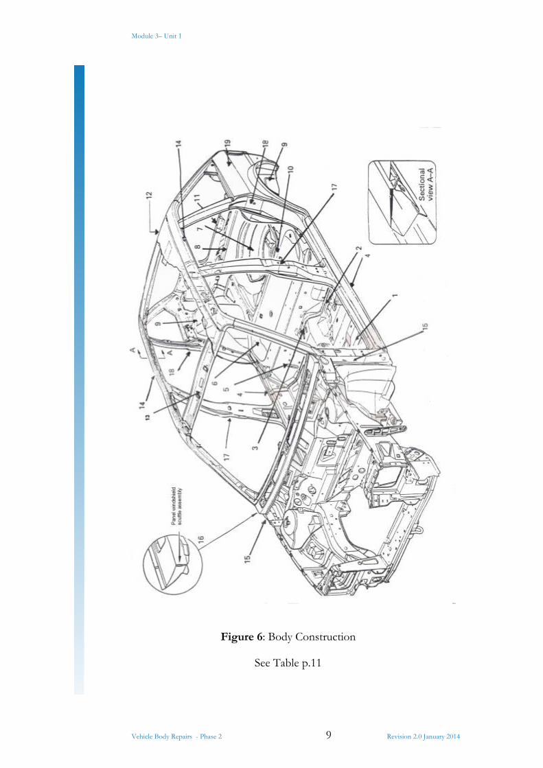
Figure 6: Body Construction
See Table p.11

Module 3– Unit 1
Vehicle Body Repairs - Phase 2 10 Revision 2.0 January 2014
Body Constructional Details of Austin Rover Maestro (Austin Rover)
1 Main floor unit2 Main centre floor panel3 Access holes4 Bottom sills5 Rear seat heelboard6 Rear seat panel7 Boot floor8 Cross member9 Wheel arch panel10 Rear squabs11 Boot lid lock striking plate12 Roof structure13 Windscreen or canopy rail14 Cantrails 15 Front standing pillar (A-post)16 Scuttle 17 Centre standing pillar (BC-post)18 Rear standing pillar (D-post)19 Quarter panels
2.3 Engine Sub Frames
Semi-integral methods of construction
In some forms of integral or mono assemblies, the entire front end or sub frame forward of the bulkhead is joined to the cowl assembly with bolts.
Removal of engine sub frame from a mono constructed chassis
With this construction, the bolt can be easily removed and the entire front (or in some cases rear) sub frame can be replaced as one assembly in the event of extensive damage.

Module 3– Unit 1
Vehicle Body Repairs - Phase 2 11 Revision 2.0 January 2014
2.4 Glass Fibre Composite Construction
This method of producing complex shapes involves applying layers of glass fibre and resin in a prepared mould. After hardening, a strong moulding is produced with a smooth outer surface requiring little maintenance. Among the many shapes available in this composite material are lorry cabs, bus front canopies, container vehicles and the bodies of cars such as the Reliant Scrimitar. The Italian designer, Michelotti, styled the Scimitar body so that separately moulded body panels could be used and overlapped to hide the attachment points. This allows the panels to be bolted directly to the supporting square-section steel tube armatures located on the main chassis frame. The inner body, which rests directly on the chassis frame and which forms the base for all internal trim equipment, is a complex GRP moulding. The windscreen aperture is moulded as a part of the inner body and incorporates steel reinforcing hoops which are braced directly to the chassis. The boot compartment is also a separate hand-laid GRP moulding, as are the doors and some of the other panels. Most of the body panels are secured by self-tapping bolts which offer very positive location and a useful saving in assembly time.
Figure 7: Composite Construction Showing a Lotus Chassis

Module 3– Unit 1
Vehicle Body Repairs - Phase 2 12 Revision 2.0 January 2014
3.0 Jacking Points on a Vehicle Structure
Jacking points are easily identifiable by reinforced sections on the sill panel or by a hole.
3.1 Selection of Suitable Jacking Points
Figure 8: Suitable Jacking Points
Jacking points are the best suited place to mount pull clamps as they are very strong due to reinforcements.

Module 3– Unit 1
Vehicle Body Repairs - Phase 2 13 Revision 2.0 January 2014
3.2 Clamping Method on Composite Structure
Figure 9: Clamping a Composite Chassis
The most common method of clamping a composite chassis is a clamp that fits into existing holes in the chassis. It may also be done by clamping the chassis with a vice type system but the vice system is less secure and may slip when pulling to straighten the chassis.
Module 3– Unit 1
Vehicle Body Repairs - Phase 2 14 Revision 2.0 January 2014
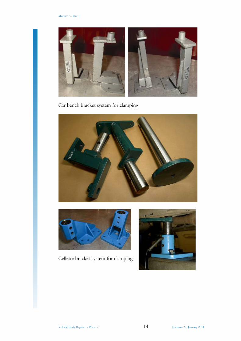
Car bench bracket system for clamping
Cellette bracket system for clamping

Module 3– Unit 1
Vehicle Body Repairs - Phase 2 15 Revision 2.0 January 2014
3.3 Clamping Procedure on an Integral Construction
A vice type clamping system is the most common system used to clamp integral construction vehicles.
Figure 10: A Vice type Clamping System
Cill clamps prevent the vehicle from moving when pulling. When fitting cill clamps make sure they do not hinder the measuring points.
Module 3– Unit 1
Vehicle Body Repairs - Phase 2 16 Revision 2.0 January 2014
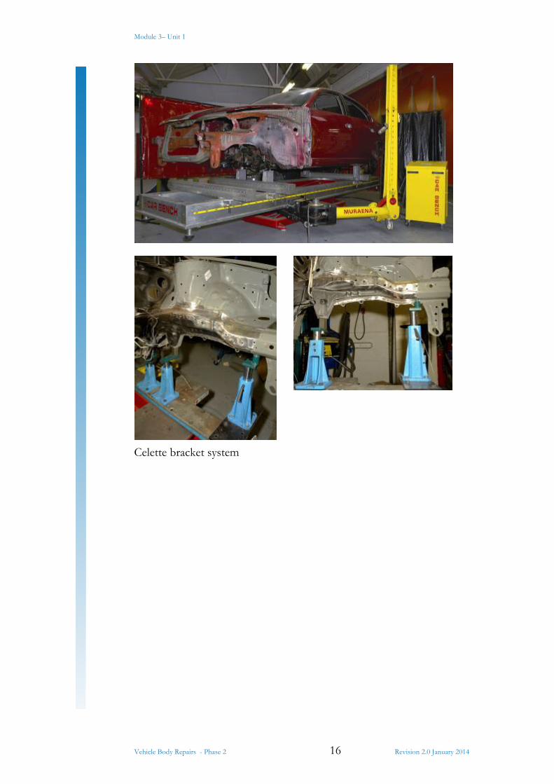
Celette bracket system

Module 3– Unit 1
Vehicle Body Repairs - Phase 2 17 Revision 2.0 January 2014

Module 3– Unit 1
Vehicle Body Repairs - Phase 2 18 Revision 2.0 January 2014

Module 3– Unit 1
Vehicle Body Repairs - Phase 2 19 Revision 2.0 January 2014
4.0 Appropriate Tools and Equipment
4.1 Push/Pull Realignment Equipment
Body jack (hydraulic) development and principles
The evolution in motor car bodywork design and construction has called for many changed methods of handling repairs. This has in turn demanded an increasing amount of repair equipment to augment the traditional hand tools and equipment of the body builder, panel beater and sheet metal worker. Modern equipment has been made necessary by the chassis-less construction of modern mass produced cars and vans, which require careful alignment of the complete structure following any serious impact in addition to panel damage rectification. An essential piece of equipment for repair work is the hydraulic body jack, which is used to push and pull body shells and component body parts into alignment following an accident. Blackhawk Automotive Ltd markets a hydraulic body jack under the name of Porto Power. A range of kits of various sizes is available to suit the needs and capital expenditure of various repair shops. Kits are made-up in carry cases, on wall-board storage and on trolleys incorporating a small press or in form of a bench rack. Attachments and fittings have been developed to use with the body jack equipment.
The use of hydraulic body jacking equipment is not new, nor was it invented suddenly. It has developed to its present sophisticated state over many years. At one time the only type of jack available was the ratchet or screw-type body jack. The use of hydraulic body jacking equipment developed from the use of an ordinary hydraulic jack for this purpose. The hydraulic hand jack had all the advantages of providing tons of closely controlled torque-free power for the minimum of effort by the operator. It soon became apparent that the hydraulic jack was ideally suited to repair work because it could be operated in any plane and controlled from outside the car. In the essential repair of collision work, a large percentage of the work will require the use of the body jack to push or pull large areas or sections back to, approximately, their original positions. Hydraulic body jacks can be extended to any desired length by incorporating a number of attachments which are available for pushing or pulling.
The outer skin, or panels, of a body is made from light-gauge metal, placed over a framework of heavier, stiffened metal which is

Module 3– Unit 1
Vehicle Body Repairs - Phase 2 20 Revision 2.0 January 2014
reinforced with various types of supports and braces, in addition to damage as a result of a collision to the outer panels of the body the

Module 3– Unit 1
Vehicle Body Repairs - Phase 2 21 Revision 2.0 January 2014
inner construction which is attached to the outer panels also becomes damaged, which means that the surface of the outer panel is prevented from being restored to its original contour, hence the inner construction must be restored to its original shape and position either before or at the same time as the outer panel metal is corrected. In some instances it will be found that once the inner construction has been restored to its original position, the outer one will have been corrected at the same time. Before any correction can be made of such damage it is necessary to restore this inner construction. This is generally done by applying pressure to the damaged member or members. Where sharp kinks or creases have been formed at any point in the inner construction, it may be advisable to use heat while the pressure is being applied, but only on low-carbon steel and not on high-strength steel. This permits the metal to return to its original shape with little danger of cracking.
In using the body jack, it is important to understand that pressure is being applied at both ends of the jack simultaneously; therefore there could be a danger of distorting adjacent undamaged panel assemblies during the jacking process if the pushing points are not carefully selected. Such pressure can if necessary be applied either locally or spread over larger areas by the introduction and use of pressure pads, which are usually hard wood blocks. The body jack is also useful for providing support or pressure at otherwise inaccessible portions of the outer panels, as well as applying controlled pressure in a higher degree than is possible with hand tools on the various panels.

Module 3– Unit 1
Vehicle Body Repairs - Phase 2 22 Revision 2.0 January 2014
Basic Equipment
A body jack consists of three basic units, a pump, a flexible hose connecting pump to ram and the ram unit. The pump comprises reservoir, pump handle and hose and is controlled by a simple open and close release valve. The handle can be screwed into the pump in two different positions for ease of operation. The hose is connected to the ram by a simple quick release coupler which needs to be only finger tight. Pressure is applied by closing the pump release valve and operating the pump handle. The pump will build up sufficient pressure only to overcome the external resistance against the ram. The need to apply excessive pressure to the pump handle indicates that the ram has reached the limit of its movement. The ram is designed with a snap-on system to enable extension tubes and attachments to be positioned to harness the hydraulic power for any desired type of application.
All collision damage repair work which makes use of the body jack equipment is carried out by using one or another of a number of simple set-ups or, in the case of more complicated repair, a combination of set-ups. The first important step
therefore is to understand the set-ups that can be built with this application; then it is a question of breaking down a job into its basic set-ups and applying the corrective force in the correct sequence. The corrective force should be applied as near as possible in the direction opposite to the force which caused the damage. The body jack set-up should be applied as not to push at the deepest point on the damaged section; instead work round the outer edges in ever-decreasing circles which will tend to spring the remaining damage into the final position. If the body jack set-up is applied directly against the lowest part of a damaged section without relieving the strain, then as the pressure is applied the metal surface may become kinked and stretched and require further attention to return it to its correct level.

Module 3– Unit 1
Vehicle Body Repairs - Phase 2 23 Revision 2.0 January 2014
Figure 11: Snap 4 Tonne Standard Set
Snap 4Tonne Standard Set Supplied for Carrying Case
1 Manual pump with hose2 4-T bantam hydraulic hose. 18m3 4-T ram toe4 Extension tubes5 Snap flex head6 90º V base7 Tube connector8 Serrated saddle9 Wedge head10 Plunger toe11 Chain pull collar12 Spread ram – wedge ram13 Flat base

Module 3– Unit 1
Vehicle Body Repairs - Phase 2 24 Revision 2.0 January 2014
Figure 12: Repairs to a Door Opening using a Push Ram
Repairs to a door opening using a single Pull/Push, figure 12 shows rectification to a door opening using a push ram connected at both ends to push-pull clamps, which are bolted on to the door flange edges. The doors are left suspended on their hinges to act as templates during the operation.
Figure 13: Push/Pull Realignment Equipment
Repairs to boot lid aperture and rear windscreen using a combination of set-ups. Where the rear of the car becomes accidentally pushed in, the panels can be returned to there correct alignment in the manner illustrated in figure 13. The jack is placed across the aperture of the boot lid, with a wedge head attached to one end and the rubber flex head to the other. This is to spread the force of the pressure evenly over a larger area.

Module 3– Unit 1
Vehicle Body Repairs - Phase 2 25 Revision 2.0 January 2014
The boot lid, when repaired or replaced, is fitted in position and will act as a guide for alignment when pushing out the surround panel. A rear windscreen opening can be restored to its original shape by placing the body jack diagonally across the corners which are out of square. Where the standard rubber flex head does not suit the shape of the body, the wide-angled wedge head must be used.
4.2 Application of the Body Jack
Pushing
Pushing is the simplest operation of all and is achieved by inserting the ram between two points and operating the pump. The plunger extends until it touches the point at which the load is to be applied and as pumping is continued pressure is built up to overcome the resistance of the metal at the point of application. Movement of the damaged area will take place as long as pumping is continued.
Care must be taken when selecting a ram anchor: for example, if a ram was placed between two chassis members and it was intended to push from the undamaged members to straighten the damaged member, the force applied would not rectify the damage but would distort the undamaged member. The first essential is to ensure that the pushing anchor point is stronger than the point which is receiving the corrective force. This can be done by attaching a base plate to the bottom end of the ram to spread or distribute the load, which can be spread over an even larger area by putting a piece of solid hardwood timber between the base plate and the pushing point. It is seldom that a pushing application can be achieved using the ram only, because of its limited travel: therefore there are available various combinations of extension tubes, couplings and pusher heads to cater for any repair requiring a straightforward push.
Figure 14: Pushing with Body Jack

Module 3– Unit 1
Vehicle Body Repairs - Phase 2 26 Revision 2.0 January 2014
Spreading
Spreading is a similar application to pushing except that in the latter case there is sufficient room for access of the ram and extension between the two members to be moved apart to permit a direct push. When this is not possible a means must be found of inserting jaws or attachments which are capable of applying an indirect thrust. The most obvious means of spreading is provided by the wedgies and spread rams.
This is an off-centre load once more and even under the most favourable conditions it is not possible to apply a force of more then about 7 tonnes with the 10 tonne ram, or 2.5 tonnes with the 4 tonne ram.
Figure 15: Spreading with Body Jack
Stretching or Tensioning
The technique of stretching or tensioning is another means of obtaining a pull using a push ram. It is different from the type of pulling previously described, which was a method of applying force to pull towards one another, sections which have been forced apart. Here the reverse takes place and an external pull is applied to pull apart or draw outwards areas that have been pushed or drawn in towards each other. The combination used to obtain this external pull employs toes, links and clamps on the end of the push ram and extension tubes. Two types of clamps are used, the pull clamps for attachment to flat edges and the wing clamps which have deep throats or lipped edges. Both clamps have an alligator type of action and are first tightened down on the centre bolt until the jaws are parallel and in contact with the surface of the panel to be gripped. Pressure is then applied by tightening the rear bolt, which cants the

Module 3– Unit 1
Vehicle Body Repairs - Phase 2 27 Revision 2.0 January 2014
jaws forward and causes them to bite into the surface of the metal. It may well be that the time taken to set up this combination is greater than the time to pull out the damage once it is in position. On flat panels where it is not possible to get at the edges or where there is not an edge to locate a clamp, the same result can be achieved by locating the toes in the bosses of a pair of solder plates which have been sweated on to the panel. A roof panel or car door is a typical example of this. To get at both edges of a car door it is usually necessary to remove the door, but this can be eliminated by using a clamp at the free edge of the door and solder plate will withstand a pull of 13800 kN/m². The plates should be sweated on with a layer of body solder about 3mm thick, using the minimum of heat and quenching with a wet rag to prevent distortion. The same technique may be applied to boot lids, front wings, bonnets and rear quarter panels, and can be the means of repairing a panel in a position where direct pressure from inside would not have achieved a satisfactory result. Another combination, which is less popular in use, is clamping.
Figure 16: Clamping with Body Jack
Figure 17: Stretching with Body Jack

Module 3– Unit 1
Vehicle Body Repairs - Phase 2 28 Revision 2.0 January 2014
Example of use of a Body Jack
Figure 18 demonstrates the jack being used diagonally to rectify a door opening. Pressure is applied until the clearance round all sides of the door is equal and it opens and closes freely.
Note: The use of a pull ram fitted with chains and connected to a swivel clamp at the upper corner and a pull ring and clamp at the lower corner.
Figure 18: Repairs to a Door Opening
Figure 19: Repairs to a Door Opening using Aperture Restraint
Module 3– Unit 1
Vehicle Body Repairs - Phase 2 29 Revision 2.0 January 2014
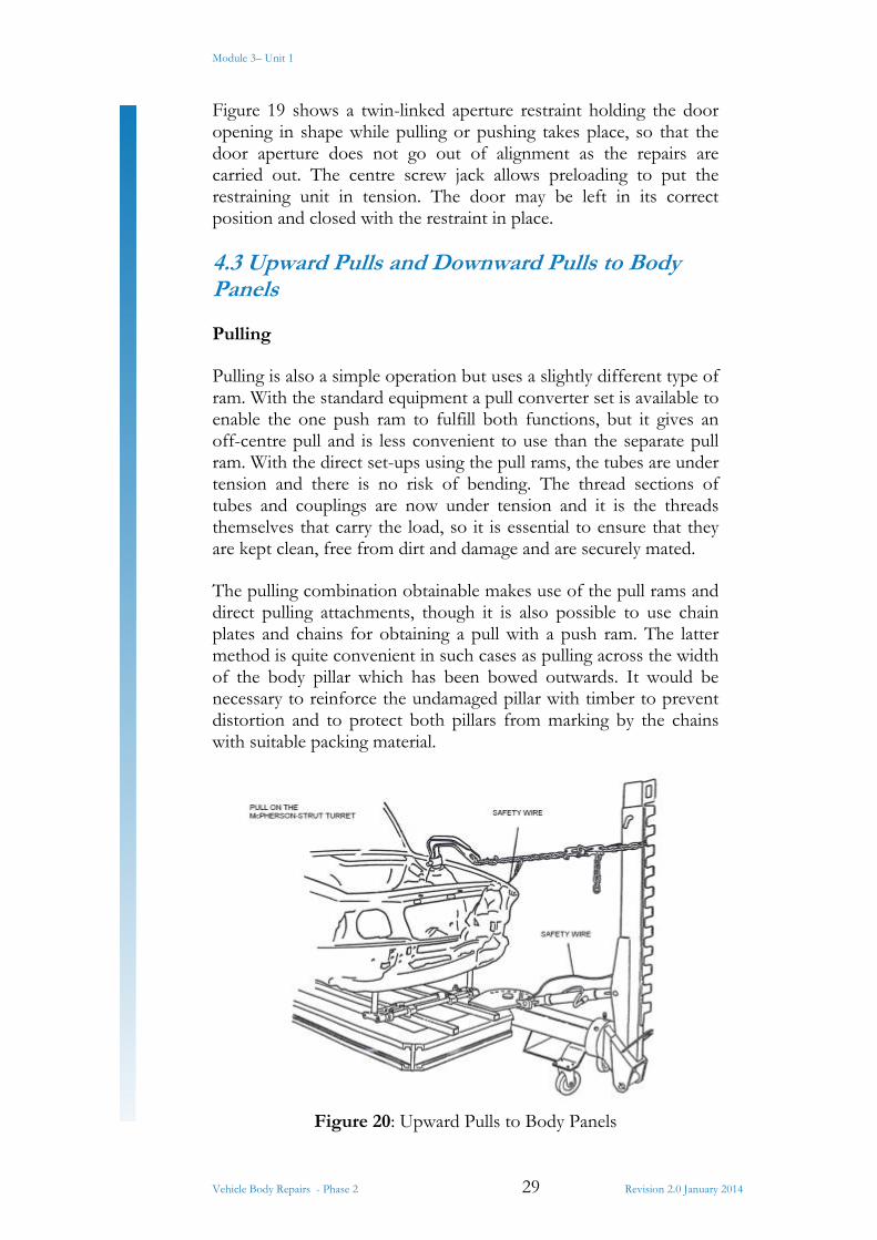
Figure 19 shows a twin-linked aperture restraint holding the door opening in shape while pulling or pushing takes place, so that the door aperture does not go out of alignment as the repairs are carried out. The centre screw jack allows preloading to put the restraining unit in tension. The door may be left in its correct position and closed with the restraint in place.
4.3 Upward Pulls and Downward Pulls to Body Panels
Pulling
Pulling is also a simple operation but uses a slightly different type of ram. With the standard equipment a pull converter set is available to enable the one push ram to fulfill both functions, but it gives an off-centre pull and is less convenient to use than the separate pull ram. With the direct set-ups using the pull rams, the tubes are under tension and there is no risk of bending. The thread sections of tubes and couplings are now under tension and it is the threads themselves that carry the load, so it is essential to ensure that they are kept clean, free from dirt and damage and are securely mated.
The pulling combination obtainable makes use of the pull rams and direct pulling attachments, though it is also possible to use chain plates and chains for obtaining a pull with a push ram. The latter method is quite convenient in such cases as pulling across the width of the body pillar which has been bowed outwards. It would be necessary to reinforce the undamaged pillar with timber to prevent distortion and to protect both pillars from marking by the chains with suitable packing material.
Figure 20: Upward Pulls to Body Panels

Module 3– Unit 1
Vehicle Body Repairs - Phase 2 30 Revision 2.0 January 2014
Downward Pulls to Body Panels
Figure 21, 22: Downward Pull

Module 3– Unit 1
Vehicle Body Repairs - Phase 2 31 Revision 2.0 January 2014
4.4 Dozer Equipment
Blackhawk Automotive Ltd have a portable pulling frame that can be taken to the car in any part of the body repair shop and then moved on to the next job once straightening has been completed. This frame is called Dozer and is designed to cater for various classes of repair work. The Dozer is designed for heavy major frame and body.
Figure 23: Damage Dozer
Specification of AEK - 614
Pivot arm, Ht: 1.67m, Length: 3.00m, Caster Dia: 100mm, Weight: 274.2kg, Capacity 10 ton.
1 Basic frame assembly 9 Pull clamp2 Air hydraulic unit 10 Pull ring3 Extension beam 11 Multi-position anchor post 4 Support stands - cross tube 12 Multipull dozer hook 5 Underbody clamps (pair) 13 Frame horn puller 6 Cross tube clamps (pair) 14 Chain with 2 hooks 2.70m 7 Chain positioning loop 15 Chain with 1 hook 2.70m 8 Multi-direction, self
tightening clamp 16 Tram track gauge

Module 3– Unit 1
Vehicle Body Repairs - Phase 2 32 Revision 2.0 January 2014
4.5 Sway Damage pulls to Front Panel
Sway damage can be caused to the front or the back of a vehicle, but is most likely and most noticeable to the front due to the box shape of the engine bay. Sway damage is best repaired on a repair bench although slight sway damage can be repaired using independent hydraulic repair equipment. If the front section of the vehicle moves across uniformly then chances are it will return uniformly. If it does not move uniformly i.e. top of the front end moves more than the lower part then it is very likely that it will not realign uniformly. The engine may hold a chassis in position but allow the McPherson tower to move. This type of misalignment is difficult to repair as there is no natural restoration pulls.
Figure 24: Sway Damage
4.6 Banana Damage
Banana damage is caused by severe side impact. Light side damage will not cause banana damage. The effect is caused by shortening of the impacted side. This has the effect of closing the side gaps. The primary pulls are set up as usual is in the opposite direction of the impact, this may help restore the gaps, but generally a pull to one or both ends to stretch the vehicle is usually necessary. Banana damage can be identified by the loss of door gaps on the damaged side and the opening of gaps on the opposite side. Irregular gaps to the bonnet/wings and rear boot are a clear sign of banana damage. The use of a repair bench is vital.
Figure 25: Banana Damage
Module 3– Unit 1
Vehicle Body Repairs - Phase 2 33 Revision 2.0 January 2014
4.7 Twist Damage
Twist damage usually occurs to independent frames. The material is so hard the chassis does not mash on impact but bends up or down. This bending usually causes a deformation to the entire chassis resulting in a twisting effect. It is difficult to repair this damage as visibility and access is restricted. Some times it is necessary to remove the body from the chassis but this is time consuming and on a practical level usually results in the vehicle creaking after with obvious customer complaints.
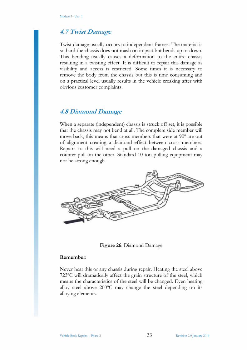
4.8 Diamond Damage
When a separate (independent) chassis is struck off set, it is possible that the chassis may not bend at all. The complete side member will move back, this means that cross members that were at 90º are out of alignment creating a diamond effect between cross members. Repairs to this will need a pull on the damaged chassis and a counter pull on the other. Standard 10 ton pulling equipment may not be strong enough.
Figure 26: Diamond Damage
Remember:
Never heat this or any chassis during repair. Heating the steel above 723ºC will dramatically affect the grain structure of the steel, which means the characteristics of the steel will be changed. Even heating alloy steel above 200ºC may change the steel depending on its alloying elements.

Module 3– Unit 1
Vehicle Body Repairs - Phase 2 34 Revision 2.0 January 2014
Heat treatment changes grain structure
4.9 Mash Damage
Mash damage or accordion damage as it is called is where the structures collapse in a linear direction. The chassis creases and folds. The effect is like that of an accordion. A good easy to understand example is a VW Vento or Passet chassis. The main difficulty with this type of chassis is that it is difficult to arrest the deformation once it has started.
Figure 27: Mash Damage

Module 3– Unit 1
Vehicle Body Repairs - Phase 2 35 Revision 2.0 January 2014
4.10 Kick Up/Down
Modern front wheel drives can take advantage of the kick up/down effect. If a crash force is applied at (A) the front sections deforms and rides up pivoting at (B). This movement can be arrested by the increasing section of the chassis as it joins the bulkhead at (C). Serious front end damage can result in an inertia reaction which may result in the rear chassis rising. This may or may not return to its original height after front end realignment.
Figure 28: Kick Up/Down
4.11 Crumple Zones and Safety
Crumple zones are usually found in chassis legs and with regards to bodywork, the vehicle manufacturers take into account the safety of the driver, passengers and other road users. Although the vehicle can not be expected to withstand collision with objects or other vehicles, much can be done to reduce effects of collision by the use of careful design of overall be done to reduce effects of collision by the use of careful design of overall shape, the selection of suitable materials and the design of the components. The chances of injury can be reduced both outside and inside the vehicle avoiding sharp-edged, projecting elements.
Module 3– Unit 1
Vehicle Body Repairs - Phase 2 36 Revision 2.0 January 2014
Every car is to be designed with the following Crash Safety Principles in mind:
The impact from a collision is absorbed gradually by controlled deformation of the parts of the car body if possible.
The passenger area is kept intact as long as possible.
The interior is designed to reduce the risk of injury.
Safety-related vehicle laws cover design, performance levels and the associated testing procedures, requirements for tests, inspections, documentation and records for the process of approval; check the standards are being maintained during production, the issue of safety-related documentation, and many other requirements throughout the vehicle’s service life.
4.12 Active Safety
This refers to the features designed into the vehicle which reduce the possibility of an accident. These include primary design elements such a dual-circuit braking systems, anti-lock braking systems, high aerodynamic stability and efficient bad weather equipment, together with features that make the driver’s environment safer, such as efficient through ventilation, orthopaedic seating, improved all-round vision, easy to read instruments and ergonomic controls. An anti-lock braking system (ABS) enhances a driver’s ability to steer the vehicle during hard braking.
4.13 Passive Safety
If a crash does happen, passive safety features should protect the passengers by:
Making sure that, in the event of an accident, the occupants stay inside the car.
Controlling the magnitude and duration of the deceleration to which they are subjected.
Restraining the occupants so that they are not injured by secondary impacts within the car.
Designing the outside of the vehicle so that the least possible injury is caused to pedestrians and others who may come into contact with the outside of the vehicle.

Module 3– Unit 1
Vehicle Body Repairs - Phase 2 37 Revision 2.0 January 2014
Manufacturers are now fitting automatic seatbelt tensioners. These automatic ‘body lock’ front seatbelt tensioners reduce the severity of head injuries by 20 per cent with similar gains in chest protection. In impacts over 20kph (12 mph) the extra tension in the seatbelts buckle triggers a sensor which tightens the lap and diagonal belts in 22 milliseconds, that is before the occupant even starts to move. Anti-submarine ramps built into front seats further aid safety by reducing the possibility of occupants sliding under the belt. There are also engineering features such as impact energy-absorbing steering columns, head restraints, bumpers, anti-burst door locks.
The vehicle structure can be designed to deform at pre-determined loads. Some of the ways that allow this to happen is the use of:
Notches at the corners of the chassis. Swage lines. (like those on a panel radiator) Changing the sections of a chassis. Suddenly is more
effective. Changing the direction of a chassis. Gentle curving of a
chassis increases strength and makes identifying damage difficult.
Holes in a chassis will cause collapse. Square holes are more effective than round holes.
To avoid mistakes it is vital that cut and join locations, are only chosen in accordance with a repair manual. If correct location and methods are used, and welds etc of a suitable quality are used, then the best repair technique has been used.
Remember: During impact a range of contrasting can be applied to a structure or even a single panel i.e. tensile, compressive, shear and twisting forces can be applied. Any joint selected must be capable of resisting reasonable forces.

Module 3– Unit 1
Vehicle Body Repairs - Phase 2 38 Revision 2.0 January 2014
4.14 Steels
Steel is the preferred choice of material for car bodies.
It can be formed into complex shapes without fracture. It can be modified to change its essential characteristics. It will bend and deform during impact. This is critical to
crash safety performance. It allows a range of thermal processes to be used for joining. It allows repair and painting to its surface. Compared to most other materials which could give the
required characteristics it’s cheap.
Iron ore is mined from the ground, melted and carbon added. The usual amount of carbon added is 0.15 – 0.70%. the carbon changes its characteristics to such an extent that steel with carbon content of 0.25 – 0.30% carbon are used to make steel suitable for car bodies. This has suitable hardness while allowing the shaping necessary to manufacture vehicle body parts. When greater stiffness or tensile strength is required, adding more carbon will result in a harder panel but also a more brittle panel. Therefore other methods are used to change the characteristics. This may include heating the steels and controlling the cooling rate, or work hardening the steel. When a steel is of 0.25% - 0.30% carbon and is not work hardened then the steel is known as mild steel. This was the type of steel used up until the early mid 1980s. Currently a large percentage of cars have a significant percentage of mild steel panels. Instead of adding carbon some manufacturers add other elements to give the steel better properties. Most of these newer steels are heat treated to enhance their characteristics.

Module 3– Unit 1
Vehicle Body Repairs - Phase 2 39 Revision 2.0 January 2014
5.0 Care and Maintenance of Body Jack
As with all hydraulic equipment, little trouble is experienced with the working of the jack provided the unit is kept free from oil leaks. When topping up with oil it is necessary to use the correct type of oil. Take care not to allow any dirt or grit to enter the oil track while adding or checking the oil level. Air sometimes becomes trapped in the oil track, in which case it is necessary to bleed the pump.
Bleeding the Body Jack
Clamp the pump in a vice. Close the release valve and operate the pump handle until the ram plunger is fully extended. If the plunger will not move by pumping, withdraw it by hand. Remove the filler plug from the end of the pump and release the valve. Place the plunger on the floor and slowly push down until it collapses, expelling all the air. Pump the handle rapidly then close the release valve and replace the filler plug. The unit is now ready for operating.
Care of the Hose
On remote control jacks, where the hydraulic pressure is supplied to the ram through a hose, it is well to exercise care so that the hose does not become damaged. The hose is made from oil proof rubber reinforced by woven steel wire which is covered on the outside by a fabric and rubber combination. Do not permit heavy objects to fall or drop on the hose, as a sharp, hard impact may kink the wire strands in the hose. Because of the rubber covering, the kink may not be noticeable and the application of pressure will eventually cause the strands to break and the hose will leak. In making set-ups with the jack, always be careful to anchor the ram unit so that its pushing force will not tend to bend or break the hose fittings.
Care of Threads on Ram and Attachments
When the ram is not in use, attachments provided for protection of the plunger thread and ram body should be in place.
Figure 29: A Section of the High-pressure Hose
Module 3– Unit 1
Vehicle Body Repairs - Phase 2 40 Revision 2.0 January 2014
Use all of the threads to make connections and always turn the attachments until they are tight. Always keep the threads in all attachments clean and free from grease. Whenever threads become bent or damaged, they should be repaired so that the proper fit can be obtained when connections are made. Most attachments are now snap-on connections and therefore have no threads and need no maintenance.

Module 3– Unit 1
Vehicle Body Repairs - Phase 2 41 Revision 2.0 January 2014
6.0 Pulling Systems, Fixed Brake Systems and Similar Pulling Systems
6.1 Operating Principle of the Bracket System
See Module 3. Unit 5. Repair Benches
7.0 Vehicle Mounted on a Car Bench in a Safe and Secure Manner
Mounting a medium size vehicle can be achieved quickly by one person using bolts for anchoring the vehicle.
1. Push vehicle over bench, no winch needed.
2. Raise vehicle with lift. Fast air/hydraulic pump, place wheel stands under vehicle wheels.

Module 3– Unit 1
Vehicle Body Repairs - Phase 2 42 Revision 2.0 January 2014
3. Lower vehicle onto wheel stands. Mount bench brackets, mount chassis clamps (4 bolts).
Figure 30: Vehicle Mounted on a Car Bench
4. Raise vehicle to a comfortable working position, to commence repairs.

Module 3– Unit 1
Vehicle Body Repairs - Phase 2 43 Revision 2.0 January 2014
7.1 Vector Realignment Systems
With the vector method of pulling, parallel pulling can be carried out in the following way: first connect the chain to the damaged part of the car, and then hold the chain tightly in the direction you wish to pull and adjust the pulling unit or ram to the measured angle. It is not necessary to have the chain vertically in line with the direction of pull, but it is lower than 45 degrees: that the chain links are set in line without any twist: and that the chain between the ram and chain anchor point should always lean towards the vehicle. As soon as tension is applied to the chain, safety wires must be fitted in case the clamp or chain tears away from the main structure of the car.
Figure 31: Simultaneous Multi-pulls on Two Vehicles (Vector Pulling)
Figure 32: Recommended Pulling Angle 45º No Lower

Module 3– Unit 1
Vehicle Body Repairs - Phase 2 44 Revision 2.0 January 2014
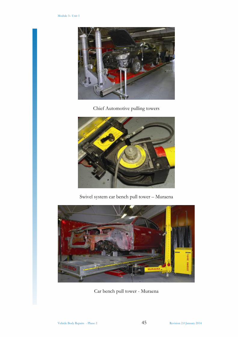
7.2 Realignment, Pull Towers
Figure 33: Simultaneous Multi-pulling using Direct Pulling Towers
Vector pull tower - Blackhawk
Module 3– Unit 1
Vehicle Body Repairs - Phase 2 45 Revision 2.0 January 2014
Chief Automotive pulling towers
Swivel system car bench pull tower – Muraena
Car bench pull tower - Muraena

Module 3– Unit 1
Vehicle Body Repairs - Phase 2 46 Revision 2.0 January 2014
Selection of Appropriate Pulling Clamps

Module 3– Unit 1
Vehicle Body Repairs - Phase 2 47 Revision 2.0 January 2014
Summary
To repair damaged motor body panels requires great skill in the use of hand tools and repair techniques and an ability to assess the cause, extent and sequence of the damage sustained. Damage by accident and its subsequent repair covers a wide range of incidents from minor scratches and cosmetic damage to the write-off. The repair will only be approved by an insurance company after considering the car’s age, condition and relevant market value.
Vehicle body repair work can be divided basically into two groups, minor accident repair work and major accident repair work. This is where an experienced vehicle body repairer decides the course of action, its important to know the limits you can go to.

Module 3– Unit 1
Vehicle Body Repairs - Phase 2 48 Revision 2.0 January 2014
Self Assessment
Questions – Module 3. Unit 1
1. What must be done before fitting a draw clamp?
2. Before pulling what safety equipment must be fitted?
3. What position is forbidden to stand when a draw liner is in use?
4. What is a mono construction?
5. What is a composite construction?

Module 3– Unit 1
Vehicle Body Repairs - Phase 2 49 Revision 2.0 January 2014
6. Give an example of glass fibre composite construction.
7. Name two manufacturers of bracket systems?
8. What is a body jack?
9. What is a vector pull system?
10. What pulling equipment pulls in many directions at once?
11. Where would you find a crumple zone?

Module 3– Unit 1
Vehicle Body Repairs - Phase 2 50 Revision 2.0 January 2014
12. What is a fixed bracket system?
13. What prevents the hydraulic hose from damage?
14. When a car receives banana damage what happens to the gaps on the opposite side?
15. What provides the pulling force in a body dozer?
16. What does the wedge ram do?
17. Is a dozer used to pull a chassis?

Module 3– Unit 1
Vehicle Body Repairs - Phase 2 51 Revision 2.0 January 2014
18. What type of clamp is used to hold a vehicle while pulling it?
19. What is sway damage?
20. What is the upper heat critical limit?

Module 3– Unit 1
Vehicle Body Repairs - Phase 2 52 Revision 2.0 January 2014
Answers to Questions 1-20. Module 3. Unit 1
1.
Clean pinch weld area thoroughly.
2.
Safety rope
3.
In the line of the pull.
4.
One piece construction (unity)
5.
Two piece construction (separate chassis)
6.
Lotus

Module 3– Unit 1
Vehicle Body Repairs - Phase 2 53 Revision 2.0 January 2014
7.
Car bench - Celette
8.
A hydraulic pushing pulling device.
9.
A vector pull system is a system used to pull a chassis back into place.
10.
A vector pulling system.
11.
Chassis leg.
12.
A repair system that uses non adjustable brackets to realign the vehicle.

Module 3– Unit 1
Vehicle Body Repairs - Phase 2 54 Revision 2.0 January 2014
13.
The woven steel wire.
14.
The gaps widen
15.
The ram
16.
Widens panels
17.
Yes, a dozer is used to pull a chassis.
18.
Sill clamps
Module 3– Unit 1
Vehicle Body Repairs - Phase 2 55 Revision 2.0 January 2014
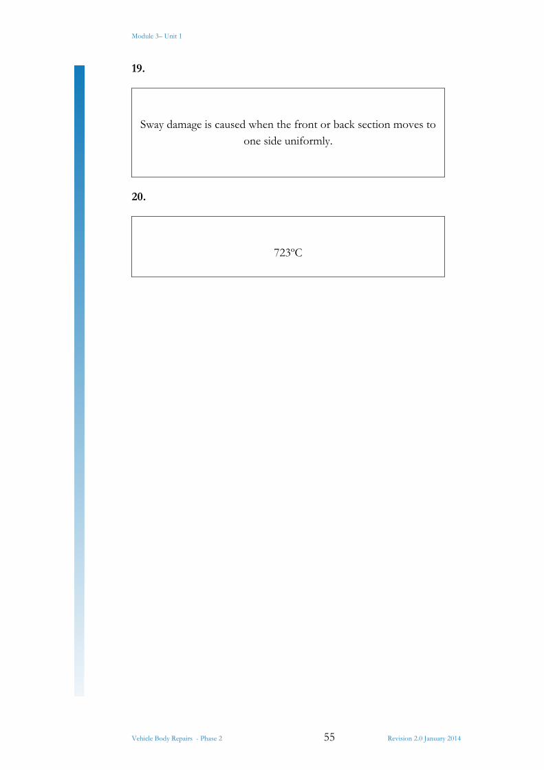
19.
Sway damage is caused when the front or back section moves to one side uniformly.
20.
723ºC
Suggested Exercise
Exercise
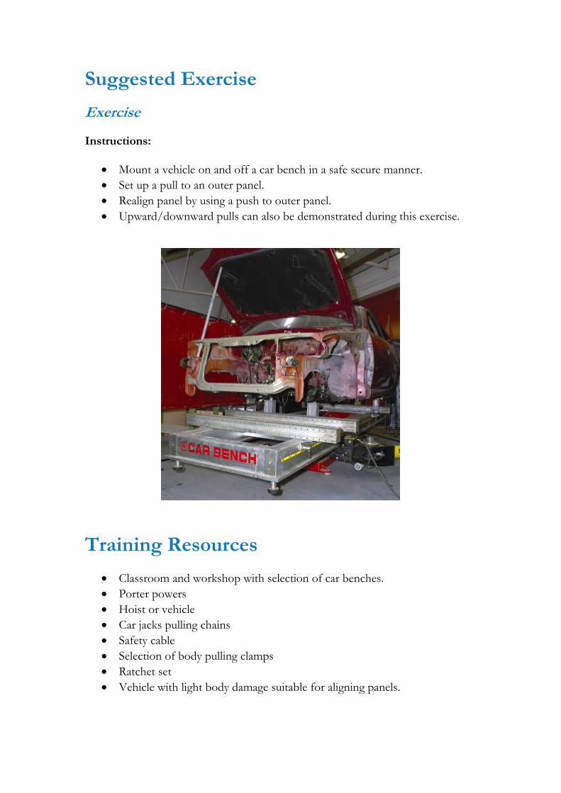
Instructions:
Mount a vehicle on and off a car bench in a safe secure manner. Set up a pull to an outer panel. Realign panel by using a push to outer panel. Upward/downward pulls can also be demonstrated during this exercise.
Training Resources
Classroom and workshop with selection of car benches. Porter powers Hoist or vehicle Car jacks pulling chains Safety cable Selection of body pulling clamps Ratchet set Vehicle with light body damage suitable for aligning panels.

27-33 Upper Baggot Street Dublin 4