Trade of Metal Fabrication - Solas...
27
Trade of Metal Fabrication Module 5: Pipe Fabrication Unit 1: Introduction to Pipes and Tubes Phase 2
Transcript of Trade of Metal Fabrication - Solas...

Trade of Metal Fabrication Module 5: Pipe Fabrication
Unit 1: Introduction to Pipes and Tubes
Phase 2


Trade of Metal Fabrication – Phase 2 Module 5 Unit 1
Unit 1 3
Table of Contents
List of Figures .................................................................................................................... 5
List of Tables ..................................................................................................................... 5
Document Release History ............................................................................................... 6
Module 5 – Pipe Fabrication ............................................................................................ 7
Unit 1 – Introduction to Pipes and Tubes ....................................................................... 7 Learning Outcome: ..................................................................................................... 7 Key Learning Points: .................................................................................................. 7 Training Resources: .................................................................................................... 7 Key Learning Points Code: ......................................................................................... 7
Cross-Sectional Area ........................................................................................................ 8
Volume of Metal ................................................................................................................ 9
Capacity ............................................................................................................................. 9
Example 1 ..................................................................................................................... 10 Example 2 ..................................................................................................................... 10
Mild Steel Pipe & Fittings .............................................................................................. 10
Apprentice Plumbing .................................................................................................... 11 Mild Steel Pipe Identification ....................................................................................... 13 Mild Steel Pipe Assembly ............................................................................................. 17
Piping Fabrication and Erection ................................................................................... 18
Piping Fabrication ......................................................................................................... 18 Fabrication Drawings ................................................................................................ 19 Fabrication Specifications ......................................................................................... 19
Mechanical and Structural Engineering ........................................................................ 21
Colour Codes for the Contents of Pipes ........................................................................ 23
Carbon Content in Steel ................................................................................................. 24
Practical Effect of the Variation in the Carbon Content of Steels in the Hardening and Tempering Operations .................................................................................................. 24
Hardening .................................................................................................................. 24 Tempering ................................................................................................................. 24
Classification of Carbon Steels ..................................................................................... 24 Low-Carbon Steel ......................................................................................................... 24 Medium-Carbon Steels ................................................................................................. 25 High and Very-High-Carbon Steels .............................................................................. 25 Importance of Carbon in Steel ...................................................................................... 25

Trade of Metal Fabrication – Phase 2 Module 5 Unit 1
Unit 1 4
Other Factors Altering Strength and Structure ............................................................. 25
Self Assessment................................................................................................................ 26
Index ................................................................................................................................. 27

Trade of Metal Fabrication – Phase 2 Module 5 Unit 1
Unit 1 5
List of Figures
Figure 1 - Mild Steel Pipe Cutting .................................................................................... 11
Figure 2 - Thread Cutting ................................................................................................. 12
Figure 3 - Mild Steel Pipe Identification 1 ....................................................................... 14
Figure 4 - Mild Steel Pipe Identification 2 ....................................................................... 15
Figure 5 - General View of a Pipe Fabrication Shop ........................................................ 18
Figure 6 - Pipebank being Hydraulic Tested in Test Bay ................................................. 20
Figure 7 - B.I.C.I.'s Olefines Plant at Wilton, Teeside ..................................................... 21
Figure 8 - Plate C. A Section of I.C.I.'s Olefines Plantat Wilton, Teeside ....................... 22
List of Tables

Trade of Metal Fabrication – Phase 2 Module 5 Unit 1
Unit 1 6
Document Release History
Date Version Comments
08/02/07 First draft
13/12/13 SOLAS transfer

Trade of Metal Fabrication – Phase 2 Module 5 Unit 1
Unit 1 7
Module 5 – Pipe Fabrication
Unit 1 – Introduction to Pipes and Tubes
Duration – 2 Hours
Learning Outcome:
By the end of this unit each apprentice will be able to:
Identify types, construction and application of pipes and tubes
Read and interpret pipe conventions and schedules
Describe the production of pipes - seamed/seamless
Describe the effects of carbon content on the properties of steels
Calculate the cross-sectional area of pipes and the volume of metal in pipes
Key Learning Points:
Rk Production of pipes and tubes.
Rk Sk Pipe types, construction and applications.
Rk Colour coding – conventions.
Sk Pipe cutting – hacksaw, bandsaw, pipecutters (hand/mechanical).
M Mensuration (cross-sectional areas – volume of metal).
Rk Effects of carbon content on properties of steels.
H Speeds/feed of bandsaw blades – TPI of blades.(For more information see Module 1 Unit 6).
M Calculating cross-sectional area and volume of pipes.
P Effective communication, interpreting instructions.
Training Resources:
Classroom and lecture facilities
Fabrication workshop and equipment
Pipe sections
Sample of types of pipes
Handouts, notes and technical manuals
Safety clothing and equipment
Key Learning Points Code:
M = Maths D= Drawing RK = Related Knowledge Sc = Science
P = Personal Skills Sk = Skill H = Hazards

Trade of Metal Fabrication – Phase 2 Module 5 Unit 1
Unit 1 8
Cross-Sectional Area
A) Calculate the cross-sectional area of a piece of 60 x 60 x 6 R.H.S.
Outside area = 60 x 60 = 3600
Inside area = 48 x 48 = 2304
Cross-sectional area = 1296 mm²
B) Calculate the cross-sectional area of a piece of Ø 20 O.D. which is 6mm thick.
O.D. = Outside diameter, I.D. = Inside diameter
Π = 3.14, Ø = symbol for diameter
20mm x Π (3.14)
15mm x Π (3.14)
When you have calculated the answers, simply subtract to find the cross-sectional area.

Trade of Metal Fabrication – Phase 2 Module 5 Unit 1
Unit 1 9
Volume of Metal
Volume is always in m³, so the measurements you use must always be in metres, before you do any calculations.
Find the volume of the rectangular container, length 2m, width 450mm, height 750mm.
Two of the measurements are in mm (millimetres). These must be converted into metres. Since every 1000mm makes up a metre, divide the number of mm by 1000 to give metres.
So 450mm 1000 = 0.450m
And 750mm 1000 = 0.750m
Now the calculations are as before:
Volume is 2m x 0.450m x 0.750m = 0.675m³
Capacity
CAPACITY is the amount of liquid which the container can hold. This is very simple to work out.
1 m³ holds 1000 litres of liquid.
So if the volume of the container is 5m³, since each cubic metre holds 1000 litres, the capacity of this container must be
5m³ x 1000 = 5000 litres
A tank with a volume of 1.175m³ will have a capacity of
1.175m³ x 1000 = 1175 litres
Remember, find volume as before, making sure that all dimensions are in metres before you start, and multiply your answer by 1000.

Trade of Metal Fabrication – Phase 2 Module 5 Unit 1
Unit 1 10
Example 1
Find the capacity in litres of a rectangular tank 1 m long x 250mm wide x 300mm high.
First, convert all measurements into metres.
1m x .25m x .3m = 0.075m³
This figure is less than 1 cubic metre, but the principle remains the same.
Multiply the volume in cubic metres by 1000 to get the capacity in litres.
0.075 X 1000 = 75litres
Example 2
Find the capacity in litres of a rectangular tank 1.5m long x 750mm wide x 1250mm deep.
Note: This time not all the measurements are given in metres. Since volume is always required in m³, all measurements are must be converted into metres before any calculations are done.
To convert mm into metres, just divide by 1000. We can now say that the tank measures 1.5m x .75 x 1.25m.
Therefore, volume is 1.406m³
Now that we have the volume in cubic metres, we multiply by 1000 to find out the capacity of the tanks in litres.
1.406 x 1000 = 1,406 litres.
Mild Steel Pipe & Fittings
Mild steel pipe, also known as low carbon steel pipe, is available either painted black or galvanised. Black steel pipes should be used for hot water heating systems and gas supplies only. If it were used where freshwater is continuously being drawn off through the pipeline it would soon become liable to corrosion problems.
Steel tube for water and gas services is usually joined by means of screwed joints or by welding. Galvanised tube, however, must not be welded as the heat would remove the zinc coating and leave the steel unprotected against corrosion attack. There is also a health risk, in that, when galvanised pipe is heated it gives off fumes that can be injurious to health. It should be noted that all welding processes produce fumes and care must be taken to minimise exposure to this hazard.
A comprehensive range of pipe fittings as available both for screwed and welded joints, the latter type having no threads but the outer edge bevelled to provide the necessary joint preparation.

Trade of Metal Fabrication – Phase 2 Module 5 Unit 1
Unit 1 11
Apprentice Plumbing
Figure 1 - Mild Steel Pipe Cutting

Trade of Metal Fabrication – Phase 2 Module 5 Unit 1
Unit 1 12
Figure 2 - Thread Cutting

Trade of Metal Fabrication – Phase 2 Module 5 Unit 1
Unit 1 13
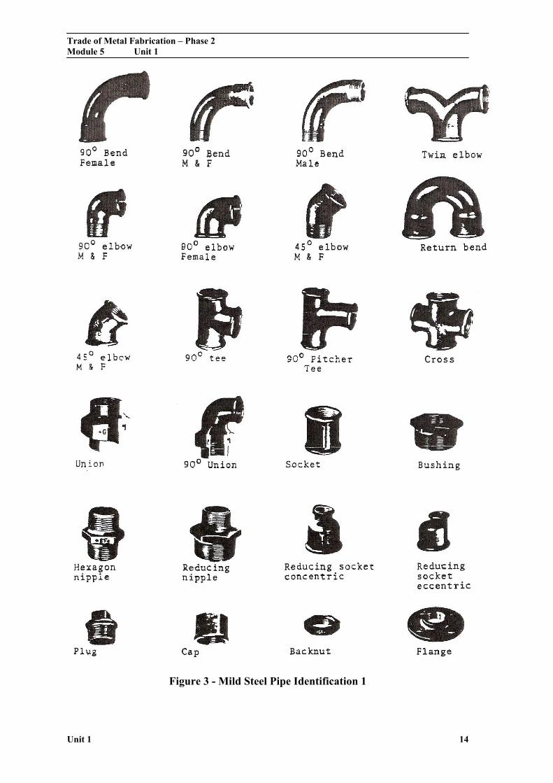
Mild Steel Pipe Identification
The threads on malleable iron pipe fittings are referred to as either male or female.
The male thread is the one where the threads are external and visible.
The female thread is the one where the threads are internal and hidden.
When ordering malleable iron tees with unequal outlets quote the size in the order shown in the figure opposite.
So the correct way to quote the tees piece shown is: 25mm x 15mm x 20mm.
The Z dimension is the distance from the centre of the fitting to the point reached by the end of the pipe when it has been screwed the proper distance into the fitting.
When piping runs are being prefabricated it is essential to know this dimension and it can be obtained from the fitting manufactures catalogue.
Trade of Metal Fabrication – Phase 2 Module 5 Unit 1
Unit 1 14
Figure 3 - Mild Steel Pipe Identification 1

Trade of Metal Fabrication – Phase 2 Module 5 Unit 1
Unit 1 15
Figure 4 - Mild Steel Pipe Identification 2

Trade of Metal Fabrication – Phase 2 Module 5 Unit 1
Unit 1 16
Mild steel piping is supplied in 6.4m lengths.
Finished in Black or hot dipped galvanised for extra corrosion resistance. These lengths can have either:
A. PLAIN ENDS: When they are to be welded together on site.
B. THREADED ENDS: When threaded joints are to be used on site. On threaded lengths, one socket is supplied with each length.
Mild steel pipes are sized by their internal diameters or bores and come in the following sizes, all in mm.
8, 10, 15, 20, 25, 32, 40, 50, 65, 80, 100, 150, 200 etc.
MEDIUM GRADE: Marked with blue band. Suitable for low pressure hot water heating and gas installations.
HEAVY GRADE: Marked with a red band. Suitable for steam and high temperature hot water heating installations.
SCHEDULE 40 & 80: The particular schedule is stamped on the outside of the pipe.
ACTUAL SIZE
Note: M.O.P No. = Maximum Operating Pressure.
Trade of Metal Fabrication – Phase 2 Module 5 Unit 1
Unit 1 17
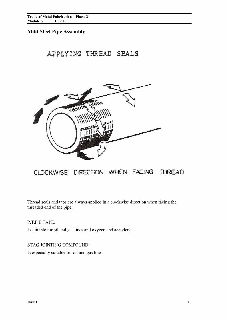
Mild Steel Pipe Assembly
Thread seals and taps are always applied in a clockwise direction when facing the threaded end of the pipe.
P.T.F.E TAPE:
Is suitable for oil and gas lines and oxygen and acetylene.
STAG JOINTING COMPOUND:
Is especially suitable for oil and gas lines.

Trade of Metal Fabrication – Phase 2 Module 5 Unit 1
Unit 1 18
Piping Fabrication and Erection
Piping Fabrication
The modern pipe fabrication shop requires that it be designed and organised to obtain a speedy flow of a large number of integral parts to finished complex assemblies. A typical fabrication shop is shown in Figure 5.
Figure 5 - General View of a Pipe Fabrication Shop

Trade of Metal Fabrication – Phase 2 Module 5 Unit 1
Unit 1 19
Fabrication Drawings
Prior to fabrication, workshop sketches or spools are prepared in the drawing office from either general arrangement drawings or isometrics. These sketches are simple and quickly prepared but are complete with all the necessary information to enable the pipes to be fabricated. The use of computerised isometrics is becoming widespread and is gradually replacing the hand-drawn isometric. The computerised isometric offers advantages to the pipework fabricator and some of these are:
(a) The flow of isometrics from drawing office to fabricator is continuous in quantity and allows better planning in the fabrication shop, enabling streamlined production by issue of workshop sketches in the right priority and batching of sketches into bore sizes to suit fabrication operations. With hand-drawn isometrics, the flow to the fabricator is invariably slow and batch production not always practicable.
(b) Material takeoff is accurate; therefore material hold-ups are more or less eliminated and at the end of the contract the problem of surplus or shortages of material seldom occurs.
(c) Errors in dimensions are largely eliminated and modifications to isometrics are few and far between, thus avoiding the disruption in production caused by errors and modifications, with resultant savings in costs and time.
Fabrication Specifications
These are highly important documents which are issued to the pipe fabricator's inspection department and to works' management and the standard laid down is strictly adhered to. Many purchasing companies issue their own standard specifications covering quality of workmanship and these all follow a similar pattern. The following typical specification gives an idea of the stringent control required during fabrication:
STANDARD SPECIFICATION No. SS-L5-1
FABRICATION OF PIPEWORK - CARBON STEEL AND CARBON ½ MOLY PIPEWORK TO USAS. B31.3
A. GENERAL
A.1. Purpose
The purpose of this standard specification is to define an acceptable standard for the fabrication of carbon steel and carbon ½ moly pipework to USAS B31.3, excluding large bore low pressure ducting and pipes to API 5LX specification.

Trade of Metal Fabrication – Phase 2 Module 5 Unit 1
Unit 1 20
Figure 6 - Pipebank being Hydraulic Tested in Test Bay

Trade of Metal Fabrication – Phase 2 Module 5 Unit 1
Unit 1 21
Mechanical and Structural Engineering
A good working knowledge is required of both subjects. Pipework in operation is always in movement and subjected to pressures and forces in itself with consequent reactions on mechanisms such as pumps, compressors and equipment generally and on structures, structural members and related pipework. Lack of knowledge can cause errors sufficient to cause machine or equipment breakdown, or to overstress and even cause collapse of structure.
Figure 7 - B.I.C.I.'s Olefines Plant at Wilton, Teeside
Capacity 450,000 tons of ethylene per year – the largest stream olefines plant in the world.

Trade of Metal Fabrication – Phase 2 Module 5 Unit 1
Unit 1 22
Figure 8 - Plate C. A Section of I.C.I.'s Olefines Plantat Wilton, Teeside

Trade of Metal Fabrication – Phase 2 Module 5 Unit 1
Unit 1 23
Colour Codes for the Contents of Pipes
British Standard 1710: 1971, which agrees with I.S.0./R 508, lays down the colour coding used to denote the contents of pipes. The use of a system of colour coding is most important as it enables the fitter to immediately locate a pipe carrying a particular service. The colour coding can appear on the pipes in one of the following three ways:
a) The whole pipe can be painted the correct colour.
b) Coloured bands can be painted around the pipe, over a length of about 150 mm.
c) Coloured sticky tape can be fastened around the pipe, over a length of about 150mm.
The table below gives the colour codes used for denoting the different contents of pipes:
Colour Contents
Green Water
Silver grey Steam
Brown Mineral, vegetable and animal oils, combustible liquids
Yellow ochre Gases in liquid or gaseous form (except air)
Light blue Air
Violet Acids and Alkalis
Black Other fluids
Orange Electrical services

Trade of Metal Fabrication – Phase 2 Module 5 Unit 1
Unit 1 24
Carbon Content in Steel
The effect that an increase of carbon would have on steel should be noted. As the percentage of carbon is increased, so is the tensile strength, toughness and hardness of the steel, but it also reduces ductility.
Practical Effect of the Variation in the Carbon Content of Steels in the Hardening and Tempering Operations
In the heat-treatment processes the percentage of carbon present in a stool is one of the important factors in determining the required process temperature and the resulting properties of the steel.
Hardening
For hardening, the temperature to which the steel should be heated varies according to the percentage of carbon present in the steel.
From pure iron which contains no carbon to steel containing 0.87% carbon this temperature decreases relatively slowly from approximately 950°C to 750°C.
The temperature rises steeply with an increasing carbon content above 0.87%, with an increased danger of brittleness and cracking.
Steels containing less than 0·3 % carbon cannot be hardened effectively, the maximum effect being obtained in steels having about 0.7% carbon content.
Tempering
Tempering is usually only carried out on high-carbon steels which have been subjected to a hardening process.
Low-carbon steels are not easily hardened and therefore tempering is not required.
Classification of Carbon Steels
Carbon steels are classified according to the percentage of carbon they contain. They are referred to as low, medium, high and very-high-carbon steels.
Low-Carbon Steel
Steels with a carbon range of 0.05 to 0.30 percent are called low-carbon steels. Steels in this class are tough, ductile and easily machined, formed and welded. Most of them do not respond to any heat treating process except case hardening. Low-carbon steel, when subjected to the spark test, will throw off long, white-coloured streamers with very little or no sparklers.

Trade of Metal Fabrication – Phase 2 Module 5 Unit 1
Unit 1 25
Medium-Carbon Steels
These steels have a carbon range from 0.30 to 0.45 percent. They are strong and hard but cannot be worked or welded as easily as low carbon steels. Because of their higher carbon content, they can be heat treated.
High and Very-High-Carbon Steels
Steels with a carbon range of 0.45% to 0.75% are classified as high-carbon and those with 0.75% to 1.7% carbon as very-high-carbon steels. Both of these steels respond well to heat treatment. As a rule, steels up to 0.65% carbon can be welded with special electrodes, although preheating and stress relieving techniques must often be used after the welding is completed.
Importance of Carbon in Steel
Carbon is the principal element controlling the structure and properties that might be expected from any carbon steel. The influence that carbon has in strengthening and hardening steel is dependent upon the amount of carbon present and upon its microstructure. Slowly cooled carbon steels have a relatively soft iron pearlitic microstructure; whereas rapidly quenched carbon steels have a strong, hard, brittle, martensitic microstructure.
Other Factors Altering Strength and Structure
When a metal is cold-worked (that is; hammered, rolled or drawn through a die) the ferrite and pearlite grains are made smaller and the metal becomes stronger and harder. If, after cold working, the metal is heated and allowed, to cool, the grain size is again increased and the metal softened.

Trade of Metal Fabrication – Phase 2 Module 5 Unit 1
Unit 1 26
Self Assessment
Questions on Background Notes – Module 5.Unit 1
No Suggested Questions and Answers.

Trade of Metal Fabrication – Phase 2 Module 5 Unit 1
Unit 1 27
Index
C Capacity, 9
Example 1, 10 Example 2, 10
Carbon Content in Steel, 24 Classification of Carbon Steels, 24 High and Very-High-Carbon Steels, 25 Importance of Carbon in Steel, 25 Low-Carbon Steel, 24 Medium-Carbon Steels, 25 Other Factors Altering Strength and Structure, 25 Practical Effect of the Variation in the Carbon Content of Steels in the Hardening and Tempering Operations, 24
Colour Codes for the Contents of Pipes, 23 Cross-Sectional Area, 8
M Mild Steel Pipe & Fittings, 10
Apprentice Plumbing, 11 Mild Steel Pipe Assembly, 17 Mild Steel Pipe Identification, 13
P Piping Fabrication
Fabrication Drawings, 19 Fabrication Specifications, 19
Piping Fabrication and Erection, 18 Mechanical and Structural Engineering, 21 Piping Fabrication, 18
Practical Effect of the Variation in the Carbon Content of Steels in the Hardening and Tempering Operations Hardening, 24 Tempering, 24
S Self Assessment, 26
V Volume of Metal, 9