Traceability Matrix
27
Traceability Matrix Exceed Doctor Software System Version: 2.0 Date: October 28, 2014
-
Upload
dmitry-kotleev -
Category
Documents
-
view
49 -
download
1
Transcript of Traceability Matrix

Traceability Matrix
Exceed Doctor Software System
Version: 2.0 Date: October 28, 2014

Document History and Distribution
1. Revision History
Revision # Revision Date
Description of Change Author
1.0 July 11, 2014 Preliminary draft Dmitry Kotleev
1.1 August 14, 2014
R&D review Michael Sidorenko
1.2 October 3, 2014
Sales & Marketing review Nir Danai
2.0 October 28, 2014
Final draft Vladimir Lucenko
2. Distribution
Recipient Name Recipient Organization Distribution Method
Dave Graver Great Lakes Orthodontics Email

Traceability Matrix
1f
Table of Contents
1. Introduction 2
1.1. Scope 2
1.2. Definitions, Acronyms, and Abbreviations 2
1.3. References 3
1.4. Functional Requirements Traceability Matrix 4

Traceability Matrix
2f
1. Introduction
1.1. Scope
This document shows the relationship between system requirements contains the testing procedures for the independent verification and validation (IV&V) of the Exceed Doctor Software system.
1.2. Definitions, Acronyms, and Abbreviations
Bracket/s (appliance/s) Small objects, typically made of metal, ceramic or composite, that are cemented onto the teeth to be used as anchorage points for the wires, as part of an orthodontic correction.
3D Model (model) 3D computer replica of the patient's teeth, produced by digitizing dental casts or impressions of the patient's mouth or by direct, intra-oral scanning. Refers to a specific order.
Data Exchange Server A computer used to store data about Orders and information exchange between EDS, DPO (see below) and the Exceed Center. The Data Exchange Server is part of Exceed Software System.
DPO Doctor's Personal Office - a web application allowing to upload patient records, submit, manage and track Orders. The DPO is part of Exceed Software System.
ECS Exceed Center Software System - the software used by Exceed Center employees to Rx and Tx Placement Plans. The ECS is part of Exceed Software System.
EDS Exceed Doctor Software System - the software used by the treating clinician to analyze, modify and approve Rx and Tx Placement Plans. The EDS is part of the Exceed Software System.
ES Exceed Software System - System formation, registration procurement and fulfillment of Orders for the production of bracketing trays
Exceed Center An office where employees are using the ECS to generate Rx and Tx Placement Plans.

Traceability Matrix
3f
Order/s (Case/s) Request for a virtual bracket placement plan and the subsequent production of bracketing trays. Each request is linked to a 3D-model of the patient's dentition.
Placement Modification/s (Modification/s)
Dr.-adjusted modification of the Placement Plan. Refers to a specific order. Each Placement Plan can be modified a few times.
Placement Plan/s (Plan/s) Layout of the brackets positioned on the patient's teeth, originally prepared by the Exceed Center. Refers to a specific order.
Rx Case Order of the Rx service
Rx Plan/s Mathematical calculation displaying the recommended positioning of Brackets on the patient's teeth, based on the pre-treatment 3D Model, the type of orthodontic brackets utilized, and the clinician's general pre-treatment bracketing preferences.
Rx Service Production of bracketing trays based on the Doctor-approved Rx Plan.
Scene 3D virtual space to display the 3D Model, as well as the Placement Plans.
Tx Case/s Order of a Tx service
Tx Plan/s A mathematical calculation of the recommended positioning of Brackets on the patient's malocclusion, based on dynamic tooth movement from the pre-treatment malocclusion to a desired post-treatment outcome. It is based on the pre-treatment 3D Model, the type of brackets utilized, the treatment plan prescribed by the clinician, the clinician's general post-treatment treatment preferences, as well as intra-oral images, facial photos and panoramic radiographs of the patient.
Tx Service Production of bracketing trays based on the doctor-approved Tx Plan.
Wire/s Ligament, typically made of metal or smart alloys that are attached to orthodontic brackets and are used to apply forces on the teeth, as part of an orthodontic correction.
1.3. References
Software Requirements Specification Document, version 2.0, dated May 29, 2014
Test Scenarios (Verification and Validation Document), version 2.0, dated September 17, 2014.
Hazard Analysis Document, version 2.0, dated October 14,2014

Traceability Matrix
4f
1.4. Functional Requirements Traceability Matrix
Require-ment #
Functional Requirement Description Test Case #
3.2.1 Internet and Data Exchange Server Connectivity
3.2.1.1 The system must perform the Internet connection availability check at startup.
1
3.2.1.2 The system should display connection status to the Internet at all times. 2, 3
3.2.1.3 The system should not allow the user to update the system, authorize, and perform actions that are only available to authorized users without an active connection to the Internet. The remaining functions of the system must be available at any state of connection to the Internet, active or inactive.
1, 2
3.2.1.4 User should be able to define parameters for connecting to the proxy server, if used.
1, 2
3.2.2 System Updating
3.2.2.1 Each time the system is started, connection should be established the Data Exchange Server to check for system updates.
4
3.2.2.2 Each time there is a change in Internet connection status, the system should connect to the Data Exchange Server and check for system updates.
4
3.2.2.3 If there is an update available, the system should prompt the user to download and install the update.
4
3.2.2.4 The user should be able to decline the prompt to download and install the update and instead, continue to work with the current version of the system.
4
3.2.2.5 With the consent of the user to upgrade, the system must implement and install the update.
4
3.2.3 Authorization
3.2.3.1 The system should allow users to log in. 5
3.2.3.2 Only authorized users should be able to view current list of Orders on the Data Exchange Server, downloading Orders from the server, approve Placement Plans and sending them back for revisions. Unauthorized users should be deprived of these features.
5, 6

Traceability Matrix
5f
Require-ment #
Functional Requirement Description Test Case #
3.2.3.3 The system should not allow the user to authorize without an active Internet connection.
1, 2
3.2.3.4 For authorized users, the system should display the name of the user account.
5
3.2.3.5 The system should allow the user to sign out and subsequently log in using a different account.
5
3.2.4 Processing Orders
3.2.4.1 Order Types
3.2.4.1.1 The system must perform the work with two types of orders: Rx Orders and Tx orders.
7
3.2.4.1.2 The system should be able to handle normal and demo orders, the latter type is designed to allow novice or unregistered users, a quick preview into the system's capabilities.
7
3.2.4.2 Order Contents
3.2.4.2.1 The system shall operate on the contents of the order in accordance with the data model described in Section 3.3.
8, 9
3.2.4.3 Order Lifecycle
3.2.4.3.1 The system must distinguish between the following order statuses:
The 3D model and the Placement Plans proposed by the Exceed Center;
Orders requiring attention of the clinician - orders which include new or revised Placement Plans, followed by approval or a revision request
Placement Plans Modifications performed by the clinician;
Placement Plans revision requests communicated to the Exceed Center.
6, 10
3.2.4.3.2 When the 3D model and the Placement Plan are in the process of preparation by the Exceed Center, the Order should not be available for download from the server.
7
3.2.4.3.3 Orders requiring the attention of the clinician should be available to download from the server for the purpose of Placement Plan Modification, Placement Plan approval or Placement Plan revision request.
8, 9
3.2.4.4 Working with Orders' Lists
Traceability Matrix
6f
Require-ment #
Functional Requirement Description Test Case #
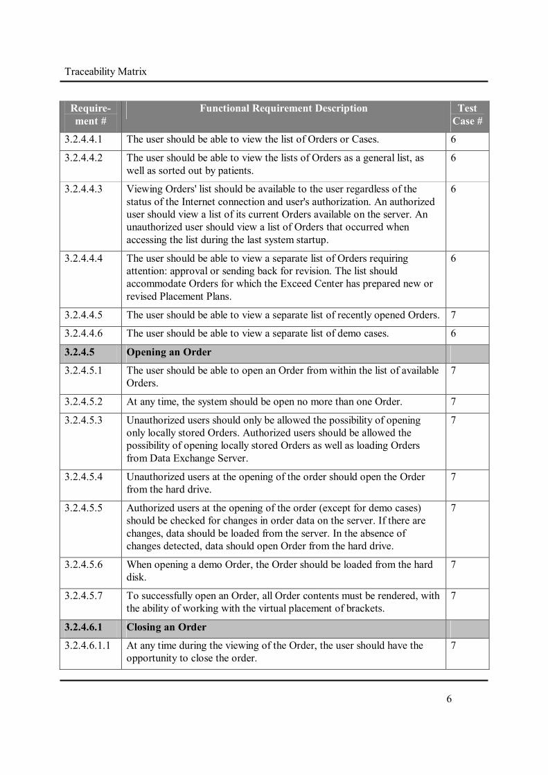
3.2.4.4.1 The user should be able to view the list of Orders or Cases. 6
3.2.4.4.2 The user should be able to view the lists of Orders as a general list, as well as sorted out by patients.
6
3.2.4.4.3 Viewing Orders' list should be available to the user regardless of the status of the Internet connection and user's authorization. An authorized user should view a list of its current Orders available on the server. An unauthorized user should view a list of Orders that occurred when accessing the list during the last system startup.
6
3.2.4.4.4 The user should be able to view a separate list of Orders requiring attention: approval or sending back for revision. The list should accommodate Orders for which the Exceed Center has prepared new or revised Placement Plans.
6
3.2.4.4.5 The user should be able to view a separate list of recently opened Orders. 7
3.2.4.4.6 The user should be able to view a separate list of demo cases. 6
3.2.4.5 Opening an Order
3.2.4.5.1 The user should be able to open an Order from within the list of available Orders.
7
3.2.4.5.2 At any time, the system should be open no more than one Order. 7
3.2.4.5.3 Unauthorized users should only be allowed the possibility of opening only locally stored Orders. Authorized users should be allowed the possibility of opening locally stored Orders as well as loading Orders from Data Exchange Server.
7
3.2.4.5.4 Unauthorized users at the opening of the order should open the Order from the hard drive.
7
3.2.4.5.5 Authorized users at the opening of the order (except for demo cases) should be checked for changes in order data on the server. If there are changes, data should be loaded from the server. In the absence of changes detected, data should open Order from the hard drive.
7
3.2.4.5.6 When opening a demo Order, the Order should be loaded from the hard disk.
7
3.2.4.5.7 To successfully open an Order, all Order contents must be rendered, with the ability of working with the virtual placement of brackets.
7
3.2.4.6.1 Closing an Order
3.2.4.6.1.1 At any time during the viewing of the Order, the user should have the opportunity to close the order.
7

Traceability Matrix
7f
Require-ment #
Functional Requirement Description Test Case #
3.2.4.6.1.2 Prior to closing the Order and in the presence of unsaved changes, system should provide an alert of the situation and request confirmation of the need to complete the work without saving changes.
10
3.2.4.7 Local Storage of Orders
3.2.4.7.1 Each time Order data is reload from the server, the order must be maintained locally.
7
3.2.4.7.2 All demo cases must be stored locally. 7
3.2.4.7.3 Locally saved Orders must be able to open for both authorized and unauthorized users.
7
3.2.4.7.4 The user should be able to adjust the path to the directory for local storage of Orders.
7
3.2.4.7.1 Opening Cases From a Hard Drive
3.2.4.7.1.1 When trying to open a local Order copy that is not stored locally, the system should display an appropriate message.
7
3.2.4.7.2 Saving Cases to a Hard Drive
3.2.4.7.2.1 When working with the contents of the Order, user should have the opportunity at all times to locally save all changes made.
10
3.2.4.8 Server Storage Requirements
3.2.4.8.1 Communication with Data Exchange Server should be available to authorized users only.
2
3.2.4.8.2 The system should not allow users to communicate with the Data Exchange Server without an active Internet connection.
7, 10
3.2.4.8.2 The amount of data transferred between the Data Exchange Server and EDS, should be minimized: sender must only transmit data that is missing from the recipient (new Placement Plans, Placement Plans modifications, new data on the positioning of brackets, new types of bracket data etc.).
3.2.4.8.4 Local changes in Orders without uploading to a server or should lead to out of sync data between the server and the EDS Order. Data transfer between the server and EDS should lead to data synchronization upon request.
10
3.2.4.8.5 Indicator of synchronization between the server and EDS should be set separately for each 3D model, Placement Plan and Placement Plan modification. Must be a valid situation where some 3D models, Placement Plans, Placement Plans modifications, are synchronized, and some are not.
10

Traceability Matrix
8f
Require-ment #
Functional Requirement Description Test Case #
3.2.4.8.6 The user should see the status indicator synchronization for each 3D model, Placement Plan and Placement Plan modification.
10
3.2.4.8.7 Exchange of data with the server when demo cases are concerned should not take place.
10
3.2.4.8.1 Downloading Cases From Server
3.2.4.8.1.1 Loading data on request from the server must be carried out only if the data are available on the server and in the absence of locally stored data (for example, a new Placement Plan).
10
3.2.4.8.1.2 If the Order is not stored locally, upon loading, the system must load order data completely. If a local copy of the Order exists, the system should proceed by creating a local copy of the new data received from the server (to make data integration).
3.2.4.8.1.3 A successful loading from the server is completed when the Order or Order update are maintained locally over a local copy of the previous Order.
10
3.2.4.8.1.4 A successful loading from the server to the loaded 3D models, Placement plans and Placement Plan Modifications must display a synchronization sign.
10
3.2.4.8.1.5 When downloading from the server has been unsuccessful, the system should display an appropriate message, including an inactive status of the Internet connection.
3.2.4.8.2 Uploading changes to server
3.2.4.8.2.1 Uploading data to the server should be done in case a Placement Plan has been approved, sent back for revisions, or self-modified.
10
3.2.4.8.2.2 Prior to loading, the server should have local data storage order.
3.2.4.8.2.3 Following a successful upload to the server of the downloaded models, a synchronization sign must be displayed.
10
3.2.4.8.2.4 When downloading to the server system has been unsuccessful, an appropriate message should be displayed, including an inactive status of the Internet connection.
10
3.2.5 Positioning Brackets
3.2.5.1 General Requirements for Working with 3D Models, Placement Plans and Placement Plans Modifications
3.2.5.1.1 Using the 3D Model and the Placement Plans must be available to the user only after opening the Order.
8, 9

Traceability Matrix
9f
Require-ment #
Functional Requirement Description Test Case #
3.2.5.1.2 The Order must maintain information about each 3D model, Placement Plan and Placement Plan Modifications. Deleting data entities when dealing with orders at the EDS should not be available.
8, 9
3.2.5.1.3 Upon selecting an Order, all associated 3D models, Placement Plans and Placement Plan Modifications, including names and numbers shall be displayed.
8, 9
3.2.5.1.4 Within the Order, the user should be able to select one or more of the 3D models, Placement Plans and/or Placement Plans Modifications and visually compare them.
12
3.2.5.1.5 When working with an Order, the user must be able to make modifications only with the aim of ultimately approving the Placement Plan in question, or any modifications thereof. When working with a demo Order, the user should be able to make a modification in any way.
8, 9
3.2.5.1.6 The user should not be able to modify the 3D Model. 8, 9
3.2.5.1.7 A Placement Plan Modification should be created automatically every time a user attempts to edit a Plan requiring approval.
8, 9
3.2.5.1.8 The user must be able to clearly indicate the need to revise a Placement Plan.
8, 9
3.2.5.1.9 Only a Placement Plan proposed by the Exceed Center can be modified. The user will not be able to modify an already modified Placement Plan.
8, 9
3.2.5.2 Modes of Operation with the Placement of Brackets
3.2.5.2.1 Working with placement of brackets can be conducted in one of two modes:
"Edit" mode - the user only edits the Placement Plan;
"Animation" mode - the user only views an animated visualization of moving teeth and brackets from pre- to post-treatment.
11
3.2.5.2.2 When working with Rx Placement Plan, the system should operate only on "Edit" mode.
11
3.2.5.2.3 When working with Tx Placement Plan, the system will allow the user to switch between "Edit" and "Animation" modes.
11

Traceability Matrix
10f
Require-ment #
Functional Requirement Description Test Case #
3.2.5.3 Visualization of the 3D Model and the Placement Plan
3.2.5.3.1 General requirements for the visualization of three-dimensional scenes
3.2.5.3.1.1 When working with Rx Placement Plan, "Edit" mode, changes should show the position of brackets on the patient's teeth in the 3D Model, pre-treatment.
11
3.2.5.3.1.2 When working with Tx Placement Plan, "Edit" mode, changes should show the position of brackets on the patient's teeth in the 3D model, post-treatment.
11
3.2.5.3.1.3 When working with Tx-plan, "Edit" mode, the user should be able to see the position of the teeth and the brackets on the 3D model, pre- as well as post-treatment.
11
3.2.5.3.1.4 The system should have the ability to display multiple 3D Scenes for simultaneous viewing of user-selected 3D models, Placement Plans and Placement Plans Modifications. To display a 3D Scene, each system must have a separate rectangular area of the screen.
12
3.2.5.3.1.5 For each 3D scene, the system must clearly establish the appropriate 3D Model that defines the shape of the jaws and teeth as well as:
When the visualization model should be built on the basis of this model.
When the Placement Plan should be based on the visualization model associated with the said Placement Plan.
When the Placement Plan Modifications should be based on the visualization model associated with the modified Placement Plan.
3.2.5.3.1.6 For each 3D Scene, the system shall uniquely identify the position of the brackets (and when working with a Tx Placement Plan – also the dental arches):
When model brackets are not displayed.
When the Placement Plan is determined by the positioning of the brackets
When the Placement Plan Modification is determined by the modified positioning of the brackets.

Traceability Matrix
11f
Require-ment #
Functional Requirement Description Test Case #
3.2.5.3.2 Visualization Models, Plans and Modifications of the Model
3.2.5.3.2.1 The system should display a single, 3D Scene selected by the user for each 3D Model, Placement Plan and Placement Plan Modification. The choice of model may be necessary for the user to view the original orthodontic condition of the patient prior to treatment and placing brackets.
12
3.2.5.3.2.2 The system must provide the ability to display multiple 3D Scenes - one for each 3D Model, Placement Plan or modified Placement Plan selected by the user, to enable their visual comparison.
12
3.2.5.3.3 Displaying 3D Scenes
3.2.5.3.3.1 The user must be able to switch at any time between successive projections of 3D Scenes to display:
Front view;
Rear view;
Left side view;
Right side view.
12
3.2.5.3.3.2 When the only one of the jaws is selected for display (upper or lower), an occlusal view of the same jaw must be made available.
13
3.2.5.3.3.3 When switching between available, multiple displays of the 3D scenes, all views should be centered with respect to the viewpoint.
12
3.2.5.3.3.4 The user should be allowed to move relative to the scene viewpoint. 12
3.2.5.3.3.5 The user should be allowed to freely rotate relative to the scene viewpoint.
12
3.2.5.3.3.6 The user should be allowed to freely zoom in and out of the Scene with respect to the viewpoint (perform scaling).
12
3.2.5.3.3.7 When displaying multiple models, Placement Plans or Placement Plans Modifications (a few three-dimensional scenes, see. Section 3.2.5.3.2), the user should be allowed to perform all movements and change projections simultaneously for all scenes displayed. This feature should help the user to perform a visual comparison of selected 3D Models, Placement Plans or Placement Plan Modifications.
12
3.2.5.3.4 Visualization of Arches
3.2.5.3.4.1 Visualization of the arches should be performed when working with both 3D models, Placement Plans and Placement Plans Modifications.
13

Traceability Matrix
12f
Require-ment #
Functional Requirement Description Test Case #
3.2.5.3.4.2 At the request of the user, the system should display within the 3D Scene, separate upper arch (lower hide), separately lower arch (upper hide) or both arches together.
13
3.2.5.3.4.3 At the request of the user, the system should display two separate 3D Scenes: one - for the upper jaw, the other - for the lower jaw.
13
3.2.5.3.4.4 The user should be able to select the joint arrangement of 3D Scenes to display separately the upper and lower arches using the following templates:
Scene 1 - on top of the other - from the bottom;
Scene 2 - on the left, the other - on the right.
13
3.2.5.3.4.5 A separate display of 3D Scenes for the upper and lower arches should be available in the case of a simultaneous display of multiple 3D Models/ Placement Plans / Placement Plan Modifications (see. Section 3.2.5.3.2). In this case, each selected view should be displayed in two stages - one for the upper arch and the other – for the lower.
13
3.2.5.3.5 Visualization of Teeth
3.2.5.3.5.1 Visualization of teeth must be performed when working with pre- and post-treatment 3D models, Placement Plans and Placement Plan Modifications.
11
3.2.5.3.5.2 When working with Rx Placement plan, the system should display the initial position of the teeth, pre-treatment.
11
3.2.5.3.5.3 When working with a Tx Placement plan, "Edit" mode, the system should display the final position of the teeth, post-treatment.
11
3.2.5.3.5.4 When working with a Tx Placement Plan, "Animation" mode, the system should display the position of the teeth pre-treatment and the, gradually progress to show the post-treatment position.
11
3.2.5.3.5.5 When working with a Tx Placement Plan (all modes), the system must make it visually noticeable to the user to display zone/s of teeth intersections, when available (a condition where one tooth collides within another).
17
3.2.5.3.6 Visualization of Brackets
3.2.5.3.6.1 Visualization of brackets should work with Placement Plans and Placement Plan Modifications, but not with the 3D Models.
11

Traceability Matrix
13f
Require-ment #
Functional Requirement Description Test Case #
3.2.5.3.6.2 A bracket must be rendered in accordance with its type, i.e. EDS visualizes selected brackets. Data for visualization is obtained from bracket CAD files (provided directly by the brackets' vendors or through 3D scanning of the said brackets.
3.2.5.3.6.3 When working with a Rx Placement Plan, the system should present the position of the brackets on the teeth, pre-treatment.
11
3.2.5.3.6.4 When working with a Tx Placement Plan, "Edit" mode, the system should display the position of the brackets on the teeth, pre- and post-treatment.
11
3.2.5.3.6.5 When working with a Tx Placement Plan, "Animation" mode, the system should display the movement of brackets and teeth from the initial, pre-treatment position until the final, post-treatment position. The trajectory of the teeth and brackets calculated when creating a Tx Placement Plan is for presentation purposes only. The EDS does not show and does not pretend to predict the true trajectory of the teeth.
11
3.2.5.3.6.6 The system must produce visually noticeable alerts to the user, at the time when position of the brackets is conceived as erroneous and as such, requires user attention. Instances that call for increased attention can be the following:
A bracket intersects with an adjacent or opposing tooth;
A brackets collides with the gingival tissue.
A bracket is positioned too far from the tooth crown (>1.5 mm).
15, 17, 18
3.2.5.3.6.7 When brackets' positioning is deemed as incorrect, the system should provide the user a written explanation - what seems to be the perceived problem.
15, 17, 18
3.2.5.3.6.8 The user should be able to toggle between hiding and showing brackets for both arches simultaneously.
13
3.2.5.3.7 Visualization of Wires
3.2.5.3.7.1 The Wires should be displayed only when working with a Tx Placement plan. The Wires are presented in natural size. EDS produces the visualization of only the final Wire prescribed by clinician to treat the patient.
11
3.2.5.3.7.2 Visualization of Wires should work with Placement Plans and Placement Plan Modifications, but not with the 3D Models.
11
3.2.5.3.7.3 The system should display the final position of the Wire, post-treatment. 11

Traceability Matrix
14f
Require-ment #
Functional Requirement Description Test Case #
3.2.5.3.7.4 The user should be able to toggle between hiding and showing Wires for both arches simultaneously.
13
3.2.5.3.8 Visualization of Occlusogram
3.2.5.3.8.1 The system shall, at the request of the user, display an occlusogram (a color chart depicting the distance in mm between the upper and lower arches).
14
3.2.5.3.8.2 The occlusogram should be displayed to the user at any projections. 14
3.2.5.3.8.3 The occlusogram displays gradations of color surfaces of the teeth, where each shade corresponds with a positive (if teeth are spaced apart from each other) or negative (if teeth interfere with each other) distance between the teeth.
14
3.2.5.3.8.4 In the occlusogram, there are designated colors displayed on all tooth portions, where distances to other teeth range from -0.2 to 1.2 mm. Other portions of the teeth surface not falling within that range are to be displayed in the usual color of the tooth.
14
3.2.5.3.9 Visualization of Teeth and Brackets Animation
3.2.5.3.9.1 Animation movements should only be available only when working with Tx Placement Plans.
11
3.2.5.3.9.2 Animation visualization should be available with Tx Placement Plans and Tx Placement Plan Modifications, but not with 3D Models.
11
3.2.5.3.9.3 When using the animation, the user should not be able to make any changes to the current Placement Plan or Placement Plan Modification. When attempting to modify the current Plan, the system should display an appropriate message.
11
3.2.5.3.9.4 When in the "Animation" mode, the user must be able to view the movement dynamics of brackets and teeth, from pre- to post-treatment.
11
3.2.5.3.9.5 The user should be able to run the animation playback movements. 11
3.2.5.3.9.6 The user should be able to pause the animation. 11
3.2.5.3.9.7 The user should be able to choose to render a particular time from the start of treatment until the end of treatment.
11

Traceability Matrix
15f
Require-ment #
Functional Requirement Description Test Case #
3.2.5.4 Selection of Elements in 3D Scenes
3.2.5.4.1 In the "Edit" mode, the user must be able to distinguish between the following elements, comprising the 3D Scene:
Tooth;
Bracket;
Wire.
15, 17, 18
3.2.5.4.2 The user must be able to select only one object at a time. Simultaneous selection of multiple elements should not be available.
15, 17, 18
3.2.5.4.1 Tooth selection
3.2.5.4.1.1 Selection of the tooth must be made by left-clicking on the image of the tooth (but not bracket) in the 3D Scene.
15, 17
3.2.5.4.1.2 When a tooth is selected, it should be highlighted. 15, 17
3.2.5.4.1.3 When a tooth is selected, the ADA tooth number should appear in a separate panel.
15, 17
3.2.5.4.1.4 When a tooth is selected, a heat map showing the distances between the bracket mounted on that tooth and the tooth should appear in a separate panel.
15, 17
3.2.5.4.1.5 When a tooth is selected, when working with a Tx Placement Plan or Tx Placement Plan Modification, a separate panel should display information about all the movements of that tooth.
17
3.2.5.4.1.6 When a tooth is selected, when working with a Tx Placement Plan Modification, controls should be displayed for managing its movement (rotation, extrusion, intrusion, mesial-distal body movement, in-out body movement, angulation, torque adjustment).
17
3.2.5.4.2 Appliance selection
3.2.5.4.2.1 Selection of brackets must be done by left-clicking on the image of the bracket in the 3D Scene.
15, 18
3.2.5.4.2.2 When a bracket is selected, the bracket should be highlighted. 15, 18
3.2.5.4.2.3 When a bracket is selected, a separate panel should display information about the selected bracket.
15, 18
3.2.5.4.2.4 When a bracket is selected, a separate panel should display the number of the bracket.
15, 18

Traceability Matrix
16f
Require-ment #
Functional Requirement Description Test Case #
3.2.5.4.2.5 When a bracket is selected, a heat map showing the distances between the said bracket and tooth on which the said bracket is mounted, should be displayed in a separate panel.
15, 18
3.2.5.4.2.6 When a bracket is selected, a view showing the positioning of the bracket relative to the tooth from the occlusal view should be displayed on a separate panel.
15, 18
3.2.5.4.2.7 When a bracket is selected, when working with a Rx Placement Plan Modification, controls should be displayed for managing its movement on the tooth surface (pressing to the tooth surface, rotation and panning).
16, 18
3.2.5.4.2.8 When a bracket is selected, when working with a Tx Placement Plan Modifications, controls should be made visible for managing mesial-distal movement.
18
3.2.5.4.3 Wire selection
3.2.5.4.3.1 Selection of Wires should not be made available 19
3.2.5.5 Tools for Visual Anlalysis for Recommended Bracket Positioning в
3.2.5.5.1 Heat Map Distances Between Brackets and Teeth
3.2.5.5.1.1 When a tooth or the corresponding bracket are selected, a separate panel should display the heat map distances between the brackets and teeth showing how the bracket is mounted on the tooth in different parts of the contact zone.
15, 17
3.2.5.5.1.2 The said heat map shall display front tooth projection and the contact area of the bracket to the tooth.
15, 17, 18
3.2.5.5.1.3 The contact area must be colored with shades: the color of each point of the zone should display the distance between the tooth and the bracket at an given point.
15, 18
3.2.5.5.1.4 Varying shades should cover the distance range from -1.0 mm (bracket-tooth interference) to 1.5 mm (bracket-tooth too distant).
15, 17, 18
3.2.5.5.2 Displaying Bracket Positioning Relative to the Tooth
3.2.5.5.2.1 When a tooth or the corresponding bracket are selected, a separate panel should display the bracket mounted on the tooth from an occlusal perspective, enabling visual analysis of the position of the bracket relative to the tooth.
15, 18
3.2.5.5.3 Displaying Bracket Information
3.2.5.5.3.1 When a bracket is selected, a separate panel should display information about the bracket.
15, 18

Traceability Matrix
17f
Require-ment #
Functional Requirement Description Test Case #
3.2.5.5.3.2 Information about the bracket should include the bracket catalog number, provided by the bracket vendor.
15, 18
3.2.5.5.3.3 In case bracket positioning is deemed erroneous, information on the positioning of the bracket should also include a description of the cause of the perceived error.
15, 18
3.2.5.5.4 Displaying Tooth Information
3.2.5.5.4.1 When a tooth or a bracket are selected, a separate panel should display the ADA number of the tooth.
15, 17
3.2.5.5.5 Displaying Information about the Movement of a Particular Tooth
3.2.5.5.5.1 When a tooth is selected, a separate panel should display numerical information about the movements of the selected tooth from the initial position to the final. This information is required by the user to determine the clinical feasibility of moving the tooth given the state of the patient's bone.
20
3.2.5.5.5.2 Information on the movement of the selected tooth should be displayed only when working with a Tx Placement Plan or a Tx Placement Plan Modification.
20
3.2.5.5.5.3 Information on the movement of the tooth should include the following:
Rotation angle in degrees;
Angulation angle in degrees;
Inclination angle in degrees;
In/out shift in mm;
Extrusion/ intrusion shift in mm;
Mesial/distal shift in mm.
20
3.2.5.5.5.4 When the pre-treatment 3D Model is displayed (not the Tx Placement Plan or Tx Placement Plan Modification) zero values should appear for all movement parameters.
20
3.2.5.5.6 Displaying Information on Teeth Movement
3.2.5.5.6.1 When working with a Tx Placement Plan or Placement Plan Modification, the user should be able to view a table indicating the different moves from the initial position to the final for all teeth. This information is required by the user to determine the clinical feasibility of moving the teeth given the state of the patient's bone.
20

Traceability Matrix
18f
Require-ment #
Functional Requirement Description Test Case #
3.2.5.5.6.2 A table presenting such data should include the following numerical values of the parameters for each tooth:
Rotation angle in degrees;
Angulation angle in degrees;
Inclination angle in degrees;
In/out shift in mm;
Extrusion/intrusion shift in mm;
Mesial/distal shift in mm.
20
3.2.5.5.6.3 When the pre-treatment 3D Model is displayed (not the Tx Placement Plan or Tx Placement Plan Modification) zero values should appear for all movement parameters.
20
3.2.5.6 Measuring Tools
3.2.5.6.1 Use of measuring tools shall not in any way affect the position of teeth, brackets, or Wires.
21
3.2.5.6.1 Measuring Teeth Width
3.2.5.6.1.1 The user should be able to measure the width of each individual tooth. 21
3.2.5.6.1.2 The width of the tooth should be calculated as the distance between the two extremes of the tooth.
21
3.2.5.6.1.3 The user must be able to designate the extreme points of any tooth on any location in that tooth.
21
3.2.5.6.1.4 After that, for each tooth, the system should visually display the endpoints connecting their line and length of line in millimeters.
21
3.2.5.6.1.5 The user will be able to modify the extreme points of the teeth by redrawing of points, lines and counting distances.
21
3.2.5.6.2 Measuring Arch Length
3.2.5.6.2.1 The user should be able to measure the desired arch length separately for each jaw.
21
3.2.5.6.2.2 The length of each arc should be calculated as the total distance between the nodal points of the arch.
21
3.2.5.6.2.3 The user should be able to shift the nodal point of the arch on the occlusal plane, thereby changing the intended curvature of the arc.
21
3.2.5.6.2.4 The system must visually display the resulting arc of its nodal points and the total distance in millimeters.
21

Traceability Matrix
19f
Require-ment #
Functional Requirement Description Test Case #
3.2.5.6.2.5 By moving the user node points, new measurement should be made by redrawing points, arcs and counting the total distance.
21
3.2.5.6.2.6 Moving the nodal points of the arch should only affect measurement results and will not impact the final form taken by the arch, post-treatment.
3.2.5.6.3 Measuring Arch Width
3.2.5.6.3.1 The user should be able to measure the width of the arch in defined areas, separately for each jaw.
21
3.2.5.6.3.2 For the purposes of measuring arch width the system must visually display:
three auxiliary lines arranged in a plane arch, to measure the width of the arch in designated locations;
a fourth auxiliary line, also located in a plane perpendicular to the arch and the third line, for measuring the distance between the third line and the central point of the arch at the point of inflection.
21
3.2.5.6.3.3 Prior to starting the measurement, lines should be located by default as follows:
The first three lines are parallel to each other;
The end of the fourth line should be placed at the center point of inflection in the place of the arch;
Distances between the first three lines must be equal.
21
3.2.5.6.3.4 The user must be able to freely move the ends of the first three lines of the arch on the occlusal plane, so that they cannot be provided parallel to each other. In the fourth line, the user must be able to move only one of its ends, the second end has to be automatically positioned on the third line so that the third and fourth lines are always perpendicular.
21
3.2.5.6.4 Measuring Cross Section
3.2.5.6.4.1 The user must be able to measure the distance in the vertical cross section plane perpendicular to the frontal plane of the oral cavity, along lines perpendicular to the frontal plane. In particular, the user must be able to measure the size of the sagittal fissure.
21
Traceability Matrix
20f
Require-ment #
Functional Requirement Description Test Case #
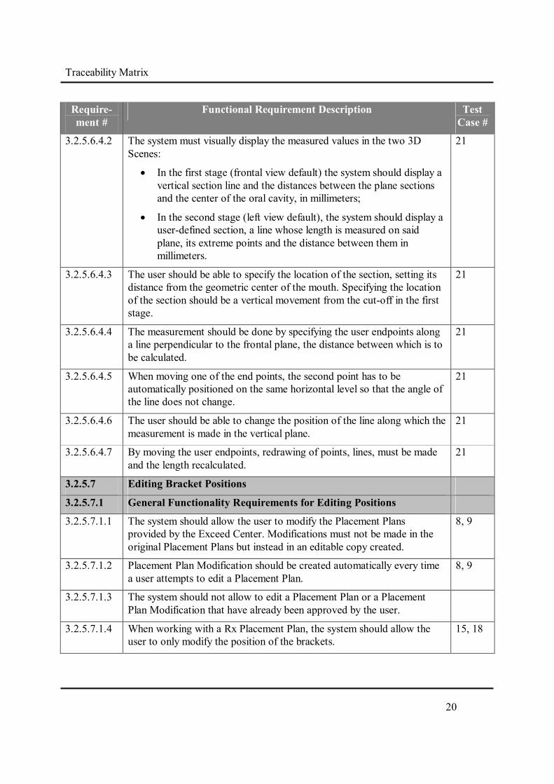
3.2.5.6.4.2 The system must visually display the measured values in the two 3D Scenes:
In the first stage (frontal view default) the system should display a vertical section line and the distances between the plane sections and the center of the oral cavity, in millimeters;
In the second stage (left view default), the system should display a user-defined section, a line whose length is measured on said plane, its extreme points and the distance between them in millimeters.
21
3.2.5.6.4.3 The user should be able to specify the location of the section, setting its distance from the geometric center of the mouth. Specifying the location of the section should be a vertical movement from the cut-off in the first stage.
21
3.2.5.6.4.4 The measurement should be done by specifying the user endpoints along a line perpendicular to the frontal plane, the distance between which is to be calculated.
21
3.2.5.6.4.5 When moving one of the end points, the second point has to be automatically positioned on the same horizontal level so that the angle of the line does not change.
21
3.2.5.6.4.6 The user should be able to change the position of the line along which the measurement is made in the vertical plane.
21
3.2.5.6.4.7 By moving the user endpoints, redrawing of points, lines, must be made and the length recalculated.
21
3.2.5.7 Editing Bracket Positions
3.2.5.7.1 General Functionality Requirements for Editing Positions
3.2.5.7.1.1 The system should allow the user to modify the Placement Plans provided by the Exceed Center. Modifications must not be made in the original Placement Plans but instead in an editable copy created.
8, 9
3.2.5.7.1.2 Placement Plan Modification should be created automatically every time a user attempts to edit a Placement Plan.
8, 9
3.2.5.7.1.3 The system should not allow to edit a Placement Plan or a Placement Plan Modification that have already been approved by the user.
3.2.5.7.1.4 When working with a Rx Placement Plan, the system should allow the user to only modify the position of the brackets.
15, 18

Traceability Matrix
21f
Require-ment #
Functional Requirement Description Test Case #
3.2.5.7.1.5 When working with a Tx Placement Plan, system should allow the user to modify the position of brackets (in the mesio-distal plane only), teeth and wires.
17, 18, 19
3.2.5.7.1.6 When working with a Tx Placement Plan, a modification in the position of brackets and teeth should be construed as a modification to the final position of brackets and teeth.
17, 18
3.2.5.7.1.7 When working with a Tx Placement Plan for the final position of the teeth and brackets (user-defined) as well as the initial position of the teeth (in the original 3D Model), the initial position of the brackets should be automatically calculated.
17, 18
3.2.5.7.1.8 When working with a Tx Placement Plan, a modification of the position of the wire should be construed as a change in the final position of the wire, which should lead to a change in the final position of the brackets attached to the wire.
3.2.5.7.1.9 When working with a Tx Placement Plan, the system should provide the ability to modify only in "Edit" mode. When trying to change position of elements in "Animation" mode, the system should display an appropriate message.
11
3.2.5.7.1.10 In the course of moving the brackets and teeth, the system must dynamically and continuously redraw them in accordance with the requirements of Visualization of brackets and teeth: allocate the intersection of teeth, identify incorrect position of brackets, etc.
15, 18
3.2.5.7.1.11 The system should allow the user to undo any modifications to the movements of brackets, teeth and wires.
15, 17, 18, 19
3.2.5.7.2 Modifying Bracket Position When Working With a Rx Placement Plan
3.2.5.7.2.1 When working with an Rx Placement Plan, any modifications concern the position of the brackets relative to the teeth.
3.2.5.7.2.2 When working with and Rx Placement Plan, the system should allow the user to perform a calculation of the recommended position of the bracket on the tooth (auto-installed).
16
3.2.5.7.2.3 Calculation of the recommended position of the bracket on a tooth should be based on the shape of the tooth, the geometry of the bracket and the calculation method that best fits the general preferences of the clinician in placing brackets pre-treatment.
3.2.5.7.2.4 The system should allow the user to select the desired method of calculation.
16

Traceability Matrix
22f
Require-ment #
Functional Requirement Description Test Case #
3.2.5.7.2.5 The system should allow a user to move the bracket on the surface of the tooth.
15
3.2.5.7.2.6 When moving a bracket on the tooth, the bracket should maintain maximum contact points with the tooth surface.
15
3.2.5.7.2.7 The system should allow a user using a computer mouse to indicate which side of the bracket center has to be pressed to achieve maximum contact with the tooth surface.
16
3.2.5.7.2.8 The system should provide the user with the ability to rotate the bracket with respect to its axis perpendicular to the tooth surface.
16
3.2.5.7.2.9 When a bracket is moved, the information displayed in the visual analysis tools for the position of the brackets will also be updated.
15, 18
3.2.5.7.3 Modifying Bracket Positions When Working with a Tx Placement Plan
3.2.5.7.3.1 When working with a Tx Placement Plan, any change in the position of the brackets should be construed as a change in the position of the brackets relative to the tooth crown.
18
3.2.5.7.3.2 A change in the position of brackets can only be made on the position of the teeth post treatment. The system must automatically recalculate the position of the brackets on the basis of the final position of the teeth (user-defined) on the teeth in the initial 3D Model, pre-treatment.
18
3.2.5.7.3.3 The system should provide the user with the following options for moving a bracket:
Move the bracket together with the tooth (tooth moves after the bracket);
Move the bracket independently from the tooth (tooth remains in place).
18
3.2.5.7.3.4 Moving the bracket should always be limited to mesio-distal drifting along the wire plane.
18
3.2.5.7.3.5 When a bracket is moved, the information displayed in the visual analysis tools for the position of the brackets will also be updated.
18
3.2.5.7.4 Modifying Teeth Positions When Working with a Tx Placement Plan
3.2.5.7.4.1 Modifying teeth position should be enabled only when working with a Tx Placement plan.
15, 17

Traceability Matrix
23f
Require-ment #
Functional Requirement Description Test Case #
3.2.5.7.4.2 When working with a Tx Placement Plan, any modification to the position of the teeth should be construed as a change in the final position of the teeth.
17
3.2.5.7.4.3 Modifying the position of the teeth should lead to a re-calculation of the position of the brackets on the basis of the final position of brackets and the initial position of the teeth on the 3D Model.
17
3.2.5.7.4.4 When modifying teeth position, the corresponding brackets should not move.
17
3.2.5.7.4.5 The system should provide the user with two models for tooth movement:
Mode 1 - Along the wire plan;
Mode 2 - Free spatial movement.
17
3.2.5.7.4.6 "Free movement" mode should be carried out by moving the tooth mouse and using appropriate guides. The user will not be able to modify change the numerical parameters responsible for tooth position.
17
3.2.5.7.4.7 When working in any plane (facial, occlusion, etc.) in "Free movement" mode, the user should be allowed to grab the mouse and drag the tooth, thereby moving it in the plane to a new position.
17
3.2.5.7.4.8 Tooth movement guides should display when the tooth is selected. 17
3.2.5.7.4.9 With the exception of the occlusal projection, when working in all other projection (front, left, etc.), in the "Free movement" mode, the following visual guides shall be displayed:
a point lying on the edge of the tooth root – located on the intersection of the root axis and the gingival edge;
handle/s for modifying the angle of the tooth, allowing the tooth to angulate in the current projection plane around a specified point (the edge of the tooth root remains fixed);
handle/s for moving the tooth up and down along the root axis, allowing tooth extrusion/intrusion.
17
3.2.5.7.4.10 When working in the occlusal projection, in the "Free movement" movement mode, a virtual guide shall be displayed, allowing rotation of the tooth its root axis.
17
3.2.5.7.5 Modifying Wire Position When Working with a Tx Placement Plan
3.2.5.7.5.1 Modifying wire positions should only be enabled when working with a Tx Placement Plan.
19

Traceability Matrix
24f
Require-ment #
Functional Requirement Description Test Case #
3.2.5.7.5.2 A wire movement should result in a synchronized displacement of the brackets mounted on the wire.
19
3.2.5.7.5.3 By movement of the wire, the user must be able to:
Elevate or lower all brackets connected to a single jaw at the same time – this may be necessary when brackets collide with teeth or brackets of the opposite jaw;
Change the angle of the wire plane on which the braces are placed.
19
3.2.5.7.5.4 Moving the wire must be carried out with the help of special visual guides.
19
3.2.5.7.5.5 Wire movement should affect all brackets included on a single wire and will not be allowed to affect only individual bracket.
19
3.2.5.8 Approval /Rejection of a Placement Plan or Placement Plan Modification
3.2.5.8.1 The user should be able to make a decision - to approve or reject the Placement Plan generated by the Exceed Center.
10
3.2.5.8.2 The user should be able to approve or reject the Placement Plan, regardless of whether created by the eXceed Center or modified by the user. Approval of the original Placement Plan and any ensuing Placement Plan Modification must be made available.
10
3.2.5.8.3 In the event the user has to comment on necessary revisions to the Placement Plan, This should provide the ability to indicate the brackets or teeth positioning errors.
10
3.2.5.8.4 When approval/rejection occurs, the following information is to be transmitted via the Data Exchange Server:
Comments on the Placement Plan;
Modification of the Placement Plan, if created by the user;
3.2.5.8.5 Uploading data to the server must be in accordance with the requirements set forth in section 3.2.4.8.2.
See 3.2.4.8.8.X requirements
3.2.5.8.6 The system should not allow the user to approve or reject a Placement Plan or Placement Plan Modification without an active connection to the Internet (see the connection. Internet and Data Exchange Server Connectivity).
10

Traceability Matrix
25f
Require-ment #
Functional Requirement Description Test Case #
3.2.5.8.7 Following approval/rejection of the Placement Plan, the status of the Order shall change accordingly.
10
3.2.6 Additional Information to the User
3.2.6.1 When the system is launched, but no orders are opened, additional information should be displayed:
How to get started with the system;
General information about the system.
22
3.2.7 Localization
3.2.7.1 The system should support the localization of the graphical interface in English.
22
3.2.7.2 The system should support the localization of the graphical interface in Russian.
22
3.2.7.3 The system should allow the user to change the interface language before the opening of any order, and in the course of working with the Placement Plans.
22