TR 102 436 - V2.1.1 - Electromagnetic compatibility and ... compatibility and Radio spectrum Matters...
37
ETSI TR 102 436 V2.1.1 (2014-06) Electromagnetic compatibility and Radio spectrum Matters (ERM); Short Range Devices (SRD) intended for operation in the bands 865 MHz to 868 MHz and 915 MHz to 921 MHz; Guidelines for the installation and commissioning of Radio Frequency Identification (RFID) equipment at UHF Technical Report
-
Upload
truongkien -
Category
Documents
-
view
216 -
download
0
Transcript of TR 102 436 - V2.1.1 - Electromagnetic compatibility and ... compatibility and Radio spectrum Matters...

ETSI TR 102 436 V2.1.1 (2014-06)
Electromagnetic compatibility and Radio spectrum Matters (ERM);
Short Range Devices (SRD) intended for operation in the bands 865 MHz to 868 MHz and 915 MHz to 921 MHz;
Guidelines for the installation and commissioning of Radio Frequency Identification (RFID) equipment at UHF
Technical Report

ETSI
ETSI TR 102 436 V2.1.1 (2014-06) 2
Reference RTR/ERM-TG34-22
Keywords ID, radio, short range, terrestrial
ETSI
650 Route des Lucioles F-06921 Sophia Antipolis Cedex - FRANCE
Tel.: +33 4 92 94 42 00 Fax: +33 4 93 65 47 16
Siret N° 348 623 562 00017 - NAF 742 C
Association à but non lucratif enregistrée à la Sous-Préfecture de Grasse (06) N° 7803/88
Important notice
The present document can be downloaded from: http://www.etsi.org
The present document may be made available in electronic versions and/or in print. The content of any electronic and/or print versions of the present document shall not be modified without the prior written authorization of ETSI. In case of any
existing or perceived difference in contents between such versions and/or in print, the only prevailing document is the print of the Portable Document Format (PDF) version kept on a specific network drive within ETSI Secretariat.
Users of the present document should be aware that the document may be subject to revision or change of status. Information on the current status of this and other ETSI documents is available at
http://portal.etsi.org/tb/status/status.asp
If you find errors in the present document, please send your comment to one of the following services: http://portal.etsi.org/chaircor/ETSI_support.asp
Copyright Notification
No part may be reproduced or utilized in any form or by any means, electronic or mechanical, including photocopying and microfilm except as authorized by written permission of ETSI.
The content of the PDF version shall not be modified without the written authorization of ETSI. The copyright and the foregoing restriction extend to reproduction in all media.
© European Telecommunications Standards Institute 2014.
All rights reserved.
DECTTM, PLUGTESTSTM, UMTSTM and the ETSI logo are Trade Marks of ETSI registered for the benefit of its Members. 3GPPTM and LTETM are Trade Marks of ETSI registered for the benefit of its Members and
of the 3GPP Organizational Partners. GSM® and the GSM logo are Trade Marks registered and owned by the GSM Association.

ETSI
ETSI TR 102 436 V2.1.1 (2014-06) 3
Contents
Intellectual Property Rights ................................................................................................................................ 5
Foreword ............................................................................................................................................................. 5
Modal verbs terminology .................................................................................................................................... 5
1 Scope ........................................................................................................................................................ 6
2 References ................................................................................................................................................ 6
2.1 Normative references ......................................................................................................................................... 6
2.2 Informative references ........................................................................................................................................ 6
3 Definitions, symbols and abbreviations ................................................................................................... 7
3.1 Definitions .......................................................................................................................................................... 7
3.2 Symbols .............................................................................................................................................................. 7
3.3 Abbreviations ..................................................................................................................................................... 8
4 Principles of operation.............................................................................................................................. 8
4.1 Characteristics of RFID at UHF ......................................................................................................................... 9
4.1.1 Antennas ....................................................................................................................................................... 9
4.1.2 Data Rates ................................................................................................................................................... 10
4.1.3 Intermodulation Products ............................................................................................................................ 10
4.1.4 De-tuning and absorption ............................................................................................................................ 10
4.1.5 Shielding ..................................................................................................................................................... 11
4.1.6 Transparent materials .................................................................................................................................. 12
4.2 Operation in the lower and upper bands according to EN 302 208 .................................................................. 12
4.2.1 Dense interrogator mode ............................................................................................................................. 12
4.2.2 4 channel plan ............................................................................................................................................. 13
4.2.3 Benefits of band at 915 - 921 MHz ............................................................................................................. 14
4.2.4 Multiple interrogators ................................................................................................................................. 14
4.2.5 Sharing the spectrum with SRDs ................................................................................................................ 14
4.2.6 Flags and the "Select" command ................................................................................................................ 15
4.2.6.1 Session Flags ......................................................................................................................................... 15
4.2.6.2 Selected Flag ......................................................................................................................................... 16
4.2.6.3 Select Command ................................................................................................................................... 16
4.2.6.4 Use of flags and select commands ........................................................................................................ 16
4.2.7 Fixed and portable interrogators ................................................................................................................. 18
4.2.8 Near field systems ....................................................................................................................................... 18
4.3 Operation in the band 868 - 870 MHz under EN 300 220 ................................................................................ 18
4.3.1 Hand held readers ....................................................................................................................................... 19
4.3.2 Vehicle mounted interrogators .................................................................................................................... 19
4.3.3 Proximity printers ....................................................................................................................................... 19
4.4 CE Marking ...................................................................................................................................................... 19
5 Preliminary considerations ..................................................................................................................... 20
5.1 Acceptance Tests .............................................................................................................................................. 20
6 Site considerations .................................................................................................................................. 20
6.1 Site survey ........................................................................................................................................................ 20
6.2 Basic principles ................................................................................................................................................ 21
6.3 Antenna configurations .................................................................................................................................... 21
6.4 Configurations for near field systems at UHF .................................................................................................. 23
6.5 Tags using E.M. transmissions ......................................................................................................................... 23
6.6 Near field tags .................................................................................................................................................. 24
6.7 Sources of interference ..................................................................................................................................... 24
7 Recommendations for installation .......................................................................................................... 25
7.1 Antenna fixtures ............................................................................................................................................... 25
7.2 Selection of antennas ........................................................................................................................................ 25
7.3 Positioning of the antenna ................................................................................................................................ 25

ETSI
ETSI TR 102 436 V2.1.1 (2014-06) 4
7.4 Outside antennas .............................................................................................................................................. 25
7.5 Antennas for GSM-R receivers ........................................................................................................................ 26
7.6 Cabling ............................................................................................................................................................. 26
7.7 Earthing (Fixed Interrogators) .......................................................................................................................... 26
7.8 RFID and Short Range Devices operating within the same area ...................................................................... 27
8 Commissioning ....................................................................................................................................... 27
8.1 Setting to work ................................................................................................................................................. 27
8.2 Site records ....................................................................................................................................................... 27
9 Maintenance ........................................................................................................................................... 27
Annex A: Conversion of units of measurement ................................................................................... 29
A.1 Measurements of power ......................................................................................................................... 29
Annex B: Earthing systems ................................................................................................................... 30
B.1 Earth System Minimum Requirements .................................................................................................. 30
B.2 Typical electrode and array characteristics ............................................................................................ 30
B.2.1 Vertical rod ....................................................................................................................................................... 30
B.2.2 Buried ring........................................................................................................................................................ 31
B.2.3 Buried grid........................................................................................................................................................ 31
B.2.4 Measurement of soil resistivity ........................................................................................................................ 31
B.3 Earthing of support structures and buildings .......................................................................................... 33
B.3.1 Ancillary equipment external to buildings ....................................................................................................... 33
B.3.2 Metal support poles on buildings ..................................................................................................................... 33
B.3.3 Metal security fences ........................................................................................................................................ 33
B.4 Interconnection of lightning protection systems with power supply earthing arrangements ................. 33
Annex C: Prefabricated portals ............................................................................................................ 34
Annex D: Commissioning procedure.................................................................................................... 35
Annex E: Bibliography .......................................................................................................................... 36
History .............................................................................................................................................................. 37

ETSI
ETSI TR 102 436 V2.1.1 (2014-06) 5
Intellectual Property Rights IPRs essential or potentially essential to the present document may have been declared to ETSI. The information pertaining to these essential IPRs, if any, is publicly available for ETSI members and non-members, and can be found in ETSI SR 000 314: "Intellectual Property Rights (IPRs); Essential, or potentially Essential, IPRs notified to ETSI in respect of ETSI standards", which is available from the ETSI Secretariat. Latest updates are available on the ETSI Web server (http://ipr.etsi.org).
Pursuant to the ETSI IPR Policy, no investigation, including IPR searches, has been carried out by ETSI. No guarantee can be given as to the existence of other IPRs not referenced in ETSI SR 000 314 (or the updates on the ETSI Web server) which are, or may be, or may become, essential to the present document.
Foreword This Technical Report (TR) has been produced by ETSI Technical Committee Electromagnetic compatibility and Radio spectrum Matters (ERM).
Every TR prepared by ETSI is voluntary. This text should be considered as guidance only and does not make the present document mandatory.
The present document has been produced by ETSI in response to a perceived need by RFID manufacturers, installers and end users for general guidance on the installation and commissioning of RFID systems operating at UHF.
Modal verbs terminology In the present document "shall", "shall not", "should", "should not", "may", "may not", "need", "need not", "will", "will not", "can" and "cannot" are to be interpreted as described in clause 3.2 of the ETSI Drafting Rules (Verbal forms for the expression of provisions).
"must" and "must not" are NOT allowed in ETSI deliverables except when used in direct citation.

ETSI
ETSI TR 102 436 V2.1.1 (2014-06) 6
1 Scope The present document provides recommendations to system integrators and installers on good practice for the installation and commissioning of RFID systems operating at UHF at power levels up to 4 W e.r.p. Guidance is given on making best use of the available spectrum as envisaged within the ETSI standard EN 302 208 [i.1]. In addition the present document covers the use of reduced power RFID devices at UHF, such as hand held readers and proximity printers, operating in accordance with EN 300 220 [i.2]. This includes operation in the sub-bands 869,40 - 869,65 MHz at power levels of 500 mW and 869,7 - 870,0 MHz at power levels of 5 mW. In particular the present document considers the practices necessary to minimize interference in situations where multiple interrogators are co-located in close proximity. Failure to take the necessary precautions could lead to degradation in system performance. The present document also endeavours to cover the approaches necessary to ensure that the operational requirements of the end-user are met.
The present document concerns itself with radio matters only. It does not provide any guidance on computer hardware and software that may be used to process the data recovered from tags.
Many of the techniques recommended in the present document have been subject to practical tests in a working distribution centre. However each application is different and the techniques recommended in the present document may not be applicable in all situations.
End users may wish to make use of the present document as a general guide.
The present document does not cover matters related to Health and Safety. End-users and system integrators should familiarize themselves with the relevant national and international standards.
2 References References are either specific (identified by date of publication and/or edition number or version number) or non-specific. For specific references, only the cited version applies. For non-specific references, the latest version of the reference document (including any amendments) applies.
Referenced documents which are not found to be publicly available in the expected location might be found at http://docbox.etsi.org/Reference.
NOTE: While any hyperlinks included in this clause were valid at the time of publication, ETSI cannot guarantee their long term validity.
2.1 Normative references The following referenced documents are necessary for the application of the present document.
Not applicable.
2.2 Informative references The following referenced documents are not necessary for the application of the present document but they assist the user with regard to a particular subject area.
[i.1] ETSI EN 302 208 (Parts 1 and 2): "Electromagnetic compatibility and Radio spectrum Matters (ERM); Radio Frequency Identification Equipment operating in the band 865 MHz to 868 MHz with power levels up to 2 W".
[i.2] ETSI EN 300 220 (Parts 1 and 2): "Electromagnetic compatibility and Radio spectrum Matters (ERM); Short Range Devices (SRD); Radio equipment to be used in the 25 MHz to 1 000 MHz frequency range with power levels ranging up to 500 mW".
[i.3] CEPT ERC/REC 70-03: "Relating to the use of Short Range Devices (SRD)".

ETSI
ETSI TR 102 436 V2.1.1 (2014-06) 7
[i.4] Void.
[i.5] ISO/IEC 18000-6, Information technology - Radio frequency identification for item management - Part 6: Parameters for air interface communications at 860 MHz to 960 MHz General.
[i.6] ETSI TS 102 902 (V1.2.1): "Electromagnetic compatibility and Radio spectrum matters (ERM); Methods, parameters and test procedures for cognitive interference mitigation towards ER-GSM for use by UHF RFID using Detect-And-Avoid (DAA) or other similar techniques".
[i.7] TCAM (21)36: "Passive RFID tags at the stage of placing on the market and the R&TTE Directive".
[i.8] Directive 1999/5/EC of the European Parliament and of the Council of 9 March 1999 on radio equipment and telecommunications terminal equipment and the mutual recognition of their conformity (R&TTE Directive).
3 Definitions, symbols and abbreviations
3.1 Definitions For the purposes of the present document, the following terms and definitions apply:
assigned frequency band: frequency band within which the device is authorized to operate
dense-interrogator mode: RFID operating mode in which multiple interrogators can transmit simultaneously in the same channel while tags respond in the adjacent channels
frequency agile technique: technique used to determine an unoccupied sub-band in order to minimize interference with other users of the same band
interrogator: equipment that will activate an adjacent tag and read its data
NOTE: It may also enter or modify the information in a tag.
link frequency: frequency offset of the tag backscatter with respect to the centre frequency of the interrogating signal
load: collection of tagged items that are carried on a transportable device
lower band: frequency range 865,0 - 868,0 MHz designated for use by RFID
preferred channel: channel assigned to an interrogator which, provided it is available, is selected automatically as the channel of first choice
radiated measurements: measurements which involve the absolute measurement of a radiated field
reading range: maximum range at which a tag may be read by an interrogator
secondary channel: channels assigned to an interrogator, which is selected in the event that use of the primary preferred channel is not possible
tag: transponder that holds data and responds to an interrogation signal
upper band: frequency range 915 - 921 MHz designated for use by RFID
3.2 Symbols For the purposes of the present document, the following symbols apply:
dB decibel dBm power in decibels relative to 1 mW d distance λ wavelength

ETSI
ETSI TR 102 436 V2.1.1 (2014-06) 8
3.3 Abbreviations For the purposes of the present document, the following abbreviations apply:
AFA Adaptive Frequency Agility AM Amplitude Modulated BCCH Broadcast Control Channel CE Conformité Européenne CEPT European Conference of Postal and Telecommunications Administrations DAA Detect and Avoid E.M. ElectroMagnetic e.r.p. effective radiated power ECC Electronic Communications Committee EMC ElectroMagnetic Compatibility EPC Electronic Product Code ERC European Radio communication Committee ER-GSM Extended Railways GSM FM Frequency Modulated GSM-R Railway GSM LBT Listen Before Talk PIB PolyIsoButylene PM Phase Modulated R&TTE Radio and Telecommunications Terminal Equipment RCD Residual Current Devices RF Radio Frequency RFID Radio Frequency Identification SNMP Simple Network Management Protocol SRD Short Range Device UHF Ultra High Frequency
4 Principles of operation A basic RFID system comprises an interrogator with its associated antennas and a collection of tags. The antennas are arranged to transmit their signal within an interrogation zone. Tags are attached to either animate or inanimate objects that are to be identified. When a tag enters an interrogation zone, it is activated by the transmitted signal from the interrogator. Typically the tag will respond by sending its identity and possibly some associated data. The identity and data from the tag is validated by the receiver in the interrogator and passed to its host system. A block diagram of the principle is shown in figure 1.
To HostSystem
To HostSystemTagTag InterrogatorInterrogator
Figure 1: Principle of RFID
A sophisticated protocol is used to handle the transfer of data between the interrogator and tags. This ensures the integrity of data transfer and may include error checking and correction techniques. In addition the protocol handles the process for writing data to the tag and controls the procedure for reading multiple tags that may be present simultaneously within the same interrogation zone.

ETSI
ETSI TR 102 436 V2.1.1 (2014-06) 9
Across the whole of the radio spectrum three different forms of communication are used for the transfer of information between interrogators and tags. These are:
• Electrostatic.
• Inductive.
• Electromagnetic waves.
The present document confines itself solely to electromagnetic waves and near field techniques since they are the only forms of communication that are relevant for RFID at UHF.
To transfer information between an interrogator and a tag it is necessary to superimpose the data on a carrier wave. This technique is known as modulation. Various schemes are available to perform this function. They each depend on changing one of the primary features of an alternating sinusoidal source in accordance with the transmitted data. The most frequent choices of modulation are amplitude (AM), frequency (FM) and phase (PM).
Tags exist in a range of shapes and sizes to satisfy the particular needs of their intended application. Many tags are passive and derive the power for their operation from the field generated by the interrogator. However some tags are fitted with batteries, which may provide additional features (e.g. sensors) and may enable them to operate at significantly greater ranges.
4.1 Characteristics of RFID at UHF UHF transmission takes place by means of electromagnetic (E.M.) waves. At these frequencies E.M. waves have properties that have many similarities to light. Transmissions travel in a straight line and the power of the received signal is a function of the inverse square of the distance from its source. For example if the distance from a transmit antenna is doubled the received power drops to one quarter. This property means that it is possible with UHF systems to achieve significant reading ranges. Operation in the UHF band also makes it possible to transfer information at high data rates. Both of these characteristics make UHF systems well suited for use in applications where tags are moving at speed or in which there are multiple tags present in an interrogation zone.
UHF can present the installer with a number of challenges. Electromagnetic transmissions at UHF are readily reflected from many surfaces. The reflections can cause the activation of unwanted tags and can also give rise to an effect known as standing wave nulls. These can produce points within the interrogation zone where there are very low levels of signal. UHF signals also experience significant levels of attenuation in the presence of water. In applications where water may be present, system integrators should therefore make suitable provision for a reduction in reading range during the design and configuration of the installation.
Operation is also possible using near field coupling between an interrogator and tags. This technique is useful in situations where there are many tags in a confined area and it is necessary to control the transmitted field. Near field systems generate magnetic fields that attenuate in accordance with the inverse cube of distance. Their properties therefore make them useful for reading tags at close range while avoiding activation of tags outside the area of interest. Near field techniques require the use of special antennas that are configured in the shape of a loop. Some tags have antennas that are capable of operating with both E.M. transmissions and near field coupling.
4.1.1 Antennas
At UHF the shape of the interrogation field generated by the E.M. antennas of an interrogator will typically be in the form of a cone. The angle subtended between the half power (or 3 dB) points of this cone is known as the beamwidth. Often beamwidth is specified in both horizontal and vertical values, which need not necessarily be the same. In many installations the long reading ranges possible at UHF mean that tags outside the wanted interrogation zone are inadvertently activated. The use of antennas with a narrow beamwidth provides one means by which it is possible to limit the area where tags may be read.

ETSI
ETSI TR 102 436 V2.1.1 (2014-06) 10
The most common type of antenna used at UHF is the patch antenna. This typically has a beamwidth of the order of 70 degrees. The patch antenna is fully satisfactory for many short to medium range applications where there are no other interrogators and unwanted tags in the immediate vicinity. In applications where longer reading ranges are required it may be necessary to control the extent of the interrogation zone more precisely. A first order of improvement may be achieved by using a variant of the standard patch antenna that is physically larger. This makes it possible to produce antennas with a horizontal beamwidth down to 30 degrees. Other types of antenna exist with narrower beamwidths. One of these is the helical antenna, which can have a beamwidth of as little as 10 degrees. This narrow beamwidth makes it possible to generate an interrogation zone that is very directional.
As the beamwidth of an antenna is reduced the transmitted power is compressed into a smaller volume, which produces increased field intensity. This effect is known by the term "antenna gain". Since the radio regulations limit the maximum field level that is permitted, it is necessary to reduce the level of power generated by the interrogator to compensate for the increased gain of the antenna. Where the use of different antennas is allowed by the manufacturer, details of how this adjustment should be carried out should be included within the product manual for the interrogator.
Generally transmissions from the antenna of the interrogator will be circularly polarized. This eliminates differences in the reading range of tags caused by their orientation in the x and y planes (but not the z plane, which is the direction of travel of the radio wave). The variation of reading range with orientation in the z plane is considered under "Recommendations for mounting tags" in clause 6.5.
4.1.2 Data Rates
The maximum data rate of the communication link from the interrogator to the tag (sometimes called the downlink) is determined by the size of the permitted channel of operation of the interrogator. The size of the channel is specified in ERC/CEPT 70-03 [i.3] and is effectively a fixed parameter. For channels of 200 kHz channel spacing as defined for the lower band in annex 11 of ERC/CEPT 70-03 [i.3] the maximum possible data rate is of the order of 40 kbits per second. For the upper band the channel width is 400 kHz and the data rate is 80 kbits per second. However the protocol used for transferring the information includes error checking and other features, which reduce the effective speed of information transfer. Details of the agreed standard data rates are included in ISO/IEC 18000-6 [i.5].
In most situations the response from the tag (sometimes called the uplink) will lie in the same, or adjacent channels as the downlink. This will place a practical limit on the achievable data rate. Where interrogators operate in accordance with the 4 channel plan in the lower band as specified in EN 302 208 [i.1], the tag may be set to operate at link frequencies of approximately 300 kHz. The upper band uses a link frequency of 600 kHz. This leads to data rates of 75 kbits per second and 150 kbits per second respectively.
4.1.3 Intermodulation Products
Where two or more devices are sited close to each other and are transmitting at similar frequencies, they may interfere with each other. This can arise through the generation of intermodulation products. These are unwanted transmissions that occur at frequencies that are at multiples of the sum and difference of the transmitting frequencies. Intermodulation products can adversely affect the performance of both interrogators and tags.
The effect of intermodulation products may be reduced to an acceptable level by reducing the power received from adjacent transmitters. This may be achieved either by the introduction of shielding or by increasing the physical separation between transmitters. As a general guide for acceptable operation the power received by an interrogator or tag from an adjacent transmitter should be at least 20 dB less than the power received from the wanted transmission.
An alternative mitigation technique is to arrange for adjacent transmitters to operate on different channels. The frequencies should be sufficiently spaced apart that any intermodulation products do not degrade the performance of the device. From practical tests and measurements it has been determined that for adjacent interrogators and their tags to operate satisfactorily, the frequency separation between them should be at least 1 MHz.
4.1.4 De-tuning and absorption
The proximity of certain materials to UHF tags may cause a significant reduction in their reading range. This effect is due predominantly to de-tuning of the resonant frequency of the tag. Spacing the tag a small distance away from the material can significantly reduce this effect. However the application may impose a restriction on the extent to which spacing is acceptable. Alternatively where the material to be tagged is known in advance, it may be possible to adjust the tuning of the tag to compensate. Nevertheless recovery of the full free space reading range is unlikely to be achieved. This difference is due to power absorption by the material.

ETSI
ETSI TR 102 436 V2.1.1 (2014-06) 11
In situations where an electromagnetic wave meets a boundary between two dissimilar materials, some of the energy is reflected at the surface and some of the energy passes into the material. The proportion of the energy that passes into the material is a function of its physical properties (known as its dielectric constant). This process is repeated at each boundary between two dissimilar materials.
Where a tag is read through an object the consequent reduction in the level of signal reaching the tag will reduce its reading range. Some indication of the scale of reduction in reading range caused by different materials is given in Table 1. The figures in the table are based on some informal tests and are illustrative only.
Table 1: Typical effect of materials on performance
Scenario Reference Distance (cm) Range (cm) (R/Rref)**2 Loss dB Air 200 200 1,00 0,00 Tag on front of plastic case 200 180 1,23 0,90 Tag on front of plywood sheet 200 131 2,33 3,68 Tag on front of wood block 2,5 cm deep 200 120 2,78 4,44 Tag on front of paper 3 cm thick 200 108 3,43 5,35 Tag on front of empty plastic jug 200 149 1,80 2,56 Tag on rear of empty plastic jug 200 138 2,10 3,22 Tag on front of plastic jug filled with tap water 200 46 18,90 12,77 Tag on rear of plastic jug filled with tap water 200 31 41,62 16,19 Tag behind metal mesh 10 x 10 cm 200 28 51,02 17,08 Tag behind metal mesh 1 x 1 mm 200 10 400,00 26,02
NOTE: For the purpose of making these measurements the transmit level from the interrogator was set to a constant value.
An associated effect, which can also reduce the reading range of a tag, is its proximity and orientation with respect to other adjacent tags. The effect is greatest where tags are parallel with each other since this produces the highest level of mistuning and absorption. A similar situation arises where a second tag is positioned a short distance behind the first one and in line with the transmission path from an interrogator. The tag nearest to the interrogator creates a "shadow", which reduces the field available to power the tag that is further away.
It is important for end-users to understand and assess the impact of all of the above effects on their application.
In applications in which near field techniques are used the above effects will be significantly reduced.
4.1.5 Shielding
A particular difficulty with systems operating at UHF is that the E.M. signal transmitted by an antenna may extend over a significant distance. Situations may therefore arise where tags outside the wanted interrogation zone may inadvertently be activated. The responses from these unwanted tags may be read by the interrogator and passed to its host. It is important for installers to be aware of this problem and ensure that the size of the interrogation field is the minimum necessary and does not extend into areas that may contain unwanted tags. This requirement may create particular difficulties in situations where adjacent interrogation zones and storage areas are physically close to each other. One technique that may be used to contain the interrogation zone is shielding. There are two possible approaches, which are:
• Reflection of the transmitted signal.
• Absorption of the transmitted signal.
The reflective approach involves placing an electrically conductive surface in the path of the transmitted signal. The radio signal is unable to pass through the conductive surface but instead is reflected off it in a similar manner to light reflected by a mirror. While this stops the transmitted signal from passing into the unwanted area, consideration should be given to the path of the reflected signal. Since very little power is dissipated in the reflection process, the reflected signal may bounce off yet further surfaces and end up in unwanted areas. It has also to be remembered that reflections may create holes in the field (due to standing wave nulls), which may prevent the activation of wanted tags. Not all situations are therefore amenable to the use of reflective materials.

ETSI
ETSI TR 102 436 V2.1.1 (2014-06) 12
Materials with good properties of electromagnetic absorption may assist in overcoming the problems of unwanted reflections. As the transmitted signal passes into the absorptive material its energy is largely dissipated. What energy remains either passes through the material or is reflected by it to emerge at much reduced levels. If electromagnetic absorption materials are used, it is important that the material selected is of the correct thickness and suitable for the intended frequency. Materials with phase shifting properties may also provide a means to reduce field levels but they should be used with great care. Correctly applied, E.M. absorbent materials will help overcome the problem of reading unwanted tags outside the interrogation zone. The reduced reflections will also lower the ambient signal level within the installation, which will assist the operation of multiple interrogators.
Reflective materials have the advantage that they are low cost. A thin metal sheet works well although it is also possible to achieve a very acceptable performance using wire mesh materials. Absorption materials are significantly more expensive and less robust. Furthermore in outdoor applications it may be necessary to protect them from the environment, which may reduce their efficiency. However in situations where the presence of reflected waves is not acceptable, absorption materials may provide the most satisfactory technical solution.
4.1.6 Transparent materials
Transparent materials permit radio frequency waves to pass through them at the frequency of interest with very low loss. An example of where transparent materials can perform an important role is as a means of physical protection. This may be particularly relevant in the case of antennas and E.M. absorbent materials, which may be exposed to the elements and to possible physical damage. Note that if a transparent material is permanently mounted in front of an antenna, it may be beneficial to increase the power supplied to the antenna to compensate for any loss through the transparent material.
4.2 Operation in the lower and upper bands according to EN 302 208
4.2.1 Dense interrogator mode
To enable multiple interrogators to transmit simultaneously in the same geographic space, EN 302 208 [i.1] specifies the use of a 4 channel plan. To obtain maximum benefit from this arrangement, it is recommended that RFID systems operate in the dense interrogator mode.
The principle of the dense interrogator mode is shown in the diagram at figure 2. The values given in the diagram apply to the lower band and are illustrative only.
in 200 kHzchannel
2 W e.r.p.
Tag response< -20 dBm e.r.p.
Figure 2: Principle of dense interrogator mode
The transmit signal from an interrogator in the lower band may be at a power level of up to 2 W e.r.p. and is shown in figure 2 as occupying the centre channel of 200 kHz. The two channels on each side of the transmit channel are reserved for the backscatter response from the tag. Typically tags in the lower band will respond at link frequencies of approximately 200 kHz or 300 kHz, which is set by the configuration of the interrogator. The power level of the response from a tag in the lower band will be -20 dBm e.r.p. or less depending on its distance from the interrogator and the nature of the material to which it is attached. The dense interrogator mode separates the high power transmission of the interrogator from the low power signals of the tags, which improves system performance. It also permits transmissions from multiple interrogators on the same channel. In fact provided that an adequate minimum working distance is maintained between adjacent interrogators (see guidelines in clause 4.1.3), there is no upper limit to the number of interrogators that may simultaneously operate at the same frequency.

ETSI
ETSI TR 102 436 V2.1.1 (2014-06) 13
For the upper band power interrogators are permitted to transmit at levels up to 4 W e.r.p. in a high power channel with a width of 400 kHz.
4.2.2 4 channel plan
Using the principle of the dense interrogator mode illustrated in figure 2, the standard EN 302 208 [i.1] has specified four channels for high power use in each band. Diagrams of the four channel plan for both the lower and upper bands are shown in figure 3 and figure 4a respectively.
Interrogatorsignal
Tag response
1 2 3 4 115 6 7 8 9 10 1412 1513 Channels
865 MHz 868 MHz
Figure 3: Diagram of four channel plan for lower band
For the lower band interrogators may operate on any of the four specified high power channels at power levels up to 2 W e.r.p. The band width of each high power channel is 200 kHz and the centre frequency of the lowest channel is 865,7 MHz. The remaining three high power channels are spaced at equal intervals of 600 kHz. Tags should preferably respond in the dense interrogator mode in the adjacent low power channels.
Figure 4a: Four channel plan for the upper band
For the upper band the centre frequency of the lowest channel is 916,3 MHz and the band width of each high power channel is 400 kHz. The remaining three high power channels are spaced at equal intervals of 1,2 MHz. Tags should preferably respond in the dense interrogator mode in the adjacent low power channels.
A number of member states have allocated the upper sub-band 918 - 921 MHz to the railways for use by ER-GSM. RFID systems may share this sub-band with ER-GSM provided that they operate in accordance with an agreed mitigation technique. This is described in clause 8.7 and annex B of EN 302 208-1 V2.1.1 [i.1] and clause 6 of TS 102 902 [i.6].
In some member states the lower sub-band 915 - 918 MHz or all of the band 915 - 921 MHz is allocated to the military and government services. Where this applies the use by RFID of the lower sub-band is not permitted. Information on those countries where restrictions apply may be found in ERC Rec 70-03 [i.3], which may be downloaded from the CEPT website at www.cept.org/ecc.

ETSI
ETSI TR 102 436 V2.1.1 (2014-06) 14
4.2.3 Benefits of band at 915 - 921 MHz
Some of the benefits of operating RFID in the upper band are summarized below:
• Harmonized frequency band. RFID is a global business with more and more tagged items increasingly moving between the three ITU Regions. The majority of the world’s trading nations operate RFID at UHF within the frequency range 902 - 928 MHz. This ensures that the performance of RFID is consistent across these countries, which is of big benefit for users. Already tags have been optimized for operation in the band 902 - 928 MHz. This development has simplified the international movement of goods - particularly for those items that are tagged at source.
• Higher data rates. Increased bandwidth permits RFID in Europe to operate at the maximum data rate specified in the ISO standard 18000-6 [i.5]. This has two important benefits. Firstly it will enable RFID interrogators to read faster moving tagged items as they pass monitoring points, which will allow the use of RFID on processes that have a requirement to track fast moving items. Secondly there is often a need to increase the number of tagged items on pallets while maintaining existing handling times. Higher data rates makes this possible.
• Higher transmitted power. Increased power levels has the obvious advantage that some applications are able to operate at greater ranges. This is particular beneficial in logistics applications. However there is another less obvious benefit. Typically the reading performance for tagged cases on pallets is of the order of 98 - 99 %. The reason for the missing 1 or 2 % of tags is due frequently to them being positioned in the centre of the pallet where signal levels are much reduced. Higher power levels permit these tags to be read. The consequent reduction in effort by reducing such discrepancies will represent a substantial saving.
• Simplified installation. With the continued growth of RFID, it is inevitable that some users will wish to operate interrogators that are physically close together. This is particularly likely to apply to certain industrial and materials handling applications. However due to inter-modulation products, a minimum separation is required between interrogators operating on the same or adjacent channels. This can prevent interrogators from being positioned in optimum locations. The availability of additional channels with increased channel spacing largely overcomes this limitation.
• Frequency diversity. Difficulties can occur when reading stationary tagged items, due to problems caused by standing wave nulls. Such situations can arise in certain production and inventory applications. The use of frequency diversity can substantially eliminates such problems. Interrogators would be designed to switch their frequency of operation automatically between the lower and upper bands.
• Ranging. The ability to change the frequency of transmission of interrogators between the lower and upper bands makes it possible to perform ranging. This allows the position of tags to be determined. An example of where ranging can be of particular benefit is at the exit of a shop, which is fitted with a combined RFID/EAS system. The system can detect the position of suspect tags that are within the zone of the shop exit. A further important benefit of ranging is that it reduces the problems associated with unwanted reflections.
4.2.4 Multiple interrogators
In practice some sites may require the simultaneous use of more than one channel. For example where two or more interrogators are operated in close proximity to each other, it may be beneficial for them to occupy different channels To avoid undesirable intermodulation products the frequencies of the two channels should be separated by at least 1,0 MHz. (see clause 4.1.3) One example of where this may be necessary is at a distribution centre with a row of adjacent dock doors. Typically the system would be configured so that odd numbered doors would be assigned to one channel , while even numbered doors would operate on the other channel The remaining two channels could be designated as secondary channels and may be used in the event that a preferred channel is not available. It would be normal practice to assign each interrogator with one preferred channel and one or more secondary channels.
For this arrangement to function satisfactorily it is important that the centre frequencies of adjacent interrogators are separated by at least 1,0 MHz. Also the signal level from an interrogator measured at the mid-point across its interrogation zone should be at least 20 dB above the signal level from an adjacent interrogator. (See annex C.)
4.2.5 Sharing the spectrum with SRDs
It should be noted that both the lower and upper bands are also designated for use by generic Short Range Devices (SRDs), which therefore have same rights as RFID. (For details see EN 300 220 [i.2].)

ETSI
ETSI TR 102 436 V2.1.1 (2014-06) 15
To ensure equitable sharing between users in the lower band, EN 302 208 [i.1] (RFID) and EN 300 220 [i.2] (SRDs) impose a number of rules. For example an interrogator may not transmit continuously on the same channel for more than 4 seconds. Once the interrogator has stopped transmitting it may not re-transmit on the same channel for a further 100 ms. However an interrogator may switch immediately to another high power channel.
In the upper band there is no restriction on the transmission time on a channel. However the standard EN 302 208 [i.1] requires that interrogators transmit for no longer than is necessary to perform the intended operation. This clause is included to ensure that maximum productive use is made of the available spectrum by all users of the band.
SRDs operating in both the lower and upper bands are subject to the use of either AFA or Duty Cycle. RFID operating in accordance with the 4 channel plan may co-exist with generic SRDs that are using LBTsrd with AFA. SRDs (without
LBTsrd) operating under the Duty Cycle spectrum access technique may also occupy the band. However for acceptable
operation in the high power channels they may observe adequate separation distances. This may vary from 918 m (indoor) to 3,6 km (rural outdoor). In the remaining channels where tags transmit their response, this may vary from 24 m (indoor) to 58 m (rural outdoor).
Where RFID and SRDs are deployed in the same area, appropriate precautions should be observed to ensure the satisfactory operation of both applications. If SRDs and RFID are in close proximity it may be preferable to operate the devices in different bands.
Some SRDs operating in the sub-band 868,0 - 868,6 MHz may experience interference when sited in close proximity to RFID systems. This applies particularly to certain industrial and home automation products. To minimize the possibility of interference, wherever possible interrogators should be configured to operate in the upper band or on those high power channels in the lower band that are furthest removed from 868,0 MHz.
4.2.6 Flags and the "Select" command
This clause applies to tags that operate in accordance with the air interface protocol specified in the standard ISO/IEC 18000-6 [i.5]. This defines four session flags, a "selected" flag and a "select" command. The choice of the most appropriate flags for an application and correct use of the "select" command is essential if optimum reading performance is to be achieved.
Guidance is provided below on selection of the most suitable session flag and handling of the Select command. The clause explains the purpose of the different flags and the "select" command in order to gain maximum benefit from these features. or for more detailed information please consult [i.5].
4.2.6.1 Session Flags
Session flags, S0, S1, S2 and S3 (also called inventoried flags) are used to indicate whether a tag has been read during an inventory round. This is useful in order to distinguish between tags that have already been identified and those that have still to be identified. Generally, session flags are single-bit registers within a tag that each have a certain persistence time. The persistence time is defined as the time that a flag remains in a known state once it ceases to receive energy from an interrogator. Each flag may exist in one of two possible states known as A or B (corresponding to 0 or 1).
At the start of an inventory round the interrogator will transmit a Query command, which designates the session flag that will be used by all tags in the interrogation zone. The Query command will also specify the required state of this session flag. For example if the interrogator designates session flag S0 in state A, only tags with matching conditions will reply. On being correctly read the tag will switch to state B. Similarly a tag that is correctly read in state B will switch to state A.
The characteristics of each of the four session flags in a tag are different. Session flag S0 does not have a persistence time, which means that it resets to state A on each power-on-reset of a tag. The session flag S1 has a specified persistence time of greater than 500 ms but less than 5 s and is not retriggerable. This means that the flag will always reset to state A within a period of between 500 ms and 5 s regardless of whether the tag is energized.
Session flags S2 and S3 have a minimum specified persistence time of 2 s but no maximum figure is defined. The S2 and S3 flags will not reset while the tag remains powered. When the tag ceases to be energized, flags S2 and S3 will remain in their current state for a period of at least 2 s. The flags will reset to state A some unspecified time after the 2 s persistence period has elapsed.

ETSI
ETSI TR 102 436 V2.1.1 (2014-06) 16
4.2.6.2 Selected Flag
Tags possess a fifth flag called the "selected" flag. The physical characteristics of the "selected" flag (SC) are the same as those for session flags S2 and S3. (i.e. a persistence time of greater than 2 s). The state of the "selected" flag may only be altered by the "select" command. An interrogator may specify three possible conditions for the "selected" flag as part of the Query command. These are either 0 (~SL) or 1 (SL) or "don't care" (All). On decoding a Query command, a tag will determine whether the state of the "selected" flag transmitted by the interrogator matches the state of its own "selected" flag. If the values differ the tag will not participate in the inventory round.
In many situations matching conditions are necessary for both the designated session flag and the "selected" flag in order for a tag to respond. The ways in which both types of flag are used in an application are examined in more detail in clause 4.2.6.3.
4.2.6.3 Select Command
The "select" command precedes the Query command and prepares a population of tags in an interrogation zone for the subsequent inventory round. It may be used to change the state of the session flags and/or the "selected" flag.
In addition the "select" command allows tags to be selected based on the content of part of their data. This is done by specifying the location of a mask in the tag's memory, the data content of the mask, and the number of bits to be compared. This feature makes it possible to read only certain categories of tag within a mixed population such as, for example, cartons containing a particular product on a pallet that is carrying a range of different items. Where this function is not required for an inventory round, the number of bits to be compared should be set to zero.
By means of multiple "select" commands it is possible to toggle the state of the flags in order to perform sophisticated selection procedures. The names of two of these selection procedures are "union" and "intersection". The union procedure allows an interrogator to identify two or more categories of tag in a single inventory round. For the selection of just two categories, the first "select" command would define the conditions to identify the first category, and the second "select" command would repeat the process for the other one.
The intersection procedure allows an interrogator to read only those tags that satisfy a multiple set of conditions. For example it may be necessary to read only airline tags with a defined E.P.C. code length. To set up the necessary conditions, the first "select" command would specify the required state (either A or B) of the designated session flag . The second "select" command would specify that only airline tags should be read while the third "select" command would define the required number of data bits.
Implementation of this scenario may be achieved by sending the following sequence of "select" commands:
• A "select" command may ask all tags in the interrogation zone to set their session flag S2 to state A.
• A "select" command may ask all airline tags in the interrogation zone to set their "selected" flag to 1.
• A "select" command may ask those tags with an EPC length of 96 bits (comparison of the Protocol Control bits) to set their "selected" flag to 1 while the remaining tags should set their "selected" flag to 0.
Since the "select" command only changes the state of a flag in a tag, it does not by itself determine which subset of tags participates in an inventory round. As explained above, the Query command specifies which tags should participate in an inventory round based on the values of their designated session flag and "selected" flag.
4.2.6.4 Use of flags and select commands
The choice of the most appropriate session flag and use of the "select" command is very dependent on the nature of each individual application. It is not possible therefore to list a full range of applications and recommend the most suitable session flags for each of them. Instead installers should be prepared to experiment with different settings in order to determine the optimum configuration for the application. A good understanding of the operation of the flags will greatly assist in this process.

ETSI
ETSI TR 102 436 V2.1.1 (2014-06) 17
Two examples of how flags and the "select" command might be used are provided below:
1) Selection of a subset of tags: This is useful in applications where a particular category of tags is of interest. For example for the handling of airline baggage, it may be desirable to read only the airline baggage labels and ignore all other categories. Similarly in logistics applications users may wish to read only tags on cartons and not read tags on individual items. Selection by categories may be particularly beneficial in situations where the number of wanted tags is relatively low, while the population of unwanted tags is large.
2) Separation between read and unread tags: In many applications users wish to read all of the tags present in an interrogation zone. To maximize reading efficiency, flags may be used to avoid repeatedly reading tags that have already been identified. This allows the interrogator to focus on tags that have still to be read.
In addition to these two examples the "select" command and flags provide considerable flexibility in setting up systems. However, care should be exercised when using the "select" command and flags otherwise system performance may be degraded. The most important considerations are listed below.
Since there is no acknowledgement of a "select" command, an interrogator cannot know if it was received by all tags in the interrogation zone. To minimize this problem, "select" commands should always be repeated at regular intervals in order to increase their probability of being received by all tags.
NOTE: There are various reasons why a tag may not correctly receive a "select" command. For example some tags may arrive in the interrogation zone later than others. Also some tags may be subject to standing wave nulls, noise, etc.
When interrogating large or fast moving tag populations it may be beneficial to avoid use of the "select" command. This is because the time taken to transmit the "select" command reduces the time available to read the tags. Additionally some tags may not receive the "select" command. In these circumstances it may be advantageous to use only the designated session flag and not send the "select" command.
In certain types of application tags may experience several interruptions in received power, which might be caused, for example, by field nulls or by antenna switching. A likely situation where this may occur is when reading large populations of tags. Depending on the length of the interruptions, a tag may experience a number of power-on-resets, which on each occasion will reset its session flag S0 to state A. Thus if the session flag S0 is used, tags may be identified more often than intended. In the worst case an interrogator may fail completely to identify some tags because it is repeatedly identifying others. In such applications either session flag S1 or S2 or S3 should be used.
Unless a tag has been de-energized for at least 5 s the state of its session flag S1, is generally unknown. Provided sufficient time is available to meet the needs of the application, the use of the "select" command to put the session flag S1 into a defined state is recommended.
No upper limit is specified for the persistence time of session flags S2 and S3. It is therefore unwise to assume their state has changed to A after a certain period in a non-energized condition. Measurements have shown a great variation in these persistence times from around 5 s to 70 s for different tag types. (At low temperatures the persistence time could extend to days.) In applications where there is insufficient time to put session flags S2 and S3 into a known state with the "select" command, the use of either session flag S0 or S1 is recommended.
Where a limited number of tags move rapidly through an interrogation zone or where multiple interrogation zones are close together, it is preferable to use session flag S0 instead of session flag S1. This is because in such applications not all tags will successfully receive the "select" command.
Session flags S2 and S3 are useful in situations where two reading stations are very close together or where two interrogators wish to identify the same population of tags in a common interrogation zone. One of the interrogators will designate session flag S2 for its use, while the other will use S3. This arrangement allows both interrogators to address the same tags without causing confusion. The only requirement is that the two interrogators may not perform their inventory rounds at the same time.
Some applications require an interrogator to perform multiple inventory rounds in order to achieve best reading performance. The process might begin by an interrogator requesting that tags with their designated session flag in state A should respond. Further inventory rounds may be preformed requesting any remaining tags in state A to reply. When no further tags in state A respond the interrogator would request that tags with their designated session flag in state B should reply. Further inventory rounds could be performed as considered necessary requesting any remaining tags in state B to respond. This process could continue from A to B and B to A until such time as the interrogation was considered complete. This technique minimizes the number of times that a tag is repeatedly read. It also means that each time the state of the session flag is switched, the same tags will be identified again.

ETSI
ETSI TR 102 436 V2.1.1 (2014-06) 18
Unless the "selected" flag is used to identify a certain category of tags, the interrogator should always choose the "All" option in the Query command. This ensures that all tags participate in an inventory round regardless of the state of their "selected" flags.
4.2.7 Fixed and portable interrogators
Interrogators are often fixed devices that are connected to an antenna array configured to cover a defined interrogation zone. Portable devices also exist, which are frequently referred to as hand held readers. A further example of a portable device is where interrogators are fitted to forklift trucks. There will frequently be situations where end users will wish to operate combinations of all three devices on the same site. To minimize problems of incompatibility, there may be benefits in operating fixed and portable devices at different frequencies. This is covered in more detail in clause 4.3.
4.2.8 Near field systems
Historically, most UHF RFID interrogators energized tags using a travelling (or propagating) electromagnetic (E.M.) wave comprising orthogonal electric and magnetic field components. For short-range reading it is also possible to energize tags using solely an electric or a magnetic field. Tags energized in this fashion are said to be capacitively or inductively coupled, respectively. Capacitive coupling has long been used in RFID printers which encode single tags at very short range. Subsequently systems have been developed using RFID interrogators that energize tags using predominantly inductive coupling. Such systems have been colloquially termed "near-field" UHF RFID systems, although the terminology is only partially appropriate because the tags typically operate in the transitional region between near and far field, (also known as the transitional near field).
Modern UHF air-interface protocols, such as ISO 18000-6 [i.5], do not specify the physical nature of the air-interface link between interrogator and tags. They define the signalling (waveforms) and logical control (commands and responses), but do not specify whether the communications uses E.M., capacitive, or inductive coupling. As a result, RFID vendors have been free to exploit these different types of field couplings depending on the needs of their applications.
Inductive coupling has three important characteristics that are advantageous in certain applications such as tagging pharmaceuticals (for anti-counterfeiting) or food packaging (to ensure food safety). These are:
1) The field strength attenuates rapidly with distance from the reader antenna, limiting the maximum effective read range between interrogator and tag to roughly one or two wavelengths (roughly 30 cm to 60 cm) depending on the characteristics of the interrogator and tag antennas. Because the range of inductively coupled systems is self-limiting, issues with unwanted reads and interference to and from other RF systems are greatly diminished compared with far-field RFID systems.
2) Magnetic field energy is not absorbed by many common dielectrics such as liquids. Consequently, when using inductive coupling it is possible to read tags immersed in liquids, tags stacked on top of one another, or even placed on metals.
3) Since the field energy is not absorbed by common dielectrics, the amount of energy (already small) absorbed by materials exposed to E.M. waves is greatly reduced for inductive coupling.
Building inductively coupled UHF RFID systems primarily involves using existing interrogators and tags, and modifying their antennas. Because all near-field interrogator antennas have a far-field component, antenna designers should take care to ensure that their antennas meet regulatory e.r.p. limits.
4.3 Operation in the band 868 - 870 MHz under EN 300 220 Operation of RFID in two other sub-bands within the band 868 - 870 MHz is permissible under EN 300 220 [i.2]. The first of these sub-bands is in the frequencies 869,40 - 869,65 MHz at power levels up to 500 mW e.r.p. Operation in this sub-band is permitted using either a duty cycle restriction of 10 % or LBT. The second sub-band is in the frequency range 869,7 - 870,0 MHz at power levels up to 5 mW e.r.p. Due to the low limit for transmitted power in this second sub-band, there is no restriction on duty cycle.

ETSI
ETSI TR 102 436 V2.1.1 (2014-06) 19
4.3.1 Hand held readers
Unlike fixed interrogators, the location of handheld readers within a site is indeterminate and furthermore they may be pointed in any direction. Another characteristic is that in many applications handheld readers will be used only intermittently. For example where it is necessary to read only a single tag, the interrogation time will be significantly less than the physical handling time. In such situations a duty cycle limit of 10 % may well be operationally acceptable. For this type of use it may be advantageous to configure handheld readers for operation in the sub-band 869,4 - 869,65 MHz at transmit levels of not less than 500 mW e.r.p. Such an arrangement will minimize any possible interaction with fixed interrogators. Provided there is adequate physical separation it may also permit the asynchronous use of multiple handheld readers within the same installation.
Not all applications using handheld readers will lend themselves to this approach. For example situations may arise where the operator wishes to scan a number of tagged items - such as a collection of tagged clothes on a display rack. In this situation a duty cycle restriction of 10 % may be unacceptable. Instead it may be necessary to operate the handheld reader in the band 869,4 - 869,65 MHz using LBT. Alternatively the reader may operate on any one of the high power channels in the lower or upper bands as specified in EN 302 208 [i.1].
4.3.2 Vehicle mounted interrogators
Vehicle mounted interrogators have characteristics that are very similar to handheld readers. Typically the interrogators will be mounted on forklift trucks, which are operated anywhere on a site and with their antennas pointing in any direction. In order to avoid interference with other interrogators on the site, some customers may optionally choose to operate vehicle mounted interrogators on a different channel or band. It may also be possible to operate the reader with a restricted duty cycle. This is an acceptable constraint since the operation of vehicle mounted interrogators is (within reason) not time critical. Also the required duty cycle is typically less than 1 % since the transported goods remain on the forklift truck for a long time relative to the time required to identify them at the collection point.
When pallets are picked up by a forklift truck, in addition to reading the wanted tags, the vehicle mounted reader may read a large number of unwanted tags from goods that are in close proximity. By performing a number of interrogations while the truck is moving, it should be possible to eliminate the unwanted tag reads.
In many applications vehicle mounted interrogators may read tags mounted on RF unfriendly materials, which are in sub-optimal orientations, under tight spatial restrictions. To achieve acceptable performance vehicle mounted interrogators may transmit at the maximum permitted power levels.
There are some applications where vehicle mounted interrogators operate over a very limited range. In such cases acceptable performance may be achieved at power levels below 500 mW e.r.p. Where this is possible, interference with other interrogators on site may be minimized by operating vehicle mounted interrogators in the band of 869,4 - 869,65 MHz. However it should be understood that operation in this band is subject a duty cycle restriction of 10 % or the use of LBT.
Vehicle mounted interrogators have the potential to transmit directly into the antennas of fixed interrogators that are installed on the same site. Consideration should be given to the risk of physical damage to electronic components that might occur under such conditions.
The beamwidth of antennas fitted to forklift trucks is determined by the requirements of each application.
4.3.3 Proximity printers
Industrial printers that are used to encode RFID labels are called proximity printers. In many applications proximity printers will be required to function almost continuously. It is thus desirable from both a financial and technical standpoint for them to operate with no restriction on duty cycle and without the need for LBT. The antenna of a proximity printer is usually enclosed and it operates over a short reading range. It is therefore technically feasible to design a proximity printer so that the intentional field radiated outside the equipment is less than 5 mW e.r.p. For this reason proximity printers should preferably operate in the sub-band 869,7 - 870 MHz under EN 300 220 [i.2]. This has the further advantage that the printers will be using a frequency that is removed from the bands occupied by high power interrogators and handheld readers.
4.4 CE Marking The equipment is marked in a visible place. This marking is legible and durable.

ETSI
ETSI TR 102 436 V2.1.1 (2014-06) 20
NOTE: RFID tags give rise to specific issues concerning the indication of compliance to the Directive 1999/5/EC [i.8] (R&TTE Directive). The European Commission have published details relating to the marking of RFID tags in the document. See TCAM (21)36 [i.7] coverage of RFID tags at the link http://ec.europa.eu/enterprise/sectors/rtte/documents/interpretation_en.htm#h2-36.
Where interrogators are capable of operating in the upper band and some member states have not adopted this band for use by interrogators, they carry the alert symbol.
5 Preliminary considerations Many potential problems can be eliminated if the capabilities and limitations of RFID are clearly explained at the start of the sales process. Detailed discussions should be held with the end user to ensure that any implications associated with use of the RFID system can be accommodated within the operational procedures on the site. (This may require the end user to modify his existing procedures to derive maximum benefit from RFID.) At this stage it will also be important to explore with the end user how the data captured from the tags should be processed in order to integrate it with existing data management systems.
If the end user is new to RFID, he should be encouraged initially to install a pilot system. The pilot should be sufficiently extensive to enable the end user to exercise all of the essential features of his system. This will give the end user some early exposure to RFID and will allow assessment of any effects that had not been previously anticipated.
5.1 Acceptance Tests At an early stage in the project it is important to agree with the customer a set of tests that will demonstrate performance of the installed system in accordance with the agreed requirements.
6 Site considerations To minimize any problems during installation of an RFID system, consideration should be given to the factors covered in clauses 6.1 to 6.7. They are the same for all types of installation.
6.1 Site survey The importance of conducting a thorough site survey cannot be over emphasized. If possible the following points, which are not exhaustive, should be covered. In particular the relevance of each of these points should be considered with reference to the characteristics of the RF environment:
• The construction of the building should be noted including the materials used for the walls and roof.
• A drawing of the site should be obtained.
• The operation of the site should be fully understood including tagged volumes and traffic levels at different times during the day.
• The locations of suitable interrogation points should be agreed.
• Any restrictions on the mounting of antennas or the use of shielding should be identified.
• Any restriction on cable runs should be recorded.
• The need for hand held readers or any other portable interrogators should be noted.
• The end user's requirements for tagging of objects should be understood and the effect that these requirements may have on readability should be explained.
• The impact of Health and Safety regulations and other site procedures should be assessed.

ETSI
ETSI TR 102 436 V2.1.1 (2014-06) 21
• Sources of possible interference should be noted including the possibility of other RFID systems in nearby buildings.
• The availability or specification of suitable power points, data points and earthing should be marked up on the drawing of the site.
Any potential issues involved with the installation, including necessary support material, should be highlighted at this stage.
6.2 Basic principles Begin by reviewing the distances between the antennas of the interrogators. This should include consideration of anything that might influence the radio path, such as partitions or reflective surfaces. An assessment should then be made of the risk of interference between interrogators taking into account the transmitted power levels and the sensitivity of the tags. In particular care should be taken during the planning stage to ensure that, during normal operation, tagged items to be read by one interrogator will not pass sufficiently close to other interrogators to cause unwanted readings. Also if two interrogation areas are located side by side it may be possible for the interrogator in one interrogation zone to read the tags passing through the adjacent interrogation zone. Possible portal designs to mitigate against these situations are covered in clause 6.4.
It will be important also to consider the possible need for channel allocation. If interrogation zones are located immediately adjacent to each other, their interrogators should preferably operate on high power channels that are spaced 1,2 MHz apart. It is desirable to allocate interrogators both primary and secondary channels in case, for some reason, the primary channel is unavailable.
Next, it is essential to obtain from the end-user details of the maximum number of tags on a load and the highest speed at which loads will travel. Knowing the beam-width of the antenna, the highest speed should be used to determine the minimum time for which the load will be present in the interrogation zone. This time should be compared against the anticipated reading rates for multiple tags. In some applications it may be necessary to verify these predictions with some practical tests. If it is impossible to read all of the tags in a load within the time available, it will be necessary to discuss with the end-user acceptable means either to reduce the speed of movement of the load or reduce the maximum number of tags to be read on a load or to consider re-configuration of the antennas.
To minimize the transmission time, each read operation should be initiated by some form of trigger. For example the read operation might be triggered by a passing load as it breaks a light beam.
Interrogators should cease transmitting as soon as reasonably possible once they have completed their intended operation. There are a number of means by which this might be implemented. For example if appropriate a second trigger device might be fitted on the exit side of each interrogation zone. Alternatively the software in the interrogator might be configured to cease transmission a set period after it was initially triggered. A third approach could be for interrogators to stop transmitting a specified period after they had ceased to read any further tags.
6.3 Antenna configurations The configuration of antennas will be highly dependent on individual applications. The present document therefore is able only to provide broad guidelines on the subject.
It should be recognized that E.M. transmissions at UHF are capable of travelling over considerable distances. To minimize the risk of interference with other nearby systems, the beamwidth selected for antennas should be no greater than is required for the application. Similarly, to avoid reading unwanted tags outside the interrogation zone, the power transmitted by the interrogator should be limited to no more than is necessary for satisfactory operation. Of course other factors may also influence the choice of antenna. For example some applications may require the antenna to be kept to a minimum size or there may be constraints on cost.
In applications where interrogators are required to read single tags, or a small number of tags grouped closely together, the operation can usually be performed using only one antenna. This may well apply for example in the use of hand held readers or to antennas mounted on forklift trucks. Similarly there may be a requirement to read tagged items moving along a conveyor. For such applications often it will be convenient to mount the antenna overhead and place a tag on the top face of each item. This will enable the transmission from the antenna to be directed downwards onto the top of the passing items.
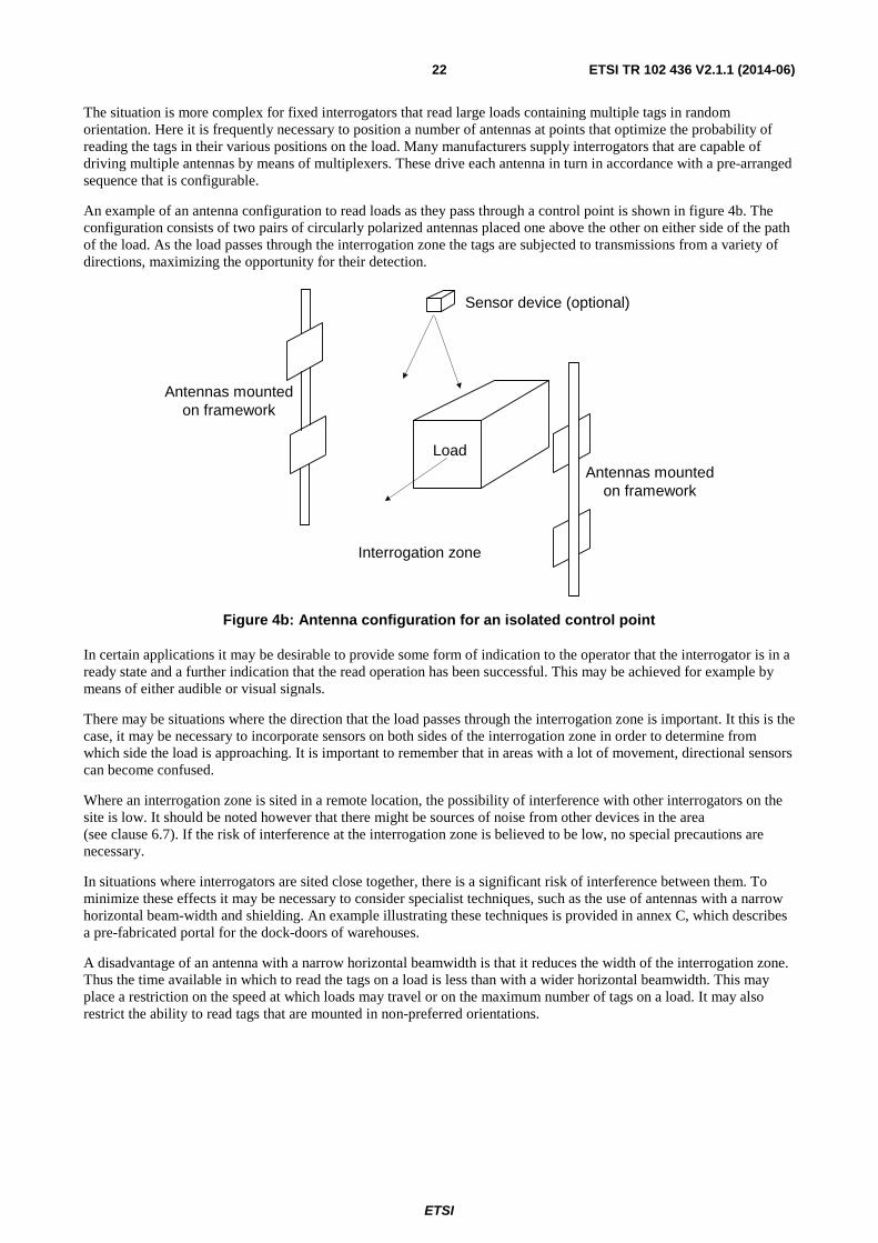
ETSI
ETSI TR 102 436 V2.1.1 (2014-06) 22
The situation is more complex for fixed interrogators that read large loads containing multiple tags in random orientation. Here it is frequently necessary to position a number of antennas at points that optimize the probability of reading the tags in their various positions on the load. Many manufacturers supply interrogators that are capable of driving multiple antennas by means of multiplexers. These drive each antenna in turn in accordance with a pre-arranged sequence that is configurable.
An example of an antenna configuration to read loads as they pass through a control point is shown in figure 4b. The configuration consists of two pairs of circularly polarized antennas placed one above the other on either side of the path of the load. As the load passes through the interrogation zone the tags are subjected to transmissions from a variety of directions, maximizing the opportunity for their detection.
Sensor device (optional)
Load
Interrogation zone
Antennas mountedon framework
Antennas mountedon framework
Figure 4b: Antenna configuration for an isolated control point
In certain applications it may be desirable to provide some form of indication to the operator that the interrogator is in a ready state and a further indication that the read operation has been successful. This may be achieved for example by means of either audible or visual signals.
There may be situations where the direction that the load passes through the interrogation zone is important. It this is the case, it may be necessary to incorporate sensors on both sides of the interrogation zone in order to determine from which side the load is approaching. It is important to remember that in areas with a lot of movement, directional sensors can become confused.
Where an interrogation zone is sited in a remote location, the possibility of interference with other interrogators on the site is low. It should be noted however that there might be sources of noise from other devices in the area (see clause 6.7). If the risk of interference at the interrogation zone is believed to be low, no special precautions are necessary.
In situations where interrogators are sited close together, there is a significant risk of interference between them. To minimize these effects it may be necessary to consider specialist techniques, such as the use of antennas with a narrow horizontal beam-width and shielding. An example illustrating these techniques is provided in annex C, which describes a pre-fabricated portal for the dock-doors of warehouses.
A disadvantage of an antenna with a narrow horizontal beamwidth is that it reduces the width of the interrogation zone. Thus the time available in which to read the tags on a load is less than with a wider horizontal beamwidth. This may place a restriction on the speed at which loads may travel or on the maximum number of tags on a load. It may also restrict the ability to read tags that are mounted in non-preferred orientations.

ETSI
ETSI TR 102 436 V2.1.1 (2014-06) 23
6.4 Configurations for near field systems at UHF The configuration of antennas for near field operation is considerably more dependent on the application than is the case for E.M. coupled systems. The reason is that the read range, field containment, and interrogator spacing are typically provided as design parameters for the antennas themselves. As an example, shelf antennas for reading garment tags have very different properties to conveyor antennas optimized for reading tags on DVDs. The present document is therefore only able to provide limited guidance on the subject.
In general, the smaller the tag antenna the shorter the reading range, with small "button" loops being limited to ranges of about 10 cm. and larger transitional tag designs limited to roughly 60 cm. Similarly, the smaller the antenna for the interrogator the shorter the range. It should be noted that the concepts of polarization and beamwidth have no meaning for near field coupling, and are only applicable to the parasitic (unwanted) EM transmissions from the near field interrogator antenna. It should also be noted that nulls in the reading field suggest using quadrature tag antennas when possible.
NOTE: Some tags contain chips that include two separate inputs. By connecting each input to its own antenna and arranging for the two antennas to be orthogonal, the reading performance of the tag is significantly improved.
As described in clause 4.2.5, near field UHF antennas for interrogators always have a far-field radiating (E.M.) component, capable of travelling over considerable distances. To minimize the risk of interference with other nearby systems, it is desirable to suppress the far-field (radiating) component of the antenna as much as possible.
For many near field applications it is only necessary to monitor tagged items at intermittent intervals. Thus a single interrogator may sequentially pole a number of different antennas. Not only does this provide a more economic installation, but it also reduces the risk of interference between adjacent interrogators.
6.5 Tags using E.M. transmissions Where possible tags should be used that offer a consistent reading range. This optimizes the probability of activating all wanted tags on loads that are in the interrogation zone and minimizes the possibility of reading unwanted tags that are positioned elsewhere.
The exact point chosen for mounting the tag on an object may have an important effect on its range. Where feasible a position (known as the "sweet spot") should be located where the reading range is least affected by the contents of the object. If it is possible to locate a sweet spot for a particular object, this position should be adopted for all other objects of the same type.
In the event that a satisfactory sweet spot cannot be found, it may be possible to insert a spacer between the tag and the object. A spacer of about 5 mm in thickness will, in many cases, recover much of the lost reading range. In the case of metal objects, special tags are available that are suitable for mounting directly on metal surfaces. However their increased cost may make their use unattractive.
Optimum reading range is achieved for E.M. transmissions when the antenna of the tag lies in the same plane as the front face of the antenna of the interrogator. If the signal from the interrogator is circularly polarized, the tag may be rotated in this plane without any reduction in reading range. However as the antenna of the tag is orientated to a position where it is at right angles to the front face of the antenna of the interrogator, its range will be progressively reduced. The effect of tag orientation on reading range is illustrated in figure 5. In this example if the antenna for the tag is mounted horizontally on an object and the orientation of the object is unknown, the reading performance will be variable. Where the application permits, this problem may be simply overcome by mounting the antenna of the tag vertically.
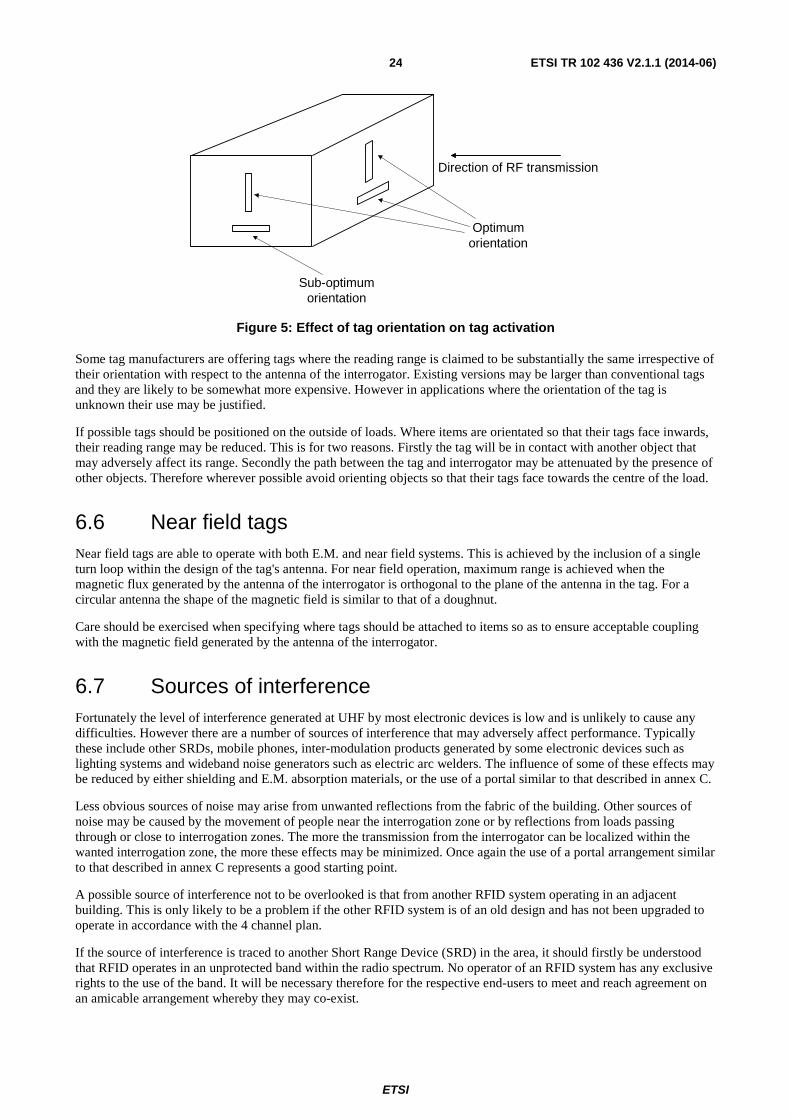
ETSI
ETSI TR 102 436 V2.1.1 (2014-06) 24
Direction of RF transmission
Optimumorientation
Sub-optimumorientation
Figure 5: Effect of tag orientation on tag activation
Some tag manufacturers are offering tags where the reading range is claimed to be substantially the same irrespective of their orientation with respect to the antenna of the interrogator. Existing versions may be larger than conventional tags and they are likely to be somewhat more expensive. However in applications where the orientation of the tag is unknown their use may be justified.
If possible tags should be positioned on the outside of loads. Where items are orientated so that their tags face inwards, their reading range may be reduced. This is for two reasons. Firstly the tag will be in contact with another object that may adversely affect its range. Secondly the path between the tag and interrogator may be attenuated by the presence of other objects. Therefore wherever possible avoid orienting objects so that their tags face towards the centre of the load.
6.6 Near field tags Near field tags are able to operate with both E.M. and near field systems. This is achieved by the inclusion of a single turn loop within the design of the tag's antenna. For near field operation, maximum range is achieved when the magnetic flux generated by the antenna of the interrogator is orthogonal to the plane of the antenna in the tag. For a circular antenna the shape of the magnetic field is similar to that of a doughnut.
Care should be exercised when specifying where tags should be attached to items so as to ensure acceptable coupling with the magnetic field generated by the antenna of the interrogator.
6.7 Sources of interference Fortunately the level of interference generated at UHF by most electronic devices is low and is unlikely to cause any difficulties. However there are a number of sources of interference that may adversely affect performance. Typically these include other SRDs, mobile phones, inter-modulation products generated by some electronic devices such as lighting systems and wideband noise generators such as electric arc welders. The influence of some of these effects may be reduced by either shielding and E.M. absorption materials, or the use of a portal similar to that described in annex C.
Less obvious sources of noise may arise from unwanted reflections from the fabric of the building. Other sources of noise may be caused by the movement of people near the interrogation zone or by reflections from loads passing through or close to interrogation zones. The more the transmission from the interrogator can be localized within the wanted interrogation zone, the more these effects may be minimized. Once again the use of a portal arrangement similar to that described in annex C represents a good starting point.
A possible source of interference not to be overlooked is that from another RFID system operating in an adjacent building. This is only likely to be a problem if the other RFID system is of an old design and has not been upgraded to operate in accordance with the 4 channel plan.
If the source of interference is traced to another Short Range Device (SRD) in the area, it should firstly be understood that RFID operates in an unprotected band within the radio spectrum. No operator of an RFID system has any exclusive rights to the use of the band. It will be necessary therefore for the respective end-users to meet and reach agreement on an amicable arrangement whereby they may co-exist.

ETSI
ETSI TR 102 436 V2.1.1 (2014-06) 25
7 Recommendations for installation This clause covers the standard practices and procedures that should be observed by system integrators during the installation and commissioning of systems on site.
7.1 Antenna fixtures During their normal working life antenna fixtures will be subject to occasional blows from heavy objects moving at speed. It is therefore essential that any exposed antennas are given adequate physical protection. Similarly it will be necessary to ensure that any frames used for mounting antennas are suitably robust. If the frames are manufactured from metal care should be taken to ensure that the choice of metal does not give rise to corrosion. Steel frames should be galvanised or covered with a suitable protective coating. Where dissimilar metals are in contact with each other wherever possible they should be selected from the yellow metal series such as copper, brass, silver, nickel, or gold. All parts of the frame should be in good electrical contact with each other and the structure should be earthed at a single point.
Aluminium structures should not be anodised as this is likely to insulate the different components and lead to problems with their conductivity and earthing.
7.2 Selection of antennas Having determined the necessary beamwidth of the antenna, it will be important to check with the manufacturer of the interrogator that the combination of the antenna and interrogator is compliant with the R&TTE Directive. If the manufacturer of the interrogator has no knowledge of the selected antenna, the system integrator should ask the manufacturer of the antenna to confirm that the combination is compliant. Alternatively the system integrator may take the steps necessary to ensure compliance.
When mixing equipment such as interrogators, cables and antennas from different manufacturers, ultimately it is the responsibility of the systems integrator to ensure and document that the combination of equipment satisfies the requirements of the Directive and that the radiated power does not exceed the permitted limits.
The maximum permissible power supplied by the interrogator to the antenna will be dependent on the gain of the selected antenna and its associated cabling. The interrogator should be adjusted to ensure that the power radiated by the selected antenna falls within the limits permitted by the country in which the equipment will be operated.
The manufacturer of the interrogator should be asked to provide the documentation on how to make the necessary adjustments to the transmitter drive signal.
7.3 Positioning of the antenna Wherever possible fixed antennas should be mounted such that the radiation path is clear of any significant metalwork. Failure to do this will lead to a reduction in the gain of the antenna and a consequent reduction in the range at which tags may be read. Where applicable care should also be taken to ensure that any nearby metalwork does not cause unwanted reflections, e.g. by the use of e.m. absorbent material. In certain applications it may be necessary to protect the front of the antenna with a suitable RF transparent material.
7.4 Outside antennas Antennas that may be exposed to outside conditions, such as at dock doors, should be sufficiently robust to survive the environment over a number of years. Where necessary they should be protected against strong winds and should be resistant to rain and high humidity. The outer casings of the antennas should be made of a material that will withstand prolonged exposure to ultra-violet light. They should also be capable of operating satisfactorily over the anticipated temperature range. In addition it may be prudent to include some form of protection against lightning. Unless guidance on lightning protection is provided in the manual for the interrogator, the manufacturer of the antenna should be asked for advice.
Weather conditions may cause a reduction in system performance. This may be particularly evident where antennas are sited at an entrance to a building. A reduction in reading range will often be observed in damp or foggy conditions.

ETSI
ETSI TR 102 436 V2.1.1 (2014-06) 26
All external connectors to the antenna should be suitable for outside use, e.g. either protected against humidity or water proof. For example they may be protected by means of PolyIsoButylene (PIB) self-amalgamating tape. Particular attention should also be paid to the shedding of surface water.
7.5 Antennas for GSM-R receivers GSM-R receiver modules may either be built into each interrogator or alternatively a single receiver may serve all of the interrogators on the site.
In the case where each interrogator has its own GSM-R receiver module, its antenna will be located close to the interrogator. The antenna will typically be a patch antenna. Care should be taken to ensure that the antenna is not positioned where it will receive excessive signal levels from the interrogator. Failure to do this may lead to damage to the module. The GSM-R antenna should be positioned so that it is best able to receive BCCH signals from any GSM-R base stations that may be in the neighbouring area.
Where a single GSM-R module is used it may be mounted on the roof of the building. The antenna should be positioned in a location, which gives maximum coverage. It should be fixed to a point on the roof which is sufficiently secure to withstand high winds. The feeder cable from the antenna to the GSM-R module should be kept as short as reasonably possible. Both the receiver module and its antenna should be adequately protected from adverse weather conditions.
On sites where it is not possible to mount the antenna on the roof, it may alternatively be mounted on a radio mast. The radio mast should be sufficiently spaced from any building and in a position and height that gives maximum coverage in all directions. All external electrical connections should be designed to withstand adverse weather conditions.
Preferably the output from the GSM-R module will be distributed to all of the fixed interrogators on the site either by radio or by means of a multi-drop cable.
Once installed each GSM-R receiver should be calibrated to detect a BCCH signal at a threshold level down to -98 dBm e.r.p. assuming a 0 dBd antenna gain. This process should take into account the loss of the feeder cable.
Mobile devices such as hand held readers or interrogators mounted on vehicles (e.g. fork lift trucks) should be fitted with their own integral GSM-R receiver modules and antennas or alternatively be connected to a central GSM-R receiver by means of a radio link.
7.6 Cabling Use the feeder cables and connectors recommended by the manufacturer of the interrogator. Wherever possible feeders should be run over the most direct route since this will give minimum radiation from the cable and the least insertion loss. Cables should be run in accordance with the recommended bending radii. Consideration should also be given to the insertion loss of RF cables of different lengths. If it is necessary for feeders to cross mains or data cables, they should do so at right angles.
Mains and data cables should be protected by means of surge arrestors.
Mains cabling should be run in accordance with local and national regulations. The minimum requirement as far as the user is concerned is the inclusion of Residual Current Devices (RCD).
All cables from interrogators to the computer room should be protected so that they cannot easily be damaged. Where possible interrogator cables and mains cables to the computer room should be run through separate ducts.
All cables should be identified at each end and their details recorded in the installation records for the site.
7.7 Earthing (Fixed Interrogators) A satisfactory earthing system (e.g. standard earth provided in the building) is an important and often neglected aspect of any installation. It is recommended that the measured earth value should be less than 10 Ohms. However the most important feature is that the system should be equipotential across the site.
It is important to ensure that all interrogators are adequately earthed. In addition all portals or antenna mounting structures that are constructed from metal should be bonded to earth at a single point on the structure.

ETSI
ETSI TR 102 436 V2.1.1 (2014-06) 27
Connections to the site earth (where corrosion may be unavoidable) should be made using sacrificial anodes of a material compatible with the structure being earthed.
A method of measurement to determine the value of the earth at a site is described in annex B.
Before making any changes to an earthing system, it is important to consult the owners of the site and the relevant electricity supply authority.
7.8 RFID and Short Range Devices operating within the same area
To ensure equitable sharing between all users of the lower and upper bands, EN 302 208 [i.1] (RFID) and EN 300 220 [i.2] (SRDs) impose a number of rules.
Information is provided in clause 4.2.4 above.
8 Commissioning
8.1 Setting to work It is essential that the system is set to work in a thorough and logical manner. Before starting a plan should be prepared listing the steps in preferred sequence necessary to commission each interrogator and its associated equipment. Suitable paperwork should be prepared to record the key set-up conditions for all equipment forming part of the installation.
A suggested procedure for commissioning is provided in annex C.
In many installations not all parts of the system will be supplied by the same sub-contractor. In this situation the components provided by each supplier will most probably be subject to separate commissioning and acceptance.
Once the different parts of the system have been accepted, the full system will usually be tested and accepted against pre-agreed performance criteria.
Any maintenance agreement and warranty will often commence once the end user has formally accepted the system, or sub-system, provided by a supplier. This is frequently set out in the terms of the supply contract.
8.2 Site records Comprehensive and accurate records are essential for efficient fault finding and for the proper maintenance of the installation. The records should include cable schedules giving details of all cables that form part of the installation. The records should also include any final measurements made at each interrogator during commissioning. In addition the records should contain manufacturers' documentation for each item of equipment that makes up the total system.
A minimum of two copies of the records should be produced. One copy should be passed to the customer while the second copy should be retained by the installer.
9 Maintenance To ensure continued satisfactory performance of the system it is vital that arrangements are made with the customer for regular maintenance. In general maintenance will fall into two categories. There will be periodic site maintenance that will be performed by the end-user on a regular basis. In addition the organization responsible for overall maintenance of the installation may undertake planned maintenance visits to site to check that the essential parameters of the system are correct. Amongst other things this may include inspection of both cabling and earthing and a check of all key system parameters. All periodic tasks to be undertaken by the end-user and by the organization responsible for overall maintenance of the installation should be detailed thoroughly in a maintenance document and agreed by the parties.

ETSI
ETSI TR 102 436 V2.1.1 (2014-06) 28
The maintenance agreement may contain a list of recommended spare parts to be held by the end-user.
The agreement on maintenance may also include arrangements for call-out in the event of a system failure.

ETSI
ETSI TR 102 436 V2.1.1 (2014-06) 29
Annex A: Conversion of units of measurement
A.1 Measurements of power Measurements of power that are made in electronics frequently span many orders of magnitude. The handling of these figures is made simpler if logarithmic units are used . For convenience measurements are made in terms of relative power in units of decibels (dB). For two power levels P1 and P2 the relative power expressed in dB is:
dB = 10 x Log10 (P1/P2)
It is common practice to measure changes of power in terms of voltage across a fixed load. Since power is proportional to the square of the voltage, the relationship in dB in terms of voltages V1 and V2 becomes:
dB = 10 x Log10 (V12/V2
2), or
dB = 20 x Log10 (V1/V2)
It is often useful to refer to power levels relative to a known value. For radio signals the level of 1 milliwatt is frequently used as a reference point and this is written as dBm. In this case the relationship becomes:
dBm = 10 x Log10 (P1/1)
where P1 is in milliwatts.
Similarly power levels may be based on a range of other common parameters. The most frequently used are listed below:
dBc a measurement of power relative to the power of the carrier signal;
dBi a measurement of power from an antenna relative to the same power radiated by an isotropic antenna (an isotropic antenna is a theoretical antenna that radiates power equally in all directions).
In Europe measurements of radiated power below 1 GHz are made using a half wave dipole and recorded as e.r.p. (effective radiated power) in dBd. The relationship between the radiated power from an isotropic antenna (eirp) and e.r.p. is the gain of a half wave dipole, which is 2,15 dB.

ETSI
ETSI TR 102 436 V2.1.1 (2014-06) 30
Annex B: Earthing systems
B.1 Earth System Minimum Requirements The following criteria need to be met or exceeded:
a) A low resistance path to earth with a low inductance such that the overall impedance does not exceed 10 ohms.
b) Life expectancy of the earth system to be at least equal to that of the structure it is protecting.
c) Arrangements for regular testing by the provision of removable test links at strategic points.
An earth termination should comprise:
a) a ring connected to vertical electrodes (rods) not less than 9 m total length; or
b) an earth "mat" of radial conductors of not less than 20 m total length and buried at least 500 mm below ground level.
Where electrodes cannot be buried to the minimum 500 mm depth, it should be noted that there is an increased risk of a step potential, e.g. electrodes terminated at surface level produce an 80 % greater potential gradient along the surface.
B.2 Typical electrode and array characteristics
B.2.1 Vertical rod It is recommended that lower earth resistivity will be obtained by driving several thin copper rods interconnected, rather than a single rod of the same overall mass.
These should be at least 1 m apart and driven to a depth of at least 2 m.
The basic calculation for assessing earth resistance for a vertical high conductivity rod.
Where P = soil resistivity in Ohm-metres. All dimensions in metres.
Figure B.1

ETSI
ETSI TR 102 436 V2.1.1 (2014-06) 31
B.2.2 Buried ring When used as a primary electrode. Not to be confused with vertical electrode interconnecting conductors.
Where P =soil resistivity in Ohm-metres. All dimensions in metres.
Figure B.2
B.2.3 Buried grid
Where P = soil resistivity in Ohm-metres. All dimensions in metres.
Figure B.3
B.2.4 Measurement of soil resistivity Soil Resistivity
The most important remaining factor influencing the impedance of the earthing system is the impedance of the medium in which the earth electrodes are situated, i.e. the soil.
Because soil resistivity is such an important factor governing the performance of earth electrodes, it needs to be discussed in some detail. Soil resistivity is expressed in Ohm-metres. This unit is the resistance between the two opposite faces of a one metre cube of uniform soil. The value obtained is thus in Ohm-metre2 per metre, which is traditionally shortened to Ohm-metres. Some typical resistivity values are given in table B.1.
Table B.1: Typical values of resistivity for different soils
Type Resistivity (Ohm-metre) Garden soil/alluvial clay 5 to 50 London clay 5 to 100 Clay, sand and gravel 40 to 250 Porous chalk 30 to 100 Quartzite/crystalline limestone 300+ Rock 1 000 to 10 000 Gneiss/igneous rock 2 000+ Dry concrete 2 000 to 10 000 Wet concrete 30 to 100 Ice 10 000 to 100 000

ETSI
ETSI TR 102 436 V2.1.1 (2014-06) 32
Temperature and water content have an important influence on the soil resistivity and hence the performance of the earthing system. An increase in water content causes a steep reduction in resistivity until the 20 % level is reached when the effect begins to level out. Dissolved minerals and salts in the water may help further to reduce the resistivity, particularly where these are naturally occurring and do not become diluted over time. The water content will vary seasonally and is likely to cause variations in the impedance of the earthing system. The very high resistivity of ice (see table 1.) compared to water, shows why it is necessary to install the electrodes beneath the freezing line. This is typically between 0,4 m and 0,6 m, but may be deeper in exposed, mountainous locations.
Measurement of Soil Resistivity:
It is important that the resistivity is assessed as accurately as possible, since the value of the resistance of the electrode is directly proportional to the soil resistivity. If the incorrect value of soil resistivity is used at the design stage, the measured impedance of the earthing system may prove to be significantly different to that planned. This could, in turn, have serious financial consequences.
The test is traditionally carried out using a four-terminal earth test (Wenner Method). Four spikes are driven into the ground as shown in the diagram, spaced a distance of "a" metres apart. The depth to which each spike is driven should not exceed "a" divided by 20 and is not normally greater than 0,3 m.
Figure B.4
It is important to ensure that the test spikes are not inserted in line with buried metal pipes or cables, as these will introduce measurement errors.
A known current from a constant current generator is passed between the outer electrodes. The potential drop (a function of resistance) is then measured between the two inner electrodes.
All of the parameters may be related in the expression below to give the soil resistivity value ρ:
4π AR
ρ = ___________________________________Ω - metres
1 + 2A - 2A
____________ __________
√ (4A2 + 4B2 ) √ (4A2 - 4B2 )
Where:
A = distance between electrodes in meters.
B = Electrode depth in meters.
R = Resistance in ohms.
If A > 20B, the expression becomes:
ρ = 2πAR Ohm-metres

ETSI
ETSI TR 102 436 V2.1.1 (2014-06) 33
B.3 Earthing of support structures and buildings
B.3.1 Ancillary equipment external to buildings Fuel tanks, air conditioning enclosures, etc. should be bonded separately to the building earth system.
B.3.2 Metal support poles on buildings In addition any poles, brackets, bracing stays, etc. should be bonded to the building earth system.
B.3.3 Metal security fences Where a close metal fence is within 2,5 m of the site it should be directly bonded between a contact point and the earth ring.
Where long perimeter fences are in place it is clearly impractical to use this method. Moreover there is an increased risk under certain strike conditions where the fence will conduct high potentials to points distant from the bonding point. It is therefore recommended that where long fences are present, these should be directly earthed at intervals along the perimeter.
B.4 Interconnection of lightning protection systems with power supply earthing arrangements
Consideration of overall site safety indicates that equipotential bonding of all metal objects on and within site structures should be an ideal to be pursued if possible.
However, examination of the various scenarios that exist for all types of site, shows that A.C. power supply arrangements vary widely between sites and are further complicated by national standards appropriate to the country of origin. This is particularly true of practices adopted for earth paths provided by electricity supply organizations, where application will depend on the prevailing terrain and the supply chain configuration.
In some circumstances it is possible that the integrity of the A.C. supply earth, may be compromised by incorrect interconnection of lightning protection and supply related earthing arrangements.
It is therefore strongly recommended, when planning overall site protection, that the relevant power supply authority is consulted in the process at an early stage.

ETSI
ETSI TR 102 436 V2.1.1 (2014-06) 34
Annex C: Prefabricated portals The portal illustrated in this annex is intended for use at dock doors in warehouses. However it may be possible to adapt the principles for use in other applications.
Typically the portal would be approximately 3 m wide, 3 m high and 1,6 m in depth. Portals may be constructed as pre-fabricated units, which reduce the installation effort required on site.
Sensor device (optional)
Interrogation zone
Antennas spaced 15cm off metal mesh
Load Antennas spaced 15cm off metal mesh
1.6 m
3 m
3 m
Figure C.1: Illustration of portal configuration
The arrangement for the antennas is very similar to figure 4b in clause 6.3. For many applications the horizontal beamwidth of each antenna is limited to not more than 30 degrees although typically the vertical beamwidth may be as much as 70 degrees. The combined effect of the narrower beam-width and the metal mesh is to reduce the strength of the field from the main lobe of each antenna into the adjacent lane. An attenuation of at least 10 dB should be achievable. Thus at the centre of a portal the difference in field levels between its interrogator and that from the interrogator in the adjacent portal typically will be at least 20 dB. This represents a good design objective to ensure satisfactory performance.
In addition the signal strength received from any activated tags in adjacent lanes is much less. Thus the possibility of interference between adjacent lanes is greatly reduced. Portals also greatly reduce the possibility of unintentionally activating unwanted tags on loads that are being moved some distance from the interrogation zone.

ETSI
ETSI TR 102 436 V2.1.1 (2014-06) 35
Annex D: Commissioning procedure Since each site is different it is impossible to describe every eventuality. This annex should therefore only be used as a general guide. The setting to work procedures covers only interrogators and their associated equipment. They do not include the equipment in the computer room or the process for the setting to work of the full system.
The commissioning of the interrogators may be undertaken prior to installation, either on site, or at the premises of the solution provider, as laid down in the agreement.
Once the equipment has been installed in many cases final adjustments will be necessary to meet the specific requirements of the site. These may arise as a consequence of environmental considerations, performance objectives, antenna alignment and regulatory compliance. These adjustments may require the use of a laptop for connection to individual interrogators.
Although this list is not exhaustive, commissioning may cover the following activities:
• Adjustment of settings to the transmit power of the interrogator. Note that this may vary across antenna ports to accommodate differences in antenna cable lengths.
• Adjustment of settings for the required tag protocol(s) and data lengths.
• Correct setting of the network infrastructure identification parameters i.e. IP Address, Device Name, SNMP Community String etc.
• If necessary the upload of firmware to the level agreed with the customer.
• Configuration of any pre-agreed radio frequency sub-band mapping.
• Configuration, if required, of general interrogator parameters to handle the operation of external devices such as external triggers and audio/visual outputs.
• Configuration, if required, of any customized functions within the system i.e. a write-only station or a re-work station.
• Completion of a full set of documentation covering all equipment that falls within the responsibility of the installer.
Note that the process of commissioning the system is a separate activity to an acceptance test, which will take place afterwards.

ETSI
ETSI TR 102 436 V2.1.1 (2014-06) 36
Annex E: Bibliography
• ETSI EG 200 053 (V1.5.1): "Electromagnetic compatibility and Radio spectrum Matters (ERM); Radio site engineering for radio equipment and systems".
• ETSI EN 301 489-1: "Electromagnetic compatibility and Radio spectrum Matters (ERM); Electromagnetic compatibility (EMC) standard for radio equipment and services: Common technical requirements".
• ETSI EN 301 489-3: "Electromagnetic compatibility and Radio spectrum Matters (ERM); Electromagnetic compatibility and Radio spectrum Matters (ERM); Specific conditions for short range devices operating on frequencies between 9 kHz and 40 GHz".
• CENELEC EN 50357: "Evaluation of human exposure to electromagnetic fields from devices in the operating range 0 Hz to 10 GHz, used in the Electronic Article Surveillance (EAS), Radio Frequency Identification (RFID) and similar applications".
• CENELEC EN 50364: "Limitation of human exposure to electromagnetic fields from devices in the operating range 0 Hz to 10 GHz, used in the Electronic Article Surveillance (EAS), Radio Frequency Identification (RFID) and similar applications".
• CENELEC EN 60950-1: "Information Technology - Cabling Installation (in several parts)".
• CEPT ECC Report 037: "Compatibility of planned SRD applications in 863 - 870 MHz".

ETSI
ETSI TR 102 436 V2.1.1 (2014-06) 37
History
Document history
V1.1.1 December 2005 Publication
V1.2.1 February 2008 Publication
V2.1.1 June 2014 Publication