TR 034 SIMULATION PARAMETERS FOR THEORETICAL LTE ...
19
TR 034 SIMULATION PARAMETERS FOR THEORETICAL LTE eMBMS NETWORK STUDIES TECHNICAL REPORT Geneva December 2015
-
Upload
truongthuy -
Category
Documents
-
view
229 -
download
1
Transcript of TR 034 SIMULATION PARAMETERS FOR THEORETICAL LTE ...

TR 034
SIMULATION PARAMETERS FOR THEORETICAL LTE eMBMS NETWORK STUDIES
TECHNICAL REPORT
Geneva December 2015

* Page intentionally left blank. This document is paginated for two sided printing
TR 034 Simulation parameters for theoretical LTE eMBMS network studies
3
Contents
Introduction .............................................................................................. 5 Table 1: System related parameters ........................................................................... 7
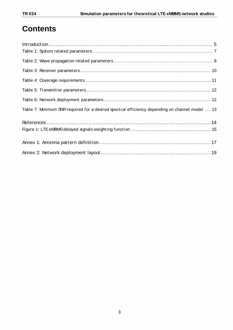
Table 2: Wave propagation related parameters .............................................................. 8
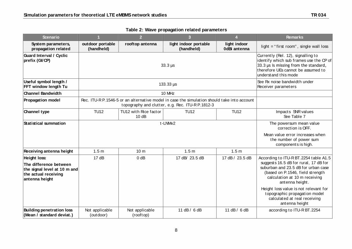
Table 3: Receiver parameters .................................................................................. 10
Table 4: Coverage requirements ............................................................................... 11
Table 5: Transmitter parameters .............................................................................. 12
Table 6: Network deployment parameters ................................................................... 12
Table 7: Minimum SNR required for a desired spectral efficiency depending on channel model .... 13
References .............................................................................................. 14 Figure 1: LTE eMBMS delayed signals weighting function .................................................. 15
Annex 1: Antenna pattern definition ................................................................ 17
Annex 2: Network deployment layout ............................................................... 19

Simulation parameters for theoretical LTE eMBMS network studies TR 034
4
* Page intentionally left blank. This document is paginated for two sided printing

TR 034 Simulation parameters for theoretical LTE eMBMS network studies
5
Simulation parameters for theoretical LTE eMBMS network studies
EBU Committee First Issued Revised Re-issued
TC 2015
Keywords: LTE, eMBMS, 3GPP, network simulation, network performance.
Introduction This document lists relevant technical parameters to be used for theoretical LTE eMBMS1
This work was motivated by the experienced difficulties in interpreting and comparing the results of different studies on network performance and coverage. This was largely due to the following factors:
radio access network studies in order to yield comparable results in different investigations from various sources. It is a result of cooperation between representatives from the broadcast and the mobile industry.
· Different input assumptions and parameters used in different studies
· Parameters may not have been treated in a consistent way across different studies
· Different interpretations of what constitutes network coverage which led to different coverage criteria applied in different studies.
Therefore, the intention of this document is to establish a representative list of simulation parameters in order to facilitate comparison between different studies and the possibility to replicate their results.
This list is limited to those parameters that are necessary or LTE eMBMS coverage simulation. Neither unicast nor uplink parameters have been included.
Values for the parameters given in Tables 1 - 7 below are considered to be realistic. Nevertheless, this set of values may need to be expanded and refined for the purpose of planning real eMBMS networks.
It is recommended to keep the system related parameters (Table 1) and those related to wave propagation (Table 2) and receiver characteristics (Table 3) unchanged in the simulations.
Parameters related to coverage requirements (Table 4) , transmitter parameters (Table 5) and network deployment (Table 6) can be changed in order to investigate performance of different network configurations in different scenarios.
Table 7 provides the values for a minimum SNR required for a desired spectral efficiency depending on channel model.
Antenna pattern definition is given in Annex 1 and the assumed theoretical network layout in Annex 2.
1 The parameters of LTE eMBMS are based on the 3GPP Release 12 and may need to be reviewed following future 3GPP Releases.

Simulation parameters for theoretical LTE eMBMS network studies TR 034
6
* Page intentionally left blank. This document is paginated for two sided printing

TR 034 Simulation parameters for theoretical LTE eMBMS network studies
7
Table 1: System related parameters
Scenario 1 2 3 4 Remarks Reception mode System parameters
outdoor portable (handheld)
Fixed (rooftop antenna)
light indoor portable (handheld with integrated
antenna)
light indoor 0 dBi antenna light = “first room”, single wall loss
Frequency The parameters given in the table are applicable for the frequency band 470 - 790 MHz. Where a parameter is frequency-dependent, values are given for 470 MHz and 790 MHz.
Required SINR See Table 7
SINR is used in mobile radio access network planning. In the broadcasting methodology it is called C/(N+I)
Signal time probability: wanted / interfering:
50% / 1.75% (wanted / interfering) Quality requirements:
availability of the wanted signal is guaranteed for high percentage of time
protection against interference is guaranteed for high percentage of time àinterfering field strength must not exceed an interference level for more than small percentage of time
a “corrected time” of 1.75% should be used for individual interference paths to give an estimate of aggregate power at 1% time according to [6]
Pixel size 100 x 100m² 100 x 100m² 100 x 100m² 100 x 100m²
Simulation parameters for theoretical LTE eMBMS network studies TR 034
8
Table 2: Wave propagation related parameters
Scenario 1 2 3 4 Remarks
System parameters, propagation related
outdoor portable (handheld)
rooftop antenna light indoor portable (handheld)
light indoor 0dBi antenna light = “first room”, single wall loss
Guard Interval / Cyclic prefix (GI/CP)
33.3 µs
Currently (Rel. 12), signalling to identify which sub frames use the CP of 33.3 μs is missing from the standard, therefore UEs cannot be assumed to understand this mode
Useful symbol length / FFT window length Tu 133.33 µs See Rx noise bandwidth under
Receiver parameters
Channel Bandwidth 10 MHz
Propagation model Rec. ITU-R P.1546-5 or an alternative model in case the simulation should take into account topography and clutter, e.g. Rec. ITU-R P.1812-3
Channel type TU12 TU12 with Rice factor 10 dB
TU12 TU12 Impacts SNR values See Table 7
Statistical summation t-LNMv2 The powersum mean value correction is OFF.
Mean value error increases when the number of power sum
components is high.
Receiving antenna height 1.5 m 10 m 1.5 m 1.5 m
Height loss:
The difference between the signal level at 10 m and the actual receiving antenna height
17 dB 0 dB 17 dB/ 23.5 dB 17 dB / 23.5 dB According to ITU-R BT.2254 table A1.5 suggests 16.5 dB for rural, 17 dB for suburban and 23.5 dB for urban case
(based on P.1546, field strength calculation at 10 m receiving
antenna height.
Height loss value is not relevant for topographic propagation model
calculated at real receiving antenna height
Building penetration loss (Mean / standard deviat.)
Not applicable (outdoor)
Not applicable (rooftop)
11 dB / 6 dB 11 dB / 6 dB according to ITU-R BT.2254

TR 034 Simulation parameters for theoretical LTE eMBMS network studies
9
Table 2: continued
Scenario 1 2 3 4 Remarks
System parameters, propagation related
outdoor portable (handheld)
rooftop antenna light indoor portable (handheld)
light indoor 0dBi antenna light = “first room”, single wall loss
Location variation / shadowing standard deviation
5.5 dB 5.5 dB 5.5 dB 5.5 dB according to ITU-R BT.2254
Shadowing correlation uncorrelated uncorrelated uncorrelated uncorrelated optional: with inter-site shadowing correlation
Man-made noise 0 dB 0 dB 0 dB 1 dB according to ITU-R BT.2254
Geographical coordinate system (for distance calculations)
UTM UTM UTM UTM
Simulation parameters for theoretical LTE eMBMS network studies TR 034
10
Table 3: Receiver parameters
Scenario 1 2 3 4 Remarks
Receiver parameters outdoor portable (handheld)
rooftop antenna light indoor portable (handheld)
light indoor 0dBi antenna light = “first room”, single wall loss
Receiver noise figure 9 dB 6 dB 9 dB 6 dB 6 dB according to ITU-R BT.2254
9 dB according to 3GPP TR25.814
Receiver noise bandwidth 9 MHz 9 MHz 9 MHz 9 MHz
Rx antenna (gain & pattern)
-7.35 dBi non-directional
13.15 dBi discrimination pattern
according to ITU-R BT.419-3
band IV, V
-7.35 dBi non-directional
0 dBi non-directional
according to ITU-R BT.2254
Antenna cable loss 0 dB 4 dB 0 dB 0 dB according to ITU-R BT.2254
Rx diversity Yes No Yes Yes Rx diversity gain is included in the spectral efficiency table.
Implementation margin 1 dB 1 dB 1 dB 1 dB The required SNR as given in Table 7 has to be increased by the implementation margin.
Body loss at receiver 2 dB The device is in video viewing position (not in talking position or
in a pocket).
0 dB 2 dB The device is in video
viewing position (not in talking position or in a
pocket).
0 dB
Equalization Interval 60 µs
weighting function according to ITU-R BT.2254 (DVB-T2), applied to LTE
90% of Nyquist time LTE: separation of pilot-bearing
carriers = 2
à theoretical limit is Tu/2
See Figure 1 for correct weight function.
Rx synchronization method maximum C/I maximum C/I maximum C/I maximum C/I

TR 034 Simulation parameters for theoretical LTE eMBMS network studies
11
Table 4: Coverage requirements
Scenario 1 2 3 4 Remarks
Coverage requirements outdoor portable (handheld)
rooftop antenna light indoor portable (handheld)
light indoor 0dBi antenna light = “first room”, single wall loss
Target coverage probability within a pixel
x% of locations/area within a pixel where the required threshold is exceeded x= 70% (Acceptable coverage )
or 95 % (Good coverage)
Target area coverage percentage of pixels where the threshold x% is met
y% of pixels within a given service area which meet the requirement Output value.
A pixel is either covered or not covered.
Target area coverage is subject to regulatory requirements and business considerations.
Target population coverage z% population coverage Output value
Plays a role in interpretation of the y% service area coverage.
Target population coverage is subject to regulatory requirements and business considerations.
User distribution given by population density map;
Homogeneous within the pixel
given by population density map;
Homogeneous within the pixel
given by population density map;
Homogeneous within the pixel
given by population density map;
Homogeneous within the pixel
Scope: area coverage analysis; user distribution is relevant only for population coverage analysis
Simulation parameters for theoretical LTE eMBMS network studies TR 034
12
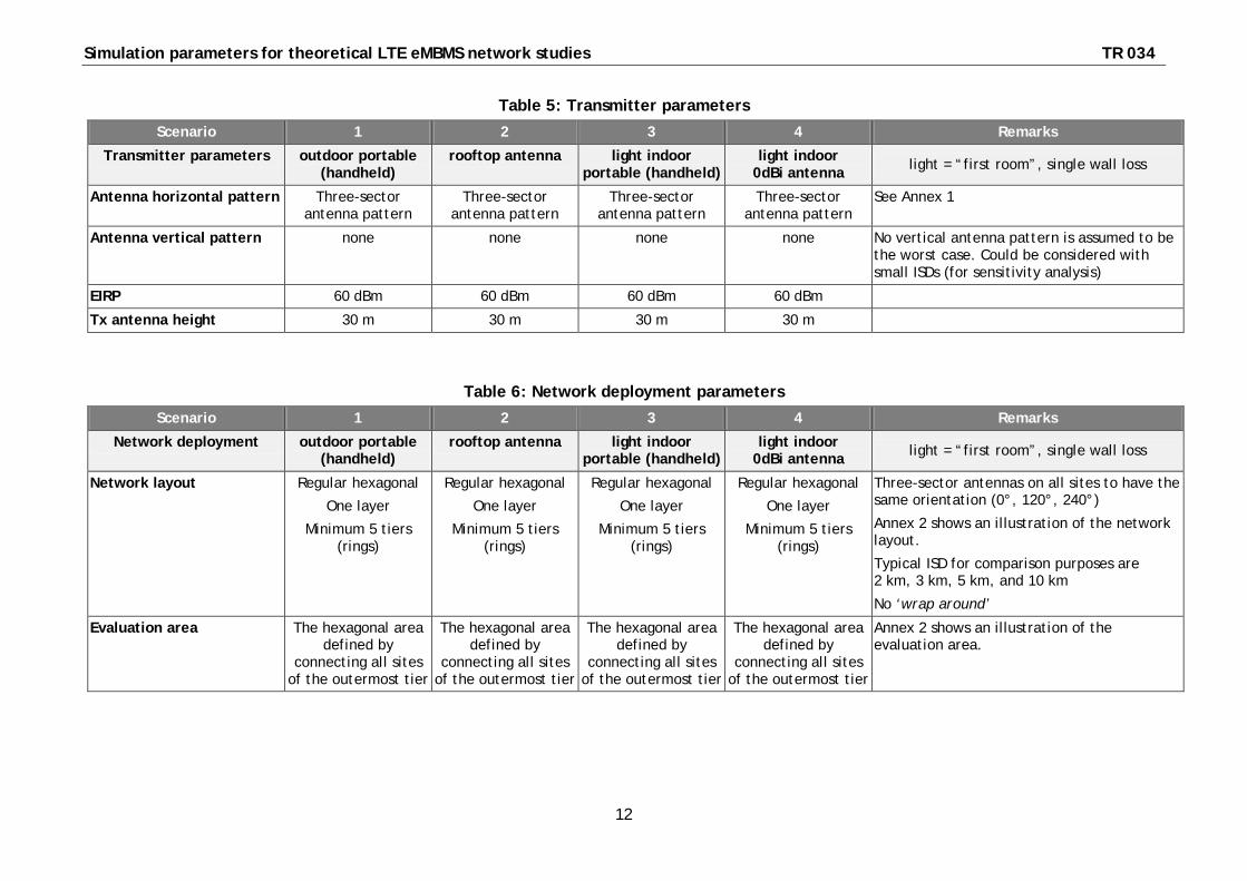
Table 5: Transmitter parameters
Scenario 1 2 3 4 Remarks
Transmitter parameters outdoor portable (handheld)
rooftop antenna light indoor portable (handheld)
light indoor 0dBi antenna light = “first room”, single wall loss
Antenna horizontal pattern Three-sector antenna pattern
Three-sector antenna pattern
Three-sector antenna pattern
Three-sector antenna pattern
See Annex 1
Antenna vertical pattern none none none none No vertical antenna pattern is assumed to be the worst case. Could be considered with small ISDs (for sensitivity analysis)
EIRP 60 dBm 60 dBm 60 dBm 60 dBm
Tx antenna height 30 m 30 m 30 m 30 m
Table 6: Network deployment parameters
Scenario 1 2 3 4 Remarks
Network deployment outdoor portable (handheld)
rooftop antenna light indoor portable (handheld)
light indoor 0dBi antenna light = “first room”, single wall loss
Network layout Regular hexagonal
One layer
Minimum 5 tiers (rings)
Regular hexagonal
One layer
Minimum 5 tiers (rings)
Regular hexagonal
One layer
Minimum 5 tiers (rings)
Regular hexagonal
One layer
Minimum 5 tiers (rings)
Three-sector antennas on all sites to have the same orientation (0°, 120°, 240°)
Annex 2 shows an illustration of the network layout.
Typical ISD for comparison purposes are 2 km, 3 km, 5 km, and 10 km
No ‘wrap around’
Evaluation area The hexagonal area defined by
connecting all sites of the outermost tier
The hexagonal area defined by
connecting all sites of the outermost tier
The hexagonal area defined by
connecting all sites of the outermost tier
The hexagonal area defined by
connecting all sites of the outermost tier
Annex 2 shows an illustration of the evaluation area.
TR 034 Simulation parameters for theoretical LTE eMBMS network studies
13
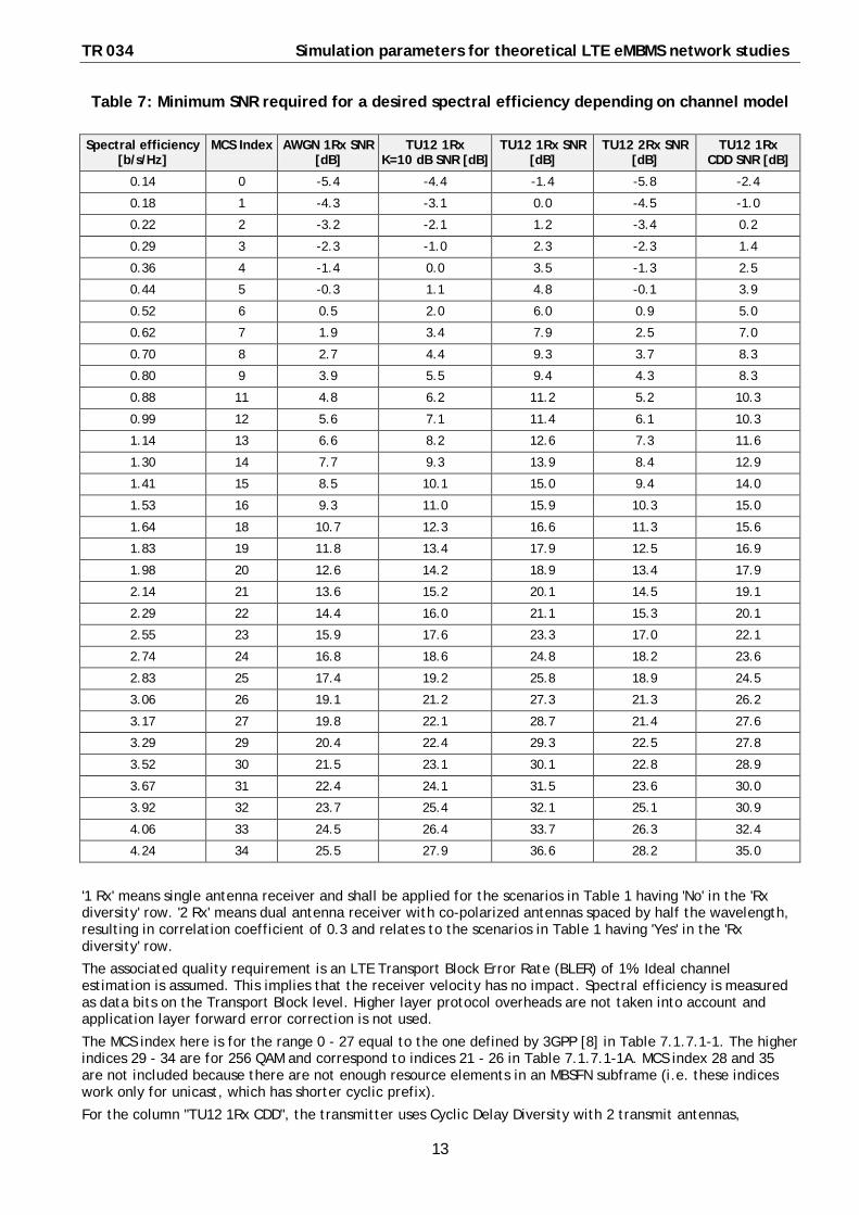
Table 7: Minimum SNR required for a desired spectral efficiency depending on channel model
Spectral efficiency [b/s/Hz]
MCS Index AWGN 1Rx SNR [dB]
TU12 1Rx K=10 dB SNR [dB]
TU12 1Rx SNR [dB]
TU12 2Rx SNR [dB]
TU12 1Rx CDD SNR [dB]
0.14 0 -5.4 -4.4 -1.4 -5.8 -2.4
0.18 1 -4.3 -3.1 0.0 -4.5 -1.0
0.22 2 -3.2 -2.1 1.2 -3.4 0.2
0.29 3 -2.3 -1.0 2.3 -2.3 1.4
0.36 4 -1.4 0.0 3.5 -1.3 2.5
0.44 5 -0.3 1.1 4.8 -0.1 3.9
0.52 6 0.5 2.0 6.0 0.9 5.0
0.62 7 1.9 3.4 7.9 2.5 7.0
0.70 8 2.7 4.4 9.3 3.7 8.3
0.80 9 3.9 5.5 9.4 4.3 8.3
0.88 11 4.8 6.2 11.2 5.2 10.3
0.99 12 5.6 7.1 11.4 6.1 10.3
1.14 13 6.6 8.2 12.6 7.3 11.6
1.30 14 7.7 9.3 13.9 8.4 12.9
1.41 15 8.5 10.1 15.0 9.4 14.0
1.53 16 9.3 11.0 15.9 10.3 15.0
1.64 18 10.7 12.3 16.6 11.3 15.6
1.83 19 11.8 13.4 17.9 12.5 16.9
1.98 20 12.6 14.2 18.9 13.4 17.9
2.14 21 13.6 15.2 20.1 14.5 19.1
2.29 22 14.4 16.0 21.1 15.3 20.1
2.55 23 15.9 17.6 23.3 17.0 22.1
2.74 24 16.8 18.6 24.8 18.2 23.6
2.83 25 17.4 19.2 25.8 18.9 24.5
3.06 26 19.1 21.2 27.3 21.3 26.2
3.17 27 19.8 22.1 28.7 21.4 27.6
3.29 29 20.4 22.4 29.3 22.5 27.8
3.52 30 21.5 23.1 30.1 22.8 28.9
3.67 31 22.4 24.1 31.5 23.6 30.0
3.92 32 23.7 25.4 32.1 25.1 30.9
4.06 33 24.5 26.4 33.7 26.3 32.4
4.24 34 25.5 27.9 36.6 28.2 35.0
'1 Rx' means single antenna receiver and shall be applied for the scenarios in Table 1 having 'No' in the 'Rx diversity' row. '2 Rx' means dual antenna receiver with co-polarized antennas spaced by half the wavelength, resulting in correlation coefficient of 0.3 and relates to the scenarios in Table 1 having 'Yes' in the 'Rx diversity' row.
The associated quality requirement is an LTE Transport Block Error Rate (BLER) of 1%. Ideal channel estimation is assumed. This implies that the receiver velocity has no impact. Spectral efficiency is measured as data bits on the Transport Block level. Higher layer protocol overheads are not taken into account and application layer forward error correction is not used.
The MCS index here is for the range 0 - 27 equal to the one defined by 3GPP [8] in Table 7.1.7.1-1. The higher indices 29 - 34 are for 256 QAM and correspond to indices 21 - 26 in Table 7.1.7.1-1A. MCS index 28 and 35 are not included because there are not enough resource elements in an MBSFN subframe (i.e. these indices work only for unicast, which has shorter cyclic prefix).
For the column "TU12 1Rx CDD", the transmitter uses Cyclic Delay Diversity with 2 transmit antennas,

Simulation parameters for theoretical LTE eMBMS network studies TR 034
14
alternating the phase of the second antenna for every other subcarrier, and with an equal power split between both identical antennas. The transmitter-side spatial properties of the channel are modelled according to the 3GPP Spatial Channel Model (SCM) [9], which is a stochastic model, for macro-cells with 10 m antenna separation and 15° angle of departure spread. From the resulting spectral efficiency distribution the 1% is reported in the table, i.e. the spectral efficiency is better for 99% of the stochastic channel realizations.
The values are results of simulations. Therefore they should be validated and, where appropriate, modified by results from lab measurements, if available.
References [1] GE06 Final Acts, ITU-R, Geneva, 2006
[2] Recommendation ITU-R P.1546-4: Method for point-to-area predictions for terrestrial services in the frequency range 30 MHz to 3000 MHz, ITU-R, Geneva, 2009
[3] Recommendation ITU-R P.1546-5; Method for point-to-area predictions for terrestrial services in the frequency range 30 MHz to 3000 MHz, ITU-R, Geneva, 2013
[4] Report ITU-R BT.2254-2, Frequency and network planning aspects of DVB-T2, ITU-R, Geneva, 2012
[5] Liaison statement from ITU-R WP3K and WP3M to JTG4-5-6-7: Appropriate propagation information where a current Recommendation may not seem to be wholly applicable, July 2013 (Filename “R12-JTG4567-C-0141!!MSW-E.docx”)
[6] Liaison statement from ITU-R WP3K to WP6A: Report on the Work of Correspondence Group 3K-4 Concerning the Correlation of Short TERM Interfering Signals, March 2013. (Filename “R12-WP6A-C-0198!!MSW-E.docx”)
[7] Report ITU-R BT.2337-0, Sharing and compatibility studies between digital terrestrial television broadcasting and terrestrial mobile broadband applications, including IMT, in the frequency band 470 - 694/698 MHz, ITU-R, Geneva 2014
[8] 3GPP Technical Specification 36.213: Physical layer procedures, V12.7.0, Sept. 2015
[9] 3GPP Technical Report 25.996: Spatial channel model for Multiple Input Multiple Output (MIMO) simulations, V12.0.0, Sept. 2014

TR 034 Simulation parameters for theoretical LTE eMBMS network studies
15
The weighting function is 60 μs long, Tu=133.33 μs, CP=33.33 μs
Figure 1: LTE eMBMS delayed signals weighting function
In Figure 1 the equalization interval EI is 60 μs. The solid green and blue curves show the weighting for useful and interfering signal contribution respectively, taking the EI into account (for impractical infinite EI, the dotted curves would apply).
The positioning of the weighting function in the time domain relative to the received signal is determined by the synchronization method. The defined "maximum C/I" method shifts the weighting function in a range t=0 to Tu+Cp and for each shift determines the resulting C/I and finally selects the time shift t that maximizes the C/I.

Simulation parameters for theoretical LTE eMBMS network studies TR 034
16
* Page intentionally left blank. This document is paginated for two sided printing

TR 034 Simulation parameters for theoretical LTE eMBMS network studies
17
Annex 1: Antenna pattern definition
Each sector antenna has a horizontal pattern as defined in 3GPP TR 36.814 is used:
Table A.1-1: 3GPP Case 1 and 3 (Macro-cell) system simulation baseline parameters modifications as compared to TR 25.814
Parameter Assumption
Antenna pattern (horizontal)
(For 3-sector cell sites with fixed antenna patterns)
( )úúû
ù
êêë
é÷÷ø
öççè
æ-= m
dBH AA ,12min
2
3jjj
dB3j = 70 degrees, Am = 25 dB
The orientation of the boresight (φ=0°) of the 3 sectors of a site are in azimuth angles of 0° 120° and 240°.
Simulation parameters for theoretical LTE eMBMS network studies TR 034
18
* Page intentionally left blank. This document is paginated for two sided printing

TR 034 Simulation parameters for theoretical LTE eMBMS network studies
19
Annex 2: Network deployment layout
The network has 5 tiers, counting the central site as tier 1. Antenna boresights are indicated by arrows. The evaluation area is the one inside the dashed green hexagon. Example deployment shown is for ISD=1000 m.
\MBS
FN c
ell la
yout
[16-
Sep-
2015
02:
17:2
5]-4000 -3000 -2000 -1000 0 1000 2000 3000 4000
-4000
-3000
-2000
-1000
0
1000
2000
3000
4000
x-coordinate [m]
y-co
ordi
nate
[m]