TQC
220
Transcript of TQC

2
3
4
TQC Thermimport Quality Control
Molenbaan 19
2908 LL Capelle aan den IJssel
The Netherlands
+31(0)10 - 79 00 100
+31(0)10 - 79 00 129
www.tqc.eu

5
TQC has distributors in more than 60 countries
TQC, DEVELOPERS AND MANUFACTURERS OF PAINT TEST EQUIPMENT
Dutch company TQC designs and produces field measuring instruments and lab
equipment for testing paint and coatings and general surface treatment.
Production facility
TQC’s objective is to create and offer solutions for every
possible QC-application in surface technology. TQC products
are known for their ergonomic features and user friendli-
ness. The production facility is located in The Netherlands. In
order to complete the TQC range the company works closely
together with reknowned manufacturers from all over the
world.
TQC’s production facility is located in The Netherlands
Global distribution
TQC has offices in the Netherlands, Germany, Italy, United
Kingdom, Norway and North America, and works closely
together with a global network of distributors in more than
60 countries. The TQC product range focuses mainly on three
different market sectors; Paint Research and Development
Laboratories and Quality Control, Protective and Marine
Coatings Applications, Surface Finishing Industry.

6
Products are developed using Hi-tech 3D engineering software
ISO meeting in the TQC office. TQC actively contributes to the development of new international paint standards
Unique products
Driven by either marker signals or by customer requests, TQC
designs and develops many unique products and concepts.
In conjunction with customers and agents TQC strives to
find the most efficient options and possibilities to meet the
specific application requirements. Products are developed
using Hi-tech 3D engineering software and the latest state of
the art technologies.
Sharing knowledge
TQC believes it is important to reinvest in the market by
sharing its knowledge. TQC provides technical articles for
professional journals and provides training courses and
lectures. Both for students, people from the field and TQC
distributors
As chairman of the Dutch standard organization board, NEN,
TQC has an important role in representing the Dutch coating
industry globally. As engaged participating member of ISO,
DIN and ASTM we actively contribute to the development of
new international paint standards.

7
A BRIEF HISTORY
Mister George S.F. Moonen founded Thermimport Quality
Control in 1977. After working for large paint companies
in Europe, Africa and the United States he decided to put
his know-how into his own business. Since its foundation
TQC has established a strong position in the coatings
industry based upon know-how and an extensive customer
service.
TQC’s scope contains instruments and equipment to test
or measure properties like adhesion, fi lm thickness, con-
densation and climate, corrosion, coating elasticity, impact
resistance, hardness, washability and scrub resistance, cure
profi le, drying time, surface pre-treatment, gloss and
appearance, viscosity, etc..
When Mister George S.F. Moonen retired, his son George
N. Moonen followed him as general manager. George N.
Moonen had a strong belief that TQC had all it took to
become a producer instead of solely a distributor. In 1994 the
DewCheck Dewpoint meter was released, followed by the
CurveX Oven Profi ler in 1998.
The acquisition of Simex, a German company specialized in
viscosity cups and fi lm applicators, was the next step. Simex
nowadays operates as TQC GmbH and is TQC’s German
offi ce. The production of the cups and applicators has moved
to The Netherlands.
Meanwhile in the Netherlands George N. Moonen started
forming TQC’s own R&D team. The fi rst project of TQC’s R&D
Team was the Pendulum Hardness Tester. This large lab
apparatus was the fi rst of a series of lab equipment that is still
expanding. Each and every by TQC designed product uses
the latest state of the art technologies and components. And
TQC continues to develop, innovate and improve new test
equipment.
1994 The fi rst DewCheck dewpoint gauge is released
1998 Birth of CurveX Oven Profi ler
The production of the cups and applicators has moved to The Netherlands
The fi rst project of TQC’s R & D Team was the Pendulum Hardness Tester

8
TQC tries to find an affordable solution Repair and calibration work is carried out under the scope of TQC’s ISO 9001 certificate
Special Applications
For special applications TQC has established the “Special
Products Service”. The close cooperation between the Tech-
nical Sales department and the Research & Development
department makes it possible to develop special products
according to customer specification; special products with
which specific measuring problems can be solved. In case a
standard product doesn’t comply, TQC tries to find an
affordable solution by either adjusting a standard product or
designing a new product.
Repairs and calibrations
Practically all instruments purchased at TQC can be main-
tained, repaired, and reset or calibrated (certificate included).
In our headquarters at Capelle a/d lJssel we have the disposal
of highly experienced mechanical and electrical engineers as
well as the state of the art traceable calibration equipment
and setups. Repair and calibration work is carried out under
the scope of TQC’s ISO 9001 certificate. TQC’s everything
under one roof approach offers you the advantage of a
faster return of your instrument and reduced handling costs.
After consulting TQC it is also possible to maintain, repair or
equipment not purchased at TQC.
Quality
In TQC’s line of business
where quality is the keyword
for the customers, TQC
decided to have their
organisation certified
according the ISO 9001
standards by “Det Norske
Veritas”. High quality
products are supplied and maintained by an efficient
organization following well-structured procedures but
always keeping the customers wishes in the first place!

9
DIGITAL MEDIA
TQC not only innovates their products but also their ways to
communicate. Digital media are these days just as important
as paper media. The newsletters and website are already
well-known, but TQC is also active on LinkedIn, Facebook,
Twitter and YouTube. Not only providing the most up-to-
date information but providing also new ways to ask ques-
tions to TQC and, for TQC, new ways to interact with you as
a customer.
WHAT DO ALL THESE MEDIA BRING?
This professional network site allows an exchange of
know-ledge in your field of experience. The site houses
multiple communities on various topics. TQC started the
group “Coating Inspection Methods”, where all intrigues of
the performed tests are discussed. Looking for information
on performing a test, no matter if it is lab or field? Then join
the group.
This well-known social network provides a good way to con-
nect to colleagues and relatives. Join in and become a friend
of TQC.
This micro blog provides you twice a week with short and
interesting articles and news about TQC and what is happen-
ing in the industry. Giving you a head start when it comes to
being informed on the coating industry.
YouTube
The best known video media in the world just got better
when you are into the coating industry. Product video’s
about TQC products show how to use the products and help
you make a choice.
When you want to join one of our digital media visit
www.tqc.eu and click on the link correlating to the media
you want to follow.
www.tqc.eu is available in English, German,Dutch, Italian, Norwegian and Chinese
10
Copyright, Disclaimer
TQC makes every eff ort to maintain the accuracy and quality of the information
provided in this Catalogue. However, TQC cannot guarantee and assumes no
legal liability or responsibility for the accuracy or completeness of the informa-
tion provided. The information contained in this catalogue is for general
guidance only. You should neither act, nor refrain from action, on the basis of
any such information. You should take appropriate professional advice on your
particular circumstances because the application of our equipment may vary
depending on particular circumstances.
Because of TQC’s policy of continuous improvement, TQC reserves the right to
change specifi cations without notice.
The copyright of all content in this catalogue is owned by TQC and/or the various
manufacturers of our equipment. No part of the TQC catalogue may be changed,
reproduced, stored in or transmitted on any website or medium without the
prior written permission of TQC. Requests to republish any material must be sent
In case of any questions or remarks, feel free to contact us.
QR-Code:
The QR codes in this brochure refer to the dedicated product movies on
TQC’s YouTube channel. If you don’t have a QR-reader, just visit
http://www.youtube.com/user/TQCBV. All product movies are gathered here.
TQC ThermoKinetics
The TQC ThermoKinetics range is a new range within TQC’s product line.
The TQC ThermoKinetics range focuses on the eff ect of temperature on paint
related chemistry.

11
IND
EXM
ISCELLAN
EOU
SPU
BLICATIO
NS
PH / CO
ND
UCTIV
ITYCO
RROSIO
N / W
EATHERIN
GO
PTICAL IN
SPECTION
TEMPERATU
REM
OISTU
RECLIM
ATESU
RFACE CLEAN
LINESS A
ND
ROU
GH
NESS
AD
HESIO
NPO
ROSITY
MATERIA
L THICKN
ESSCO
ATING
THICKN
ESSA
PPEARA
NCE
HA
RDN
ESS / SCRUB / ELA
STICITYD
RYING
/ CURIN
GD
ISPERSION
FILM A
PPLICATION
VISCO
SITY
Viscosity 12-31
Film Application 32-47
Dispersion 48-51
Drying / Curing 52-71
Hardness / Scratch / Elasticity 72-93
Appearance 94-113
Coating Thickness 114-135
Material Thickness 136-137
Porosity 138-140
Adhesion 141-148
Surface cleanliness and roughness 149- 165
Climate 166-174
Moisture 175-179
Temperature 180-184
Optical inspection 185-192
Corrosion / Weathering 193-195
PH / Conductivity 196-204
Publications and standards 205-208
Miscellaneous 209-215
Product Index 216-219
PageTABLE OF CONTENTS

12
VIS
COSI
TY
VISCOSITYViscosity is a fl uid’s property for resistance to fl ow or defor-
mation. The higher the viscosity of a product the more it
will resist to fl ow. Using or modifying viscosity is becoming
a hot item. Paints are engineered to be non-Newtonian
these days and often chemically modifi ed. Additives react
to the force that is exerted to the paint, thus making paint
almost solid when it is in the pot and very fl uid when stroke
onto the surface.
Newtonian Fluids
Newtonian fl uids are the easiest to measure.
Their viscosity only diff ers when the fl uid’s temperature
changes. Non Newtonian fl uids are also time and force
dependant. When the amount of force infl uences viscosity
special equipment will be required.
Non-Newtonian Fluids
Flow cups and capillary are mainly used in production
environments where the non-Newtonian properties of a
product are not required to be known exactly. However in
research, where these values are a must-have, there will be
bigger challenges. In these cases more advanced rotary
viscosity meters are required. They allow the user to exactly
determine the amount of force that is applied on the fl uid.
VIS
COSI
TY
13
VISCO
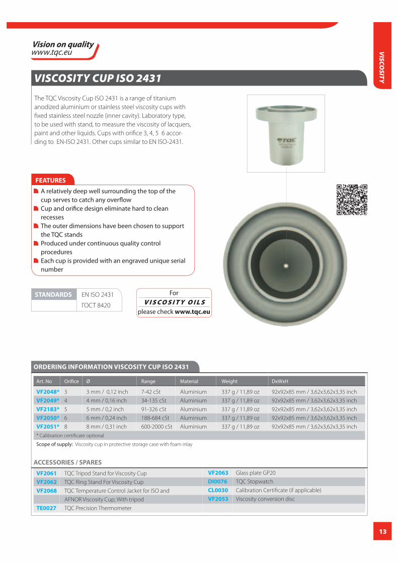
SITYVISCOSITY CUP ISO 2431
The TQC Viscosity Cup ISO 2431 is a range of titanium
anodized aluminium or stainless steel viscosity cups with
fi xed stainless steel nozzle (inner cavity). Laboratory type,
to be used with stand, to measure the viscosity of lacquers,
paint and other liquids. Cups with orifi ce 3, 4, 5 6 accor-
ding to EN-ISO 2431. Other cups similar to EN ISO-2431.
ORDERING INFORMATION VISCOSITY CUP ISO 2431
Art. No Orifi ce Ø Range Material Weight DxWxH
VF2048* 3 3 mm / 0,12 inch 7-42 cSt Aluminium 337 g / 11,89 oz 92x92x85 mm / 3,62x3,62x3,35 inch
VF2049* 4 4 mm / 0,16 inch 34-135 cSt Aluminium 337 g / 11,89 oz 92x92x85 mm / 3,62x3,62x3,35 inch
VF2183* 5 5 mm / 0,2 inch 91-326 cSt Aluminium 337 g / 11,89 oz 92x92x85 mm / 3,62x3,62x3,35 inch
VF2050* 6 6 mm / 0,24 inch 188-684 cSt Aluminium 337 g / 11,89 oz 92x92x85 mm / 3,62x3,62x3,35 inch
VF2051* 8 8 mm / 0,31 inch 600-2000 cSt Aluminium 337 g / 11,89 oz 92x92x85 mm / 3,62x3,62x3,35 inch
* Calibration certifi cate optional
Scope of supply: Viscosity cup in protective storage case with foam inlay
STANDARDS EN ISO 2431
ГОСТ 8420
FEATURES
A relatively deep well surrounding the top of the cup serves to catch any overfl ow Cup and orifi ce design eliminate hard to clean recesses The outer dimensions have been chosen to support the TQC stands Produced under continuous quality control procedures Each cup is provided with an engraved unique serial number
ACCESSORIES / SPARES
VF2061 TQC Tripod Stand for Viscosity Cup
VF2062 TQC Ring Stand For Viscosity Cup
VF2068 TQC Temperature Control Jacket for ISO and
AFNOR Viscosity Cup; With tripod
TE0027 TQC Precision Thermometer
VF2063 Glass plate GP20
DI0076 TQC Stopwatch
CL0030 Calibration Certifi cate (if applicable)
VF2053 Viscosity conversion disc
For
V I S C O S I T Y O I L S please check www.tqc.eu

14
VIS
COSI
TY
VISCOSITY CUP DIN 53211
The TQC Viscosity Cup DIN 53211 is a range of titanium
anodized aluminium or stainless steel viscosity cups with
fixed stainless steel nozzle (inner cavity). Laboratory type,
to be used with stand, to measure the viscosity of lacquers,
paint and other liquids. Cups with orifice 4 according to
DIN 53211. Other cups similar to DIN 53211.
ORDERING INFORMATION VISCOSITY CUP DIN 53211
Art. No Orifice Ø Range Material Weight DxWxH
VF2000 2 2 mm / 0,08 inch - Aluminium 212 g / 7,48 oz 92x92x75 mm / 3,62x3,62x2,95inch
VF2001 3 3 mm / 0,12 inch - Aluminium 212 g / 7,48 oz 92x92x75 mm / 3,62x3,62x2,95inch
VF1999* 4 4 mm / 0,16 inch 96-683 cSt Aluminium 212 g / 7,48 oz 92x92x75 mm / 3,62x3,62x2,95inch
VF2003 6 6 mm / 0,24 inch - Aluminium 212 g / 7,48 oz 92x92x75 mm / 3,62x3,62x2,95inch
VF2004 8 8 mm / 0,31 inch - Aluminium 212 g / 7,48 oz 92x92x75 mm / 3,62x3,62x2,95inch
VF2015* 4 4 mm / 0,16 inch 96-683 cSt St. Steel 605 g / 21,34 oz 92x92x75 mm / 3,62x3,62x2,95inch
* Calibration certificate optional
Scope of supply: Viscosity cup in protective storage case with foam inlay
STANDARDS DIN 53211
FEATURES
A relatively deep well surrounding the top of the cup serves to catch any overflow Cup and orifice design eliminate hard to clean recesses The outer dimensions have been chosen to support the TQC stands Produced under continuous quality control procedures Each cup is provided with an engraved unique serial number
ACCESSORIES / SPARES
VF2061 TQC Tripod Stand for Viscosity Cup
VF2062 TQC Ring Stand For Viscosity Cup
VF2067 TQC Temperature Control Jacket for Viscosity DIN and
ASTM Cup; with tripod
TE0027 TQC Precision Thermometer
VF2063 Glass plate GP20
DI0076 TQC Stopwatch
CL0030 Calibration Certificate (if applicable)
VF2053 Viscosity conversion disc
For
V I S C O S I T Y O I L S please check www.tqc.eu

15
VISCO
SITYVISCOSITY CUP ASTM D1200 ‘FORD’
The TQC Viscosity Cup ASTM D1200 ‘Ford’ is a range of
titanium anodized aluminium or stainless steel viscosity
cups with fixed stainless steel nozzle (inner cavity). Labora-
tory type, to be used with stand, to measure the viscosity
of lacquers, paint and other liquids. All cups according to
ASTM D1200.
FEATURES
A relatively deep well surrounding the top of the cup serves to catch any overflow Cup and orifice design eliminate hard to clean recesses The outer dimensions have been chosen to support the TQC stands Produced under continuous quality control procedures Each cup is provided with an engraved unique serial number
ORDERING INFORMATION VISCOSITY CUP ASTM D1200 ‘FORD’
Art. No Orifice Ø Range Material Weight DxWxH
VF2030* 2 2,53 mm / 0,1 inch 25-120 cSt Aluminium 195 g / 6,88 oz 92x92x77 mm / 3,62x3,62x 3,03 inch
VF2031* 3 3,40 mm / 0,13 inch 49-220 cSt Aluminium 195 g / 6,88 oz 92x92x77 mm / 3,62x3,62x 3,03 inch
VF2032* 4 4,12 mm / 0,16 inch 70-370 cSt Aluminium 195 g / 6,88 oz 92x92x77 mm / 3,62x3,62x 3,03 inch
VF2033* 5 5,2 mm / 0,2 inch 200-1200 cSt Aluminium 195 g / 6,88 oz 92x92x77 mm / 3,62x3,62x 3,03 inch
* Calibration certificate optional
Scope of supply: Viscosity cup in protective storage case with foam inlay
ACCESSORIES / SPARES
VF2061 TQC Tripod Stand for Viscosity Cup
VF2062 TQC Ring Stand For Viscosity Cup
VF2067 TQC Temperature Control Jacket for DIN and ASTM
Viscosity Cup; with tripod
TE0027 TQC Precision Thermometer
VF2063 Glass plate GP20
DI0076 TQC Stopwatch
CL0030 Calibration Certificate (if applicable)
VF2053 Viscosity conversion disc
STANDARDS ASTM D1200
For
V I S C O S I T Y O I L S please check www.tqc.eu

16
VIS
COSI
TY
VISCOSITY CUP AFNOR
The TQC Viscosity Cup AFNOR is a range of titanium ano-
dized aluminium viscosity cups with fixed stainless steel
nozzle (inner cavity). Laboratory type, to be used with
stand, to measure the viscosity of lacquers, paint and other
liquids. All cups according to AFNOR.
ORDERING INFORMATION VISCOSITY CUP AFNOR
Art. No Orifice Ø Range Material Weight DxWxH
VF2195 2,5 2,46 mm / 0,1 inch 5-140 cSt Aluminium 271 g / 9,56 oz 86x86x75 mm / 3,39x3,39x2,95 inch
VF2196 4 4 mm / 0,16 inch 50-1100 cSt Aluminium 271 g / 9,56 oz 86x86x75 mm / 3,39x3,39x2,95 inch
VF2197 6 6 mm / 0.24 inch 510-5100 cSt Aluminium 271 g / 9,56 oz 86x86x75 mm / 3,39x3,39x2,95 inch
VF2198 8 8 mm / 0,31 inch - Aluminium 271 g / 9,56 oz 86x86x75 mm / 3,39x3,39x2,95 inch
Scope of supply: Viscosity cup in protective storage case with foam inlay
STANDARDS NF T030-014
FEATURES
A relatively deep well surrounding the top of the cup serves to catch any overflow Cup and orifice design eliminate hard to clean recesses The outer dimensions have been chosen to support the TQC stands Produced under continuous quality control procedures Each cup is provided with an engraved unique serial number
ACCESSORIES / SPARES
VF2061 TQC Tripod Stand for Viscosity Cup
VF2062 TQC Ring Stand For Viscosity Cup
VF2068 TQC Temperature Control Jacket for ISO and AFNOR
Viscosity Cup; With tripod
TE0027 TQC Precision Thermometer
VF2063 Glass plate GP20
DI0076 TQC Stopwatch
VF2053 Viscosity conversion disc
For
V I S C O S I T Y O I L S please check www.tqc.eu

17
VISCO
SITYVISCOSITY CUP DIN 53211 WITH INTERCHANGEABLE NOZZLES
The TQC Viscosity Cup DIN 53211 with interchangeable
nozzle consists of a viscosity cup with a range of inter-
changeable nozzles. The special aluminium cup is fitted
with a stainless steel nozzle container. Stainless steel
nozzles are available from orifice 1 mm to orifice 8 mm, to
be ordered separately. Laboratory type, to be used with
stand, to measure the viscosity of lacquers, paint and other
liquids. Inner dimensions similar to DIN 53211.
ORDERING INFORMATION VISCOSITY CUP DIN 53211 WITH INTERCHANGEABLE NOZZLES
Art. No Orifice Ø Range Material Weight DxWxH
VF2020* - - - Aluminium cup / 215 g / 7,58 oz 92x92x75 mm / 3,62x3,62x2,95inch
St. steel retainer
VF2181 1 1 mm / 0,04 inch - St. steel 5 g / 0,18 oz 18 x 18 x 4 mm / 0,63x0,63x0,14 inch
VF2022 2 2 mm / 0,08 inch - St. steel 5 g / 0,18 oz 18 x 18 x 4 mm / 0,63x0,63x0,14 inch
VF2023 3 3 mm / 0,12 inch - St. steel 5 g / 0,18 oz 18 x 18 x 4 mm / 0,63x0,63x0,14 inch
VF2024* 4 4 mm / 0,16 inch 96-683 cSt St. steel 5 g / 0,18 oz 18 x 18 x 4 mm / 0,63x0,63x0,14 inch
VF2025 5 5 mm / 0,2 inch - St. steel 5 g / 0,18 oz 18 x 18 x 4 mm / 0,63x0,63x0,14 inch
VF2026 6 6 mm / 0,24 inch - St. steel 5 g / 0,18 oz 18 x 18 x 4 mm / 0,63x0,63x0,14 inch
* Calibration certificate optional
Viscosity cup in protective storage case with foam inlay. Nozzles to be ordered separately
FEATURES
Nozzles available with orifices from 1 to 8 mm A relatively deep well surrounding the top of the cup serves to catch any overflow Cup and orifice design eliminate hard to clean recesses The outer dimensions have been chosen to support the TQC stands Produced under continuous quality control procedures Each cup is provided with an engraved unique serial number
ACCESSORIES / SPARES
VF2061 TQC Tripod Stand for Viscosity Cup
VF2062 TQC Ring Stand For Viscosity Cup
VF2067 TQC Temperature Control Jacket for DIN and ASTM
Viscosity Cup; with tripod
TE0027 TQC Precision Thermometer
VF2063 Glass plate GP20
DI0076 TQC Stopwatch
CL0030 Calibration Certificate (if applicable)
VF2053 Viscosity conversion disc
STANDARDS According/similar to DIN 53211
For
V I S C O S I T Y O I L S please check www.tqc.eu

18
VIS
COSI
TY
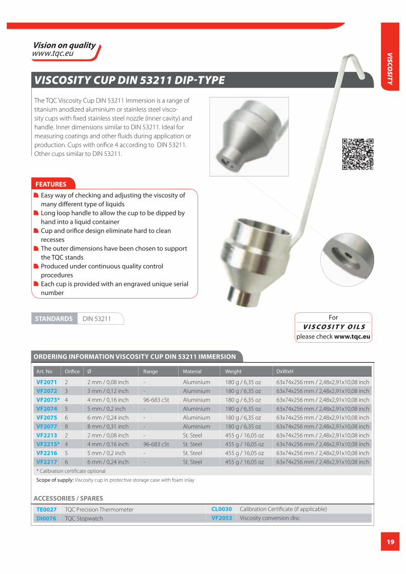
VISCOSITY CUP ISO 2431 DIP-TYPE
The TQC Viscosity Cup ISO 2431 Immersion is a range of ti-
tanium anodized aluminium or stainless steel viscosity cups
with fixed stainless steel nozzle (inner cavity) and handle.
Inner dimensions similar to ISO 2431. Ideal for measuring
coatings and other fluids during application or production.
Cups with orifice 3, 4, 5 6 according to EN-ISO 2431. Other
cups similar to EN-ISO 2431.
ORDERING INFORMATION VISCOSITY CUP ISO 2431 IMMERSION
Art. No Orifice Ø Range Material Weight DxWxH
VF2090* 3 3 mm / 0,12 inch 7-42 cSt Aluminium 283 g / 9,98 oz 63x102x256 mm / 2,48x4,02x10,08 inch
VF2091* 4 4 mm / 0,16 inch 34-135 cSt Aluminium 283 g / 9,98 oz 63x102x256 mm / 2,48x4,02x10,08 inch
VF2185* 5 5 mm / 0,2 inch 91-326 cSt Aluminium 283 g / 9,98 oz 63x102x256 mm / 2,48x4,02x10,08 inch
VF2092* 6 6 mm / 0,24 inch 188-684 cSt Aluminium 283 g / 9,98 oz 63x102x256 mm / 2,48x4,02x10,08 inch
VF2093* 8 8 mm / 0,31 inch 600-2000 cSt Aluminium 283 g / 9,98 oz 63x102x256 mm / 2,48x4,02x10,08 inch
VF2222* 4 4 mm / 0,16 inch 34-135 cSt St. steel 756 g / 26,67 oz 63x102x256 mm / 2,48x4,02x10,08 inch
* Calibration certificate optional
Scope of supply: Viscosity cup in protective storage case with foam inlay
FEATURES
Easy way of checking and adjusting the viscosity of many different type of liquids Long loop handle to allow the cup to be dipped by hand into a liquid container Cup and orifice design eliminate hard to clean recesses The outer dimensions have been chosen to support the TQC stands Produced under continuous quality control procedures Each cup is provided with an engraved unique serial number
ACCESSORIES / SPARES
TE0027 TQC Precision Thermometer
DI0076 TQC Stopwatch
CL0030 Calibration Certificate (if applicable)
VF2053 Viscosity conversion disc
STANDARDS EN-ISO 2431
ГОСТ 8420
For
V I S C O S I T Y O I L S please check www.tqc.eu
19
VISCO
SITYVISCOSITY CUP DIN 53211 DIP-TYPE
The TQC Viscosity Cup DIN 53211 Immersion is a range of
titanium anodized aluminium or stainless steel visco-
sity cups with fixed stainless steel nozzle (inner cavity) and
handle. Inner dimensions similar to DIN 53211. Ideal for
measuring coatings and other fluids during application or
production. Cups with orifice 4 according to DIN 53211.
Other cups similar to DIN 53211.
ORDERING INFORMATION VISCOSITY CUP DIN 53211 IMMERSION
Art. No Orifice Ø Range Material Weight DxWxH
VF2071 2 2 mm / 0,08 inch - Aluminium 180 g / 6,35 oz 63x74x256 mm / 2,48x2,91x10,08 inch
VF2072 3 3 mm / 0,12 inch - Aluminium 180 g / 6,35 oz 63x74x256 mm / 2,48x2,91x10,08 inch
VF2073* 4 4 mm / 0,16 inch 96-683 cSt Aluminium 180 g / 6,35 oz 63x74x256 mm / 2,48x2,91x10,08 inch
VF2074 5 5 mm / 0,2 inch - Aluminium 180 g / 6,35 oz 63x74x256 mm / 2,48x2,91x10,08 inch
VF2075 6 6 mm / 0,24 inch - Aluminium 180 g / 6,35 oz 63x74x256 mm / 2,48x2,91x10,08 inch
VF2077 8 8 mm / 0,31 inch - Aluminium 180 g / 6,35 oz 63x74x256 mm / 2,48x2,91x10,08 inch
VF2213 2 2 mm / 0,08 inch - St. Steel 455 g / 16,05 oz 63x74x256 mm / 2,48x2,91x10,08 inch
VF2215* 4 4 mm / 0,16 inch 96-683 cSt St. Steel 455 g / 16,05 oz 63x74x256 mm / 2,48x2,91x10,08 inch
VF2216 5 5 mm / 0,2 inch - St. Steel 455 g / 16,05 oz 63x74x256 mm / 2,48x2,91x10,08 inch
VF2217 6 6 mm / 0,24 inch - St. Steel 455 g / 16,05 oz 63x74x256 mm / 2,48x2,91x10,08 inch
* Calibration certificate optional
Scope of supply: Viscosity cup in protective storage case with foam inlay
FEATURES
Easy way of checking and adjusting the viscosity of many different type of liquids Long loop handle to allow the cup to be dipped by hand into a liquid container Cup and orifice design eliminate hard to clean recesses The outer dimensions have been chosen to support the TQC stands Produced under continuous quality control procedures Each cup is provided with an engraved unique serial number
ACCESSORIES / SPARES
TE0027 TQC Precision Thermometer
DI0076 TQC Stopwatch
CL0030 Calibration Certificate (if applicable)
VF2053 Viscosity conversion disc
STANDARDS DIN 53211 For
V I S C O S I T Y O I L S please check www.tqc.eu

20
VIS
COSI
TY
VISCOSITY CUP ASTM D1200 ‘FORD’ DIP-TYPE
The TQC Viscosity cup ASTM D1200 Immersion ‘Ford’ is a
range of titanium anodized aluminium or stainless steel
viscosity cups with fixed stainless steel nozzle (inner cavity)
and handle. Ideal for measuring coatings and other fluids
during application or production. All cups according to
ASTM D1200.
FEATURES
Easy way of checking and adjusting the viscosity of many different type of liquids Long loop handle to allow the cup to be dipped by hand into a liquid container Cup and orifice design eliminate hard to clean recesses The outer dimensions have been chosen to support the TQC stands Produced under continuous quality control procedures Each cup is provided with an engraved unique serial number
ORDERING INFORMATION VISCOSITY CUP ASTM D1200 IMMERSION ‘FORD’
Art. No Orifice Ø Range Material Weight DxWxH
VF2087* 4 4,12 mm / 0,16 inch 70-370 cSt Aluminium 174 g / 6,14 oz 63x90x255 mm / 2,48x3,54x10,04 inch
* Calibration certificate optional
Scope of supply: Viscosity cup in protective storage case with foam inlay
ACCESSORIES / SPARES
TE0027 TQC Precision Thermometer
DI0076 TQC Stopwatch
CL0030 Calibration Certificate (if applicable)
VF2053 Viscosity conversion disc
STANDARDS ASTM D1200
For
V I S C O S I T Y O I L S please check www.tqc.eu

21
VISCO
SITYVISCOSITY CUP ASTM D1084 / D4212 ‘ZAHN’ DIP-TYPE
The TQC Viscosity cup ASTM D1084 / D4212 Immersion
‘Zahn’ is a range stainless steel viscosity cups with fixed
stainless steel nozzle (inner cavity) and handle. Ideal for
measuring coatings and other fluids during application or
production. All cups according to ASTM D1084 and ASTM
D4212.
ORDERING INFORMATION VISCOSITY CUP ASTM D1084 / D4212 IMMERSION ‘ZAHN’
Art. No Orifice Ø Range Material Weight DxWxH
VF2226* 1 1,80 mm / 0,07 inch 0-60 cSt St. Steel 127 g / 4,48 oz 53x53x328 mm / 2,09x2,09x12,91 inch
VF2227* 2 2,70 mm / 0,11 inch 20-250 cSt St. Steel 127 g / 4,48 oz 53x53x328 mm / 2,09x2,09x12,91 inch
VF2228* 3 3,80 mm / 0,15 inch 100-800 cSt St. Steel 127 g / 4,48 oz 53x53x328 mm / 2,09x2,09x12,91 inch
VF2229* 4 4,30 mm / 0,17 inch 200-1200 cSt St. Steel 127 g / 4,48 oz 53x53x328 mm / 2,09x2,09x12,91 inch
VF2230* 5 5,30 mm / 0,21 inch 400-1800 cSt St. Steel 127 g / 4,48 oz 53x53x328 mm / 2,09x2,09x12,91 inch
* Calibration certificate optional
Scope of supply: Viscosity cup in protective storage case with foam inlay
FEATURES
Easy way of checking and adjusting the viscosity of many different type of liquids Long loop handle to allow the cup to be dipped by hand into a liquid container Cup and orifice design eliminate hard to clean recesses The outer dimensions have been chosen to support the TQC stands Produced under continuous quality control procedures Each cup is provided with an engraved unique serial number
ACCESSORIES / SPARES
TE0027 TQC Precision Thermometer
DI0076 TQC Stopwatch
VF2053 Viscosity conversion disc
CL0030 Calibration Certificate (if applicable)
STANDARDS ASTM D1084
ASTM D4212
For
V I S C O S I T Y O I L S please check www.tqc.eu

22
VIS
COSI
TY
FEATURES
Ideal for quick testing Each cup is provided with a unique serial number Easy to clean
RING STAND FOR VISCOSITY CUP
The TQC Ring Stand for Viscosity Cup is a ring stand made
of galvanized steel, suitable for all TQC Viscosity Cups
according DIN, ISO and ASTM.
FEATURES
Non-slip base Suitable for all TQC viscosity cups according Din, ISO and ASTM Easy to clean
Material legs stainless steel
Material galvanized steel
Dimensions (DxWxH) 150x150x253 mm / 5,91x5,91x9,96 inch
Weight 188 g / 6,63 oz
TECHNICAL SPECIFICATIONSTRIPOD STAND FOR VISCOSITY CUP
ORDERING INFORMATION TRIPOD STAND FOR VISCOSITY CUP
Art. No
VF2062 TQC Ring stand for viscosity cup
Scope of supply: TQC Ring stand
LORY CUP
The TQC Lory Cup is designed
for quick measurements on
location or during production
processes. The bottom of this
cup is provided with a small
gap as well as a needle point.
The product measured will
flow out of the small gap and
as soon as the needle point
appears during this process,
the flow time is determined.
ORDERING INFORMATION LORY CUP
Art. No
VF2199 TQC Lory Cup
Material legs steel
Material cup brass zinc plate
Dimensions (DxWxH) 170x49 mm / 6,69x1,92 inch
Weight 130 g / 5,99 oz
TECHNICAL SPECIFICATIONS LORY CUP
For
V I S C O S I T Y O I L S please check www.tqc.eu

23
VISCO
SITYTRIPOD STAND FOR VISCOSITY CUP
The TQC Tripod Stand for Viscosity Cup is a stand that is
easy to level with the adjustable feet of the unit and the
built-in spirit level. The ring is made of stainless steel, the
legs are made of stainless steel and the feet PVC. Suitable
for all DIN, ISO and ASTM viscosity beakers.
ORDERING INFORMATION TRIPOD STAND FOR VISCOSITY CUP
Art. No
VF2061 Tripod stand for viscosity cup
Scope of supply: Tripod stand. Built-in level indicator
FEATURES
All stainless steel Built-in spirit level Adjustable feet for easy leveling Non-slip base Suitable for all DIN, ISO, ASTM beakers
Material legs stainless steel
Material ring stainless steel
Material feet PVC
Dimensions(DxWxH) 95x95x262mm / 3,74x3,74x10,31 inch
Weight 694 g / 24,48 oz
TECHNICAL SPECIFICATIONS TRIPOD STAND FOR VISCOSITY CUP
24
VIS
COSI
TY
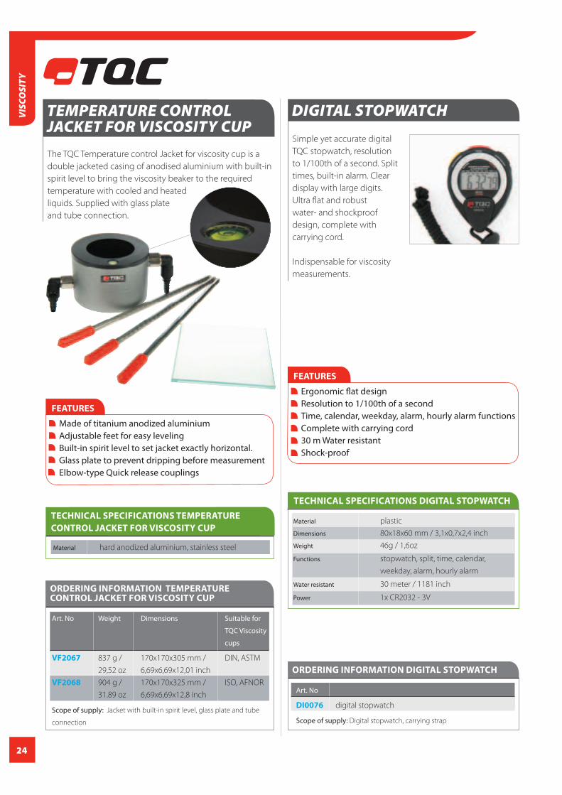
DIGITAL STOPWATCH
Simple yet accurate digital
TQC stopwatch, resolution
to 1/100th of a second. Split
times, built-in alarm. Clear
display with large digits.
Ultra flat and robust
water- and shockproof
design, complete with
carrying cord.
Indispensable for viscosity
measurements.
ORDERING INFORMATION DIGITAL STOPWATCH
Art. No
DI0076 digital stopwatch
Scope of supply: Digital stopwatch, carrying strap
Material plastic
Dimensions 80x18x60 mm / 3,1x0,7x2,4 inch
Weight 46g / 1,6oz
Functions stopwatch, split, time, calendar,
weekday, alarm, hourly alarm
Water resistant 30 meter / 1181 inch
Power 1x CR2032 - 3V
TECHNICAL SPECIFICATIONS DIGITAL STOPWATCH
FEATURES
Ergonomic flat design Resolution to 1/100th of a second Time, calendar, weekday, alarm, hourly alarm functions Complete with carrying cord 30 m Water resistant Shock-proof
The TQC Temperature control Jacket for viscosity cup is a
double jacketed casing of anodised aluminium with built-in
spirit level to bring the viscosity beaker to the required
temperature with cooled and heated
liquids. Supplied with glass plate
and tube connection.
TEMPERATURE CONTROL JACKET FOR VISCOSITY CUP
FEATURES
Made of titanium anodized aluminium Adjustable feet for easy leveling Built-in spirit level to set jacket exactly horizontal. Glass plate to prevent dripping before measurement Elbow-type Quick release couplings
Material hard anodized aluminium, stainless steel
TECHNICAL SPECIFICATIONS TEMPERATURE
CONTROL JACKET FOR VISCOSITY CUP
ORDERING INFORMATION TEMPERATURE CONTROL JACKET FOR VISCOSITY CUP
Art. No Weight Dimensions Suitable for
TQC Viscosity
cups
VF2067 837 g / 170x170x305 mm / DIN, ASTM
29,52 oz 6,69x6,69x12,01 inch
VF2068 904 g / 170x170x325 mm / ISO, AFNOR
31.89 oz 6,69x6,69x12,8 inch
Scope of supply: Jacket with built-in spirit level, glass plate and tube
connection
25
VISCO
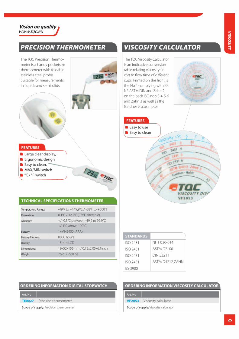
SITYVISCOSITY CALCULATOR
The TQC Viscosity Calculator
is an indicative conversion
table relating viscosity (in
cSt) to flow time of different
cups. Printed on the front is
the No.4 complying with BS
NF ASTM DIN and Zahn 2,
on the back ISO no.’s 3-4-5-6
and Zahn 3 as well as the
Gardner viscosimeter
ORDERING INFORMATION VISCOSITY CALCULATOR
Art. No
VF2053 Viscosity calculator
Scope of supply: Viscosity calculator
FEATURES
Easy to use Easy to clean
PRECISION THERMOMETER
The TQC Precision Thermo-
meter is a handy pocketsize
thermometer with foldable
stainless steel probe.
Suitable for measurements
in liquids and semisolids.
ORDERING INFORMATION DIGITAL STOPWATCH
Art. No
TE0027 Precision thermometer
Scope of supply: Precision thermometer
TECHNICAL SPECIFICATIONS THERMOMETER
FEATURES
Large clear display, Ergonomic design Easy to clean. MAX/MIN switch °C / °F switch
Temperature Range: -49,9 to +149,9°C / -58°F to +300°F
Resolution: 0.1°C / 32,2°F (C°/°F alterable)
Accuracy: +/- 0.5°C between -49,9 to 99,9°C,
+/-1°C above 100°C
Battery: 1xMN2400 (AAA)
Battery lifetime: 8000 hours
Display: 15mm LCD
Dimensions: 19x52x155mm / 0,75x2,05x6,1inch
Weight: 76 g / 2,68 oz
STANDARDS
ISO 2431
ISO 2431
ISO 2431
ISO 2431
BS 3900
NF T 030-014
ASTM D2100
DIN 53211
ASTM D4212 ZAHN

26
VIS
COSI
TY
AUTOMATIC KREBS VISCOMETER
The TQC Automatic Krebs Viscometer is widely used for de-
termination of the viscosity according to Krebs KU, as used
in the paint, coating and ink industry. The TQC Automatic
Krebs Viscometer is equipped with a clear display and easy
user interface that ensure highly reproducible results in
fully automatic measuring cycles.
The TQC Automatic Krebs Viscosity can be used automatic
and manually. In both modes waiting and measuring time
can be pre-set by the user between 0 and 99 seconds.
Results can be printed by means of a thermal printer and
serial communication RS232.
The meter is both highly accurate and simple to use,
making it suitable for research as well as production
environment.
STANDARDS ASTM D562
ASTM D1131
ASTM D856
ORDERING INFORMATION AUTOMATIC KREBS VISCOMETER
Art. No
DV1300 Automatic Krebs viscometer
Scope of supply: Main unit, spindle, power cord, pint can adapter, ½ pint can adapter, glass beaker, Allen key, Certificate
FEATURES
Easy to use Automatic or manual mode Automatic up/down spindle positioning Electrically driven Digital readout Auto stop
Measurement range 40.2 – 141 KU; 27 – 5274 cP
Accuracy 1% of full scale
Repeatability +/ 0.2%
Resolution 0.1 KU; 5cP
Operating temperature 10-40°C / 50-104°F
Rotation speed 200 min-1
Memory -
Languages EN
TECHNICAL SPECIFICATIONS AUTOMATIC KREBS VISCOMETER
Display yes
IP class IP20
Material sheet metal, stainless steel
Weight 8500 g / 18,74 lbs
Dimensions 325x190x500 mm / 12,8x7,48x19,69 inch
Power 100 – 240V 50 – 60 Hz
AUTO
CCICALIBRATION
CERTIFICATION
INCLUDED
27
VISCO
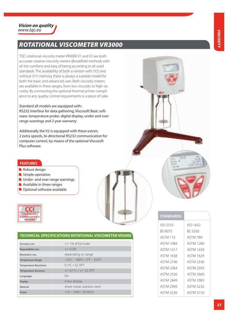
SITYROTATIONAL VISCOMETER VR3000
TQC rotational viscosity meter VR3000 V1 and V2 are both
accurate rotation viscosity meters (Brookfield method) with
all the comforts and easy of being according to all used
standards. The availability of both a version with (V2) and
without (V1) memory there is always a suitable model for
both the basic and advanced user. Both viscosity meters
are available in three ranges, from low viscosity to high vis-
cosity. By connecting the optional thermal printer compli-
ance to any quality control requirements is a piece of cake.
Standard all models are equipped with:RS232 interface for data gathering, Viscosoft Basic soft-ware, temperature probe, digital display, under and over range warnings and 2 year warranty
Additionally the V2 is equipped with these extra’s:2 extra speeds, bi-directional RS232 communication for computer control, by means of the optional Viscosoft Plus software.
FEATURES
Robust design Simple operation Under- and over range warnings Available in three ranges Optional software available
Accuracy visc +/- 1% of full scale
Repeatability visc +/- 0.2%
Resolution visc. depending on range
Temperature Range -15ºC – 180ºC / 5°F – 356°F
Temperature Resolution 0,1ºC / 32,18°F
Temperature Accuracy +/- 0,1ºC / +/- 32,18°F
Languages EN
Display 4 line display
Material sheet metal, stainless steel
Power 110 – 240V / 50-60Hz
TECHNICAL SPECIFICATIONS ROTATIONAL VISCOMETER VR3000
STANDARDS
ISO 2555 ISO 1652
BS 6075 BS 5350
ASTM 115 ASTM 789
ASTM 1084 ASTM 1286
ASTM 1417 ASTM 1439
ASTM 1638 ASTM 1824
ASTM 2196 ASTM 2336
ASTM 2364 ASTM 2393
ASTM 2556 ASTM 2669
ASTM 2849 ASTM 2983
ASTM 2994 ASTM 3232
ASTM 3236 ASTM 3716
CCICALIBRATION
CERTIFICATION
INCLUDED

28
VIS
COSI
TY
ORDERING INFORMATION ROTATIONAL VISCOMETER VR3000
Art. No DV1305 DV1306 DV1307 DV1308 DV1309 DV1310
Model V1 V1 V1 V2 V2 V2
Type L R H L R H
Supplied Spindles L1 – L4 R2 – R7 R2 – R7 L1 – L4 R2 – R7 R2 – R7
Speeds 0.3, 0.5, 0.6, 1, 1.5, 2, 2.5, 3, 4, 5, 6, 10, 12, 0.1, 0.2, 0.3, 0.5, 0.6, 1, 1.5, 2, 2.5, 3, 4,
20, 30, 50, 60, 100, 200 rpm (19 speeds) 5, 6, 10, 12, 20, 30, 50, 60, 100, 200 rpm (21 speeds)
Range With 3 – 2000000 20 – 13000000 1.6 – 106660 3 – 6000000 20 – 40000000 1.6 – 3200000
standard spindles mPas mPas dPas mPas mPas dPas
Displayable units mPas, cP, %, mPas, cP, % dPas, P, % mPas, cP, % mPas, cP, % dPas, P, %
Shearrate (SR) - - - 1/s
Shear Stress - - - N/m2, dyne/cm2
Suitable software ViscoBasic ViscoPlus
(optional)
Max per Spindle mPas mPas dPas mPas mPas dPas
L1 20000 - - 60000 - -
L2 - - 300000 - -
L3 400000 - - 1200000 - -
L4 2000000 - - 6000000 - -
R1 (optional) - 33300 2660 - 100000 8000
R2 - 133300 10600 - 400000 32000
R3 - 333300 26600 - 1000000 80000
R4 - 666600 53300 - 2000000 160000
R5 - 1300000 106000 - 3900000 320000
R6 - 3330000 266000 - 10000000 800000
R7 - 13300000 1060000 - 40000000 3200000
Range with Small 1.5 – 200000 25 – 3300000 2 – 266000 1.5 – 600000 25 – 10000000 2 – 800000
Sample Adapter mPas mPas dPas mPas mPas dPas
(optional)
Max per Spindle mPas mPas dPas mPas mPas dPas
TL5 10000 - - 30000 - -
increment 0.1 - - 0.1 - -
Sample vol 8.0 ml - - 8.0 ml - -
TL6 100000 - - 300000 - -
Increment 1 - - 1 - -
Sample vol 10.0 ml - - 10.0 ml - -
TL7 200000 - - 600000 - -
Increment 1 - - 1 - -
Sample vol 9.5 ml - - 9.5 ml - -

29
ORDERING INFORMATION ROTATIONAL VISCOMETER VR3000
Art. No DV1305 DV1306 DV1307 DV1308 DV1309 DV1310
TR8 - 166600 13000 - 500000 40000
Increment - 10 - - 10 -
Sample vol - 8.0 ml - 8.0 ml
TR9 - 833300 66600 - 2500000 200000
Increment - 100 - - 100 -
Sample vol - 10.5 ml - 10.5 ml
TR10 - 1600000 133000 - 5000000 400000
Increment - 100 - - 100 -
Sample vol - 11.5 ml - 11.5 ml
TR11 - 3300000 266000 - 10000000 800000
Increment - 100 - 100 -
Sample vol - 13.0 ml - 13.0 ml
Range with Low 0.3 – 2000 3.2 – 21333 0.25 – 1700 0.3 – 6000 3.2 – 64000 0.25 – 5120 Viscosity
Adapter mPas mPas dPas mPas mPas dPas
(optional)
Increments with Low 0.01 mPas 0.16 Mpas - 0.01 mPas 0.16 mPas -
Viscosity Adapter
Sample Volume 18 ml
Range with Adapter 156 – 3120000 1660 – 33300000 133 – 2660000 156 - 9400000 1660 – 100000000 133 – 8000000
for Helicoidal mPas mPas dPas mPas dPas
movement
Supplied Spindles PA, PB, PC, PD, PE, PF
Scope of supply: Visco meter, Stand for viscometer, Set of spindles (see specifications), Rack for spindles, Spindle guard, Temperature probe, Power cord,
Manual, Certificate
ACCESSORIES / SPARES
DV1311 R1 spindle
Optionally available: Helicodial drive unit. (DV1124); Small Sample, Adapter; Low Viscosity Adapter, Software available on request
VISCO
SITY

30
VIS
COSI
TY
ROTATIONAL VISCOMETER DV1400
TQC Rotational Viscometer according to Brookfield Method,
allows quick determination of viscosity in laboratory,
research centers, and during production. The intuitive, easy
functionality. light weight, and the fact they are battery
operated provide great versatility. TQC Rotational
Viscometer can even be used as a portable instrument.
Its main feature, compatibility to the Brookfield method,
allows comparative measurements with results obtained
in quality control laboratories using standard rotational
viscometers. (when used with the same spindle type and
the same rotational speed)
Two different models are available, one with a fixed speed
of 60rpm, the other one with a fixed speed of 20rpm.
FEATURES
Portable
Battery driven
Full spindle set
Results compatible with standard
rotational Viscometers
Suitcase included
Measurement range mPas
Accuracy +/- 2% of full scale
Repeatability +/- 1 %
Resolution R1,R2 1 mPas
Resolution R3, R4, R5 10 mPas
Resolution R6, R7 100 mPas
Memory none
Languages EN
Display 2 lines display
Material Sheet metal and
aluminium
Weight 1800 g / 63,5 oz
Dimensions 170x110x410 mm /
6,7x4,33x16,14 inch
(Without suitcase)
Power 4x AA battery
Autonomy 24 – 30 hours under
continuous operation
Operation temperature 10 – 40ºC / 50 – 122ºF
TECHNICAL SPECIFICATIONS
ROTATIONAL VISCOMETER DV1400
ORDERING INFORMATION ROTATIONAL VISCOMETER DV1400
Art. No DV1401 DV1402
Rotation speed 60 min-1 20 min-1
Range 66 – 66600 mPas 200 – 200000 mPas
R1 max (optional) 166 mPas 500 mPas
R2 max 660 mPas 2000 mPas
R3 max 1600 mPas 5000 mPas
R4 max 3300 mPas 10000 mPas
R5 max 6600 mPas 20000 mPas
R6 max 16600 mPas 50000 mPas
R7 max 66600 mPas 200000 mPas
ACCESSORIES / SPARES
DV1311 R1 spindle
Optionally available: Helicodial drive unit. (DV1124); Small Sample, Adapter;
Low Viscosity Adapter, Software available on request
CCICALIBRATION
CERTIFICATION
INCLUDED

31
VISCO
SITYVISCO THINNER
The TQC ViscoThinner offers a two instruments in one
option for material testing.
Easy continuous monitoring of the material viscosity during
the addition of solvents and thinners to create supply or
RFU viscosity. However uniquely the instrument also allows
definitive viscosity analysis at times pre-selected by the
user, providing excellent data relating to shear performance
and perfect for laboratory and factory applications.
The flexibility of this instrument allows the user the ultimate
control during the viscosity reduction pro-
cess whilst also providing very useful stability
analysis.
Operating based on a 3 spindle process
the standard lower spindle range has been
increased to allow testing levels of up to 25P,
alternative spindles can be added simply to
test beyond 25P.
Conforming to ISO 2884 and BS 3900 A7 can be purchased
as a single spindle option with additional spindles
and verifiable calibration oil kits.
ORDERING INFORMATION VISCO THINNER
Art. No
DV2000 Visco Thinner
STANDARDS
ISO 2884
BS 3900 A7
coming soon
CCICALIBRATION
CERTIFICATION
INCLUDED

32
FILM APPLICATIONFilm application in coating industry includes a broad
range of diff erent devices and instruments which are an
absolute necessity for testing or evaluation. Only in this
way the quality-related properties required can be tested,
compared, documented and communicated in compli-
ance with the requirements.
Film application covers a range of instruments that can
be divided in four groups:
Applicators
Applicator types come as Bird, Baker, Wire Bar, Micrometer
Casting Knife, Sag and Leveling, Stap Gap, Quadruplex,
Octoplex, Hand Proofer etc.. The choice depends on spec-
ifi cation or what one is accustomed to. Applicators vary in
width, single or multiple gap, clearance in either microns
or mils, hight adjustable or not, or wired in diff erent sizes.
The theoretical wet fi lm thickness is etched onto every
drawdown bar. The theoretical applied wet fi lm thickness
is roughly one-half the actual gap clearance. If you have
a gap clearance of 60 micron, the theoretical wet fi lm
thickness etched on the bar applicator is 30 micron. Due
to the many variables the drawdown is not guaranteed to
the theoretical fi lm thickness. Actual a variation of 50 to
90% in fi lm thickness is possible depending on gap clear-
ance. If the applicator is used manually variables in speed
and movement can cause an uneven drawdown. In these
cases we recommend an automatic fi lm applicator.
Application tables
To apply a uniform fi lm for examination a stable hard
surface is needed to make a good drawdown on test
charts with a high degree of reproducibility. The glass ap-
plication tables are equipped with a strong clamp to hold
down the charts and supplied with rubber top cover for
use with specifi c applicators.
Application machines
To prepare samples for testing rheological properties,
abrasion resistance, hiding power and gloss the TQC Au-
tomatic fi lm applicator is a must have. To apply a uniform
and reliable coating fi lm onto test charts, panels or foils
in order to eliminate variations caused by human factors
a automatic fi lm applicator is needed. Variations in speed,
pressure and direction of draw down cause irregularities,
those are elimminated by use of this type of applicator.
Other factors that may infl uence the result are the shear
rate and the weight of the applicator. With the automatic
fi lm applicator these variable factors are being stabilized.
Over the complete surface the fi lm thickness is even. The
TQC automatic fi lm applicator has all capabilities to use
any kind of applicators on any kind of test panel on chart
sizes A4, A5 and A6. A choice of glass table, vacuum table
perforated or canaled table, speed and length adjust-
ments are just a few features.
Test charts
For diff erent kind of tests on physical properties of paints,
lacquers or inks a wide range of consistent test charts
are developed. Those are suitable for determining hiding
power, opacity, spreading rate etc. They come in a variety
of dimensions from DIN A6 up to and including DIN A4.
Most charts are fi lm laminated for an excellent solvent
and chemical resistance and an even fi lm spread. Others
are uncoated for brushout to simulate wood or wallboard
and plastic polyester fi lms for wash and scrub testing.
FILM
APP
LICA
TIO
N

33
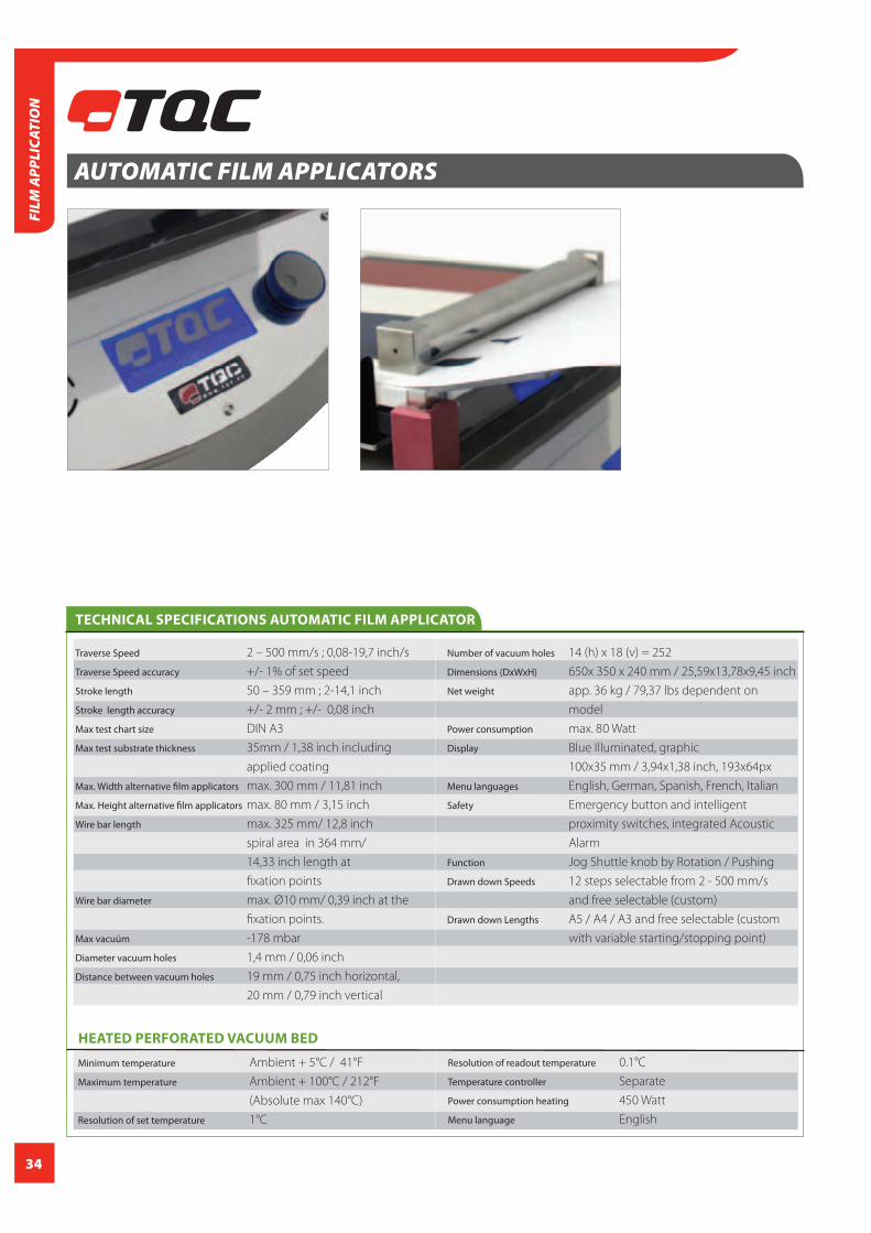
AUTOMATIC FILM APPLICATORS
The TQC Motorized Automatic fi lm applicator or drawdown
machine provides a reliable basis to apply coating fi lms to
test charts, panels or foils in a uniform and reprodu-
cible way in order to eliminate variations caused by human
factors. Variations in speed, pressure and direction of draw
down cause irregularities. Other factors that may infl uence
the result are the shear rate and the weight of the applica-
tor. With the TQC Automatic fi lm applicator these variable
factors are being stabilised. Over the complete surface the
fi lm thickness is even.
To prepare samples for testing rheological properties, abra-
sion resistance, hiding power and gloss the TQC Motorized
Automatic fi lm applicator is a must have. Motorized Film
Applicators are also used in the adhesives industry.
FEATURES
Digital setting of speed, start position, stop position and stroke length Wide speed range of 0-500 mm/s Silent built-in vacuum pump with selected models with vacuum bed Electronic vacuum area (A4/A3) selection eliminates the need for taping holes Tool carrier height can be increased to allow coating of thicker panels / samples
1. Display with process information
2. Jog Shuttle
3. Emergency button
4. Acoustic alarm / Buzzer
Vacuum bed or glass bed can removed without tools for cleaning Automatic spiral bar-coater retriever Extensive safety measures through emergency stop and proximity sensors complies with all relevant standards Optional drying time recorder to convert into a drying time recorder Also available with electrically heated vacuumbed
5. Levelling supports
6. Glass plate or Vacuum table
7. Automated clamping device for test charts
8. Mains connection
3 4 1 2 5 911 10 6 8 7
9. Applicator tool carrier
10. Spiral bar release device
11. Hand protection device
FILM A
PPLICATION
34
FILM
APP
LICA
TIO
N
AUTOMATIC FILM APPLICATORS
Traverse Speed 2 – 500 mm/s ; 0,08-19,7 inch/s
Traverse Speed accuracy +/- 1% of set speed
Stroke length 50 – 359 mm ; 2-14,1 inch
Stroke length accuracy +/- 2 mm ; +/- 0,08 inch
Max test chart size DIN A3
Max test substrate thickness 35mm / 1,38 inch including
applied coating
Max. Width alternative film applicators max. 300 mm / 11,81 inch
Max. Height alternative film applicators max. 80 mm / 3,15 inch
Wire bar length max. 325 mm/ 12,8 inch
spiral area in 364 mm/
14,33 inch length at
fixation points
Wire bar diameter max. Ø10 mm/ 0,39 inch at the
fixation points.
Max vacuüm -178 mbar
Diameter vacuum holes 1,4 mm / 0,06 inch
Distance between vacuum holes 19 mm / 0,75 inch horizontal,
20 mm / 0,79 inch vertical
TECHNICAL SPECIFICATIONS AUTOMATIC FILM APPLICATOR
Number of vacuum holes 14 (h) x 18 (v) = 252
Dimensions (DxWxH) 650x 350 x 240 mm / 25,59x13,78x9,45 inch
Net weight app. 36 kg / 79,37 lbs dependent on
model
Power consumption max. 80 Watt
Display Blue Illuminated, graphic
100x35 mm / 3,94x1,38 inch, 193x64px
Menu languages English, German, Spanish, French, Italian
Safety Emergency button and intelligent
proximity switches, integrated Acoustic
Alarm
Function Jog Shuttle knob by Rotation / Pushing
Drawn down Speeds 12 steps selectable from 2 - 500 mm/s
and free selectable (custom)
Drawn down Lengths A5 / A4 / A3 and free selectable (custom
with variable starting/stopping point)
HEATED PERFORATED VACUUM BED
Minimum temperature Ambient + 5°C / 41°F
Maximum temperature Ambient + 100°C / 212°F
(Absolute max 140°C)
Resolution of set temperature 1°C
Resolution of readout temperature 0.1°C
Temperature controller Separate
Power consumption heating 450 Watt
Menu language English

35
ORDERING INFORMATION AUTOMATIC FILM APPLICATORS
Art. No Power Bed
AB3120 230 V | 50 Hz Glass
AB3125 110 V-120V | 50/60 Hz Glass
AB3320 230 V | 50 Hz Perforated vacuum
AB3225 110 V-120V | 50/60 Hz Perforated vacuum
AB3220 230 V | 50 Hz Double channelled vacuum
AB3325 110 V-120V | 50/60 Hz Double channelled vacuum
AB3400 230 V | 50 Hz Heated vacuum
AB3405 110 V-120V | 50/60 Hz Heated vacuum
ACCESSORIES / SPARES
AB3500 TQC Drying time recorder tool (Only suitable for
models with firmware version 2.01 or above)
AB3000 Rubber placemat for TQC automatic film
applicator
AB3100 Glass table for automatic film applicator
AB3200 Perforated vacuum plate
AB3300 Double channelled vacuum plate
AB3028 Flexible LED light
All types and styles of applicators can be used such as wire wound rods or spiral bar
coaters, doctor blades. Bird-, or Baker type applicators, Quadruplex, or film casting
knife applicators.
Scope of supply: Motorized automatic film applicator, Rubber mat (only with glass
plate), Certificate of Conformance, Flexible LED light, English manual, Power cord
FILM A
PPLICATION
Heated Vacuumbed
The TQC Automatic film applicator
is also available with an electrically
heated vacuumbed. The temperature
can be set digitally from ambient
+5°C to ambient + 100°C . Heat-up
time is short and temperature is
uniform over the entire bed.

36
FILM
APP
LICA
TIO
N
DRYING TIME RECORDER ATTACHMENT
Drying Time Recorder tool to be used as an optional test
tool for the TQC Automatic Film Applicators. This device
allows the user to accurately define the drying time of vari-
ous types of coatings within the time range of 1 minute to
48 hours.
The drying time recorder option can be easily clamped on
any standard TQC Automatic film applicator with firmware
2.01 and above.
ORDERING INFORMATION DRYING TIME RECORDER OPTION
Art. No
AB3500 Drying time recorder option for TQC Automatic Film Applicators
Scope of supply: Drying time recorder option (without TQC Automatic Film Applicator)
ACCESSORIES / SPARES
AB3120 TQC motorized automatic film applicator 230V with glass bed
AB3220 TQC motorized automatic film applicator 230V with perforated vacuum bed, built-in vacuum pump
AB3320 TQC motorized automatic film applicator 230V with double channelled vacuum bed, built-in vacuum pump
AB3125 TQC motorized automatic film applicator 110V with glass bed
AB3225 TQC motorized automatic film applicator 110V with perforated vacuum bed, built-in vacuum pump
AB3325 TQC motorized automatic film applicator 110V with double channelled vacuum bed, built-in vacuum pump
AB3400 TQC motorized automatic film applicator 230V with heated vacuum bed, built-in vacuum pump
AB3405 TQC motorized automatic film applicator 100V with heated vacuum bed, built-in vacuum pump
FEATURES
Digital indication of the drying stages; From hand dry to dry in 10 seconds accurately displayed “Intelligent recording”, which significantly improves the resolution of a longer drying process.
STANDARDS ISO 9117-4
Material aluminium, stainless steel
Dimensions 60,5x315x50 mm /
2,38x12,4x1,97 inch
Weight 280 g / 9,88 oz
Drying time range 1 min. – 2880 min (48 hours)
Time accuracy ≤ 1% of set time.
Maximum test length 350mm / 13,78 inch
Maximum number of tracks 8
TECHNICAL SPECIFICATIONS DRYING TIME RECORDER
37
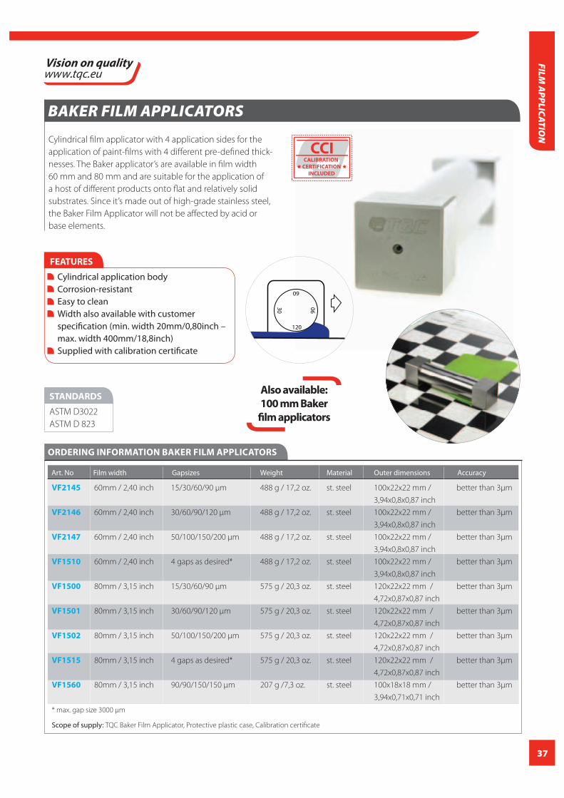
BAKER FILM APPLICATORS
Cylindrical film applicator with 4 application sides for the
application of paint-films with 4 different pre-defined thick-
nesses. The Baker applicator’s are available in film width
60 mm and 80 mm and are suitable for the application of
a host of different products onto flat and relatively solid
substrates. Since it’s made out of high-grade stainless steel,
the Baker Film Applicator will not be affected by acid or
base elements.
FEATURES
Cylindrical application body Corrosion-resistant Easy to clean Width also available with customer specification (min. width 20mm/0,80inch – max. width 400mm/18,8inch) Supplied with calibration certificate
STANDARDS
ASTM D3022
ASTM D 823
ORDERING INFORMATION BAKER FILM APPLICATORS
Art. No Film width Gapsizes Weight Material Outer dimensions Accuracy
VF2145 60mm / 2,40 inch 15/30/60/90 μm 488 g / 17,2 oz. st. steel 100x22x22 mm / better than 3μm
3,94x0,8x0,87 inch
VF2146 60mm / 2,40 inch 30/60/90/120 μm 488 g / 17,2 oz. st. steel 100x22x22 mm / better than 3μm
3,94x0,8x0,87 inch
VF2147 60mm / 2,40 inch 50/100/150/200 μm 488 g / 17,2 oz. st. steel 100x22x22 mm / better than 3μm
3,94x0,8x0,87 inch
VF1510 60mm / 2,40 inch 4 gaps as desired* 488 g / 17,2 oz. st. steel 100x22x22 mm / better than 3μm
3,94x0,8x0,87 inch
VF1500 80mm / 3,15 inch 15/30/60/90 μm 575 g / 20,3 oz. st. steel 120x22x22 mm / better than 3μm
4,72x0,87x0,87 inch
VF1501 80mm / 3,15 inch 30/60/90/120 μm 575 g / 20,3 oz. st. steel 120x22x22 mm / better than 3μm
4,72x0,87x0,87 inch
VF1502 80mm / 3,15 inch 50/100/150/200 μm 575 g / 20,3 oz. st. steel 120x22x22 mm / better than 3μm
4,72x0,87x0,87 inch
VF1515 80mm / 3,15 inch 4 gaps as desired* 575 g / 20,3 oz. st. steel 120x22x22 mm / better than 3μm
4,72x0,87x0,87 inch
VF1560 80mm / 3,15 inch 90/90/150/150 μm 207 g /7,3 oz. st. steel 100x18x18 mm / better than 3μm
3,94x0,71x0,71 inch
* max. gap size 3000 μm
Scope of supply: TQC Baker Film Applicator, Protective plastic case, Calibration certificate
FILM A
PPLICATION
CCICALIBRATION
CERTIFICATION
INCLUDED
60
120
90
30
Also available:
100 mm Baker
film applicators

38
FILM
APP
LICA
TIO
N
4-SIDED FILM APPLICATORS (QUADRUPLEX)
The TQC 4-Sided Film Applicator (Quadruplex) has
four application sides for applying paint fi lms with
four diff erent predefi ned thicknesses, in fi lm width
60 or 80 mm. One side of the applicator is supplied
with a guidance support for straight application.
This support may be removed as well. The high
grade stainless steel will not be
aff ected by acid or base elements.
FEATURES
4 application sides Corrosion-resistant Easy to clean Width also available with customer specifi cation (min. width 1mm/0,04inch – max. width 130mm/5,12inch) Supplied with calibration certifi cate
STANDARDS
ASTM D1084
ORDERING INFORMATION 4-SIDED FILM APPLICATORS (QUADRUPLEX)
Art. No Film width Gapsizes Weight Material Outer dimensions Accuracy
VF2167 60mm / 2,40 inch Gaps as desired* 100 g / 3,5 oz. st. steel 100x22x22 mm / better than 3μm
3,94x0,8x0,87 inch
VF2168 60mm / 2,40 inch 15/30/60/90 μm 100 g / 3,5 oz. st. steel 100x22x22 mm / better than 3μm
3,94x0,8x0,87 inch
VF2169 60mm / 2,40 inch 30/60/90/120 μm 100 g / 3,5 oz. st. steel 100x22x22 mm / better than 3μm
3,94x0,8x0,87 inch
VF2170 60mm / 2,40 inch 50/100/150/200μm 100 g / 3,5 oz. st. steel 100x22x22 mm / better than 3μm
3,94x0,8x0,87 inch
VF2172 80mm / 3,15 inch Gaps as desired* 130 g / 4,6 oz. st. steel 120x22x22 mm / better than 3μm
4,72x0,87x0,87 inch
VF2173 80mm / 3,15 inch 15/30/60/90 μm 130 g / 4,6 oz. st. steel 120x22x22 mm / better than 3μm
4,72x0,87x0,87 inch
VF2174 80mm / 3,15 inch 30/60/90/120 μm 130 g / 4,6 oz. st. steel 120x22x22 mm / better than 3μm
4,72x0,87x0,87 inch
VF2175 80mm / 3,15 inch 50/100/150/200 μm 130 g / 4,6 oz. st. steel 120x22x22 mm / better than 3μm
4,72x0,87x0,87 inch
VF2179 2 x 60mm / 2,40 inch 2 x 100/200/300/400 μm 214 g / 7,5 oz. st. steel 20x27x167 mm / better than 3μm
0,79x1,06x6,57 inch
* max. gap size 3000 μm
Scope of supply: TQC 4-sided Film Applicator (quadruplex), Protective plastic case, Calibration certifi cate
CCICALIBRATION
CERTIFICATION
INCLUDED

39
PRISM FILM APPLICATORS
TQC Prism film applicator with flat edges. Four application
sides for applying 4 different pre-defined thicknesses. The
TQC Prism applicator is available in film width 50, 75 and
100mm and suitable for applying a host of different
products onto flat and relatively solid substrates. The
high-grade stainless steel will not be affected by acid or
base elements.
We can give no guarantee of the wet thickness that will be
obtained. The wet thickness is dependent upon the solids
and vehicle content of the wet material as well as other fac-
tors. Film thickness deposited may vary from 40% to 80% of
the actual gate clearance of the TQC Prism applicator.
FEATURES
Either 1 or 4 clearances Flat edged prism body Corrosion-resistant Easy to clean Width also available with customer specification
ORDERING INFORMATION PRISM FILM APPLICATORS
Art. No Film width Gapsizes Weight Material Outer dimensions Accuracy
VF2161 50 mm / 2,0 inch 50/100/150/200 μm 410 g / 14,5 oz. st. steel 90x28x28 mm / better than 3 μm
3,54x1,1x1,1 inch
VF1837 50 mm / 2,0 inch 4 gaps as desired 410 g / 14,5 oz. st. steel 90x28x28 mm / better than 3 μm
3,54x1,1x1,1 inch
VF1540 50 mm / 2,0 inch 1 gap as desired 212 g / 7,48 oz st. steel 80x25x15 mm / better than 3 μm
3,15x0,98x0,59 inch
VF1541 50 mm / 2,0 inch 50 μm 212 g / 7,48 oz st. steel 80x25x15 mm / better than 3 μm
3,15x0,98x0,59 inch
VF1542 50 mm / 2,0 inch 75 μm 212 g / 7,48 oz st. steel 80x25x15 mm / better than 3 μm
3,15x0,98x0,59 inch
VF1543 50 mm / 2,0 inch 100 μm 212 g / 7,48 oz st. steel 80x25x15 mm / better than 3 μm
3,15x0,98x0,59 inch
VF1544 50 mm / 2,0 inch 125 μm 212 g / 7,48 oz st. steel 80x25x15 mm / better than 3 μm
3,15x0,98x0,59 inch
VF1545 50 mm / 2,0 inch 150 μm 212 g / 7,48 oz st. steel 80x25x15 mm / better than 3 μm
3,15x0,98x0,59 inch
VF1546 50 mm / 2,0 inch 200 μm 212 g / 7,48 oz st. steel 80x25x15 mm / better than 3 μm
3,15x0,98x0,59 inch
VF2164 60 mm / 2,36 inch 4 gaps as desired 352 g /12,42 oz st. steel 75x28x28 mm / better than 3 μm
2,95x1,1x1,1 inch
VF2162 75 mm / 3,0 inch 50/100/150/200 μm 495 g / 17,4 oz. st. steel 90x28x28 mm / better than 3 μm
3,54x1,1x1,1 inch
FILM A
PPLICATION
CCICALIBRATION
CERTIFICATION
INCLUDED
STANDARDS
ASTM D1084

40
FILM
APP
LICA
TIO
N
ORDERING INFORMATION PRISM FILM APPLICATORS
Art. No Film width Gapsizes Weight Material Outer dimensions Accuracy
VF1530 75 mm / 3,0 inch 4 gaps as desired 495 g / 17,4 oz. st. steel 90x28x28 mm / better than 3 μm
3,54x1,1x1,1 inch
VF1570 75 mm / 3,0 inch 1 gap as desired 275 g / 9,7 oz st. steel 105x25x15 mm / better than 3 μm
4,13x0,98x0,59 inch
VF1571 75 mm / 3,0 inch 50 μm 275 g / 9,7 oz st. steel 105x25x15 mm / better than 3 μm
4,13x0,98x0,59 inch
VF1572 75 mm / 3,0 inch 75 μm 275 g / 9,7 oz st. steel 105x25x15 mm / better than 3 μm
4,13x0,98x0,59 inch
VF1573 75 mm / 3,0 inch 100 μm 275 g / 9,7 oz st. steel 105x25x15 mm / better than 3 μm
4,13x0,98x0,59 inch
VF1574 75 mm / 3,0 inch 125 μm 275 g / 9,7 oz st. steel 105x25x15 mm / better than 3 μm
4,13x0,98x0,59 inch
VF1575 75 mm / 3,0 inch 150 μm 275 g / 9,7 oz st. steel 105x25x15 mm / better than 3 μm
4,13x0,98x0,59 inch
VF1576 75 mm / 3,0 inch 200 μm 275 g / 9,7 oz st. steel 105x25x15 mm / better than 3 μm
4,13x0,98x0,59 inch
VF1536 80 mm / 3,15 inch 4 gaps as desired 514 g / 18,13 oz st. steel 95x28x28 mm / better than 3 μm
3,74x1,1x1,1 inch
VF2163 100 mm / 4,0 inch 50/100/150/200 μm 585 g / 20,6 oz st. steel 140x28x28 mm / better than 3 μm
5,51x1,1x1,1 inch
VF1535 100 mm / 4,0 inch 4 gaps as desired 585 g / 20,6 oz st. steel 140x28x28 mm/ better than 3 μm
5,51x1,1x1,1 inch
VF1580 150 mm 4 gaps as desired st. steel better than 3 mm
VF1581 150 mm 50/100/150/200μm st. steel better than 3 mm
Scope of supply: TQC Prism film applicators single gap 50mm or 75mm, Plastic Protective Case, Calibration certificate

41
FILM A
PPLICATION
MICROMETER FILM APPLICATORS
Adjustable Micrometer Film Applicator with stainless steel
blade, aluminum frame and chrome thimbles and barrels.
The detachable blade makes cleaning easy. Also, this
Micrometric Film Applicator isn’t supplied with springs
which can break, rust or get clogged.
FEATURES
No springs to break, rust or get clogged Detachable blades for easy cleaning Enhanced accuracy Ergonomic design facilitates fast, accurate draw downs Replacement blades are easy to install & calibrate
STANDARDS
ASTM D 823
ORDERING INFORMATION MICROMETER FILM APPLICATORS
Art. No Art. No
LD3570 Micrometric film applicator 75 mm / 2,95 inch wide
LD3571 Micrometric film applicator 100 mm / 3,94 inch wide
LD3573 Micrometric film applicator 150 mm / 5,9 inch wide
LD3572 Micrometric film applicator 200 mm / 7,87 inch wide
TECHNICAL SPECIFICATIONSMICROMETER FILM APPLICATORS
Material Stainless Steel, Aluminium and Chrome
Weight 933 g / 33oz
Dimensions 21,6x10x10,8 mm/ 8.5x3.9x4.3 inch
Film thickness Adjustable between 0-6,35 mm
Increment 0,01 mm
8-SIDED FILM APPLICATOR OCTOPLEX
Multifunctional film applicator with 8 application sides for
application paint-films of 8 different pre-defined thick-
nesses. Since it’s made out of high-grade stainless steel, the
Octoplex will not be affected by acid or base elements
Clearance height / gaps 25,50,75,100,125,150,175,200μm
Clearance width 60 mm
Accuracy better than 3 micron
Material high grade stainless steel
Weight 147 g / 5,19 oz
Dimensions 85x85x11 mm / 3,35x3,35x0,43 inch
TECHNICAL SPECIFICATIONS8-SIDED FILM APPLICATOR OCTOPLEX
STANDARDS
ASTM D 3022
ASTM D 823
FMTS 141a
FMTS 2161
FMTS 2162
FMTS 4255
FMTS 6226
ORDERING INFORMATION 8-SIDED FILM APPLICATOR OCTOPLEX
Art. No
VF1550 8-sided film applicator octoplex
Scope of supply: TQC Octoplex film applicator, protective case, calibration certificate
CCICALIBRATION
CERTIFICATION
INCLUDED
42
FILM
APP
LICA
TIO
N
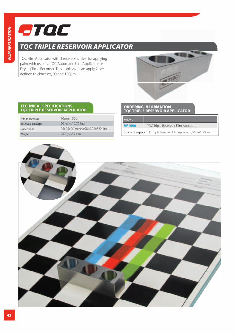
TQC TRIPLE RESERVOIR APPLICATOR
TQC Film Applicator with 3 reservoirs. Ideal for applying
paint with use of a TQC Automatic Film Applicator or
Drying Time Recorder. This applicator can apply 2 pre-
defi ned thicknesses, 90 and 150μm.
Film thicknesses 90μm, 150μm
Reservoir diameter 20 mm / 0,79 inch
Dimensions 25x25x90 mm/0,98x0,98x3,54 inch
Weight 247 g / 8,71 oz
TECHNICAL SPECIFICATIONSTQC TRIPLE RESERVOIR APPLICATOR
ORDERING INFORMATION TQC TRIPLE RESERVOIR APPLICATOR
Art. No
VF1590 TQC Triple Reservoir Film Applicator
Scope of supply: TQC Triple Reservoir Film Applicator, 90μm/150μm

43
TEST CHARTS
A wide range of consistent test charts for testing physical properties of coating, lacquers
and inks. Suitable for determining hiding power, opacity and spreading rate. They come in a
variety of dimensions from DIN A6 up to and including DIN A3. All charts are film laminated
for an excellent solvent and chemical resistance and an even film spread.
On each chart there is a section for filling out the date, time and test number.
Special designs are possible with quantities over 10.000 pieces per design.
Made in The Netherlands
T E S T C H A R T Applicator
System
Notiz/Notes
Datum/Date
Zeit/Time
Charge-Nr./No.
www.tqc.euArt. No. VF2347 Batch No.
T E S T C H A R TApplicator
SystemNotiz/Notes
Datum/DateZeit/Time
Charge-Nr./No.
www.tqc.euMade in The Netherlands
Art. No. VF2343 Batch No.
Made in The Netherlands
T E S T C H A R T Applicator
System
Notiz/Notes
Datum/Date
Zeit/Time
Charge-Nr./No.
www.tqc.euArt. No. VF2354 Batch No.
ORDERING INFORMATION TEST CHARTS
Art. No size Optical Pieces Design
brightener per set
VF2354 A3 297x420mm / yes * 250
16,54x11,69 inch
VF2345 A4 210x297 mm / yes * 250
11,69x8,27 inch
VF2347 A4 210x297 mm / yes * 250
11,69x8,27 inch
VF2321 A4 210x297 mm / no 250
11,69x8,27 inch
VF2325 A4 210x297 mm / no 250
11,69x8,27 inch
VF2344 A5 148x210 mm / yes * 250
8,27x5,83 inch
VF2346 A5 148x210 mm / yes * 250
8,27x5,83 inch
VF2319 A5 148x210 mm / no 250
8,27x5,83 inch
VF2323 A5 148x210 mm / no 250
8,27x5,83 inch
VF2343 A6 105x148 mm / yes * 250
5,83x4,13 inch
VF2317 A6 105x148 mm / no 250
5,83x4,13 inch
Scope of supply: Set of 250 pieces, with certificate
* Certificate only available for charts with optical brightner
T E S T C H A R T Applicator
System
Notiz/Notes
Datum/Date
Zeit/Time
Charge-Nr./No.
www.tqc.eu Made in The NetherlandsArt. No. VF2345 Batch No.
Made in The Netherlands
T E S T C H A R T Applicator
System
Notiz/Notes
Datum/Date
Zeit/Time
Charge-Nr./No.
www.tqc.euArt. No. VF2347 Batch No.
T E S T C H A R T Applicator
System
Notiz/Notes
Datum/Date
Zeit/Time
Charge-Nr./No.
www.tqc.eu Made in The NetherlandsArt. No. VF2343 Batch No.
FEATURES
- With certificate *- Excellent solvent - Chemical resistant- Even film spread Note section
ACCESSORIES / SPARES
VF1602 TQC Glass Film Application Table,
230 x 160 mm / 9,06x6,3 inch
VF1603 TQC Glass Film Application Table,
300 x 100 mm / 11,81x3,94 inch
VF1601 TQC Glass Film Application Table,
380 x 230 mm / 14,96x9,06 inch
ORDERING INFORMATION TEST CHARTS
FILM A
PPLICATION
CCICALIBRATION
CERTIFICATION
INCLUDED

44
TEST PANELS
TQC Panels are available in a large variety of dimensions,
materials and thicknesses. Use of TQC Test panels enhances
reproducibility of physical and chemical tests.
Each panel is equipped with a hole for hanging and
handling.
Not only standard test panels are available. Special dimen-
sions to customers specifi cations are possible as well.
FEATURES
Available in large varieties of dimensions, materials and thickness Each panel equipped with hole for hanging and handling
ORDERING INFORMATION TEST PANELS
Art. No Material Type Dimensions Qty
VF8523 Aluminium degreased & cleaned 75 x 150 x 0,8 mm / 2,95 x 5,9 x 0,032 inch 500
VF8522 Aluminium degreased & cleaned 50 x 100 x 0,8 mm / 1,97 x 3,94 x 0,032 inch 1800
VF8518 Aluminium degreased & cleaned 100 x 300 x 0,5 mm / 3,94 x 11,81 inch 300
VF8517 Steel degreased & cleaned 150 x 250 x 0,15 mm/ 5,9 x 9,84 x 0,006 inch 450
VF8516 Steel degreased & cleaned 60 x 140 x 0,5 mm/ 2,36 x 5,5 x 0,02 inch 600
VF8515 Steel Harmonic degreased 120 x 200 x 0,15 mm / 4,7 x 7,87 x 0,006 inch 700
& cleaned
VF8533 Aluminium degreased & cleaned 60 x 140 x 0,6 mm / 2,36 x 5,5 x 0,02 inch 900
VF8525 Aluminium chromated Alodine 1000 75 x 150 x 0,8 mm / 2,95 x 5,9 x 0,032 inch 500
VF8524 Aluminium chromated Alodine 1200 75 x 150 x 0,8 mm / 2,95 x 5,9 x 0,032 inch 500
VF8521 Aluminium degreased & cleaned 200 x 300 x 0,6 mm / 7,87 x 11,81 x 2,36 inch 150
VF8520 Aluminium PVC protection 200 x 300 x 0,6 mm / 7,87 x 11,81 x 2,36 inch 150
VF8519 Aluminium mirror polished- 60 x 140 x 0,5 mm / 2,36 x 5,5 x 0,02 inch 500
PVC protect
VF8511 Steel Smooth degreased & cleaned 75 x 150 x 0,5 mm / 2,95 x 5,9 x 0,02 inch 400
VF8510 Steel Smooth degreased & cleaned 60 x 200 x 0,5 mm / 2,36 x 7,87 x 0,02 inch 400
VF8513 Steel Matt degreased & cleaned 75 x 150 x 0,8 mm / 2,95 x 5,9 x 0,032 inch 300
VF8512 Steel Smooth degreased & cleaned 100 x 200 x 0,5 mm / 3,94 x 7,87 x 0,02 inch 250
VF8526 Aluminium chromo-free 75 x 150 x 0,8 mm / 2,95 x 5,9 x 0,032 inch 500
VF8527 Aluminium degreased & cleaned 75 x 200 x 0,8 mm / 2,5 x 7,87 x 0,032 inch 300
VF8529 Aluminium degreased & cleaned 100 x 200 x 0,6 mm / 3,94 x 7,87 x 0,024 inch 400
VF8530 Aluminium degreased & cleaned 60 x 140 x 0,6 mm / 2,36 x 5,5 x 0,024 inch 900
VF8531 Aluminium undegreased 75 x 150 x 0,8 mm / 2,95 x 5,9 x 0,032 inch 500
VF8532 Aluminium undegreased 75x150x1,0 mm / 2,95 x 5,9 x 0,039 inch 400
Scope of supply: Set panel set, Sturdy box
FILM
APP
LICA
TIO
N

45
FEATURES
Dual function: both sag - and leveling High-grade stainless steel will not be affected by acid or base elements
STANDARDS
ASTM D 4400
ASTM D 2801
FILM A
PPLICATION
SAG AND LEVELLING APPLICATOR
The TQC Sag and Levelling Film Applicator is a special film
applicator with dual function. One side with 10 gaps from
75 to 300 micron to test the tendency to sag in relation to
the film thickness. At the counter side 5 pairs of notches of
increasing depth are made to create sets of two film stripes.
The merging of the stripes can be evaluated to define the
levelling ability. The high-grade stainless steel will not be
affected by acid or base elements.
CCICALIBRATION
CERTIFICATION
INCLUDED
ORDERING INFORMATION SAG AND LEVELLING APPLICATOR
Art. No Sagging Leveling Material Dimensions Weight
VF2246 300, 275, 250, 225, 200, 175, 0,25, 0,5, 1, 2 and 4 mm st. steel 15x28x100 mm/ 0,59x1,1x3,94 inch 72 g / 2,54 oz
150, 125, 100, 75 μm
VF2247 475, 450, 425, 400, 375, 350, 0,25, 0,5, 1, 2 and 4 mm st. steel 15x28x100 mm / 0,59x1,1x3,94 inch 72 g / 2,54 oz
325, 300, 275, 250 μm
Scope of supply: TQC Sag and levelling applicator, protective plastic case, calibration certificate

46
SPIRAL BAR COATER
Stainless steel Spiral applicators with a fi lm width of 320
mm, are round bars, tightly wound with stainless steel wire.
The diameter of the wire, in the wound form, regulates the
thickness of the coating. The Spiral applicator is ideal for
application of (thin) fi lm of thin materials such as sheet of
paper or plastic. Also to be used with automatic fi lm
applicators.
FEATURES
Ideal for both manual and automatic application Wide range of fi lm thicknesses available Corrosion-resistant Easy to clean Film thickness also available with customer specifi cation
ORDERING INFORMATION SPIRAL BAR COATER
Art. No Clearance height /gap Clearance width Total width Material
AB3070 plain polished 320 mm / 12,6 inch 440 mm / 17,32 inch st. steel
AB3050 4 μm 320 mm / 12,6 inch 440 mm / 17,32 inch st. steel
AB3051 6 μm 320 mm / 12,6 inch 440 mm / 17,32 inch st. steel
AB3052 8 μm 320 mm / 12,6 inch 440 mm / 17,32 inch st. steel
AB3053 10 μm 320 mm / 12,6 inch 440 mm / 17,32 inch st. steel
AB3054 12 μm 320 mm / 12,6 inch 440 mm / 17,32 inch st. steel
AB3055 14 μm 320 mm / 12,6 inch 440 mm / 17,32 inch st. steel
AB3056 16 μm 320 mm / 12,6 inch 440 mm / 17,32 inch st. steel
AB3057 20 μm 320 mm / 12,6 inch 440 mm / 17,32 inch st. steel
AB3058 24 μm 320 mm / 12,6 inch 440 mm / 17,32 inch st. steel
AB3059 30 μm 320 mm / 12,6 inch 440 mm / 17,32 inch st. steel
AB3060 34 μm 320 mm / 12,6 inch 440 mm / 17,32 inch st. steel
AB3061 38 μm 320 mm / 12,6 inch 440 mm / 17,32 inch st. steel
AB3062 40 μm 320 mm / 12,6 inch 440 mm / 17,32 inch st. steel
AB3063 50 μm 320 mm / 12,6 inch 440 mm / 17,32 inch st. steel
AB3064 56 μm 320 mm / 12,6 inch 440 mm / 17,32 inch st. steel
AB3065 60 μm 320 mm / 12,6 inch 440 mm / 17,32 inch st. steel
AB3066 76 μm 320 mm / 12,6 inch 440 mm / 17,32 inch st. steel
AB3067 100 μm 320 mm / 12,6 inch 440 mm / 17,32 inch st. steel
AB3068 120 μm 320 mm / 12,6 inch 440 mm / 17,32 inch st. steel
AB3072 150μm 320 mm / 12,6 inch 440 mm / 17,32 inch st. steel
AB3069 200 μm 320 mm / 12,6 inch 440 mm / 17,32 inch st. steel
AB3071 microns on request 320 mm / 12,6 inch 440 mm / 17,32 inch st. steel
Scope of supply: Spiral bar coater, tube type case
FILM
APP
LICA
TIO
N

47
FEATURES
Ultra fl at Strong clamp Rubber feet prevent slipping Rubber top cover included
ORDERING INFORMATION GLASS FILM APPLICATION TABLE
Art. No Dimensions Weight
VF1601 380x230x15 mm / 14,96x9,06x0,59 inch 3800 g / 8,38 lbs
VF1602 230x160x15 mm / 9,06x6,3x0,59 inch 1600 g / 3,53 lbs
VF1603 300x100x15 mm / 11,81x3,94x0,59 inch 1300 g / 2,87 lbs
Scope of supply: Glass application table, rubber top cover
ACCESSORIES / SPARES
VF2343 TQC Test charts A6, White/Black B+, with optical
brightener, 250pcs
VF2344 TQC Test charts A5, White/Black B+, with optical
brightener, 250pcs
VF2345 TQC Test charts A4, White/Black B+, with optical
brightener, 250pcs
VF2346 TQC Test charts A5, White/Black chequered B+,
with optical brightener, 250pcs
VF2347 TQC Test charts A4, White/Black chequered B+,
with optical brightener, 250pcs
VF2354 TQC Test charts A3, White/Black chequered B+,
with optical brightener, 250pcs
GLASS FILM APPLICATION TABLE
A series of ultra-fl at TQC Glass Film Application Tables, de-
signed to draw down sample coatings on test charts with
a high degree of reproducibility.
The glass application tables are equipped with a strong
clamp to hold down the charts and four rubber feet at
the bottom to prevent the glass application table from
slipping.
Supplied with rubber top cover for use with specifi c ap-
plicators. To be used with Bird Applicator, Baker Applicator,
Quadruplex Applicator, Bar Applicator, and any other type
fi lm applicator.
VF2317 TQC Test charts A6, White/Black B-, without
optical brightener, 250pcs
VF2319 TQC Test charts A5, White/Black B-, without
optical brightener, 250pcs
VF2321 TQC Test charts A4, White/Black B-, without
optical brightener, 250pcs
VF2323 TQC Test charts A5, Black/White chequered B-,
without optical brightener, 250pcs
VF2325 TQC Test charts A4, Black/White chequered B-,
without optical brightener, 250pcs
FILM A
PPLICATION

48
DISPERSIONExamples are Colloïds, a substance microscopically dispersed evenly throughout another substance,
Emulsions, a mixture of two or more immiscible (un-blendable) liquids and Suspensions, a hetero-
geneous fl uid containing solid particles that are suffi ciently large for sedimentation. The making of a
dispersion is called dispersing.
Paint
In paint technology a dispersion is a mixture of binding materials with a solid or liquid in an other
liquid. This fl uid is mostly water, while the dispersed substance is divided into very small balls, but not
resolved. Dispersion by light scattering is usually milky in color. The dispersions are often used in latex
wall paints, which can thus be diluted with water.
Latex
Dispersions are often used in latex wall paints, which can thus be diluted with water.
The homogenity of a dispersion depends on size and weight of particles. To determine the size of
particles the use of a Fineness of Grind gauge or grindometer is needed. .
For proper mixing and / or stirring a variety of laboratory and industrial tools are available depending
on volume or capacity.
DIS
PERS
ION

49
SPECIFIC GRAVITY CUP / SG-CUP
Specific Gravity Cup for determining the specific gravity or
density (or weight per gallon wpg) of coatings, pastes or
similar liquids.
Density is defined as weight per unit volume at a specified
temperature.
Specific Gravity Cups (or Pyknometers) are available in
anodized aluminium and stainless steel, 100 ml and 50 ml.
All models are supplied with a calibration certificate.
FEATURES
Available in high grade aluminum or stainless steel in 100 ml / 3,38 fl. oz and 50 ml / 1,69 fl. oz. Easy to clean Chemical resistant
STANDARDS
ISO 2811
ASTM D1475
DIN 53 217
ORDERING INFORMATION SPECIFIC GRAVITY CUP ISO 2811 DIN 53 217 ASTM D 1475
Art. No VF2098 VF2097 VF2100 VF2099
Volume 50 ml / 1,69 fl. oz 100 ml / 3,38 fl. oz 50 ml / 1,69 fl. oz 100 ml / 3,38 fl. oz
Material Aluminium Aluminium Stainless Steel Stainless Steel
Weight +/- 61 g / 2,15 oz. 70 g / 2,47 oz. 146 g / 5,15 oz. 198 g / 6,98 oz.
Scope of supply: Specific Gravity Cup, Calibration Certificate
DISPERSIO
N
CCICALIBRATION
CERTIFICATION
INCLUDED

50
DIS
PERS
ION DENSITY BALL
The Plummet method (Immersed body or Density ball) is
a universal instrument to determine the density of paints
or related products. The method is based on ‘Archimedes’
principle.
The upward force caused by immersing the plummet into
the liquid is read from a laboratory balance and expressed
in grams/ml.
STANDARDS
DIN EN ISO-2811-2
DV5000 DV5001Diameter Ball 26 mm 57 mm
Volume 10 ml 100 ml
Diameter neck 1 mm 3 mm
Overall length 260 mm 260 mm
Material Stainless steel, material No. 1.4035
Operation temperature 23°C
TECHNICAL SPECIFICATIONSIMMERSED BODY (PLUMMET)
ORDERING INFORMATION IMMERSED BODY (PLUMMET)
Art. No
DV5000 Immersed body (plummet), 10ml DV5001 Immersed body (plummet), 100ml
Scope of supply:
DV5000 Immersed body (plummet) 10ml, type X incl. certifi cate
and case
DV5001 Immersed body (plummet), 100ml, type C incl. certifi cate
and case
ACCESSORIES / SPARES
DV5002 Stand for immersed body (plummet)
ORDERING INFORMATION PRESSURE DENSITY CUP (PYKNOMETER)
Art. No
VF2095 Pressure density cup
Density or specifi c gravity (SG) is aff ected by entrapped air
bubbles in the liquid under test. The TQC VF2095 SG-cup
has a fi xed internal volume of 100 ml. which is to be com-
pressed by the mechanism of the density cup.
Aerated samples like paint after a process of mixing of
shaking have a certain level of entrapped air or gas. Under
pressure the air will dissolve better into the liquid and any
bubbles that are left undissolved will be compressed to a
fraction of their original size.
Density of the liquid is defi ned at a very high level of repeat-
ability by weighing.
The TQC VF2095
can easily be taken
apart in pieces
to allow easy
cleaning.
TQC Pressure density
cup will be available
early 2015.
PRESSURE DENSITY CUP (PYKNOMETER)
FEATURES
Minimizes the eff ect of entrapped air bubbles
High level of repeatability
Easy to clean
coming soon
CCICALIBRATION
CERTIFICATION
INCLUDED
CCICALIBRATION
CERTIFICATION
INCLUDED

51
DISPERSIO
N
GRINDOMETERS – FINENESS OF GRIND GAUGES
The TQC Grindometers or Fineness of grind gauges are
precision instruments to determine particle size and
fi neness of many materials like paints, lacquers, pigments,
fi ller, chocolate etc.. The TQC Grindometers are available in
2 models, double grooves and wide groove with graded
slopes graduated in three diff erent parameters: μm
(microns), Hegman (NS)) and North (PCU).
Gauge and bevelled scraper are made of hardened stain-
less steel and have an accuracy of 2 μm.
STANDARDS
ASTM D1210
ASTM D1316
DIN 53203
DIN EN ISO
NF21524
FTMS 141 a
M.4411.1
ISO1524
NFT 30 046
FEATURES
Available in double groove and wide groove Hardened stainless steel Corrosion-resistant Precision instrument Ergonomic shaped scraper, for an easy grip. Many models available Standard supplied with certifi cate of calibration
Material Hardened Stainless Steel
Dimensions Base 175x60x12 mm / 6,90x2,36x0,47 inch
Groove length 120 mm / 4,7 inch
Scraper 75x38x8 mm / 2,95x1,50x0,31 inch
Tolerance +/-2μm / 0,079 mils
Weight Base 968,3 g / 34,16 oz.
Weight Scraper 126 g / 4,45 oz.
TECHNICAL SPECIFICATIONS GRINDOMETERS –FINENESS OF GRIND GAUGES
ORDERING INFORMATION GRINDOMETERS – FINENESS OF GRIND GAUGES
Art. No Range μm / mils Groove Range PCU (North) Range NS (Hegman) Graduation μm / mils
VF2110 0-15 / 0-0,59 Double 10-8,5 8-6,8 1,5 / 0,06
VF2111 0-25 / 0-0,98 Double 10-7,5 8-6 2,5 / 0,1
VF2112 0-50 / 0-1,97 Double 10-05 8-4 5 / 0,2
VF2113 0-100 / 0-3,94 Double 10-0 8-0 10 / 0,4
VF2120 0-15 / 0-0,59 Wide - 8-6,8 1,5 / 0,06
VF2121 0-25 / 0-0,98 Wide - 8-6 2,5 / 0,1
VF2122 0-50 / 0-1,97 Wide - 8-4 5 / 0,2
VF2123 0-100 / 0-3,94 Wide - 8-0 10 / 0,4
Scope of supply: Pouch, Grindometer, Scraper, Manual, Calibration certifi cate
CCICALIBRATION
CERTIFICATION
INCLUDED

52
DRYING TIME / CURINGThe drying time of paint depends on the various stages during curing. During the drying process of fi lms various stages
are easy to detect but diffi cult to defi ne in terms of chemical and physical principles.
To evaluate these stages objectively it is necessary to use instrumentation under controlled conditions. Drying time
recorders in general are available as a single needle circular rotating instruments and as multiple needle linear instru-
ments which has possibilities to set speed adjustments. The track produced by the needle varies according to the degree
of dryness.
The various drying stages are defi ned by calculating the time and track characteristics of the fi lm under investigation.
Normally paint is drawn down on the glass panels using a special cub applicator or otherwise by hand. Additionally brass
weights may be used to aplly greater pressure on the needles and thus record the through-drying properties of alkyds,
varnishes and paints.
DRY
ING
/ CU
RIN
G

53
The BK 3 speed Drying Recorder (Beck Koller method) is
used widely in the coatings industry throughout the
world for several decades. A needle carrier holding six
hemispherical ended needles travels the length of the six
305 x 25 mm test strips in 6, 12 or 24 hours. Other speeds
are available to special order. A time scale on the side cover
is graduated to suit the three different travel times.
The BK 6 and BK 10 Recorders have independently operat-
ing tracks allowing tests to be made at different start times.
Pairs of tracks operate at the same speed, and a wide range
of travel times are available. A time scale on the front cover
is graduated to suit the instrument’s drying time ranges.
Each pair of tracks has its own individual operating switch.
The Recorders define stages in the drying process as:Stage 1 A pear shaped impression corresponding to the
time taken for evaporation of solvent.
Stage 2 The cutting of a continuous track, corresponding
to a sol-gel transition.
Stage 3 An interrupted track corresponding to the
surface-dry time.
Stage 4 The needle no longer penetrates the film,
corresponding to the final drying time
Power 220-240 Volts 50 Hz or 100-115 Volts 60 Hz
Material Metal housing
TECHNICAL SPECIFICATIONS BK DRYING TIME RECORDER
DRYIN
G / CU
RING
FEATURES
Six hemispherical ended needles Length of strips 305 x 25 mm / 12,01 x 0,98 inch graduated front cover Travel times of 6, 12, 24 and 48 hours for BK 6 and BK10 Travel times has to be specified up front Customer isn’t able to change it themself Independently operating tracks for BK6 and BK10
Applicator
The Applicator is a 25 mm stainless
steel cube with a hole drilled centrally
from one face through to the opposite
face. From each end of this hole a gap
12 mm wide is ground from the hole to
one side of the applicator, thus provid-
ing 2 gaps per applicator. The applicator is placed at one end
of the glass strip with the ground gap facing the end. Paint
is poured into the hole and the applicator steadily drawn
down the glass strip and off the other end, the gap being
the trailing end of the applicator. Paint will flow through the
gap depositing a 12 mm wide film on the glass strip.
The standard applicator has a gap depth of 38 microns one
end and 76 microns the other, applying a paint film thick-
ness of approximately half the gap size. Any gap depth
between 10 and 650 mu can be supplied to suit customer
requirements.
BK DRYING TIME RECORDER

54
DRY
ING
/ CU
RIN
G
STANDARDS ASTM D5895
Art. No VF8000 VF8005 VF8010
Model BK 3 BK 6 BK 10
Dimensions 470x220x120 mm / 460x350x150 mm / 460x530x150 mm /
18,5x8,6x4,7 inch 18,1x13,8x5,9 inch 18,1x20,8x5,9 inch
Running speed (h) 6, 12 or 24* 12* 12*
Weight 3,4 kg / 7,5 lbs 7,1 kg / 15,6 lbs 11,4 kg, 25,1 lbs
Motor / Speed 1 motor - 3 speeds 3 motors 1-speed each 5 motors 1-speed each
(speeds from 2 to 72 h) (speeds from 2 to 72 h)
Scope of Supply: Instrument, 1 set of needles, 1 set of glass strips. *Diff erent speeds are available from 1 to 96 (h)
ORDERING INFORMATION BK DRYING TIME RECORDER
ACCESSORIES / SPARES
VF8101 Cubic Film Applicator 25 mm, 1 inch
(fi lm width 13mm, 5 inch)
VF8102 Caster guide, for use in conjunction with the paint
fi lm applicator
VF8103 Set of 6 brass weights (5 g, 0.17 oz each), to increase
needle load
VF8104 Glass strips (pair of 12) length 305 x 25 mm,
12.6 x 0.98 inch
VF8105 Needles (standard, pair of 12)
VF8106 Needles (stainless steel, pair of 12)
VF8107 Needles (Tefl on coated, pair of 6),
for specialist applications (coated one end).
VF8108 Needles (5mm PTFE ball ended, pair of 6), for
specialist applications agnifi er 2.5x
Casterguide
The Casterguide is a device for simplifying and “tidying-up”
the process of applying the paint fi lm to the glass strip. It
consists of a cast aluminium trough with a ledge on each
side to carry the glass strip and a step one end to allow the
user to hold the strip in place. The applicator is then posi-
tioned on the glass strip at the step end and fi lled with paint
as described above. When using the applicator the caster-
guide ensures that the fi lm is applied centrally and, as the
applicator is drawn off the end of the glass strip, the surplus
paint is collected in the trough underneath.
This operation may be repeated several times before clean-
ing is necessary. For this purpose use only suitable solvents,
do not use caustic alkali or caustic detergents since these
will attack the aluminium metal.
SEE ALSOPAGE42

55
DRYIN
G / CU
RING
MFFT-MINIMUM FILM FORMING TEMPERATURE BAR
Temperature gradient plate for determining the minimum
film forming temperature.
The minimum film forming temperature is the lowest
temperature at which an emulsion, latex or adhesive will
uniformly coalesce when applied on a substrate as a thin
film.
Knowing the MFFT temperature allows formulators to
create a product that cures correctly under the required
application conditions. The instrument can also be used
to define the white point/glass transition temperature of
dispersion materials, synthetic resins, enamels etc. and the
blocking power and stacking capability of coated papers,
foils, prints...
The TQC MFFT TEST is a sophisticated test instrument with
a ground hard-chrome plated metal plate as to deposit the
specimen. By heating and cooling the plate any variable
temperature gradient within the range of -30 to +250
°C (22 to 482°F) can be produced and kept constant for
any given period. The platen is equipped with 10 or 20
evenly spread temperature sensors. The temperature is
controlled through an integrated digital controller with a
digital display and measuring-point selector that covers the
whole range. To define the MFFT the specimen is applied
on the platen with a film-applicator and protected from
ambient conditions through a transparent cover in which a
flow of dried air is created to prevent condensation and to
assure repeatability. To determine the blocking power the
specimens on the platen are weighed by defined loads to
simulate the stacking capability.
Measurement range MFFT 10: -5…+80°C / 23 to 176°F with a
maximum gradient on the surface of
20°C/68°F
MFFT 20: -30…+250°C / -22 to 482°F with a
maximum gradient on the surface of
100°C/212°F
Accuracy 0,1°C / 32,18°F
Display Digital
TECHNICAL SPECIFICATIONS MFFT-MINIMUM FILM FORMING TEMPERATURE BAR
Material SST housing
Dimensions (L x W x H) 800x350x320 mm, 31,5x13,78 x12,6 inch
(with closed cover)
Plate dimensions (L x W) Measuring length: 500 mm / 19,68 inch,
Measuring width: 180 mm / 7,08 inch
Power supply 230 V, 50 Hz, 1,5 kW
Weight 50 kg / 110 lbs

56
DRY
ING
/ CU
RIN
G
FEATURES
Built in temperature sensors Temperature Gradient, 20 K or 100 K depending on Kryostate used High precision chromium measuring plate Equispaced temperature sensors beneath the surface Microprocessor electronic temperature controller Digital temperature display and temperature preselection Excess temperature protection. Display of nominal value and actual value of the temperature of the hot and cold side Scroll function to request the temperature measuring stations Manual selection of the single temperature measuring stations Integrated membrane drying unit with flowmeter Hinged open table hood made of PMMA - Poly Methylmethacrylaat, max. working temp. 80°C / 176°F Hinged transparent cover Stainless Steel and safety glass for temperatures up to 250°C / 482°F
Art. No VF9600 VF9700
Model MFFT 10 MFFT 20
No. of temperature stations 10 20
Temperature range -5…+80°C / 23 to 176°F -30…+250°C / -22 to 482°F
Flow meter Analog Digital
Max Gradient 20°C 100°C
Scope of supply: Instrument
ACCESSORIES / SPARES
VF9800 Stainless Steel dripping border for TQC MFFT
VF9801 Low temperature bath for TQC MFFT 20
VF9802 Low temperature bath for TQC MFFT 10
VF0000 Film caster 100 μm, made of plastics, 6 parallel strips
each of 20 mm
ORDERING INFORMATION MFFT-MINIMUM FILM FORMING TEMPERATURE BAR
STANDARDS
DIN ISO 2115
DIN 53366
ASTM D2354
ASTM D1465
ISO 2115
ISO/DIS 4622

57
DRYIN
G / CU
RING
CURVEX-2 USB OVEN LOGGER WITH IDEAL FINISH ANALYSIS
The CurveX-2 USB off ers easy-to-use, high quality tempera-
ture data logging for paint curing ovens. The data logger is
fi tted with a large display for easy menu-driven operation
and quick display of measurement results.
TQC’s Ideal Finish Analysis software allows you to analyse
the logged data and create detailed reports. These
advanced features, together with a wide range of display
and printing options,
makes CurveX-2 USB the
most fl exible temperature
data logging solution
available, excellently
suited for both fi eld
use and laboratory
conditions.
FEATURES
Easy to use Large display Menu-driven operation Accurate high quality multi-channel temperature data logging Measurements, analysis levels and report options fully customizable
STANDARDS ISO 2115
temperature and minimum
fi lm-forming temperature
Measuring range -50°C to +1.200°C / -58°F to +2.200°F
Operating temperature 0°C to 55°C / 32°F to 131°F
Accuracy +/-0.3°C / 0.6°F
Resolution 0.1°C / 0.2°F
Channels 6
Sample interval time 1s to 60 min.
Memory 10 batches with 25300,
or 1 batch with 253000 readings
Languages English, French, German, Italian,
Spanish
TECHNICAL SPECIFICATIONS CURVEX-2 USB OVEN LOGGER
TQC IDEAL FINISH ANALYSIS SOFTWARE
Supported Operating Systems Windows Vista, Windows 7 and
Windows 8 / 8.1
Platform 32b or 64b
Memory 32MB
Required Hard Disk space 128 MB
Display Monochrome with backlight
Interface USB
Housing material Plastic
Dimensions (L x W x H) 105 x 85 x 30 mm
Power supply battery 3 x 1,5V, Type AA
Battery life time 1200 hour continuous use,
10.000 hour in stand-by
Weight 285 g
CCICALIBRATION
CERTIFICATION
INCLUDED

58
DRY
ING
/ CU
RIN
G
ORDERING INFORMATION CURVE-X2 USB OVEN LOGGER WITH IDEAL FINISH ANALYSIS (OEM)
Art. No
CX1002 CurveX-2 datalogger with software and datacable
Scope of Supply: CurveX-2 USB Oven Logger with Ideal Finish Analysis Software
ACCESSORIES / SPARES
CL0018 Factory calibrated, calibration certifi cate incl.
CX5010 Ideal Finish Analysis License Key
CM1105 USB cable
CX2100 Probe Identifi cation KIT (Tags numbered 1-6)
CX2110 Hexagonal wrench 2mm
CASE STUDY CURVEX SYSTEMAGA Rangemaster is a leading international premium consumer which manufactures and distributes some of the best known and loved kitchen appliances and interiors furnishings in the world. Lately they experienced a problem with colour match on one of their enamels.
The Speedometer of the Oven
The CurveX system gives the necessary information on the activities inside the furnace. With the information gathered by the CurveX Datalogger combined with Ideal Finish Analysis software adjustments can be made and money saved.
“We have used it already 50 times to study and balance our furnace. We have before and after curves where we have adjusted a 20 degree diff erence between the top and bottom of our furnace to 6 degrees. but also evened out cure index and time at temperature, we have found the software very useful for comparing data. We made adjustment to the burners to change the fl ame lengths to overcome this problem.”
Besides changing the temperature and time AGA Rangemaster found out that if the furnace was heavily loaded the temperature curve was aff ected. This problem was gone un-noticed until they used the CurveX system.
“We are now more self suffi cient on setting the furnace burners and much better understanding of the things that can aff ect the furnace balance. Even to the point where we have calculated the
Kg of enamel ware that the furnace can cope with from the Joules available in the gas imput. We could reduce our track rate slightly to ensure we never had a net loss of energy imput to load but have at the moment not made a decision, as it is only under certain circumstance now that the load can exceed the gas.”
Now the issue is resolved they will use the datalogger once a week to check the furnace is not drifting back to where they had a problem.

59
DRYIN
G / CU
RING
CURVEX-2 USB OVEN LOGGER STANDARD KIT
Profi ling an industrial powder coating oven starts right
here with the CurveX-2 USB oven logger standard KIT. It
contains all necessary items, just add the desired mag-
netic or clamp-type probes to make the oven logger KIT
complete. The Curve-X2 USB off ers easy-to-use, high qual-
ity temperature logging for industrial paint and powder
coat cure ovens. The oven data tracker is fi tted with a large
display for easy menu-driven operation and quick display
of measurement results.
The main component of the KIT is the CurveX-2 USB an
oven temperature data logger that allows the conditions
in the oven to be monitored regularly for each substrate.
The oven temperature data logger is placed in an insulated
box and as it passes through the oven with the work piece
and it can measure the temperature in several places on
the surface of the product simultaneously. Several probes
for measuring the ambient temperature and the tempera-
ture of the product can be connected to the data logger.
These include magnet, clamp, ring-type and wire probes. In
addition to the most common temperature probes, special
infrared probes can also be used. The measurements are
offl oaded to a PC via the oven temperature data logger‘s
USB port and analysed using the Ideal Finish software
program.
The included Ideal Finish Analysis software allows you to
analyse the logged temperature data and create detailed
reports. Advanced oven profi ling features like cure data
analysis, ideal cure and tolerance bands, together with a
wide range of display, report and printing options, make
CurveX-2 USB oven logger the most fl exible temperature
logging solution available.
FEATURES
KIT confi gured to start oven temperature data logging in paint and powder coating curing oven applications, just add your probes to make it complete Insulation box with degassed silicone materials suitable for powder coating applications. For absolutely silicone free or high temperature applications select your insulation box. Document and prove process quality following Qualicoat, GSB, ISO9000, QIB etc. and create outstanding quality, reports with the included advanced analysis software.
STANDARDS ISO 2115
ORDERING INFORMATION CURVEX-2 USB OVEN LOGGER STANDARD KIT
Art. No
CX1500 CurveX-2 USB Oven Logger Standard Kit
Scope of supply:
CX1002 CurveX-2 USB Oven Logger with TQC Ideal Finish Analysis
Software
CL0018 Factory calibrated, calibration certifi cate included
CX5010 Ideal Finish Analysis License Key
CX2005 CurveX-2 Stainless Insulation Box
CX2011 Energy Absorber for Insulation Box
CX2100 Probe Identifi cation KIT (Tags numbered 1 to 6)
CX2110 Hexagonal wrench 2mm for CurveX-2
CM1105 USB Cable.
CX4003 Plastic Carrying Case
ACCESSORIES / SPARES
CX2077 Ideal Finish Analysis Software
CM1105 USB Cable
CX2110 Hexagonal wrench 2mm for CurveX-2
CX2100 CurveX probe identifi cation kit (1-6)
CX2101 CurveX probe identifi cation kit (7-12)
Excellent suited for industrial
oven and laboratory oven temperature profi ling. Mandatory
test in Qualicoat, QIB and GSB accredited laboratories.

60
DRY
ING
/ CU
RIN
G
CURVEX 3 BASIC OVEN LOGGER KIT
Profi ling an industrial powder coating oven starts right
here with the CurveX 3 Basic oven logger KIT. It contains all
necessary items, just add the desired magnetic or clamp-
type probes to make the oven logger KIT complete. The
CurveX 3 Basic oven data logger that off ers easy-to-use,
high quality temperature logging for industrial paint and
powder coat cure ovens. The oven data tracker is fi tted
with three large buttons for easy operation and three LED
giving power, paint type, logging and cure information.
The main component of the KIT is the CurveX 3 Basic an
oven temperature data logger that allows the conditions
in the oven to be monitored regularly for each substrate.
The oven temperature data logger is placed in an insulated
box and as it passes through the oven with the work piece
and it can measure the temperature in several places on
the surface of the product simultaneously. Several probes
for measuring the ambient temperature and the tempera-
ture of the product can be connected to the data logger.
These include magnet, clamp, ring-type and wire probes. In
addition to the most common temperature probes, special
infrared probes can also be used. The measurements are
offl oaded to a PC via the oven temperature data logger‘s
USB port and analysed using the Ideal Finish software
program.
The included Ideal Finish Analysis software allows you to
analyse the logged temperature data and create detailed
reports. Advanced oven profi ling features like cure data
analysis, ideal cure and tolerance bands, together with a
wide range of display, report and printing options, make
CurveX 3 Basic oven logger the most fl exible temperature
logging solution available.
Excellent suited for industrial oven and laboratory oven
temperature profi ling. Mandatory test in Qualicoat, QIB and
GSB accredited laboratories.
FEATURES
KIT confi gured to start oven temperature data logging in paint and powder coating curing oven applications, just add your probes to make it complete. Insulation box with degassed silicone materials suitable for powder coating applications.
STANDARDS ISO 2115
For absolutely silicone free or high temperature applications select your insulation box. Document and prove process quality following Qualicoat, GSB, ISO9000, QIB etc. and create outstanding quality reports with the included advanced analysis software.
ORDERING INFORMATION CURVEX-3 BASIC OVEN LOGGER KIT
Art. No
CX3010 CurveX-3 Basic Oven Logger Kit
Scope of supply:
CX3005 CurveX 3 Basic Oven Logger with TQC Ideal Finish Analysis
Software
CL0018 Factory calibrated, calibration certifi cate included
CX5010 Ideal Finish Analysis License Key
CX2005 CurveX Stainless Insulation Box
CX3050 Insulation Box Logger Bracket
CM1105 USB Cable
GL0103 USB Memory Stick
CX3060 Plastic Carrying Case
ACCESSORIES / SPARES
CX2077 Ideal Finish Analysis Software
CM1105 USB Cable
CX2100 CurveX probe identifi cation kit (1-6)
IDEAL FINISH ANALYSIS
CCICALIBRATION
CERTIFICATION
INCLUDED

61
DRYIN
G / CU
RING
CURVEX 3 BASIC OVEN LOGGER WITH IDEAL FINISH ANALYSIS (OEM)
The CurveX 3 Basic oven logger off ers easy-to-use, high
quality temperature data logging for paint curing ovens.
The oven data tracker is fi tted with three large buttons for
easy operation and three LED giving power, paint type, log-
ging and cure information.
The included Ideal Finish Analysis software allows you to
analyse the logged temperature data and create detailed
reports. Advanced oven profi ling features like cure data
analysis, ideal cure and tolerance bands, together with a
wide range of display, report and printing options, make
CurveX 3 Basic oven logger the most fl exible temperature
logging solution available.
FEATURES
Operate through only 3 large buttons Meaningful feedback of multi coloured LED’s Factory calibrated for immediate use Downloads data through a standard USB port Rechargeable battery pack through USB connector Large memory of max. 160.000 readings Memory for 10 diff erent batches, automatically overwrites the oldest results Programmable “paint type” memory for immediate “pass / fail” result Flat design, only 16 mm, for use in low clearance ovens Compatible with Ideal Finish Analysis software STANDARDS ISO 2115
Measuring range 0°C to +500°C / -58°F to +932°F
Operating temperature: -20°C to 60°C / -4°F to 140°F
Accuracy +/-1°C / 1.8°F
Channels 4
Sample interval time 1s to 60 min
Memory 10 batches with 16.000, or 1 batch
with 160.000 readings
Display Three multi-colour LED’s
TECHNICAL SPECIFICATIONS CURVE-X2 USB OVEN LOGGER
TQC IDEAL FINISH ANALYSIS SOFTWARE
Supported Operating Windows Vista
Systems Windows 7 and Windows 8 / 8.1
Platform 32b or 64b
Memory 32MB
Required Hard Disk space 128 MB
Interface USB
Housing material Aluminium
Dimensions (D x W x H) 100x85x16 mm / 3,94x3,35x0,63 inch
Power supply rechargeable battery
Battery life time 1200 hour continuous use, 27 years in
stand-by
Weight 190 g / 6,7 oz
ORDERING INFORMATION CURVEX 3 BASIC OVEN LOGGER WITH IDEAL FINISH ANALYSIS (OEM)
Art. No
CX3005 CurveX-3 Basic Oven Logger
Scope of supply: CurveX-3 USB Oven Logger with Ideal Finish Analysis
Software, Factory calibrated, calibration certifi cate included, Ideal
Finish Analysis License Key, USB cable
IDEAL FINISH ANALYSIS

62
DRY
ING
/ CU
RIN
G
INSULATION BOXES FOR CURVEX
CurveX insulation boxes are specifi cally designed to
protect the CurveX loggers against the harsh environ-
ment in industrial ovens. All insulation boxes are made of a
polished stainless steel outer box fi lled with micro porous
insulation material to prevent the oven heat to penetrate
the aluminium inner box. Inside the aluminium inner box
a high density media heat sink collects any excess of heat
and keeps the CurveX logger at an acceptable opera-
ting temperature for a long period of time. The heat sink
thermo energy collecting capacity can be restored by
cooling it down after use. This physical process is endless
and does not require exchange of the heat sink after a
certain period of time.
FEATURES
Excellent logger protection against oven heat. Ferro plate for holding the magnet probes when not in use. Mounted cable hook allows the storage of surplus cable length.
ORDERING INFORMATION INSULATION BOXES FOR CURVEX-STANDARD
Art. No Dimensions Dimensions Dimensions Approximate Insulation Heat Sink Max
Depth Width Height Weight Curve Temperature
CX2004 240 mm / 105 mm / 50 mm / 1600 g / A Included 300°C / 572°F
9,45 inch 4,13 inch 1,97 inch 3,53 lbs
CX2009 240 mm / 105 mm / 60 mm / 1700 g / B Included 300°C / 572°F
9,45 inch 4,13 inch 2,36 inch 3,75 lbs
CX2003 255 mm / 225 mm / 70 mm / 2650 g / C CX2014 * 300°C / 572°F
10,04 inch 8,86 inch 2,76 inch 5,85 lbs
CX2005 255 mm / 225 mm / 140 mm / 4200 g / D CX2011 * 300°C / 572°F
10,04 inch 8,86 inch 5,51 inch 9,26 lbs
* to be ordered separately
ORDERING INFORMATION INSULATION BOXES FOR CURVEX-ABSOLUTE SILICONE FREE INSULATION BOXES
Art. No Dimensions Dimensions Dimensions Approximate Insulation Heat Sink Max
Depth Width Height Weight Curve Temperature
CX2300 240 mm / 225 mm / 140 mm / 4200 g / E CX2011 * 180°C / 356°F
9,45 inch 8,86 inch 5,51 inch 9,26 lbs
CX2017 240 mm / 225 mm / 140 mm / 4200 g / F CX2011 * 500°C / 932°F
9,45 inch 8,86 inch 5,51 inch 9,26 lbs
CX2002 280 mm / 230 mm / 180 mm / 8000 g / G CX2011 * 500°C / 932°F
11,02 inch 9,06 inch 7,09 inch 17,64 lbs CX2012 *
* to be ordered separately
CX2005
CX2003
CX2004
CX2002

63
DRYIN
G / CU
RING
CX2011 Heat sink LDPE for insulation box CX2002, CX2017
and CX2005
CX2012 Extra heat sink for insulation box CX2002
CX2013 Heat sink LDPE Add-on module for insulation
box CX2002, CX2017 and 2005
CX2014 Heat sink U-shaped for insulation box CX2003
ACCESSORIES / SPARES INSULATION BOXES FOR CURVEX-STANDARD / ABSOLUTE SILICONE FREE
Outer box material Polished Stainless steel
Insulation material Micro porous silicon dioxide
Inner box material Anodised aluminium
TECHNICAL SPECIFICATIONS ORDERING INFORMATION INSULATION BOXES

64
DRY
ING
/ CU
RIN
G
TEMPERATURE PROBES FOR CURVEX
CurveX temperature probes are specifi cally designed
to measure oven air temperature and the part surface
temperature in an oven. All probes are made of premium
grade thermo couple K wire, which guarantees the highest
accuracy available. High class magnet and springs are used
that do not disintegrate or lose force at high temperatures.
The various probe types allow measuring on every part
regardless of its shape or size.
Probe type Thermo couple K
Connector K type miniature plug
Material Nickel-Aluminium Nickel-Chromium
Accuracy Class I Premium grade
Range Accuracy Range Accuracy
-40°C to 375°C +/-1.5°C -40°F to 707°F +/-0,8°F
375°C to 1000°C +/-0.4% 707°F to 1832°F 0,4%
TECHNICAL SPECIFICATIONS TEMPERATURE PROBES FOR CURVEX
ORDERING INFORMATION TEMPERATURE PROBES FOR CURVEX
Art. No Application Probe Cable Type Cable Length Max Mounting Temperature
CX2020 Air Spring clamp Coiled polyurethane 1500 mm / 59,06 inch 300°C / 572°F
CX2021 Air Spring clamp Coiled polyurethane 3000 mm / 118,11 inch 300°C / 572°F
CX2022 Air Spring clamp Coiled polyurethane 5000 mm / 196,85 inch 300°C / 572°F
CX2026 Air Spring clamp Coiled polyurethane 10500 mm / 34,45 ft 300°C / 572°F
CX2023 Air Spring clamp Stainless steel braided lead 1500 mm / 59,06 inch 480°C / 896°F
CX2024 Air Spring clamp Stainless steel braided lead 3000 mm / 118,11 inch 480°C / 896°F
CX2069 Air Magnet Coiled polyurethane 1500 mm / 59,06 inch 300°C / 572°F
CX2068 Air Magnet Coiled polyurethane 3000 mm / 118,11 inch 300°C / 572°F
CX2073 Air Magnet Coiled polyurethane 5000 mm / 196,85 inch 300°C / 572°F

65
DRYIN
G / CU
RING
ORDERING INFORMATION PROBES TO MEASURE OVEN INFRA-RED AIR TEMPERATURE
Art. No Application Probe Cable Type Cable Length Max Mounting Temperature
CX2097 Air Spring clamp Stainless steel braided lead 1500 mm / 59,06 inch 480°C / 896°F
CX2098 Air Spring clamp Stainless steel braided lead 5000 mm / 196,85 inch 480°C / 896°F
ORDERING INFORMATION PROBES TO MEASURE OVEN INFRA-RED SURFACE TEMPERATURE
Art. No Application Probe Cable Type Cable Length Max Mounting Temperature
CX2095 Surface Spring clamp Stainless steel braided lead 1500 mm / 59,06 inch 480°C / 896°F
CX2096 Surface Magnet Stainless steel braided lead 1500 mm / 59,06 inch 480°C / 896°F
CX2099 Surface Magnet Stainless steel braided lead 5000 mm / 196,85 inch 480°C / 896°F
ORDERING INFORMATION PROBES TO MEASURE OBJECT SURFACE TEMPERATURE
Art. No Application Probe Cable Type Cable Length Max Mounting Temperature
CX2030 Surface Spring clamp Coiled polyurethane sheath 1500 mm / 59,06 inch 300°C / 572°F
CX2040 Surface Spring clamp Coiled polyurethane 3000 mm / 118,11 inch 300°C / 572°F
CX2041 Surface Spring clamp Coiled polyurethane 5000 mm / 196,85 inch 300°C / 572°F
CX2045 Surface Spring clamp Coiled polyurethane 10500 mm / 34,45 ft 300°C / 572°F
CX2046 Surface Vice clamp Coiled polyurethane 10500 mm / 34,45 ft 300°C / 572°F
CX2048 Surface Spring clamp Stainless steel braided lead 1500 mm / 59,06 inch 480°C / 896°F
CX2049 Surface Spring clamp Stainless steel braided lead 3000 mm / 118,11 inch 480°C / 896°F
CX2050 Surface Magnet Coiled polyurethane 1500 mm / 59,06 inch 300°C / 572°F
CX2060 Surface Magnet Coiled polyurethane 3000 mm / 118,11 inch 300°C / 572°F
CX2062 Surface Magnet Coiled polyurethane 5000 mm / 196,85 inch 300°C / 572°F
CX2061 Air Magnet Coiled polyurethane 10500 mm / 34,45 ft 300°C / 572°F
CX2055 Surface Magnet Stainless steel braided lead 1500 mm / 59,06 inch 480°C / 896°F
CX2056 Surface Magnet Stainless steel braided lead 3000 mm / 118,11 inch 480°C / 896°F
CX2065 Universal Ring Coiled polyurethane 1500 mm / 59,06 inch 300°C / 572°F
CX2066 Universal Ring Coiled polyurethane 3000 mm / 118,11 inch 300°C / 572°F
CX2072 Universal Ring Coiled polyurethane 5000 mm / 196,85 inch 300°C / 572°F
CX2085 Universal Ring Stainless steel braided lead 1500 mm / 59,06 inch 480°C / 896°F
CX2086 Universal Ring Stainless steel braided lead 3000 mm / 118,11 inch 480°C / 896°F
CX2090 Universal Ring Inconel tube 1500 mm / 59,06 inch 1000°C / 1832°F
CX2091 Universal Ring Inconel tube 3000 mm / 118,11 inch 1000°C / 1832°F
CX2092 Universal Ring Inconel tube 5000 mm / 196,85 inch 1000°C / 1832°F
CX2063 Air/Surface Wire Coiled polyurethane 1500 mm / 59,06 inch 300°C / 572°F
CX2064 Air/Surface Wire Coiled polyurethane 3000 mm / 118,11 inch 300°C / 572°F
CX2067 Air/Surface Wire Coiled polyurethane 5000 mm / 196,85 inch 300°C / 572°F
CX2087 Air/Surface Wire Stainless steel braided lead 1500 mm / 59,06 inch 480°C / 896°F
CX2088 Air/Surface Wire Stainless steel braided lead 3000 mm / 118,11 inch 480°C / 896°F
CX2093 Air/Surface Wire Inconel tube 1500 mm / 59,06 inch 1000°C / 1832°F
CX2094 Air/Surface Wire Inconel tube 3000 mm / 118,11 inch 1000°C / 1832°F

66
DRY
ING
/ CU
RIN
G
CUREVIEW - TEST CENTER FOR THERMAL SET CHEMISTRY
CureView is a test panel gradient oven equipped with 32 individu-
ally controlled IR-heaters.
The system makes it possible for researchers and
qc-personnel to test coatings, raw materials and chemicals at dif-
ferent temperature levels in one step.
A duplicate of an actual production process
(box- or conveyor oven) can be made on a lab-scale. Full fl exibility
of temperature settings makes it possible to program any form of
temperature template varying from a perfect parabolic shaped
gradient, an ascending or
descending slope or a number
of temperature blocks.
The basis
A series of 32 specially devel-
oped Quartz tube IR-heaters is positioned under a plate of Schott
Nextrema® glass. The customised wavelength combined with a
special gold refl ector coating results in pinpointed heating. The
transmittance spectrum of the Nextrema® forces IR-waves to travel
only in vertical direction. This enhances the already pinpointed
CCICALIBRATION
CERTIFICATION
INCLUDED
IDEAL FINISH ANALYSIS
FEATURES
Active cooling zone. Cools down the test panel through peltier elements to optimise turnaround time Variable exhaust system removes unwanted vapours and fumes Transparent cover allows the operator to visually observe any chemical reactions at diff erent temperatures Extremely fast heating up time. Elevated temperatures are virtually instantly generated Smooth horizontal panel loaders allow liquids to stay in position during the entire process Easy to clean glass work bed

67
DRYIN
G / CU
RING
R & D working on the prototype in TQC’s Dutch headquarters
Gradient profiles
heating pattern of the Quartz tubes allowing large temperature
jumps between two adjacent elements.
The test panel is positioned on the glass bed outside the transpar-
ent cover and smoothly slides automatically in position. Once
arrived in the heating zone a special yoke applies down force on
the panel securing a perfect thermal contact between panel and
heating zone.
Accurate
IR-heaters can be controlled very precise. However the transition of
the IR-heat towards the test panel itself is an uncertain factor. This
is addressed by integrating the temperature sensors that control
each heater inside the yoke. The reference temperature is now taken
at the test panel itself. This guarantees true and reliable test results
unaffected by the shape or material of the test panel itself.
Versatile
TQC CureView has a wide temperature range varying from ambient
to approx. 400°C, to be programmed in up to 32 separate zones.
The wide range combined with flexible programming and extreme
fast heat-up makes it suitable for a wide variety of testing processes.
>>>

68
DRY
ING
/ CU
RIN
G
ORDERING INFORMATION CUREVIEW - TEST CENTER FOR THERMAL SET CHEMISTRY
Art. No
AB8000 CureView Test Center for thermal set chemistry
Target Markets and applications :
Resins Temperature tolerance , performance , stability
Coatings Cure Process analysis, chemical performance ,
temperature stability
Pigments and additives Temperature Stability.
Catalysts Reaction at Temperature Range , Temperature stability
& reaction
Surface Additives Flow , Levelling and Surface Wetting at
temperature ranges
Flow Initiators Flow , Covering at temperature ranges
Silicones
Solvent Product Resistance , Flash Off
>>>
Typical applications of TQC CureView
Test Heat Exposure
Test Thermal set cure
Test Thermal Stability
Test Chemical Resistivity at elevated temperatures.
Of Resins, additives, pigments, powder coatings, paint & lacquers,
silicones etc..

69
IDEAL FINISH ANALYSIS
IDEAL FINISH ANALYSIS SOFTWARE
The TQC Ideal Finish Analysis Software is the most ad-
vanced coating climate, coating cure and coating thickness
monitoring software package available today. With two
user levels Ideal Finish Analysis offers user friendly report-
ing functions for standard production work as well as
advanced calculations for in depth analysis of the climate
parameters prior to coating, the curing process and oven
performance during coating and the thickness after coat-
ing. Detailed graphic representations and customizable
reports help you to make the right decisions to optimize
your production process.
Ideal Finish Analysis is updated frequently to keep up with
the latest developments in the coating and corrosion
prevention industry and to comply with new operating
systems like Windows 7 and Windows 8. The latest version
of the software is available for free on our website
http://www.tqc.eu.
FEATURES
Windows feel and look Integrated context sensitive help Easy user settings and download wizards Advanced reporting functionality- 20+ pre-defined calculation on results Data export to Excel Various graphs and statistics analysis Extended’s to Visual Basic for Applications Advanced reporting in Word and Excel
DRYIN
G / CU
RING
CurveX
Curing data
PosiTector
Thickness data
Statistics graph2D Profile graph
DewCheck
Climate data
Dewpoint graph
CCICALIBRATION
CERTIFICATION
INCLUDED

70
DRY
ING
/ CU
RIN
G
Cure TQC CureView, TQC Curve-X, TQC
CurveX-2, TQC CurveX-2 USB,
TQC CurveX 3 Basic, Elcometer 215/1
and Elcometer 215/2
Climate TQC DewCheck 4 and Elcometer 319/2
Thickness Defelsko PosiTector 6000
Gloss TQC SoloGloss, TQC DuoGloss, TQC PolyGloss
The TQC Ideal Finish Analysis License Key is free of charge for
everyone who purchased one of the Supported Instruments
listed above at TQC or through one of TQC’s distributors.
Supported Windows Vista,
Operating Systems Windows 7 and Windows 8 / 8.1
Platform 32b or 64b
Memory 32MB
Required Hard 128 MB
Disk space
TECHNICAL SPECIFICATIONS IDEAL FINISH ANALYSIS SOFTWARE
SUPPORTED INSTRUMENTS
Art. No
CX2077 TQC Ideal Finish Analysis Software on CD with
printed manual in box
DC7400 TQC Ideal Finish Analyses Software on CD
ACCESSORIES / SPARES
CX5010 TQC Ideal Finish Analysis License Key
ORDERING INFORMATIONIDEAL FINISH ANALYSIS SOFTWARE
The temperature of the different areas of
curing ovens can be separately adjusted. However, it is not
easy to identify whether the temperature of the product itself
and the exposure time will produce the desired results. In the
case of powder coatings, if the curing time is too short or the
temperature too low, the coating will not crosslink properly.
Other results include orange peel and a lack of adhesion,
because the powder crystals have not fused effectively. In the
case of paints, under baking leads to poor distribution and
cross-linking. Over baking can cause unwanted flow and
lack of adhesion or even the disintegration of the coating.
TIP
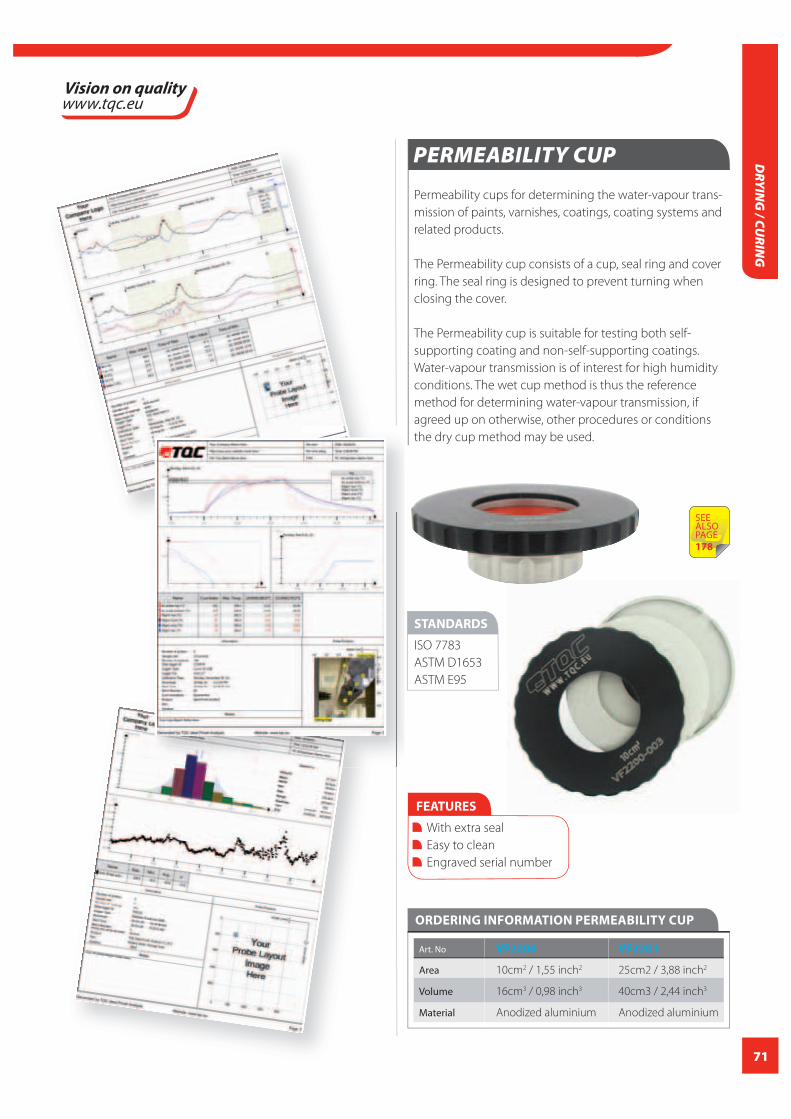
71
DRYIN
G / CU
RING
PERMEABILITY CUP
Permeability cups for determining the water-vapour trans-
mission of paints, varnishes, coatings, coating systems and
related products.
The Permeability cup consists of a cup, seal ring and cover
ring. The seal ring is designed to prevent turning when
closing the cover.
The Permeability cup is suitable for testing both self-
supporting coating and non-self-supporting coatings.
Water-vapour transmission is of interest for high humidity
conditions. The wet cup method is thus the reference
method for determining water-vapour transmission, if
agreed up on otherwise, other procedures or conditions
the dry cup method may be used.
FEATURES
With extra seal
Easy to clean
Engraved serial number
ORDERING INFORMATION PERMEABILITY CUP
Art. No VF2200 VF2201
Area 10cm2 / 1,55 inch2 25cm2 / 3,88 inch2
Volume 16cm3 / 0,98 inch3 40cm3 / 2,44 inch3
Material Anodized aluminium Anodized aluminium
STANDARDS
ISO 7783
ASTM D1653
ASTM E95
SEE ALSOPAGE178

72
HA
RDN
ESS
/ SCR
ATCH
/ EL
AST
ICIT
Y
Deformation Resistance
Physical properties of paint and coatings play an important
role in the quality control. Depending on the application
a coating is supposed to be extremely hard and rigid such
as for example the coating on the hull of an ice-breaker.
Automotive coatings however require a certain fl exibility
since the thin sheet metal of a car body is not fully rigid
and a slamming hood should not cause the paint to break.
Coil coated steel that is to be formed into products such
as white goods or cladding should have excellent forming
properties.
Several empirical tests There are a number of diff erent empirical tests that are used
to deform test panels and so assess the deformation resis-
tance or fl exibility. Coatings that fail such a test will crack
and/or detach from the substrate. Also there is quite some
overlap between diff erent test systems and their results.
Many tests provide information about similar parameters
such as elasticity / forming resistance, adhesion, hardness,
brittleness, stress resistance etc..
Although some tests overlap there is no cross-reference for
their results.
Commonly used testsCommon tests used in the paint and coatings industry are:
With this system a coated test panel or lacquered sheet
metal is bent over a defi ned mandrel. Cylindrical man-
drels in diff erent diameters or conical mandrels are used.
The smaller the diameter the sharper the forming of the
test panel which leads to elongation of the panel includ-
ing the coating. A sharper deforming causes more stress
to the coating which may lead to cracks or adhesion
failure.
Cylindrical bend test are recognised to be more precise in
comparison to conical bend tests which have the
advantage that a range of mandrel diameters can be
checked on just one panel.
With an impact test a rapid deformation of a painted
test panel is generated. A specifi ed weight with a
specifi ed punch is dropped on a test panel from diff erent
heights. The damage on the sample is observed after the
test and provides information about physical properties
of the coating such as elasticity, hardness and adhesion.
For the paint industry there are diff erent tests accord-
ing ISO 6272 , ASTM D2794 and others. Each standard
has its own specifi cs such as weight, punch shape, direct
or indirect impact etc..
HARDNESS / SCRATCH / ELASTICITY

73
HA
RDN
ESS / SCRATCH
/ ELASTICITY
Cupping testers generate, in contradiction to impact
testers, a gradual deformation of the sample. An indenter
with a specifi ed shape is slowly forced through the test
panel under standardised conditions. During the
deformation the panel is visually observed. The cupping
value of a coating is the deformation point at which the
coating starts to crack.
To perform this test correctly it is of utmost importance
that the deformation is made gradually without any
interruptions.
Scratch Resistance
The property of a substance that is resistant to repeated
rubbing or scratching. In general, it meant the resistance
of a (coating) layer or surface against mechanical friction.
Abrasion of products is a concept that can’t be handled in
general. One must explicitly specify the conditions under
which the product must be durable.
Any change in wear conditions, the assessment of the
wear thoroughly change. In general we distinguish wear as
single or repetitive. In the former case, a small contamina-
tion in the long run leads to serious damage. By repeating
is meant the resistance of a surface under prolonged load.
The lowering of the coeffi cient of friction can give a signifi -
cant improvement. For the determination of the abrasion
resistance it should be practical to approach conditions as
much as possible.
Forms of wear or scratch resistance are e.g. brush
abrasion testing, rotating abrasion testing, rub testing, sand
fall testing and or shear tests.
Hardness
The determination of the reactive resistance, the hardness
of a surface of which a coating or alternative protective
layer is provided. As with abrasion and scratch resistance
there should be an explicit reference given to the hardness
meant. Under the hardness of the coatings is in general
understood the impression value at which a deformation of
the coating occurs. This is determined by pressing sharp or
blunt stylus, depending on the material or coating, into the
surface.
Another method to measure hardness is the determination
of rolling resistance of a coated surface. The equipment
required is using spheres that fi nd resistance during the
rolling movement on the test surface i.e. Pendulum hard-
ness. The degree of hardness determines on the number of
movements by a pendulum roller experiencing resistance
during this process.
Other types of hardness tests are, Barcol Impression, Shore
A-D, Sclerometer and Wolf-Wilburn pencil scratch resistance
determination and Persoz or Konig pendulum hardness
testers.

74
HA
RDN
ESS
/ SCR
ATCH
/ EL
AST
ICIT
Y
TQC AUTOMATIC PENDULUM HARDNESS TESTER
The TQC Automatic Pendulum Hardness Tester has a lot of
unique features that ease defi ning hardness by the König
and/or Persoz method as described in ISO 1522. Both meth-
ods work on the principle that the damping time of a
pendulum oscillating on a sample indicates the hardness.
The instrument has an easy menu-driven interface with
jog dial. The automated electronic counting mechanism
is not aff ected by refl ections from the surrounding
area. The water-level is located on the test
specimen, rather than on the instrument’s base.
Once the instrument is leveled further calibration
is not required. The gas-spring supported
transparent draft cover allows easy access to all
parts of the instrument.
TQC’s Pendulum Hardness Tester is a modular system. The
instrument itself can be used for both the König and- Persoz
method. Both pendulums should be ordered separately.
After placing the correct pendulum, switching between the
two measuring methods only takes a push of a button. The
Pendulum is positioned fully automatically by means of a
stepper motor. Also the release of the Pendulum is auto-
mated through electro-magnetic system. The end of a test
is indicated by a visual and acoustic signal.
The TQC Pendulum Hardness Tester base device is
available as a 100 Volt and a 230 Volt model.
FEATURES
Suitable for both Persoz and König Tests. Switching between methods only takes a push of a button. Automatic pendulum positioning Easy menu-driven interface with jog-dial. The gas-spring supported transparent draft cover allows easy access to all parts The spirit level is located on the test specimen. Once leveled further calibration is not required. Visual and acoustic signal when test is performed.
Design ‘Solid Supports’ to level the instrument. Integrated storage of glass plate and pendulum To eliminate human errors the release of the pendulum is automated through an electro-magnetic system. Easy panel access Menu-driven calibration menu eases both Persoz- and König calibration.
TECHNICAL SPECIFICATIONS TQC PENDULUM HARDNESS TESTER
SP0500 Base Instrument
Menu language English, German, French, Spanish, Italian
Display Blue Illuminated, graphic 100x35 mm /
3,94x1,38 inch, 193x64 pixels
Thickness glass plate 6 mm / 0,24 inch
Material Stainless steel (front plate and small parts)
Powdercoated steel (housing)
Anodized aluminum (left panel)
Perspex (draft cover)
Dimensions 430x430x740 mm / 29,1x16,9x16,9 inch
(DxWxH) (closed cover)
650x430x960 mm / 37,8x16,9x25,6 inch
(open cover)
Weight 26 kg / 57,3 lbs
CCICALIBRATION
CERTIFICATION
INCLUDED
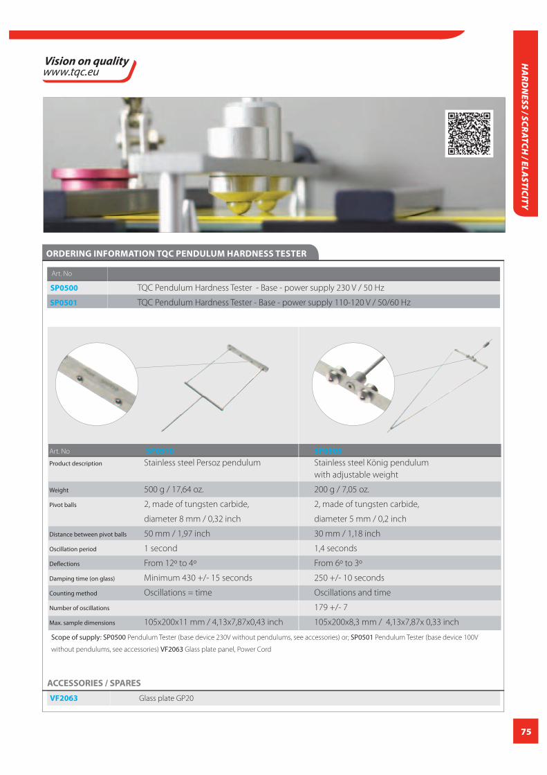
75
HA
RDN
ESS / SCRATCH
/ ELASTICITY
ACCESSORIES / SPARES
VF2063 Glass plate GP20
ORDERING INFORMATION TQC PENDULUM HARDNESS TESTER
Art. No
SP0500 TQC Pendulum Hardness Tester - Base - power supply 230 V / 50 Hz
SP0501 TQC Pendulum Hardness Tester - Base - power supply 110-120 V / 50/60 Hz
Art. No SP0510 SP0505
Product description Stainless steel Persoz pendulum Stainless steel König pendulum
with adjustable weight
Weight 500 g / 17,64 oz. 200 g / 7,05 oz.
Pivot balls 2, made of tungsten carbide, 2, made of tungsten carbide,
diameter 8 mm / 0,32 inch diameter 5 mm / 0,2 inch
Distance between pivot balls 50 mm / 1,97 inch 30 mm / 1,18 inch
Oscillation period 1 second 1,4 seconds
Defl ections From 12º to 4º From 6º to 3º
Damping time (on glass) Minimum 430 +/- 15 seconds 250 +/- 10 seconds
Counting method Oscillations = time Oscillations and time
Number of oscillations 179 +/- 7
Max. sample dimensions 105x200x11 mm / 4,13x7,87x0,43 inch 105x200x8,3 mm / 4,13x7,87x 0,33 inch
Scope of supply: SP0500 Pendulum Tester (base device 230V without pendulums, see accessories) or; SP0501 Pendulum Tester (base device 100V
without pendulums, see accessories) VF2063 Glass plate panel, Power Cord

76
HA
RDN
ESS
/ SCR
ATCH
/ EL
AST
ICIT
Y
FEATURES
Buchholz indenter is equipped with functional grips allowing gentle placing and lifting of the instrument Pins and cutting part of indenter are made of hardened steel preventing wear High quality microscope with precision glass optical lenses and strong illuminator allows a clear visibility of the, often hard to see, indentation mark Dual timer can be pre-set for both “in-position“ time and “recovering” time Separate level gauge allows checking the correct level of the test panel before the test is performed
ORDERING INFORMATION BUCHHOLZ HARDNESS INDENTATION TEST
Art. No
SP1900 Buchholz indentation test
Scope of supply: Buchholz Indentation Test, Calibrated slip-on weight
with a special cutter, Illuminated microscope with 20x magnification, Level
gauge, Digital dual timer, Two markers with template, 3 x AAA batteries
ACCESSORIES / SPARES
SP1935 Template
SP1930 Black marker
SP1931 White marker
LD6170 Surface Microscope 20X
DI0085 Digital Dual Clock Timer
TECHNICAL SPECIFICATION SBUCHHOLZ HARDNESS INDENTATION TEST
Material Stainless Steel
Weight complete apparatus 1000 +/-5 g / 35.27 +/-0,18 oz.
(load upon indentor 500 +/-5 g / 17,63 +/- 0,18 oz.)
Magnification 20 X
microscope
Dimensions 78x45x51 mm / 3,07x1,77x2,01 inch
BUCHHOLZ HARDNESS INDENTATION TEST
The TQC Buchholz Hardness Indentation Test provides a
method for carrying out an indentation test on coatings
in comliance with the ISO 2815-2003 standard. The TQC
Buchholz Hardness Indentation Test consists of a calibrated
slip-on weight with a sharp-edged metal wheel, an
illuminated microscope, a level gauge, a digital dual timer,
and two markers with template.
The calibrated slip-on weight with specified-
edged metal wheel is positioned on the test
specimen for a set period of time. The length
of the indentation mark in the coating is an
indication of the hardness of the surface.
The Buchholz Hardness Indentation Test is
a mandatory test in Qualicoat, QIB and GSB
accredited laboratories.
STANDARDS
ISO 2815
BS 30900 E 9
ECCA T12
NF T30-052
CCICALIBRATION
CERTIFICATION
INCLUDED
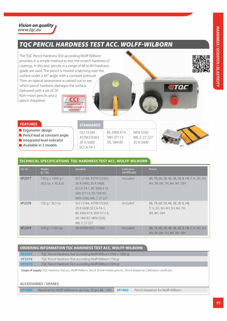
77
HA
RDN
ESS / SCRATCH
/ ELASTICITY
TQC PENCIL HARDNESS TEST ACC. WOLFF-WILBORN
The TQC Pencil Hardness Test according Wolff Wilborn
provides in a simple method to test the scratch hardness of
coatings. In this test, pencils in a range of 6B to 8H hardness-
grade are used. The pencil is moved scratching over the
surface under a 45° angle with a constant pressure.
Then an optical assessment is carried out to see
which pencil hardness damages the surface.
Delivered with a set of 20
Koh-i-noor pencils and a
pencil sharpener.
FEATURES
Ergonomic design Pencil lead at constant angle Integrated level indicator Available in 3 models
STANDARDS
ISO 15184
ASTM D3363
JIS K-5600
ECCA-T4-1
BS 3900-E19
SNV 37113
SIS 184187
NEN 5350
MIL C 27 227
JIS K-5400
TECHNICAL SPECIFICATIONS TQC HARDNESS TEST ACC. WOLFF-WILBORN
Art. No Weight Standard Calibration Pencils g / oz. certificate
VF2377 750 g + 1000 g / ISO 15184, ASTM D3363, Included 8B, 7B, 6B, 5B, 4B, 3B, 2B, B, HB, F, H, 2H, 3H,
26,5 oz. + 35,3 oz. JIS K-5400, JIS K-5600, 4H, 5H, 6H, 7H, 8H, 9H, 10H
ECCA-T4-1, BS 3900-E19,
SNV 37113, SIS 184187,
NEN 5350, MIL C 27 227
VF2378 750 g / 26,5 oz. ISO 15184, ASTM D3363, Included 8B, 7B, 6B, 5B, 4B, 3B, 2B, B, HB,
JIS K-5600, ECCA-T4-1, F, H, 2H, 3H, 4H, 5H, 6H, 7H,
BS 3900-E19, SNV 37113, 8H, 9H, 10H
SIS 184187, NEN 5350,
MIL C 27 227
VF2379 500 g / 17,64 oz. JIS-K5600 (ISO 15184) Included 8B, 7B, 6B, 5B, 4B, 3B, 2B, B, HB, F, H, 2H, 3H,
4H, 5H, 6H, 7H, 8H, 9H, 10H
ACCESSORIES / SPARES
VF1000 Pencil set for Wolff-Wilborn in alu box, 20 pcs 8B - 10H. VF1003 Pencil sharpener for Wolff-Wilborn
ORDERING INFORMATION TQC HARDNESS TEST ACC. WOLFF-WILBORN
VF2377 TQC Pencil Hardness Test according Wolff Wilborn (750 + 1000 g)
VF2378 TQC Pencil Hardness Test according Wolff Wilborn (750 g)
VF2379 TQC Pencil Hardness Test according Wolff Wilborn (500 g)
Scope of supply: TQC Hardness Test acc. Wolff-Wilborn, Set of 20 Koh-I-Noor pencils , Pencil sharpener, Calibration certificate
CCICALIBRATION
CERTIFICATION
INCLUDED

78
HA
RDN
ESS
/ SCR
ATCH
/ EL
AST
ICIT
Y
HARDNESS PEN
The TQC Hardness Pen is a pocket instrument for testing
the hardness and wear/scratch resistance of materials such
as coatings, lacquers, plastics or related products. A tung-
sten carbide tip is drawn over the surface with a defined
constant pressure. The pressure on the tip can be changed
using the slide or by changing the spring. A visual mark on
the surface after use of the TQC Hardness Pen indicates a fail
of the surface hardness or wear/scratch resistance. Can be
used on flat and curved surfaces.
The laser-engraved scale is clearly visible on the grey back-
ground. The diameter of the tips are Ø1 mm, Ø 0.75 mm
(Bosch) and Ø 0.5 mm (van Laar).
The TQC Hardness pen is available in 2 models, the Basic
and Pro version. The pro version is supplied with a pen
holder guided by two ball bearings and includes all 3 tips.
The Basic version is only supplied with the 1mm tip and
without pen holder.
FEATURES
Ergonomic design with anti-slip texture on the holding point Made of maintenance-free anodized aluminium, tips in tungsten carbide
Range 0-3 N, 0-10 N and 0-30 N
Material Anodized aluminium enclosure
Probe made of tungsten carbide
Dimensions Ø 14 to 19 mm, length 175 mm / Ø 0,55 to 0,75
inch, length 6,89 inch
Weight 60 g / 2,12 oz.
TECHNICAL SPECIFICATIONS HARDNESS PEN
ORDERING INFORMATION HARDNESS PEN
Art. No
SP0010 TQC Hardness Test Basic
SP0015 TQC Hardness Test Pro
ACCESSORIES / SPARES
SP0012 Tip for hardness test Diameter 0.5 mm / R=0.25 (acc. to Opel, Volvo, van Laar)
SP0013 Tip for hardness test Diameter 0.75 mm / R=0.375 (acc. to Bosch, Volvo)
SP0014 Tip for hardness test Diameter 1mm/ R=0,5
Scope of supply SP0010: TQC Hardness pen, 3 springs, 1 mm tip, sturdy case
Scope of supply SP0015: TQC Hardness pen, 3 springs, 1 mm tip, 0.5 mm tip, 0,75 mm tip, pen holder
with guidance wheels, sturdy case
SP0015
STANDARDS
ISO 1518
AS 3894.4
EN 438-2
SIS 184188
CORPORATED STANDARDS:
SP0010

79
HA
RDN
ESS / SCRATCH
/ ELASTICITY
SHORE HARDNESS GAUGE DIN 53505 ISO 868 ASTM D2240
The TQC Shore Hardness Gauge is a reliable instrument
for measuring the impression hardness of soft materials
such as coatings, plastics and rubber. Equipped with a drag
indicator, which holds the highest measured value. Delivery
includes a simple test block.
STANDARDS
ISO 868
ASTM D2240
DIN 53505
FEATURES
Made of anodized aluminum and stainless steel Easy to use Versatile, applicable for variety of materials Drag pointer gives the maximum reading of the hardness Revolving graduation scale Test Block included
TECHNICAL SPECIFICATIONS SHORE HARDNESS GAUGE DIN 53505 ISO 868 ASTM D2240
Art. No LD0550 LD0551
Type Shore A Shore D
Application elastomers, vinyl, rubber, leather, pvc, polyester, ABS, nylon, polyurethane, kevlar,
silicone, teflon, neopreen, etc.. acryl, wood, polystyrene etc..
Test Block 25, 50, 75 shore hardness 10 shore hardness
Range 0-100 0-100
Accuracy 0,006 0,006
Material Stainless steel, anodized aluminium Stainless steel, anodized aluminium
Dimensions 25x110x60 mm / 0,98x4,33x2,36 inch 25x110x60 mm / 0,98x4,33x2,36 inch
Weight 230 g / 8,11 oz 230 g / 8,11 oz
ORDERING INFORMATION SHORE HARDNESS GAUGE DIN 53505 ISO 868 ASTM D2240
Art. No Art. No
LD0550 Shore hardness gauge - Shore A LD0551 Shore hardness gauge - Shore D
DIN 53505 ISO 868 ASTM D2240 DIN 53505 ISO 868 ASTM D2240
Scope of supply: Hardtop box, Durometer, Manual, testblock
Art. No
ACCESSORIES / SPARES
LD0559* Durometer Test Stand
LD0554 Weight 4000g Shore D for TQC Stand
LD0555 TQC Shore Hardness Testblock Kit, 7 test blocks for Durometer A
LD0556 TQC Shore Hardness Testblock Kit, 3 test blocks for Durometer D
*When test stand is used with the shore D the weight of 4000gr (LD0554) is necessary

80
HA
RDN
ESS
/ SCR
ATCH
/ EL
AST
ICIT
Y
SHORE HARDNESS TESTBLOCK KIT
Shore Hardness Testblock Kit with different values of hard-
ness. As a reference check it will indicate if a
durometer is operating within tolerances. The indivual test
blocks are provided with serial numbers to guarantee
incontestable identification. Comes with custom made
carrying case.
STANDARDS
ISO 868
ASTM D2240
DIN 53505
FEATURES
Supplied with certificate
Every block provided with unique serial number
TECHNICAL SPECIFICATIONS SHORE HARDNESS TESTBLOCK KIT
LD0555 TQC Shore Hardness Testblock Kit,
7 test blocks for Durometer A
Range 30, 40, 50, 60, 70, 80 and 90 shore
hardness
Dimensions 54 mm x 54 mm x 8 mm /
2,13 x 2,13 x 0,32 inch
Calibration Certificate included
LD0556 TQC Shore Hardness Testblock Kit,
3 test blocks for Durometer D
Range 60, 75, and 85 shore hardness
Dimensions 51 mm x 51 mm x 9,5 mm /
2,01 x 2,01 x 0,37 inch
Calibration Certificate included
ORDERING INFORMATION SHORE HARDNESS TESTBLOCK KIT
Art. No
LD0555 Shore hardness testblock kit (for Durometer A)
LD0556 Shore hardness testblock kit (for Durometer D)
Scope of supply: Test Block, Calibration Certificate, Custom made
carrying case
CCICALIBRATION
CERTIFICATION
INCLUDED
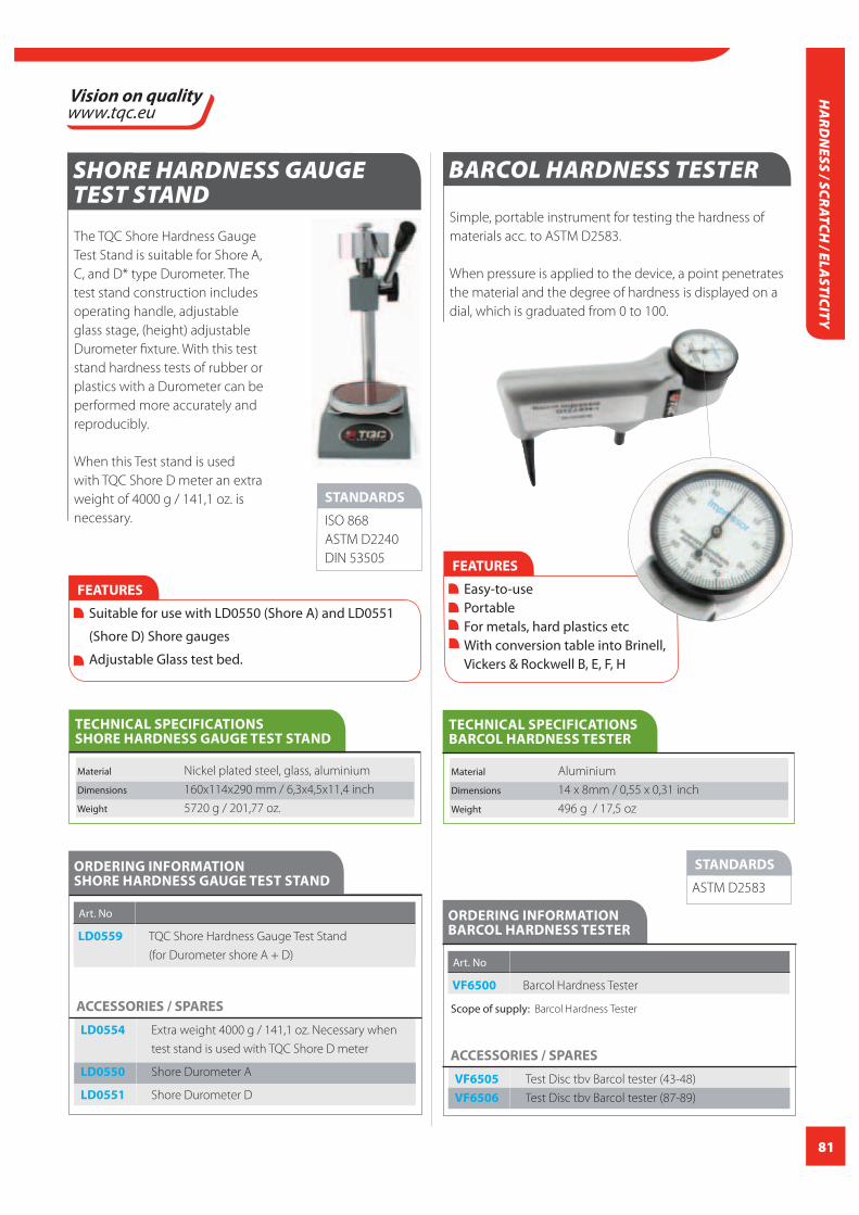
81
HA
RDN
ESS / SCRATCH
/ ELASTICITY
STANDARDS
ISO 868
ASTM D2240
DIN 53505
FEATURES
Suitable for use with LD0550 (Shore A) and LD0551
(Shore D) Shore gauges
Adjustable Glass test bed.
TECHNICAL SPECIFICATIONS SHORE HARDNESS GAUGE TEST STAND
Material Nickel plated steel, glass, aluminium
Dimensions 160x114x290 mm / 6,3x4,5x11,4 inch
Weight 5720 g / 201,77 oz.
The TQC Shore Hardness Gauge
Test Stand is suitable for Shore A,
C, and D* type Durometer. The
test stand construction includes
operating handle, adjustable
glass stage, (height) adjustable
Durometer fixture. With this test
stand hardness tests of rubber or
plastics with a Durometer can be
performed more accurately and
reproducibly.
When this Test stand is used
with TQC Shore D meter an extra
weight of 4000 g / 141,1 oz. is
necessary.
SHORE HARDNESS GAUGE TEST STAND
ORDERING INFORMATION SHORE HARDNESS GAUGE TEST STAND
Art. No
LD0559 TQC Shore Hardness Gauge Test Stand
(for Durometer shore A + D)
ACCESSORIES / SPARES
LD0554 Extra weight 4000 g / 141,1 oz. Necessary when
test stand is used with TQC Shore D meter
LD0550 Shore Durometer A
LD0551 Shore Durometer D
BARCOL HARDNESS TESTER
Simple, portable instrument for testing the hardness of
materials acc. to ASTM D2583.
When pressure is applied to the device, a point penetrates
the material and the degree of hardness is displayed on a
dial, which is graduated from 0 to 100.
FEATURES
Easy-to-use Portable For metals, hard plastics etc With conversion table into Brinell, Vickers & Rockwell B, E, F, H
STANDARDS
ASTM D2583
TECHNICAL SPECIFICATIONS BARCOL HARDNESS TESTER
Material Aluminium
Dimensions 14 x 8mm / 0,55 x 0,31 inch
Weight 496 g / 17,5 oz
ORDERING INFORMATION BARCOL HARDNESS TESTER
Art. No
VF6500 Barcol Hardness Tester
Scope of supply: Barcol Hardness Tester
ACCESSORIES / SPARES
VF6505 Test Disc tbv Barcol tester (43-48)
VF6506 Test Disc tbv Barcol tester (87-89)

82
HA
RDN
ESS
/ SCR
ATCH
/ EL
AST
ICIT
Y
TQC CYLINDRICAL BEND TEST 100 MM / 3,94 INCH INCL MANDREL SET
The TQC Cylindrical Bend Test is used to determine the
elasticity adhesion and elongation of paint on sheet metal
in accordance with ISO 1519. A test panel (max. size
150x100 mm / 5,91x3,94 inch) is bent over a cylindrical
mandrel. The smaller the diameter of the mandrel, the larger
the tension on the coating. The test panel is then checked
for cracks or damage in the coating. The luxurious desktop
holder with 14 mandrels can also be wall mounted.
Mandatory test in Qualicoat, QIB and GSB accredited
laboratories
FEATURES
Sturdy apparatus made of a combination of anodized aluminium and stainless steel. Ergonomic clamping device for test panels and large knob on bending arm easy and smooth bending. Large test panel size: max. 150x100 mm / 5,90x3,94 inch Luxurious wall mounted / desktop mandrel holder
STANDARDS
ISO 1519
ASTM D522
TECHNICAL SPECIFICATIONS TQC CYLINDRICAL BEND TEST 100 MM / 3,94 INCH INCL MANDREL SET
Art. No SP1820 SP1822
Metric Imperial
Mandrels 14 7
Mandrel size 2, 3, 4, 5, 6, 8, 10, 12, 13, 16, 19, 20, 25 and 32 mm 1/8, 1/4, 3/8, 1/2, 5/8, 3,4, 1 inch
Min. testpanel size 105 mm on a 2 mm mandrel (4,1 inch on a 1/8 inch mandrel)
120 mm on a 32 mm mandrel (4,7 inch on a 1 inch mandrel)
Max. testpanel size 150 mm on a 2 mm mandrel (5,90 inch on a 1/8 inch mandrel)
190 mm on a 32 mm mandrel (7,4 inch on a 1 inch mandrel)
Max. testpanel thickness 1 mm 0,04 inch
Material aluminium, stainless steel aluminium, stainless steel
Weight 4150 g 146,39 oz.
Dimensions 140x170x340 mm 5,51x6,69x13,39 inch
Mandrel Holder 100x130x160 mm 3,94x5,12x6,3 inch
ORDERING INFORMATION TQC CYLINDRICAL BEND TEST 100 MM / 3,94 INCH INCL MANDREL SET
SP1820 TQC Cylindrical bend test - Metric
SP1822 TQC Cylindrical bend test - Imperial
Scope of supply: TQC Cylindrical Bend Test 100 mm / 3,94 inch, Holder with set of mandrels
Art. No
ACCESSORIES / SPARES
TQC Panels are available in a large variety of dimensions, materials and thicknesses. Use of TQC Test panels enhances reproducibility of
physical and chemical tests. Each panel is equipped with a hole for hanging and handling.
Both standard test panels and special dimensions to customers specifications are available.
SP1835 Mandrel set (14 pcs) metric
SP1833 Mandrel set (7 pcs) imperial

83
HA
RDN
ESS / SCRATCH
/ ELASTICITY
SP1831
CONICAL BEND TEST
The TQC Bend Test Conical Mandrel is a laboratory appa-
ratus to bend coated test panels over a conical shaped
mandrel in order to assess the elasticity or resistance of a
coating-, paint or varnish to cracking, elongation and/or
detachment from a metal test panel in accordance with ISO
6860 and ASTM D522. The conical shap of the bending area
allows the deformation of the test panel and examination of
the elasticity range of a coating over any diameter between
3.1 and 38 mm / 0,12 to 1,50 inch in one single test.
The TQC Bend Test Conical Mandrel is available in two types,
the Pro and Basic. The Basic edition is a simplifi ed version
of the TQC Conical Bend Test “Pro”. The sample panel of the
Pro is secured to the apparatus by means of a quick lever
handle that lock and unlocks the panel in a split second
using just hand. The sample panel of the Basic is secured by
means of two clamping knobs which has to be tightened
and untightened by turning respectively clockwise or anti-
clockwise.
FEATURES
Sturdy apparatus made of a combination of anodized aluminium and stainless steel Large knob on bending arm for easy and smooth bending Quick lock panel clamp (SP1830 only)
STANDARDS
ISO 6860
ASTM D522
TECHNICAL SPECIFICATIONS CONICAL BEND TEST
SP1830 - Pro SP1831- Basic
Material Aluminium and Stainless Steel Aluminium and Stainless Steel
Mandrel range 3,1 to 38 mm / 0,12 to 1,50 inch 3,1 to 38 mm / 0,12 to 1,50 inch
Test panel size 100x180 mm / 3,94x7,09 inch 100x180 mm /3,94x7,09 inch
Max. panel thickness 0,8 mm / 0,03 inch 0,8 mm / 0,03 inch
Sample panel securement quick lever handle Two clamping knobs (turn to (un)tighten
Apparatus dimensions 110x250x150 mm / 4,33x9,84x5,91 inch 110x270x100 mm / 4,33x10,63x3,94 inch
Weight 4200 g / 148,15 oz. 3300 g / 116,4 oz.
ORDERING INFORMATION CONICAL BEND TEST
SP1830 Conical bend test - Pro SP1831 Conical bend test - Basic
Scope of supply: Conical Bend Test Pro or Basic
SP1830

84
HA
RDN
ESS
/ SCR
ATCH
/ EL
AST
ICIT
Y
TQC AUTOMATIC CUPPING TESTER
TQC Automatic cupping tester to perform a cupping
(Erichsen / Dent) test on coated steel panels to defi ne the
resistance of paint, varnish or related products to cracking
and/or detachment from a metal substrate when subjected
to gradual deformation by indentation under standard
conditions.
The test is either used as a “pass / fail” test by testing to a
specifi ed depth or defi ning the minimum depth at which a
coating fails by gradually increasing the indentation.
The ISO1520 standard requires panels to be slowly de-
formed at a steady rate between 0,1 mm/s and 0,3 mm/s
without interruption. Especially with thicker steel
panels hand-operated testers not always allow
an uninterrupted deformation.
The TQC Automatic cupping tester is driven by
a micro-step controlled electro motor which
allows precise and steady deformation with 0,01
mm steps. Operation is intuitive by means of
a jog-dial switch and a multi-lingual operating
menu on a large illuminated display.
An integrated LED powered sample illumination system
comforts examining the coating under test. To guarantee
maximum visibility of all possible types of surface including
high gloss, matte or coloured samples the angle of the LED
light can be set. Choose light from just one or all directions.
The strength of the LED’s is adjustable but also the colours
can be changed to achieve maximum contrast.
Mandatory test in Qualicoat and QIB accredited laboratories.
STANDARDS
ISO 1520
DIN 1520
DIN 53156
DIN 53232
BS 3900-E4
NBN T22-104
NFT 30 019
FEATURES
Easy-to-use Motor driven punch Adjustable instrument orientation to ensure an ergonomic work position Manual- or preset deformation Flexible LED sample illumination. Set direction, intensity and color. Automatic zero-point calibration Acoustic and visual alarms Optional USB microscope with automatic focusing bracket Multiple languages
CCICALIBRATION
CERTIFICATION
INCLUDED

85
HA
RDN
ESS / SCRATCH
/ ELASTICITY
ORDERING INFORMATION TQC AUTOMATIC CUPPING TESTER
Art. No
SP4300 TQC Automatic Cupping Test 230V/50Hz
SP4305 TQC Automatic Cupping Test 110V/50/60Hz
Scope of supply: Automatic cupping test, reference panel, optical tool
support rod, optical tool mount, power cord, manual
TECHNICAL SPECIFICATIONS TQC AUTOMATIC CUPPING TESTER
Art. No SP4300 SP4305
Indenter Speed 0,01 – 0,70 mm/s 0,0004 - 0,028 inch/s
Stroke length 0 - 12 mm 0 - 0,47 inch
Max. panel width max. 100 mm max. 3,94 inch
Max. panel thickness steel max. 0,8 mm max. 0,03 inch
Max. panel thickness aluminium max. 1,2 mm max. 0,05 inch
Safety Emergency Button, integrated Acoustic Alarm Emergency Button, integrated Acoustic Alarm
Function Jog Shuttle knob by Jog Shuttle knob by
Rotation / Pushing Rotation / Pushing
Material Powder coated sheet metal, Powder coated sheet metal,
stainless steel, aluminium stainless steel, aluminium
Indenter Speed accuracy +/- 1% of set speed +/- 1% of set speed
Stroke length accuracy +/- 0.01 mm 0,0004 inch
Menu languages English, German, French, Italian and Spanish English, German, French, Italian and Spanish
Power Supply 230V | 50 Hz 110 – 120 V | 50/60 Hz
Power consumption max. 80 Watt max. 80 Watt
Display Blue Illuminated, graphic Blue Illuminated, graphic
100 x 35 mm, 193 x 64 pixels 3,94 x 1,38 inch, 193 x 64 pixels
Dimensions 450 x 350 x 600 mm 17,72 x 13,78 x 23,62 inch
Net weight 31 kg 68,5 lbs
Art. No
SP4330 Reference panel for TQC Auto Cupping Test 100mm
SP4331 Reference panel for TQC Auto Cupping Test 105mm
Scope of supply: Automatic cupping test, reference panel, optical tool
support rod, optical tool mount, power cord, manual
ACCESSORIES / SPARES
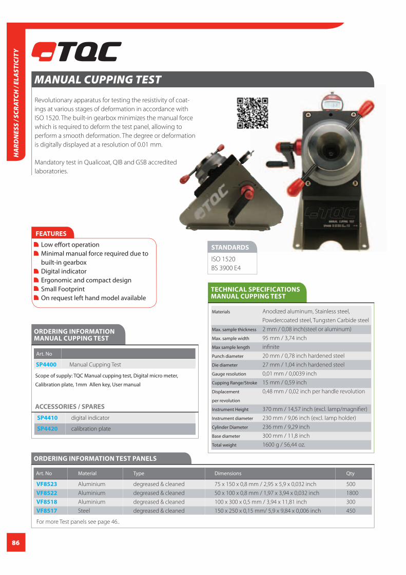
86
HA
RDN
ESS
/ SCR
ATCH
/ EL
AST
ICIT
Y
MANUAL CUPPING TEST
Revolutionary apparatus for testing the resistivity of coat-
ings at various stages of deformation in accordance with
ISO 1520. The built-in gearbox minimizes the manual force
which is required to deform the test panel, allowing to
perform a smooth deformation. The degree or deformation
is digitally displayed at a resolution of 0.01 mm.
Mandatory test in Qualicoat, QIB and GSB accredited
laboratories.
STANDARDS
ISO 1520
BS 3900 E4
FEATURES
Low eff ort operation Minimal manual force required due to built-in gearbox Digital indicator Ergonomic and compact design Small Footprint On request left hand model available
TECHNICAL SPECIFICATIONS MANUAL CUPPING TEST
Materials Anodized aluminum, Stainless steel,
Powdercoated steel, Tungsten Carbide steel
Max. sample thickness 2 mm / 0,08 inch(steel or aluminum)
Max. sample width 95 mm / 3,74 inch
Max sample length infi nite
Punch diameter 20 mm / 0,78 inch hardened steel
Die diameter 27 mm / 1,04 inch hardened steel
Gauge resolution 0,01 mm / 0,0039 inch
Cupping Range/Stroke 15 mm / 0,59 inch
Displacement 0,48 mm / 0,02 inch per handle revolution
per revolution
Instrument Height 370 mm / 14,57 inch (excl. lamp/magnifi er)
Instrument diameter 230 mm / 9,06 inch (excl. lamp holder)
Cylinder Diameter 236 mm / 9,29 inch
Base diameter 300 mm / 11,8 inch
Total weight 1600 g / 56,44 oz.
ORDERING INFORMATION MANUAL CUPPING TEST
Art. No
SP4400 Manual Cupping Test
Scope of supply: TQC Manual cupping test, Digital micro meter,
Calibration plate, 1mm Allen key, User manual
ACCESSORIES / SPARES
SP4410 digital indicator
SP4420 calibration plate
ORDERING INFORMATION TEST PANELS
Art. No Material Type Dimensions Qty
VF8523 Aluminium degreased & cleaned 75 x 150 x 0,8 mm / 2,95 x 5,9 x 0,032 inch 500
VF8522 Aluminium degreased & cleaned 50 x 100 x 0,8 mm / 1,97 x 3,94 x 0,032 inch 1800
VF8518 Aluminium degreased & cleaned 100 x 300 x 0,5 mm / 3,94 x 11,81 inch 300
VF8517 Steel degreased & cleaned 150 x 250 x 0,15 mm/ 5,9 x 9,84 x 0,006 inch 450
For more Test panels see page 46..

87
HA
RDN
ESS / SCRATCH
/ ELASTICITY
IMPACT TEST
The TQC Impact Test is used to
determine the impact resistivity
and fl exibility of coatings. The three
scale instrument is equipped with
a special guidance which assures
that the distance between each
impact is always according to the
standard. For correct position-
ing a spirit-level is built-in. Each
Impact test comes as a complete
set (instrument and accessoires) to
perform a test.
Mandatory test in Qualicoat, QIB
and GSB accredited laboratories.
FEATURES
The triple scale instrument is equipped with a special guidance which assures that the distance between each impact is always according to the standard. For correct positioning a spirit-level is built-in.
STANDARDS
DIN-EN-ISO 6272
ASTM D2794
ASTM G14
TECHNICAL SPECIFICATIONS IMPACT TEST
SP1880 SP1890 SP1891 SP1895
with bubble level
release punch
vise with spring clamp
20 mm
ORDERING INFORMATION IMPACT TEST
Art. No
SP1880 TQC Impact Test according to ISO 6272-2 and ASTM D2794, Type: Indirect Impact Tester, Content: Base plate assembly,
guide tube, release collar, punch Ø12.7 mm / 0.5 inch , punch Ø15.9 mm / 0.625 inch,
weight 1 kg, die Ø16.3 mm / 0.63 inch
SP1895 TQC Impact Test according to ASTM G14, Type: Direct Impact Tester, Content: Base plate assembly, guide tube, release
collar, punch Ø15.9 mm / 0.625 inch weight 1.361 kg and a V-notch vise with spring clamp to hold the pipe
SP1890 TQC Impact Test according to ISO 6272-1, Type: Direct Impact Tester, Content: Base plate assembly, guide tube, release
collar, clamp device, ball Ø20 mm, die 27mm, weight 1 kg / 2.2 lbs
SP1891 TQC Impact Test according to ISO 6272-1 and ASTM D2794 (before 1993), Type: Direct Impact Tester,
Content: Base plate assembly, guide tube, release collar, clamp device, ball Ø20 mm, die 27mm, weight 1 kg / 2.2 lbs,
ball Ø15.9 mm / 0.62 inch, die 16.3mm / 0.63 inch, weight 0.9 kg / 2 lbs
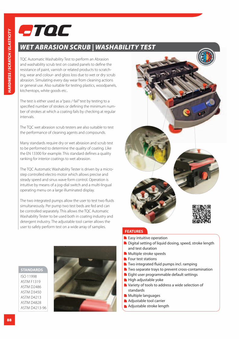
88
HA
RDN
ESS
/ SCR
ATCH
/ EL
AST
ICIT
Y
WET ABRASION SCRUB | WASHABILITY TEST
TQC Automatic Washability Test to perform an Abrasion
and washability scrub test on coated panels to defi ne the
resistance of paint, varnish or related products to scratch-
ing, wear and colour- and gloss loss due to wet or dry scrub
abrasion. Simulating every day wear from cleaning actions
or general use. Also suitable for testing plastics, woodpanels,
kitchentops, white goods etc..
The test is either used as a “pass / fail” test by testing to a
specifi ed number of strokes or defi ning the minimum num-
ber of strokes at which a coating fails by checking at regular
intervals.
The TQC wet abrasion scrub testers are also suitable to test
the performance of cleaning agents and compounds.
Many standards require dry or wet abrasion and scrub test
to be performed to determine the quality of coating. Like
the EN 13300 for example. This standard defi nes a quality
ranking for interior coatings to wet abrasion.
The TQC Automatic Washability Tester is driven by a micro-
step controlled electro motor which allows precise and
steady speed and sinus wave form control. Operation is
intuitive by means of a jog-dial switch and a multi-lingual
operating menu on a large illuminated display.
The two integrated pumps allow the user to test two fl uids
simultaneously. Per pump two test beds are fed and can
be controlled separately. This allows the TQC Automatic
Washability Tester to be used both in coating industry and
detergent industry. The adjustable tool carrier allows the
user to safely perform test on a wide array of samples.
STANDARDS
ISO 11998
ASTM F1319
ASTM D2486
ASTM D3450
ASTM D4213
ASTM D4828
ASTM D4213-96
FEATURES
Easy intuitive operation Digital setting of liquid dosing, speed, stroke length and test duration Multiple stroke speeds Four test stations Two integrated fl uid pumps incl. ramping Two separate trays to prevent cross-contamination Eight user programmable default settings High adjustable yoke Variety of tools to address a wide selection of standards Multiple languages Adjustable tool carrier Adjustable stroke length

89
HA
RDN
ESS / SCRATCH
/ ELASTICITY
TECHNICAL SPECIFICATIONS WET ABRASION SCRUB | WASHABILITY TEST
Basic Unit
Power Supply 110-120 V | 50/60 Hz
230 V| 50 Hz
Power consumption max. 80 Watt
Display Blue Illuminated, graphic 100x35 mm /
0,22x0,08 inch, 193x64 pixels
Safety Emergency Button, integrated Acoustic
Alarm
Function Jog Shuttle knob by Rotation / Pushing
Indenter Speed accuracy +/- 1% of set speed
Pump Speed accuracy +/- 1% of set speed
Stroke length accuracy +/- 0.01 mm / 4 mil
Stroke speed 1 – 60 strokes / minute*
Stroke length 20 - 300 mm / 0,8 - 11,8 inch*
Max. panel width max. 80 mm per channel
Max. panel length max. 350 mm / 3,15 inch
Max. panel thickness max. 35 mm / 1,4 inch in the
middle of the sample track
Stroke speed and depend on the tools used.
Length achievable
Dimensions 350x350x650 mm /
25,6x13,8x13,8 inch
Net weight approx. 3,5 kg / 7,72 lbs
ORDERING INFORMATION WET ABRASION SCRUB | WASHABILITY TEST
Art. No AB5000 AB5005
Power Supply 230 V | 50 Hz 110-120 V | 50/60 Hz
Scope of supply: Automatic washability test, Two test beds, Two sample clamps, Tubing and fluid container set, Power cord, Manual
Art. No
ACCESSORIES / SPARES
Art. No Standard Description
AB5010 DIN 53778 Wild Boar Brush, with Weight 60g / 0.13 lbs
AB5011 ASTM D2486 Nylon Brush, with Weight 60g / 0.13 lbs and Weight 100g / 0.22 lbs
AB5012 ASTM D4213-92 / D4828 Sponge with Weight 60g / 0.13 lbs and Weight 100g / 0.22 lbs
AB5013 ISO 11998 Abrasive pad (without weights)
AB5020 - Universal material clamp tool
AB5014 - Weight 60g / 0.13 lbs
AB5015 - Weight 100g / 0.22 lbs
AB5016 - Set of 5 spare abrasives for Tool AB5013
AB5017 - Spare wild boar brush for tool AB5010
AB5018 - Spare Nylon brush for tool AB5011
AB5019 - Set of 5 spare sponges for Tool AB5012
AB5025 ASTM D2486 Metal Shims for ASTM D2486 small (set of 4)
AB5027 ASTM D2486 Metal Shims for ASTM D2486 large (set of 4)
AB5010 AB5011
AB5012 AB5013

90
HA
RDN
ESS
/ SCR
ATCH
/ EL
AST
ICIT
Y
SHEAR SCRATCH TESTER - TABER
Motorised instrument for testing the resistance to scratch-
ing of materials. A sample plate rotates while a conical
diamond point is pressed on the sample plate. The relation
between the depth of the scratch and the applied (pre-set)
pressure indicates the hardness.
FEATURES
Constant speed motor Balanced, calibrated scale beam Variable load from 0 - 1000 g / 0 - 35,27 oz. Adjustable gage block tests up to 12,5 mm / 0,5 inch thick specimens Soft touch ON/OFF switch Interchangeable tools
ORDERING INFORMATIONTABER SHEAR SCRATCH TESTER
Art. No
TB2000 Taber 551 Shear/Scratch Tester–5 rpm (230V,50Hz)
Scope of supply: 500 g / 17,6 oz. Calibrated Weight (2 each), S-20 Precision Ground Tungsten Carbide Tool, Conical Diamond Tool, 10 x Measuring
Magnifier, Spirit Bubble Level, Hex Wrench
ACCESSORIES / SPARES
Contour Shear Tool (Honda and Toyota requirements), Diamond Scratch Tool (converging point 3 sides of cube), Scratch Tip,
1,0 mm / 0,039 inch diameter hemisphere, Diamond Standardization Plates, Scale Beam Height Extension Kit, 15N Scale Beam
Fixed Weight
TECHNICAL SPECIFICATIONSTABER SHEAR SCRATCH TESTER
Material Aluminium, Stainless Steel
Weight 13 kg

91
HA
RDN
ESS / SCRATCH
/ ELASTICITY
ABRASER - TABER
Taber Abrasion is used to determine relative resistance to
abrasion defined as ‘the ability of a material to withstand
mechanical damage’ such as rubbing, scraping or erosion.
The Taber Abraser is an industry standard used in the wear
and durability testing of parquet, metals, leather, textiles,
rubber, lacquered surfaces, carpets, coatings etc..
Single or dual versions available. A wide range of accessories
and options is available.
Complies with virtually all relevant international standards
such as Normen.
FEATURES
Platform speeds 60 and 72 rpm Quick Release Wheel Hub Balanced, calibrated arms and wheel mounts Vacuum system with precision height adjustment Rugged aluminium housing Membrane control panel with digital display Precision stainless steel weights Accessory electrical receptacle
TECHNICAL SPECIFICATIONS TABER ABRASER
Material Aluminium, Stainless Steel
ORDERING INFORMATION TABER ABRASER
Art. No TB0156 TB0157
Taber 5135 Single Head Abraser Set Taber 5155 Dual Head Abraser Set
Scope of supply: Taber Abraser, Auxiliary weights 500 g load and 1000 g load, Specimen holder (E100-125), Hold down ring (E-100-101)
Refacing Discs (S-11), Specimen mounting card sample package (S-36), Calibrade Abrading wheel set (CS-10), Calibrade Abrading wheel set (H-18)
ACCESSORIES / SPARES
Calibration / Verification kit, Sample cutter, Wheel refacer, Quiet cabinet, Grit feeder, Scuffing head attachment, Multi-media attachment
Interchangeable specimen tables, Arm height extension kit, Selection of abrading wheel sets, Test accessories, Haze kit
STANDARDS
EN 438-2
EN 660-2
EN 13329:E
EN 13672
EN 13696
EN 14431
EN 14864
EN-ISO 5470-1
ASTM D1044
ASTM D3389
ASTM D3730
ASTM D3884
ASTM D4060
ASTM D4685
ASTM D4712
ASTM D5146
ASTM D5324
ASTM D6037
ASTM D7255
ASTM F362
ASTM F510
ASTM F1478
BS 3900
DIN 52347
DIN 53109
DIN 53754
DIN 53799
DIN 68861 T2
ISO 7784-2
ISO 9352
TAPPI T476
NEN 1857

92
HA
RDN
ESS
/ SCR
ATCH
/ EL
AST
ICIT
Y
LINEAR ABRASER - TABER
The TABER® Linear Abraser is designed to test virtually any
size or shape specimen, the Linear Abraser is ideal for mate-
rial properties of contoured surfaces and finished products.
Initially developed to evaluate wear resistance, this instru-
ment can also be used to evaluate scratch resistance (single
or multiple pass), color transfer (commonly referred to as
crocking or a crockmeter), and perform coin scrape tests.
Plus, with the universal or a custom attachment, ‘real world’
testing and other forms of material durability can be per-
formed. The Linear Abraser can be used for both wet and
dry testing.
FEATURES
Eleven stroke lengths ( 5 to 100 mm / 0,2 to 4,0 inch) Variable stroke speed from 2 - 75 cycles per minute Preset stroke speed buttons for 2, 15, 25, 30, 40, 60 cycles per minute Variable load from 350 - 2100 g / 12,35 - 74,1 oz. with optional weight discs Stainless Steel Wearaser Collet for use with virtified or resilient Wearsers Laser alignment guide Programmable up to 999,999 cycles 115 V / 230 V switchable
ORDERING INFORMATION TABER LINEAR ABRASER
Art. No
TB0165 Taber 5750 Linear wear resistance tester
Scope of supply: Wearaser collet and spline shaft (350 g / 12,35 oz.), 250 g / 8,82 oz. weight discs (3 ea.), CS-10 wearasers (pkg. 10), H-18 wearasers (pkg. 5)
Power cords (115 V & 230 V), Hex L-key tool, Wearaser depth gauge tool, S-14 refacing strips (pkg. 50), Hand brush
ACCESSORIES / SPARES
Wide selection of abradants:, Calibrase CS-8, CS-10F, CS-10, CS-17, Calibrade H-10, H-18, H-22, H-38, T-slot universal table, Auxiliary
weight discs (10, 20, 50, 75, 100, 150, 250 g / 0,35, 0,70, 1,76, 2,65, 3,53, 5,29, 8,82 oz.), Light weight spline kit, Jumbo wearaser collet,
Universal attachment, Scotchbrite Abrasive pad kit, Brass brush holder, Wire/cable scrape, Magnetic stripe abrasion kit, Scratch tips (call
for additional information), Coin holder attachment, Pencil hardness scratch kit, Multi-mar scratch attachment
TECHNICAL SPECIFICATIONS TABER LINEAR ABRASER
Material Aluminium, Stainless Steel

93
HA
RDN
ESS / SCRATCH
/ ELASTICITY
The Taber® Oscillating Abrasion Tester – Model 6160 is also
known as an “oscillating sand tester”.
Described in ASTM F735, The Taber® Oscillating Abrasion
Tester is used to measure the resistance of a material to
surface abrasion and scratching. Its primary application is for
transparent materials and coatings in lenses and windows.
However it can also be used to evaluate materials such as
organic coatings, plastics, metals etc.
OSCILLATING ABRASION TESTER ABRASION - TABER
ORDERING INFORMATION OSCILLATING ABRASION TESTER ABRASION - TABER
Art. No
TB0180 Taber 6160 Oscillating Abrasion Tester
FEATURES
Adjustable stroke lengths 0.25” to 6.0” Variable stroke speed from 100 – 200 cycles per minute Stainless steel specimen tray (9 1⁄2” x 12” x 2 1⁄2” deep) Vibration isolator mounts 115V/230V switchable
Instrument for testing the quality of concrete and other
construction materials.
The recoil-force of the automatic hammer is displayed on
the scale and indicates the strength of the concrete.
For analysing concretes with a minimum resistance of
10 N/mm2 to values as high
as 110 N/mm2, which are now
achievable with the ingredients
and mixes available today.
CONCRETE INSPECTION HAMMER (MECHANICAL)
FEATURES
For materials acc. To UNI EN-12504-2 and ASTM C805
ORDERING INFORMATION CONCRETE INSPECTION HAMMER (MECHANICAL)
Art. No
LD0500 Concrete Inspection Hammer (Mechanical)
Scope of supply: Concrete test hammer equipped with instruction
manual with MpA –psi curves, notepad, pencil, abrasive grindstone,
position template, Phenolphthalein atomizer, Phenolphthalein label
precautions, padded case with shoulder-strap, calibration and TQC
certificate and transport safety cap.
Impact energy 2,207 Nm
Measuring range 10-110 N/mm2
Limitations: Sp. >100mm
Weight 1800 gr.
TECHNICAL SPECIFICATIONS CONCRETE INSPECTION HAMMER (MECHANICAL)

94
APPEARANCEAppearance is the common situation where surface infl uences meet visual
diff erences in perception of gloss and color. The impact of diff erent gloss levels
does have a great infl uence on a product as well on its color. The surface qua-
lity of a coated surface is often assessed by measuring gloss. Poorly applied
coatings or cured paints will show a variety of gloss levels.
Diff erent focuses
of an object on the surface
Focus on refl ected image is Focus on surface is related tofurther divided in
Focus on the refl ected image obtains information on how distinct the object
is refl ected and may appear brilliant or diff use depending on the specular
gloss of the surface. If a surface has a high gloss level but seems milky or has a
halo around the image of the refl ected object than this is an indication of haze.
These terms are defi ned in ASTM E 284 Terminology of Appearance. Gloss
measuring instruments are identifi ed by reference to the incidence angles,
most 20, 60 and 85° respectively high, medium and low gloss surfaces and
expressed in GU (Gloss Units). Alternatively angles of 45 and 75° are used in
specifi c markets.
Visual Perception
The visual perception of color changes under infl uence of gloss. In order to
match the color of a product has to be:
Light is a portion of the electromagnetic spectrum in wavelength between
400 and 700 nm. The lower than 400 nm wavelength is UV and higher than 700
nm wavelength becomes IR. The spectrum colors runs from Blue at 400 nm to
Red at 700 nm. The perception of color depends on diff erent light sources and
is standardized under CIE Standard Sources and Illuminants. Generally in terms
of D(daylight), A(artifi cial), TL(fl uorescent) and UV(ultra violet). Color measure-
ments are performed using portable systems in fi eld or desktop models in a
laboratory situation. Conform CIE values are expressed in Lab and compared
Standard against Sample. The visual color diff erence in DeltaE is a measure to
check running color diff erences during production.
APP
EARA
NCE

95
A NEW LEVEL OF CONFIDENCE
>
>
diffuse reflection(scattering)
incidentlight
specularreflection>>
>
The visual perception of a surface is strongly influenced by the
proportion of light with specular reflection from that surface. As an
inspection criterion it is equally as important as colour.
The optical properties of gloss analysis depend on a range of vari-
ables. Gloss itself is based on the interaction / reflection of light and
the physical characteristics of a surface.
In definition gloss is a measure of the proportion of light which has
a specular reflection from the surface. The variables that affect gloss
are the refractive index of the material, the angle of incident light
and the surface topography (structure / smoothness / roughness)
Materials with smooth surfaces appear glossy, while
rough surfaces reflect no or little specular light
and therefore appear matt or flat.
In daily life different levels of
gloss are recognized. Without
knowing specific numerical
values we define surfaces as
glossy or shiny, semi-glossy,
satin or matt (flat, dull).
By using a gloss meter
you are able to provide
numerical data to back
up visual perception.
GLOSS
Diffusely scattered Directly reflected>
>
>
>
>
>>>>
>
>
>
>TQC GLOSS METERS
In an economy where production efficiency is key there is no room
for errors. Quality has to be perfect as consumers tend to be more
demanding than ever and will accept nothing less than perfection.
Production is moving all over the planet. Traditional high perfor-
mance products are now often manufactured in less traditional
countries in order to retain competitive production costs.
To safeguard the quality “cutting edge” inspection instruments are
crucial to maintain consumer confidence.
The TQC Gloss meter allows the user to measure fast and simple
accurate gloss levels on any flat surface. Whether it be paper,
paint, plastic, wood or any other material. No special training
or skills are required. Just place the gauge, press the scan button
and read the values. Template options can also provide the flex-
ibility for use with curved surfaces or small test areas.
APPEA
RAN
CE
CCICALIBRATION
CERTIFICATION
INCLUDED

96
>>
>
>
>
>85º
60º
20º 20º
60º
85º
TQC POLYGloss®
The top of the TQC Gloss meter range is the triple angle
instrument PolyGloss. Besides a 20° and 60° measur-
ing angle the TQC PolyGloss is also equipped with a
85° measuring angle thus covering the entire gloss-
spectrum. The 85° is for low gloss levels (high diffuse
reflection) or mat surfaces.*
THE RANGE
TQC SOLOGloss®
The 60° singe-angle instrument of the TQC Gloss meter
range. Preferred instrument for measurements in the
semi-gloss range. Suitable for most applications. Light
source and detector are positioned under an angle of
60° of the surface to be measured.
TQC DUOGloss®
The TQC Duo Gloss meter is a versatile instrument that
combines the 20° and 60° angle into one gloss meter.
The 20° angle is ideal for measurements in the high-
gloss area while the 60° covers the semi-gloss range.
(Depending on the model the instrument can be set to measure and
display just one or several measurement angles simultaneously)
*The TQC Polygloss will be available Q1/2013
GEOMETRY | different measuring angles for different applications It is common practice to use a 60° angle gloss meter for almost every application.
Most specifications specify a gloss level measured at 60° which often deviates
from international standards.
ISO 2813 advises to use the following geometries to obtain improved
differentiation on high-gloss or low-gloss surfaces:
The measuring angle should always be mentioned in combination with a gloss value.
>
>
>
APP
EARA
NCE
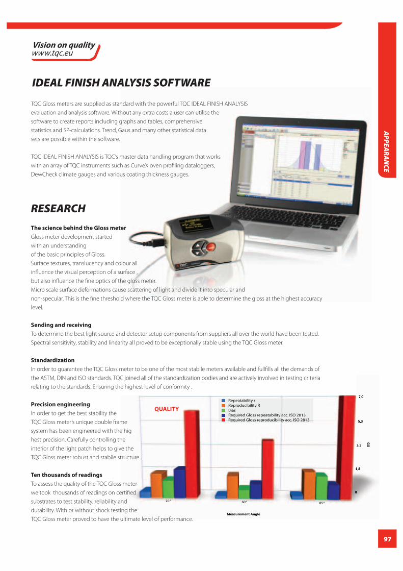
97
GU
Measurement Angle
Repeatability rReproducibility RBiasRequired Gloss repeatability acc. ISO 2813Required Gloss reproducibility acc. ISO 2813
° ° °
QUALITY
TQC Gloss meters are supplied as standard with the powerful TQC IDEAL FINISH ANALYSIS
evaluation and analysis software. Without any extra costs a user can utilise the
software to create reports including graphs and tables, comprehensive
statistics and SP-calculations. Trend, Gaus and many other statistical data
sets are possible within the software.
TQC IDEAL FINISH ANALYSIS is TQC’s master data handling program that works
with an array of TQC instruments such as CurveX oven profi ling dataloggers,
DewCheck climate gauges and various coating thickness gauges.
RESEARCHThe science behind the Gloss meter
Gloss meter development started
with an understanding
of the basic principles of Gloss.
Surface textures, translucency and colour all
infl uence the visual perception of a surface ,
but also infl uence the fi ne optics of the gloss meter.
Micro scale surface deformations cause scattering of light and divide it into specular and
non-specular. This is the fi ne threshold where the TQC Gloss meter is able to determine the gloss at the highest accuracy
level.
Sending and receiving
To determine the best light source and detector setup components from suppliers all over the world have been tested.
Spectral sensitivity, stability and linearity all proved to be exceptionally stable using the TQC Gloss meter.
Standardization
In order to guarantee the TQC Gloss meter to be one of the most stabile meters available and fullfi lls all the demands of
the ASTM, DIN and ISO standards. TQC joined all of the standardization bodies and are actively involved in testing criteria
relating to the standards. Ensuring the highest level of conformity .
Precision engineering
In order to get the best stability the
TQC Gloss meter’s unique double frame
system has been engineered with the hig
hest precision. Carefully controlling the
interior of the light patch helps to give the
TQC Gloss meter robust and stabile structure.
Ten thousands of readings
To assess the quality of the TQC Gloss meter
we took thousands of readings on certifi ed
substrates to test stability, reliability and
durability. With or without shock testing the
TQC Gloss meter proved to have the ultimate level of performance.
IDEAL FINISH ANALYSIS SOFTWARE
APPEA
RAN
CE
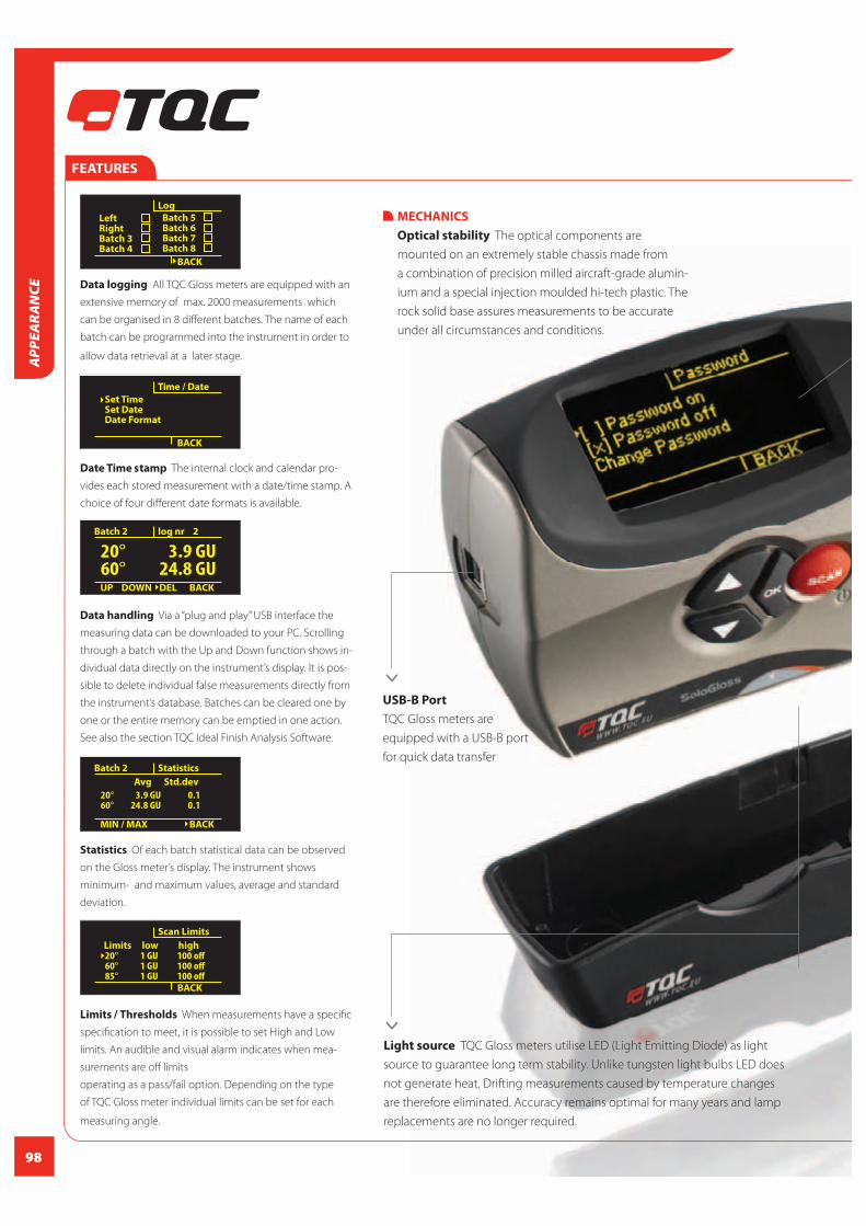
98
Data logging All TQC Gloss meters are equipped with an
extensive memory of max. 2000 measurements which
can be organised in 8 different batches. The name of each
batch can be programmed into the instrument in order to
allow data retrieval at a later stage.
Date Time stamp The internal clock and calendar pro-
vides each stored measurement with a date/time stamp. A
choice of four different date formats is available.
Data handling Via a “plug and play” USB interface the
measuring data can be downloaded to your PC. Scrolling
through a batch with the Up and Down function shows in-
dividual data directly on the instrument’s display. It is pos-
sible to delete individual false measurements directly from
the instrument’s database. Batches can be cleared one by
one or the entire memory can be emptied in one action.
See also the section TQC Ideal Finish Analysis Software.
Statistics Of each batch statistical data can be observed
on the Gloss meter’s display. The instrument shows
minimum- and maximum values, average and standard
deviation.
Limits / Thresholds When measurements have a specific
specification to meet, it is possible to set High and Low
limits. An audible and visual alarm indicates when mea-
surements are off limits
operating as a pass/fail option. Depending on the type
of TQC Gloss meter individual limits can be set for each
measuring angle.
Set TimeSet DateDate Format
Time / Date
BACK
MECHANICS
Optical stability The optical components are
mounted on an extremely stable chassis made from
a combination of precision milled aircraft-grade alumin-
ium and a special injection moulded hi-tech plastic. The
rock solid base assures measurements to be accurate
under all circumstances and conditions.
Left RightBatch 3Batch 4
Log
Batch 5 Batch 6Batch 7Batch 8
BACK
UP DOWN DEL
log nr 2
BACK
Batch 2
20°60°
3.9 GU24.8 GU
MIN / MAX
Statistics
BACK
Batch 2
20°60°
3.9 GU24.8 GU
Avg Std.dev
0.10.1
Scan Limits
20°60°85°
1 GU1 GU1 GU
Limits low high100 off100 off100 offBACK
Light source TQC Gloss meters utilise LED (Light Emitting Diode) as light
source to guarantee long term stability. Unlike tungsten light bulbs LED does
not generate heat. Drifting measurements caused by temperature changes
are therefore eliminated. Accuracy remains optimal for many years and lamp
replacements are no longer required.
>
USB-B Port
TQC Gloss meters are
equipped with a USB-B port
for quick data transfer
>
FEATURES
APP
EARA
NCE

99
CALIBRATION
In production TQC Gloss meters are
calibrated against a series of reference
tiles certified by the German BAM
(Bundesanstalt für Material-forschung
und -prüfung). Each Gloss meter comes
with a protective holder with integrated
calibration standard for field calibration.
Power saving The instrument utilises low power
consuming LED light sources and a battery friendly OLED
display. A full set of batteries has a 10.000 reading life
expectancy. However, in order to get the maximum op-
erational life from the batteries the instrument is equipped
with an adjustable “auto power off” function which can
be set by the user between 1 and 59 minutes. Power is
provided by two standard AA-batteries.
Languages The instrument is designed for optimal user
comfort. Use of a manual is hardly required due to the
intuitive menu driven user interface . To make life even
easier the TQC Gloss meter comes in a wide selection
of languages. Standard languages are English, German,
French, Spanish and Italian but the number of languages
will grow over time. Check our website for the latest status.
Scan mode Keeping the “Scan button” pressed down
allows the gloss meter to measure continuously at a rate
of approximately 70 readings per minute. If selected the
readings will be stored in the instrument’s memory.
Login Protection To prevent unwanted change of set-
tings by unauthorised users certain functions can be pro-
tected with a Login Code. The protection can be activated
or de-activated by choice. This code is user programmable.
Instrument setup, limit changes, delete readings, or clear
memory are all protected by the selected code.
Calibration The protective holder has an integrated
calibration standard for field calibration.
ERGONOMICS
OLED Display TQC Gloss meters are
equipped with the latest OLED (Organic
Light Emitting Display). This new type
of display offers extremely high visibility
and contrast at a range of viewing
angles. The innovative OLED display is
positioned at an angle of 35 degrees
which ensures excellent readability in
all conditions. When measuring on hori-
zontal or vertical surfaces or any angle
in between.
Operation Menu driven operation
allows new users to benefit from all
the features of the instrument without
having to refer to the user’s manual.
The intuitive structure guides the user
through the different screens to change
the settings of the instrument.
Shape The case of the instrument is
designed to comfort both right- and
left handed users. The upper part is “soft
touch” coated for ultimate grip and the
wrist strap prevents accidental drops.
The rubber operating buttons offer a
pleasant feel and user friendly opera-
tion.
Power saving
59 min
POWER OFF IN
Language
EnglishDeutschFrancaisItaliano
BACK
<SCAN>
Scan
MENU
20°60°
10297.9
Password
[ ] Password on[ ] Password offChange Password
BACK
x
Calibration
CalibrateCalbr. Values
BACK
>
>
>
>
FEATURES
APPEA
RAN
CE

100
20˚ 60˚ 85˚Range 0-2000 GU 0-2000 GU 0-2000 GU
Repeatability r* 0,4 GU 0,2 GU 0,2 GU
Reproducibility R* 1,7 GU 1,6 GU 1,9 GU
Bias* 1,2 GU 0,6 GU 1,6 GU
*Acc. ISO 2813 (range 0-100 GU)
WARRANTY
TQC will grant a warranty for a period of 12
months for TQC Gloss meter and 12 months
for all related equipment from the date of
delivery in respect of any evidence of faulty
workmanship and materials. TQC will extend
the warranty for TQC Gloss meter to a period
of 24 months from the date of delivery if
TQC Gloss meter is licensed via the
TQC Ideal Finish Analysis software.STANDARDS
ISO 2813
ASTM D523
ASTM D2457
ASTM C584
AS 1580 (602.2)
BS 3900 D5
DIN 67530
JIS Z 8741
ISO 7668
MFT 30064 (exception 45˚ angle)
ORDERING INFORMATION TQC GLOSS METERS
Art. N
GL0010 TQC SoloGloss 60˚
GL0020 TQC DuoGloss 20˚/60˚
GL0030 TQC PolyGloss 20˚/60˚/85˚
Scope of supply: 2 AA type batteries, Plastic protective case, Screwdriver,
USB stick with TQC Ideal Finish Analysis software, Micro fi bre cleaning
towel, USB cable, Calibration certifi cate
OperationalCalibration standard: Integrated tile in dust cover
Display High Contrast OLED display
Light source Extreme low drift LED light source
Power source 2x AA alkaline batteries
Batches max 8
Readings per batch max 500, non-dependant of
number of angles
Total max Readings 2000 readings with time stamp
Scan function Yes
Statistics Min. / Max. / Avg. / Std.dev /
number of measurements
Security Password protection
Software TQC Ideal Finish Analysis
DimensionsSize 90 x 140 x 45 mm (h x w x d)
3,5 x 5,6 x 1,7 “ (h x w x d)
Weight 398 g / 13,7 oz
TECHNICAL SPECIFICATIONS TQC GLOSS METERS
MeasurementBase dimensions 45 x 130mm / 1,7x5,1”
Orifi ce size 10 x 50mm / 0,4x2,0”
Spot size ≈ 5 x 5 mm / 0,2x0,2” @ 20˚
≈ 20 x 9 mm / 0,8x0,35” @ 60˚
≈ 40 x 9mm / 1,5x0,35” @ 85˚
Measurement speed 70 measurements per minute
at 3 angles
Simultaneous measurement 3 geometries
Power saver option User selectable
Units Gloss Units (GU)
Resolutions 0,1 GU (0-100GU) / 1GU (>100GU)
APP
EARA
NCE

101
COLORBOX - ILLUMINATED ASSESSMENT CABINETS
TQC Colorboxes offer an extensive range of illumination
conditions for any visual inspection. The multiple selectable
light sources allow assessment of gloss, structure, dam-
ages and metamerism. The Colorboxes are available in 60
and 120cm width. All are supplied with removable viewing
table and runtime counter. Both interior and exterior are
finished to the highest quality standard. The ability to switch
between light sources without flickering makes the cabinet
extremely stable. TQC Colorboxes are equipped with a 110 /
220 V switch.
STANDARDS
ISO 3664
ISO 3668
ASTM D1729
FEATURES
Strong MDF Flicker free “instant on” 5 different lightsources Inside painted in neutral Munsell N5,5 gray 110 / 220 V switch
Material Cabinet MDF
Material Light box Metal
Power Supply AC 110/220V, 50/60Hz
Power Less than 300W
TECHNICAL SPECIFICATIONS COLORBOX - ILLUMINATED ASSESSMENT CABINETS
ORDERING INFORMATION COLORBOX - ILLUMINATED ASSESSMENT CABINETS
Model VF0600 VF1200
Inner dimensions 680x360x380 mm, 1280x590x590 mm,
26.7x4.2x15 inch 50.4x23.2x23.2 inch
Outer dimensions 710x405x570 mm, 1310x610x800 mm,
27.9x15.9x22.4 inch 51.6x24.0x31.5 inch
Weight 28 kg / 61.8 lbs. 60 Kg / 132.3 lbs
Light sources 4 x light bulb type “A” 40 W E 27 6 x light bulb type “A” 40 W E 27
2 x light tube “shop light” TL84 (F11) 60 cm 2 x light tube “shop light” TL84 (F11) 120 cm
2 x light tube “day light” D65, 60 cm 2 x light tube “day light” D65, 120 cm
2 x light tube “day light” D5000 (D50) 60 cm 2 x light tube “day light” D5000 (D50) 120 cm
1 x light tube “black light” UV 60 cm 1 x light tube “black light” UV 60cm
ACCESSORIES / SPARES
Art.no Description Description on the lamp
Light sources VF0605 light tube type “A” 40 W E 27 E27
VF0600 VF0606 light tube “shop light” TL84 (F11) 60cm/23.6 inch TL84 18W / 940
VF0607 light tube “day light” D65, 60 cm/23.6 inch D65 18W / 965
VF0610 light tube “day light” D5000 (D50) 60cm/23.6 inch D50 18W / 950
VF0609 light tube “black light” UV 60cm/23.6 inch UV 18W / BLB
Light sources VF0605 light tube type “A” 40 W E 27 E27
VF1200 VF1205 light tube “shop light” TL84 (F11) 120cm/27.24 inch TL84 36W / 940
VF1206 light tube “day light” D65, 120 cm/27.24 inch D65 36W / 965
VF1209 light tube “day light” D5000 (D50) 120cm/27.24 inch D50 36W / 950
VF1208 light tube “black light” UV 120 cm/27.24 inch UV 36W / BLB
VF0603 45° viewing table
APPEA
RAN
CE

102
X-RITE RM200QC SPECTROCOLORIMETER
The X-Rite RM200QC Imaging Spectrocolorimeter bridges
the gap between color appearance and material
color - from incoming material batches to outgoing
product shipments - in an elegant, portable unit that fits
comfortably in your hand.
The RM200QC is designed to provide stable color
comparisons for materials and products wherever color
control Is important.
STANDARDS ASTM D2244
ISO 7724
ORDERING INFORMATION X-RITE RM200QC SPECTROCOLORIMETER
Art. No
VF0620 Spectrocolorimeter RM200QC
Scope of supply: Instrument, Carrying case, Pouch, USB cable, Software, Manual
FEATURES
Using 8 different visible illuminations and 1 UV LED (9 bands) 45/0 optical geometry Proprietary image capture technology Graphical Pass/Fail indicator Display of dE for all common methods i.e. CIELAB, CMC, CIE 94, 2000 Display of measured and delta differences with L*a*b*C*h° for standard and sample
Graphical L*a*b* plot Verbal color difference description 20 reference standards to store 350 sample measurements to store Creates PDF and CSV files USB Report Mode to PC Increased quality control
TECHNICAL SPECIFICATIONS X-RITE RM200QC SPECTROCOLORIMETER
* Minimum recommended tolerance 1.0 ΔE (limited to 0.8 ΔE as smallest settable tolerance)
Display 45 mm / 1,77 inch Color TFT
Data Interface USB (Mass Storage Device)
Operating Temp 0° to 40°C / 50° to 104°F
Storage temp -20° to 60°C / -4° to 140°F
Humidity Range 20-80% RH (non-condensing)
Usage Indoor use only
Altitude 2000 m / 78740 inch
Pollution Degree 2
Transient Overvoltage Category II
Languages English, German, France, Italian, Spanish
Power Internal Lithium-ion batteries
APP
EARA
NCE
Measuring Geometrics 45/0 Image Capture
Light Source Independent tri-directional 25 LED,
(8* visible wavelengths; 1* UV)
Illuminant/Observer D65/10 and A/10
Standards/Sample Storage 20/350
Measurement time 1,8 seconds
Measuring Area 4 & 8 mm
Minimum recommended 1.0° (limited to 0.8° as smallest
tolerance settable tolerance)
Calibrationtile Slide system integrated
Short Term Repeatability Typical 0,10 DE 94 on white (D65 /10)

103
RAL K7 COLOUR FAN DECK
The classic RAL fan deck with
all 213 RAL CLASSIC colours
at a glance. Every page
contains fi ve colours, which
makes the fan deck very
convenient and practical.
ORDERING INFORMATION RAL K7 COLOUR FAN
Art. No
VF6606 RAL K7 classic colour fan deck
Fan deck size 50x150 mm / 1,97x5,91 inch
Colour illustration 20x 50 mm / 0,97x1,97 inch
Colours per sheet 5
Colours 213
Weight 150 g / 5,29 oz
Dimensions 150x50x15 mm /
5,91x1,97x0,59 inch
TECHNICAL SPECIFICATIONS RAL K7 COLOUR FAN
FEATURES
Gloss Five colours per page Personalized company imprint available
Dimensions 57x57x155 mm / 2,24x2,24x6,1 inch
Weight 450 g / 15,87 oz
Colour illustration 50x150 mm / 1,97x5,91 inch
Colours per sheet 1
Colours 213
TECHNICAL SPECIFICATIONS FAN DECK RAL K5 CLASSIC COLOUR
FAN DECK RAL K5 CLASSIC COLOUR
Colour fan deck containing
all 213 RAL Classic colours.
FEATURES
Semi matt or gloss U-shaped protective cover Well-suited for colour combination and colour comparison Personalized company imprint available
Art. No
VF6607 Fan deck RAL K5 Classic colour – semi matt
VF6607/1 Fan deck RAL K5 Classic colour – gloss
ORDERING INFORMATION FAN DECK RAL K5 CLASSIC COLOUR
APPEA
RAN
CE

104
RING BINDER RAL K6
Ring binder with all 213 RAL
CLASSIC colours.
Dimensions A4 (210x297 mm / 8,27x11,96 inch
Colours per sheet 1
Colours 213
TECHNICAL SPECIFICATIONS RING BINDER RAL K6
FEATURES
Semi-matt A4 size Sheets also individually available
Art. No
VF6609 Ring binder RAL K6
ACCESSORIES / SPARES
VF6610 Single sheet, please specify colour
ORDERING INFORMATIONBOX RING BINDER RAL K6
BOOKLET RAL K1
Booklet with 210 RAL Classic
Colours.
Dimensions 105 x 200 mm / 4,13x7,87 inch
Colour Illustrations 52x15 mm / 2,01x0,59 inch
Colours per page 14
Binding Wire-O
TECHNICAL SPECIFICATIONS BOOKLET RAL K1
FEATURES
Gloss Available RAL K1 Individual full page corporate design on the front cover 14 colours per side Sheets divided in the middle for combining colours easily
ORDERING INFORMATION BOOKLET RAL K1
Art. No
VF6608 Booklet RAL K1
Scope of supply: Booklet with 210 RAL CLASSIC colours
APP
EARA
NCE

105
BOX WITH RAL 840-HR CLASSIC SEMI MATT
Primary standards of all 213
RAL Classic colours.
FEATURES
Semi matt Binding colour samples for colour matching and quality control Including X-Y-Z-values, colour distance from the original standard and Reflectance curve Cards are also individually available
Art. No
VF6600 Box with RAL 840-HR Classic Colour cards
ORDERING INFORMATION BOX WITH RAL 840-HR CLASSIC COLOURS
ACCESSORIES / SPARES
VF6601 Box for RAL Classic 840-HR Classic Colours
VF6602 RAL-840-HR Single sheet, please specify colour
Cardsize A5 (148x21 mm / 5,83x8,27 inch)
Colour illustration A6-sized (105 x148 mm/ 4,13x5,83 inch)
Colours per card 1
Colours 213 single cards
TECHNICAL SPECIFICATIONS BOX WITH RAL 840-HR CLASSIC COLOURS
BOX WITH RAL 841-GL CLASSIC HIGH GLOSSCOLOURSPrimary standards of all 196
Ral classic colours
Cardsize A5-sized (148 x 210 mm / 5,83x8,27 inch)
Colour illustration A6-sized (105 x 148 mm / 4,13x5,83 inch )
Colours per sheet 1
Colours 196
TECHNICAL SPECIFICATIONS BOX WITH RAL 841-GL
ORDERING INFORMATION BOX WITH RAL 841-GL
Art. No
VF6603 Box RAL 841-GL Classic colours box with
196 classic colour cards
VF6604 Box for RAL Classic 841-GL color register
VF6605 RAL 841-GL, Single sheet, please specify colour
FEATURES
High gloss Binding colour samples for colour matching and quality control Including X-Y-Z-values, colour distance from the original standard and reflectance curve Cards are also individually available
APPEA
RAN
CE
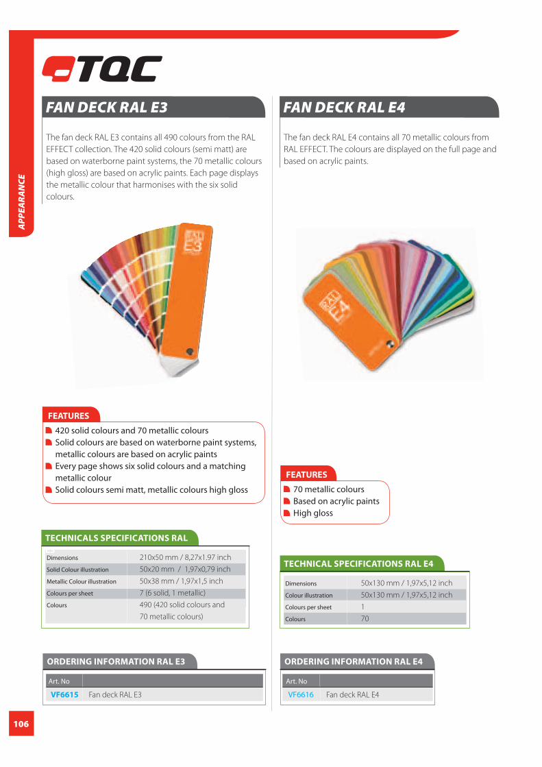
106
APP
EARA
NCE
FAN DECK RAL E4
The fan deck RAL E4 contains all 70 metallic colours from
RAL EFFECT. The colours are displayed on the full page and
based on acrylic paints.
ORDERING INFORMATION RAL E4
Art. No
VF6616 Fan deck RAL E4
Dimensions 50x130 mm / 1,97x5,12 inch
Colour illustration 50x130 mm / 1,97x5,12 inch
Colours per sheet 1
Colours 70
TECHNICAL SPECIFICATIONS RAL E4
FEATURES
70 metallic colours Based on acrylic paints High gloss
FAN DECK RAL E3
The fan deck RAL E3 contains all 490 colours from the RAL
EFFECT collection. The 420 solid colours (semi matt) are
based on waterborne paint systems, the 70 metallic colours
(high gloss) are based on acrylic paints. Each page displays
the metallic colour that harmonises with the six solid
colours.
ORDERING INFORMATION RAL E3
Art. No
VF6615 Fan deck RAL E3
Dimensions 210x50 mm / 8,27x1.97 inch
Solid Colour illustration 50x20 mm / 1,97x0,79 inch
Metallic Colour illustration 50x38 mm / 1,97x1,5 inch
Colours per sheet 7 (6 solid, 1 metallic)
Colours 490 (420 solid colours and
70 metallic colours)
TECHNICALS SPECIFICATIONS RAL
E3
FEATURES
420 solid colours and 70 metallic colours Solid colours are based on waterborne paint systems, metallic colours are based on acrylic paints Every page shows six solid colours and a matching metallic colour Solid colours semi matt, metallic colours high gloss
APP
EARA
NCE

107
SINGLE SHEETS RAL EFFECT
Colour sample sheet of either one of the 70 metallic Effect
colours, or one of the 420 RAL Effect solid colours.
ORDERING INFORMATION SINGLE SHEETS RAL EFFECT
Art. No
VF6617 Single sheet RAL Effect Solid, please specify colour
VF6618 Single sheet RAL Effect Metallic, please specify colour
FEATURES
High gloss A6 size Single sheets
Dimensions 105x148 mm / 4,13x5,83 inch
Colour illustration 105x148 mm / 4,13x5,83 inch
Colours per sheet 1
TECHNICAL SPECIFICATIONS SINGLE SHEETS RAL EFFECT
BOX WITH RAL E1 COLOURS
The primary standards in the box RAL E1 of all 490 RAL
EFFECT colours serve as binding colour samples for colour
matching and quality control. The 420 solid colours (semi
matt) are based on waterborne paint systems, the 70
metallic colours (high gloss) are based on acrylic paints.
Card size A6 (105 x 148 mm / 4,13x5,83 inch )
Colour illustration 105x138mm / 4,13x5,43 inch
Colours per sheet 1
Colours 490 (420 solid colours, 70 metallic
colours)
TECHNICAL SPECIFICATIONS BOX WITH RAL E1
FEATURES
420 solid colours and 70 metallic colours in a high grade box Based on waterborne paint systems Solid colours semi matt, metallic colours high gloss
ORDERING INFORMATION BOX WITH RAL E1
Art. No
VF6612 Box with RAL E1 Colours
ACCESSORIES / SPARES
VF6613 RAL E1 Single sheet, please specify colour
APPEA
RAN
CE

108
Dimensions 290x50 mm / 11,42x1.97 inch
Solid Colour illustration 50x25 mm / 1,97x0,98inch
Colours per sheet 9
Colours 1625
TECHNICAL SPECIFICATIONS COLOUR FAN DECK RAL D2 IN BOX
RAL D2 DESIGN IN BOX
Colour fan deck RAL D2 in box containing all 1625 RAL
DESIGN colours.
FEATURES
All 1625 RAL Design colors, incl. 26 new pastel colours New clear classification system, arrangement of colours by the criteria hue (H), lightness (L) and chroma (C) Semi matt
Art. No
VF6619 Colour fan deck RAL D2 design in box
ORDERING INFORMATION COLOUR FAN DECK RAL D2 IN BOX
SINGLE SHEETS RAL DESIGN
Colour sample sheet of all
RAL Design colours.
FEATURES
A6-sized (105x148 mm / 4,13x5,83 inch) A4-sized (210x297 mm / 8,27 x11,69 inch) All 26 new pastel colours Spectrophotometrically documented upon request Complete set in a box
Dimensions 105x148 mm / 4,13x5,83 inch A6
210x297 mm / 8,27 x11,69 inch A4Colour illustration 105x148 mm / 4,13x5,83 inch A6
210x297 mm / 8,27 x11,69 inch A4Colours per sheet 1
TECHNICAL SPECIFICATIONS SINGLE SHEETS RAL DESIGN
Art. No Sheet size spectro Sheet photometrically documented
VF6620 105x148 mm / - Single sheet,
4,13x5,83 inch A6 please specify
colour
VF6621 105x148 mm / - Complete
4,13x5,83 inch A6 set in box
VF6622 105x148 mm / yes Complete
4,13x5,83 inch A6 set in box
VF6623 105x148 mm / yes Single sheet,
please specify
colour
VF6624* 210x297 mm / - Single sheet,
8,27 x11,69 inch A4 please specify
colour
VF6625* 210x297 mm / - Complete
8,27 x11,69 inch A4 set in ringbinder
*The 89 dark shades which are no longer included in the revised RAL
DESIGN system are still available as A4-sized single sheets
ORDERING INFORMATION SINGLE SHEETS RAL DESIGN
APP
EARA
NCE

109
RAL PLASTICS
RAL P1 (100 classical colourplates) and RAL P2 (200 design
colourplates) in plastic. 300 design options for precise
colour communication and innovative products. RAL P2
contains 160 opaque and 40 special, transparent colours.
Together with the 100 classic shades within RAL P1 the
RAL PLASTICS colour standard now comprises 300 colour
samples. Each colour is also available as a single plate. The
RAL PLASTICS colour samples are multifunctional and offer
many benefits in practice. Three different surface textures
and three different material thicknesses give users a
realistic impression of how the colours will look when used
with different material applications.
With the introduction of RAL PLASTICS the inaccuracies,
that were often unfortunate by-products of the old method
of translating RAL paint samples into plastics colours, now
belong to the past. This means that plastics
manufacturers and plastics processors can
now save time, costs and raw materials.
FEATURES
Three levels of thickness – 3mm, 2mm and 1mm / 0,12, 0,08, 0,04 inch – show each colour at different levels of opacity Three different surface textures – high gloss polished, VDI 24 and VDI 42 – show users the colour dependent on surface roughness The protective sleeve for each RAL P1 PLASTICS sample contains masterbatch code,colormetric mea sures, absolute values, reflectance curve, distance to the plastics original standard
ORDERING INFORMATION RAL PLASTICS
Art. No RAL P1 RAL P2
VF6627 Complete set in box -
VF6628 Single plate, please specify colour -
VF6629 - Complete set in box
VF6630 - Single plate, please specify colour
VF6631 Complete set in box Complete set In box
APPEA
RAN
CE
TECHNICAL SPECIFICATIONS RAL PLASTICS
Material polypropylene
Colours P1 100
Colours P2 300
Dimensions Colour plate 105×148×3mm / 4,13x5,83x0,12 inch

110
SOFTWARE RAL DIGITAL
Software on flash memory for designers, architects, interior designers and
everyone else who works creatively with colour. RAL DIGITAL lets you navigate
your way around the entire spec- trum and gamut of RAL colour space, quickly
locating the perfect shade based on any and every criterion for locating the
precise match or selecting beautiful harmonizing colours to almost any
specification. It enables integration of all 2, 328 RAL colours into popular
Graphics and CAD programs with simple import and export file formats.
FEATURES
Contains all RAL EFFECT colours, RAL CLASSIC colours and RAL DESIGN colours for graphics and CAD programs Colour values include RGB, HEX, CMYK, LAB, HLC, XYZ colorimetric data Inspirational colour harmony recommendations based on monochromatic, adjacent, analogous and comple- mentary colour combinations Find the perfect colour set based on simple text descriptions of your colour needs Colour search: Find RAL colours based on matches to current commonly used colour collections or compared to colorimetric values Generate and store or export your own colour data for integration into most major design and CAD programs, or simple text format for document or spreadsheet analysis Colour harmony – calculates harmonious colour compositions based on an original colour
Next RAL colour – converts the colours that correspond to an original colour into the RAL system (e.g. NCS -> RAL) Colour values – displays the exact Lab/HLC/RGB/HEX and CMYK colour values of all the RAL colours in RAL CLASSIC, RAL EFFECT and RAL DESIGN Colour designer – colourises images using the colours required Colour pipette – extracts the RGB colour values from any file type Colour overviews – verify the precision of the RAL colour palettes in individual systems Palette installer – easily integrates RAL colour palettes into approx. 30 software products in the architecture and graphic design areas (Photoshop, Corel, Nemetschek and many others) Complementary colours – calculates colour opposites, complementary contrasts and true harmonies
ORDERING INFORMATION SOFTWARE RAL DIGITAL
Art. No
VF6632 Software RAL Digital
APP
EARA
NCE

111
TECHNICAL SPECIFICATIONSRAL BOOK COLOUR MASTER AND FAN DECK E3
Book
Dimensions 300x340 mm / 11,81x13,39 inch
Pages 328
Language: Bilingual: German/English
Fan deck Dimensions 210x50 mm / 8,27x1.97 inch
Solid Colour illustration: 50x20 mm / 1,97x0,79 inch
Metallic Colour illustration 50x38 mm / 1,97x1,5 inch
Colours per sheet: 7 (6 solid, 1 metallic)
Colours 490
(420 solid colours and 70 metallic colours)
ORDERING INFORMATION RAL BOOK COLOUR MASTER AND FAN DECK E3
Art. No
VF6642 RAL Book Colour Master and Fan deck E3
Scope of supply: RAL Book Colour Master and RAL E3 Fan deck
FEATURES
Encoded in 490 RAL EFFECT colours For architects, designers, artists and other creative minds Attached stencils for colour combinations
APPEA
RAN
CE
FEATURES
120 adjectives related to the health care sector Coded in 340 RAL DESIGN System colours For architects, designers and advertisers in the health care sector With practically and relevant design examples Includes a template for colour combinations
TECHNICAL SPECIFICATIONS RAL BOOK AND FAN DECK COLOURS OF HEALTH AND CARE
Book
Dimensions 240x260 mm / 9,45x10,24 inch
Pages 384
Language Bilingual: German/English
Fan deckDimensions 87x214 mm / 3,43x8,43 inch
Colours per page 4
Colours 120
ORDERING INFORMATION RAL BOOK AND FAN DECK COLOURS OF HEALTH AND CARE
Art. No
VF6640 Book and Fan deck Colours of health and care
Scope of supply: Book and fan deck Colours of health and care
ACCESSORIES / SPARES
Vf6626 Fan deck Colours of health and care
Colours of health and care pres-
ents 120 current terms from the
health care sector and their co-
lour translation into the RAL DE-
SIGN System. On the one hand,
the work considers the Colours
of Health and Care regarding co-
lour theoretical-artistic aspects,
and on the other hand with an
analytical-scientifi c approach and serves as planning aid for
a patient-friendly, eff ective, humane-aesthetic colour design
for all fi elds of the health care system: the practice, hospital
or rehabilitation centre, the hotel, retirement home or living-
at-home at old age.
RAL COLOURS OF HEALTH AND CARE
RAL COLOUR MASTER
Interactive design
book for creative
minds. Experi-
ment with and
combine colours,
shapes, patterns
and images.
Colour Master
contains 328
pages of bulging colourfulness in shapes, patterns and im-
ages. Every single page of the book is an individual creative
experimen-ting tool for the user. All colour displays are
encoded in the 490 RAL EFFECT colours.
The fan deck shows the 490 RAL EFFECT colours – 420 solid
colours and 70 metallic colours.

112
Which colours do people consider ‘exotic’, which seem
‘glamorous’ in their eyes and which colours are ‘spirited’? The
colour dictionary answers all these questions and translates
360 adjectives into colour compositions linked to the RAL
DESIGN System.
The colour
dictionary is an
indispensable work
tool for advertisers,
architects, interior
designers, design-
ers, professional
painters and all
those who are
fascinated by the
world of colour. For each of the 360 adjectives,
the book displays 49 colour images and the respective
colour scale in RAL DESIGN System colours. This is what
makes Professor Venn’s colour dictionary diff erent from
other colour theory books, which usually only list one colour
for each concept. The colour dictionary gives the user room
to play with and opens up a whole range of possibilities for
making colour statements.
FEATURES
360 adjectives expressed in colour compositions Displayed in RAL DESIGN System colours Based on a scientifi c study The standard work for advertising, interior design, design and teaching
TECHNICAL SPECIFICATIONS RAL BOOK – THE COLOUR DICTIONARY
Dimensions 240x260 mm / 9,45x10,24 inch
Pages 864
Language Bilingual: German/English
ORDERING INFORMATION RAL BOOK – THE COLOUR DICTIONARY
Art. No
VF6639 RAL Book – The colour dictionary
RAL BOOK – THE COLOUR DICTIONARY
RAL BOOK COLOURS FOR HOTELS
Hotels want to be
places of comfort and
relaxation. Besides a
top service, the hotel
ambience and the
right colour
combinations create
a welcoming and
comforting
atmosphere. To
achieve this, the
design book
COLOURS FOR
HOTELS has been published
in Callwey publishing house.
Dimensions 240x260 mm / 9,45x10,24 inch
Pages 416
Language Bilingual: German/English
TECHNICAL SPECIFICATIONS RAL BOOK COLOURS FOR HOTELS
ORDERING INFORMATION RAL BOOK COLOURS FOR HOTELS
Art. No
VF6643 Book Colours for hotels
APP
EARA
NCE
FEATURES
Coded in the RAL DESIGN system Based on a scientifi c study For architects, designers, investors, building owners, hotel managers and advertisers in the hotel industry With practically and relevant design examples Includes a template for colour combinations
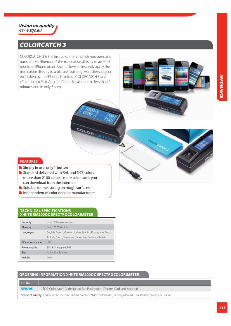
113
APPEA
RAN
CE
COLORCATCH 3
COLORCATCH 3 is the first colorimeter which measures and
transmits via Bluetooth® the true colour directly to an iPod
touch, an iPhone or an iPad. It allows to instantly apply the
true colour directly to a picture (building, wall, dress, object
etc.) taken by the iPhone. Thanks to COLORCATCH 3 and
«Colorix.com Pro» App for iPhone it’s all done in less than 2
minutes and in only 3 steps.
ORDERING INFORMATION X-RITE RM200QC SPECTROCOLORIMETER
Art. No
VF0705 TQC Colorcatch 3, designed for iPod touch, iPhone, iPad and Android
Scope of supply: CorlorCatch3 incl. RAL and NCS colors, Nylon belt holder, Battery, Manual, 3 calibration plates, USB cable
FEATURES
Simply in use, only 1 button Standard delivered with RAL and NCS colors (more than 2100 colors), more color cards you can download from the internet. Suitable for measuring on rough surfaces Independent of color or paint manufacturers
TECHNICAL SPECIFICATIONS X-RITE RM200QC SPECTROCOLORIMETER
Capacity over 2000 measurements
Memory over 100.000 colors
Languages English, French, German, Italian, Spanish, Portuguese, Dutch,
Turkish, Czech, Slovenian, Catalonian, Finish and Polish
PC communication USB
Power supply 9V alkaline type 6LR61
Size 120 X 40 X 35 mm
Weight 99 gr

114
FILM THICKNESSA correct paint- or coating thickness is an important parameter in the surface treatment industry. The performance of a
coating system is based upon correct application of this system following the paint manufacturers specifi cation sheet.
Each layer from primer to topcoat and individual intermediate layers are exactly specifi ed with a minimum and maxi-
mum coating thickness. Often both a dry and wet fi lm thickness is specifi ed.
Although the dry fi lm is the leading parameter often the wet fi lm is measured during application in order to give the
operator an indication of the applied wet fi lm thickness. Measuring wet fi lm thickness during application identifi es the
need for immediate correction and adjustment by the applicator. The relationship between dry and wet fi lm thickness
depends on the volume of solids in the coating. The applied wet fi lm thickness depends on many variables such as the
type of coating, application method (air pray, brush, roller, airless spray, electrostatic, tribo gun, etc.), equipment qua-
lity, operator, substrate material, the size and shape of the part etc.. Incorrect coating thickness could lead to technical
problems or excessive costs.
Too low dry fi lm thickness can lead to:
COAT
ING
TH
ICKN
ESS
Too high fi lm thickness causes problems like:

115
COATIN
G TH
ICKNESS
Multiple layer systems are often measured layer by layer. After cure of each layer a large number of measurements are
made and stored so statistics of each following paint layer can be compared with the previous layer to defi ne the thick-
ness of each individual paint fi lm. .
Techniques and systems
There are many diff erent techniques and systems to measure coating thickness. The choice of coating thickness gauge
type depends on type of application, substrate properties, budget and other requirements. The following type of instru-
ments are common in today’s coating and surface treatment industry:
Magnetic Pull-off
Magnetic pull-off gages are suitable for ferrous metal substrates only and use a permanent magnet combined with a
calibrated spring which is linked to a graduated scale. The magnetic force between the magnet and ferrous steel sub-
strate pulls the two together. The coating thickness separating the two makes it easier to pull the magnet away.
The more coating between magnet and steel the easier the pull. The actual coating thickness is determined by measur-
ing this pull-off force. Testing with magnetic gages is sensitive to surface roughness, curvature, substrate thickness, and
the make up of the metal alloy. Magnetic pull-off gages are rugged, simple, inexpensive, portable, and usually do not
require any calibration adjustment. They are a good, low-cost alternative in situations where electronic gauges are not
allowed due to explosion risk or when quality goals require only a few readings during production.

116
COAT
ING
TH
ICKN
ESS
Eddy Current
Eddy current techniques are used to nondestructively measure the thickness of nonconductive coatings on nonfer-
rous metal substrates. A coil of fi ne wire conducting a high-frequency alternating current (above 1 MHz) generates an
alternating magnetic fi eld at the surface of the instrument’s probe. When the probe is near to a conductive surface, the
alternating magnetic fi eld will set up eddy currents on the surface. The characteristics of the substrate and the distance
of the probe from the substrate (the coating/layer thickness) aff ect the level of the eddy currents. The eddy currents
create their own opposing electromagnetic fi eld that is sensed by the exciting coil or by a second, adjacent coil.
Modern dry fi lm thickness gauges often combine the magnetic induction and eddy current methods in one instru-
ment. These instruments are basically suitable to measure each non-magnetic layer on a magnetic surface or each
non-conductive layer on a conductive metal surface such a aluminum , copper, brass, stainless steel….
Magnetic and Electromagnetic Induction
These gauges are used to measure non-magnetic layers on magnetic (ferrous) surfaces. Magnetic induction instru-
ments use a permanent magnet to generate a magnetic fi eld. A magneto-resistor or Hall-eff ect generator is used to
sense the magnetic fl ux density at a pole of the magnet. Electromagnetic induction instruments use an alternating
magnetic fi eld. A soft, ferromagnetic rod wound with a coil of fi ne wire is used to produce a magnetic fi eld. A second
coil of wire is used to detect changes in magnetic fl ux. These advanced electronic instruments measure the change in
magnetic fl ux density at the surface of a magnetic probe as it comes close to a steel surface. The level of the fl ux density
at the probe surface is directly related to the distance from the steel substrate. By measuring fl ux density the coating
thickness or layer thickness can be determined.
Ultrasound or Ultrasonic
The ultrasonic pulse-echo technique is used to measure the thickness of coatings on nonmetal substrates (plastic,
wood, concrete etc.) without damaging the coating. The probe of the instrument contains an ultrasonic transducer that
sends a pulse through the coating. The pulse refl ects back from the substrate to the transducer and is converted into a
high frequency electrical signal. The echo waveform is digitized and analyzed to determine coating thickness. In some
circumstances, individual layers in a multi-layer system can be measured.
PIG or Destructive measuring
This method is often used on reference panels or in forensic inspections with failing coating systems. With this system a
precise incision is made with a special cutting tool perpendicular to the surface. An illuminated measuring microscope
is used to measure the width of the cut. Depending on the type of cutting tool the width is multiplied with a factor
which leads to the coating thickness. This system is ideal for those circumstances where electronic gauges cannot be
used. The thickness of individual layers can be determined as well with this system.
Wet fi lm thickness measuring
Wet-fi lm is most often measured with a wet fi lm comb or wheel. The wet-fi lm comb is a fl at precision plate with cali-
brated notches on the edge of each face. They are made of aluminum, plastic, or stainless steel. The gauges are placed
squarely and fi rmly onto the surface to be measured immediately after coating application and then removed. The wet-
fi lm thickness lies between the highest notch that touched the coating and the next uncoated notch. Wet fi lm thick-
ness (WFT) combs measurements are neither accurate nor sensitive, but they are useful in determining approximate
wet-fi lm thickness in an early stage of application of coatings on articles where size and shape prohibit the use of more
precise methods. A wet fi lm thickness wheel is a high precision, accurate and easy to use instrument which consists of
a set of three wheels. The central wheel is of a smaller diameter and is eccentric relative to the two outer wheels. The
wheel is rolled through the wet coating and the interface of where the inner wheel starts touching the paint indi-
cates the wet fi lm thickness. Better wet fi lm thickness wheels are equipped with roller bearings for smooth rolling and
knurled outer wheels to allow measurements to be taken on slippery coatings or on fast moving substrates such as coil
coating.
Air Ultrasound
An air-ultrasonic device can be used non-destructively / non-contact on uncured powder coatings on smooth metal
surfaces to predict the thickness of the cured fi lm before the powder coating is cured in the oven.
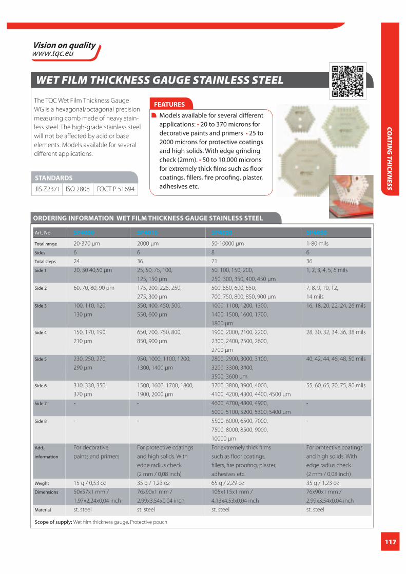
117
COATIN
G TH
ICKNESS
WET FILM THICKNESS GAUGE STAINLESS STEEL
The TQC Wet Film Thickness Gauge
WG is a hexagonal/octagonal precision
measuring comb made of heavy stain-
less steel. The high-grade stainless steel
will not be affected by acid or base
elements. Models available for several
different applications.
ORDERING INFORMATION WET FILM THICKNESS GAUGE STAINLESS STEEL
Art. No SP4000 SP4010 SP4020 SP4050
Total range 20-370 μm 2000 μm 50-10000 μm 1-80 mils
Sides 6 6 8 6
Total steps 24 36 71 36
Side 1 20, 30 40,50 μm 25, 50, 75, 100, 50, 100, 150, 200, 1, 2, 3, 4, 5, 6 mils
125, 150 μm 250, 300, 350, 400, 450 μm
Side 2 60, 70, 80, 90 μm 175, 200, 225, 250, 500, 550, 600, 650, 7, 8, 9, 10, 12,
275, 300 μm 700, 750, 800, 850, 900 μm 14 mils
Side 3 100, 110, 120, 350, 400, 450, 500, 1000, 1100, 1200, 1300, 16, 18, 20, 22, 24, 26 mils
130 μm 550, 600 μm 1400, 1500, 1600, 1700,
1800 μm
Side 4 150, 170, 190, 650, 700, 750, 800, 1900, 2000, 2100, 2200, 28, 30, 32, 34, 36, 38 mils
210 μm 850, 900 μm 2300, 2400, 2500, 2600,
2700 μm
Side 5 230, 250, 270, 950, 1000, 1100, 1200, 2800, 2900, 3000, 3100, 40, 42, 44, 46, 48, 50 mils
290 μm 1300, 1400 μm 3200, 3300, 3400,
3500, 3600 μm
Side 6 310, 330, 350, 1500, 1600, 1700, 1800, 3700, 3800, 3900, 4000, 55, 60, 65, 70, 75, 80 mils
370 μm 1900, 2000 μm 4100, 4200, 4300, 4400, 4500 μm
Side 7 - - 4600, 4700, 4800, 4900, -
5000, 5100, 5200, 5300, 5400 μm
Side 8 - - 5500, 6000, 6500, 7000, -
7500, 8000, 8500, 9000,
10000 μm
Add. For decorative For protective coatings For extremely thick films For protective coatings
information paints and primers and high solids. With such as floor coatings, and high solids. With
edge radius check fillers, fire proofing, plaster, edge radius check
(2 mm / 0,08 inch) adhesives etc. (2 mm / 0,08 inch)
Weight 15 g / 0,53 oz 35 g / 1,23 oz 65 g / 2,29 oz 35 g / 1,23 oz
Dimensions 50x57x1 mm / 76x90x1 mm / 105x115x1 mm / 76x90x1 mm /
1,97x2,24x0,04 inch 2,99x3,54x0,04 inch 4,13x4,53x0,04 inch 2,99x3,54x0,04 inch
Material st. steel st. steel st. steel st. steel
Scope of supply: Wet film thickness gauge, Protective pouch
FEATURES
Models available for several different applications: 20 to 370 microns for decorative paints and primers 25 to 2000 microns for protective coatings and high solids. With edge grinding check (2mm). 50 to 10.000 microns for extremely thick films such as floor coatings, fillers, fire proofing, plaster, adhesives etc.
STANDARDS
JIS Z2371 ISO 2808 ГОСТ Р 51694

118
COAT
ING
TH
ICKN
ESS
PLASTIC WET FILM COMB
The TQC Wet Film Comb made of plastic, to measure wet
film thickness between 25 and 900μm. The TQC Wet Film
Comb is designed as a disposable thickness gauge. It can
be kept as a record of wet film thickness measurement for
ISO or customer requirements.
One side of the comb
measures the wet film
thickness in μm (30
steps between 25
and 900μm), the
other side measures
in mills (30 steps
between 1 and 35 mils)
One set TQC Wet Film
Combs contains 500 pieces.
FEATURES
Ideal for record keeping In μm and mils
TECHNICAL SPECIFICATIONS PLASTIC WET FILM COMB
Total range 25 to 900 μm
Sides 6
Total steps 30
Side 1 25, 51,76, 102, 127 μm 1, 2, 3, 4, 5 mils
Side 2 152, 178, 203, 229, 254 μm 6, 7, 8, 9, 10 mils
Side 3 279, 305, 330, 356, 381 μm 11, 12, 13, 14, 15 mils
Side 4 406, 432, 457, 483, 508 μm 16, 17, 18, 19, 20 mils
Side 5 533, 559, 584, 610, 635 μm 21, 22, 23, 24, 25 mils
Side 6 660, 737, 787, 832, 900 μm 27, 29, 31, 33, 35 mils
Weight 4 g / 0,14 oz
Dimensions 58x58x0,8 mm / 2,28x2,28x0,03 inch
Material Plastic
ORDERING INFORMATION WET FILM MEASURING COMB
Art. No
LD2020 Plastic wet film comb, 500 pieces
Scope of supply: TQC Wet Film Combs 500 pieces

119
COATIN
G TH
ICKNESS
WET FILM THICKNESS WHEEL
Specially by TQC developed instrument for use on wet
lacquers, paint and coil coated surfaces. Equipped with a
precision roller-bearing for smooth rolling over the
surface . The wheel has three rims, the inner rim being
eccentric to the two outer rims. The outer rings are notched
for a firm grip in the surface to prevent slipping. Made of
stainless steel and with an aluminum grip.
STANDARDS
JIS Z2371 ISO 2808 ГОСТ Р 51694
FEATURES
Precision roller bearing Slipping prevention Stainless steel with aluminum grip
ORDERING INFORMATION WET FILM THICKNESS WHEEL
Art. No VF2255 VF2256 VF2257
Measuring 0-100 μm 0-300 μm 0-600 μm
range
Accuracy better than better than better than
3 micron 3 micron 3 micron
Division 10 μm 30 μm 60 μm
Dimensions 90x22x22 mm / 115x22x22 mm / 140x22x22 mm /
3,54x0,87x0,87 4,52x0,87x0,87 5,51x0,87x0,87
inch inch inch
Weight 148 g / 5,22 oz 148 g / 5,22 oz 150 g / 5,29 oz
Material st. steel / st. steel / st. steel /
aluminum aluminum aluminum
Scope of supply: Wet film thickness wheel , Calibration certificate,
Leather pouch
CCICALIBRATION
CERTIFICATION
INCLUDED
WET FILM MEASURING COMB
Rectangular promotion measuring comb with a range of
25 to 2000 μm. Made of top-quality, weather-resistant alu-
minum. Special printing possible with larger orders.
FEATURES
Weather-resistant aluminium Special printing possible
STANDARDS
ISO 2808
ASTM D4414
ГОСТ Р 51694
TECHNICAL SPECIFICATIONS WET FILM MEASURING COMB
Total range 25 to 2000 μm
Sides 4
Total steps 30
Side 1 25, 50, 75, 100, 125, 150 μm
Side 2 175, 200, 225, 250, 275, 300 μm
Side 3 350, 400, 450, 500, 550, 600, 650, 700, 750 μm
Side 4 900, 1000, 1150, 1250, 1400, 1500, 1650,
1800, 2000 μm
Weight 10 g
Dimensions 82x55x0,8 mm / 3,23x2,17x0,03 inch
Material Aluminium
ORDERING INFORMATION WET FILM MEASURING COMB
Art. No
LD2030 Aluminium measuring comb, 25-2000 μm
in 30 steps

120
FEATURES
Multifunctional tool:
TECHNICAL SPECIFICATIONS CROSS CUT ADHESION TEST KIT (MASTER PAINT PLATE)
Material Stainless Steel
Dimensions 100x55 mm / 3,94x2,17 inch
Adhesion test Cross cut (ISO), Andreas(ASTM)
Wet fi lm thickness test 50-160μ, in steps of 10μ
Levelling test 1, 1.5 and 2 mm
Film applicator 0-180μ, in steps of 20μ
Edge radius 2, 3, 4 and 5 mm
ORDERING INFORMATION CROSS CUT ADHESION TEST KIT (MASTER PAINT PLATE)
Art. No
SP3000 Cross Cut Adhesion Test Kit Master Paint Plate
Scope of supply: Master Paint Plate, rubber grip knife, standardized
tape, manual, sturdy case
ACCESSORIES / SPARES
SP3008 Rubber grip knife
SP3007 Tape for TQC Cross Cut Adhesion Test,
1 roll acc. EN ISO 2409:2003.
SP3010 Tape for TQC Cross Cut Adhesion Test,
3 rolls acc. EN ISO 2409:2003.
CROSS CUT ADHESION TEST KIT (MASTER PAINT PLATE)
The TQC Cross Cut Adhesion Test KIT (Master Paint Plate) is a
stainless steel measuring tool that features: a 1 mm, 1.5 mm,
2 mm and 3 mm cross cut adhesion test according
NEN-EN-ISO 2409:2003 and ASTM D 3359 (X-cut) andreas
cross, wet fi lm thickness gauge from 50 up to 160 microns,
edge grind checker for correct roundness of edges, wet
fi lm applicator ranging from 0 to 180 μm as well as leveling
test providing an indication of the viscosity of the coating.
Delivery includes cutting tool and tape.
STANDARDS
ISO 2409
ASTM D 3359
ГОСТ 15140
COAT
ING
TH
ICKN
ESS
SEE ALSOPAGE145

121
COATIN
G TH
ICKNESS
SUPER PIG III DESTRUCTIVE PAINT INSPECTION GAUGE
The TQC SP1100 SuperPIG is a destructive precision tool for
inspection and thickness measurement on single or mul-
tiple coats on virtually all substrates, including wood, plas-
tics, metals etc. Also observes and measures substrate and
film defects. Applies a small incision in the layer of paint,
and uses an integrated microscope reticle. The SP1100 is
a very stable instrument, also the integrated microscope
has an excellent focus. The microscope is provided with a
double scale (mm and inch) which allows you to calculate
to micrometers and mils. Reduce of ambi-
ent light because of a rubber end cap on the
microscope so when observing through the
microscope you will have a better focus upon
the specimen.
STANDARDS ISO 2808
TECHNICAL SPECIFICATIONS SUPER PIG III DESTRUCTIVE PAINT INSPECTION GAUGE
Range 2 to 1800 microns / 0,1 to 70 mils
Microscope Magnification 50X (with graduation-scale)
Scale range 0,00 – 1,8 mm / 0,00 – 0,07 inch
(rectilinear measured)
Variation Accuracy depends on chisel cut angle
and users reading
Battery 4 x AG13/LR44
Material Titanium anodised aluminium and
stainless steel
Dimensions 40x72x120 mm / 1,57x2,83x4,72 inch
Weight 554 g / 19,54 oz
FEATURES
Compact ergonomic design made of Titanium anodized aluminium and stainless steel Revolver-type tool holder for quick tool changes Three knife sizes and one crosscut knife in one holder Measurement of single or multiple coats on virtually any substrate Small size eases use in corners Engraved scaling (D-factor) for easy calculations Ultra clear microscope with rubber protective eye cup Bright white LED lights ensure clear vision through the microscope
ORDERING INFORMATION SUPER PIG III DESTRUCTIVE PAINT INSPECTION GAUGE
Art. No
SP1100 TQC Super Pig III Paint Inspection Gauge
Scope of supply: Super Pig III destructive paint inspection gauge, Wrist strap, Black marker, Cutters 1, 2 and 3,
Hex diagonal wrench, Black leather case with belt clip
ACCESSORIES / SPARES
SP1111 Cutter No. 1 for Superpig II + III
SP1112 Cutter No. 2 for Superpig II + III
SP1113 Cutter No. 3 for Superpig II + III
SP1114 Cutter No. 4 for Superpig II + III
SP1702 Cutter for TQC Cross Cut Adhesion Test, 1 mm acc.
to EN ISO
SP1703 Cutter for TQC Cross Cut Adhesion Test, 2 mm acc.
to EN ISO
SP1704 Cutter for TQC Cross Cut Adhesion Test, 3 mm acc.
to EN ISO
SP1705 Cutter for TQC Cross Cut Adhesion Test, 1 mm
acc. to ASTM
SP1706 Cutter for TQC Cross Cut Adhesion Test, 1.5 mm
acc. to ASTM
SP1062 LED light for Superpig III

122
TQC FE|NFE COATING THICKNESS GAUGE
This handy, robust and easy to use TQC coating thickness
gauge is ideal for measurement tasks in various industries
and paint applications. This compact meter allows
measurement of painted objects, or other corrosion
protective layer thicknesses, with accuracy measured in
both Fe (iron or steel) and NFe (aluminum, copper, brass
or non-magnetic steel)
STANDARDS ISO 2808
FEATURES
128x128 dot matrix display Two measuring modes: Single and continuously Two group modes: direct (DIR) and general (GEN) Zero point calibration and multi-point calibration (up to 4 points) for each group Possibility to recall and delete specific readings or delete whole group readings Three different probe modes; auto, magnetic and eddy current Possibility to set high or low limit alarm for each group Power off automatically USB interface for data transfer Low battery and error indicatior
Measuring method F probe = magnetic induction /
N probe = eddy currents
Measuring range 0-1300μm / 0 to 51.2 mils
Accuracy +/-3% + 2μm (0.078 mils)
Resolution 0μm – 999μm (1μm) / 0 mils –
39.39 mils (0.01 mils)
1000μm – 1300μm (0.01mm) /
39.4 mils – 51.2 mils (0.1 mils)
Calibration One point to four points calibration,
zero point calibration, basic
Data group One direct group (readings not stored in
memory)
Four general groups (readings will be
stored automatically)
NOTE: each group has individual statistics,
alarm limit settings and calibration
Statistics No. of readings, mean, minimum,
maximum and standard deviation
TECHNICAL SPECIFICATIONS TQC FE|NFE COATING THICKNESS GAUGE
Units μm, mm and mils
Alarm User can set high/low alarm limit,
alarm icon displayed on LCD when
over limit
Min. curvature radius convex 1.5mm / 0,04inch
Min. curvature radius concave 25mm / 0,98inch
Min. measuring area Diameter 6mm / 0,24inch
Min. thickness of substrate Fe - 0.5mm (0.02”) / NFe – 0.3mm (0.012”)
Max. Measuring range 2 readings p/s
Computer interface download data via USB
Power supply 2 x 1.5V AAA battery
Operation environment Temp 0 to 40°C (32 to 104°F) /
Humidity: 20% to 90%
Storage environment Temp -20 to 70°C (-4 to 158°F)
Standard Compliance ROHS WEEE
Size 110mm x 53mm x 24mm
(4.33”x 2.09”x 0.94”)
Case material ABS 92g (3.24oz)
ORDERING INFORMATION TQC FE|NFE COATING THICKNESS GAUGE
Art. No
LD0800 TQC FE|NFE Coating thickness gauge
Scope of supply: TQC Fe/NFe Coating thickness gauge,
USB cable, Software, 2 x batteries 1.5V AAA, Foil set,
NFe zero plate, Fe zero plate, Carrying Case
COAT
ING
TH
ICKN
ESS

123
COATIN
G TH
ICKNESS
COATING THICKNESS GAUGE QNIX®4200 FE / QNIX® 4500 FE NFE
QNix® 4500 - a handy, fast and robust coating thickness
gauge. QNix® 4500 was developed particularly for measu-
ring tasks in the automobile industries. This compact
gauge permits extremely precise measurements of lacquer
and anti - corrosion protection coating thicknesses, both
on steel and iron as well as on non-ferrous metals such as
aluminum, zinc and copper. The automatic substrate
recognition, extended measuring range, and increased
measuring speed is what make this gauge special.
For measurements on steel and iron, the identically
designed Qnix®4200 is available.
With the practice-oriented product properties,
professionals immediately recognize the handwriting of
QNix® gauges
FEATURES
Gauge for standard applications - simple, fast measurements One-hand operation. Only one button No calibration Automatic On/Off switching High precision over the entire measuring range Broad spectrum of use for non-destructive measurements Compact design with integrated probe Innovative, proven technology: Hall sensor and Eddy Current technology Acoustic signal for confi rmation that measurement has been taken Non wearing ruby probe tip for long term use
STANDARDS
ISO 2808
ISO 2178
ASTM D1186
ASTM D7091
DIN 50981
+ QNIX4500
ASTM D1400
DIN 50984
ISO 2360
Measuring range Fe 0 - 3000 μm / 0.00 - 120 mil
NFe 0 - 3000 μm / 0.00 - 120 mil
Resolution Range 0-999 μm: 1 μm
Range ≥ 1 mm : 0.01 mm
0.01 mil up to 9.99 mil
0.1 mil from 10 to 99.9 mil
1 mil from 100 to 120 mil
Accuracy +/- (2 μm + 3%*) / +/- (0.08 mil + 3 %*)
(*) of reading
Minimum object size Fe 10x10 mm² / 0.4x0.4 inch
NFe 6x6 mm² / 0.24x0.24 inch
TECHNICAL SPECIFICATIONS COATING THICKNESS GAUGE QNIX®4200 FE / QNIX® 4500 FE NFE
Minimum curvature convex 5 mm / 0.02 inch
concave 25 mm / 1 inch
Minimum substrate thickness Fe 0.20 mm / 8 mil
NFe 0.05 mm / 2 mil
Temperature range Storage -10°C to 60°C / 14°F to 140°F
Operation 0°C to 60°C / 32°F to 140°F
Probe One-point
Power supply 2 x AA alkaline batteries
Material Plastic
Dimensions 100x62x27 mm / 3.9x2.4x1.1 inch
Weight 100 g / 3,5 oz (incl. batteries)
ORDERING INFORMATION COATING THICKNESS GAUGE QNIX®4200 FE / QNIX® 4500 FE NFE
Art. No
LD0411 QNix 4500 coating thickness gauge
(with integrated Fe 3000 μm/NFe 3000 μm probe)
LD0410 QNix 4200 coating thickness gauge Ferro
(with integrated Fe 3000 μm probe)
Scope of supply: Coating thickness gauge, Gauge carrying case with
reference plates, 2 x 1,5 V AA Batteries, Test Certifi cate, Instruction and
manual
CCICALIBRATION
CERTIFICATION
INCLUDED

124
COAT
ING
TH
ICKN
ESS
QNIX 8500 COATING THICKNESS GAUGE FERRO NON-FERRO
QNix® 8500: A modular precision measuring system for
maximum fl exibility. In close collaboration with practitio-
ners from the handwork, industry and service sectors a
new generation of a modular measuring system resulted
that belongs to the best of its class.
Simply place and read. Like other QNix® coating thickness
gauges, the modular system of the QNix® 8500 is a perfect
example of extremely simple and easy-to-use, durable
and reliable gauge with variable and versatile applications.
Whether on lacquer or corrosion protection on metals.
Whether on iron, aluminum, copper, zinc or steel.
With a simple probe change, all non-magnetic coatings
on steel and iron and all isolating coatings on non-ferrous
metals are measured accurately and non-destructively
Although QNix® thickness gauges and systems are gener-
ally easy and handy, our ambition is to gain even more
access to hardly reachable measuring points.
QNix® 8500 - in collaboration with the radio control probe
QNix® sat - off ers new applications for the measuring of
coating thickness.
ORDERING INFORMATION QNIX 8500 COATING THICKNESS GAUGE FERRO NON-FERRO
Art. No
LD0412 QNix 8500 Basic Coating Thickness Gauge
Ferro / Non-Ferro with probe cable (1m),
without probe.
LD0413 QNix 8500 Premium coating thickness gauge,
with USB dongle, software version 7.0 and probe
cable (1m), without probe.
LD0420 Ferro probe 2000μm for QNix 8500
LD0421 Ferro probe 5000μm for QNix 8500
LD0427 Ferro probe (wireless - Qnix Sat) 2000μm
for QNix 8500
LD0428 Ferro probe (wireless - Qnix Sat) 5000μm
for QNix 8500
Scope of supply: Body gauge QNix® 8500 with optional probe. 2
Mignon batteries 1.5 V (AA)(Alkaline). Adaptor cable for external probe
(not for radio control probe). Instruction manual. Test certifi cate for
optional probe. Reference plates. Suit case belt clip. Gauge carrying
case for safe transportation and storage.
FEATURES
Wireless communication between PC and body gauge. View memorized readings from the body gauge. Export readings into Excel sheet. Confi gure the body gauge. Online measurement. Adaptable to individual evaluation system.
STANDARDS
Fe – NFe
Fe/NFe
Resolution 0.1 μm 0 to 99.9 μm 0.01 mil 0 to 9.99 mil
1 μm 100 to 999 μm 0.1 mil 10 to 100 mil
0.01 mm ≥ 1.00 mm 1 mil > 100 mil
Accuracy (factory calibration on zero reference plates supplied with the gauge)
+/- (1 μm + 2%*) 0 to 2000 μm
+/- (0.04 mil + 2%*) 0 to 80 mil
+/- 3.5%* > 2000 μm (80 mil)
(* of reading) With the one-point or two-point calibration the accuracy
can still be improved using the optionally available test shims.
Minimum Fe-Probe 10 x 10 mm² (0.4” x 0.4”)
Area NFe-Probe 6 x 6 mm² (0.24” x 0.24”)
TECHNICAL SPECIFICATIONS COATING QNIX 8500 COATING THICKNESS GAUGE FERRO NON-FERRO
Minimum convex 5 mm (0.2”)
Curvature concave 30 mm (1.2”)
Minimum Fe-Probe 0.2 mm (8 mil)
Substrate Thickness NFe-Probe 0.05 mm (2 mil)
Temperature Range
Storage -10°C to 60°C (14°F to 140°F)
Operation 0°C to 50°C (32°F to 122°F)
Power Supply 2 x batteries (AA) 1.5V Alkali,
or 2 x rechargeable batteries (AA) 1.2V
Dimensions 124 mm x 67 mm x 33 mm ( 4.9” x 2.6” x 1.3”)
Weight ca. 120 g (4.3 oz) gauge with batteries and probe
CCICALIBRATION
CERTIFICATION
INCLUDED

125
COATIN
G TH
ICKNESS
POSITEST DFT FOR METAL
The DeFelsko PosiTest DFT electronic thickness gauge mea-
sures coating layers on almost all metals. This instrument
is an inexpensive alternative without uncompromising the
quality as advised by DeFelsko. Two models are available:
Ferrous and Combo
PosiTest DFT Ferrous Measures non-magnetic
coatings on Steel/Iron
PosiTest DFT Combo Measures both non-magnetic
coatings on Steel and
non-conductive coatings on
Aluminium, Brass, etc.
Automatically recognizes the
substrate and takes a
measurement.
FEATURES
Fast, repeatable measurements Ready to measure—no calibration required for most applications ZERO feature for rough or curved surfaces 1 Point Calibration Adjustment feature for adjusting to a known thickness Displays the moving average for up to the last 10 mea surements Handy RESET feature when no zero reference is available Strong, wear-resistant, ruby-tipped probe FLIP Display enables right-side-up viewing in any position V-groove in probe for positioning on cylindrical parts Basic instructions on the back of each gage Audible and visible measurement indication Mils/Microns switchable Built-in wrist strap for added convenience and safety Two year warranty on gauge body AND probe
ORDERING INFORMATION POSITEST DFT FOR METAL
Art. No
LD6011 DFT Ferrous
LD6012 DFT Combo
Gauge with built-in probe, wrist strap, precision plastic shims, hard shell
storage case, AAA alkaline battery, instructions, protective lens shield,
long form Certificate of Calibration traceable to NIST and two (2) year
warranty.
TECHNICAL SPECIFICATIONS POSITEST DFT FOR METAL
Measurement range 0-1000μm / 0-40 mills
Accuracy +/-(2μm + 3%) / +/-(0.1 mils + 3%)
Power AAA batteries
Weight 70 g / 2.5 oz.
Dimensions 100x38x23mm / 4x1,5x0,9 inch
STANDARDS
ISO 2178
ISO 2360
ISO 2808
ISO 19840
ASTM B244
ASTM B49
ASTM B659
ASTM D1186
ASTM D1400
ASTM E376
ASTM G12
BS3900-C5
SSPC-PA2 CCI
CALIBRATION
CERTIFICATION
INCLUDED

126
COAT
ING
TH
ICKN
ESS
POWDER COMB
This simple, easy-to-use gage measures the thickness of
applied dry coating powder ...before it’s been cured! Check
Powder thickness with Powder Comb before curing to help
ensure correct cured film thickness the first time through
the line. Avoid stripping and re-coating which can cause
problems with adhesion and coating integrity. Ideal for
set-up and quality control. Works on a variety of part sizes,
shapes and substrates such as metal, plastic, wood, glass,
and more. Easy to carry; convenient shirt pocketsize
Available in microns (metric) or mils (inch)
ORDERING INFORMATION POWDER COMB
Art. No
SP7309 Powder Comb
LD5400-LD5417-LD5418
Plastic foils and plates. Certifi-
cates available upon request.
Available in the range of
12 to 20.000 μm / 0,5 to
785 mils. These foils can be
applied to all ferrous- or non-
ferrous metal substrates.
LD5401-02-03-04-05-06
Coated metal calibration
standards consisting of a
set of 4 calibration plates
with epoxy coating on steel
(S1-S2-S3) or aluminium
(A1-A2-A3)
COATING THICKNESS CALIBRATION STANDARDS
ORDERING INFORMATION COATING THICKNESS CALIBRATION STANDARDS
Art. No
LD5400 Coating thickness calibration standard, set of 5
Plastic Shims, Non-Certified 25 μm (1 mil) Orange
+/- 20%, 50 μm (2 mil) Red +/- 10%, 125 μm (5 mil)
Blue +/- 5%, 250 μm (10 mil) Brown +/- 5%, 500 μm
(20 mil) Yellow +/- 5%
LD5417 Coating thickness calibration standard, set of 8
Plastic Shims, Certified, accuracy +/-2 μm (+/-0.08
mil) 25 μm (1 mil) Orange, 50 μm (2 mil) Red, 75 μm
(3 mil) Green, 125 μm (5 mil) Blue, 250 μm (10 mil)
Brown, 500 μm (20 mil) Yellow, 1000 μm (40 mil)
White, 1500 μm (60 mil) Black
LD5418 Coating thickness calibration standard, single
Plastic Shim, Certified, +/-2 μm (+/-0.08 mil)
Select one from: LD5417
LD5401 Coating Thickness Calibration Standard S1 FE
0/75/250/1500 μm
LD5402 Coating Thickness Calibration Standard S2 FE,
0/75/250/1000 μm
LD5403 Coating Thickness Calibration Standard S3 FE,
0/15/ 40/ 100 μm
LD5404 Coating Thickness Calibration Standard A1 Al,
0/75/250/1500 μm
LD5405 Coating Thickness Calibration Standard A2 Al,
0/75/250/ 500 μm
LD5406 Coating Thickness Calibration Standard A3 Al,
75/125/250/500 μm
CCICALIBRATION
CERTIFICATION
INCLUDED
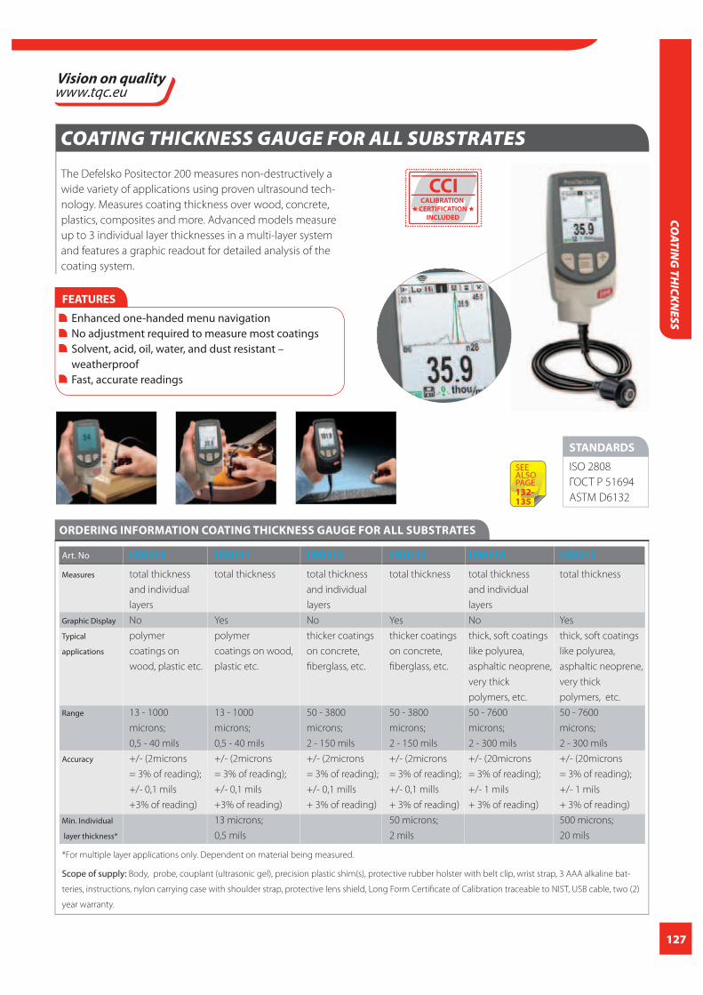
127
COATIN
G TH
ICKNESS
COATING THICKNESS GAUGE FOR ALL SUBSTRATES
The Defelsko Positector 200 measures non-destructively a
wide variety of applications using proven ultrasound tech-
nology. Measures coating thickness over wood, concrete,
plastics, composites and more. Advanced models measure
up to 3 individual layer thicknesses in a multi-layer system
and features a graphic readout for detailed analysis of the
coating system.
STANDARDS
ISO 2808
ГОСТ Р 51694
ASTM D6132
FEATURES
Enhanced one-handed menu navigation No adjustment required to measure most coatings Solvent, acid, oil, water, and dust resistant – weatherproof Fast, accurate readings
ORDERING INFORMATION COATING THICKNESS GAUGE FOR ALL SUBSTRATES
Art. No LD0210 LD0211 LD0212 LD0213 LD0214 LD0215
Measures total thickness total thickness total thickness total thickness total thickness total thickness
and individual and individual and individual
layers layers layers
Graphic Display No Yes No Yes No Yes
Typical polymer polymer thicker coatings thicker coatings thick, soft coatings thick, soft coatings
applications coatings on coatings on wood, on concrete, on concrete, like polyurea, like polyurea,
wood, plastic etc. plastic etc. fi berglass, etc. fi berglass, etc. asphaltic neoprene, asphaltic neoprene,
very thick very thick
polymers, etc. polymers, etc.
Range 13 - 1000 13 - 1000 50 - 3800 50 - 3800 50 - 7600 50 - 7600
microns; microns; microns; microns; microns; microns;
0,5 - 40 mils 0,5 - 40 mils 2 - 150 mils 2 - 150 mils 2 - 300 mils 2 - 300 mils
Accuracy +/- (2microns +/- (2microns +/- (2microns +/- (2microns +/- (20microns +/- (20microns
= 3% of reading); = 3% of reading); = 3% of reading); = 3% of reading); = 3% of reading); = 3% of reading);
+/- 0,1 mils +/- 0,1 mils +/- 0,1 mills +/- 0,1 mills +/- 1 mils +/- 1 mils
+3% of reading) +3% of reading) + 3% of reading) + 3% of reading) + 3% of reading) + 3% of reading)
Min. Individual 13 microns; 50 microns; 500 microns;
layer thickness* 0,5 mils 2 mils 20 mils
*For multiple layer applications only. Dependent on material being measured.
Scope of supply: Body, probe, couplant (ultrasonic gel), precision plastic shim(s), protective rubber holster with belt clip, wrist strap, 3 AAA alkaline bat-
teries, instructions, nylon carrying case with shoulder strap, protective lens shield, Long Form Certifi cate of Calibration traceable to NIST, USB cable, two (2)
year warranty.
CCICALIBRATION
CERTIFICATION
INCLUDED
SEE ALSOPAGE132-135

128
COAT
ING
TH
ICKN
ESS
POWDERTAG THICKNESS ANALYSING GAUGE
PowderTAG measures powder coating thickness before
and after cure, non-contact and non-destructive.
A sophisticated combination of specifi c powder-,
infrared- and photo-thermal techniques measures the
thickness of powder coatings in pre-cured and cured
status, precize and reproducible.
Save on powder consumption!
Save on rework and reject!
Improve effi ciency!
Improve quality!
PowderTAG is a non-contact production tool, developed
for use at the paint-line.
The instrument is equipped with a clear full colour TFT
display and substantial memory capacity for storage of Ideal
Finish Analysis measurements and settings. PowderTag com-
municates with IFA, TQC’s powerful analysis and reporting
software.
NEW
Expected early 2015
FEATURES
Easy to operate. Just point the probe at the surface at the right distance (LED-Pointers will indicate the correct distance / location) and press the “measure” button. Measures any form, shape and dimension. Including wire frames or edges. Large measuring range combined with a very high accuracy level.
aluminium and MDF Large measuring range. 150 μm and over.* Extremely accurate. Accuracy ± 2 μm or better*. Suitable for uncured and cured powder coatings.
* Depending on coating type and substrate.
IDEAL FINISH ANALYSIS
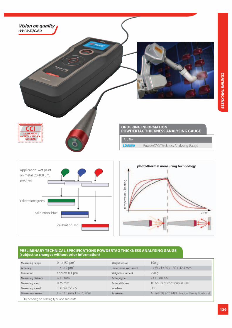
129
COATIN
G TH
ICKNESS
ORDERING INFORMATION POWDERTAG THICKNESS ANALYSING GAUGE
Art. No
LD5850 PowderTAG Thickness Analysing Gauge
PRELIMINARY TECHNICAL SPECIFICATIONS POWDERTAG THICKNESS ANALYSING GAUGE(subject to changes without prior information)
Measuring Range 0 - >150 μm*
Accuracy +/- < 2 μm*
Resolution approx. 0,1 μm
Measuring distance ≈ 15 mm
Measuring spot 0,25 mm
Measuring speed 100 ms tot 2 S
Dimensions sensor L = 110 mm, D = 25 mm
Weight sensor 150 g
Dimensions instrument L x W x H: 80 x 180 x 42,4 mm
Weight instrument 750 g
Battery type 2X Li-Ion AA
Battery lifetime 10 hours of continuous use
Interface USB
Substrates All metals and MDF (Medium Density Fibreboard)
* Depending on coating type and substrate.
tem
pe
ratu
re /
he
ati
ng
time
calibration: green
calibration: blue
calibration: red
Application: wet paint
on metal, 20-100 μm,
predried
photothermal measuring technology
CCICALIBRATION
CERTIFICATION
INCLUDED

130
FEATURES
Hi Contrast reversible color LCD
names with onscreen QWERTY keyboard
net, downloads software updates and connects with mobile devices for expanded functionality
PosiTector PC accepts all PosiTector probes easily converting from measuring uncured powder to cured dry fi lm thickness, surface profi le, and more. PosiSoft solutions for viewing analyzing and reporting data include PosiSoft USB, PosiSoft.net, PosiSoft 3.0 Desktop software and PosiSoft Mobile
POWDER COATING METER POWDERCHECKER XP
The TQC PowderChecker XP optimizes the powder ap-
plication by measuring the output of the cabin. The TQC
PowderChecker XP measures uncured powder coatings
using ultrasonic technology to automatically calculate a
predicted cured thickness. This is sent by Bluetooth® to the
recorder, where the value is shown in the large display. Tak-
ing a measurement is fast and accurate (3%) in the range of
30 to 110 microns.
Using the TQC
PowderChecker XP
saves on powder and
reduces loss of
products. For most
powders no calibration
adjustment is required.
STANDARDS
ISO 2808
ASTM D7378
ГОСТ Р 51694
TECHNICAL SPECIFICATIONS POWDER COATING METER POWDERCHECKER XP
Range 20-110 μm / 0,8-4,3 mils
Resolution 1 μm / 0.05 mils
Accuracy +/- 5 μm / +/- 0,2 mils
Measurement Time 2 -5 seconds
Measurement Distance 18 mm / 0,75 inch
to Powder
Measurement Area 2 mm / 0,08 inch
Material Plastic
Size Base Unit 146x64x31 mm / 5,75x2,5x1,2 inch
Weight Base Unit 165 g / 5,8 oz. without batteries
Probe Size 222 x Ø50 mm / 8,75x Ø2,0 inch
Weight Probe 272 g / 9,6 oz. without batteries
ORDERING INFORMATION POWDER COATINGMETER POWDERCHECKER X
Art. No
LD5820 TQC PowderChecker XP
Scope of supply: base unit and probe, protective rubber holster with
belt loop and magnetic mount, probe fi xture, 3 AAA batteries (base
unit), 3 AA batteries (probe), instructions, instructional video,
replacement probe screen, USB cable, carabiner and wrist strap, durable
carrying case, two (2) year warranty.
COAT
ING
TH
ICKN
ESS
CCICALIBRATION
CERTIFICATION
INCLUDED
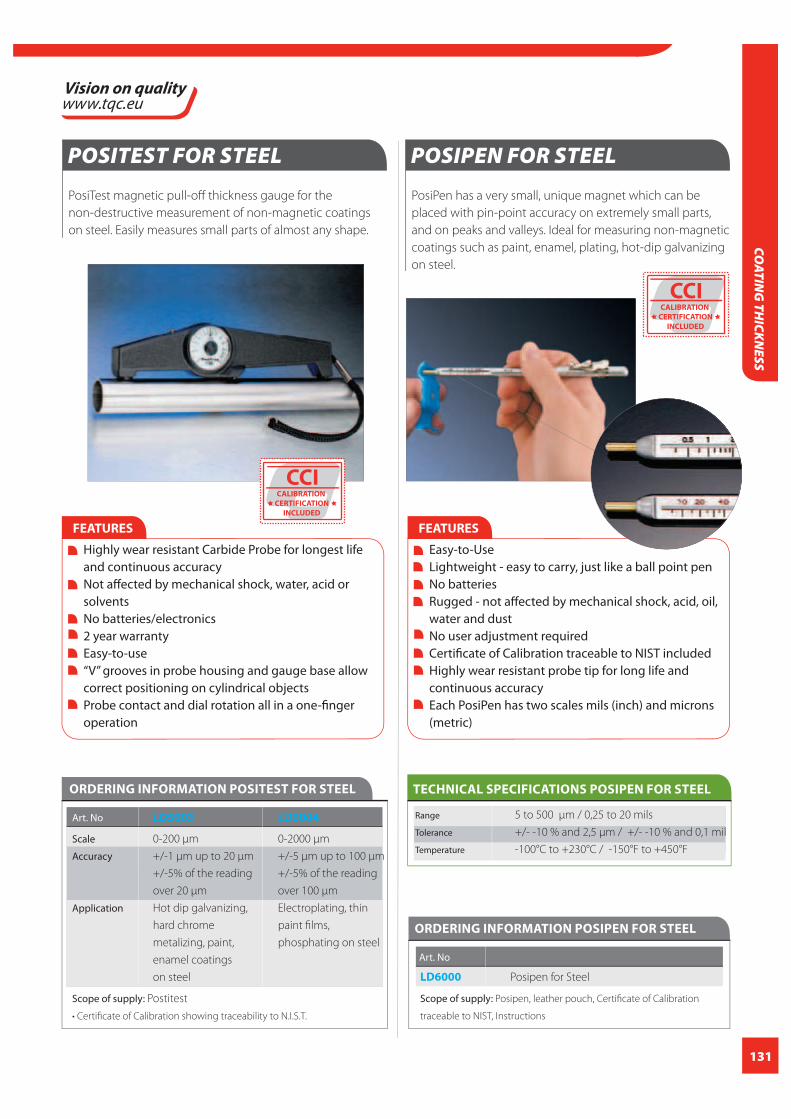
131
COATIN
G TH
ICKNESS
POSITEST FOR STEEL
PosiTest magnetic pull-off thickness gauge for the
non-destructive measurement of non-magnetic coatings
on steel. Easily measures small parts of almost any shape.
FEATURES
Highly wear resistant Carbide Probe for longest life and continuous accuracy Not aff ected by mechanical shock, water, acid or solvents No batteries/electronics 2 year warranty Easy-to-use “V” grooves in probe housing and gauge base allow correct positioning on cylindrical objects Probe contact and dial rotation all in a one-fi nger operation
ORDERING INFORMATION POSITEST FOR STEEL
Art. No LD5003 LD5004
Scale 0-200 μm 0-2000 μm
Accuracy +/-1 μm up to 20 μm +/-5 μm up to 100 μm
+/-5% of the reading +/-5% of the reading
over 20 μm over 100 μm
Application Hot dip galvanizing, Electroplating, thin
hard chrome paint fi lms,
metalizing, paint, phosphating on steel
enamel coatings
on steel
Scope of supply: Postitest
POSIPEN FOR STEEL
PosiPen has a very small, unique magnet which can be
placed with pin-point accuracy on extremely small parts,
and on peaks and valleys. Ideal for measuring non-magnetic
coatings such as paint, enamel, plating, hot-dip galvanizing
on steel.
FEATURES
Easy-to-Use Lightweight - easy to carry, just like a ball point pen No batteries Rugged - not aff ected by mechanical shock, acid, oil, water and dust No user adjustment required Certifi cate of Calibration traceable to NIST included Highly wear resistant probe tip for long life and continuous accuracy Each PosiPen has two scales mils (inch) and microns (metric)
ORDERING INFORMATION POSIPEN FOR STEEL
Art. No
LD6000 Posipen for Steel
Scope of supply: Posipen, leather pouch, Certifi cate of Calibration
traceable to NIST, Instructions
Range 5 to 500 μm / 0,25 to 20 mils
Tolerance +/- -10 % and 2,5 μm / +/- -10 % and 0,1 mil
Temperature -100°C to +230°C / -150°F to +450°F
TECHNICAL SPECIFICATIONS POSIPEN FOR STEEL
CCICALIBRATION
CERTIFICATION
INCLUDED
CCICALIBRATION
CERTIFICATION
INCLUDED
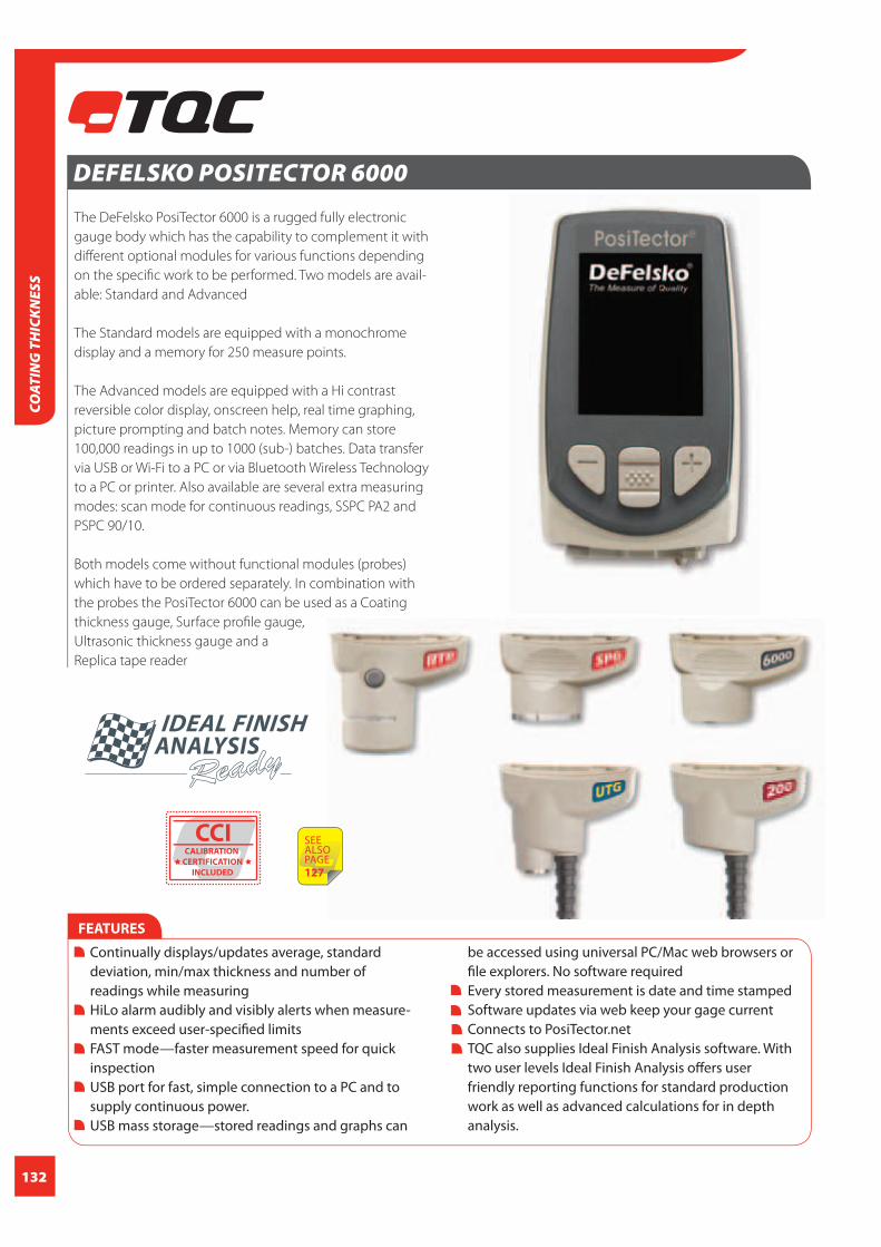
132
DEFELSKO POSITECTOR 6000
The DeFelsko PosiTector 6000 is a rugged fully electronic
gauge body which has the capability to complement it with
diff erent optional modules for various functions depending
on the specifi c work to be performed. Two models are avail-
able: Standard and Advanced
The Standard models are equipped with a monochrome
display and a memory for 250 measure points.
The Advanced models are equipped with a Hi contrast
reversible color display, onscreen help, real time graphing,
picture prompting and batch notes. Memory can store
100,000 readings in up to 1000 (sub-) batches. Data transfer
via USB or Wi-Fi to a PC or via Bluetooth Wireless Technology
to a PC or printer. Also available are several extra measuring
modes: scan mode for continuous readings, SSPC PA2 and
PSPC 90/10.
Both models come without functional modules (probes)
which have to be ordered separately. In combination with
the probes the PosiTector 6000 can be used as a Coating
thickness gauge, Surface profi le gauge,
Ultrasonic thickness gauge and a
Replica tape reader
FEATURES
Continually displays/updates average, standard deviation, min/max thickness and number of readings while measuring HiLo alarm audibly and visibly alerts when measure- ments exceed user-specifi ed limits FAST mode—faster measurement speed for quick inspection USB port for fast, simple connection to a PC and to supply continuous power. USB mass storage—stored readings and graphs can
be accessed using universal PC/Mac web browsers or fi le explorers. No software required Every stored measurement is date and time stamped Software updates via web keep your gage current Connects to PosiTector.net TQC also supplies Ideal Finish Analysis software. With two user levels Ideal Finish Analysis off ers user friendly reporting functions for standard production work as well as advanced calculations for in depth analysis.
COAT
ING
TH
ICKN
ESS
IDEAL FINISH ANALYSIS
CCICALIBRATION
CERTIFICATION
INCLUDED
SEE ALSOPAGE127

133
TECHNICAL SPECIFICATIONS DEFELSKO POSITECTOR 6000
Replica Tape Reader RTRMeasuring Range 20 – 115 um / 0.8 – 4.5 mils
Accuracy +/- 5 um / +/- 0.2 mils
Resolution 1 um /0.1 mil
Anvil Pressure 110 grams-force / 1.1 Newtons
Anvil Size Ø 6.25 mm / Ø 0.25 inch
Temperature Range 0° to 40°C / +32° to +104°F
PosiTector 6000 bodyGage Size 152 x 61 x 28 mm / 6” x 2.4” x 1.1”
Weight (without batteries) 140 g / 4.9 oz
Power “Alkaline”, “Lithium” or “NiMH” (N ickel-metal
hydride rechargeable)
Languages English, French, German, Spanish, Chinese,
Japanese, Portugese, Italian, Norwegian
Russian, Czech, Polish, Korean, Dutch
Surface Profi le SPG Range 0 – 500 μm (0 – 20 mils)
Accuracy +/- (5 μm + 5%) of reading, +/-
(0.2 mils + 5%) of reading
Resolution 1 μm (0.1 mils)
Probe tip 60° angle with a 50μm radius tip
Measurement speed >40 readings per minute
Weight 140 g (4.9 oz.) without batteries
Dimensions 137x61x28 mm (5.4” x 2.4” x 1.1”)
Ultrasonic Thickness Probes Corrosion probe Multi Echo probe
Measurement range 1.0 to 125.0 mm / 0.040” to 5.000” 2.5 to 60.0 mm / 0.100” to 2.500”
for carbon steel and depends on surface conditions
Measurement Rate – Normal 6 readings/sec. 4 readings/sec.
Measurement Rate – Scan 20 readings/sec. 4 readings/sec.
Resolution +/-0.01mm / 0.001” +/-0.01mm / 0.001”
Accuracy +/-0.03 mm / 0.001” +/-0.03 mm / 0.001”
Probe type 5 MHz Dual Element 5 MHz Contact
Mode Single Echo Multi Echo
Scope of supply: Instrument body, protective rubber holster with belt clip, wrist strap, 3 AAA alkaline batteries, instruction manual, protective lens
shield, convenient carrying case, USB cable, PosiSoft.net account, Long Form Certifi cate of Calibration traceable to NIST and two (2) year warranty
STANDARDS
Thickness ISO 2808, ISO 2360, ГОСТ Р 51694, BS 5411, BS
3900 – C5, DIN 50981, DIN 50984, ASTM B 499,
ASTM D 1400
SPG ASTM D4417-B, AS 3894.5-C
(with optional 30° tip angle),
U.S. Navy NSI 009-32, SANS 5772 and others.
RTR ASTM D4417, ISO 8503-5, NACE RP287,
SSPC-PA 17, SP6, SP10, SP11-87T and others
UTG ASTM E797
COATIN
G TH
ICKNESS
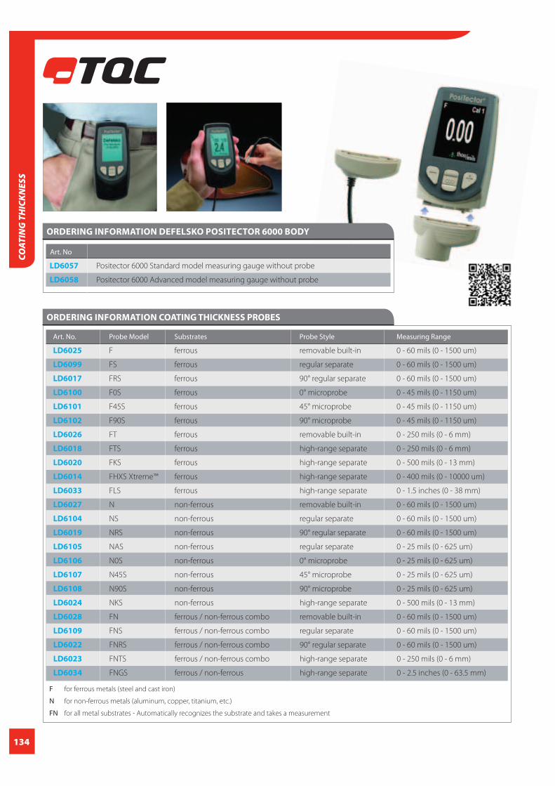
134
Art. No
LD6057 Positector 6000 Standard model measuring gauge without probe
LD6058 Positector 6000 Advanced model measuring gauge without probe
ORDERING INFORMATION DEFELSKO POSITECTOR 6000 BODY
ORDERING INFORMATION COATING THICKNESS PROBES
Art. No. Probe Model Substrates Probe Style Measuring Range
LD6025 F ferrous removable built-in 0 - 60 mils (0 - 1500 um)
LD6099 FS ferrous regular separate 0 - 60 mils (0 - 1500 um)
LD6017 FRS ferrous 90° regular separate 0 - 60 mils (0 - 1500 um)
LD6100 F0S ferrous 0° microprobe 0 - 45 mils (0 - 1150 um)
LD6101 F45S ferrous 45° microprobe 0 - 45 mils (0 - 1150 um)
LD6102 F90S ferrous 90° microprobe 0 - 45 mils (0 - 1150 um)
LD6026 FT ferrous removable built-in 0 - 250 mils (0 - 6 mm)
LD6018 FTS ferrous high-range separate 0 - 250 mils (0 - 6 mm)
LD6020 FKS ferrous high-range separate 0 - 500 mils (0 - 13 mm)
LD6014 FHXS Xtreme™ ferrous high-range separate 0 - 400 mils (0 - 10000 um)
LD6033 FLS ferrous high-range separate 0 - 1.5 inches (0 - 38 mm)
LD6027 N non-ferrous removable built-in 0 - 60 mils (0 - 1500 um)
LD6104 NS non-ferrous regular separate 0 - 60 mils (0 - 1500 um)
LD6019 NRS non-ferrous 90° regular separate 0 - 60 mils (0 - 1500 um)
LD6105 NAS non-ferrous regular separate 0 - 25 mils (0 - 625 um)
LD6106 N0S non-ferrous 0° microprobe 0 - 25 mils (0 - 625 um)
LD6107 N45S non-ferrous 45° microprobe 0 - 25 mils (0 - 625 um)
LD6108 N90S non-ferrous 90° microprobe 0 - 25 mils (0 - 625 um)
LD6024 NKS non-ferrous high-range separate 0 - 500 mils (0 - 13 mm)
LD6028 FN ferrous / non-ferrous combo removable built-in 0 - 60 mils (0 - 1500 um)
LD6109 FNS ferrous / non-ferrous combo regular separate 0 - 60 mils (0 - 1500 um)
LD6022 FNRS ferrous / non-ferrous combo 90° regular separate 0 - 60 mils (0 - 1500 um)
LD6023 FNTS ferrous / non-ferrous combo high-range separate 0 - 250 mils (0 - 6 mm)
LD6034 FNGS ferrous / non-ferrous high-range separate 0 - 2.5 inches (0 - 63.5 mm)
F for ferrous metals (steel and cast iron)
N for non-ferrous metals (aluminum, copper, titanium, etc.)
FN for all metal substrates - Automatically recognizes the substrate and takes a measurement
COAT
ING
TH
ICKN
ESS

135
Art. No. Probe Model Substrates Probe Style Measuring Accuracy
Range
LD6029 SPG 60 (Roughness) Tungsten 0 - 20 mils +/- (5 μm + 5%)
Carbide tip 60° (0 - 500 um) +/- (0.2 mil + 5%)
LD6032 SPG 30 (Roughness) Tungsten 0 - 20 mils +/- (5 μm + 5%)
Carbide tip 30° (0 - 500 um) +/- (0.2 mil + 5%)
ORDERING INFORMATION SURFACE PROFILE PROBE
ORDERING INFORMATION ULTRASONIC THICKNESS PROBE
EArt. No. Probe Model Substrates
LD7109 UTG C Corrosion Probe Uncoated Steel, Cast Iron, SS, Aluminium, PVC, Plexiglas,
Polystyrene
LD7110 UTG M Multiple Echo Probe True paint
ORDERING INFORMATION REPLICA TAPE PROBE
EArt. No. Probe Model Substrates Anvil Pressure Measuring range Accuracy
LD5432 RTR sensor (Roughness) 110 grams-force 20 to 115 μm + 5 μm
(1.1 N) (0.8 to 4.5 mils) (+ 0.2 mils)
COATIN
G TH
ICKNESS

136
MATERIAL THICKNESSMaterial thickness is often confused with coating- or layer thickness. With layer thickness we speak about one or multiple
layers attached to a substrate. With material thickness we speak about the actual thickness of the substrate itself.
Sometimes the material thickness can be measured easily using mechanical measuring tools like callipers or other simple
means. However in certain situations the accessibility of the measuring spot is not suitable to use mechanical tools. Think
about a wall of a ship or vessel or the mid section of large (steel) plates. In these situations ultrasonic measuring devices or
wall thickness gauges are used to accurately determine material thickness.
Ultrasonic gauges
Ultrasonic gauges send out an ultrasound pulse through
the material from one side only.
Converting the time of fl ight of the pulse of sound energy
refl ecting back of the opposite surface results in the mate-
rial thickness in millimetres or fractions of an inch.
The system of measuring thickness by ultrasound pulses
works on a variety of materials:
example metal or plastics. Materials with lower densities
like wood or concrete are hard- or impossible to measure
with these instruments.
Plastic or epoxy can be measured without any problems
and so can glass. However glass fi bre reinforced epoxies
are impos sible to measure since these are two diff erent
materials with diff erent densities.
a very good contact. Very rough surface may cause
problems in that respect. The aid of couplant gel is a
must in most application.
Most ultrasonic gauges allow the user to set the ultra
sound speed of the instrument. The ultrasound speed
of many materials is known and can be retrieved from
the table hereunder.
Material / Sound velocity (M/S)
Aluminum 6260 Steel 5900
Gold 3240 Glycerin 1920
Copper 4700 Brass 4640
Polypropylene 2730 Silver 3600
Water at 20°C 1480 Water-glass 2350
Zinc 4170 Tin 3230
When the ultrasound speed of the material is unknown
and it meets the earlier mentioned requirements an ultra-
sonic wall thickness gauge can be calibrated in a simple
way. Just take a piece of the material to be measured with
a known thickness. Place the instrument on the mate-
rial and adjust the thickness reading to meet the actual
thickness of the sample. The instrument will automatically
calculate the corresponding ultrasound speed of the
material so that speed setting can be used for future mea-
surements on the same material.
MAT
ERIA
L TH
ICKN
ESS

137
ULTRASONIC WALL THICKNESS GAUGE
Ultrasonic thickness gauge specifically designed to measure
the thickness of metallic and non-metallic materials e.g.
aluminium, titanium, plastics, ceramics, glass and plastics. It
can also be used to monitor all types of pipes and pressure
vessels for loss of thickness due to corrosion or erosion. The
gauge is easy to use and will give accurate readings to an
accuracy of 1%. This unit is not suitable for cast iron due to
its big crystalloid composition.
Available in 2 models, Basic and Pro. The Pro version allows
you to store data and perform a sound velocity measure-
ment (with a known material thickness), this model is also
supplied with an extra probe (5.0MHz). The Basic version has
10 preset sound velocities and does not have the possibility
to store data.FEATURES
Large LCD screen Battery indicator Automatic power shut down Coupling indicator Small in size; light in weight; easy to use Simple calibration procedure 10 preset sound velocities (model LD7015) 10 data storage units (model LD7016) Sound velocity measurement (with a known thickness of material) (model LD7016)
Measuring method Ultrasonic pulse echo
Display: LCD
Resolution: 0.1mm
Accuracy +/- (1%H + 0.1) mm
(H denotes the measured thickness)
Operation temperature 0 ºC ~ 40 ºC / 32 ~ 104 °F
Power supply 3x AAA alkaline batteries (total 5V)
Size 70x135x38 mm / 2,76x5,31x1,5 inch
TECHNICAL SPECIFICATIONS ULTRASONIC WALL THICKNESS GAUGE
ORDERING INFORMATION ULTRASONIC WALL THICKNESS GAUGE
Art. No LD7015 LD7016*
Measuring frequency 5MHz 5MHz / 2.5MHz
Measuring range 1,20 - 220 mm (steel); 1.20 - 220 mm / 0,05x8,66 inch (steel); Actual range
(deviation possible with use of other materials) varies with the type of material measured
Measuring tubes 20x3 mm / 0,79x0,12 inch (steel)
Accuracy +/- (1%H + 0.1) mm +/- (1%H + 0.1) mm, H denotes the measured thickness
Sound velocity 10 presets 1000 - 9999 m/s.
Data storage - 10 units
* Measuring sound velocity with a given thickness: Measuring range: 1000 to 9999 m/s. When the given thickness is over 20mm, the accuracy is +/-5%;
when the given thickness is less than 20mm, the accuracy is +/- 1 mm/H*100%
Scope of supply:
LD7015 TQC Ultrasonic Thickness Gauge Basic, Ultrasonic gel 60 ml / 2,03 oz, Probe 10 mm / 0,39 inch - 5.0 MHz, Calibration block, Manual
LD7016 TQC Ultrasonic Thickness Gauge Pro, Ultrasonic gel 60ml / 2,03 oz, Probe 10 mm / 0,39 inch - 5.0 MHz, Probe 10 mm / 0,39 inch –
2.5 MHz , Calibration block, Manual
ACCESSORIES / SPARES
LD7025 TQC ultrasonic gel 50ml / 1,69 oz LD7030 TQC ultrasonic gel 250ml / 8,45 oz
STANDARDS ASTM E797
MATERIA
L THICKN
ESS

138
POROSITY Coatings applied can have irregularities due to diff erent circumstances. Surface uncleanness, paint diff erences
and dust or air bubbles enclosed can cause pinholes, thin spots, cracks etc. To prevent an early breakdown of
the coating system causing corrosion underneath, tests has to be made to fi nd the weak spots and action can
be taken before problems occur over time. For these kind of tests High Voltage Holiday Detectors provide an
accurate way for locating faults in non-conductive coatings and linings and detection of pinholes, fl aws, inclu-
sions, thin spots and bubbles in a coating.
High voltage testing of coatings
A High Voltage Holiday Detector is specifi cally designed to revolutionize high voltage DC testing of coatings,
making it safer, easier and more reliable than previously possible. The gauge can only be used to fi nd fl aws in
coatings whose substrate is made from a conductive material (metal, concrete etc.). The units have variable
sensitivity and are fi tted with audible and visual fault alarms.
The high voltage technique can be used to test coatings up to 36 mm thick. This method is ideal for inspecting
paint on pipelines, tank bottoms and other protective coatings. Coatings on concrete can also be tested using
this method.
The instrument has a lot of unique features. A current limiting to avoid coating damage and a safety hand grip
without sensitive electronics. Extended ribbing on the handle provides an eff ective barrier between the high
voltage and the user. Accurate sensitivity adjustment allows use on metalized or slightly damp coatings.
As most instruments are portable there is no need to swap power supplies or change probes to change
voltage. The Detectors have clip-on battery packs that can be charged separately. Applied voltage and battery
condition are continuously shown on the Liquid Crystal Display.
Nace regulations
To perform tests without damaging the coating Test Voltages need to be limited and set according to
regulations according to NACE.
a. The Nace RP-0490-2001 calculates the voltage in the formula: Voltage in kV = square root of the layer
thickness in microns * 125. For example, when a coating thickness of 400μm: Root 400 = 20 * 125 = 2500V
(2.5 kV). NB. The rule is a directive and cannot be seen as an absolute value.
b. The Nace RP-0274-98 calculates the voltage in the formula: Voltage in kV = square root of the layer
thickness in microns * 250. For example, when a coating thickness of 3200μm:
Root 3200 = 56.5 * 250 = 14140V (14.1 kV). NB. The rule is a directive and cannot be seen as an absolute
value.
Low voltage testing of coatings
In those cases where high voltage testing is not desirable or possible due to thin coating thicknesses up to 500
micron, another test system should be used. For these a Low Voltage Pinhole Detector is used with selectable
voltages of 9, 67.5 and 90 volts. Depending on the coating thickness under test use 9 volt for coatings up to 300
micron, 67.5 volt for coatings up to 400 micron and 90 volt for coatings until 500 micron. The system consists
of a battery operated instrument with earth lead and a wet sponge as electrode. By moving the slightly wetted
sponge over the test area moisture will pass the pinhole due to capillary absorption making contact with the
base substrate causing an alarm to indicate a pinhole.
PORO
SITY

139
PORO
SITY
LOW VOLTAGE PINHOLE DETECTOR
Low voltage pinhole detector to detect defects on several
types of coatings on ferrous substrates by using the wet
sponge technique.
FEATURES
- Color Display with battery indicator and menu based user interface Intuitive single button controls Visual, audible and tactile feedback* Return cable connectivity detection* Smart power saving features (screen dimming, standby, auto power-off ) Detected pinhole counter Automated self-diagnostics
* Depending on model
TECHNICAL SPECIFICATIONS LOW VOLTAGE PINHOLE DETECTOR
Sensitivity 100 kΩ +/-5% (all voltages)
Maximum coat 500μm / 20mils
Batteries 3x AA Penlight (Alkaline / NiCd / NiMH)
Battery life Up to 150 hours (depending on battery
type and operating conditions)
Dimensions 237x47x47 mm / 9,33x1,85x1,85 inch
(without wand)
Weight ~350 gr (without wand)
~600 gr (with wand)
STANDARDS
ISO 8289-A
ISO 14654
BS 7793
ASTM D 5162-A
JIS K 6766
TM0384
ORDERING INFORMATION LOW VOLTAGE PINHOLE DETECTOR
Art. No LD8100 LD8105
Voltage 9V, 90V 9V, 24V, 67,5V, 90V
Accuracy 9V +/- 2% +/- 2%
24V - +/- 2%
67,5V - +/- 2%
90V +/- 5% +/- 5%
Scope of supply: TQC low voltage pinhole detector , Handle with
sponge, Earth lead with clip, Calibration certifi cate
CCICALIBRATION
CERTIFICATION
INCLUDED
Inspector’s accessory-kit
coming soon
SEE ALSOPAGE196

140
PORO
SITY
FEATURES
Lightweight with ABS case Momentary on switch allows auto shut-off Digital display of applied voltage with integral battery condition indicator Regulated DC voltage Voltage ranges of 0-15Kv or 0-30Kv, fully adjustable Clip-on battery pack Constant test current Sensitivity control Overcharge protection Single power supply Earphones for noisy environments Optional on/off switch in handle
TECHNICAL SPECIFICATIONS HIGH VOLTAGE HOLIDAY DETECTOR
DC15 DC30Unit Weight 2.2 Kg. 2.2 Kg.
Packed weight 6.0 Kg. 6.0 Kg.
Display LCD 3¾ digits LCD 3¾ digits
Voltage 0 to 15kv 0 to 30kv
Resolution 10v 10v
Short circuit Test current 0.5mA max
Power supply Gel cell 3Ah slide-off
Dimensions 260 x 160 x 70 mm
Alarm Audible and visual
Probe handle 2m high-voltage silicon-rubber lead
Battery condition LCD Display
ORDERING INFORMATION HIGH VOLTAGE HOLIDAY DETECTOR
Art. No
LD8503 TQC High Voltage Holiday Detector 30kV
LD8504 TQC High Voltage Holiday Detector 15kV
HIGH VOLTAGE HOLIDAY DETECTOR
The TQC High Voltage Holiday Detector or porosity test
provides accurate detection of pinholes, fl aws, inclusions,
thin spots and bubbles in a coating. The gauge has been
specifi cally designed to revolutionise high voltage DC
testing of coatings, making it safer, easier and more reli-
able than previously possible.
The high voltage technique can be used to test coatings
up to 36 mm thick. This method is ideal for inspecting
paint on pipelines, tankbottoms and other protective
coatings. Coatings on concrete can also be tested using
this method.
The instrument has a lot of unique features. A current
limiting to avoid coating damage, , and a safety hand grip
without sensitive electronics. Extended ribbing on the
handle provides an eff ective barrier between the high
voltage and the user. Accurate sensitivity adjustment al-
lows use on metallised or slightly damp coatings.Controls1 LCD display (including battery condition indicator)
2 Voltage control (10 turn)
3 Visual alarm indicates when fault is found
4 On switch
5 Off /test switch
6 Sensitivity control for the alarm
7 Audible alarm when fault is found
8 High Voltage probe connector
9 Fuse (1.6A slow blow) 5 x 20mm
10 Earth connection point
11 Charge connector - alows operation while charging is
in progress
12 Clip-on battery pack
13 Earphone (connected on opposite side)
8
9
10
11
7
13
12
12
6
3
4
5CCI
CALIBRATION
CERTIFICATION
INCLUDED
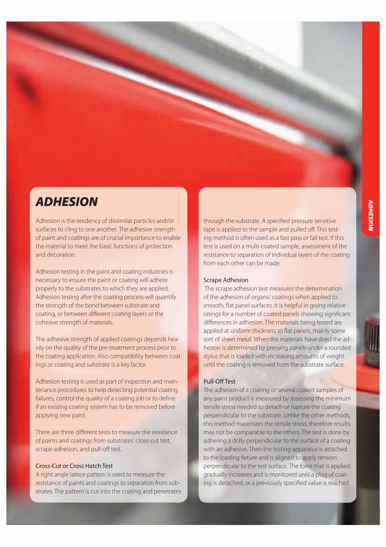
141
PORO
SITY
ADHESION Adhesion is the tendency of dissimilar particles and/or
surfaces to cling to one another. The adhesive strength
of paint and coatings are of crucial importance to enable
the material to meet the basic functions of protection
and decoration.
Adhesion testing in the paint and coating industries is
necessary to ensure the paint or coating will adhere
properly to the substrates to which they are applied.
Adhesion testing after the coating process will quantify
the strength of the bond between substrate and
coating, or between diff erent coating layers or the
cohesive strength of materials.
The adhesive strength of applied coatings depends hea-
vily on the quality of the pre-treatment process prior to
the coating application. Also compatibility between coat-
ings or coating and substrate is a key factor.
Adhesion testing is used as part of inspection and main-
tenance procedures to help detecting potential coating
failures, control the quality of a coating job or to defi ne
if an existing coating system has to be removed before
applying new paint.
There are three diff erent tests to measure the resistance
of paints and coatings from substrates: cross-cut test,
scrape adhesion, and pull-off test.
Cross-Cut or Cross Hatch TestA right angle lattice pattern is used to measure the
resistance of paints and coatings to separation from sub-
strates. The pattern is cut into the coating and penetrates
through the substrate. A specifi ed pressure sensitive
tape is applied to the sample and pulled off . This test-
ing method is often used as a fast pass or fail test. If this
test is used on a multi-coated sample, assessment of the
resistance to separation of individual layers of the coating
from each other can be made.
Scrape Adhesion The scrape adhesion test measures the determination
of the adhesion of organic coatings when applied to
smooth, fl at panel surfaces. It is helpful in giving relative
ratings for a number of coated panels showing signifi cant
diff erences in adhesion. The materials being tested are
applied at uniform thickness to fl at panels, mainly some
sort of sheet metal. When the materials have dried the ad-
hesion is determined by pressing panels under a rounded
stylus that is loaded with increasing amounts of weight
until the coating is removed from the substrate surface.
Pull-Off TestThe adhesion of a coating or several coated samples of
any paint product is measured by assessing the minimum
tensile stress needed to detach or rupture the coating
perpendicular to the substrate. Unlike the other methods,
this method maximizes the tensile stress, therefore results
may not be comparable to the others. The test is done by
adhering a dolly perpendicular to the surface of a coating
with an adhesive. Then the testing apparatus is attached
to the loading fi xture and is aligned to apply tension
perpendicular to the test surface. The force that is applied
gradually increases and is monitored until a plug of coat-
ing is detached, or a previously specifi ed value is reached.
AD
HESIO
N

142
TESTER POSITEST AT-A (AT)
The new PosiTest AT-A Automatic Adhesion Tester measures
adhesion of coatings applied on metal, wood, concrete and
similar substrates.The system is equipped with an electroni-
cally controlled hydraulic pump and measures according to
ISO4624 and ASTM D 4541. The unit is equipped with
a self aligning quick coupling which secures
the dollies tight. Tests are performed by a
simple press on the button. Preset values
like psi or MPa, Dollie size, adhesion force
according international test methods and
storing results into memory. Big display with
Hold function for indication of max. values. Evaluating
measured values on PC is possible by using an adapter
and PC-software.
TECHNICAL SPECIFICATIONS TESTER POSITEST AT-A (AT)
Resolution 1 psi (0.01 MPa)
Accuracy +/- 1% Full Scale
Weight of Kit (with case) 2 lbs / 5.5 kg
Carrying Case Dimensions L – 17 in / 43 cm, W – 13 in / 33 cm,
H – 6 in / 15 cm
Power AT Manual – 2 AAA batteries
Defelsko PosiTest AT-A Adhesiontester, Automatic controlled Defelsko PosiTest AT Adhesiontester, Manually controlled
CCICALIBRATION
CERTIFICATION
INCLUDED
AD
HES
ION
FEATURES
PosiTest Pull-Off Adhesion Tester comes with an environmentally sealed, metal enclosure, heavy duty hydraulic pump and a hi-grade industrial pressure sensor. Both the Manual and Automatic PosiTest AT are built to last and can be used indoors and outdoors in all types of weather. The unit has an unique revolution- ary “self-alignment feature” and pull rate indicator.
ORDERING INFORMATION TESTER POSITEST AT-A (AT)
Art. No
LD9300 Defelsko PosiTest AT-A Adhesiontester, Automatic controlled hydraulic Pull-Off Adhesion Tester with large display.
LD9301 Defelsko PosiTest AT Adhesiontester, Manually controlled hydraulic Pull-Off tester with large display.
ACCESSORIES / SPARES
LD9250 Dolly Drill for Adhesio tests
LD9022 Araldit Epoxy Glue
LD9306 Dollies 20 mm(set of 10 pcs)
LD9307 Dollies 50 mm(set of 4 pcs)
LD9310 Dollies 20 mm (set of 50 pieces)
LD9313 Dollies 10 mm (set of 10 pieces)
LD9314 Dollies 14 mm (set of 10 pieces)
LD9308 Adhesive kit for Defelsko Pull-Off Adhesion Tester

143
AD
HESIO
N
ADHESION TEST PAT HANDY
The TQC Adhesion Test Pat Handy is an easy to use, light-
weight hydraulic adhesion tester that applies an increasing
level of pull off force to a dolly adhered to the surface under
test simply by turning the handle. The adhesion test head
has self adjusting legs, which ensure that the pull off force is
always applied 90º to the coating even on uneven substrate
surfaces. The self adjusting feature results in extremely
accurate and reproducable adhesion test results. The TQC
Adhesion Test Pat Handy weighs only 1250 gram and comes
complete with an A4-size carrying 80 mm height case.
FEATURES
Palm-held, light alloy pull-off tester Case fits easily in the hand luggage (size of an A4 paper and only 80mm thick) DFD® technology for true recording of coating strength All types of coatings on all substrates Any coating thickness Internal and external curved surfaces No test operator bias Precision gauge for accurate measurements Built-in hydraulic safety devices for smooth and drift-proof accuracy
TECHNICAL SPECIFICATIONSADHESION TEST PAT HANDY
Maximum pull force 6.3 kN
Accuracy +/- 1% of full scale
Weight of tester 1.25 kg
Weight complete in case 1.9 kg
Case Dimensions (Wx L xH) 330x 260x80mm
STANDARDS
ISO 4624
EN24624,
ASTM D4541
etc.
ORDERING INFORMATIONADHESION TEST PAT HANDY
Art. No
LD9200 TQC Adhesion Test Pat Handy
Scope of supply: PAThandy™ crank driven hydraulic pull-force pump,
Hydraulic cable, PAT testing head 6.3kN, 5 test elements size Ø20mm,
HSS cutting tool for Ø20mm test element, Carry-case with protective
interior and Calibration Certificate
CCICALIBRATION
CERTIFICATION
INCLUDED

144
FEATURES
Three strong magnets hold the TQC Dolly Drill secure in place The vertical placed circular drill cuts the dolly free from the substrate by means of angled rotating mechanism Accuracy is improved due to the exactly 90° angled cut made by TQC Dolly Drill
TECHNICAL SPECIFICATIONSDOLLY DRILL FOR ADHESION TEST
Material Aluminium
Height 1500 mm / 59,1 inch
Feet diameter approx. 1600 mm / 63 inch with magnets
Drill diameter 2000 mm / 78,7 inch inner
(Drill with inner diameters of 10, 14 and 50 mm / 0,39, 0,55 and 1,97 inch
on request.)
STANDARDS
44 - ASTM D4541
ORDERING INFORMATION DOLLY DRILL FOR ADHESION TEST
Art. No
LD9250 TQC Dolly Drill for Adhesion Test
Scope of supply: TQC Dolly Drill 20mm
ACCESSORIES / SPARES
LD9301 Defelsko PosiTest AT Adhesiontester, Manually controlled hydraulic Pull-Off tester with large display.
LD9300 Defelsko PosiTest AT-A Adhesiontester, Automatic controlled hydraulic Pull-Off Adhesion Tester with large display.
DOLLY DRILL FOR ADHESION TEST
The TQC Dolly Drill is the perfect tool to remove the excess
of glue and cut through the coating around dollies in order
to prepare the dolly for the adhesion test. Fixed positioning
is assured with the three strong magnets, allowing the drill
to remove the coating around the dolly without putting any
force on the dolly. Manually removing the access of glue
and cutting through the coating is a hard job for inspectors
that have to do many tests a day, which results in wrist and
arm pains. The TQC Dolly Drill eases their work considerably,
and increases the accuracy of the pull off adhesion tests
because of a perfect vertical cutting movement down to
the metal.
For the best reproducible results use the Adhesion tester
AT, with the hydraulics and auto positioning feature of the
pull-off head.
AD
HES
ION

145
AD
HESIO
N
CROSS CUT ADHESION TEST BASIC CUTTER
The TQC Cross Cut Adhesion Test Basic Cutter is used to
test the adhesion of dry coats of paint on their substrate by
means of a series of cuts through the coating. Two series of
parallel cuts cross angled to each other to obtain a pattern
of 25 or 100 similar squares. The ruled area is evaluated by
using a table chart after a short treatment with a stiff brush,
or adhesive tape for hard substrates.
The cutting knife of the TQC Cross
Cut Adhesion Test Basic Cutter is
easy to exchange without the use
of extra tools. The self positioning
knife bracket of the TQC Cross Cut
Adhesion Test Basic Cutter ensures
equal pressure on the cutting knife. STANDARDS
ASTM D3359
ISO 2409
ГОСТ 15140
FEATURES
Self-adjusting knife-holder ensures equal pressure on the cutting knife With trailing edge acc. ISO 2409: 2013 Ergonomically shaped handle Easy to change cutting knife, no extra key needed Wide range of knife sizes available for diff erent coating thicknesses and substrates and according to diff erent standards.
TECHNICAL SPECIFICATIONS CROSS CUT ADHESION TEST BASIC CUTTER
Material Vacuum Hardened Stainless Steel,
Aluminium, Rubber
Dimensions 32 x173x42 mm / 1,26x6,81x1,65 inch
Weight 238g / 8,4 oz
TECHNICAL SPECIFICATION CROSS CUT ADHESION TEST BASIC CUTTER
Art. No SP1660 SP1661 SP1662 SP1663 SP1664
Blades 6 6 6 11 11
Teeth distance 1 mm / 0,039 inch 2 mm / 0,079 inch 3 mm / 0,12 inch 1 mm / 0,039 inch 1,5 mm / 0,059 inch
Acc. to ISO 2409 ISO 2409 ISO 2409 ASTM D3359 ASTM D3359
Coating thickness 0-60 μm / 0- 2,4 mils 61-120 μm/ 9.8 mills 121μm to 250μm/ 0-50μm/ 0-2 mills 50-125μm/
on hard substrates 4.7-9.8 mills 2-4.9 mills
Coating thickness - 0-60 μm / 0- 2,4 mils 121 μm to 250 μm / 0-50 μm / 0-2 mills 50-125μm /
on soft substrates 4,7-9,8 mills 2-4,9 mills
Spare knife SP1702 SP1703 SP1704 SP1705 SP1706
Scope of supply: Box with soft grip handle incl. knife holder, hardened steel cutter (type may vary)
ACCESSORIES / SPARES
SP3007 Adhesive tape, single roll, adhesion to steel 4.3 N/cm
SP3010 Adhesive tape, set of 3 rolls, adhesion to steel 4.3 N/cm
SP3020 Adhesive tape, single roll, adhesion to steel 7.6 N/cm
SP1710 Nylon Brush for Cross Cut Adhesion Test
SP9700 Lighted Magnifi er 2.5x
SEE ALSOPAGE120
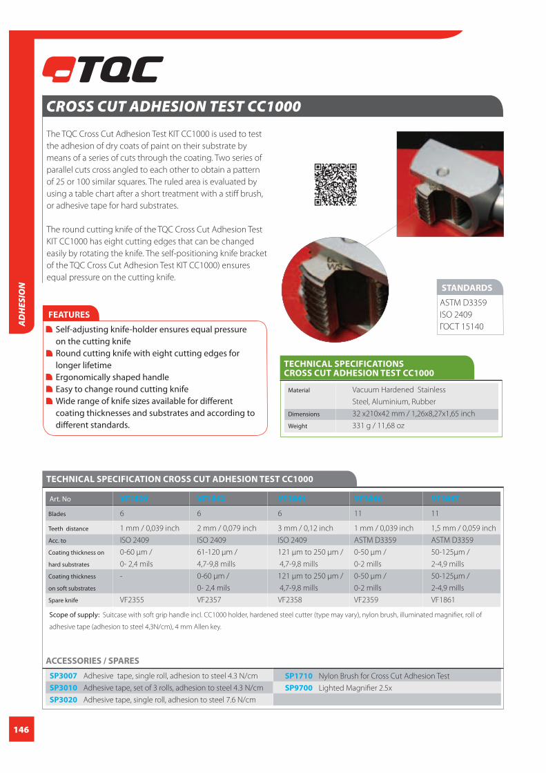
146
CROSS CUT ADHESION TEST CC1000
The TQC Cross Cut Adhesion Test KIT CC1000 is used to test
the adhesion of dry coats of paint on their substrate by
means of a series of cuts through the coating. Two series of
parallel cuts cross angled to each other to obtain a pattern
of 25 or 100 similar squares. The ruled area is evaluated by
using a table chart after a short treatment with a stiff brush,
or adhesive tape for hard substrates.
The round cutting knife of the TQC Cross Cut Adhesion Test
KIT CC1000 has eight cutting edges that can be changed
easily by rotating the knife. The self-positioning knife bracket
of the TQC Cross Cut Adhesion Test KIT CC1000) ensures
equal pressure on the cutting knife.
FEATURES
Self-adjusting knife-holder ensures equal pressure on the cutting knife Round cutting knife with eight cutting edges for longer lifetime Ergonomically shaped handle Easy to change round cutting knife Wide range of knife sizes available for different coating thicknesses and substrates and according to different standards.
STANDARDS
ASTM D3359
ISO 2409
ГОСТ 15140
TECHNICAL SPECIFICATIONS CROSS CUT ADHESION TEST CC1000
Material Vacuum Hardened Stainless
Steel, Aluminium, Rubber
Dimensions 32 x210x42 mm / 1,26x8,27x1,65 inch
Weight 331 g / 11,68 oz
TECHNICAL SPECIFICATION CROSS CUT ADHESION TEST CC1000
Art. No VF1839 VF1842 VF1844 VF1846 VF1847
Blades 6 6 6 11 11
Teeth distance 1 mm / 0,039 inch 2 mm / 0,079 inch 3 mm / 0,12 inch 1 mm / 0,039 inch 1,5 mm / 0,059 inch
Acc. to ISO 2409 ISO 2409 ISO 2409 ASTM D3359 ASTM D3359
Coating thickness on 0-60 μm / 61-120 μm / 121 μm to 250 μm / 0-50 μm / 50-125μm /
hard substrates 0- 2,4 mils 4,7-9,8 mills 4,7-9,8 mills 0-2 mills 2-4,9 mills
Coating thickness - 0-60 μm / 121 μm to 250 μm / 0-50 μm / 50-125μm /
on soft substrates 0- 2,4 mils 4,7-9,8 mills 0-2 mills 2-4,9 mills
Spare knife VF2355 VF2357 VF2358 VF2359 VF1861
Scope of supply: Suitcase with soft grip handle incl. CC1000 holder, hardened steel cutter (type may vary), nylon brush, illuminated magnifier, roll of
adhesive tape (adhesion to steel 4,3N/cm), 4 mm Allen key.
ACCESSORIES / SPARES
SP3007 Adhesive tape, single roll, adhesion to steel 4.3 N/cm
SP3010 Adhesive tape, set of 3 rolls, adhesion to steel 4.3 N/cm
SP3020 Adhesive tape, single roll, adhesion to steel 7.6 N/cm
SP1710 Nylon Brush for Cross Cut Adhesion Test
SP9700 Lighted Magnifier 2.5x
AD
HES
ION

147
CROSS CUT ADHESION TEST CC2000
The TQC CC2000 Cross Cut Adhesion Test KIT is used to test
the adhesion of dry coats of paint on their substrate by
means of a series of cuts through the coating. Two series of
parallel cuts cross angled to each other to obtain a pattern
of 25 or 100 similar squares. The ruled area is evaluated by
using a table chart after a short treatment with a stiff brush,
or adhesive tape for hard substrates.
The cutting knife of the TQC Cross Cut Adhesion Test
CC2000 is easy to exchange without the use of extra tools.
The self-positioning knife bracket of
the TQC Cross Cut Adhesion Test
CC2000 ensures equal
pressure on the cutting knife.
STANDARDS
ASTM D3359
ISO 2409
ГОСТ 15140
FEATURES
Self-adjusting knife-holder ensures equal pressure on the cutting knife With trailing edge acc. ISO 2409: 2013 Ergonomically shaped handle Easy to change cutting knife, no extra key needed Wide range of knife sizes available for different coating thicknesses and substrates and according to different standards.
TECHNICAL SPECIFICATIONS CROSS CUT ADHESION TEST CC2000
Material Vacuum Hardened Stainless Steel,
Aluminium, Rubber
Dimensions 32 x1173x42 mm / 1,26x6,81x1,65 inch
Weight 238 g / 8,4 oz
TECHNICAL SPECIFICATION CROSS CUT ADHESION TEST CC2000
Art. No SP1690 SP1691 SP1692 SP1699 SP1700 SP1693
Blades 6 6 6 11 11 No knife, kit only
Teeth distance 1 mm / 2 mm / 3 mm / 1 mm / 1,5 mm /
0,039 inch 0,079 inch 0,12 inch 0,039 inch 0,059 inch
Acc. to ISO 2409 ISO 2409 ISO 2409 ASTM D3359 ASTM D3359
Coating thickness on 0-60 μm / 61-120 μm / 121 μm to 250 μm / 0-50 μm / 50-125μm /
hard substrates 0- 2,4 mils 4,7-9,8 mills 4,7-9,8 mills 0-2 mills 2-4,9 mills
Coating thickness on - 0-60 μm / 121 μm to 250 μm / 0-50 μm / 50-125μm /
soft substrates 0- 2,4 mils 4,7-9,8 mills 0-2 mills 2-4,9 mills
Spare knife SP1702 SP1703 SP1704 SP1705 SP1706
Scope of supply: Suitcase with soft grip handle incl. CC2000 holder, hardened steel cutter (type may vary), nylon brush, illuminated magnifier, roll of
adhesive tape (adhesion to steel 4,3N/cm)
ACCESSORIES / SPARES
SP3007 Adhesive tape, single roll, adhesion to steel 4.3 N/cm
SP3010 Adhesive tape, set of 3 rolls, adhesion to steel 4.3 N/cm
SP3020 Adhesive tape, single roll, adhesion to steel 7.6 N/cm
SP1710 Nylon Brush for Cross Cut Adhesion Test
SP9700 Lighted Magnifier 2.5x
AD
HESIO
N

148
AD
HES
ION
CROSS CUT ADHESION TEST CC3000
The TQC Cross Cut Adhesion Test KIT CC3000 is used to test
the adhesion of dry coats of paint on their substrate by
means of a series of cuts through the coating. Two series of
parallel cuts cross angled to each other to obtain a pattern
of 25 or 100 similar squares. The ruled area is evaluated by
using a table chart after a short treatment with a stiff brush,
or adhesive tape for hard substrates.
The cutting depth of the TQC Cross Cut Adhesion Test KIT
CC3000 can be adjusted while the cutter is guided by two
ball bearings to assure reproducible results. The depth of
the TQC Cross Cut Adhesion Test KIT CC3000 is adjust-
able to measure coatings up to 250 μm thick.
STANDARDS
ASTM D3359
ISO 2409
ГОСТ 15140FEATURES
The blade holder is kept at a set distance from the surface with the aid of two wheels (ball bearings). Reproducible results guaranteed. With trailing edge acc. ISO 2409: 2013 Ergonomically shaped handle Easy to change cutting knife. Wide range of knife sizes available for different coating thicknesses and substrates and according to different standards.
TECHNICAL SPECIFICATIONS CROSS CUT ADHESION TEST CC3000
Material Vacuum Hardened Stainless Steel,
Aluminium, Rubber
Dimensions 32 x190x42 mm / 1,26x7,48x1,65 inch
Weight 352 g / 12,42 oz
TECHNICAL SPECIFICATION CROSS CUT ADHESION TEST CC3000
Art. No SP1680 SP1681 SP1682 SP1683 SP1684 SP1695
Blades 6 6 6 11 11 No knife, kit only
Teeth distance 1 mm / 2 mm / 3 mm / 1 mm / 1,5 mm /
0,039 inch 0,079 inch 0,12 inch 0,039 inch 0,059 inch
Acc. to ISO 2409 ISO 2409 ISO 2409 ASTM D3359 ASTM D3359
Coating thickness 0-60 μm / 61-120 μm / 121 μm to 250 μm / 0-50 μm / 50-125μm /
on hard substrates 0- 2,4 mils 4,7-9,8 mills 4,7-9,8 mills 0-2 mills 2-4,9 mills
Coating thickness on - 0-60 μm / 121 μm to 250 μm / 0-50 μm / 50-125μm /
soft substrates 0- 2,4 mils 4,7-9,8 mills 0-2 mills 2-4,9 mills
Spare knife SP1702 SP1703 SP1704 SP1705 SP1706
Scope of supply: Suitcase with soft grip handle incl. CC3000 holder, hardened steel cutter (type may vary), nylon brush, illuminated magnifier, roll of
adhesive tape (adhesion to steel 4,3N/cm), 2 mm Allen key.
ACCESSORIES / SPARES
SP3007 Adhesive tape, single roll, adhesion to steel 4.3 N/cm
SP3010 Adhesive tape, set of 3 rolls, adhesion to steel 4.3 N/cm
SP3020 Adhesive tape, single roll, adhesion to steel 7.6 N/cm
SP1710 Nylon Brush for Cross Cut Adhesion Test
SP9700 Lighted Magnifier 2.5x

149
SURFACE CLEANLINESS, -PROFILE, -ROUGHNESSA clean and well prepared surface is crucial for a success-
ful coating performance.
The pre-treatment process of an industrial coating job
often consumes more time and budget than the actual
paint application itself.
Surface preparation
There are various methods and systems to prepare a
surface prior to the coating application. Depending on
the project and job specifi cations one could choose for
hand cleaning like brushing, grinding or using needle
hammers. Often grit blasting is utilised or shot blasting
in automatic line for example. If no anchor pattern is
required or already in place (ultra) high pressure water
jetting, chemical cleaning or a simple wash down might
be the solution.
Although it seems quite obvious often the parameters
cleanliness and profi le are mixed up.
Cleanliness
Cleanliness is providing information about the level of
contaminants which are left on the surface. This contami-
nation could be (blast) dust, soluble salts like chlorides,
old paint residues, oil and fat, (fl ash) rust, mil scale, con-
densation and moisture, amines, etc..
Surface contamination can be caused in many diff erent
ways like insuffi cient cleaning, residue left after (acid)
rain showers, sea salt left on the surface in maritime
environments, soluble salts introduced by contaminated
recycled blasting media and many others.
Therefore it is important to check for surface cleanliness
at the right moment in the process. It is necessary to
check the levels of cleanliness after the surface prep but
keep in mind during the “open time” (which varies from
hours to days) of the steel new contaminations can be
introduced when the work is insuffi ciently shielded.
Golden rule: Always inspect for surface cleanliness
just prior to paint application!
Surface profi le
Surface profi le, also addressed as surface roughness or
anchor pattern is another parameter that plays an im-
portant role in the surface prep process. Besides a clean
surface a certain roughness may be required to assure
proper adhesion of the paint or coating to the surface.
By creating a rough surface with “peaks and valleys” one
is more or less increasing the total surface area thus
creating a larger bonding area for the paint to stick. Paint
specifi cations often require a certain surface roughness
or anchor profi le in order to guarantee the performance
of coating system. A surface profi le which is too low may
cause adhesion problems. However a surface profi le
which is too coarse could eff ect that the primer coating is
not covering the “peaks” of the anchor pattern which may
lead to premature corrosion or other problems with the
intermediate or top coat. A coarse surface also leads to an
increase of the paint
consumption.
Creating a specifi ed surface profi le is not an easy job.
The profi le is determined by the size, type and hardiness
of the abrasive being used, the air pressure, and by the
distance and angle of the nozzle to the surface.
SURFACE CLEA
NLIN
ESS AN
D RO
UG
HN
ESS

150
SURF
ACE
CLEA
NLI
NES
S A
ND
RO
UG
HN
ESS
SURFACE PROFILE AND COATING THICKNESS GAUGEThe TQC Surface Profi le & Coating Thickness gauge is
a combination gauge that can be equipped with two
diff erent tips, one for surface roughness and another for
coating thickness. STANDARDS
ISO 2808
ASTM D4417-B
JIS K 5600-1-7
BS-EN-ISO 2808
BS 3900-C5
IMO MSC.215(82)
TECHNICAL SPECIFICATIONS SURFACE PROFILE AND COATING THICKNESS GAUGE
Measurement range 0~3,4 mm / 0~0,13 inch
Accuracy +/- 5μm / 0,2 mil
Resolution 1 μm / 0,04 mil
Display digital
Battery 1,5V Type SR44
Material Metal
Dimensions 150x100x 35mm / 5,90x3,93x1,37 inch
Weight 220 g / 7,76 oz
ORDERING INFORMATION SURFACE PROFILE AND COATING THICKNESS GAUGE
Art. No
SP1560 Surface profi le and Coating thickness gauge
Scope of supply: TQC Roughness thickness gauge, reference glass plate,
sharp tungsten carbide replaceable tip, hardened round tip,
leather carry pouch, allen key
ACCESSORIES / SPARES
CL0010 Calibration certifi cate
SURFACE ROUGHNESS GAUGE The TQC surface profi le roughness gauge is a simple
instrument for ultrafast measuring of the point peak-to-
valley height of a surface. The shape of the base makes
this instrument ideal to measure the height of welds.
STANDARDS
ASTM D4417
TECHNICAL SPECIFICATIONS SURFACE ROUGHNESS GAUGE
Measurement range 0~3,4 mm / 0~0.13 inch
Accuracy +/- 5μm / 0.2 mil
Resolution 1μm / 0.04 mil
Thread M2.5 x 0,45
Display digital
Battery Type LR44 1.5 V
Material Metal
Dimensions 150x100x 35 mm / 5.90x3.93x1.37 inch
Weight 220 g / 7.76 oz
ORDERING INFORMATIONSURFACE ROUGHNESS GAUGE
Art. No
SP1562 Surface roughness gauge
Scope of supply: Instrument SP1562 comes in leather pouch with
reference glass plate, allen key, extra battery
FEATURES
Especially designed for measuring the height of welds Ultrafast measurements Easy-to-use
SEE ALSOPAGE135
SEE ALSOPAGE135

151
SURFACE CLEA
NLIN
ESS AN
D RO
UG
HN
ESS
FOIL THICKNESS GAUGE
The TQC foil thickness gauge is a high precision fi lm and
foil thickness gauge, especially developed for measuring
so-called “replica tapes” as Testex®, used mainly to measure
the surface profi le. The large clear display makes it easy to
read the measurement under all conditions. Values can be
displayed in either microns or inches.
FEATURES
Large displayed values Microns – inches switchable Construction minimizes the infl uence of body/hand temperature Closing force 1,5N acc ISO 8503-5
STANDARDS
ISO 8503-5
TECHNICAL SPECIFICATIONS FOIL THICKNESS GAUGE
Measurement range 0-1000 micron
Measurement Range 0~3,4 mm / 0~0.13 inch
Accuracy +/- 5μm / 0.2 mil
Resolution 1μm / 0.04 mil
Closing Force 1,5 N
Display digital
Battery 1,5V Type SR44
Material Metal
Dimensions 150x100x35 mm / 5.90x3.93x1.37 inch
Weight 220 g / 7.76 oz
ORDERING INFORMATION FOIL THICKNESS GAUGE
Art. No
SP1570 Foil thickness gauge
Scope of supply: Instrument SP1570 comes in hard plastic case
ACCESSORIES / SPARES
LD2070 Testex-tape X-COARSE
range:1.5 to 4.5 mils / 38 to 115 μm
LD2071 Testex-tape COARSE
range: 0.8 to 2.5 mils / 20 to 64 μm
LD2066 Testex-tape coarse Minus,
range 0.5 to 1.0 mils/ 12 to 25 μm
LD2067 Testex-tape X-coarse Plus,
range 4.6 to 5.0 mils / 116 to 127 μm
SEE ALSOPAGE135

152
STEEL SURFACE ROUGHNESS COMPARATOR Comparison standard according to ISO 8503 part 1 made
of quality steel. Indicates the surface condition of blasted
steel according to ISO 8503 in grades of fi ne, medium, and
coarse.
FEATURES
High purity nickel reference plates Electro formed profi le Each profi le copied from a certifi ed mild steel master Sturdy leather wallet to protect the test surfaces when not in use Available for shot- and grit blasting
STANDARDS
ISO 8503-1
ISO 8501-2
ASTM D4417
Method A
ORDERING INFORMATION STEEL SURFACE ROUGHNESS COMPARATOR
Art. No LD2040 LD2050
Blasting method Grit Shot
Section profi les 25, 60, 100, 150 25, 40, 70, 100
Dimensions 87x87x2,5 mm / 87x87x2,5 mm /
3,43x3,43x0,1 inch 3,43x3,43x0,1 inch
Weight 60 g / 2,12 oz 60 g / 2,12 oz
Scope of supply: Surface roughness comparator, sturdy leather pouch
SURF
ACE
CLEA
NLI
NES
S A
ND
RO
UG
HN
ESS
TESTEX REPLICA TAPEPRESS O-FILM Replica tape for measuring blasted surface profi les. By
placing the Tqc replica tape on the surface and rubbing
over it, the Rt (total roughness) or peak-to-valley height
of the profi le can be taken and then measured with a fi lm
thickness meter.
FEATURES
High purity nickel reference plates Electro formed profi le Each profi le copied from a certifi ed mild steel master Sturdy leather wallet to protect the test surfaces when not in use Available for shot- and grit blasting
STANDARDS
ASTM D1477 - 03
ORDERING INFORMATION SURFACE PROFILE AND COATING THICKNESS / ROUGHNESS GAUGE
Art. No Range
LD2065 Medium, Layer thickness 0.4 mills/10μm
LD2066 Coarse Minus, range 0.5 to 1.0 mils/ 12 to 25 μm
LD2067 COARSE range: 0.8 to 2.5 mils / 20 to 64 μm
LD2070 X-COARSE range:1.5 to 4.5 mils / 38 to 115 μm
LD2071 X-coarse Plus, range 4.6 to 5.0 mils / 116 to 127 μm
Scope of supply: Each box of Testex contains tape
for 50 measurements.
ACCESSORIES / SPARES
SP1570 Foil Thickness Gauge
LD5432 Defelsko PosiTector RTR probe
LD5430 Defelsko PosiTector RTR H1
Replica Tape Reader Standard
LD5431 Defelsko PosiTector RTR H3
Replica Tape Reader Advanced
CCICALIBRATION
CERTIFICATION
INCLUDED

153
KTA KEANE-TATOR SURFACE PROFILE COMPARATORComparators for determining surface roughness by touch
and sight. Conforms to ASTM D4417. The KTA standard has
5 different grades of roughness and is available in three
different versions. Available in Imperial units only.
FEATURES
- Three versions: sand, grit and shot Five different grades of roughness in each comparator Designed to be used with the illuminated magnifier Available in Imperial units only
ORDERING INFORMATION KTA KEANE-TATOR SURFACE PROFILE COMPARATOR
Art. No Description Section Profiles Profile disc
LD2051 Surface profile 0.5-4 mils Sand
comparator
LD2052 Surface profile 1.5-5.5 mils Grit
comparator
LD2053 Surface profile 2-5.5 mils Shot
comparator
LD2054 Surface Profile - -
Disc Holder and
x5 Magnifier
STANDARDS
ASTM D 4417
Method A
RUGOTEST 3
Rugotest no. 3 comparison standard for blasted surfaces
consisting of 6 examples of grit-blasting and 6 examples of
shot-blasting. The method complies with ASTM D 4417/A.
STANDARDS
INF/E05-051
ISO 2632
ISO 2632
FEATURES
High quality metal reference plate Sturdy leather pouch to protect the standard when not in use With Grit and Shot-range scales in N6 - N11
TECHNICAL SPECIFICATIONS RUGOTEST 3
Material High-nickel test plate
Width 90 mm / 3,54 inch
Length 118 mm / 4,65 inch
ORDERING INFORMATION RUGOTEST 3
Art. No
LD6010 Rugotest no.3
Scope of supply: Surface roughness comparison standard, Table,
Manual, Leather pouch
SURFACE CLEA
NLIN
ESS AN
D RO
UG
HN
ESS

154
HULL ROUGHNESS GAUGE / GENERAL PURPOSE PROFILOMETER
TQC has made the next evolutionary step in hull roughness
surveys. Surpassing the industrial standards with an easy to
operate 4-way directional push button, graphical represen-
tations, storage of data in multiple batches and survey re-
ports in Microsoft Excel®. The whole system fits into a small
sized waterproof rugged casing that is allowed as carry on
travel luggage and benefits your overseas travel plans.
Controlling the roughness of a ship’s hull plays an important
role in the operating costs of a vessel. The roughness of a
ship’s hull increases mainly due to corrosion, pitting, plate
undulation, mechanical damage, dry spray and above all bio
fouling. Proper maintenance and the correct application of
high-end anti-fouling coatings reduce the hydrodynamic
effects and will lead to significant savings on fuel consump-
tion and CO2 emissions.
The hull roughness is measured during in-docking and
out-docking. The Hull Roughness Gauge measures the AHR
value (Average Hull Roughness) of sea going vessels. AHR is
the ‘mean’ of all the vessel’s hull roughness readings and is
the measure against which ship’s performance is correlated.
All profile measurements
The new adjustable RT parameter suits all general purpose
profile measurements like windmill blades, aircraft wings
etc.
Significant savings
The TQC Hull roughness Gauge consists of a Control unit
and a Sensor unit.
The Hull Roughness Control unit can be operated with just
one hand, a 4-way directional push button operates an
intuitive menu on a large illuminated display. The neck strap
keeps the users’ hands free when required.
The Sensor unit is equipped with three non-slip wheels and
a carbide tipped stylus and is moved over the ship’s hull in
a horizontal way collecting series of measurements. A set of
LED’s indicate the status of the instrument so operation is
possible without observing the control unit.
Statistics, time/date and location of each series and the
average hull roughness are automatically calculated and
stored in the Control unit. Using the supplied USB-cable and
software you instantly create inspection reports in Microsoft
Excel. Your own company logo and or -details can be incor-
porated to restyle your reports.
SURF
ACE
CLEA
NLI
NES
S A
ND
RO
UG
HN
ESS
FEATURES
Easy to operate 4-way directional push button Storage of data in multiple batches Survey reports in Microsoft Excel® Rugged casing Suits all general purpose profile measurements

155
TECHNICAL SPECIFICATIONS HULL ROUGHNESS GAUGE / GENERAL PURPOSE PROFILOMETER
Accuracy +/- 5 microns or <2%, whichever is greater
Memory Enough for 4 complete surveys done both
in- and out-docking, totally over 10.000
readings
Location storage Simply point and click the hull location in the
displayed graphical representation of the
ship’s hull
Units Microns
Speed 50 mm/s, with speed indication LED in the
Sensor unit
Interface USB serial to PC connection
Power supply AA type Alkaline Cells, available
worldwide
Material ABS, aluminium
Dimensions Sensor: 205x80x50 mm / 8,07x3,15x1,97 inch
Control Unit: 200x115x40 mm / 7,87x4,53x1,47
Weight Sensor: 630 g / 22,22 oz
Control unit:350 g / 12,35 oz
ORDERING INFORMATION HULL ROUGHNESS GAUGE / GENERAL PURPOSE PROFILOMETER
Art. No
DC9000 Hull Roughness gauge and general Profilometer
Scope of supply: Hull Roughness control unit, sensor unit, calibration reference plate, USB flash drive with software, USB data cable, neck strap, batteries
and waterproof rugged casing & traceable calibration certificate.
ACCESSORIES / SPARES
DC9015 Calibration plate for TQC Hull Roughness Gauge DC9025 Protective pouch for Hull Roughness Gauge
STANDARDS
NACE TG461
Measuring Hull Roughness
of Vessels While in Dry-dock
(Draft standard)
SURFACE CLEA
NLIN
ESS AN
D RO
UG
HN
ESS
CCICALIBRATION
CERTIFICATION
INCLUDED

156
SHIP PROPELLER ROUGHNESS COMPARATORSTQC Ship Propeller Roughness Comparators to the esti-
mate the surface roughness by both touch and sight. The
TQC Ship Propeller Roughness Comparators are devel-
oped for the specifi c profi les related to the condition of
ships propellers over the life of the propeller.
The TQC Ship Propeller Roughness Comparators are avail-
able in two models. Model LD2041 is the superintendent’s
version for use in drydock or offi ce. LD2042 is the Diver’s
version for underwater use. Each Ship Propeller Rough-
ness Comparator have 6 specimens of Ship Propeller
Blade surfaces in various conditions, Each Ship Propeller
Roughness Comparator have 6 specimens of Ship Propel-
ler Blade surfaces with profi les varying from Ra 1-30 μm,
Rz 6-180 μm.
TQC Ship
Propeller
Roughness
Comparators
are also
supplied
with
guidance on
the report
for Propeller
Blades.
FEATURES
Developed for the specifi c profi les related to the condition of ships propellers over the life of the propeller Two versions available, one for use above, one for use under water 6 Ship propeller blade specimens on each comparator
ORDERING INFORMATION SHIP PROPELLER ROUGHNESS COMPARATORS
Art. No Model Application
LD2041 Superintendent use above water
version (e.g. drydock or offi ce)
LD2042 Divers version use under water
Scope of supply: Ship propeller roughness comparator in plastic folder
AMINE BLUSH KIT
The TQC Amine Blush Kit is a multi step amine blush indica-
tor. Due to advanced research on suitable media the TQC
Amine Blush Kit is the most advanced kit on the market.
Based on a double colour change the indicator is the fi rst
to implement this multi step colour change.
FEATURES
Multi step colour change Easy to use
ORDERING INFORMATION AMINE BLUSH KIT
Art. No
SP7500 TQC Amine Blush kit
Scope of supply: Hardcase for storage and transport,
50ml Nebulizer bottle, Set of visualisation papers, Tweezers
ACCESSORIES / SPARES
SP7505 Test fl uid 50ml for TQC Amine blush test
SP7503 Spare tweezers
SP7504 Spare set of visualisation papers
SURF
ACE
CLEA
NLI
NES
S A
ND
RO
UG
HN
ESS

157
SURFACE CLEA
NLIN
ESS AN
D RO
UG
HN
ESS
SURFACE ROUGHNESS GAUGE SJ-210 WITH SJ-TOOLS Surface Roughness Meter SJ-210 offers a choice of 39
roughness parameters (according to DIN EN ISO, VDA, JIS,
ANSI, MOTIF and freely selectable variables) and a probe
geometry according to DIN EN ISO 3274: 2 ìm / 60 ° (recom-
mended). The device has an incredibly simple intuitive
menu navigation on a 2.4 “high resolution TFT color display.
The screen is rotated electronically. The integrated drive
unit can be removed or used.
Surface Roughness Meter SJ-210 has an internal memory
for ten measurements. This can be extended with external
storage in the form of a Micro SD card. The SJ-210 Surface
Roughness Meter provides interfaces for USB, RS232, SPC
and connection for footswitch. Included are USB data
analysis software tools and cable-SJ.
ORDERING INFORMATION SURFACE ROUGHNESS GAUGE SJ-210 WITH SJ-TOOLS
Art. No
LD0015 Surface roughness meter Mitutoyo SJ210
Scope of supply: with SJ-tools Data analysis software
CCICALIBRATION
CERTIFICATION
INCLUDED

158
DUST TEST KIT
The TQC Dust test kit according to ISO 8502-3 allows assess-
ment of the quantity and size of dust particles on surfaces
prepared for painting. Dust on blast cleaned surfaces can
reduce coating adhesion, leading to premature coating
failure and sub-standard coating finish. The dust test kit can
be used in accordance with the recommendations of BS EN
ISO 8502-3 either as a pass/fail test or as a permanent record
of the presence of dust.
FEATURES
Strong binder suitable for field use No loose items! Binder holds all forms and accessories, locked by a Velcro strip Illuminated magnifier with real glass optics for a clear view Complete and valid reports. All the information that the ISO8502-3 standard requires can be filled in through check boxes or in pre-defined areas. Space for 5 different test results Display board with different quantity ratings, unique size-comparator for light and dark dust particles, black and white contrast file Sample transfer sheet of scratch resistant, high transparent plastic with pre-printed positions Clear pictorial manual
ORDERING INFORMATION DUST TEST KIT
Art. No
SP3200 TQC Dust test kit
Scope of supply: Strong binder with: Battery powered (2xAA) portable
10x magnifier with glass lens and integrated light source, adhesive tape
to specification BS EN ISO 8502-3, pair of scissors, pictorial manual, com-
parator display board, sample transfer sheet, report forms (25 pieces)
ACCESSORIES / SPARES
SP3600 Spring loaded roller for dust tape test
SP3220 Display Board (set of 2 pieces)
SP3209 Roll of adhesive tape
SP3221 Sample Transfer Sheet (set of 10 pieces)
SP3222 Report Form Block à 125 pages
SP7940 Loupe magnifier 10x
STANDARDS
ISO 8502-3
JIS Z 0313
BS-EN-ISO 8502-3
SURF
ACE
CLEA
NLI
NES
S A
ND
RO
UG
HN
ESS

159
BRESLE KIT - CHLORIDE TEST KIT
The TQC Bresle Kit - Chloride Test Kit complies with the ISO
8502-6 and ISO 8502-9 standards that describe the
Bresle Method to assess the level of soluble salts using
a Bresle patch or Bresle sampler, distilled water and a
conductivity gauge. The conductivity is mainly directly
proportional to the concentration of dissolved chloride
ions in the solution. The kit includes all the necessary
equipment to execute a bresle test that will indicate
the contamination of soluble salts on blast-cleaned
surfaces prior to coating. Inside the TQC Bresle Kit -
Chloride Test Kit is a conductivity gauge used for the
assessment of soluble salt ions as chlorides, sulphates
and nitrates.
Contamination of blast-mediaThe TQC Bresle Kit - Chloride Test Kit is also suitable
to determine the contamination of blast-media in use.
This important test described in the ISO 11127-6 and ISO
11127-7 standards helps to prevent that the
dissolved salts in the recycled abrasive media or water
will not re-contaminate the surface being cleaned.
FEATURES
Test conform ISO 8502-6 and ISO 8502-9 TQC DSP-procedure eliminates user-errors and saves time Compact and complete kit in sturdy case Unique Direct Sampling Procedure (DSP) to ensure high speed and accuracy. Up to 60 times more accurate than other test kits available.
STANDARDS
ISO 8502-6
ISO 8502-9
ISO 11127-6
ISO 11127-7
TECHNICAL SPECIFICATIONS BRESLE KIT - CHLORIDE TEST KIT
Range 0,1 – 20.000 mg/m2 (with DSP method)
Resolution 0,1 mg/m2 (with DSP method)
Accuracy 1% accuracy of gauge
Temperature range 0-50 ˚C
ATC 0-50 ˚C
Normalization 25 ˚C
temperature
Auto off 8,5 minutes after last key pressed
IP class: IP67
Auto calibration at 84 μS/cm
Patch area 1250 mm2
Patch type Latex membrane
Material Plastic
ORDERING INFORMATION BRESLE KIT - CHLORIDE TEST KIT
Art. No
SP7310 TQC Bresle Kit
Scope of supply: Case, digital conductivity meter, 25 bresle patches,
distilled water, calibration solution, cleansing solution, cups, syringes,
waste bottle, pictorial manual
ACCESSORIES / SPARES
HI0017 TQC Conductivity Meter waterproof Multi
Range Tester
LD6504 TQC Bresle Patch (box of 25 pieces)
SP7001 Plastic cups (20x) for Bresle KIT 30ml
SP7100 Plastic cups (25x) for Bresle KIT 30ml
SP7105 Plastic cups (100x) for Bresle KIT 30ml
SP7932 Waste bottle for Bresle KIT
SP7320 TQC Calibration Solution 84 μS, bottle of 50 ml
SP7321 TQC Maintenance Cleansing Solution, bottle
of 50 ml
SP7330 TQC Distilled water 200ml
SP7933 Magnetic Bresle Test spot marker
SURFACE CLEA
NLIN
ESS AN
D RO
UG
HN
ESS
CCICALIBRATION
CERTIFICATION
INCLUDED

160
PRETREATMENT TEST KIT (PTK)
The TQC Pretreatment Test Kit is especially composed to
control all relevant parameters during the pretreatment of
steel prior to painting. The PTK is available as BASIC KIT and
FULL KIT.
The strong double walled suitcase holds a smart selection of
inspection tools and measuring devices to assist the paint
inspector on a survey to inspect blast cleaned steelwork.
The BASIC KIT contains a Bresle Test for surface and blast
media measurements, a Dust Test kit and Telescopic inspec-
tion mirror. The FULL KIT has a large number of extra items:
DewCheck 4 dew point gauge, Coating Adhesion Tester
MasterPaintPlate, TQC Surface Profile / Coating Thickness
Gauge, TQC Spring Loaded Roller, ISO8501-1:2007 Blast
Cleanliness Standard Book, Grit profile Comparator, UV
Inspection Flashlight. It is also possible to make a selection
out of the optional items.
The quality of correct pretreatment of a surface prior to
application of the coating is essential to ensure the quality
of the coating and that its optimum lifetime is achieved.
FEATURES
Smart selection of inspection and measuring tools Many optional items possible Strong double walled suitcase
STANDARDS
ISO 8502-6 and 9
IMO MSC.215(82)
IMO MSC.244(83)
ISO 8502-3
ISO 8502-4
BS 7079-B4
US Navy NSI 009-32
US Navy PPI 63101-000
ASTM D4417 – B
ISO 2808-3
ASTM D4138
ISO 8501-1:2007
ISO 8503-1- 2
ASTM D 4417 Method A
ASTM E2501
ISO 2409
ASTM D3359
ORDERING INFORMATION PRETREATMENT TEST KIT (PTK)
Art. No SP7315 SP7316
PTK Pretreatment Test Kit - BASIC PTK Pretreatment Test Kit - FULL
Basic content TQC Bresle test TQC Bresle test
Paint inspection mirror Paint inspection mirror
TQC Dust test kit TQC Dust test kit
Optional items DewCheck dew point gauge
Profile Gauge SP1560
Spring Loaded Roller
Rust grade book
TQC Surface Roughness comparator
UV Inspection flashlight
Master paint plate multi tester
Scope of supply:
TQC SP7310 TQC Bresle test: Kit complete with conductivity meter and 25 Bresle Patches and necessary accessories. Extra accessories are included to
determine the level of contamination of the used blast media. Standards: ISO8502-6 and 9
TQC SP3200 Dust Test Kit: Binder complete with dust comparator display board, dust assessment plate, illuminated magnifier adhesive tape, scissors and a
set of test record sheets. Standards: ISO8502-3, IMO MSC.215(82), IMO MSC.244(83)
TQC LD3025 Paint Inspectors Mirror: A simple and robust tool for visual inspection of hard to reach places for example behind stiffeners or “mouse holes”.
Hard to see spots are difficult to reach to the blaster / painter as well. Inspection (visually) of these places is essential.
SURF
ACE
CLEA
NLI
NES
S A
ND
RO
UG
HN
ESS
CCICALIBRATION
CERTIFICATION
INCLUDED

161
DC7100
DewCheck
The world’s first dewmeter dedicated to protective coatings
work. Dewcheck incorporates all the features required for
climate condition monitoring in a single gauge including
relative humidity, air temperature, dew point, surface
temperate and delta T, complete with memory.
Standards: ISO 8502-4, BS 7079-B4, US Navy NSI 009-32,
US Navy PPI 63101-000, IMO MSC.215(82), IMO MSC.244(83)
Incorrect climate parameter may lead to condensation on
the surface resulting in undercoat corrosion and poor
adhesion. High or low temperature and/or humidity will
affect the curing process and inter-coat adhesion and
performance of the coating system.
SP1560
Profile gauge
An easy to use gauge that measures the peak-to-valley
height of blast cleaned surfaces providing an indication of
the surface roughness / anchor pattern. Clear digital display
for easy interpretation. The needle shaped tip of the
instrument can be exchanged for the ball shaped tip that
comes with the instrument converting the instrument into
a coating thickness gauge
Standards: ASTM D4417 – B, ISO 2808-3, ASTM D4138
A surface profile that meets the specified parameters is
essential. The surface profile increases the total surface
creat-ing a larger are of the coating to adhere. If the profile /
anchor pattern is too low, the adhesion between the
coating and the surface will be reduced. If peaks are too
high they may not be covered by the first layer of primer
creating possible weak spots in the coating system.
ACCESSORIES / SPARES - OPTIONAL ITEMS FOR THE SP7315 (ALL FIT IN THE CASE PROTECTED BY A PRE-CUT FOAM LINING)
SURFACE CLEA
NLIN
ESS AN
D RO
UG
HN
ESS
SP3600
Spring Loaded Roller
The Spring Loaded Roller is used to perform objective dust
tape tests, as mentioned in ISO 8502-3, and eliminates the
human factor. The roller guarantees reproducible pressure
on the tape used with the SP3200 Dust Test Kit.
Standards: ISO 8502-3, , IMO MSC.215(82),
IMO MSC.244(83)
LD3020
ISO8501-1:2007 The Rust Grade Book,
Pictorial standard book with rust grades and preparation
grades of uncoated steel substrates and of steel substrates
after overall removal of previous coatings. Also called
“Swedish Blast Degrees” or “Sa-standards). The original
visual standard. It shows the degree of cleanliness of four
different levels of rusted steel cleaned by grit blasting,
hand/power tool- and flame cleaning.
Standards: ISO8501-1:2007
Cleanliness is often confused with roughness. Apart from a
sufficient profile it is critical that all contaminations such as
old layers of paint, rust, mill scale, shop primers etc. are
sufficiently removed resulting in the desired cleanliness
grade such as Sa 2½ (near white metal).
DC7100 DewCheck
SP1560 Profile gauge
SP3600 Spring Loaded Roller
LD3020 ISO8501-1:2007 The Rust Grade Book
LD2040 Grit comparator
LD7290 Pocket UV inspection light
SP3000 Master Pain Plate
CX2079 USB to serial RS232 cable

162
Purity levels of painted steel surfaces from which the paint
layer has been weathered in places. Indispensable when
repairing damage to corrosion-resistant paint systems and
in the conservation or, for example, welding joints after
construction.
ISO 8501-2 - GRADES OF REMOVAL PREVIOUS COATINGS
TECHNICAL SPECIFICATIONS ISO 8501-2 - GRADES OF REMOVAL PREVIOUS COATINGS
Dimensions 217x159x15 mm / 8,54x6,26x0,59 inch
No. Pages 151
Color Yes
Binding Spiral
Language English
Weight 410 g / 14,46 oz.
ORDERING INFORMATION ISO 8501-2 - GRADES OF REMOVAL PREVIOUS COATINGS
Art. No
LD3027 ISO 8501-2 grades of removal previous coatings
In 2007 updated version
of the standard measure
for the visual evaluation
of rust and purity levels
of non-coated steel. Also
known as the “Swedish
steel blasting grades” SS
05 59 00 (Sa).
Contains high-quality
colour photographs
for estimating the rust
levels and purity levels
after cleaning manually
or by machine (also with blasting).
Target audience: Blasting and painting companies and their
clients, paint technicians, advice bureaus and industrial
coating businesses.
ISO 8501-1 2007 THE RUST GRADE BOOK
TECHNICAL SPECIFICATIONS ISO 8501-1 2007 - THE RUST GRADE BOOK
Dimensions 220x170x25 mm / 8,66x6,69x0,98 inch
No. Pages 88
Color Yes
Binding Spiral
Language English, French
Weight 525 g / 18,5 oz.
ORDERING INFORMATION ISO 8501-1 2007 - THE RUST GRADE BOOK
Art. No
LD3020 Illustrated book ISO 8501-1
SURF
ACE
CLEA
NLI
NES
S A
ND
RO
UG
HN
ESS
SEE ALSOPAGE206
SEE ALSOPAGE206

163
ISO 8501-4:2006 is a hardback A5-format book in three
languages (English, French and German) which specifies a
series of preparation grades for steel surfaces after removal/
partial removal of water-soluble contaminants, rust, previ-
ous paint coatings and foreign matter by high-pressure
water jetting.
The various grades are defined by written descriptions to-
gether with photographs that are representative examples
within the tolerances for each grade as described in words.
In addition, this part of ISO 8501 specifies both initial
surface conditions and after-cleaning flash rust grades, also
defined by written descriptions together with representa-
tive photographic examples.
ISO 8501-4ILLUSTRATED EDITION
ORDERING INFORMATION ISO 8501-4 2006ILLUSTRATED EDITION
Art. No
LD3045 ISO 8501-4 illustrated edition
SSPC-VIS 1 PICTORIAL SURFACE STANDARD DRY BLAST CLEANING
Guide and Reference Pho-
tographs for Steel Surfaces
Prepared by Dry Abrasive Blast
Cleaning.
SSPC’s most widely used visual
reference features over 50 full-
color photos of previously coated
and uncoated, rusted steel sur-
faces before and after dry abra-
sive blast cleaning. Similar to the
Swedish and British standards,
but the pictures of the required
final appearances match the
written descriptions in the USA
standards. Cleanliness require-
ments for conditions depicted
are defined by the SSPC surface
preparation specifications for
white metal (SP 5), near-white (SP 10), commercial (SP 6),
industrial (SP 14), and brush-off (SP 7) blast finishes. Appen-
dix photographs show variations in white metal surfaces
caused by different metallic and non-metallic abrasives,
profile depth, angle of view, and lighting. Now with guides
in both English and Spanish!
ORDERING INFORMATION SSPC-VIS 1 PICTORIAL SURFACE STANDARD DRY BLAST CLEANING
Art. No
LD3055 SSPC-VIS 1 American photographic performance
of the Swedish Cleanliness by Dry Blasting
SURFACE CLEA
NLIN
ESS AN
D RO
UG
HN
ESS
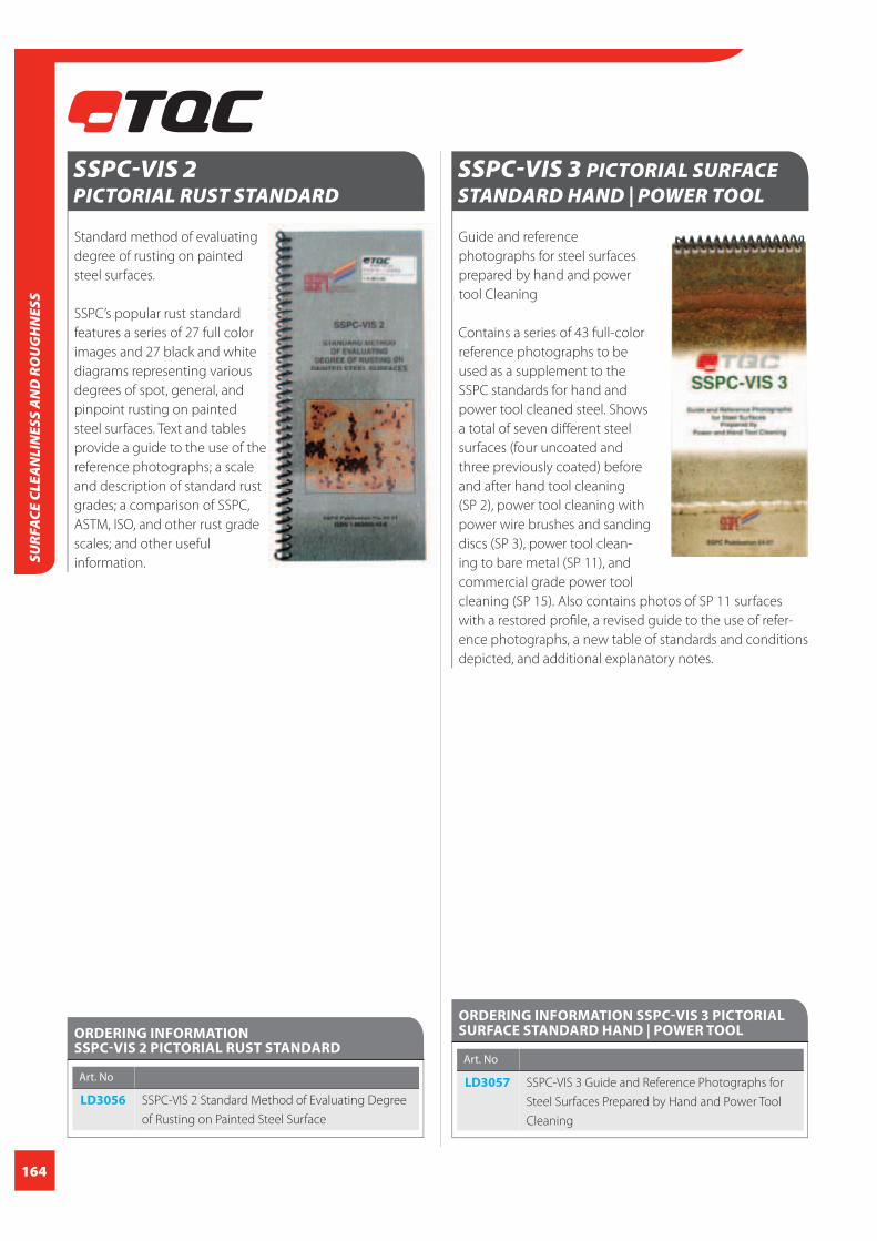
164
SURF
ACE
CLEA
NLI
NES
S A
ND
RO
UG
HN
ESS
SSPC-VIS 2 PICTORIAL RUST STANDARD
Standard method of evaluating
degree of rusting on painted
steel surfaces.
SSPC’s popular rust standard
features a series of 27 full color
images and 27 black and white
diagrams representing various
degrees of spot, general, and
pinpoint rusting on painted
steel surfaces. Text and tables
provide a guide to the use of the
reference photographs; a scale
and description of standard rust
grades; a comparison of SSPC,
ASTM, ISO, and other rust grade
scales; and other useful
information.
ORDERING INFORMATION SSPC-VIS 2 PICTORIAL RUST STANDARD
Art. No
LD3056 SSPC-VIS 2 Standard Method of Evaluating Degree
of Rusting on Painted Steel Surface
SSPC-VIS 3 PICTORIAL SURFACE STANDARD HAND | POWER TOOL
Guide and reference
photographs for steel surfaces
prepared by hand and power
tool Cleaning
Contains a series of 43 full-color
reference photographs to be
used as a supplement to the
SSPC standards for hand and
power tool cleaned steel. Shows
a total of seven diff erent steel
surfaces (four uncoated and
three previously coated) before
and after hand tool cleaning
(SP 2), power tool cleaning with
power wire brushes and sanding
discs (SP 3), power tool clean-
ing to bare metal (SP 11), and
commercial grade power tool
cleaning (SP 15). Also contains photos of SP 11 surfaces
with a restored profi le, a revised guide to the use of refer-
ence photographs, a new table of standards and conditions
depicted, and additional explanatory notes.
ORDERING INFORMATION SSPC-VIS 3 PICTORIAL SURFACE STANDARD HAND | POWER TOOL
Art. No
LD3057 SSPC-VIS 3 Guide and Reference Photographs for
Steel Surfaces Prepared by Hand and Power Tool
Cleaning

165
SURFACE CLEA
NLIN
ESS AN
D RO
UG
HN
ESS
SSPC-VIS 4 | NACE VIS 7 PICTORIAL STANDARD WATERJETTING
Guide and Reference Photo-
graphs for Steel Surfaces Pre-
pared by Waterjetting
Shows a total of six different
steel surfaces (two uncoated and
four previously coated) before
and after waterjetting. Photo-
graphs illustrate four separate
degrees of cleaning (WJ 1,
WJ 2, WJ 3, and WJ 4) for each
initial condition, with additional
photos that depict the appear-
ance light, moderate, and heavy
flash rust after cleaning. Also
contains a written guide to the
use of reference photographs
and additional explanatory
notes. Cleanliness requirements
for conditions depicted are defined by the joint SSPC/NACE
surface preparation specification for high- and ultrahigh-
pressure water jetting (SP 12/NACE 5).
ORDERING INFORMATION SSPC-VIS 4 | NACE VIS 7 PICTORIAL STANDARD WATERJETTING
Art. No
LD3058 SSPC-VIS 4/NACE VIS 7 Guide and Reference Photo
graphs for Steel Surfaces Prepared by Waterjetting
SSPC-VIS 5 | PICTORIAL STANDARDWET ABRASIVE BLAST CLEANING
Guide and Reference
Photographs for Steel Surfaces
Prepared by Wet Abrasive Blast
Cleaning
Pictorial Standard shows two
uncoated, rusted steel surfaces
(Conditions C and D) before and
after wet abrasive blast clean-
ing. Photographs illustrate two
degrees of cleaning (WAB 6 and
WAB 10) for each initial condi-
tion, with additional photos that
depict the appearance of light,
moderate, and heavy flash rust
after cleaning. Also contains a
written guide to the use of refer-
ence photographs and addition-
al explanatory notes. Cleanliness
requirements for conditions depicted are defined by the
joint SSPC/NACE surface preparation specifications for
commercial (SP 6/NACE 3) and near-white blast cleaning
(SP 10/NACE 2). Photos of commercial and near-white sur-
faces achieved by dry abrasive blast cleaning can be found
in SSPC-VIS 1.
ORDERING INFORMATION SSPC-VIS 5 | PICTORIAL STANDARD WET ABRASIVE BLAST CLEANING
Art. No
LD3059 SSPC-VIS 5/NACE VIS 9 Guide and reference photo-
graphs for steel surfaces prepared by Waterjetting

166
CLIMATETemperature, humidity and related climatic parameters are
important to many industrial processes. The application
of paint /coatings is no exception. Measuring and control-
ling climatic parameters such as relative humidity, air-
temperature, dewpoint and moisture is vital to a successful
application of high-end coating systems. Incorrect climatic
conditions during pre-treatment and application often lead
to premature failing of coating systems.
Almost each coating has its own requirements regarding
climatic conditions. Most two component epoxies require
a relatively high temperature (often more than 15°C)
combined with a low relative humidity. Moisture curing
coatings need a high humidity level in order to cure. Water
based coatings cannot be applied at very low temperatures
and too low humidity causes the paint to dry too fast while
a high humidity slows the curing process down. Surface
tolerant coatings accept a wider range of climatic condi-
tions and some coatings can even be applied underwater.
Each paint manufacturer will mention in its application
guidelines or MDS (material datasheet) specifi cally what
type of climatic conditions are required. Wrong environ-
mental conditions can lead to problems and defect such as:
DewPointA special, highly important parameter in the coating in-
dustry is DewPoint. Wikipedia describes Dewpoint as “ The
temperature to which a given parcel of humid air must be
cooled, at constant barometric pressure, for water vapour
to condense into water. The condensed water is called dew.
The dew point is a saturation temperature.
The dew point is associated with relative humidity. A high
relative humidity indicates that the dew point is closer to
the current air temperature. Relative humidity of 100%
indicates the dew point is equal to the current temperature
and the air is maximally saturated with water. When the dew
point remains constant and temperature increases, relative
humidity will decrease.”
In the surface treatment dewpoint is one of the most critical
climatic parameters. Dewpoint always has to be observed
in combination with the surface temperature. A surface
temperature that is below the dewpoint temperature of its
surrounding air will immediately show condensation. On a
rough, blast cleaned surface, the small water drops of dew
are hardly visible. However when this moisture is trapped
under a paint fi lm severe problems will arise over time.
Corrosion under the paint, poor adhesion of insuffi cient
curing are some of the possibilities.
Since the dewpoint temperature (Td) depends on the
relative humidity (RH) and air temperature (Ta) it is quite
unstable. Also the surface temperature may vary. This is
why most paint manufacturers specify a Delta T (diff erence
between Surface temperature and Dewpoint) of +3°C
(+5°F).
Picture for example the complex micro climate inside a
ship’s ballast tank that carries a warm cargo (eg. crude
oil), sailing in a cold sea in humid air. One wall of the tank
might be degrees above dewpoint while the other could
be well below.
Dewpoint under 0°C is not possible. As soon as that
temperature is reached we speak about a “Frost Point”.
When should you measure the climatic conditions? Basically the conditions should be observed prior to the
pre treatment process until the coating reached a full cure.
When the surface temperature of steel is below dewpoint
temperature the bare steel will corrode instantly after blast
cleaning.
Temperature of the coating or substrateThe coating temperature is important during application
but also during storage. Most coatings will loose their per-
formance once they have been frozen before/during their
shelf life. Viscosity of paint is in direct relationship with the
temperature of the paint which aff ects the application.
Extreme substrate temperatures also cause their share of
problems. High substrate temperatures may cause the
paint to dry too fast which could lead to pinholes or pores
for example. Low surface temperature may prevent the
paint to form a fi lm as many coatings know a so called
“Minimum Film Forming Temperature” or “MFFT” value.
Moisture in substrateThe moisture content of substrates to be coated is a
critical factor as well. Fresh moist concrete will not hold
any paint or applying a powder coating to a damp wood-
en panel will cause steam to be created when the panel
passes through the curing oven, thus causing damage to
the coating.
CLIM
ATE

167
DEWCHECK 4 SERIES 2 – DEWPOINT METER
The TQC DewCheck 4 - Dewpoint Meter (DPM)/ Dewmeter
is an extremely versatile dewpoint meter to measure and
record all climate parameters required to treat surfaces.
This easy to use and robust dewmeter conforms to
ISO 8502-4 & ASTM D3276-07 and measures the relative
humidity (%RH), ambient temperature (Ta) and surface
temperature (Ts) and calculates the dewpoint temperature
(Td) and the diff erence between the dewpoint temperature
and the surface temperature (T-delta).
The diff erence between the surface temperature and
dewpoint temperature indicates the optimal climate
conditions for painting.
All parameters can be stored in the dewmeter’s memory,
tagged with a date and time. Once the measured data has
been stored in memory in one of the eight custom
pre-named batches, the climate conditions can be
downloaded and analyzed within TQC Ideal Finish Analysis.
Reports can include the measured ambient, surface and
dew point temperature that in combination with the
relative humidity parameter prove the coatings have been
applied according to their specifi cations.
FEATURES
Large illuminated graphic display One-hand operation Simple menu-driven user interface Extensive data-logging capabilities, readings are time and date stamped and stored on the gauge USB-Interface connects the unit to the PC for programming and downloading data. To be used as “on the spot” inspectors tool or “stand- alone” data logger Heavy duty ergonomic case
Set limits for each parameter Acoustic and visual alarms Select Celsius / Fahrenheit Automatic trend indicator shows the trend of climatic conditions (rising, falling, stable) High-end industrial sensors and built- in probes Integrated ‘back-up’ LED fl ashlight DewLog temperature and humidity monitoring software included Two year valid calibration certifi cate!
STANDARDS
ISO 8502-4
ASTM D3276
BS 7079-B4
NACE RP prop 97
CLIMATE
Hysteresis
Wiki states: “Hysteresis is the dependence of a system not only on its current environment but also on its past environment.”
Especially after condensation many RH-sensors “memorize” the high humidity level and introduce a false (too high) read-ing.
The new ISO 8502-4 standards states the following:
Due to the sensitivity to hysteresis electronic dewpoint gauges
should be handled acc. to manufacturerspecifi cations and the probability for hysteresis should be prevented to maintain correct results. Hysteresis can give off set reading up to 10% and last depending on probe type up to multiple weeks. To prevent hysteresis the probe should not be exposed to extreme temperature / humidity shocks in both directions.
DewCheck’s RH-probe is virtually immune for the hysteresis eff ect.
CCICALIBRATION
CERTIFICATION
INCLUDED

168
HumidityAccuracy (0…80 °C, 0…176 °F) +/- 3 % RH
Measurement resolution 0.1 %
Measurement range 0…100 % RH
TemperatureTemperature Ta (Air)
Accuracy +/- 0.5 °C, +/- 1 °F
(over the full measurement range)
Measurement resolution 0.1 °C, 0.1 °F
Measurement range - 20…+ 80 °C, - 4…+ 176 °F
Temperature Ts (Surface)
Accuracy +/- 0.5 °C, +/- 1°F
(over the full measurement range)
Measurement resolution 0.1 °C, 0.1 °F
Measurement range - 30…+ 60 °C, - 22…+ 140 °F
Temperature Ts (Surface External)
Accuracy +/- 0.5 °C, +/- 1 °F
(over the full measurement range)
Measurement resolution 0.1 °C, 0.1 °F
Measurement range - 30…+ 60 °C, - 22...+ 140 °F
Display
Graphical presentation with backlight
Operating temperature range - 20 °C…60 °C, - 4...+ 140 °F
Keys Menu 3
On / off , 1 (electronic), LED fl ashlight
1 (electronic)
TECHNICAL SPECIFICATIONS DEWCHECK 4 SERIES 2 – DEWPOINT METER
MemoryType Dynamic
Memory size manual logging 6000 records
Record content manual logging time/date, humidity,Ta,
Ts, Td,Tdelta, status byte for alarm
Memory size interval logging 12000 records
Record content interval logging Humidity, Ta and Ts. Other
parameters and date and time
are calculated
Batches 8 Batches max.
Measurement / featuresLimits Adjustable for each parameter
Lo-Hi Alarms Beep sound , symbol in display and
RED Led
Hold/freeze function Yes
Data storage Two modes: Manual and interval (auto)
Data recall Gauge displays average, min/max
of each batch. Downloading to
PC possible via optional adapter
Battery indicator Yes, detailed
Trend indicator Yes
User interface Menu driven through
up/down/enter key.
Languages 4 languages, English, German,
French, Spanish
Extra Built-in bright white LED orientation
fl ashlight
ORDERING INFORMATION
DEWCHECK 4 SERIES 2 – DEWPOINT METER
Art. No
DC7100 DewCheck 4 Series 2
Scope of supply: TQC Dewcheck 4 dewpoint gauge, leather pouch,
wrist strap, USB cable, calibration certifi cate, batteries, manual
ACCESSORIES / SPARES
DC7520 Docking Station for DewCheck Series 2
DC7510 USB communication cable
DC7010 Spare leather pouch
IDEAL FINISH ANALYSIS
CLIM
ATE

169
SLING PSYCHROMETER
Bacharach type sling Psychrometer for indicating percent
relative humidity on the basis of the wet bulb-dry bulb
thermometer principle. The plastic case of the instrument
is equipped with conversion scale for calculating the
percent relative humidity.
FEATURES
- Universal application Fast response Compact size High accuracy
TECHNICAL SPECIFICATIONS SLING PSYCHROMETER
Material Plastic
Dimensions 30x30x205 mm / 1,18x1,18x8,07 inch
Weight 100 g / 3,53 oz.
ORDERING INFORMATION SLING PSYCHROMETER
Art. No
TM0081 Sling Psychrometer
Scope of supply: Sling Psychrometer
For optimal use of the data
logging facilities of the
instrument the TQC Dew-
Check 4 Docking Station is
available.
The Docking Station is
provided with 3 strong
Neodymium magnets which
hold instrument and dock
fi rmly against ferrous steel
surfaces. The delivery of the
Docking Station includes a
magnetic surface tempera-
ture sensor which overrides
the instrument’s integrated
surface temperature sensor
in order to guarantee
correct TS-readings.
DEWCHECK 4 DOCKING STATION
FEATURES
Optimizes DewCheck 4’s data logging facilities Strong neodymium magnets Magnets lined with rubber to prevent to prevent damaging and sliding Magnetic surface temperature sensor for correct TS-readings
TECHNICAL SPECIFICATIONS DEWCHECK 4 DOCKING STATION
Material plastic
Weight 81 g / 2,86 oz
Dimensions 41x18x50 mm / 1,61x0,71x1,97 inch
Connections thermocouple, USB
ORDERING INFORMATION DEWCHECK 4 DOCKING STATION
Art. No
DC7520 DewCheck 4 Docking Station
Scope of supply: Dock unit, magnetic surface temperature probe,
USB cable, allen key2,5 mm, TQC Ideal Finish Analysis evaluation
software (download)
CLIMATE

170
FEATURES
Readings in °C and °F Can be used in vacuum No plastic parts on the outside of the thermometer
ORDERING INFORMATION MAGNETIC THERMOMETER FOR SURFACE TEMPERATURE
Art. No
TM0015 TQC Magnetic Thermometer for surface temperature
Scope of supply: Magnetic Thermometer for surface temperature
leather pouch with belt-clip
The TQC Magnetic Thermometer measures surface tem-
perature. The thermometer can easily be placed on ferrous
substrates with the strong magnet on the back. Surface
temperature can be read out in both °C and °F. Measuring
Range is -10°C to + 70°C; +14°F to +60 °F. The diameter of
the thermometer is 65 mm / 2,56 inch.
The TQC Magnetic Thermometer for surface temperature
comes in a genuine leather pouch with belt-clip.
MAGNETIC THERMOMETER FOR SURFACE TEMPERATURE
TECHNICAL SPECIFICATIONS MAGNETIC THERMOMETER FOR SURFACE TEMPERATURE
Measuring range -10°C..+70°C/+14°F to +160 °F
Material Dimensions 60 x 60 x 25 mm 2,36 x 2,36 x 0,98 inch
Diameter Thermometer 65 mm / 2,56 inch
Weight 100 g / 3,53 oz.
DEWPOINT CALCULATOR
The TQC Dewpoint calculator is a handy tool to determine
dewpoint temperature based upon the measurements
from the sling psychrometer.
Includes a Celsius / Fahrenheit converter.
FEATURES
Easy to use Easy to clean
TECHNICAL SPECIFICATIONS DEWPOINT CALCULATOR
Material Plastic
Dimensions 140x140x6 mm / 5,51x5,61x0,24 inch
Weight 80 g / 2,82 oz.
ORDERING INFORMATION DEWPOINT CALCULATOR
Art. No
TM0040 TQC Dewpoint Calculator
CLIM
ATE

171
THERMO-HYGROMETER
The TQC Thermo hygrometer is a
simple hand-held digital thermo/
hygrometer. Temperature and air hu-
midity are displayed simultaneously.
Equipped with MIN/MAX memory,
°C/°F selection, HOLD function and
dewpoint indication.
The TQC Thermo hygrometer
operates 10.000(!) hours on 3
batteries type AAA and switches
itself off after 10 min.
FEATURES
Hold function Max and min values are stored Display with backlight Dewpoint indication Battery indication Integral probe
TECHNICAL SPECIFICATIONS THERMO-HYGROMETER
temperature Rel. humidity
Range -20 to 70°C / 0 to 100% rv
-4°F to 158°F
Resolution 0.1°C/°F 0.1%rh
Accuracy +/-1°C +/-1 digit +/-2% (10 to 90 %RV)
Sensor type silicone capacitance
bandgap polymer
Battery 3 x 1.5 volt AAA
Battery lifetime minimum of 5 years (10000 hours)
Display 12mm LCD / 0,47 inch LCD
Dimensions 25x56x128 mm / 0,98x2,2x5,04 inch
Weight 130 g / 4,6 oz.
ORDERING INFORMATION THERMO-HYGROMETER
Art. No
RV2100 Thermo-hygrometer
Scope of supply: TQC Thermo hygrometer, soft pouch, manual ,
batteries
Digital thermo hygrometer for
indoor use, to be used as bench
top or wall model.
Very large display (56x40 mm /
2,2x1,57 inch), readable up to a
distance of approximately 10 m /
32,8 ft.
Memory for minimum and
maximum values and humidity
readings, toggle between °C/ °F;
time display; alarm function.
DIGITAL THERMO HYGROMETER
FEATURES
Large display Time, temperature and humidity at a glance Toggle between °C/ °F Alarm function Bench top and wall model in one
TECHNICAL SPECIFICATIONS DIGITAL THERMO HYGROMETER
Temperature range 0°C to 50°C / 32°F to 122°F
Temperature resolution 0.1°C / 0.1°F
Temperature accuracy +/-1.0°C / 0.1°F
Humidity range 10 % RH - 90 % RH
Humidity Accuracy +/- 5 %
Battery AAA
Material Plastic
Dimensions 105 x 60 x 10 mm / 4,13 x 2,12 x 0,35 inch
Dimensions display 56 x 40 mm / 2,2 x 1,57 inch
ORDERING INFORMATION DIGITAL THERMO HYGROMETER
Art. No
RV1610 TQC Digital Thermo Hygrometer
Scope of supply: Digital Thermo-Hygrometer Wall mount clip
CLIMATE

172
CLIM
ATE
TEMPERATURE INDICATION STICKERS
Are available in different series with 1, 5, 6, 8 or 10 tempera-
tures per sticker. The indicators are irreversible: the highest
measured temperature always remains visible, for many
months. This makes the indication stickers ideal for control
purposes. Applications can be found, among others, in
electronics, food, and pharmaceutical industries, and also in
the oven and engine construction businesses.
ORDERING INFORMATION TEMPERATURE INDICATION STICKERS
Art. No Art. No
TC5020 Temperature indication stickers, Series 5 range 1
10 strips with 40°C, 43°C, 46°C, 49°C, 54°C
TC5025 Temperature indication stickers, Series 5, Range 2
10 strips with 60°C, 66°C, 71°C, 77°C, 82°C
TC5030 Temperature indication stickers, Series 5, Range 3
10 strips with 88°C, 93°C, 99°C, 104°C, 110°C
TC5035 Temperature indication stickers, Series 5, Range 4
10 strips with 116°C, 121°C, 127°C, 132°C, 138°C
TC5040 Temperature indication stickers, Series 5, range 5
10 strips with 143°C, 149°C, 154°C, 160°C, 166°C
TC5045 Temperature indication stickers, Series 5, range 6
10 strips with 171°C, 177°C, 182°C, 188°C, 193°C
TC5050 Temperature indication stickers, Series 5, range 7
10 strips with 199°C, 204°C, 210°C, 216°C, 224°C
TC5055 Temperature indication stickers, Series 5, Range 8
10 strips with 232°C, 241°C, 249°C, 254°C, 260°C
TC6010 Temperature indication sticker, Series 6, Range A
10 strips with 60°C, 65°C, 71°C, 77°C, 82°C, 88°C
TC6030 Temperature indication stickers, thermindex serie 6
range C 10 strips with 149°C, 154°C, 160°C, 166°C,
171°C and 177°C
TC8010 Temperature indication stickers, thermindex serie 8
range A 10 strips with 40°C, 43°C, 46°C, 49°C, 54°C,
60°C, 66°C, 71°C
TC8020 Temperature indication stickers, thermindex serie 8
range B 10 strips with 77°C, 82°C, 88°C, 93°C, 99°C,
104°C, 110°C, 116°C
TC8030 Temperature indication stickers, thermindex serie 8
range C 10 strips with 121°C, 127°C, 132°C, 138°C,
143°C, 149°C, 154°C, 160°C
TC8040 Temperature indication stickers, thermindex serie 8
range D 10 strips with 166°C, 171°C, 177°C, 182°C,
188°C, 193°C, 199°C, 204°C
TC8050 Temperature indication stickers, thermindex serie 8
range E10 strips with 210°C, 216°C, 224°C, 232°C,
241°C, 249°C, 254°C, 260°C
TC9000 Temperature indication stickers, 1000 stickers
(sheets) serie 1
TC9040 * Temperature indication stickers, thermindex serie 1
range 40°C
TC9044 * Temperature indication stickers, thermindex serie 1
range 44°C
TC9046 * Temperature indication stickers, thermindex serie 1
range 46°C
TC9049 * Temperature indication stickers, thermindex serie 1
range 49°C
TC9054 Temperature indication stickers, thermindex serie 1
range 54°C
TC9060 * Temperature indication stickers, thermindex serie 1
range 60°C
TC9065 * Temperature indication stickers, thermindex serie 1
range 65°C
TC9071 * Temperature indication stickers, thermindex serie 1
range 71°C
TC9077 * Temperature indication stickers, thermindex serie 1
range 77°C
TC9082 * Temperature indication stickers, thermindex serie 1
range 82°C
TC9088 * Temperature indication stickers, thermindex serie 1
range 88°C
TC9093 * Temperature indication stickers, thermindex serie 1
range 93°C
TC9099 * Temperature indication stickers, thermindex serie 1
range 99°C
TC9104 * Temperature indication stickers, thermindex serie 1
range 104°C
TC9110 * Temperature indication stickers, thermindex serie 1
range 110°C
TC9116 * Temperature indication stickers, thermindex serie 1
range 116°C
TC9121 * Temperature indication stickers, thermindex serie 1
range 121°C
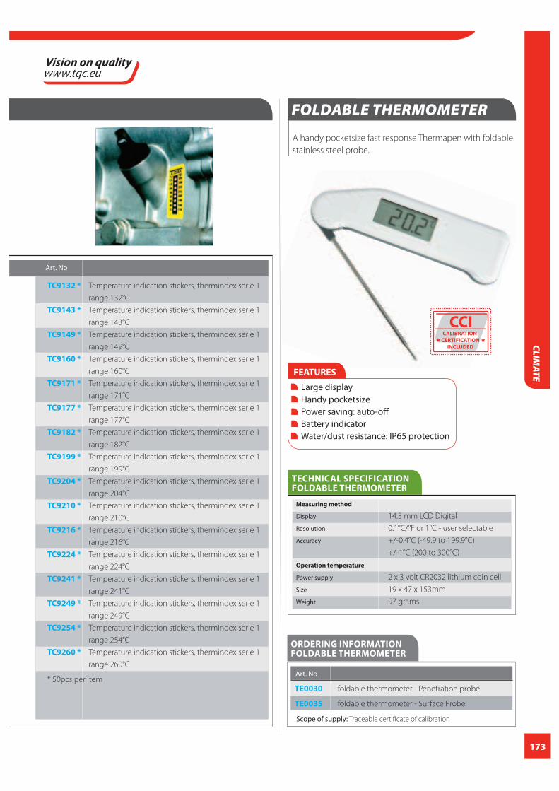
173
Art. No
TC9132 * Temperature indication stickers, thermindex serie 1
range 132°C
TC9143 * Temperature indication stickers, thermindex serie 1
range 143°C
TC9149 * Temperature indication stickers, thermindex serie 1
range 149°C
TC9160 * Temperature indication stickers, thermindex serie 1
range 160°C
TC9171 * Temperature indication stickers, thermindex serie 1
range 171°C
TC9177 * Temperature indication stickers, thermindex serie 1
range 177°C
TC9182 * Temperature indication stickers, thermindex serie 1
range 182°C
TC9199 * Temperature indication stickers, thermindex serie 1
range 199°C
TC9204 * Temperature indication stickers, thermindex serie 1
range 204°C
TC9210 * Temperature indication stickers, thermindex serie 1
range 210°C
TC9216 * Temperature indication stickers, thermindex serie 1
range 216°C
TC9224 * Temperature indication stickers, thermindex serie 1
range 224°C
TC9241 * Temperature indication stickers, thermindex serie 1
range 241°C
TC9249 * Temperature indication stickers, thermindex serie 1
range 249°C
TC9254 * Temperature indication stickers, thermindex serie 1
range 254°C
TC9260 * Temperature indication stickers, thermindex serie 1
range 260°C
* 50pcs per item
A handy pocketsize fast response Thermapen with foldable
stainless steel probe.
FOLDABLE THERMOMETER
FEATURES
Large display Handy pocketsize Power saving: auto-off Battery indicator Water/dust resistance: IP65 protection
TECHNICAL SPECIFICATION FOLDABLE THERMOMETER
Measuring method
Display 14.3 mm LCD Digital
Resolution 0.1°C/°F or 1°C - user selectable
Accuracy +/-0.4°C (-49.9 to 199.9°C)
+/-1°C (200 to 300°C)
Operation temperature
Power supply 2 x 3 volt CR2032 lithium coin cell
Size 19 x 47 x 153mm
Weight 97 grams
CLIMATE
ORDERING INFORMATION FOLDABLE THERMOMETER
Art. No
TE0030 foldable thermometer - Penetration probe
TE0035 foldable thermometer - Surface Probe
Scope of supply: Traceable certificate of calibration
CCICALIBRATION
CERTIFICATION
INCLUDED

174
CLIM
ATE
ORDERING INFORMATION USB DATA LOGGER FOR TEMPERATURE AND RH
Art. No
HM9000 USB datalogger for temperature and
relative humidity
FEATURES
Memory for 32.000 readings (16000 temperature- and 16000 humidity readings) Dew point indication Status indication Multi-mode to start logging Selectable measuring interval ( 2, 5, 10 or 30 seconds; 1, 5, 10 or 30 minutes; 1, 2, 3, 6, 12 or 24 hours) User-selectable alarm USB interface Analysis software Long battery life
USB DATA LOGGER FOR TEMPERATURE AND RH
USB data logger for temperature and relative humidity. The
USB data logger has a memory for 32.000 readings (16000
temperature- and 16000 humidity readings), a dewpoint
indication, a user-selectable alarm. The measuring interval
can be set to 2, 5, 10 or 30 seconds; 1, 5, 10 or 30 minutes;
1, 2, 3, 6, 12 or 24 hours. Supplied with analysis software.
TECHNICAL SPECIFICATIONS USB DATA LOGGER FOR TEMPERATURE AND RH
Relative Humidity
Range 0-100%
Accuracy (0 to 20% and 80 to 100%) +/- 5.0%
Accuracy (20 to 40% and 60 to 80%) +/- 3.5%
Accuracy (40 to 60%) +/- 3.0%
Temperature
Range -40°C to 70 °C
Accuracy (-40°C to -10°C and +40°C to +70°C) +/- 2 °C
Accuracy (-10°C to +40°C) +/- 1°C
Accuracy (-40°F to +14°F and 104°F to 158°F) +/- 3.6°F
Accuracy (+14°F to 104°F) +/-1.8°F
Dew Point temperature
Range -40°C to 70°C (-40°F to 158°F)
Accuracy (25°C, 40% to 100% Relative Humidity) +/- 2.0°C (+/- 4.0°F)
Logging rate Selectable sampling interval: 2, 5, 10 or 30 seconds;
1, 5, 10 or 30 minutes; 1, 2, 3, 6, 12 or 24 hour
Operating temperature -35°C to 80°C (-31°F to 176°F)
Battery type 3.6V Lithium (1/2AA) (SAFT LS14250, Tadiran TL-5101 or equivalent)
Battery life 1 year(typ.) depending on logging rate, ambient temperature &
use of Alarm LED’s
Dimensions, weight 101x25x23 mm (4x1x0.9”) / 172 g (6oz)

175
MOISTUREThe term “Moisture“ is often confused with “humidity”. Humidity or
better relative humidity is defi ned as “the ratio of the partial pressure
of water vapour in the mixture to the saturated vapour pressure of
water at a prescribed temperature.”
Products to defi ne humidity and other climatic parameters are
presented in our section Climatic Conditions. Moisture refers to the
presence of a liquid, especially water, often in trace amounts. The
moisture content of materials to be coated is an important para-
meter. Fresh concrete for example has a very high moisture content.
The moisture evaporates through the surface of that concrete. If the
surface is closed off with a non-permeable coating layer the mois-
ture is trapped and will cause damage to the coating over time. The
same goes for timber which is not kiln- or air dried. Coating of moist
materials often leads to adhesion failures. The moisture of a substrate
is not just critical for coatings also (wooden) fl ooring, wall paper or
other materials that cover a substrate will demand a certain moisture
content of that substrate. Further moisture can be found in powder
or grain-like materials such a cereals, pigments, powder coatings etc..
There various systems to defi ne the moisture content of a material.
Electrical conductivity / resistance and impedance
These instruments measure the resistance of an electrical signal
between points at the material to be measured. Various techniques
are being used to enhance accuracy. There a simple instruments that
just provide an indication of the moisture content but also sophis-
ticated gauge that provide accurate readings. This kind of meters
are often used to measure in solid materials like timber, concrete,
masonry etc..
Reagent pressure test or carbide test
This system is based upon a chemical reaction of water with carbide.
A defi ned quantity of material to be measured and carbide is placed
in a special closed container and then mixed. The reaction of the
water in the material and the carbide creates a pressure which can
be read on the pressure gauge which is integrated in the container.
There is a direct ration between the pressure and the water content.
This type of test are not so easy to perform but the results are very
accurate. Often these test are done on concrete or stone.
Gravimetric or moisture balance
This method is based upon the loss of weight of a material after it is
dried. A special analytic balance is used to measure the total weight
of the sample. Than the sample is dried with a special device which
is integrated in the balance. The evaporation of the moisture will
reduce the weight of the sample. When the weight of the sample
remains stabile it indicates all moisture has been taken out of the
material and the drying process stops. The diff erence between “wet”
and “dry” sample is an accurate indication of the moisture content.
This type of test is mainly used for grain- shaped materials or
powders.
MO
ISTURE

176
CONCRETE MOISTURE METER
The TQC Concrete moisture meter is a non-destructive
moisture meter for concrete. By means of measuring the
electrical impedance the moisture content of concrete can
easily be determined by just pressing the instrument against
the concrete surface.
The electrical impedance is measured through genera-
ting a low frequency electric fi eld between 8 electrodes at
the bottom of the instrument. Depending on the moisture
content the measurements are made to a depth of several
centimetres.
This system is not suitable to measure through electrically
conductive materials like metal or rubber linings or wet
surfaces.
TQC Concrete Moisture meters are ideal to quickly test large
concrete fl oors or constructions which have to be painted
or where (wooden) fl oorings are being installed.
Four scales allow fl exible use of the instrument as an accu-
rate measuring device or just as a detector to fi nd moisture
traces or leakage.
1. Concrete 0-6% H2O
2. ~ Carbide Method 0-6% H2O
3. Relative Scale 0-100%
4. ~ 15. Scale 0.3-15.3 m
Convenient features such as a “max-hold” for hard to reach
places and “auto-switch off ” are integrated.
FEATURES
Easy-to-use Ideal for a quick test Non-destructive Normal and max. hold-mode 4 Available scales Auto switch-off
ORDERING INFORMATION CONCRETE MOISTURE METER
Art. No
LI9200 TQC Concrete moisture meter
Scope of supply: Concrete moisture meter, soft pouch, manual
TECHNICAL SPECIFICATIONSCONCRETE MOISTURE METER
Material Plastic
Dimensions 147x89x33 mm / 5,79x3,5x1,3 inch
Power supply 2x AA battery
Battery lifetime 20 hours
Display monochrome 128 x 64 pixels, size 61 x 33mm
with backlight
Operating temperature range 5°- 40°C / 42-104°F
Accuracy +/-0.5%
Scales Concrete, Carbide Method,
Relative Scale, 15. Scale
MO
ISTU
RE

177
CARBIDE - METHOD HYGROMETER
High precision destructive S2000 measuring system for
detecting moisture in concrete, sand cement and other
bricky material. The water present in the sample reacts
(chemically) with calcium carbide. This produces pressure
in the vessel, which is proportional to the residual moisture
content. Insensitive to external influences, always displays
the right value. Complete set in carrying case with balance,
pressure cylinder, calcium carbide and cleaning tools.
TECHNICAL SPECIFICATIONS CARBIDE - METHOD HYGROMETER
Model Classic (B)
Pressure measurement principle Relative
Dependence of indicated pressure Correlated
on ambient pressure
Splashproof/dustproof Standard
Online check No
Measurement duration indication No
Logging option on site No
Measured value storage No
Individual company logo No
Maintenance effort Check regularly
Pressure gauge accuracy class 1,6
Measuring range 0 to 1,6 bar
Overload protection Moderate
Typ. error (mbar) +/- 25,4
Direct read-off of CM% moisture 20 g, 50 g, 100 g
Other weights No
Electrical power supply None
MO
ISTURE
ORDERING INFORMATION CARBIDE - METHOD HYGROMETER
Art. No
LI0055 CM Carbide method Hygrometer, Model “Classic”
Scope of supply: Precision spring balance up to 100 g, Weighing
beakers, Full tool kit for sample conditionin, Ball set with 4 steel balls,
20 carbide ampoules, 3 test ampoules with 1.00 g water for checking
pressure gauge and checking for leaks, 3 spare seals, both for pressure
gauge and for pressurised cylinder + spoon and cleaning brush, Clear
Instructions for Use in addition to Quick-Start-Guide, Metal carrying case
ACCESSORIES / SPARES
LI0056 Calcium carbid ampoules, 100 pcs

178
KARSTEN TUBE PENETRATION TEST
The TQC Karsten Tube Penetration Test is a simple test for
measuring the degree or water penetration into buil-
ding materials such as concrete, stone and plaster. The test
consists of a glass tube fi lled with water, bonded to the
test material with plastiline. Water pressure is then exerted
on the surface. A graduated scale indicates, over time, the
amount or water penetrated into the surface.
The TQC Karsten Tube Penetration Test contains 3 tubes
for horizontal surfaces, 3 tubes for vertical surfaces (or at
choice any other combination of total 6 tubes), a water
bottle, market and putty to place the tubes leak-tight on the
surface. Additional vertical or horizontal tubes are available
on request.
FEATURES
Simple For both horizontal and vertical surfaces
ORDERING INFORMATION KARSTEN TUBE PENETRATION
Art. No
LI7500 Moisture Karsten Penetration Test
Scope of supply: 3 tubes for horizontal surfaces, 3 tubes for vertical
surfaces, 1 water bottle, Market and putty to place the tubes leak-tight
on the surfacel
ACCESSORIES / SPARES
LI7505 Karsten tube vertical
LI7506 Karsten tube horizontal
LI7507 Plasticine 250 gr for Karsten-tube
penetration test
MO
ISTU
RE
WOOD MOISTURE GAUGE
Non-destructive instrument for measuring moisture levels
in wood. Measures up to a depth of approx. 20 mm. The in-
strument contains the calibration lines of 25 diff erent types
of wood, guaranteeing a high degree of accuracy.
The selected wood type and the measuring results are im-
mediately displayed.
The instrument is also capable
of detecting the moisture
content of concrete.
ORDERING INFORMATION WOOD MOISTURE GAUGE
Art. No
LI7000 Caisson Wood Moisture Detection meter VID6
Scope of supply: Pouch
FEATURES
Measures up to a depth of approx. 20 mm Calibration lines of 25 diff erent types of wood High degree of accuracy Auto Power Off
TECHNICAL SPECIFICATIONS WOOD MOISTURE GAUGE
Measuring method Non-Destructive
Display Dot Matrix LCD display
Range 7 – 40%
Resolution 0.1%
Power supply 9V Battery
Size 150 x 80 x 30 mm
SEE ALSOPAGE71

179
MO
ISTURE
MINI-LIGNO ‘CLASSIC PLUS’ WOOD MOISTURE METER
Wood moisture meter in pocket size format. The Mini LIGNO
classic+ is the succession model of the mini LIGNO X. With
the mini LIGNO classic+ you have the option between four
wooden groups, 16 single species of wood and an reference
scale. Because of the wide range of options, the Classic+ is
suited particularly for wood
buyers, wood traders,
wood processors,
saw companies and
for the dry masters.
FEATURES
Pocket size format 4 wood groups, 16 species of wood and one reference scale 2 sets of pins
TECHNICAL SPECIFICATIONS MINI-LIGNO ‘CLASSIC PLUS’ WOOD MOISTURE METER
Measuring method Destructive
Display LCD
Measuring area 6 – 75%
Temperature area 20°C
Pins 5.5 mm and 9 mm
Power supply 9V battery
Size 129 x 63 x 27.5 mm
Weight 200 g
ORDERING INFORMATION MINI-LIGNO ‘CLASSIC PLUS’ WOOD MOISTURE METER
Art. No
LI0007 MINI-LIGNO “CLASSIC+” Wood Moisture Meter
Scope of supply: Mini Ligno Classic+ with 2 sets of pins and pouch
WOOD MOISTURE TESTER WITH TEMPERATURE COMPENSATION
This instrument is a conductivity moisture meter specifically
designed for the timber industry. The instrument has eight
calibration scales, enabling the user to take accurate mois-
ture measurements in 150 wood species. Moisture measure-
ments can be taken using the integral pin electrodes, or
using the heavy duty moisture probe. When used with the
temperature probe, the moisture
measurements are automatically
corrected with respect to
temperature. A calibration
tester is integrated into
the protective cap.
FEATURES
Wood moisture tester Pin electrode Temperature probe 2 AAA batteries Manual
ORDERING INFORMATION WOOD MOISTURE TESTER WITH TEMPERATURE COMPENSATION
Art. No
LI9050 wood moisture tester + temperature
compenstion ST-129 Wood moisture tester
Scope of supply: Mini Ligno Classic+ with 2 sets of pins and pouch
TECHNICAL SPECIFICATIONS SWOOD MOISTURE TESTER WITH TEMPERATURE COMPENSATION
Measuring principle Electrical resistance
Elektrode length 8mm
Elektrodes Integrared, replaceable
Measuring range Wood: 6- 99,9%
Display Resolution Wood: 0,1%
Battery 2x AAA
Housing Impact-proof plastic housing
Ambient temperature 0- 40C°
Ambient moisture 0- 85%
Size 180mm x 50mm x31mm
Weight 175 g
180
TEMPERATURETemperature is one of the most important parameters in about every process. It is a physical
property of matter that quantitatively expresses the common notions of hot and cold. Objects
of low temperature are cold, while various degrees of higher temperatures are referred to
as warm or hot. Quantitatively, temperature is measured with thermometers, which may be
calibrated to a variety of temperature scales.
Temperature scales
Worldwide the majority uses the Celsius scale (°C) for most temperature measurements. It has
the same incremental scaling as the Kelvin scale used by scientists, but fi xes its null point, at
0°C = 273.15K, the freezing point of water. A few countries, most notably the United States,
use the Fahrenheit scale for common purposes, a historical scale on which water freezes at 32
°F and boils at 212 °F.
For practical purposes of scientifi c temperature measurement, the International System of
Units (SI) defi nes a scale and unit for the thermodynamic temperature by using the easily
reproducible temperature of the triple point of water as a second reference point. For
historical reasons, the triple point is fi xed at 273.16 units of the measurement increment,
which has been named the kelvin in honor of the Scottish physicist who fi rst defi ned the
scale. The unit symbol of the kelvin is K.
Thermodynamics
Temperature is one of the principal properties studied in the fi eld of thermodynamics.
Particularly important in this fi eld are the diff erences in temperature between regions of
matter, because such diff erences are the driving force for heat,[1] which is the transfer of
thermal energy. Spontaneously, heat fl ows only from regions of higher temperature to
regions of lower temperature. If no heat is transferred between two objects, the objects
have the same temperature. Source: Wikipedia
Temperature in the paint and coatings industry
In the paint and coatings industry there are many examples and applications where
temperature plays a key role.To name a few:
application.
based coatings in particular.
For some applications single spot measurements are suffi cient. Other situations require a
complete temperature registration during the entire production process.
Many diff erent methods and instruments are available varying from simple bi-metal ther-
mometers, contact- or non contact (infrared) meters to advanced thermo graphic cameras or
sophisticated dataloggers.
TEM
PERA
TURE

181
THERMOMETER TE1000
A tough, high-quality thermometer suitable for use with the
interchangeable type ‘K’ thermocouple probes.
The practical design, robust casing, large push buttons and
the protective holster supplied with the instrument make
the TE1000 suitable for use in heavy-duty conditions.
The large display panel enables readability at a distance.
Equipped with functions for holding the current value as
well as the maximum value.
FEATURES
User selectable °C or °F User selectable 0.1°C or 1°C(0.1°F or 1°F) resolution K-type thermocouples Wide variety of interchangeable thermocouple probes Max hold and data hold LCD display with backlight Accessories: 9V battery, holster with stand and temperature probe.
TECHNICAL SPECIFICATIONS THERMOMETER TE1000
Function Temperature
Range -50~1300°C +/-(0.5%+/-1°C)
-58~2000°F +/-(0.5%+/-2°F)
Basic Accuracy Resolution 0.1° or 1°
Reading rate 2.5 times per second
Input connector Accepts standard miniature thermocouple
connectors
(flat blades spaced 7,9 mm centre to centre)
Dimensions 175x76x 43 mm / 6,89x2,99x1,69 inch
Weight 320 g / 11,29 oz.
ORDERING INFORMATION THERMOMETER TE1000
ACCESSORIES / SPARES
TE5103 Temperature probe, type 80111,
right angle surface probe, max.200ºC / 392oF
TE5104 Temperature probe, type 80104, Liquid probe,
max. 1100ºC / 2012oF
TE5105 Temperature probe, type 80105, Liquid probe,
max. 900ºC / 1652oF
TE5106 Temperature probe, type 80106, Sharp needle
probe, 130x3 mm, max.600ºC / 1112oF
TE5107 Temperature probe, type 80107, Sharp needle
probe, 130x1,5 mm, max.600ºC / 1112oF
TE5108 Temperature probe, type 80108, Air and gas
probe, max. 600ºC / 1112oF
TE5109 Temperature probe, type 80109, Pipe clamp
< Ø35 mm, max. 200ºC / 392oF
TE5110 Temperature probe, type 80110, Surface
probe, max. 900 °C / 1652oF
TE5112 Temperature probe, type 133-080, Pipe probe
< Ø150 mm with velcro fastening,
max. 100°C / 212oF
TE5120 Temperature probe, type 333-175, Deep
freeze probe, max. 260ºC / 500oF min. -
180ºC / -292oF
TE5125 Temperature probe, type133-130 ETI Heavy
Duty asphalt probe, max. 300 °C / 572oF
Art. No
TE1000 TQC Thermometer for thermocouples
Scope of supply: Thermometer, Pouch, wire probe
TEMPERATU
RE

182
TEMPERATURE PROBESProbes for instruments suited for changeable probes
(type ‘K’) using a plug connection.
Can also be manufactured according to customer
specifications. Contact us for further details.
TECHNICAL SPECIFICATION TEMPERATURE PROBES
ACCESSORIES / SPARES
TE1000 TQC Thermometer for thermocouples
Art. No Probe model Probe type Max. temp Dimensions Additional info
TE5103 Right angle surface type 80111 max.200oC /392oF 130x8 mm / point 15x30 mm /
probe 5,12x0,31 inch 0,59x1,18 inch
TE5104 Liquid probe Type 80104 max. 1100oC /2010oF 130x3 mm /
5,12x0,12 inch
TE5105 Liquid probe, Type 80105 max. 900oC /1652oF 130x1.5 mm /
5,12x0,59 inch
TE5106 Sharp needle probe Type 80106 max.600oC /1112oF 130x3 mm /
5,12x0,12 inch
TE5107 Sharp needle probe Type 80107 max.600oC /1112oF 130x1,5 mm /
5,12x0,59 inch
TE5108 Air and gas probe Type 80108 max. 600oC /1112oF 130x6 mm /
5,12x0,24 inch
TE5109 Pipe clamp Type 80109 max. 200oC /392oF < Ø35 mm /
1,42 inch
TE5110 Surface probe Type 80110 max. 900oC /1652oF 130x8 mm /
5,12x0,31 inch
TE5112 Pipe probe with Type 133-080 max. 100oC /212oF < Ø150 mm /
velcro fastening 5,91 inch
TE5120 Deep freeze probe Type 333-175 max. 260oC /500oF 160x8mm / min. -180oC /-292oF
6,3x0,31 inch
TE5125 ETI Heavy Duty Type133-130 max. 300oC /572oF 500x8 mm / with sturdy T-shaped
asphalt probe 19,69x0,31 inch hand-grip
TEM
PERA
TURE

183
ORDERING INFORMATION MAGNETIC INFRARED THERMOMETER POCKET SIZE
Art. No
TE1004 Infrared thermometer pocket size with laser pointer
Scope of supply: Infrared thermometer, lanyard
A pocket size infrared thermometer
to measure surface temperature
without making contact. The laser
pointer identifi es the target area
easily. An illuminated display allows
working in dark or poorly lit envi-
ronments.
Fast and simple operation, just
point and shoot and the surface
temperature is shown immediately.
Typical applications are with
surfaces that are
hard to reach,
moving objects or
electrical parts.
INFRARED THERMOMETER POCKET SIZE
TECHNICAL SPECIFICATIONS INFRARED THERMOMETER POCKET SIZE
Range -30 to 270°C / -22 to 518°F
Response time less than 1 second
Resolution 1°C/°F
Distance to Spot size 6:1
Emissivity fi xed at 0.95
Material plastic
Dimensions 97x57x28mm / 3,82x2,24x1,1 inch
Weight 82 g / 2,89 oz
FEATURES
Pocket size Fast and simple operation Laser pointer
INFRARED THERMOMETER
User-friendly TQC Infrared Thermometers to measure
surface temperature without making contact under harsh
industrial circumstances. The laser pointer identifi es the
target area while rubber parts on the housing protect the
instrument against mechanical damage. An illuminated
display allows working in dark or poorly lit environments.
Fast and simple operation, just point and shoot and the sur-
face temperature is shown on the display within 500 mSec.
Typical applications are with surfaces that are hard to reach,
moving objects or electrical parts. It is used to measure
parts in curing ovens, bearings, electrical junctions boxes,
coolants, engines, plastic moulding, asphalt etc.
FEATURES
Automatic data hold Auto power off Backlit display Laser targeting Over range indication oC/oF selectable Low battery indication
TECHNICAL SPECIFICATIONS INFRARED THERMOMETER
Temperature range -50 to +750°C/-58 to 1382°F
Resolution 0.1°C up to 200°C, 1°C over 200°C
Basic Accuracy +/- 1.5% of reading or +/- 2°C
(whichever is greater)
Distance to spot size 12:1
Emissivity fi xed at 0.95
Power supply 9V battery type 1604A or IEC 6LR61
Material Plastic
Weight 290 g / 10,23 oz
Dimensions 100x56x230 mm / 3,94x2,2x9,1 inch
ORDERING INFORMATION INFRARED THERMOMETER
Art. No
TE1005 TQC Infrared Thermometer Standard
Scope of supply: Infrared thermometer, manual, battery, case
TEMPERATU
RE

184
OPTICAL INSPECTIONOptical or visual tools for the inspection of surfaces or constructions in the fi eld of protective coating
application are a major help to determine the need for further or better preparation of the surface
before a coating is applied.
Where visual inspection off ers only a rough indication, optical instruments improve the picture we
see with ability to magnify, in depth inspection, illuminate and warn.
We do have a range of diff erent instruments available like Endoscopes, Flashlights, Microscopes,
portable and laboratory, Magnifi ers, Telescopic Inspection Mirrors, etc.
OPT
ICA
L IN
SPEC
TIO
N

185
OPTICA
L INSPECTIO
N
Robust and comfortable to hold magnifying glass. The 2.5x
magnifi cation, combined with the strong LED illumination
it’s an ideal tool for optical inspection of surfaces.
The illumination is adjustable.
ILLUMINATED MAGNIFYING GLASS (2,5X)
ORDERING INFORMATION ILLUMINATED MAGNIFYING GLASS (2,5X)
Art. No
SP9700 Lighted Magnifi er 2.5 x
TECHNICAL SPECIFICATIONS ILLUMINATED MAGNIFYING GLASS (2,5X)
Dimensions 55x177x40 mm
Dimensions magnifying glass 55x50 mm
FOLDING MAGNIFIER
Magnifi er (magnifi cation 2x) with metric and imperial scale.
Folded size: 45x30x17mm. Ideal for inspecting, tracking, and
measuring small cracks etc.
ORDERING INFORMATION FOLDING MAGNIFIER
Art. No
LD6201 Folding magnifi er
LED POCKET FLASHLIGHT
This powerful TQC LED pocket fl ashlight produces a very
impressive 200 lumens and provides a projection distance
of 250 meters. Small (26 x 118mm), portable and light
weighted (73gr).
ORDERING INFORMATION FOLDING MAGNIFIER
Art. No
DI0035 TQC LED pocket fl ashlight
Scope of supply: holster, wriststrap, 3xAAA alkaline batteries and giftbox.

186
LD6205LD6169 LD6152
LD6154
SURFACE MICROSCOPES
Surface cleanliness, marks, pinholes, fish-eyes, delaminating,
cracks and many other coating defects require further inves-
tigation to find their cause. A portable microscope allows
the inspector to examine coating defects right on the spot.
Some microscopes are equipped with a reticle so direct
measurements can be made.
ORDERING INFORMATION SURFACE MICROSCOPES
Art. No LD6170 LD6172 LD6174
Surface Microscope Surface Microscope Surface Microscope
Magnification 20x 60x 100x
Field of view (mm) 10 2 0.6
Measuring scale/reticle Yes 0.1 mm Yes 0.02 mm Yes 0.01 mm
Illuminated Yes Yes Yes
Focusable Yes Yes Yes
Optical material Glass Glass Glass
Body material Aluminum Aluminum Aluminum
Dimensions (mm) / (inch) 175 x 90 x 55 / 6.9 x 3.5 x 2.2 175 x 90 x 55 / 6.9 x 3.5 x 2.2 175 x 90 x 55 / 6.9 x 3.5 x 2.2
Weight (gr) / (LBS) 370 / 0.82 370 / 0.82 370 / 0.82
Supplied with accessories Hardcase Hardcase Hardcase
ORDERING INFORMATION SURFACE MICROSCOPES
Art. No LD6169 LD6205 LD6152 LD6154
Surface Microscope Surface Microscope Surface Microscope Surface Microscope
Magnification 10x 40x 20x 50x
Field of view (mm) 20 2 9 3.6
Measuring scale/reticle Yes 0.1 mm Yes 0.05 mm Yes 0.05 mm Yes 0.02 mm
Illuminated No Yes Yes Yes
Focusable Yes Yes Yes Yes
Optical material Glass Plastic Glass Glass
Body material Plastic Plastic Plastic / Aluminum Plastic / Aluminum
Dimensions (mm) / (inch) 45 x 45 x 45 / 135 x 50 x 25 / 194 x 60 x 40 / 180 x 60 x 40 /
1.8 x 1.8 x1.8 5.3 x 2 x 1 7.6 x 2.4 x 1.6 7.1 x 2.4 x 1.6
Weight (gr) / (LBS) 100 / 0.22 110 / 0.24 300 / 0.66 300 / 0.66
Supplied with accessories Soft cover Soft cover Soft cover Soft cover
- - Digital camera adapter Digital camera adapter
(LD6155) (LD6155)
OPT
ICA
L IN
SPEC
TIO
N

187
OPTICA
L INSPECTIO
N
FEATURES
Illuminated Focusable
TECHNICAL SPECIFICATIONS ILLUMINATED MICROSCOPE WITH GRADUATION SCALE
Art. No LD6156
Magnifi cation 25x
Field of View (mm) 7.2
Measuring Scale/reticle Yes 0.05 mm
Illuminated Yes 3x LED Dimmable and switchable
Focusable Yes
Optical Material Glass
Body Material Plastic/Aluminium
Dimensions (mm) 220 x 50 x 40
Weight (gr) 340
Power supply 4x AAA Battery
Options Digital Camera adapter (LD6157)
ILLUMINATED MICROSCOPE WITH GRADUATION SCALE
The portable illuminated surface microscopes are ideal to
investigate coating defects right on the spot.
Thanks to the built-in reticle direct measurements can be
made.
ORDERING INFORMATION ILLUMINATED MICROSCOPE WITH GRADUATION SCALE
Art. No
LD6156 Lighted microscope 25x (3 x LED)
Scope of supply: Soft cover
ACCESSORIES / SPARES
LD6157 Digital camera adapter for 25x model

188
OPT
ICA
L IN
SPEC
TIO
N
USB MEASURING MICROSCOPE
Small, portable, inexpensive and easy microscope that can
be connected directly to a PC. Supplied with software for
immediate inspection and measuring.
The unique optical design combines the advantages of
a USB-microscope digital camera to the precision optics
of a microscope illuminated with LED lights. With the
20-200-times magnifi cation, you can determine the fi ne
structure of surfaces or each other very visible object. This
compact digital microscope is ideal for analyzing coating
failures, imperfections, pre-treatment quality etc. The
microscope can be used in direct contact to the surface or
at larger distances. The 8 integrated White Light LED’s are
adjustable in strength guaranteeing a clear view without
causing refl ections.
Special software for editing and making videos comes with
this USB microscope. With this software, you can determine
the length, width, height and angle to the radius of the
objects.
The USB microscope will also be supplied with a magnetic
microscope holder, which gives the microscope a steady
and straight position. Also enables the microscope to be
used in a vertical position on Fe material due to its 3 very
strong magnets.
FEATURES
Easy-to-use Magnifi cation between 20X and 200X Clear view without refl ections 2.0 Mega Pixel pictures which can be interpolated to 5.0 Mega Pixel pictures File formats: jpg, AVI Advanced, yet easy-to-use software to edit and measure
TECHNICAL SPECIFICATIONS USB MEASURING MICROSCOPE
Material Plastic; Holder: stainless steel, magnet
Resolution 2.0 Mega Pixel (1600x1280)
Interpolated to 5.0 Mega Pixel (2560x2048)
Photo format JPG, BMP
Video format AVI
Magnifi cation 20x ~ 200x
Light source 8 LED (adjustable by control wheel)
Dimensions 110x33x 33 mm / 4,33x1,3x1,3 inch
System requirements Windows 2000/XP/Vista/Win7/
Mac 10,5 and up
OSD language English, German, Spanish, Korean,
French, Russian
ORDERING INFORMATION USB MEASURING MICROSCOPE
Art. No
LD6182 USB microscope
Scope of supply: USB microscope, CD with full manual and software,
microscope stand, magnetic microscope holder, quick start guide
ACCESSORIES / SPARES
LD6183 Magnetic Microscope holder

189
INSPECTOR FLASHLIGHT
The TQC Inspector Flashlight is a robust and handy flash-
light with extremely powerful Power LED. The adjustable
light beam makes this flashlight very suitable for most
kinds of inspections. This Powerful light produces
an impressive 600 Lumens
and has a beam distance
of 300 meters. The Li-ion
batteries can be charged
in the external
charger.
TECHNICAL SPECIFICATIONS INSPECTOR FLASHLIGHT
Light Source Ultra high-output Cree T6 10W LED
Light Output max. 600 Lumen
Effective reach 100 – 300 meter / 328 – 984 ft
IP Grade IPX6 dust and waterproof
Power 2 pcs Li-Ion battery
Runtime 3 hours
Dimensions 40.5x26x198 mm / 1,57x1x7,8 inch
Weight 213 g / 7,5oz
Material CNC machined and titanium hard-anodized
aerospace-grade aluminium
ORDERING INFORMATION INSPECTOR FLASHLIGHT
Art. No
DI0065 TQC Inspector Flashlight
Scope of supply: TQC Inspector flashlight, Wrist strap,
2pcs Li-ion batteries 18650, Pouch, Charger
FEATURES
Adjustable beam LED Bulb free AC rechargeable Lanyard hole
Weatherproof Tailcap E-switch Automatic voltage IC protection 300 meters beam distance
OPTICA
L INSPECTIO
N
Loupe magnifier designed to be held close to the eye.
Ideal to observe defects in painting, carefully analyze how
ink lays on paper, register film separations to one another,
check registration of colors, estimate dot-gain, and diag-
nose issues with roller pressure and chemistry based on the
shape of individual dots and rosettes.
LOUPE MAGNIFIER 10X WITH ILLUMINATION
FEATURES
Viewing angle of 21° Illumination
TECHNICAL SPECIFICATIONS LOUPE MAGNIFIER 10X WITH ILLUMINATION
Measuring method Visual
Magnification 10x
Dimensions magnifying glass 20 mm O alt 0216 O
Power supply 2x AA Battery
Size 115 x 40 x 30 mm
ORDERING INFORMATIONLOUPE MAGNIFIER 10X WITH ILLUMINATION
Art. No
SP7940 Loupe magnifier 10x with illumination
Scope of supply: Loupe delivered in a soft Pouch
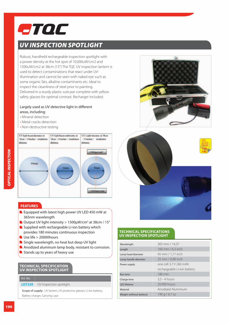
190
OPT
ICA
L IN
SPEC
TIO
N
UV INSPECTION SPOTLIGHT
Robust, handheld rechargeable inspection spotlight with
a power density at the hot spot of 10,000uW/cm2 and
1500uW/cm2 at 38cm (15”) The TQC UV inspection lantern is
used to detect contaminations that react under UV-
illumination and cannot be seen with naked eye such as
some organic fats, alkaline contaminants etc. Ideal to
inspect the cleanliness of steel prior to painting.
Delivered in a sturdy plastic suitcase complete with yellow
safety glasses for optimal contrast. Recharger included.
Largely used as UV detective light in diff erent areas, including:
Mineral detection
Metal cracks detection
Non-destructive testing
FEATURES
Equipped with latest high power UV LED 450 mW at 365nm wavelength Output UV light intensity > 1500μW/cm2 at 38cm / 15” Supplied with rechargeable Li-ion battery which provides 180 minutes continuous inspection Use life > 20000hours Single wavelength, no heat but deep UV light Anodized aluminum lamp body, resistant to corrosion. Stands up to years of heavy use
TECHNICAL SPECIFICATION UV INSPECTION SPOTLIGHT
Art. No
LD7220 UV Inspection spotlight
Scope of supply: UV lantern, UV protective glasses, Li-ion battery,
Battery charger, Carrying case
TECHNICAL SPECIFICATIONS UV INSPECTION SPOTLIGHT
Wavelength 365 mm / 14,37
Length 160 mm / 6,3 inch
Lamp head diameter 45 mm / 1,77 inch
Lamp handle diameter 25 mm / 0,98 inch
Power supply one cell 3,7 V 260 mAh
rechargeable Li-ion battery
Run time 180 min
Charge time 3,5 - 4 hours
LED lifetime 20.000 hours
Material Anodized Aluminium
Weight (without battery) 190 g / 6,7 oz
SEE ALSOPAGE139-140

191
OPTICA
L INSPECTIO
N
INSPECTION MIRROR TELE-SCOPIC (ANTENNA-TYPE) - ROUND Perfect tool to use for inspection of professional coating
jobs on large structures, ships, tanks, buildings etc.
The inspection mirrors offers a clear view on hard-to-reach
places and ideal for a visual inspection for “holy-days” and
general quality control for matters as coverage, cleanliness
of blasted steel etc
FEATURES
With telescopic handle Pocket size
ORDERING INFORMATION INSPECTION MIRROR TELESCOPIC (ANTENNA-TYPE) - ROUND
Art. No LD3004 LD3025
Diameter mirror 31 mm / 1,22 inch 56 mm / 2,2 inch
Min Length 130 mm / 5,12 inch 254 mm / 10 inch
Max Length 455 mm / 17,19 inch 375 mm / 14,76 inch
Material Glass/ Glass/
Nickel plated steel Nickel plated steel
Weight 40 g / 1,41 oz. 100 g / 3,53 oz.
Scope of supply: Round Inspection mirror telescopic (Antenna-type)
LD3025LD3004
UV POCKET FLASHLIGHT
Small, light weight, UV pocket flashlight powered by an
ultra-high output 390-410nm UV LED. This TQC UV pocket
flashlight is used to detect contaminations that react
under UV-illumination and cannot be seen with naked
eye such as some
organic fats,
alkaline
contaminants
etc.. Ideal to in-
spect the cleanli-
ness of steel prior
to painting.
FEATURES
LED Bulb free Aluminium casing Waterproof and shockproof housing Light weight Dynamic switch
TECHNICAL SPECIFICATIONS UV POCKET FLASHLIGHT
Light Source LED
Chip 1x Edixeon UV LED
Batteries 3xAAA alkaline batteries
Net. weight 76 grams excl. Batteries / 2,68oz
Wavelength 395-410 NM
Beam distance 50 meters / 164ft
Burning time 170 hours
IP No. P67
Contacts Hard gold-plated contacts
Size 32x32x126mm / 1,26x1,26x4,96 inch
TECHNICAL SPECIFICATION UV POCKET FLASHLIGHT
Art. No
LD7290 UV pocket flashlight
Scope of supply: UV flashlight, Wrist strap, 3 x AAA alkaline batteries,Pouch

192
OPT
ICA
L IN
SPEC
TIO
N
COATING DEFECT IDENTIFICATION LABEL
Material Fluorescerent yellow semipermanent
adhesive with non-stick pulltab
Dimensions sticker 30x63 mm / 1,18x2,5 inch
Dimensions box 50x105x105 mm / 1,97x4,13x4,13 inch
Stickers in box 250 pieces
TECHNICAL SPECIFICATIONS COATING DEFECT IDENTIFICATION LABEL
Art. No
SP0050 TQC Coating Defect Identifi cation label, 250 pieces
Scope of supply: TQC Coating Defect Identifi cation label,
250 pieces in box
ORDERING INFORMATION COATING DEFECT IDENTIFICATION LABEL
FEATURES
Easily removable, semi-permanent stick back and non-stick pull tab No adhesives residue Writable yet water-repellent surface Hi-visible color scheme on both dark and light surfaces Illuminant yellow ink, lights up under UV light
Neutral surface for digital camera’s automatic white balancer Measuring scale clarifi es dimensions of imperfections on photographs Diameter scale shows size of pin holes, fi sh eyes etc. Writable surface to add extra information to the picture/report
Imperfections or problems found during inspections of
coating work usually require attention of second or third
parties after they have been found.
A second opinion of the paint supplier, witnessing of
counter parties or just the attention of a repair crew. In each
case it is important the above mentioned spots are easily
found back, also when the original inspector is not around
anymore.
Large structures like a ships, bridges and steel construction
but also poorly lit area’s such as tanks can cause problems
in that respect. How, for example, would you describe the
exact location of a number of small pinholes, hardly visible
(or even non-visible) with the naked eye in a 5000 square
meter tank bottom?
For recordkeeping often pictures
of the problems found are being
taken. Including the TQC CDI label
in the photograph retrieves
immediately the dimensions of
the defects and the writable area
on the label off ers the possibility
to add extra information to the
photograph.
In a serial production environment
the CDI labels can be used to
identify parts for rework or scrap.

193
CORROSION / WEATHERINGCorrosion and weathering are both major contributors to overall costs. Globally around 5 tonnes of
steel are lost every second due to corrosion. Causing huge global costs and a signifi cant infl uence
on environmental conditions. Around 30% of this staggering €17.5 billion price tag can be preven-
ted by basic corrosion testing. Not only the impact of corrosion on the environment is essential also
its infl uence on insurance costs and installation off times.
Corrosion and weathering
Corrosion and weathering have both separate causes of weather infl uences. Where corrosion often
refers to the degradation of the metal substrate or the delaminating of the paint weathering usually
is about the degradation of the coating fi lm.
Corrosion is mainly the product of humidity, an oxidizing agent and an accelerator. This accelerator
can be one of many things, examples are aggressive ions like Chlorides and sulphates, but also elec-
trical currents, are a signifi cant infl uence. The many form of corrosion all have their own background
and origin. Examples of corrosion forms are uniform, stress, pitting, bimetal corrosion.
Weathering is caused by diff erent factors, and has a milder eff ect on structural strength but a high
eff ect on visual performance. A sports car that is only shiny for the fi rst month and then loosen its
gloss and colour due to weathering. UV lights, leaching of pigments and destabilization by tempe-
rature are only some examples. Weathering is manifested by creating visual defects on the surface.
Degradation of binders and pigments are the main problem. When a binder degrades, often smaller
pigment starts to leach out. This will cause paint to loose its colour and gloss.
Types of corrosion tests
When performing a corrosion test there is a choice of multiple types of test. Neutral environments
to acidic acid, UV lighted or Cupper accelerated corrosion tests, and continuous or cyclic tests. In
order to select the right test it is important to realize what type of corrosion or weathering you are
trying to simulate. Industrial and national standards are often the biggest resource in the maze of
corrosion test standards.
CORRO
SION
/ WEATH
ERING
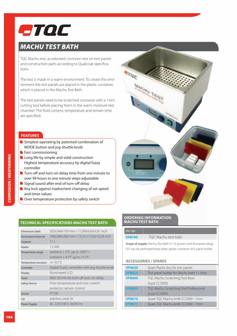
194
MACHU TEST BATH
TQC Machu test, accelerated corrosion test on test panels
and construction parts according to Qualicoat specifica-
tions.
The test is made in a warm environment. To create this envi-
ronment the test panels are placed in the plastic container,
which is placed in the Machu Test Bath.
The test panels need to be scratched crosswise with a 1mm
cutting tool before placing them in the warm moisture test
chamber. The fluid content, temperature and remain time
are specified.
FEATURES
Simplest operating by patented combination of MODE button and jog-shuttle knob Fast commissioning Long life by simple and solid construction Highest temperature accuracy by digital fuzzy controller Turn-off and turn-on delay time from one minute to over 99 hours in one minute steps adjustable Signal sound after end of turn-off delay Key lock against inadvertent changing of set speed and timer values Over temperature protection by safety switch
Dimensions Bath 302x240x150 mm / 11,89x9,45x5,91 inch
Dimensions External 338x280x260 mm / 13,31x11,02x10,24 inch
Capacity 11 l
Heater 1,2 kW
Temperature range ambient + 5°C up to 100°C /
ambient + 41°F up to 212°F
Temperature accuracy +/- 0,1°C
Controller Digital Fuzzy controller with jog-shuttle knob
Display Illuminated LCD
Timer 99hr 59 min for turn-off and -on delay
Safety Device Over temperature and over current
protector, sensor control
Sensor PT100
Lid stainless steel, lit
Power Supply AC 220/230 V, 50/60 Hz
TECHNICAL SPECIFICATIONS MACHU TEST BATH
ORDERING INFORMATIONMACHU TEST BATH
Art. No
VF8700 TQC Machu test bath
Scope of supply: Machu Test Bath (11 l), power cord (European plug),
SST top lid, perforated base plate, plastic container (4 l), panel holder
ACCESSORIES / SPARES
VF8620 Spare Plastic box for test panels
VF8625 Test panel holder for Machu bath 11 litres
VF8600 TQC Machu Scratching Tool Basic
(type CC2000)
VF8605 TQC Machu Scratching Tool Professional
(type CC3000)
VF8610 Spare TQC Machu knife CC2000 - 1mm
VF8611 Spare TQC Machu knife CC3000 - 1mm
CORR
OSI
ON
/ W
EATH
ERIN
G

195
MACHU SCRATCHING TOOL
TQC Machu Scratching Tool to perform a Machu test (cor-
rosion test) with. Each tool is provided with a 1mm width
cutter to cut the coating down to the metal, complying
with ISO 17872.
Two models are available:The TQC Machu Scratching Tool Basic is based on the
CC2000 model. with a self positioning knife bracket to
expose the substrate with a perpendicular cut through
the coating.
The TQC Machu Scratching Tool Professional is based on
the CC3000 model with adjustable cutting depth and two
ball bearings to guide the cut. This guarantees
reproducible results.
Mandatory test in Qualicoat and QIB accredited
laboratories.
FEATURES
Basic: Self aligning head to keep the cutter straight and controlled pressure to the surface Professional: Adjustable cutting depth. Two wheel bearings keep the distance to the surface always as set causing a reproducible pattern Ergonomic shaped grip Easy to replace cutter
ORDERING INFORMATION MACHU SCRATCHING TOOL
Art. No VF8600 VF8605
Model Basic (CC2000) Professional (CC3000)
Cutter 1 mm with sliding shoe 1mm with
set approx 80 mm two ball bearings
Cutting depth - adjustable
Material tool 1.2379 Vacuum 1.2379 Vacuum
hardened steel hardened steel
Material knife 55.60 Hcr 55.60 Hcr
Material handle Rubber Rubber
Dimensions 32 x1173x42 mm / 32 x1173x42 mm /
1,26x6,81x1,65 inch 1,26x6,81x1,65 inch
Weight 238 g / 8,4 oz 238 g / 8,4 oz
Scope of supply: Machu-Scratch instrument according to ISO,
1 mm cutter
ACCESSORIES / SPARES
VF8610 Spare cutter 1mm for type CC2000
VF8611 Spare cutter 1mm for type CC3000
STANDARDS
ISO 17872
VF8600
VF8605
CORRO
SION
/ WEATH
ERING

196
PH / CONDUCTIVITYAcidity and conductivity are two of the most measured parameters. From simply checking the
quality of a fi shpond to testing medicine, foodstuff or the composition of paint; Both parameters
are these days the basics of Quality control.
pH
pH is the abbreviation of Hydrogen potential in an aqueous solution. The pH scale for pH measure-
ment runs practically from 0 to 14. Pure water has a pH value of 7. Everything lower is acidic and all
higher values are basic. The acidity is caused by the detaching of a Hydrogen ion (H+) from its salt.
Basicicity is caused by the detaching of a hydrogen oxide ion (OH-) from its salt. The pH-value is a
measure of the dissolved and active amount of either H+ or OH- ions. It doesn’t directly relate to the
concentration of the acid. Inhibitors and other compounds can severely infl uence the correlation
between pH-value and acid or base concentration.
pH measurements
To measure pH there are many possibilities, from a simple pH-indicator to elaborate electrode
systems. The most commonly used pH- electrode is the Glass calomel electrode since 1906. This
type of electrode has proven its stability and reliability over many years. The electrode is most
reliable between -1 and 12. For higher basicicity other electrodes should be used. A pH-electrode is
basically an ion-selective electrode reacting to the H+ ion. This electrode is also sensitive to several
other interferences. The matrix of a sample infl uences the reliability of an electrode. Glass is also
sensitive to the presence of Fluoride ion in a solution. This aff ects the stability of the glass
membrane in the electrode. Also fi ne pigments can cause the membrane to get blocked. For
measuring in paint ISO is now working on the acceptance of ISFET electrodes for measuring the
pH-value in paint products.
Conductivity
Where pH is an ion selective method, conductivity is a non-selective method. Any salt that dissolves
into water and forms an electrolyte will result in an increase in conductivity of that sample. This
conductivity is measured in technically the same way that conductivity is measured in an electric
wire. The more dissolved salt a solution contains the better it conducts electricity. Conductivity
measurement can be infl uenced by a few parameters. One of these is static electricity that is caused
by measuring in small volumes.
PH /
CON
DU
CTIV
ITY

197
PH / CO
ND
UCTIV
ITY
CONDUCTIVITY GAUGE ECOSCAN COND 6+ KIT
Powerful portable conductivity gauge with large measuring
range. Equipped with cable electrode and integrated tem-
perature probe for automatic temperature compensation.
The high accuracy and robust protective casing make this
gauge ideal for use in the field and laboratory.
Conductivity Range .. to 19.99 uS/cm
19.9 uS/cm to 199.9 uS/cm
199.9 uS/cm to 1999 μS/cm
2.00 mS/cm to 19.99 mS/cm
20.0 mS/cm to 199.9 mS/cm
Resolution & Accuracy 0.05% full scale & +/-1% full scale + 1 LSD
Temperature Range 0 to 80.0 °C (32 to 176 °F)
Resolution & Accuracy Temp. 0.1 °C (0.1 °F) & +/-0.5 °C (+/-0.9 °F)
TECHNICAL SPECIFICATIONS PH-METER PH 6+
ORDERING INFORMATION CONDUCTIVITY GAUGE ECOSCAN COND 6+ KIT
Art. No
HI0040 Conductivity meter Ecoscan COND 6+ Kit
Scope of supply: Eutech Cond 6+ conductivity meter with electrode
ECCONSEN91B & conductivity carrying kit (includes 1 x 1413 uS,
12.88 mS, 84 uS KCl standard solution and 1x deionised (rinse) water
(60ml each)
ACCESSORIES / SPARES
HI0013 Spare pH electrode
HI0009 TQC Calibration Solution 10.01 pH, bottle of 100ml
HI0015 TQC Calibration Solution 1.68 pH, bottle of 100ml
HI0023 TQC Calibration Solution 4.01 pH, bottle of 500ml
HI0024 TQC Calibration Solution 7.00 pH, bottle of 500ml
HI0025 TQC Calibration Solution 10.01 pH,
bottle of 500ml
HI0027 TQC Calibration Solution 12880 μS,
bottle of 100ml
HI0031 TQC Calibration Solution 1413 μS, bottle of 500ml
HI0032 TQC Calibration Solution 12880 μS,
bottle of 500ml
HI0034 TQC Maintenance Storage Solution,
bottle of 100ml
HI0035 TQC Maintenance Storage Solution,
bottle of 500ml
SP7320 TQC Calibration Solution 84 μS, bottle of 50ml
SP7321 TQC Maintenance Cleansing Solution,
bottle of 50ml
FEATURES
Multi-point push-button calibration with +/-1% full scale accuracy Option of quick, easy automatic calibration or customized, near-to-sample manual calibration Auto-ranging for conductivity measurements for fast response and best resolution over wide measurement range Automatic Temperature Compensation (ATC) for the optimum accuracy under fluctuating temperatures Hold Function momentarily freezes reading for easy viewing Auto power-off saves battery power after non-use Self-Diagnostic with message codes for easy trouble shooting Large custom LCD provides optimum viewing even at a distance Electrode with built-in ATC designed for minimal air bubble entrapment during measurement Protective rubber boot shields meter from drops and features a sturdy built-in stand for easy bench-top operation
Temperature Compensation Automatic / Manual (0 to 80 °C)
Temperature Coefficient 0.0% to 3.0%
Temperature Normalisation 20.0 to 25.0 °C
No. of Calibration Points Up to 5 max. (1 per range)
Special Functions Auto Power-off after 17 minutes;
Hold & Self-diagnostic messages
Power 4 ‘AAA’ x 1.4V batteries; >100 hours
CCICALIBRATION
CERTIFICATION
INCLUDED

198
PH /
CON
DU
CTIV
ITY
PH-METER PH 5+
Easy to use, robust pH meter. Equipped with automatic
temperature compensation, buffer recognition and calibra-
tion memory. Splash proof key pad. Rubber protecting case
included as standard.
pH range 0,00 to 14,00 pH
Resolution 0,01 pH
Accuracy +/- 0,01 pH
pH slope range 80 to 120%
No of calibration pts 1-3 points (push-button)
Buffer options pH 4,01, 7,00, 10,01 (USA) pH 4,01, 6,86,
9,18 (NIST) pH 4,10, 6,97 (Pb)
Temperature Range 0,0 to 100,0°C
Resolution 0,1°C
Accuracy +/- 0,5°C
Temperature Comp. Automatic/Manual (0,0 to 100,0°C)
Material Plastic
Dimensions 1570x85x42 mm / 61,8x3,35x1,65 inch
Weight 255 g / 8,99 oz.
TECHNICAL SPECIFICATIONS PH-METER PH 5+
FEATURES
Auto-buffer recognition Hold function Auto shutt off Low battery indication 500 hours battery life
ORDERING INFORMATION PH-METER PH 5+
Art. No
HI0045 pH 5+ pH meter
Scope of supply: PH502PLUSK pH 5+ pH meter, single junction pH
electrode , ATC probe, pH carrying kit set
ACCESSORIES / SPARES
HI0013 Spare pH electrode
HI0009 TQC Calibration Solution 10.01 pH, bottle of 100ml
HI0015 TQC Calibration Solution 1.68 pH, bottle of 100ml
HI0023 TQC Calibration Solution 4.01 pH, bottle of 500ml
HI0024 TQC Calibration Solution 7.00 pH, bottle of 500ml
HI0025 TQC Calibration Solution 10.01 pH,
bottle of 500ml
HI0027 TQC Calibration Solution 12880 μS,
bottle of 100ml
HI0031 TQC Calibration Solution 1413 μS, bottle of 500ml
HI0032 TQC Calibration Solution 12880 μS,
bottle of 500ml
HI0034 TQC Maintenance Storage Solution,
bottle of 100ml
HI0035 TQC Maintenance Storage Solution,
bottle of 500ml
SP7320 TQC Calibration Solution 84 μS, bottle of 50ml
SP7321 TQC Maintenance Cleansing Solution,
bottle of 50ml
CCICALIBRATION
CERTIFICATION
INCLUDED

199
PH / CO
ND
UCTIV
ITY
Display LCD
Salinity Range 1 to 50.0 ppt; 0.1 to 5.00 %
Resolution 0.1 ppt; 0.01%
Accuracy +/-1% Full Scale
TDS Factor Non-linear compensation
Temperature Range 0 to 100.0 °C
Temperature Resolution & Accuracy 0.1 °C & +/- 0.5 °C
Temperature Compensation Automatic / Manual (0 to 80 °C)
Temperature Coeffi cient 2%/°C
No. of Calibration Points 1 point
Power Supply 4 ‘AAA’ x 1.4V batteries
Size Meter 140 x 70 x 35 mm
Weight Meter 200 g
Size total kit 170 x 350 x 75 mm
Weight total kit 1700 g
TECHNICAL SPECIFICATIONS PALMTOP SALINITY METER ECOSCAN SALT 6
PALMTOP SALINITY METER ECOSCAN SALT 6
Palmtop salinity meter EcoScan Salt TDS6 in kit for quick,
accurate salinity measurementsBresle KIT. A protective rub-
ber boot shields the meter fram drops and features a sturdy
built-in stand for easy bench top operation.
ORDERING INFORMATION PALMTOP SALINITY METER ECOSCAN SALT 6
Art. No
HI0050 Palmtop salinity meter Ecoscan salt 6
TDS6/03K EcoScan TDS 6 in kit
Scope of supply: EcoScan SALT 6 Palmtop Salinity Meter with
electrode (EC-CONSEN91B) and Salinity carrying kit set
ACCESSORIES / SPARES
HI0013 Spare pH electrode
HI0009 TQC Calibration Solution 10.01 pH, bottle of 100ml
HI0015 TQC Calibration Solution 1.68 pH, bottle of 100ml
HI0023 TQC Calibration Solution 4.01 pH, bottle of 500ml
HI0024 TQC Calibration Solution 7.00 pH, bottle of 500ml
HI0025 TQC Calibration Solution 10.01 pH,
bottle of 500ml
HI0027 TQC Calibration Solution 12880 μS,
bottle of 100ml
HI0031 TQC Calibration Solution 1413 μS, bottle of 500ml
HI0032 TQC Calibration Solution 12880 μS,
bottle of 500ml
HI0034 TQC Maintenance Storage Solution,
bottle of 100ml
HI0035 TQC Maintenance Storage Solution,
bottle of 500ml
SP7320 TQC Calibration Solution 84 μS, bottle of 50ml
SP7321 TQC Maintenance Cleansing Solution,
bottle of 50ml
CCICALIBRATION
CERTIFICATION
INCLUDED
FEATURES
Push-button calibration with +/-1% full scale accuracy. Automatic Temperature Compensation (ATC) for the optimum accuracy under fl uctuating temperatures. Self-diagnosis with message codes for easy trouble- shooting. Electrode with built-in ATC designed for minimal air bubble entrapment during measurement. Low battery indication Auto power-off after 17 minutes Special functions: hold; self-diagnostic messages Protective rubber boot Sturdy built-in stand for easy bench-top operation.

200
PH /
CON
DU
CTIV
ITY
CONDUCTIVITY METER
The TQC Conductivity Meter now measures a wider
conductivity range from pure water to waste water and
and comes with simultaneous temperature display, auto-
ranging capabilities. Signature designs such as automatic
temperature compensation and manual calibrations are
retained, giving you accurate, reliable readings over a
broad conductivity range every time you measure.
The TQC Conductivity Meter is rugged and waterproof to
IP67 standards and is a standard item in the TQC Bresle KIT.
TECHNICAL SPECIFICATIONS CONDUCTIVITY METER
Range 0 to 200.0 uS/cm
0 to 2000 uS/cm,
0 to 20.00 mS/cm
Resolution 0.1 uS/cm; 1 uS/cm 0.01 mS/cm
Accuracy +/- 1% Full scale
Calibration Points (Auto) 3 (84,0 uS/cm, 1413 uS/cm,
12,88 mS/cm)
(Manual) 3 (One per range)
Temperature Display Yes
Operating Temperature 0 to 50 °C / 32 to 122oF
ATC 0 to 50 °C / 32 to 122oF
Temperature Coefficient 2% per °C / 77.0oF
Normalization Temperature 25.0 °C
Auto-Off 8.5 Minutes after last key pressed
Non-Volatile Memory Yes
Power 4 x 1.5 V “A76” Micro alkaline battery
> 150 Hours
LCD Display Custom dual display
27 mm x 21 mm / 1,06 x 0,8 inch
Dimensions 1650x38 mm / 65x1,5 inch
Weight 90 g / 31,8 oz.
Dimensions Boxed 2200x60x50 mm / 86,6x2,36x1,97 inch
Weight Boxed 170 g / 6 oz.
ORDERING INFORMATION CONDUCTIVITY METER
Art. No
HI0017 TQC Conductivity Meter waterproof
Multi Range Tester
Scope of supply: TQC Conductivity Meter
ACCESSORIES / SPARES
HI0013 Spare pH electrode
HI0009 TQC Calibration Solution 10.01 pH, bottle of 100ml
HI0015 TQC Calibration Solution 1.68 pH, bottle of 100ml
HI0023 TQC Calibration Solution 4.01 pH, bottle of 500ml
HI0024 TQC Calibration Solution 7.00 pH, bottle of 500ml
HI0025 TQC Calibration Solution 10.01 pH,
bottle of 500ml
HI0027 TQC Calibration Solution 12880 μS,
bottle of 100ml
HI0031 TQC Calibration Solution 1413 μS, bottle of 500ml
HI0032 TQC Calibration Solution 12880 μS,
bottle of 500ml
HI0034 TQC Maintenance Storage Solution,
bottle of 100ml
HI0035 TQC Maintenance Storage Solution,
bottle of 500ml
SP7320 TQC Calibration Solution 84 μS, bottle of 50ml
SP7321 TQC Maintenance Cleansing Solution,
bottle of 50ml
HI0055 Spare probe for the ECTestr11+
CCICALIBRATION
CERTIFICATION
INCLUDED
FEATURES
+/- 1% full scale accuracy Automatic temperature compensation (ATC) User friendly Easy-to-read large display Rugged waterproof anti-roll design User-replaceable sensors Innovative Sensor housing design Auto Power-Off oC / oF

201
PH-METER PH TESTR 10 (WATERPROOF)Easy-to-use, fully waterproof, pH meter with large display.
Floats. The modular design makes it extremely easy to
change electrodes. The PH meter is equipped with auto-
matic calibration with buffer recognition. The accuracy of
the meter is 0,1 Ph. With automatic temperature compen-
sation.
ORDERING INFORMATION PH-METER PH TESTR 10
Art. No
HI0019 PHTEST10 Waterproof pHTestr10
Scope of supply: PHTEST10 Waterproof pHTestr10
ACCESSORIES / SPARES
HI0013 Spare pH electrode
HI0009 TQC Calibration Solution 10.01 pH, bottle of 100ml
HI0015 TQC Calibration Solution 1.68 pH, bottle of 100ml
HI0023 TQC Calibration Solution 4.01 pH, bottle of 500ml
HI0024 TQC Calibration Solution 7.00 pH, bottle of 500ml
HI0025 TQC Calibration Solution 10.01 pH,
bottle of 500ml
HI0027 TQC Calibration Solution 12880 μS,
bottle of 100ml
HI0031 TQC Calibration Solution 1413 μS, bottle of 500ml
HI0032 TQC Calibration Solution 12880 μS,
bottle of 500ml
HI0034 TQC Maintenance Storage Solution,
bottle of 100ml
HI0035 TQC Maintenance Storage Solution,
bottle of 500ml
SP7320 TQC Calibration Solution 84 μS, bottle of 50ml
SP7321 TQC Maintenance Cleansing Solution,
bottle of 50ml
TECHNICAL SPECIFICATIONS PH-METER PH TESTR 10
pH Range -1.0 to 15.0
Resolution 0.1 pH
Relative Accuracy +/-0.1
Calibration Up to 3 points Yes
Calibration Buffer option USA- 4.01/7.00/10.01
NIST- 4.01/6.86/9.18
Automatic Temperature Compensation (ATC) Yes
Sensor Double-junction, Ag/AgCl system
with polymer gel
Auto Off After 8.5 minutes from last key press
User reset Yes
Non Volatile Memory Backup Yes
LCD Display Dual
Power Requirement 4 x 1.5V “A 76” micro
Alkaline Batteries
Battery life More than 500 hrs
Operating Temperature 0-50 °C / 32-122 °F
Dimensions 1650x38 mm / 65x1,5 inch
Weight 90 g / 31,8 oz.
Dimensions Boxed 2200x60x50 mm /
86,6x2,36x1,97 inch
Weight Boxed 170 g / 6 oz.
PH / CO
ND
UCTIV
ITY
CCICALIBRATION
CERTIFICATION
INCLUDED
FEATURES
Waterproof Large display screen Up to +/-0.01 pH accuracy Microprocessor Based User replaceable double junction, polymer sensor 3-point (USA or NIST) push button calibration with buffer recognition Simultaneous temperature Display in °C or °F (pH Tester 30) Automatic temperature compensation Self-diagnostic messages Non-volatile memory Hold and auto-off functions

202
PH /
CON
DU
CTIV
ITY
FEATURES
Waterproof Auto-off after 8 minutes The EC/TDS conversion factor is user selectable as is the temperature compensation coefficient (ß) Fast, efficient, accurate and portable
TECHNICAL SPECIFICATIONS COMBOTESTER PH EC TDS TEMPERATURE
Display Dual-level LCD
Range pH 0.00 to 14.00
EC 0.00 to 20.00 mS/cm
TDS 0.00 to 10.00 ppt
Temperature 0.0 to 60.0°C
Resolution 0.01 pH
0.01mS / cm EC
0.01 ppt TDS
0.1°C
Accuracy +/-0.05 pH
+/-2% F.S. EC/TDS
+/-0.5°C
Calibration pH Automatic
EC/TDS Automatic
Power Supply 4x 1.5V
Size 163 x 40 x 26 mm
Weight Meter 85 g
ORDERING INFORMATION COMBOTESTER PH EC TDS TEMPERATURE
Art. No
HI9813 Combo tester
Scope of supply: Combo tester with manual
ACCESSORIES / SPARES
HI0013 Spare pH electrode
HI0009 TQC Calibration Solution 10.01 pH, bottle of 100ml
HI0015 TQC Calibration Solution 1.68 pH, bottle of 100ml
HI0023 TQC Calibration Solution 4.01 pH, bottle of 500ml
HI0024 TQC Calibration Solution 7.00 pH, bottle of 500ml
HI0025 TQC Calibration Solution 10.01 pH,
bottle of 500ml
HI0027 TQC Calibration Solution 12880 μS,
bottle of 100ml
HI0031 TQC Calibration Solution 1413 μS, bottle of 500ml
HI0032 TQC Calibration Solution 12880 μS,
bottle of 500ml
HI0034 TQC Maintenance Storage Solution,
bottle of 100ml
HI0035 TQC Maintenance Storage Solution,
bottle of 500ml
SP7320 TQC Calibration Solution 84 μS, bottle of 50ml
SP7321 TQC Maintenance Cleansing Solution,
bottle of 50ml
COMBOTESTER PH EC TDS EMPERATURE (WATERPROOF)
This Combo waterproof tester offers high accuracy pH,
EC/TDS and temperature measurements in a single tester.
pH and EC/TDS readings are automatically compensated
for the effects of temperature (ATC).
This technologically advanced tester has a replaceable pH
electrode cartridge with an extendable cloth junction as
well as an EC/TDS graphite electrode that resists con-
tamination by salts and other substances. This gives these
meters a greatly extended life. Your tester no longer needs
to be thrown away when the pH sensor is exhausted.

203
PH / CO
ND
UCTIV
ITY
ORDERING INFORMATION CALIBRATION AND MAINTENANCE SOLUTION
Art No Type pH / μS ml
HI0009 Calibration Solution 10.01 pH bottle of 100ml
HI0015 Calibration Solution 1.68 pH bottle of 100ml
HI0023 Calibration Solution 4.01 pH bottle of 500ml
HI0024 Calibration Solution 7.00 pH bottle of 500ml
HI0025 Calibration Solution 10.01 pH bottle of 500ml
SP7320 Calibration Solution 84 μS bottle of 50ml
HI0027 Calibration Solution 12880 μS bottle of 100ml
HI0031 Calibration Solution 1413 μS bottle of 500ml
HI0032 Calibration Solution 12880 μS bottle of 500ml
HI0034 Maintenance Storage
Solution bottle of 100ml
HI0035 Maintenance Storage bottle of 500ml
Solution
SP7321 Maintenance bottle of 50ml
Cleansing Solution
TQC Calibration and Maintenance Solutions are essential
for calibrating and maintaining the pH and/or conducti-
vity gauge. A wide range of liquid measuring systems is
available, in addition to acidity (pH), conductivity (S) and
temperature (T), we also have instruments measuring levels
of dissolved oxygen and TDS (Total Dissolved Solids), as
well as Ion-selective meters. Portable versions and desktop
models for use in laboratories.
CALIBRATION AND MAIN-TENANCE SOLUTION (WATERPROOF)
ORDERING INFORMATION PH INDICATOR PAPER UNIVERSAL - PH 1-14
Art. no
SP2000 Universal PH indicator paper
Indicator paper on a roll for acid and base (alkaline) test.
PH INDICATOR PAPER UNIVERSAL - PH 1-14
Range 1-14 pH
Length 5 m
TECHNICAL SPECIFICATIONS PH INDICATOR PAPER UNIVERSAL - PH 1-14
FEATURES
Fast response time within a minute
Easy to read, accurate color charts
High contrast for easy color chart comparisons

204
PH /
CON
DU
CTIV
ITY
Art. No
HI0022 CyberScan PC 10 Meter
ORDERING INFORMATION CYBERSCAN PC 10 METER
PH CONDUCTIVITY-METER CYBERSCAN PC10
Extremely handy gauge for determining pH (acidity),
conductivity and temperature of liquids. The diff erent
probes are combined in a waterproor casing, equipped
with a 3-meter long waterproof cable. Large display shows
various parameters simultaneously.
TECHNICAL SPECIFICATIONS CYBERSCAN PC 10 METER
pH Range 0.00 to 14.00 pH
Resolution 0.01 pH
Accuracy +/-0.01 pH
Calibration Up to 3 points
(pH 4.01, 7.00, 10.01) with
automatic buff er
recognition
Conductivity Range 0 to 19.99, 199.9, 1999 μS/cm
0 to 19.99 mS/cm
Resolution 0.01, 0.1, 1 μS/cm
0.01 mS/cm
Accuracy +/-1% Full scale +1 digit
Calibration Up to 4 points (1 point per range)
Temperature Range 0.0 to 100.0 oC
Resolution 0.1 oC
Accuracy +/- 0.5 oC
Calibration Off set in 0.1 oC increments
Conductivity 1.0
Cell Constant (k)
Conductivity Temperature 2.00% per oC
Temperature Automatic from 0 to 50 oC
Compensation
Operating Temperature 0 to 50 oC
Power Requirements 4 ’AAA’ Batteries
AC/DC Adapter 9V, 500 mA
Battery Life > 50 hours
Dimension / Weight Meter 18 x 9 x 4cm ; 220g
Boxed 24 x 23 x 7cm ; 600g
Probe 19 x 5cm, with 3-metre cable
CCICALIBRATION
CERTIFICATION
INCLUDED
FEATURES
Microprocessor based pH/Conductivity/ °C meter
High accuracy
Easy push-button calibration
Single-button switch between pH & conductivity
Rugged multi-parameter submersible probe

205
PUB
LICATION
S
PUBLICATIONS AND STANDARDSTo make application of coatings successful, knowledge of methods and products play an important
role. Information about preparation, methods, and measuring equipment can be obtained by read-
ing a variety of standards and publications.
Standards and publications are identifi ed and described by various bodies such as ISO, DIN, ASTM,
BS, SSPC and many other organizations. The information is provided as a certifi cate, standard maga-
zine, book, data sheet or documentation
Measuring or testing methods are often defi ned according to previously determined conditions.
As an example, there is the ISO 2808 which describes the various possibilities for dry fi lm thickness
measurement, or similar ASTM D 7091 or ASTM B 224.
Preparation of surfaces by means of blasting can be found in the ISO 8501, Swedish standard SIS-,
or in the SSPC-VIS / VIS NACE guides which are provided with clear images for comparison to the
surface treated.

206
A guide to assist ship’s staff in the
assessment of tank, hold and
space coatings of existing ships
for the purpose of determining
compliance with the Rules and
Regulations for the Classifi cation
of Ships. The guide handles the
defi nition of the tank coating
condition in Good / Fair / Poor
classifi cation. It also contains the
IACS methodology to divide tanks
into a number of smaller “areas under consideration” which
can easily be identifi ed. Further are included schematics to
help defi ning area determination, percentage of coatings
breakdown for specifi c ship structures and a comparison
of common rust scales. A series of full color pictures of tank
coatings in various conditions and a section that describes
and shows the hotspots for corrosion and other common
defects is also part of the guide.
The last section contains sketched indicating common
nomenclature and terminology applied to typical
structure of major ship types.
TANK COATINGS CONDITION GUIDE
TECHNICAL SPECIFICATIONS TANK COATINGS CONDITION GUIDE
Papersize 135x95 mm / 5,3x3,7 inch
No pages 110
Binding spiral
ORDERING INFORMATION TANK COATINGS CONDITION GUIDE
Art. No
LD3075 Tank Coatings Condition Guide
FITZ S ATLAS 2 OF COATING DEFECTSThe Fitz’s Atlas 2 of coating defects is a reference manual
with over 300 colour images, providing a clear and con-
cise description of all problems that could occur, as well as
their possible causes.
The book is divided into the following sections:
Welding faults
Presurface conditions
Coating defects
Microscopy
Marine fouling
TECHNICAL SPECIFICATIONS FITZ S ATLAS 2 OF COATING
Paper size 120x190 mm / 4,75x7,5 inch
No pages 200
Binding ring binder
Over 300 colour pictures
ORDERING INFORMATION FITZ S ATLAS 2 OF COATING
Art. No
LD3061 Fitz’s Atlas 2 of coating defects
PUB
LICA
TIO
NS
SEE ALSOPAGE162-165

207
THE PAINT INSPECTOR’S FIELD GUIDE
The Inspection of protective coating systems for corro-
sion control includes a wide range of test methods and
techniques. In the Paint Inspector’s Field Guide( PIFG ) a
wide range of these inspection methods are covered in
an eff ort to aid individuals with the basic fundamentals of
protective coating inspection whilst in the fi eld.
Lee Wilson, who is a highly qualifi ed and well respected
inspector with many years of fi eld experience, provides an
excellent description of the actions performed by an in-
spector and the tools they use. The Paint Inspector’s Field
Guide covers all aspects from specifi cation review and
surface preparation works all the way through to applica-
tion and fi nal reporting.
The Paint Inspector’s Field Guide is complemented by a
wide range of inspection and experience notes making it
easy to solve those special problems which are commonly
encountered in the fi eld. Besides the textual support, the
rich graphics provide clear visual reference to inspection
techniques, standards and defects. The years of experi-
ence and the editing by Brian Goldie makes the Paint
Inspector’s Field Guide a pleasure to read and the best
reference book available.
The Paint Inspector’s Field Guide is a must have tool for
any individual involved or interested in corrosion control
by protective coatings and the inspections required to
achieve this.
FEATURES
Wide range of inspection and experience notes Rich graphics provide clear visual reference to inspection techniques, standards and defects
TECHNICAL SPECIFICATIONS THE PAINT INSPECTORS
Papersize 120 x 180 mm / 4,72 x 7,09 inch
No pages 198
Binding wire-o-binding
Price 110.- EUR ex. works
ORDERING INFORMATION THE PAINT INSPECTORS
Art. No
LD3080 The Paint Inspector’s Field Guide
PUB
LICATION
S

208
ORDERING INFORMATION ISO HANDBOOKS PAINTS & VARNISHES
Art. No
LD3015 Paint & Varnishes Vol 1. General test methods part 1
LD3019 Paint & Varnishes Vol 1. General test methods part 2
LD3016 Paint & Varnishes part 2. Raw materials
LD3017 Paint & Varnishes part 3. Preparation and protection of steel substrates
TECHNICAL SPECIFICATIONS ISO HANDBOOKS PAINTS & VARNISHES
Art. No LD3015 LD3019 LD3016 LD3017
Binding Glued Glued Glued Glued
Colour Black/White Black/White Black/White Black/White
Images Yes Yes Yes Yes
Pages 1056 1062 552 1036
Dimensions 210 x 150 x 24 mm / 210 x 150 x 24 mm / 210 x 150 x 23 mm / 210 x 150 x 33 mm /
8,27 x 5,91 x 0,94 inch 8,27 x 5,91 x 0,94 inch 8,27 x 5,91 x 0,91 inch 8,27 x 5,91 x 1,3 inch
Weight 690 g / 24,3 oz. 690 g / 24,3 oz. 680 g / 24 oz. 990 g / 34,9 oz.
PUB
LICA
TIO
NS
ISO HANDBOOKS PAINTS & VARNISHES
A collection of more than 280 ISO International Standards
covering the best methods for performance of paints and
varnishes, as well as for the main groups of raw materials
used in their manufacture. Standards for terminology and
preparation and protection of steel substrates. Bound into
four volumes.
All standards are written in English language. Pictures are
printed in black and white.
SEE ALSOPAGE162-165

209
MISCELLANEOUSA lot of instruments used in this chapter and in the fi eld of
coatings are not direct related to a specifi c paint job or
coating product but still of interest for improved and saver
work in this type of industry where coatings are applied.
Some instruments are specifi cally developed for architec-
tural and paint advising consultants who has to calculate
spatial volumes or heights.
Others are needed to protect the painter against toxic or
fl ammable gasses in polluted or poisening areas by using a
personal alarm.
To get well organized and to have the equipment ready for
use at hand cases in diff erent sizes and protecting classes
are available on request.
We hope you fi nd that particular part out of our list or just
ask us for more.
MISCELLA
NEO
US
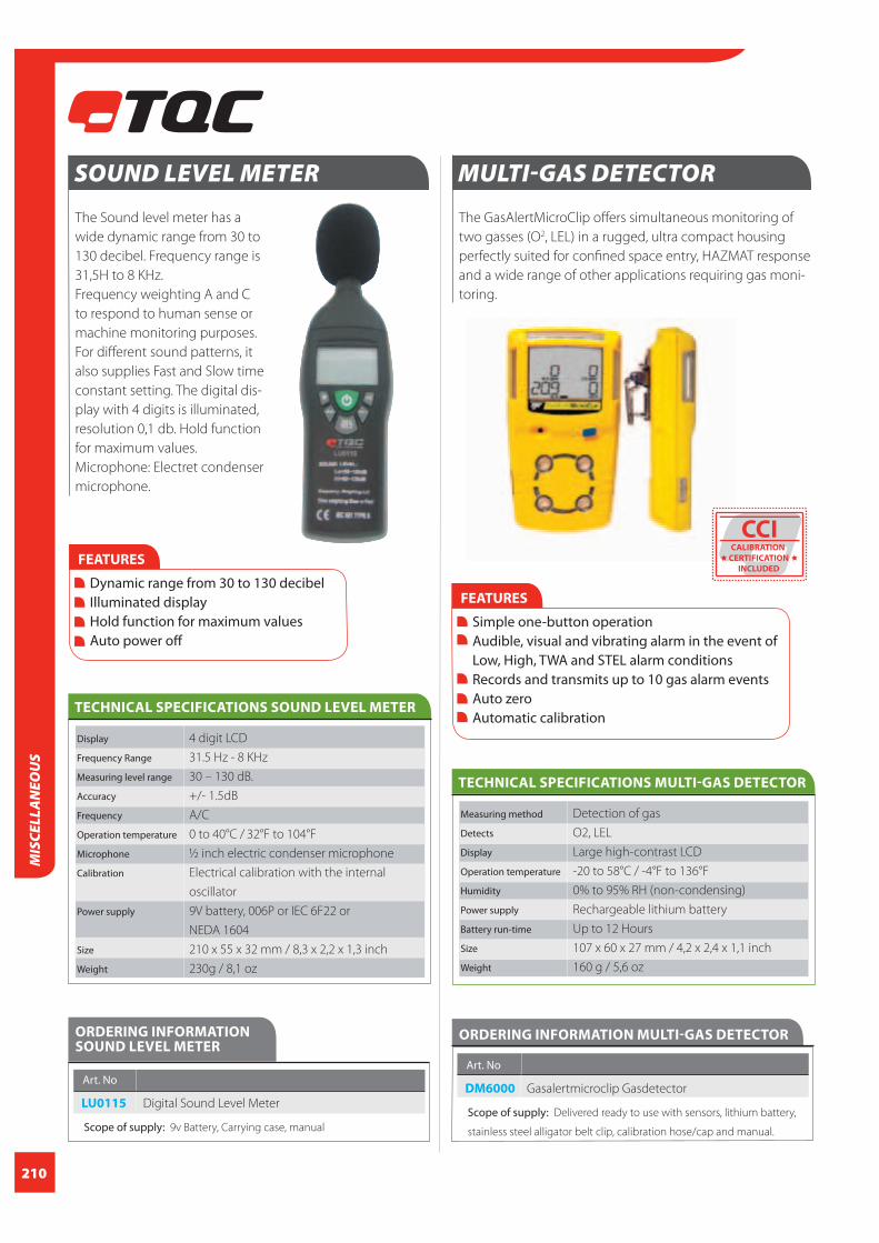
210
MIS
CELL
AN
EOU
S
SOUND LEVEL METER
The Sound level meter has a
wide dynamic range from 30 to
130 decibel. Frequency range is
31,5H to 8 KHz.
Frequency weighting A and C
to respond to human sense or
machine monitoring purposes.
For different sound patterns, it
also supplies Fast and Slow time
constant setting. The digital dis-
play with 4 digits is illuminated,
resolution 0,1 db. Hold function
for maximum values.
Microphone: Electret condenser
microphone.
TECHNICAL SPECIFICATIONS SOUND LEVEL METER
Display 4 digit LCD
Frequency Range 31.5 Hz - 8 KHz
Measuring level range 30 – 130 dB.
Accuracy +/- 1.5dB
Frequency A/C
Operation temperature 0 to 40°C / 32°F to 104°F
Microphone ½ inch electric condenser microphone
Calibration Electrical calibration with the internal
oscillator
Power supply 9V battery, 006P or IEC 6F22 or
NEDA 1604
Size 210 x 55 x 32 mm / 8,3 x 2,2 x 1,3 inch
Weight 230g / 8,1 oz
ORDERING INFORMATION SOUND LEVEL METER
Art. No
LU0115 Digital Sound Level Meter
Scope of supply: 9v Battery, Carrying case, manual
FEATURES
Dynamic range from 30 to 130 decibel Illuminated display Hold function for maximum values Auto power off
MULTI-GAS DETECTOR
The GasAlertMicroClip offers simultaneous monitoring of
two gasses (O2, LEL) in a rugged, ultra compact housing
perfectly suited for confined space entry, HAZMAT response
and a wide range of other applications requiring gas moni-
toring.
TECHNICAL SPECIFICATIONS MULTI-GAS DETECTOR
Measuring method Detection of gas
Detects O2, LEL
Display Large high-contrast LCD
Operation temperature -20 to 58°C / -4°F to 136°F
Humidity 0% to 95% RH (non-condensing)
Power supply Rechargeable lithium battery
Battery run-time Up to 12 Hours
Size 107 x 60 x 27 mm / 4,2 x 2,4 x 1,1 inch
Weight 160 g / 5,6 oz
FEATURES
Simple one-button operation Audible, visual and vibrating alarm in the event of Low, High, TWA and STEL alarm conditions Records and transmits up to 10 gas alarm events Auto zero Automatic calibration
ORDERING INFORMATION MULTI-GAS DETECTOR
Art. No
DM6000 Gasalertmicroclip Gasdetector
Scope of supply: Delivered ready to use with sensors, lithium battery,
stainless steel alligator belt clip, calibration hose/cap and manual.
CCICALIBRATION
CERTIFICATION
INCLUDED

211
MISCELLA
NEO
US
SINGLE-GAS DETECTOR 2 YEAR VERSION
The GasAlertClipExtreme Oxygen (O2) offers continuous,
reliable protection.
ORDERING INFORMATION SINGLE-GAS DETECTOR 2 YEAR VERSION
Art. No
DM6010 Single-Gas Detector 2 Year Version
Scope of supply: Delivered ready to use with sensors, stainless steel
alligator belt clip and concussion proof housing, test cap and manual.
FEATURES
Audible, visual and vibrating alarm in the event of Low and High Auto zero Automatic calibration No battery replacement or battery charging required. 2 year version: 2 years of continuous maintenance- free protection
Measuring method Detection
Display Large high-contrast LCD
Operation temperature -20 to 50°C / -4°F to 122°F
Humidity: 0% to 95% RH (non-condensing)
Size 28 x 50 x 81 mm / 1,1 x 2 x 3,2 inch
Weight 76 g / 2,7 oz
TECHNICAL SPECIFICATIONS SINGLE-GAS DETECTOR 2 YEAR VERSION
The TQC Analytical Balance
Mark 124A is a top quality
weighing scale that
combines elegance with
highly reliable measuring
performance. The accu-
racy and range perfectly
matches the specifications
of the machu test that is
a mandatory test in
Qualicoat, QIB and GSB
accredited laboratories.
ANALYTICAL BALANCE MARK 124A
FEATURES
Selectable filter level Selectable measure units Piece counting function Calibration weight Serial interface RS232
TECHNICAL SPECIFICATIONSANALYTICAL BALANCE MARK 124A
Measuring method Balance
Display LCD display with backlight
Weighing capacity 120 g / 4,2 oz
Readability 0.1 mg
Reproducibility (standard deviation) 0.1 mg
Linearity +/- 0.3 mg
Sensitivity drift (10...30 °C) +/- 3 ppm / °C
Auto zero ON-OFF from Menu
Pan size 80mm
Housing dimensions (W x D x H) 205 x 325 x 315 mm /
8,1 x 12,8 x 12,4 inch
Net weight 7400 g / 16,31 Lbs
Calibration weight 100 g (E2) / 3,5 oz
ORDERING INFORMATION ANALYTICAL BALANCE MARK 124A Art. No
DI7050 Analytical Balance Mark 124A
Scope of supply: Balance, Adapter and Manual
CCICALIBRATION
CERTIFICATION
INCLUDED
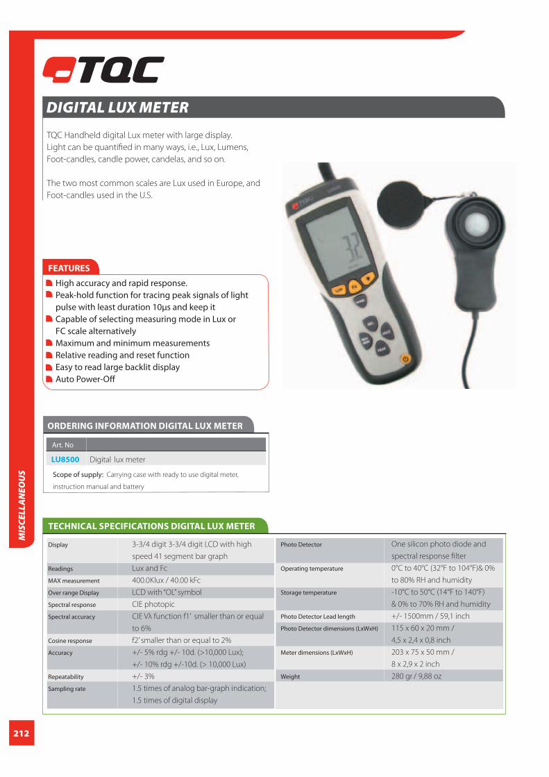
212
MIS
CELL
AN
EOU
S
DIGITAL LUX METER
TQC Handheld digital Lux meter with large display.
Light can be quantified in many ways, i.e., Lux, Lumens,
Foot-candles, candle power, candelas, and so on.
The two most common scales are Lux used in Europe, and
Foot-candles used in the U.S.
FEATURES
High accuracy and rapid response. Peak-hold function for tracing peak signals of light pulse with least duration 10μs and keep it Capable of selecting measuring mode in Lux or FC scale alternatively Maximum and minimum measurements Relative reading and reset function Easy to read large backlit display Auto Power-Off
TECHNICAL SPECIFICATIONS DIGITAL LUX METER
Photo Detector One silicon photo diode and
spectral response filter
Operating temperature 0°C to 40°C (32°F to 104°F)& 0%
to 80% RH and humidity
Storage temperature -10°C to 50°C (14°F to 140°F)
& 0% to 70% RH and humidity
Photo Detector Lead length +/- 1500mm / 59,1 inch
Photo Detector dimensions (LxWxH) 115 x 60 x 20 mm /
4,5 x 2,4 x 0,8 inch
Meter dimensions (LxWxH) 203 x 75 x 50 mm /
8 x 2,9 x 2 inch
Weight 280 gr / 9,88 oz
Display 3-3/4 digit 3-3/4 digit LCD with high
speed 41 segment bar graph
Readings Lux and Fc
MAX measurement 400.0Klux / 40.00 kFc
Over range Display LCD with “OL” symbol
Spectral response CIE photopic
Spectral accuracy CIE Vλ function f1’ smaller than or equal
to 6%
Cosine response f2’ smaller than or equal to 2%
Accuracy +/- 5% rdg +/- 10d. (>10,000 Lux);
+/- 10% rdg +/-10d. (> 10,000 Lux)
Repeatability +/- 3%
Sampling rate 1.5 times of analog bar-graph indication;
1.5 times of digital display
ORDERING INFORMATION DIGITAL LUX METER
Art. No
LU8500 Digital lux meter
Scope of supply: Carrying case with ready to use digital meter,
instruction manual and battery

213
MISCELLA
NEO
US
SPRAYSHOP ANALYSER
Complete measuring set for checking electrostatic (powder)
lacquer coating installations. Both the earth of the object as
the spray tip voltage can be measured. Proper inspection of
the spraying installation improves the quality of the coating
work and reduces over-
spraying. Complete with
3GÙ HT probe without
temperature measurement.
FEATURES
Audible signal for earth / ground detection Digital high voltage meter Digital thermometer Auto power down backlight Auto power-off
ORDERING INFORMATION SPRAYSHOP ANALYSER
Art. No
LD0080 Sprayshop meter
Scope of supply: Instrument comes in a protective case including
surface temperature probe, 3GÙ HT probe, Continuity test leads and
manual.
RESISTIVITY METER
Simple instrument for measuring the surface resistivity of
electrostatically sprayed coatings. The probe is easy to clean
and is immersed in the coating. The measured value
is recorded on an analogue scale.
FEATURES
Scale in Ohmic Values – 10K – 5 mega ohms Simple scale identifying electrostatic sprayability Easy to clean probe Built-in battery test
TECHNICAL SPECIFICATIONS RESISTIVITY ANALYSER
Scale Ohmic values
Power supply 2x PP3 Battery
Weight 1500 g / 52,9 oz
ORDERING INFORMATION RESISTIVITY ANALYSER
Art. No
LD0085 Resisivity Gauge, incl probe and case
Scope of supply: Instrument comes in a protective case with manual.
TECHNICAL SPECIFICATIONS SPRAYSHOP ANALYSER
Display LCD
High voltage measurement range 1.0kv to 150 kV
Accuracy 3%
Resolution 100V
Leakage resistance Up to 30GΩ
Temperature measurement range 0° to 1250°C / 32°F to 228,2 °F
Accuracy +/- 3%
Resolution 1°C
Power supply 9V PP3
Size 170 x 82 x 30 mm /
6,7 x 3,2 x 1,2 inch
Weight 330 g / 11,64 oz
CCICALIBRATION
CERTIFICATION
INCLUDED

214
MIS
CELL
AN
EOU
S
FEATURES
Inside Auto scaling Readout is displayed in Mega ohm (M). Low battery indicator Easy to clean probe
STANDARDS
ASTM D 5682
ORDERING INFORMATION DIGITAL RESISTIVITY METER FOR COATINGS
Art. No
LD5950 Digital resistivity meter for coatings
Scope of supply: Instrument comes in a protective case including
verifi cation certifi cate and manual.
TECHNICAL SPECIFICATIONS DIGITAL RESISTIVITY METER FOR COATINGS
Display LCD
Range 100 Kohm – 20.000 Kohm (20 Mohm)
Precision 0.1 – 0.5 M = 3%
0.5 – 5.0 M = 1 %
5.0 – 10.0 M = 2 %
10.0 – 20.0 M = 3%
Measuring signal 45 v
Power supply 1 x 9 v battery
Size 100 x 200 x 30 mm / 3,9 x 7,9 x 1,2 inch
Probe size 230 mm O 42 mm / 9,1 inch O 1,7 inch
Weight 280 g
CCICALIBRATION
CERTIFICATION
INCLUDED
DIGITAL RESISTIVITY METER FOR COATINGS
Digital instrument for the measurement of surface resistivity
of coatings which are sprayed electrostatically. The instru-
ment has an inside Auto scaling, which allow to measure
all ranges of resistivity without changing the reading
procedure. The probe is immersed in the coating and the
measured value is displayed on screen.

215
MISCELLA
NEO
US
CONVEYOR GROUND TEST
New conveyor ground test with fi ve steps which informs
you whether items to be painted are suffi ciently grounded.
Especially designed for electrostatic coating applications.
A poor ground of the pieces to be coated may result in a
poor quality of the electrostatic coating work. Coating thick-
ness may not be suffi cient or the pieces may not be even
covered.
Consult your paint manufacturer or the supplier of your
spray equipment for correct values.
The LD5900 is a low cost, easy to use ground check that is
battery operated.
TECHNICAL SPECIFICATIONS CONVEYOR GROUND TEST
Measurement range 0 – 0,01 MΩ One green LED
0,01 – 0,1 MΩ Two green LED’s
0,1 – 1,0 MΩ One yellow LED
1,0 – 20 MΩ One red LED
20 MΩ Two red LED’s
Material Plastic
Dimensions 208 x 50 x 25 mm / 8,19 x 1,97 x 0,98 inch
Earth lead 200mm / 7,87 inch
Weight 120 g / 4,23 oz.
Power One 9V Alkaline battery
ORDERING INFORMATION CONVEYOR GROUND TEST
Art. No
LD5900 Conveyor Ground tester
Scope of supply: Coating Conveyor Ground Tester, Cable with
crocodile clip, Batteries
THERMO-ANEMO METER
Digital ore wheel anemometer with a built-in thermometer
for measuring air velocity in for example ventilation ducts,
air conditioning, etc. The meter has a ‘Hold’ function for
holding the measured values.
FEATURES
Hold-function for holding the measured values. Simultaneous display of Air Flow or Air Velocity plus Ambient Temperature Easy to set Area dimensions (cm2) are stored in the meters internal memory for the next power on 20 point average for Air fl ow
Measuring method Digital One Wheel Fan
Display Super large (9999 count) LCD Backlight
Range 0.40 - 30.00
Resolution 0.01 m/sec
Accuracy +/-3% +/-0.20m/s
Km/h 1.4 -108.0
Air temperature -10 + 60°C
Power supply 9V Battery
Size 203 x 75 x 50 mm / 8 x 2,9 x 2,0 inch
Weight 280 g
TECHNICAL SPECIFICATIONS THERMO-ANEMO METER
ORDERING INFORMATION THERMO-ANEMO METER Art. No
LU8000 Digital Anemometer st-8893
Scope of supply: Fan sensor with cable, 9V battery and protective
rubber holster
FEATURES
Simple and easy to use Low cost device for ground test

216
PRO
DU
CT IN
DEX
A category
Abrading wheels and wearasers 91
Abrasion - washability tester 88
Adhesive tape for DIN/ISO 145, 146, 147, 148
Adhesion tester 142 - 148
Adjustable applicators 41
AFNOR viscosity flow cups 16
Air velocity gauges 215
Amine blush swab test kit 156
Anemometer 215
Anti-sag meter 45
Application tables 47
Applicator – adjustable 41
Applicator – automatic / motorized 33 - 36
Applicator – baker 37
Applicator – prism block 39, 40
Applicator – micrometric 41
Applicator - reservoir type 38, 41, 42
Applicator – sagging 45
Applicator – spiral bar 46
Applicators 33 – 46
ASTM flow cup 15, 20, 21
Automatic film applicator 33 - 36
Automatic cupping tester 84, 85
Automotive refinishing gauge 122, 123, 125
B category
Baker film applicator 37
Balance 211
Bar-coater / applicator 46
Barcol impressor hardness tester 81
Bending test 82, 83
Block / prism type film applicators 39, 40
BK Drying time recorder 53, 54
Bresle soluble salt test 159 - 161
Buchholz indentation / hardness test 76
C category
Calibration and maintenance liquids 197 - 203
Calibration shims 126
Calling card gage 117
Carbide-type moisture meter 177
Casterguide 54
Checkerboard charts/ Spreading rate charts 43, 44
Chloride test kit 159 - 161
Climate dataloggers 167 – 169, 174
Climate monitoring system 167 – 169, 174
Coated thickness standards 126
Coating defect ID-label 191
Coating thickness - dry film 121 - 135
Coating thickness – powder 128 - 130, 126
Coating thickness - wet film 117 - 120
Coating thickness gauge – destructive 121
Coil coating wet film wheels 119
Colorbox 101
Colour assessment cabinets 101
Colourmeter 102, 113
Comparator, surface roughness-cleanliness 152, 152
Concrete inspection hammer 93
PRODUCT INDEX
Concrete moisture meter 176, 177
Conductivity meters 197 - 204
Conical mandrel bend tester 83
CM-test 177
Crack width ruler 186
Cross cut adhesion test 145 - 148
Cross cut template 120
Cross hatch cutter 145 - 148
Cube film applicators 42
Cupping test 84 - 86
Cureview thermal test centre 66 - 68
CurveX ovenlogger 57 - 65
CurveX insulation boxes and heat barrier 62, 63
CurveX temperature probes 64, 65
Cylindrical mandrel bend test 82
D category
Datalogger 57-65, 169, 174
Datalogging thermo-hygro meter 169, 174
DC Holiday detector 139, 140
Decibel meter 210
Densimeter 49, 50
Density ball (Plummet) 50
Density cup 49, 50
Dent test 84 - 87
Destructive coating thickness gauge 121
Dewcheck® dewpoint meter 167, 168
Dewpoint calculator 170
Dewpoint meter 167, 168
DFT gauge 121 - 135
Digital air velocity meter 215
Digital thermo-hygrometer 167, 168, 171
DIN viscosity flow cup 14, 17, 19
Dolly test 142, 143
Dolly drill 144
Drawdown applicators 33 - 47
Drawdown automatic machine 33 - 36
Drawdown charts 43
Drawdown plate 47
Drop test 87
Dry-film coating thickness gauge 121 - 135
Drying time tests 36, 53 - 56, 66 - 68
DSP Bresle chloride test kit 159 - 161
DuoGloss gloss meter 95 - 100
Durometer shore 79
Dust tape test kit 158 - 161
Dust tape roller 161
E category
Elasticity test 84 - 86
Electrostatic test 213 - 215
Elongation test 84 - 86
F category
Falling weight test 87
Fandecks 103 - 108
Film thickness gauge 117 - 135
Film applicator 33 – 47
Film applicator, automatic 33 - 36

217
PRO
DU
CT IND
EX
PRODUCT INDEX
Fineness of grind gauges 51
Fitz’s atlas 2 of coating defects 206
Flash light – Torch 184, 189
Flow cup 13 - 25
Flow cup stand 22, 23
Foil thickness gauge 151
FORD/ASTM viscosity flow cup 15, 20
Frikmar viscosity dip cup 18 - 22
G category
Gas detector 210, 211
Glass drawdown plates 47
Gloss meter 95 - 100
Gradient-oven/ Cureview 66 - 68
Gravity, specific gravity cup 49, 50
Grind gauge 51
Grindometer 51
Ground tester 215
H category
Hardness pen 78
Hardness test 74 - 81
Heated automatic film applicator 35
Heat barrier for datalogger 63
Hegman gauge 51
Hexagonal wet film combs 118, 119
Hiding power test charts 43
High voltage holiday detector 140
Holiday detector, high-low voltage 139, 140
Hull roughness gauge 154, 155
Hydraulic adhesion tester 142, 143
Hygrometer 167, 168, 171
I category
Ideal Finish Analysis software 69
Immersed body (Plummet) 50
Immersion viscosity cups 18 - 22
Impact tester 87
Indentation hardness tester acc. to Buchholz 76
Infrared temperature meter 183
Inspection books 206, 207, 163 - 165
Inspection mirrors 192
Inspector flash light 184, 189
ISO 8501-1 Rust grade book 162
ISO viscosity flow cups 13, 18
K category
Karsten tube penetration test 178
KTA-Keane-Tator surface 153
comparators & magnifier
Koenig pendulum hardness test 74, 75
Krebs viscometer 26
L category
Levelling/sagging tester 45
Light cabinets 101
Linear Taber abraser 92
Low voltage pinhole detector 139
Lory viscosity cup 22
Lux meter 212
M category
Machu test set 194, 195
Magnetic surface thermometer 170
Magnifier 184, 189
Masterpaintplate 120
MFFT – Minimum Film Forming Temperature Bar 55, 56
Micrometric film applicators 41
Microscope 187 - 188
Minimum film forming temperature bar 55, 56
Mirrors for inspection and control 192
Mitutoyo SJ-210 157
Moisture meters / detector 176 - 179
Motorised / automatic film applicator 33 - 36
Multifunctional paint tester MPP 120
N category
Non-contact uncured powder gauge 128, 129
Non-destructive moisture detection meter 176
O category
Opacity Charts 43
Optical assessment cabinet 101
Oscillating Taber abrasion tester 93
Oven temperature logger 57 - 65
P category
Paint coating thickness gauge 117 - 135
Paint Inspection Gauge PIG 121
PAT pull off adhesion test 143
Payne permeability cups 71
Pencil hardness test 77
Pendulum hardness test 74, 75
Penetration test 178
Permeability (Perm) cups 71
Persoz pendulum hardness test 74, 75
PH - Conductivity meters 197 - 204
Pictorial surface standards 162 -165, 206, 207
PIG Paint Inspection Gauge 121
Pinhole detector 139, 140
Pitting corrosion gauge 150
Plastic wet film thickness comb 119
Pocket hardness tester 78, 79
PolyGloss gloss meter 95 - 100
Porosity detector 139, 140
PosiPen DFT 131
PosiTector 127, 132 – 135
PosiTest AT(A) pull-off test 142
PosiTest DFT 125
Powder coating thickness gauge 128 - 130
PowderTAG 128, 129
Pressure density cup 50
Pre-treatment test kit 159 - 161
Probe for thickness gauges 134
Profilometer 154, 155
Psychrometer 169
Publications 162 - 165, 206 - 208
Pull-off adhesion tester 142 - 144
218
PRO
DU
CT IN
DEX
PRODUCT INDEX
Pyknometer density cup 49, 50
Q category
Qnix coating thickness gauge 123, 124
Quadruplex film applicators 38
R category
RAL colour charts 103 - 108
RAL colour fan 103 – 106,108
RAL plastics 109
RAL colour books 111, 112
RAL digital 110
Reference standards 162 - 165, 206 - 208
Resistivity meter for coatings 213
Ring stand for flow cups 22, 23
Rubert & Rugotest surface comparators 152, 153
Rotational viscometer 26 - 31
Roughness comparator 152, 153
Roughness gauge 150 - 157
Rugotest 3 153
Rust grade standard 162-165,
S category
Safety, personal gasdetector 210, 211
Sag tester 45
Salt contamination meter 159 - 161
Sclerometer hardness tester 78
Scratching tool 78, 195
Scratch/shear hardness test 77, 78, 90
Scrub tester 88, 89
Sensor for coating thickness gauges 134
SG-cups 49, 50
Ship’s propeller comparator 156
Shear scratch tester 90
Shore hardness tester 79
Sling psychrometer 169
SoloGloss gloss meter 95 - 100
Specific gravity cups 49, 50
Spectrocolorimeter 102
Spindle viscometer 26 - 31
Spiral bar film applicator 46
Sprayshop tester 213
SSPC-VIS standard 163 - 165
Stand for viscosity cups 22, 23
Steel, ultrasonic thickness gauge 137
Stopwatch 24
SuperPig destructive thickness gauge 121
Surface cleanliness test 156, 159 - 161
Surface comparators 152, 153, 156
Surface contamination test kit 156, 159 - 161
Surface microscope 184 - 189
Surface profile roughness gauge 150 - 157
Swedish steel blasting grades 162
T category
Taber abraser 91
Taber linear abraser 92
Taber shear-scratch tester 90
Temperature control jacket 24
Temperature data logger for curing oven 57 - 65
Temperature gauge 57 – 65, 181 - 183
Temperature gauge, infrared 183
Temperature gauge, magnetic 170
Temperature gauge, portable 25, 173
Temperature indicating label 172, 173
Temperature logger 57 - 65
Temperature probe 64, 65
Temperature recorder 57 - 61
Test chart 43
Test hammer 93
Test panels 44
Testex® replica tape 151, 152
Thermal test center 66 - 68
Thermo-hygrometer 167, 171
Thermocouples 64, 65, 181, 182
Thermometer 25, 173, 181 - 183
Thickness calibration foils 126
Thickness gauge, film 117 - 135
Thickness gauge, steel 132, 137
Tooke gauge 121
Tubular impact tester - BS / ASTM 87
U category
Ultrasonic thickness gauge 132, 137
USB-microscope 188
UV inspection lamp 190
UV pinhole flashlight 190
V category
Variable impact tester 87
VIS-(visual) standard 163 - 165
Viscosity tester 13 - 31
Viscosity cup / beaker 13 - 22
Viscosity nomogramme / converter 25
ViscoThinner 31
W category
Wall thickness gauges, ultrasonic 137
Washability and scrub resistivity tester 88, 89
Watterjetting 163, 165
Weight per gallon cup 49, 50
Wet film applicator rod 46
Wet film thickness comb 117 - 119
Wet film thickness wheel 119
Wet abrasion scrub tester 88, 89
Wet sponge multi-voltage pinhole tester 139
Whirling & sling hygrometer 169
Wire-wound rod 46
Wolff Wilborn pencil hardness test 77
Wood moisture meter 178, 179
X category
X-Rite colour meter 102
Z category
Zahn viscosity dip cups 21
219

TQC B.V.Molenbaan 19Capelle aan den IJssel, 2908LL The Netherlands
Phone: +31 (0) 10 - 7900 100Fax: +31 (0) 10 - 7900 129
Email: [email protected]: www.tqc.eu
TQC-USA Inc.4053 S. Lapeer Road / Suite HP.O. Box 108 Metamora, Michigan 48455 USA
Phone: +1 810-678-2400 Fax: +1 810-678-2422
Email: [email protected]: www.tqc-usa.com
TQC GmbHNikolaus-Otto-Strasse 2Hilden, D-40721 Germany
Phone: +49 (0)2103-25326-0Fax: +49 (0)2103-25326-29 Email: [email protected]: www.tqc.eu
TQC Norge ASØvre Langgt. 26Tønsberg, 3110 Norway
Phone: +47 333 10220Fax: +47 333 10221 Email: [email protected]: www.tqc.no
TQC ITALIA s.r.l.Via Cesare Cantu’ ,26SEREGNO, (MB) 20831 Italy
Phone: +39 0362-1822230Fax: +39 0362-1822234
Email: [email protected]: www.tqc.eu
TQC UKPo Box 977ASurbiton, KT1 9XL England
Phone: +44 208 255 0143Fax: - Email: [email protected]: www.tqc.eu