TPG 4135 Production Technology - NTNU
39
TPG 4135 Production Technology Field Processing and Systems Postdoc Mariana Díaz 03 /25/2019
Transcript of TPG 4135 Production Technology - NTNU

TPG 4135 Production TechnologyField Processing and Systems
Postdoc Mariana Díaz 03 /25/2019

2
Plan
Week Nr. Week starts Topic Lecturer
2 07.jan.19Course introduction. Overview of field processing. Product
specs. MS3 14.jan.19 Oil‐Gas sep (VLE), Rachford Rice, EOS calculations. MS
4 21.jan.19Oil‐Gas Separation . Introduction to process simulation
(Hysys). Oil‐Gas Separation. Bubble and droplet dynamics. MD
5 28.jan.19Separation capacity.Oil‐water separation MD
6 04.feb.19 Mechanical Design . Subsea and no standard separators MD7 11.feb.19 Water content in Natural gas. Gas dehydration (TEG) MS8 18.feb.19 Gas dehydration (TEG) MS9 25.feb.19 Pressure calculations in pipe (single and two‐phase) HA10 04.mar.19 Pressure calculations in pipe (single and two‐phase) HA11 11.mar.19 Heat transfer, pipe calculations, heat exchangers HA12 18.mar.19 Heat transfer, pipe calculations, heat exchangers HA13 25.mar.19 Pumping MD14 02.apr.19 Compression HA15 08.apr.19 Compression HA16 15.apr.19 Påskeferie ‐17 23.apr.19 Compression (probably one lecture only) HA18 29.apr.19 Spørretime All
Monday: 12:15-14:00 (P12 PTS)Tuesday: 14:15-16:00 (VG13 NHL)Exercise: 16:15-18:00
Exam: 29.05, 15:00-19:00

PUMPING
4
Introduction and basic theory
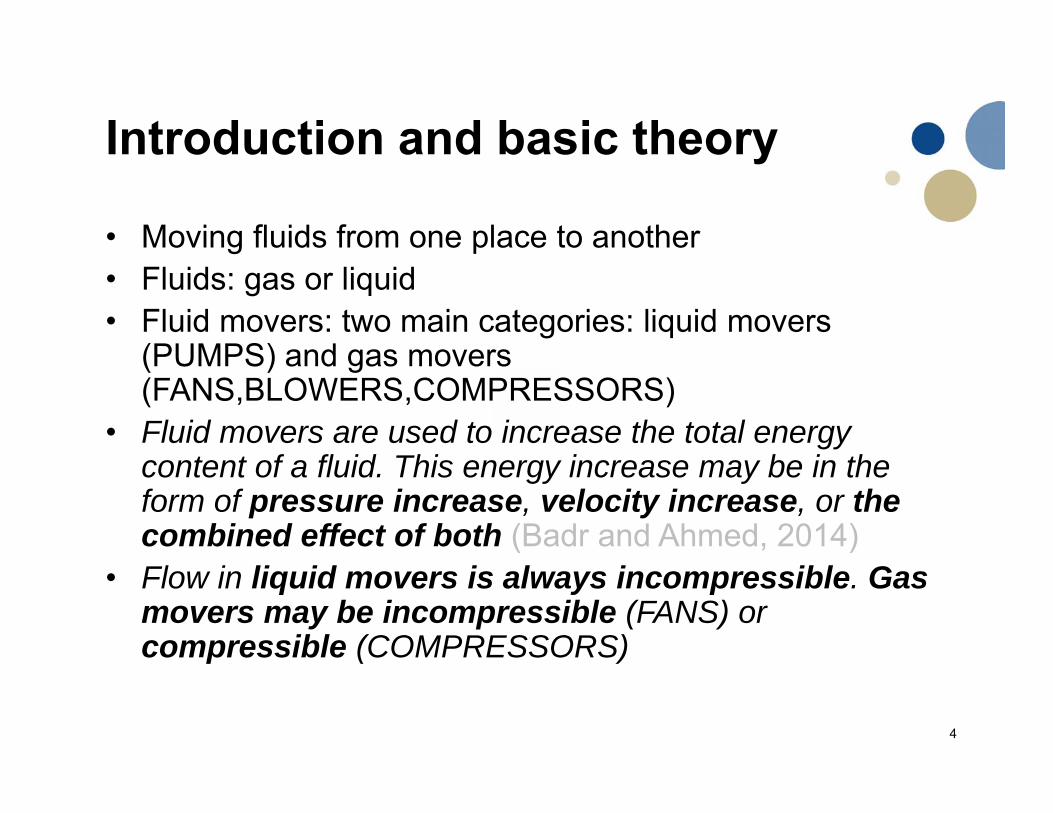
• Moving fluids from one place to another• Fluids: gas or liquid• Fluid movers: two main categories: liquid movers
(PUMPS) and gas movers (FANS,BLOWERS,COMPRESSORS)
• Fluid movers are used to increase the total energy content of a fluid. This energy increase may be in the form of pressure increase, velocity increase, or the combined effect of both (Badr and Ahmed, 2014)
• Flow in liquid movers is always incompressible. Gas movers may be incompressible (FANS) or compressible (COMPRESSORS)
5
Introduction and basic theory
Fluid Movers
Liquid Movers
Pumps
Gas Movers
FANS Blowers Compressors
Always Incompressible
fluid
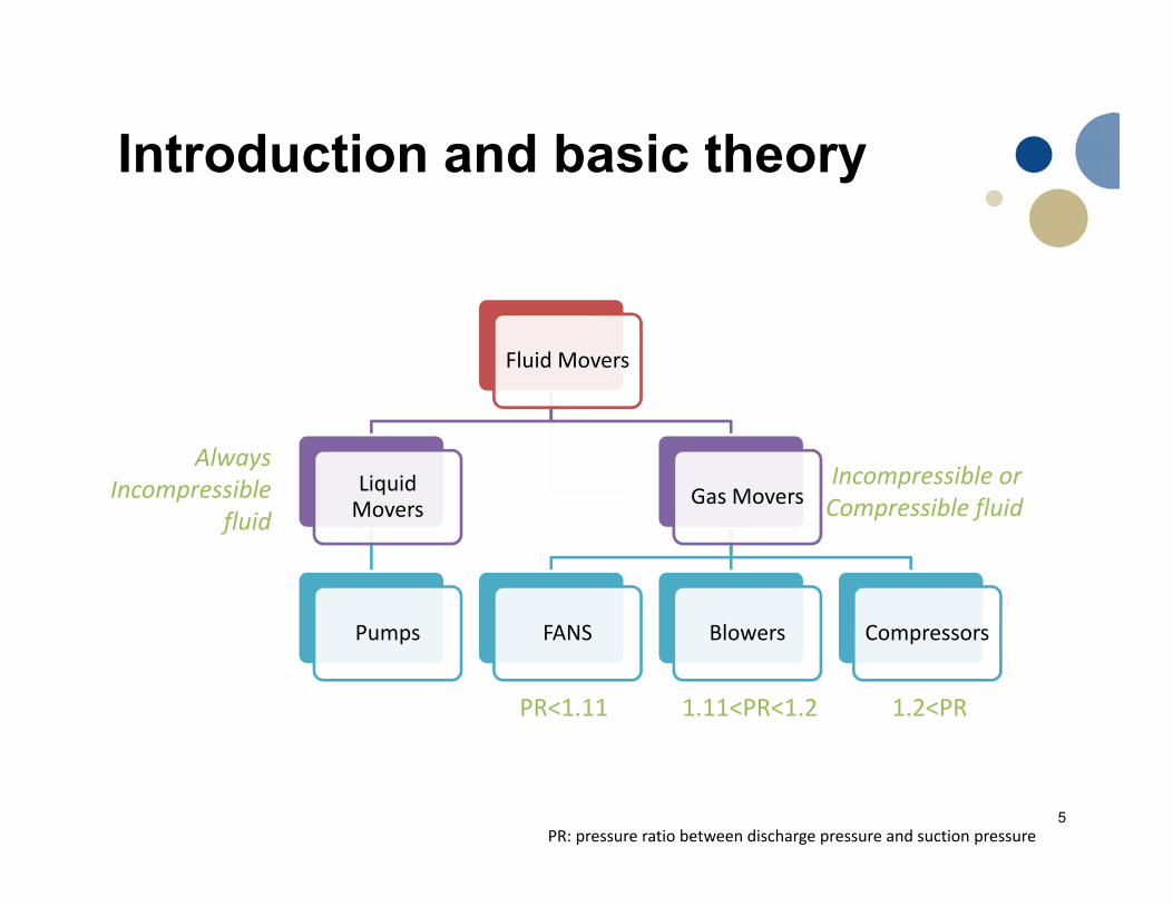
PR<1.11 1.11<PR<1.2 1.2<PR
Incompressible or Compressible fluid
PR: pressure ratio between discharge pressure and suction pressure

6
Introduction and basic theory
Fluid Movers
Liquid Movers
Pumps
Gas Movers
FANS Blowers Compressors
PR<1.11 1.11<PR<1.2 1.2<PR
Incompressible or Compressible fluid
PR: pressure ratio between discharge pressure and suction pressure
Always Incompressible
fluid

7
Introduction and basic theory
(Badr and Ahmed, 2014)
Performance characteristics depend on: • Fluid properties• Shape and size of the machine• Speed of rotation
A pump is a liquid mover that utilizes mechanical work to increase the total energy content of a fluid
8
Pumps
Dynamic PumpsSpecial‐effects
Positive Displacement Pumps
Radial (Centrifugal)
Rotodynamic Axial
Mixed‐flow
Piston
Reciprocating Plunger
Diaphragm
Rotary
Screw Single Rotor
Sliding vane
Gear
Multiple Rotor Lobe
Screw
9
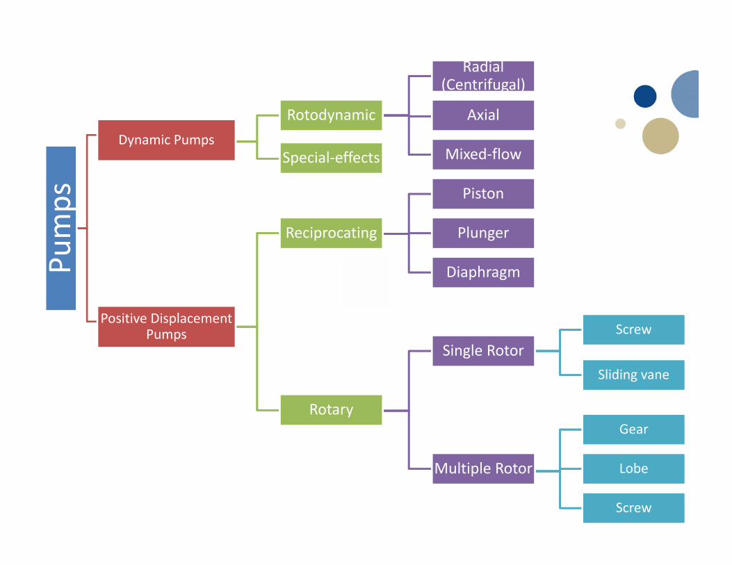
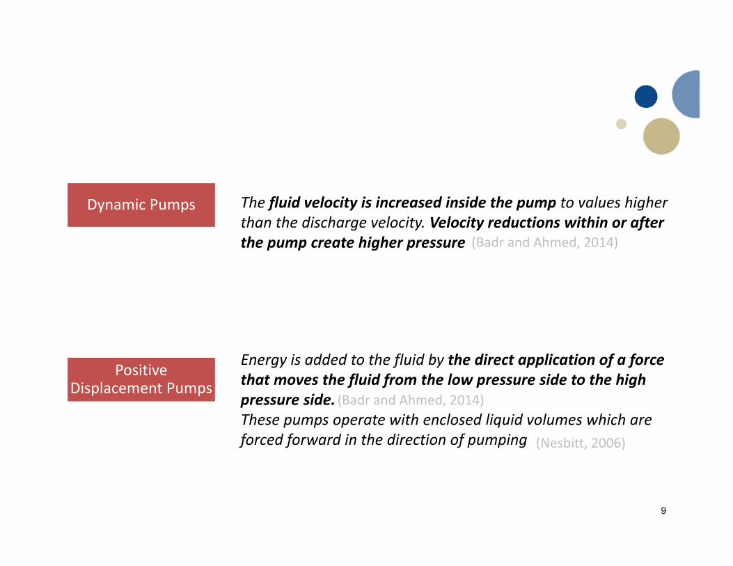
Energy is added to the fluid by the direct application of a force that moves the fluid from the low pressure side to the high pressure side. These pumps operate with enclosed liquid volumes which are forced forward in the direction of pumping
Dynamic Pumps The fluid velocity is increased inside the pump to values higher than the discharge velocity. Velocity reductions within or after the pump create higher pressure
(Badr and Ahmed, 2014)
Positive Displacement Pumps
(Nesbitt, 2006)
(Badr and Ahmed, 2014)

Radial (Centrifugal)
Rotodynamic Axial
Mixed‐flow
It is characterized by one or more impellers equipped with vanes which rotate in a pump casing
Dynamic Pumps

Rotodynamic
https://mechanicallyinfo.com/centrifugal‐pump‐working‐principle/
https://chemicalada.blogspot.com/2016/09/centrifugal‐pump.html
Radial (Centrifugal)
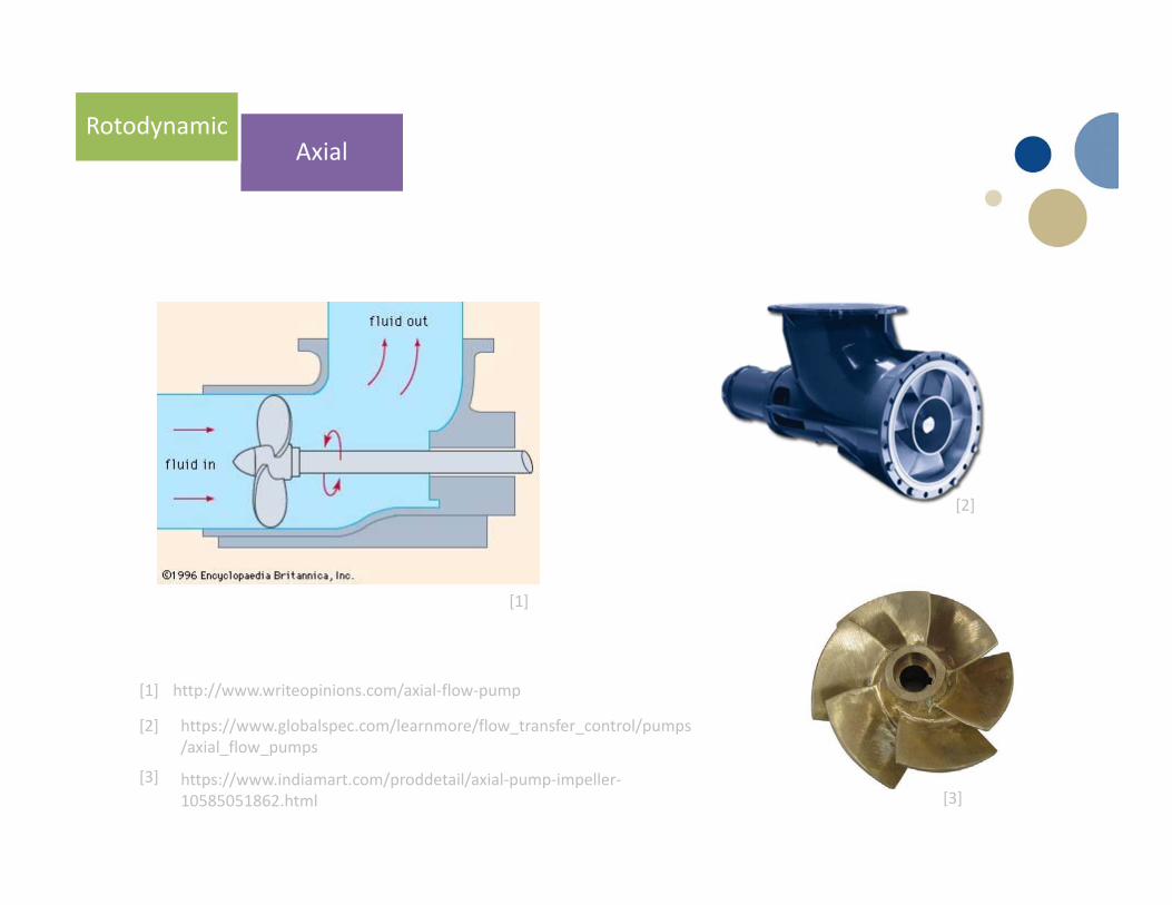
AxialRotodynamic
http://www.writeopinions.com/axial‐flow‐pump
https://www.globalspec.com/learnmore/flow_transfer_control/pumps/axial_flow_pumps
[1]
[2]
[1]
[2]
[3][3]
https://www.indiamart.com/proddetail/axial‐pump‐impeller‐10585051862.html

[1]
https://www.globalspec.com/learnmore/flow_control_flow_transfer/pumps/impellers[1]
[2]
[2] https://www.ksb.com/centrifugal‐pump‐lexicon/specific‐speed/191172/

Dynamic Pumps
Special‐effects
(Badr and Ahmed, 2014)
Jet Pump

Positive Displacement Pumps
Reciprocating
Rotary
http://marinersgalaxy.com/what‐is‐reciprocating‐pump‐and‐how‐i/[1]
[1]
https://www.brighthubengineering.com/marine‐engines‐machinery/41121‐working‐principle‐of‐rotary‐pumps/
[2]
[2]
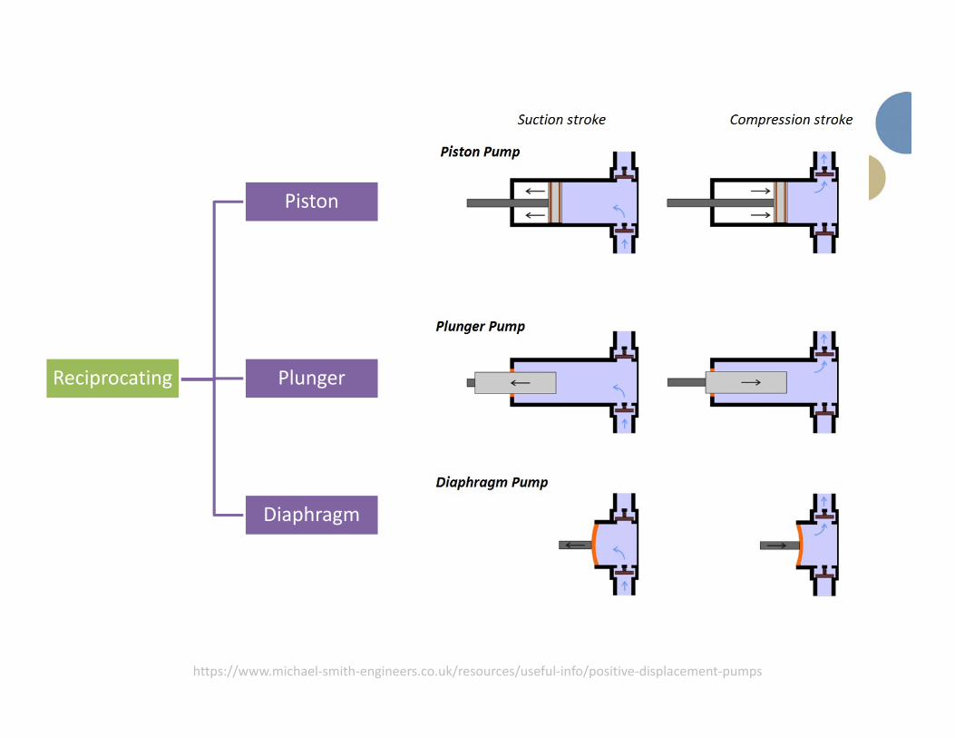
https://www.michael‐smith‐engineers.co.uk/resources/useful‐info/positive‐displacement‐pumps
Piston
Reciprocating Plunger
Diaphragm

Screw
Single Rotor
Rotary
https://www.michael‐smith‐engineers.co.uk/resources/useful‐info/positive‐displacement‐pumpshttps://www.dynapumps.com.au/pressure‐pumps/screw‐pumps.aspx
[1][2]
[2]

Screw
Single Rotor
Sliding vane
Rotary
https://www.michael‐smith‐engineers.co.uk/resources/useful‐info/positive‐displacement‐pumpshttps://www.dynapumps.com.au/pressure‐pumps/screw‐pumps.aspx
[1][2]
[1]
[2]
https://www.michael‐smith‐engineers.co.uk/resources/useful‐info/positive‐displacement‐pumps
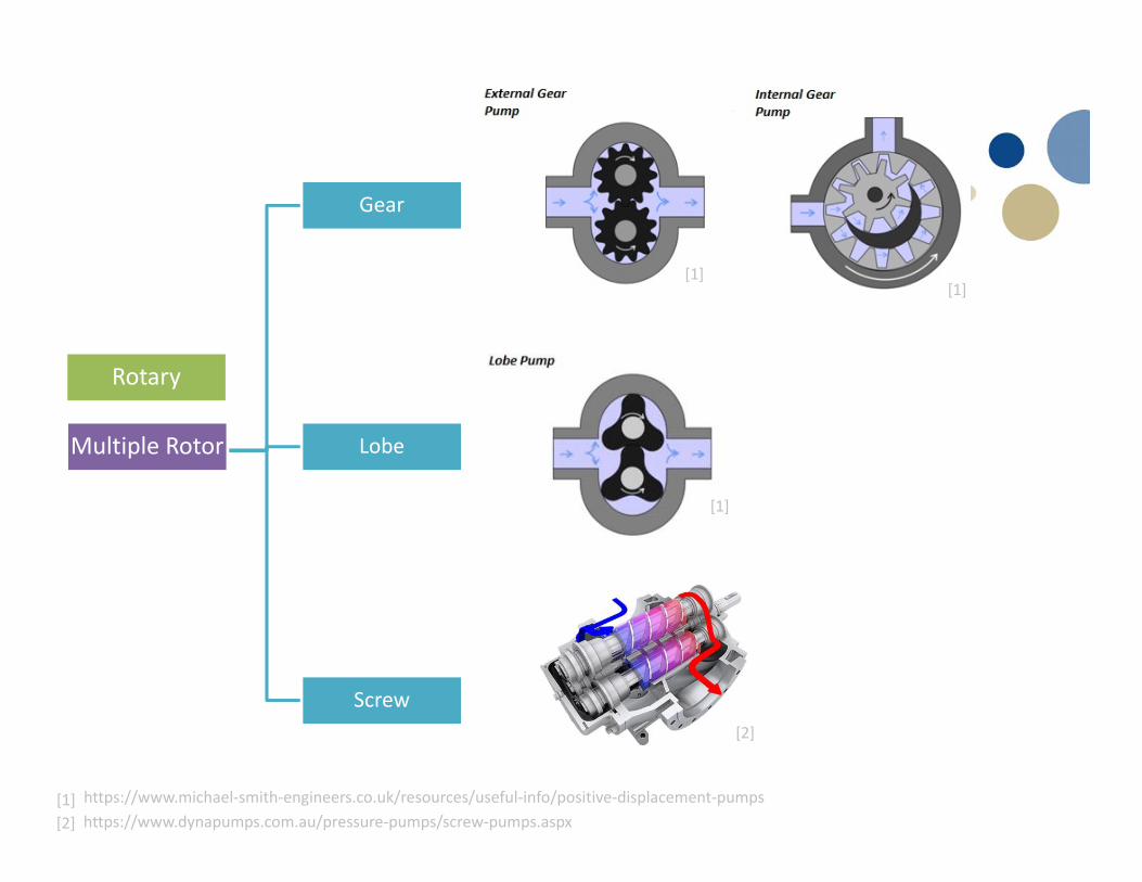
Rotary
Gear
Multiple Rotor Lobe
Screw
https://www.dynapumps.com.au/pressure‐pumps/screw‐pumps.aspx[1][2]
[1]
[1][1]
[2]
[1]

20
Sub-classifications
• Shape of casing: volute, double volute, diffuser, annular, tubular, split casing, etc
21
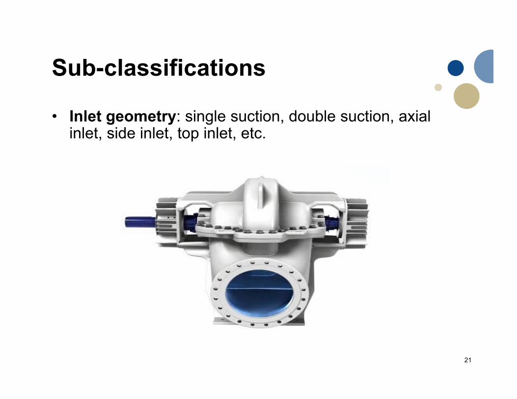
Sub-classifications
• Inlet geometry: single suction, double suction, axial inlet, side inlet, top inlet, etc.

22
Sub-classifications
• Layout: horizontal shaft, vertical shaft, or inclined shaft

23
Sub-classifications
• Number of stages: for radial and mixed flow centrifugal pumps they can be classified as single-stage, double stage, or multiple stage
24
Sub-classifications
• Liquid handled ( corrosive, abrasive, solid particles…)• Material of pump parts: material used for
manufacturing the impeller and pump casing• Type of prime mover: electric motors, diesel engines,
steam or gas turbines• Discharge pressure: low pressure, high pressure, or
high energy• Operating conditions: submersibles pumps, wet motor
pump, standby, and auxiliary pump:

25
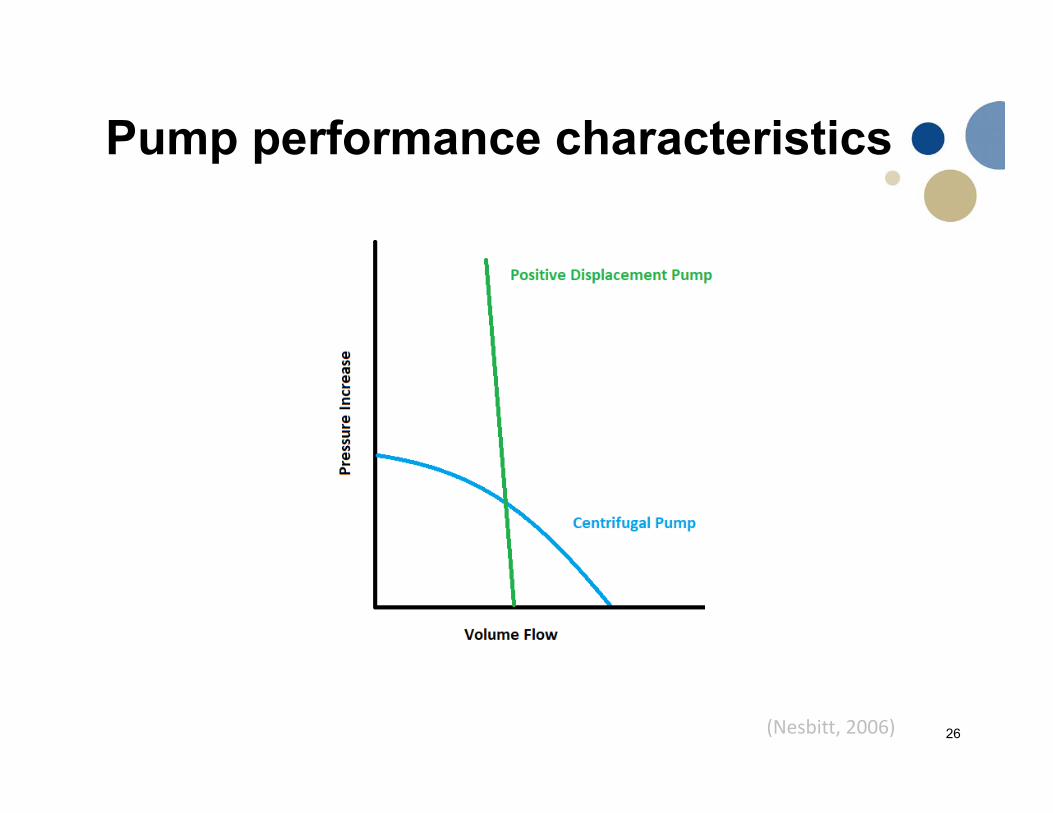
Determination of Flow Rate in a Pumping System• The flow in a pump is determined by the relationship of
the specified pump pressure increase to the back-pressure (the resistance in the system)
• The pipe system has a characteristic curve• The pump can only operate where the pump
characteristic intersects the system characteristic • The pump characteristics can be modified by adjusting
the pump speed• The system characteristics can be changed by opening
or closing valves or changing levels in tanks
(Nesbitt, 2006)
26
Pump performance characteristics
(Nesbitt, 2006)

27
System characteristic
(Badr and Ahmed, 2014)
Pump
System
http://www.hkdivedi.com/2015/05/difference‐between‐positive‐and‐non.html
Rotodynamic Pumps

30
Definitions and Terminology
1. Pump Capacity (Q)/ displacement: express the actual volume flow rate delivered by the pump
2. Pump Heads: – Static suction head ( ) pressure head at the suction nozzle at
zero flow rate– Static delivery head ( ) pressure head at the delivery nozzle
at zero flow rate– Total static head ( ) difference between the and
(Badr and Ahmed, 2014)

31
Definitions and Terminology
2. Pump Heads: – Pump suction head ( ): pressure head at the pump suction
nozzle when the pump is in operating condition
(Badr and Ahmed, 2014)
2
… friction head losses between the suction reservoir and the suction nozzle

32
Definitions and Terminology
2. Pump Heads: – Pump suction head ( ): pressure head at the pump suction
nozzle when the pump is in operating condition– Pump delivery head ( ): pressure head at the pump delivery
nozzle when the pump is in operating condition
(Badr and Ahmed, 2014)
2… friction head losses between the delivery nozzle and the receiving tank
33
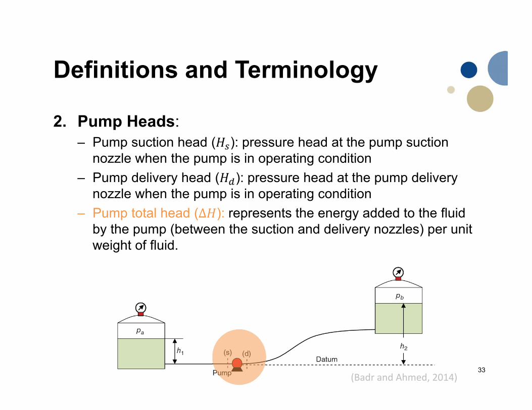
Definitions and Terminology
2. Pump Heads: – Pump suction head ( ): pressure head at the pump suction
nozzle when the pump is in operating condition– Pump delivery head ( ): pressure head at the pump delivery
nozzle when the pump is in operating condition– Pump total head (∆ ): represents the energy added to the fluid
by the pump (between the suction and delivery nozzles) per unit weight of fluid.
(Badr and Ahmed, 2014)

34
Definitions and Terminology
2. Pump Heads:
∆ 2
37
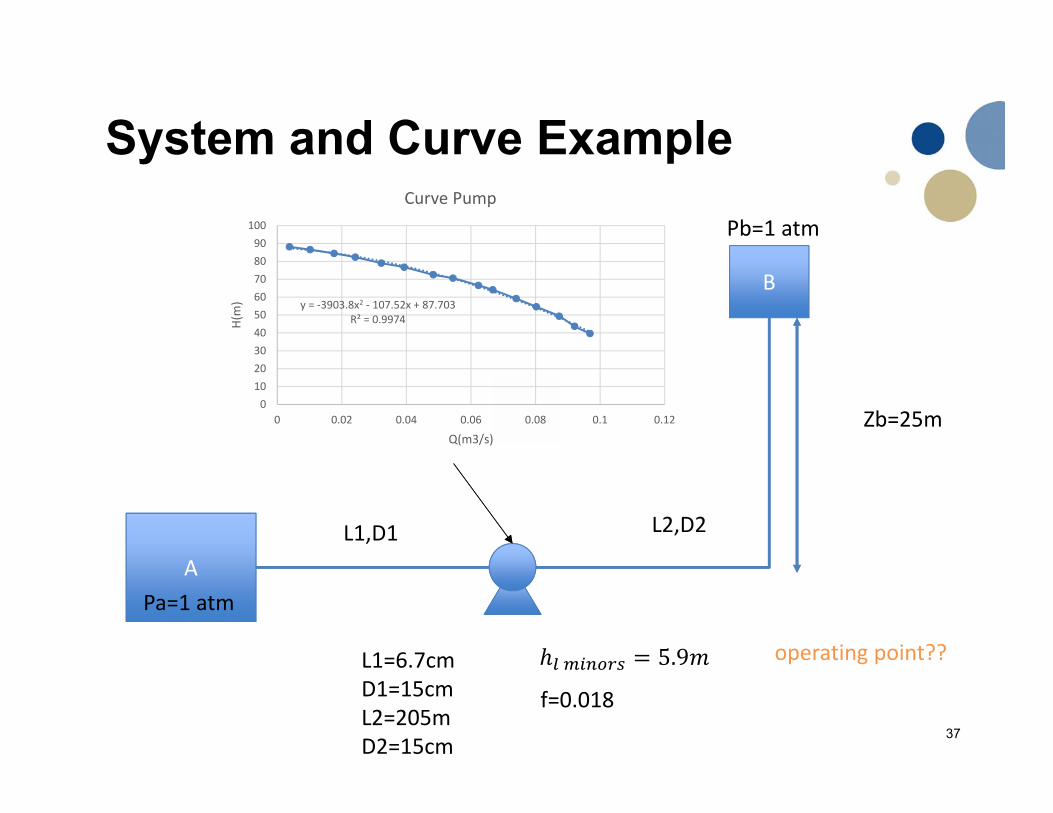
System and Curve Example
A
B
L1,D1 L2,D2
Pb=1 atm
Pa=1 atm
y = ‐3903.8x2 ‐ 107.52x + 87.703R² = 0.9974
0102030405060708090
100
0 0.02 0.04 0.06 0.08 0.1 0.12
H(m)
Q(m3/s)
Curve Pump
L1=6.7cmD1=15cmL2=205mD2=15cm
5.9
f=0.018
operating point??
Zb=25m

38
System and Curve Example
System characteristic ∆
Suction line From A to Pump suction 2 ∆
Discharge line From Pump discharge to B2 ∆
∆ 2 ∆
∆ = ∑∆

39
Head losses
System and Curve Example
∆ ∆ ∆ 2 2 2 5.9
f=0.018
=
∆ 5093
∆ = ∑∆ 25 5093System Curve
40
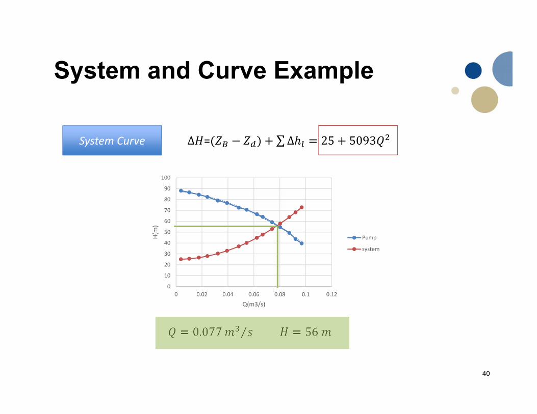
System and Curve Example
∆ = ∑∆ 25 5093System Curve
0
10
20
30
40
50
60
70
80
90
100
0 0.02 0.04 0.06 0.08 0.1 0.12
H(m)
Q(m3/s)
Pump
system
0.077 ⁄ 56

41
Definitions and Terminology
3. Pump performance characteristics– It refers to the relationship between each of the total head (H),
the pump power consumption (BP), the pump overall efficiency ( )
(Badr and Ahmed, 2014)
Typical performance curve for a radial‐type centrifugal pump operating at a constant speed

42
Definitions and Terminology
3. Pump performance characteristics– Presented as a set of Iso-efficiency curves at:
• Different speeds• Different size for geometrically similar pumps at constant speed
(Badr and Ahmed, 2014)
Different speeds
Typical for a radial‐type centrifugal pump
Different Impeller Diameter