TPac DBL SureFire Preaction
28
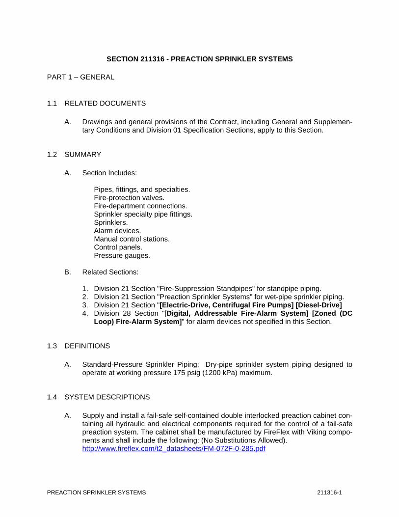
PREACTION SPRINKLER SYSTEMS 211316-1 SECTION 211316 - PREACTION SPRINKLER SYSTEMS PART 1 – GENERAL 1.1 RELATED DOCUMENTS A. Drawings and general provisions of the Contract, including General and Supplemen- tary Conditions and Division 01 Specification Sections, apply to this Section. 1.2 SUMMARY A. Section Includes: Pipes, fittings, and specialties. Fire-protection valves. Fire-department connections. Sprinkler specialty pipe fittings. Sprinklers. Alarm devices. Manual control stations. Control panels. Pressure gauges. B. Related Sections: 1. Division 21 Section "Fire-Suppression Standpipes" for standpipe piping. 2. Division 21 Section "Preaction Sprinkler Systems" for wet-pipe sprinkler piping. 3. Division 21 Section "[Electric-Drive, Centrifugal Fire Pumps] [Diesel-Drive] 4. Division 28 Section "[Digital, Addressable Fire-Alarm System] [Zoned (DC Loop) Fire-Alarm System]" for alarm devices not specified in this Section. 1.3 DEFINITIONS A. Standard-Pressure Sprinkler Piping: Dry-pipe sprinkler system piping designed to operate at working pressure 175 psig (1200 kPa) maximum. 1.4 SYSTEM DESCRIPTIONS A. Supply and install a fail-safe self-contained double interlocked preaction cabinet con- taining all hydraulic and electrical components required for the control of a fail-safe preaction system. The cabinet shall be manufactured by FireFlex with Viking compo- nents and shall include the following: (No Substitutions Allowed). http://www.fireflex.com/t2_datasheets/FM-072F-0-285.pdf
-
Upload
ionut-somnea -
Category
Documents
-
view
46 -
download
4
description
Preaction sprinklers
Transcript of TPac DBL SureFire Preaction
PREACTION SPRINKLER SYSTEMS 211316-1
SECTION 211316 - PREACTION SPRINKLER SYSTEMS
PART 1 – GENERAL
1.1 RELATED DOCUMENTS
A. Drawings and general provisions of the Contract, including General and Supplemen-tary Conditions and Division 01 Specification Sections, apply to this Section.
1.2 SUMMARY
A. Section Includes:
Pipes, fittings, and specialties. Fire-protection valves. Fire-department connections. Sprinkler specialty pipe fittings. Sprinklers. Alarm devices. Manual control stations. Control panels. Pressure gauges.
B. Related Sections:
1. Division 21 Section "Fire-Suppression Standpipes" for standpipe piping. 2. Division 21 Section "Preaction Sprinkler Systems" for wet-pipe sprinkler piping. 3. Division 21 Section "[Electric-Drive, Centrifugal Fire Pumps] [Diesel-Drive] 4. Division 28 Section "[Digital, Addressable Fire-Alarm System] [Zoned (DC
Loop) Fire-Alarm System]" for alarm devices not specified in this Section.
1.3 DEFINITIONS
A. Standard-Pressure Sprinkler Piping: Dry-pipe sprinkler system piping designed to operate at working pressure 175 psig (1200 kPa) maximum.
1.4 SYSTEM DESCRIPTIONS
A. Supply and install a fail-safe self-contained double interlocked preaction cabinet con-taining all hydraulic and electrical components required for the control of a fail-safe preaction system. The cabinet shall be manufactured by FireFlex with Viking compo-nents and shall include the following: (No Substitutions Allowed).
http://www.fireflex.com/t2_datasheets/FM-072F-0-285.pdf
PREACTION SPRINKLER SYSTEMS 211316-2
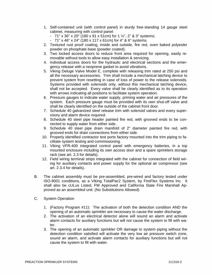
1. Self-contained unit (with control panel) in sturdy free-standing 14 gauge steel cabinet, measuring with control panel: - 71" x 36" x 20" (180 x 91 x 51cm) for 1 ½", 2" & 3" systems; - 71" x 46" x 24" (180 x 117 x 61cm) for 4" & 6" systems.
2. Textured rust proof coating, inside and outside, fire red, oven baked polyester powder on phosphate base (powder coated).
3. Two locked access doors to reduce front area required for opening, easily re-movable without tools to allow easy installation & servicing.
4. Individual access doors for the hydraulic and electrical sections and the emer-gency release with a neoprene gasket to avoid vibrations.
5. Viking Deluge Valve Model E, complete with releasing trim rated at 250 psi and all the necessary accessories. Trim shall include a mechanical latching device to prevent system from resetting in case of loss of power to the release solenoids. Systems provided with solenoids only, without this mechanical latching device, shall not be accepted. Every valve shall be clearly identified as to its operation with arrows indicating all positions to facilitate system operation.
6. Pressure gauges to indicate water supply, priming water and air pressures of the system. Each pressure gauge must be provided with its own shut-off valve and shall be clearly identified on the outside of the cabinet front door.
7. Schedule 40 galvanized steel release trim with solenoid valves and every super-visory and alarm device required.
8. Schedule 40 steel pipe header painted fire red, with grooved ends to be con-nected to supply water from either side.
9. Schedule 40 steel pipe drain manifold of 2" diameter painted fire red, with grooved ends for drain connections from either side.
10. Properly identified contractor test ports factory mounted into the trim piping to fa-cilitate system testing and commissioning.
11. Viking VFR-400 integrated control panel with emergency batteries, in a top mounted enclosure including its own access door and a spare sprinklers storage rack (see art. 2.3 for details).
12. Field wiring terminal strips integrated with the cabinet for connection of field wir-ing for auxiliary contacts and power supply for the optional air compressor (see art. 2.3.4 for details).
B. The cabinet assembly must be pre-assembled, pre-wired and factory tested under
ISO-9001 conditions, as a Viking TotalPac2 System, by FireFlex Systems Inc. It shall also be cULus Listed, FM Approved and California State Fire Marshall Ap-proved as an assembled unit. (No Substitutions Allowed)
C. System Operation
1. (Factory Program #11): The activation of both the detection condition AND the
opening of an automatic sprinkler are necessary to cause the water discharge. 2. The activation of an electrical detector alone will sound an alarm and activate
alarm contacts for auxiliary functions but will not cause the system to fill with wa-ter.
3. The opening of an automatic sprinkler OR damage to system piping without the detection condition satisfied will activate the very low air pressure switch zone, sound an alarm, and activate alarm contacts for auxiliary functions but will not cause the system to fill with water.
PREACTION SPRINKLER SYSTEMS 211316-3
4. Activation of BOTH the detection condition AND the opening of an automatic sprinkler will activate the solenoid valves, open the deluge valve, and cause wa-ter to discharge. This will sound an alarm and activate alarm and water flow con-tacts for auxiliary functions.
5. Operation of the emergency manual release will depressurize the priming cham-ber of the deluge valve, causing the system to fill the piping network with water, and activate alarm and water flow contacts for auxiliary functions.
6. If the AC Power fails and the battery backup power expires before an alarm is detected, the preaction system should “fail-safe” and function as a dry pipe sys-tem. The opening of an automatic sprinkler OR damage to system piping will cause the system to fill and flow water until it is manually shut-off.
1.5 PERFORMANCE REQUIREMENTS
A. Supply to release control panel
1. Supply and install one dedicated 110VAC, 60Hz branch circuit to power each of the release control panel.
2. Supply and install a second branch circuit, 110VAC, 60Hz for each of the air compressor provided inside the preaction cabinet by the factory.
3. The (two) independent circuit(s) for each preaction systems shall be well identi-fied and their circuit breaker locked.
B. Standard-Pressure Piping System Component: Listed for 175-psig (1200-kPa) mini-
mum working pressure. C. Delegated Design: Design sprinkler system(s), including comprehensive engineering
analysis by a qualified professional engineer, using performance requirements and design criteria indicated.
1. Available fire-hydrant flow test records indicate the following conditions:
a. Date: <Insert test date>. b. Time: <Insert time> [a.m.] [p.m.] c. Performed by: <Insert operator's name> of <Insert firm>. d. Location of Residual Fire Hydrant R: <Insert location>. e. Location of Flow Fire Hydrant F: <Insert location>. f. Static Pressure at Residual Fire Hydrant R: <Insert psig (kPa)>. g. Measured Flow at Flow Fire Hydrant F: <Insert gpm (L/s)>. h. Residual Pressure at Residual Fire Hydrant R: <Insert psig (kPa)>.
D. Sprinkler system design shall be approved by authorities having jurisdiction.
1. Margin of Safety for Available Water Flow and Pressure: <Insert number> per-cent, including losses through water-service piping, valves, and backflow pre-venters.
2. Sprinkler Occupancy Hazard Classifications:
a. Mechanical Equipment Rooms: <Insert classification>. b. Office and Public Areas: <Insert classification>.
PREACTION SPRINKLER SYSTEMS 211316-4
3. Minimum Density for Automatic-Sprinkler Piping Design:
a. Light-Hazard Occupancy: <Insert value> area. b. Ordinary-Hazard, Group 1 Occupancy: <Insert value> area. c. Ordinary-Hazard, Group 2 Occupancy: <Insert value> area. d. Extra-Hazard, Group 1 Occupancy: <Insert value> area. e. Extra-Hazard, Group 2 Occupancy: <Insert value> area. f. Special Occupancy Hazard: As determined by authorities having jurisdiction.
4. Maximum Protection Area per Sprinkler: Per UL listing.
5. Maximum Protection Area per Sprinkler:
a. Office Spaces: <Insert dimension>. b. Storage Areas: <Insert dimension>. c. Mechanical Equipment Rooms: <Insert dimension>. d. Electrical Equipment Rooms: <Insert dimension>. e. Other Areas: According to NFPA 13 recommendations unless otherwise indi-
cated.
6. Total Combined Hose-Stream Demand Requirement: According to NFPA 13 unless otherwise indicated:
a. Light-Hazard Occupancies: <Insert requirement>. b. Ordinary-Hazard Occupancies: <Insert requirement>. c. Extra-Hazard Occupancies: <Insert requirement>. d. <Insert requirement>.
E. Seismic Performance: Sprinkler piping shall withstand the effects of earthquake mo-
tions determined according to NFPA 13 and <Insert requirement>.
1.6 ACTION SUBMITTALS
A. Product Data: For each type of product indicated. [Include rated capacities, oper-ating characteristics, electrical characteristics, and furnished specialties and accessories.]
B. Shop Drawings: For preaction sprinkler systems. Include plans, elevations, sec-
tions, details, and attachments to other work.
1. Wiring Diagrams: For power, signal, and control wiring.
C. Delegated-Design Submittal: For sprinkler systems indicated to comply with per-formance requirements and design criteria, including analysis data signed and sealed by the qualified professional engineer responsible for their preparation.
PREACTION SPRINKLER SYSTEMS 211316-5
1.7 INFORMATIONAL SUBMITTALS
A. Coordination Drawings: Sprinkler systems, drawn to scale, on which the following items are shown and coordinated with each other, using input from installers of the items involved:
1. Domestic water piping. 2. Compressed air piping. 3. Items penetrating finished ceiling including the following:
a. Lighting fixtures. b. Air outlets and inlets. c. <Insert item>.
4. <Insert item>.
B. Qualification Data: For qualified Installer [and professional engineer]. C. Approved Sprinkler Piping Drawings: Working plans, prepared according to
NFPA 13, which have been approved by authorities having jurisdiction, including hy-draulic calculations if applicable.
D. Fire-hydrant flow test report. E. Field Test Reports and Certificates: Indicate and interpret test results for compliance
with performance requirements and as described in NFPA 13. Include "Contractor's Material and Test Certificate for Aboveground Piping."
F. Field quality-control reports.
1.8 CLOSEOUT SUBMITTALS
A. Operation and Maintenance Data: For sprinkler specialties to include in emergency, operation, and maintenance manuals.
http://www.fireflex.com/t2_manuals/surefire.pdf
1.9 MAINTENANCE MATERIAL SUBMITTALS
A. Furnish extra materials that match products installed and that are packaged with pro-tective covering for storage and identified with labels describing contents.
1. Sprinkler Cabinets: Finished, wall-mounted, steel cabinet with hinged cover, and
with space for minimum of six spare sprinklers plus sprinkler wrench. Include number of sprinklers required by NFPA 13 and sprinkler wrench. Include sepa-rate cabinet with sprinklers and wrench for each type of sprinkler used on Pro-ject.
PREACTION SPRINKLER SYSTEMS 211316-6
1.10 QUALITY ASSURANCE
A. Installer Qualifications:
1. Installer's responsibilities include designing, fabricating, and installing sprinkler systems and providing professional engineering services needed to assume en-gineering responsibility. Base calculations on results of fire-hydrant flow test.
a. Engineering Responsibility: Preparation of working plans, calculations, and
field test reports by a qualified professional engineer.
B. Electrical Components, Devices, and Accessories: Listed and labeled as defined in NFPA 70, by a qualified testing agency, and marked for intended location and appli-cation.
C. NFPA Standards: Sprinkler system equipment, specialties, accessories, installation,
and testing shall comply with the following:
1. NFPA 13, "Installation of Sprinkler Systems." 2. NFPA 13R, "Installation of Sprinkler Systems in Residential Occupancies up to
and Including Four Stories in Height." 3. NFPA 24, "Installation of Private Fire Service Mains and Their Appurtenances."
1.11 PROJECT CONDITIONS
A. Interruption of Existing Sprinkler Service: Do not interrupt sprinkler service to facili-ties occupied by Owner or others unless permitted under the following conditions and then only after arranging to provide temporary sprinkler service according to re-quirements indicated:
1. Notify [Architect] [Construction Manager] [Owner] no fewer than <Insert num-
ber> days in advance of proposed interruption of sprinkler service. 2. Do not proceed with interruption of sprinkler service without [Architect's] [Con-
struction Manager's] [Owner's] written permission.
1.12 COORDINATION
A. Coordinate layout and installation of sprinklers with other construction that pene-trates ceilings, including light fixtures, HVAC equipment, and partition assemblies.
PART 2 - PRODUCTS
PREACTION SPRINKLER SYSTEMS 211316-7
2.1 PIPING MATERIALS
A. Comply with requirements in "Piping Schedule" Article for applications of pipe, tube, and fitting materials, and joining methods for specific services, service locations, and pipe sizes.
2.2 STEEL PIPE AND FITTINGS
A. Standard Weight, Galvanized-Steel Pipe: ASTM A 53/A 53M, <Insert type>, <In-sert grade>. Pipe ends may be factory or field formed to match joining method.
B. Schedule 30, Galvanized-Steel Pipe: ASTM A 135; ASTM A 795/A 795M, <Insert
type>; or ASME B36.10M, wrought steel; with wall thickness not less than Sched-ule 30 and not more than Schedule 40. Pipe ends may be factory or field formed to match joining method.
C. Thinwall Galvanized-Steel Pipe: ASTM A 135 or ASTM A 795/A 795M, threadable,
with wall thickness less than Schedule 30 and equal to or greater than Schedule 10. Pipe ends may be factory or field formed to match joining method.
D. Galvanized-Steel Pipe Nipples: ASTM A 733, made of ASTM A 53/A 53M, standard-
weight, seamless steel pipe with threaded ends. E. Galvanized, Steel Couplings: ASTM A 865, threaded. F. Galvanized, Gray-Iron Threaded Fittings: ASME B16.4, Class 125, standard pattern.
G. Malleable- or Ductile-Iron Unions: UL 860. H. Cast-Iron Flanges: ASME B16.1, Class 125.
Grooved-Joint, Steel-Pipe Appurtenances:
1. Manufacturers: Subject to compliance with requirements, [provide products by
one of the following] [available manufacturers offering products that may be incorporated into the Work include, but are not limited to, the following]:
a. Anvil International, Inc. b. Ward c. Star Corporation d. <Insert manufacturer's name>
2. Pressure Rating: [175 psig (1200 kPa)] [250 psig (1725 kPa)] [300 psig (2070
kPa)] minimum. 3. Galvanized, Grooved-End Fittings for Steel Piping: ASTM A 47/A 47M, malle-
able-iron casting or ASTM A 536, ductile-iron casting; with dimensions matching steel pipe.
PREACTION SPRINKLER SYSTEMS 211316-8
4. Grooved-End-Pipe Couplings for Steel Piping: AWWA C606 and UL 213, rigid pattern, unless otherwise indicated, for steel-pipe dimensions. Include ferrous housing sections, EPDM-rubber gasket, and bolts and nuts.
2.3 PIPING JOINING MATERIALS
A. Pipe-Flange Gasket Materials: [AWWA C110, rubber, flat face, 1/8 inch (3.2 mm) thick] [or] [ASME B16.21, nonmetallic and asbestos free].
1. Class 125, Cast-Iron and Class 150, Bronze Flat-Face Flanges: Full-face gas-
kets. 2. Class 250, Cast-Iron and Class 300, Raised-Face Flanges: Ring-type gaskets.
B. Metal, Pipe-Flange Bolts and Nuts: ASME B18.2.1, carbon steel unless otherwise
indicated. C. Brazing Filler Metals: AWS A5.8/A5.8M, BCuP Series, copper-phosphorus alloys for
general-duty brazing unless otherwise indicated.
2.4 LISTED FIRE-PROTECTION VALVES
A. General Requirements:
1. Valves shall be UL listed or FM approved. 2. Minimum Pressure Rating for Standard-Pressure Piping: 175 psig (1200 kPa).
B. Ball Valves:
1. Manufacturers: Subject to compliance with requirements, [provide products by
one of the following] [available manufacturers offering products that may be incorporated into the Work include, but are not limited to, the following]:
2. Basis-of-Design Product: Subject to compliance with requirements, provide <In-sert manufacturer's name; product name or designation> or comparable product by one of the following:
a. Anvil International, Inc. b. Viking Company. c. <Insert manufacturer's name>
3. Standard: UL 1091 except with ball instead of disc. 4. Valves NPS 1-1/2 (DN 40) and Smaller: Bronze body with threaded ends. 5. Valves NPS 2 and NPS 2-1/2 (DN 50 and DN 65): Bronze body with threaded
ends or ductile-iron body with grooved ends. 6. Valves NPS 3 (DN 80): Ductile-iron body with grooved ends.
C. Bronze Butterfly Valves:

PREACTION SPRINKLER SYSTEMS 211316-9
1. Manufacturers: Subject to compliance with requirements, [provide products by one of the following] [available manufacturers offering products that may be incorporated into the Work include, but are not limited to, the following]:
2. Basis-of-Design Product: Subject to compliance with requirements, provide <In-sert manufacturer's name; product name or designation> or comparable product by one of the following:
a. Nibco b. Global Safety Products, Inc. c. Milwaukee Valve Company. d. <Insert manufacturer's name>.
3. Standard: UL 1091. 4. Pressure Rating: 175 psig (1200 kPa). 5. Body Material: Bronze. 6. End Connections: Threaded.
D. Iron Butterfly Valves:
1. Manufacturers: Subject to compliance with requirements, [provide products by one of the following] [available manufacturers offering products that may be incorporated into the Work include, but are not limited to, the following]:
2. Basis-of-Design Product: Subject to compliance with requirements, provide <In-sert manufacturer's name; product name or designation> or comparable product by one of the following:
a. Anvil International, Inc. b. Kennedy Valve; a division of McWane, Inc. c. Milwaukee Valve Company. d. NIBCO INC. e. Viking f. FireFlex g. <Insert manufacturer's name>
3. Standard: UL 1091. 4. Pressure Rating: 175 psig (1200 kPa). 5. Body Material: Cast or ductile iron. 6. Style: Lug or wafer. 7. End Connections: Grooved.
E. Check Valves:
1. Manufacturers: Subject to compliance with requirements, [provide products by
one of the following] [available manufacturers offering products that may be incorporated into the Work include, but are not limited to, the following]:
2. Basis-of-Design Product: Subject to compliance with requirements, provide <In-sert manufacturer's name; product name or designation> or comparable product by one of the following:
a. Kennedy Valve; a division of McWane, Inc.
PREACTION SPRINKLER SYSTEMS 211316-10
b. NIBCO INC. c. Potter Roemer. d. Viking Corporation. e. Watts Water Technologies, Inc. f. Ames g. <Insert manufacturer's name>
3. Standard: UL 312 4. Pressure Rating: [250 psig (1725 kPa) minimum] [300 psig (2070 kPa)]. 5. Type: Swing check. 6. Body Material: Cast iron. 7. End Connections: Flanged or grooved.
F. Bronze OS&Y Gate Valves:
1. Manufacturers: Subject to compliance with requirements, [provide products by
one of the following] [available manufacturers offering products that may be incorporated into the Work include, but are not limited to, the following]:
2. Basis-of-Design Product: Subject to compliance with requirements, provide <In-sert manufacturer's name; product name or designation> or comparable product by one of the following:
a. NIBCO INC. b. United Brass Works, Inc. c. <Insert manufacturer's name>
3. Standard: UL 262. 4. Pressure Rating: 175 psig (1200 kPa). 5. Body Material: Bronze. 6. End Connections: Threaded.
G. Iron OS&Y Gate Valves:
1. Manufacturers: Subject to compliance with requirements, [provide products by
one of the following] [available manufacturers offering products that may be incorporated into the Work include, but are not limited to, the following]:
2. Basis-of-Design Product: Subject to compliance with requirements, provide <In-sert manufacturer's name; product name or designation> or comparable product by one of the following:
a. NIBCO INC. b. United Brass Works, Inc. c. Watts Water Technologies, Inc. d. Ames e. Kennedy Valve; a division of McWane, Inc. f. <Insert manufacturer's name>
3. Standard: UL 262. 4. Pressure Rating: [250 psig (1725 kPa) minimum] [300 psig (2070 kPa)]. 5. Body Material: Cast or ductile iron. 6. End Connections: Flanged or grooved.
PREACTION SPRINKLER SYSTEMS 211316-11
H. Indicating-Type Butterfly Valves:
1. Manufacturers: Subject to compliance with requirements, [provide products by
one of the following] [available manufacturers offering products that may be incorporated into the Work include, but are not limited to, the following]:
2. Basis-of-Design Product: Subject to compliance with requirements, provide <In-sert manufacturer's name; product name or designation> or comparable product by one of the following:
a. Kennedy Valve; a division of McWane, Inc. b. NIBCO INC. c. Viking d. <Insert manufacturer's name>
3. Standard: UL 1091. 4. Pressure Rating: 175 psig (1200 kPa) minimum. 5. Valves NPS 2 (DN 50) and Smaller:
a. Valve Type: Ball or butterfly. b. Body Material: Bronze. c. End Connections: Threaded.
6. Valves NPS 2-1/2 (DN 65) and Larger:
a. Valve Type: Butterfly. b. Body Material: Cast or ductile iron. c. End Connections: Flanged, grooved, or wafer.
7. Valve Operation: Integral [electrical, 115-V ac, prewired, single-circuit, su-
pervisory switch] [electrical, 115-V ac, prewired, two-circuit, supervisory switch] [visual] indicating device.
I. NRS Gate Valves:
1. Manufacturers: Subject to compliance with requirements, [provide products by
one of the following] [available manufacturers offering products that may be incorporated into the Work include, but are not limited to, the following]:
2. Basis-of-Design Product: Subject to compliance with requirements, provide <In-sert manufacturer's name; product name or designation> or comparable product by one of the following:
a. Kennedy Valve; a division of McWane, Inc. b. Mueller Co.; Water Products Division. c. NIBCO INC. d. <Insert manufacturer's name>
3. Standard: UL 262. 4. Pressure Rating: [250 psig (1725 kPa) minimum] [300 psig (2070 kPa)]. 5. Body Material: Cast iron with indicator post flange. 6. Stem: Nonrising.
PREACTION SPRINKLER SYSTEMS 211316-12
7. End Connections: Flanged or grooved.
J. Indicator Posts:
1. Manufacturers: Subject to compliance with requirements, [provide products by one of the following] [available manufacturers offering products that may be incorporated into the Work include, but are not limited to, the following]:
2. Basis-of-Design Product: Subject to compliance with requirements, provide <In-sert manufacturer's name; product name or designation> or comparable product by one of the following:
a. Kennedy Valve; a division of McWane, Inc. b. Mueller Co.; Water Products Division. c. NIBCO INC. d. <Insert manufacturer's name>
3. Standard: UL 789. 4. Type: Horizontal for wall mounting. 5. Body Material: Cast iron with extension rod and locking device. 6. Operation: [Wrench] [Hand wheel].
2.5 TRIM AND DRAIN VALVES
A. General Requirements:
1. Standard: UL's "Fire Protection Equipment Directory" listing or "Approval Guide," published by FM Global, listing.
2. Pressure Rating: 175 psig (1200 kPa) minimum.
B. Angle Valves:
1. Manufacturers: Subject to compliance with requirements, [provide products by one of the following] [available manufacturers offering products that may be incorporated into the Work include, but are not limited to, the following]:
a. Fire Protection Products, Inc. b. United Brass Works, Inc. c. Nibco d. <Insert manufacturer's name>
C. Ball Valves:
1. Manufacturers: Subject to compliance with requirements, [provide products by one of the following] [available manufacturers offering products that may be incorporated into the Work include, but are not limited to, the following]:
a. Kennedy Valve; a division of McWane, Inc. b. Milwaukee Valve Company. c. NIBCO INC. d. Potter Roemer.
PREACTION SPRINKLER SYSTEMS 211316-13
e. United Brass f. Watts Water Technologies, Inc. g. <Insert manufacturer's name>
D. Globe Valves:
1. Manufacturers: Subject to compliance with requirements, [provide products by
one of the following] [available manufacturers offering products that may be incorporated into the Work include, but are not limited to, the following]:
a. Fire Protection Products, Inc. b. United Brass Works, Inc. c. Nibco d. <Insert manufacturer's name>
E. Plug Valves:
1. Manufacturers: Subject to compliance with requirements, [provide products by
one of the following] [available manufacturers offering products that may be incorporated into the Work include, but are not limited to, the following]:
a. Southern Manufacturing Group. b. <Insert manufacturer's name>
2.6 SPECIALTY VALVES
A. General Requirements:
1. Standard: UL's "Fire Protection Equipment Directory" listing or "Approval Guide," published by FM Global, listing.
2. Pressure Rating:
a. Standard-Pressure Piping Specialty Valves: 175 psig (1200 kPa) minimum. b. High-Pressure Piping Specialty Valves: [250 psig (1725 kPa) minimum]
[300 psig (2070 kPa)].
3. Body Material: Cast or ductile iron. 4. Size: Same as connected piping. 5. End Connections: Flanged or grooved.
B. Deluge Valves:
Viking Deluge Valve Model E or Model F, complete with releasing trim rated at 250 psi and all the necessary accessories. Trim shall include a mechanical latching de-vice to prevent system from resetting in case of loss of power to the release sole-noids. Systems provided with solenoids only, without this mechanical latching de-vice, shall not be accepted. Every valve shall be clearly identified as to its operation with arrows indicating all positions to facilitate system operation.
PREACTION SPRINKLER SYSTEMS 211316-14
1. Basis-of-Design Product: Subject to compliance with requirements, provide <In-sert manufacturer's name; product name or designation> or comparable product by one of the following:
a. Viking Corporation. b. <Insert manufacturer's name>
2. Standard: UL 260. 3. Design: Electrically operated, differential-area type. 4. Include trim sets for bypass, drain, electrical sprinkler alarm switch, pressure
gauges, drip cup assembly piped without valves and separate from main drain line, fill-line attachment with strainer, and push-rod chamber supply connection.
5. Fail-safe self-contained double interlocked preaction cabinet containing all hy-draulic and electrical components required for the control of a fail-safe preaction system. Air compressor and supervisory trim (Air Supply Style "A") shall be pro-vided inside the cabinet and its pressure factory adjusted for the selected con-figuration.
C. Air Compressor:
The automatic sprinkler piping is supervised by compressed air from a source in-stalled inside the preaction cabinet. The air supply must be regulated and of the proper size in order to be able to restore normal system air pressure within 30 minutes.
1. Manufacturers: Subject to compliance with requirements, [provide products
by one of the following] [available manufacturers offering products that may be incorporated into the Work include, but are not limited to, the following]:
2. Basis-of-Design Product: Subject to compliance with requirements, provide <Insert manufacturer's name; product name or designation> or compa-rable product by one of the following:
a. General Air Products, Inc, b. FireFlex c. Viking Corporation. d. <Insert manufacturer's name>.
D. Automatic (Ball Drip) Drain Valves:
1. Manufacturers: Subject to compliance with requirements, [provide products by
one of the following] [available manufacturers offering products that may be incorporated into the Work include, but are not limited to, the following]:
2. Basis-of-Design Product: Subject to compliance with requirements, provide <In-sert manufacturer's name; product name or designation> or comparable product by one of the following:
a. Viking b. FireFlex c. <Insert manufacturer's name>.
PREACTION SPRINKLER SYSTEMS 211316-15
3. Standard: UL 1726. 4. Pressure Rating: 175 psig (1200 kPa) minimum. 5. Type: Automatic draining, ball check. 6. Size: NPS 3/4 (DN 20). 7. End Connections: Threaded.
2.7 FIRE-DEPARTMENT CONNECTIONS
A. Exposed-Type, Fire-Department Connection:
1. Manufacturers: Subject to compliance with requirements, [provide products by one of the following] [available manufacturers offering products that may be incorporated into the Work include, but are not limited to, the following]:
2. Basis-of-Design Product: Subject to compliance with requirements, provide <In-sert manufacturer's name; product name or designation> or comparable product by one of the following:
a. Guardian Fire Equipment, Inc. b. <Insert manufacturer's name>
3. Standard: UL 405. 4. Type: Exposed, projecting, for wall mounting. 5. Pressure Rating: 175 psig (1200 kPa) minimum. 6. Body Material: Corrosion-resistant metal. 7. Inlets: Brass with threads according to NFPA 1963 and matching local fire-
department sizes and threads. Include extension pipe nipples, brass lugged swivel connections, and check devices or clappers.
8. Caps: Brass, lugged type, with gasket and chain. 9. Escutcheon Plate: Round, brass, wall type. 10. Outlet: Back, with pipe threads. 11. Number of Inlets: [Two] [Three].
B. Flush-Type, Fire-Department Connection:
1. Manufacturers: Subject to compliance with requirements, [provide products by
one of the following] [available manufacturers offering products that may be incorporated into the Work include, but are not limited to, the following]:
2. Basis-of-Design Product: Subject to compliance with requirements, provide <In-sert manufacturer's name; product name or designation> or comparable product by one of the following:
a. AFAC Inc. b. Elkhart Brass Mfg. Company, Inc. c. GMR International Equipment Corporation. d. Guardian Fire Equipment, Inc. e. Potter Roemer. f. <Insert manufacturer's name>.
3. Standard: UL 405. 4. Type: Flush, for wall mounting.
PREACTION SPRINKLER SYSTEMS 211316-16
5. Pressure Rating: 175 psig (1200 kPa) minimum. 6. Body Material: Corrosion-resistant metal. 7. Inlets: Brass with threads according to NFPA 1963 and matching local fire-
department sizes and threads. Include extension pipe nipples, brass lugged swivel connections, and check devices or clappers.
8. Caps: Brass, lugged type, with gasket and chain. 9. Escutcheon Plate: Rectangular, brass, wall type.
10. Outlet: With pipe threads. 11. Body Style: [Horizontal] [Square] [Vertical]. 12. Number of Inlets: [Two] [Three] [Four] [Six]. 13. Outlet Location: [Back] [Bottom] [Left side] [Right side] [Top]. 14. Escutcheon Plate Marking: Similar to "[AUTO SPKR & STANDPIPE] [AUTO
SPKR]." 15. Finish, [Including Sleeve]: [Polished chrome plated] [Rough brass or
bronze] [Rough chrome plated]. 16. Outlet Size: [NPS 4 (DN 100)] [NPS 5 (DN 125)] [NPS 6 (DN 150)].
2.8 SPRINKLER SPECIALTY PIPE FITTINGS
A. General Requirements for Dry-Pipe-System Fittings: <Insert standard> for dry-pipe service.
B. Branch Outlet Fittings:
1. Manufacturers: Subject to compliance with requirements, [provide products by one of the following] [available manufacturers offering products that may be incorporated into the Work include, but are not limited to, the following]:
a. Anvil International, Inc. b. National Fittings, Inc. c. Star d. <Insert manufacturer's name>.
2. Standard: UL 213. 3. Pressure Rating: [175 psig (1200 kPa) minimum] [300 psig (2070 kPa)]. 4. Body Material: Ductile-iron housing with EPDM seals and bolts and nuts. 5. Type: Mechanical-T and -cross fittings. 6. Configurations: Snap-on and strapless, ductile-iron housing with branch outlets. 7. Size: Of dimension to fit onto sprinkler main and with outlet connections as re-
quired to match connected branch piping. 8. Branch Outlets: Grooved, plain-end pipe, or threaded.
C. Flow Detection and Test Assemblies:
1. Manufacturers: Subject to compliance with requirements, [provide products by
one of the following] [available manufacturers offering products that may be incorporated into the Work include, but are not limited to, the following]:
a. AGF Manufacturing Inc. b. Viking
PREACTION SPRINKLER SYSTEMS 211316-17
c. FireFlex d. Potter Electric e. <Insert manufacturer's name>.
2. Standard: UL's "Fire Protection Equipment Directory" listing or "Approval Guide,"
published by FM Global, listing. 3. Pressure Rating: [175 psig (1200 kPa) minimum] [300 psig (2070 kPa)]. 4. Body Material: Cast- or ductile-iron housing with orifice, sight glass, and integral
test valve. 5. Size: Same as connected piping. 6. Inlet and Outlet: Threaded.
D. Sprinkler Inspector's Test Fittings:
1. Manufacturers: Subject to compliance with requirements, [provide products by
one of the following] [available manufacturers offering products that may be incorporated into the Work include, but are not limited to, the following]:
a. AGF Manufacturing Inc. b. Viking Corporation. c. <Insert manufacturer's name>.
2. Standard: UL's "Fire Protection Equipment Directory" listing or "Approval Guide,"
published by FM Global, listing. 3. Pressure Rating: [175 psig (1200 kPa) minimum] [300 psig (2070 kPa)]. 4. Body Material: Cast- or ductile-iron housing with sight glass. 5. Size: Same as connected piping. 6. Inlet and Outlet: Threaded. 7. Nipples in first paragraph below are available in NPS sizes required for a single
sprinkler.
2.09 AUTOMATIC SPRINKLERS
A. Supply and install all required pre-action automatic sprinklers. Sprinklers shall be in-stalled per the 2007 Edition of NFPA 13 Preaction Section 7.3.2.5. Note: Same make of sprinklers and same type of sprinklers and arrangements for preaction system ap-plications shall be used in cases where earlier editions of NFPA 13 are being used.
B. Fire sprinklers shall be of one manufacturer throughout the building. No mixing of sprinkler brands shall be permitted. Sprinklers shall be of all brass frame construc-tion with a metal Belleville spring seal, coated on both sides with Teflon film. Sprin-klers utilizing non-metal parts in the sealing portion of the sprinkler are strictly prohib-ited. Sprinklers shall have a quick response frangible bulb type fusible element. Sprinklers to be installed in areas with no ceilings shall be of a brass finish and shall be of adequate temperature for the hazard. Exposed sprinklers subject to corrosive atmospheres shall have a factory applied corrosion resistant coating.
1. UPRIGHT MICROFAST QUICK RESPONSE SPRINKLER
Upright Sprinklers shall have a standard or large orifice and a 5.6 or 8.0 nominal K Factor. Sprinklers shall be cULus Listed and/or FM Approved. Quick re-sponse sprinklers shall be listed for installation in Ordinary Hazard occupancy if
PREACTION SPRINKLER SYSTEMS 211316-18
installed in Ordinary Hazard occupancy. Quick Response Sprinklers (formerly Model M) shall be Viking SIN VK300 (5.6K Standard Orifice Upright), or SIN VK350 (8.0K Large Orifice Upright). (No Substitutions Allowed).
2. QUICK RESPONSE DRY PENDENT SPRINKLER Quick response dry pendent barrel shall be of steel construction with an electro-
deposited epoxy base coating. Quick response dry pendent sprinklers shall have a 3 mm frangible bulb type fusible element. Quick response dry pendent sprin-klers shall have a 1” NPT, a standard orifice, and a nominal K Factor of 5.6. The installation of quick response dry pendent sprinklers shall be in conformance with the manufacturer’s installation guidelines. Quick response dry pendent sprinklers shall have a chrome finish (or finish as specified elsewhere). Quick response dry pendent sprinklers shall be cULus Listed. Quick response dry pendent sprinklers shall be listed for installation in Ordinary Hazard occupancy, if installed in Ordi-nary Hazard occupancy. Quick Response Dry Pendent Sprinklers (formerly Model M) shall be Viking SIN VK180 (Adjustable Recessed). (No Substitutions Allowed).
2.10 ALARM DEVICES
A. Alarm-device types shall match piping and equipment connections.
B. Water-Motor-Operated Alarm:
1. Manufacturers: Subject to compliance with requirements, [provide products by
one of the following] [available manufacturers offering products that may be incorporated into the Work include, but are not limited to, the following]:
a. Potter Electric b. Viking Corporation. c. <Insert manufacturer's name>.
2. Standard: UL 753. 3. Type: Mechanically operated, with Pelton wheel. 4. Alarm Gong: Cast aluminum with red-enamel factory finish. 5. Size: 10-inch (250-mm) diameter. 6. Components: Shaft length, bearings, and sleeve to suit wall construction. 7. Inlet: NPS 3/4 (DN 20). 8. Outlet: NPS 1 (DN 25) drain connection.
C. Electrically Operated Alarm Bell:
1. Manufacturers: Subject to compliance with requirements, [provide products by one of the following] [available manufacturers offering products that may be incorporated into the Work include, but are not limited to, the following]:
a. Fire-Lite Alarms; a Honeywell company. b. Notifier; a Honeywell company. c. Potter Electric Signal Company. d. <Insert manufacturer's name>.
PREACTION SPRINKLER SYSTEMS 211316-19
2. Standard: UL 464. 3. Type: Vibrating, metal alarm bell. 4. Size: [6-inch (150-mm) minimum] [8-inch (200-mm) minimum] [10-inch (250-
mm)] diameter. 5. Finish: Red-enamel factory finish, suitable for outdoor use.
D. Pressure Switches:
1. Manufacturers: Subject to compliance with requirements, [provide products by one of the following] [available manufacturers offering products that may be incorporated into the Work include, but are not limited to, the following]:
a. Potter Electric Signal Company. b. Viking Corporation. c. <Insert manufacturer's name>.
2. Standard: UL 346. 3. Type: Electrically supervised water-flow switch with retard feature. 4. Components: Single-pole, double-throw switch with normally closed contacts. 5. Design Operation: Rising pressure signals water flow.
E. Valve Supervisory Switches:
1. Manufacturers: Subject to compliance with requirements, [provide products by
one of the following] [available manufacturers offering products that may be incorporated into the Work include, but are not limited to, the following]:
a. Potter Electric Signal Company. b. Viking d. <Insert manufacturer's name>.
2. Standard: UL 346. 3. Type: Electrically supervised. 4. Components: Single-pole, double-throw switch with normally closed contacts. 5. Design: Signals that controlled valve is in other than fully open position.
F. Indicator-Post Supervisory Switches:
1. Manufacturers: Subject to compliance with requirements, [provide products by
one of the following] [available manufacturers offering products that may be incorporated into the Work include, but are not limited to, the following]:
a. Potter Electric Signal Company. b. Viking c. <Insert manufacturer's name>.
2. Standard: UL 346. 3. Type: Electrically supervised. 4. Components: Single-pole, double-throw switch with normally closed contacts.
PREACTION SPRINKLER SYSTEMS 211316-20
5. Design: Signals that controlled indicator-post valve is in other than fully open po-sition.
2.11 MANUAL CONTROL STATIONS
A. Description: UL listed or FM Global approved, hydraulic operation, with union, NPS 1/2 (DN 15) pipe nipple, and bronze ball valve. Include metal enclosure labeled "MANUAL CONTROL STATION" with operating instructions and cover held closed by breakable strut to prevent accidental opening.
2.12 CONTROL PANELS
A. Description: Single-area single-s-zoned type control panel as indicated, including NEMA ICS 6, Type 1 enclosure, detector, alarm, and solenoid-valve circuitry for op-eration of deluge valves. Panels contain power supply; battery charger; standby bat-teries; field-wiring terminal strip; electrically supervised solenoid valves and polarized fire-alarm bell; lamp test facility; single-pole, double-throw auxiliary alarm contacts; and rectifier.
1. Panels: UL listed and FM Global approved http://www.vikinggroupinc.com/databook/deluge/devices/041307.pdf
a. Viking VFR-400 integrated control panel with emergency batteries, in a top
mounted enclosure including its own access door and a spare sprinklers stor-age rack The release control panel must be fully integrated to the TotalPac2 cabinet and installed in his own enclosure, mounted at the factory on top of the trim enclosure. Standard wall enclosure normally provided with control panels shall not be used and this arrangement shall be fully Listed & Approved as part of the integrated unit. Panels provided with their regular wall mounted enclosure fitted in the front door of the cabinet will not be considered as fully integrated and shall not be acceptable.
b. The control panel shall be FM Approved and c-UL-us Listed to the new UL 864-9 standard. Panel shall include four programmable Class B, Style B initi-ating zones, two class B supervisory zones, and four programmable output circuits. Onboard, menu-driven programming with twelve pre-installed pro-grams for ease of set-up must also be provided. The panel must be compati-ble with many different initiating devices including linear heat detection, smoke and heat detectors, water flow indicators, low air pressure switches, and man-ual pull stations.
c. The control panel should include both an LCD Annunciator describing all sys-tem conditions (16 characters on 2 lines) and a set of red & yellow LED lamps identifying each separate alarm and trouble conditions. Easy to operate con-trol buttons shall also be included for the operation of the panel various func-tions.
d. The control panel should be pre-wired at the factory to a set of industrial grade wiring terminals used for power feed, separate from the terminals used to power the optional air compressor. External wiring to field devices (outside the cabinet) should be wired directly to the control panel module by the install-ing contractor on-site.
PREACTION SPRINKLER SYSTEMS 211316-21
e. A set of emergency batteries should be provided with the control panel. Bat-teries should be calculated to provide emergency power for a specific duration after which they shall be able to provide 5 minutes of alarm and activation of the solenoid valve(s).10 minutes of alarm after 90 hours stand-by (FM).
f. Supply and install one dedicated 110VAC, 60Hz branch circuit to power each of the release control panel.
g. Supply and install a second branch circuit, 110VAC, 60Hz for each of the air compressor provided inside the preaction cabinet by the factory.
h. The (two) independent circuit(s) for each preaction systems shall be well iden-tified and their circuit breaker locked.
2. Manual Control Stations:
a. Electric operation, metal enclosure, labeled "MANUAL CONTROL STATION" with operating instructions and cover held closed by breakable strut to prevent accidental opening.
b. Hydraulic operation, with union, NPS 1/2 (DN 15) pipe nipple, and bronze ball valve. Include metal enclosure labeled "MANUAL CONTROL STATION" with operating instructions and cover held closed by breakable strut to prevent ac-cidental opening.
2.13 PRESSURE GAUGES
1. Manufacturers: Subject to compliance with requirements, [provide products by one of the following] [available manufacturers offering products that may be incorporated into the Work include, but are not limited to, the following]:
a. Viking b. Ashcroft, Inc. c. Brecco Corporation. d. WIKA Instrument Corporation. e. <Insert manufacturer's name>.
2. Standard: UL 393. 3. Dial Size: 3-1/2- to 4-1/2-inch (90- to 115-mm) diameter. 4. Pressure Gauge Range: [0 to 250 psig (0 to 1725 kPa) minimum] [0 to
300 psig (0 to 2070 kPa)]. 5. Water System Piping Gauge: Include "WATER" or "AIR/WATER" label on dial
face. 6. Air System Piping Gauge: Include [retard feature and] "AIR" or "AIR/WATER"
label on dial face.
PART 3 – EXECUTION
3.1 PREPARATION
PREACTION SPRINKLER SYSTEMS 211316-22
A. Perform fire-hydrant flow test according to NFPA 13 and NFPA 291. Use results for system design calculations required in "Quality Assurance" Article.
B. Report test results promptly and in writing.
3.2 SERVICE-ENTRANCE PIPING
A. Connect sprinkler piping to water-service piping for service entrance to building. Comply with requirements in Division 21 Section "Facility Fire-Suppression Water-Service Piping" for exterior piping.
B. Install shutoff valve [ backflow preventer,] pressure gauge, drain, and other acces-sories indicated at connection to water-service piping. [Comply with requirements in Division 21 Section "Facility Fire-Suppression Water-Service Piping" for backflow preventers.]
C. Install shutoff valve, check valve, pressure gauge, and drain at connection to water service.
3.3 WATER-SUPPLY CONNECTIONS
A. Connect sprinkler piping to building's interior water-distribution piping. Comply with requirements in Division 22 Section "Domestic Water Piping" for interior piping.
B. Install shutoff valve, pressure gauge, drain, and other accessories indicated at con-nection to water-distribution piping. [Comply with requirements in Division 22 Section "Domestic Water Piping Specialties" for backflow preventers.]
C. Install shutoff valve, check valve, pressure gauge, and drain at connection to water supply.
3.4 PIPING INSTALLATION
A. Locations and Arrangements: Drawing plans, schematics, and diagrams indicate general location and arrangement of piping. Install piping as indicated, as far as practical.
1. Deviations from approved working plans for piping require written approval from
authorities having jurisdiction. File written approval with Architect before deviat-ing from approved working plans.
B. Piping Standard: Comply with requirements in NFPA 13 for installation of sprinkler
piping. C. Install seismic restraints on piping. Comply with requirements in NFPA 13 for seis-
mic-restraint device materials and installation. D. Use listed fittings to make changes in direction, branch takeoffs from mains, and re-
ductions in pipe sizes. E. Install unions adjacent to each valve in pipes NPS 2 (DN 50) and smaller.
PREACTION SPRINKLER SYSTEMS 211316-23
F. Install flanges, flange adapters, or couplings for grooved-end piping on valves, appa-ratus, and equipment having NPS 2-1/2 (DN 65) and larger end connections.
G. Install "Inspector's Test Connections" in sprinkler system piping, complete with shut-
off valve, and sized and located according to NFPA 13. H. Install sprinkler piping with drains for complete system drainage. I. Install sprinkler control valves, test assemblies, and drain risers adjacent to stand-
pipes when sprinkler piping is connected to standpipes. J. Install automatic (ball drip) drain valves to drain piping between fire-department con-
nections and check valves. Drain to floor drain or to outside building.
K. Connect compressed-air supply to dry-pipe sprinkler piping. L. Connect air compressor to the following piping and wiring:
1. Pressure gauges and controls. 2. Electrical power system. 3. Fire-alarm devices, including low-pressure alarm.
M. Install alarm devices in piping systems. N. Install hangers and supports for sprinkler system piping according to NFPA 13.
Comply with requirements in NFPA 13 for hanger materials. O. Install pressure gauges on riser or feed main, at each sprinkler test connection, and
at top of each standpipe. Include pressure gauges with connection not less than NPS 1/4 (DN 8) and with soft metal seated globe valve, arranged for draining pipe between gauge and valve. Install gauges to permit removal, and install where they will not be subject to freezing.
P. Drain dry-pipe sprinkler piping. Q. Pressurize and check dry-pipe sprinkler system piping and [air-pressure mainte-
nance devices] [air compressors]. R. Install sleeves for piping penetrations of walls, ceilings, and floors. Comply with re-
quirements for sleeves specified in Division 21 Section "Sleeves and Sleeve Seals for Fire-Suppression Piping."
S. Install sleeve seals for piping penetrations of concrete walls and slabs. Comply with
requirements for sleeve seals specified in Division 21 Section "Sleeves and Sleeve Seals for Fire-Suppression Piping."
T. Install escutcheons for piping penetrations of walls, ceilings, and floors. Comply with
requirements for escutcheons specified in Division 21 Section "Escutcheons for Fire-Suppression Piping."
PREACTION SPRINKLER SYSTEMS 211316-24
3.5 JOINT CONSTRUCTION
A. Install couplings, flanges, flanged fittings, unions, nipples, and transition and special fittings that have finish and pressure ratings same as or higher than system's pres-sure rating for aboveground applications unless otherwise indicated.
B. Install unions adjacent to each valve in pipes NPS 2 (DN 50) and smaller. C. Install flanges, flange adapters, or couplings for grooved-end piping on valves, appa-
ratus, and equipment having NPS 2-1/2 (DN 65) and larger end connections. D. Ream ends of pipes and tubes and remove burrs. Bevel plain ends of steel pipe. E. Remove scale, slag, dirt, and debris from inside and outside of pipes, tubes, and fit-
tings before assembly. F. Flanged Joints: Select appropriate gasket material in size, type, and thickness suit-
able for water service. Join flanges with gasket and bolts according to ASME B31.9. G. Threaded Joints: Thread pipe with tapered pipe threads according to
ASME B1.20.1. Cut threads full and clean using sharp dies. Ream threaded pipe ends to remove burrs and restore full ID. Join pipe fittings and valves as follows:
1. Apply appropriate tape or thread compound to external pipe threads. 2. Damaged Threads: Do not use pipe or pipe fittings with threads that are cor-
roded or damaged.
H. Twist-Locked Joints: Insert plain end of steel pipe into plain-end-pipe fitting. Rotate retainer lugs one-quarter turn or tighten retainer pin.
I. Steel-Piping, Cut-Grooved Joints: Cut square-edge groove in end of pipe according
to AWWA C606. Assemble coupling with housing, gasket, lubricant, and bolts. Join steel pipe and grooved-end fittings according to AWWA C606 for steel-pipe joints.
J. Brazed Joints: Join copper tube and fittings according to CDA's "Copper Tube
Handbook," "Brazed Joints" Chapter. K. Copper-Tubing Grooved Joints: Roll rounded-edge groove in end of tube according
to AWWA C606. Assemble coupling with housing, gasket, lubricant, and bolts. Join copper tube and grooved-end fittings according to AWWA C606 for steel-pipe grooved joints.
L. Copper-Tubing, Pressure-Sealed Joints: Join copper tube and copper pressure-seal
fittings with tools recommended by fitting manufacturer. M. Extruded-Tee Connections: Form tee in copper tube according to ASTM F 2014.
Use tool designed for copper tube; drill pilot hole, form collar for outlet, dimple tube to form seating stop, and braze branch tube into collar.
PREACTION SPRINKLER SYSTEMS 211316-25
N. Dissimilar-Material Piping Joints: Make joints using adapters compatible with mate-rials of both piping systems.
3.6 VALVE AND SPECIALTIES INSTALLATION
A. Install listed fire-protection valves, trim and drain valves, specialty valves and trim, controls, and specialties according to NFPA 13 and authorities having jurisdiction.
B. Install listed fire-protection shutoff valves supervised open, located to control sources
of water supply except from fire-department connections. Install permanent identifi-cation signs indicating portion of system controlled by each valve.
C. Install check valve in each water-supply connection. Install backflow preventers in-
stead of check valves in potable-water-supply sources. D. Specialty Valves:
1. General Requirements: Install in vertical position for proper direction of flow, in
main supply to system. 2. [Dry-Pipe] [and] [Deluge] Valves: Install trim sets for air supply, drain, priming
level, alarm connections, ball drip valves, pressure gauges, priming chamber at-tachment, and fill-line attachment.
a. Install air compressor and compressed-air supply piping. b. Air-Pressure Maintenance Device: Install shutoff valves to permit servicing
without shutting down sprinkler system; bypass valve for quick system filling; pressure regulator or switch to maintain system pressure; strainer; pressure ratings with <Insert value> adjustable range; and <Insert value> maximum inlet pressure.
c. Install compressed-air supply piping from building's compressed-air piping system.
3.7 SPRINKLER INSTALLATION
A. Install dry-type sprinklers with water supply from heated space. Do not install pen-dent or sidewall in preaction system.
B. Install upright sprinkler in areas with open ceiling and areas with piping exposed.
3.8 FIRE-DEPARTMENT CONNECTION INSTALLATION
A. Install wall-type, fire-department connections. B. Install yard-type, fire-department connections in concrete slab support. Comply with
requirements for concrete in Division 03 Section "Cast-in-Place Concrete".
PREACTION SPRINKLER SYSTEMS 211316-26
1. Install <Insert number> protective pipe bollards [around] [on sides of] each fire-department connection. Comply with requirements for bollards in Division 05 Section "Metal Fabrications".
C. Install automatic (ball drip) drain valve at each check valve for fire-department con-
nection.
3.9 IDENTIFICATION
A. Install labeling and pipe markers on equipment and piping according to requirements in NFPA 13.
B. Identify system components, wiring, cabling, and terminals. Comply with require-
ments for identification specified in Division 26 Section "Identification for Electrical Systems."
3.10 FIELD QUALITY CONTROL
A. Perform tests and inspections. B. Tests and Inspections:
1. Leak Test: After installation, charge systems and test for leaks. Repair leaks
and retest until no leaks exist. 2. Test and adjust controls and safeties. Replace damaged and malfunctioning
controls and equipment. 3. Flush, test, and inspect sprinkler systems according to NFPA 13, "Systems Ac-
ceptance" Chapter. 4. Energize circuits to electrical equipment and devices. 5. Start and run air compressors. 6. Coordinate with fire-alarm tests. Operate as required. 7. Coordinate with fire-pump tests. Operate as required. 8. Verify that equipment hose threads are same as local fire-department equipment.
C. Sprinkler piping system will be considered defective if it does not pass tests and in-
spections. D. Prepare test and inspection reports.
3.1 CLEANING
A. Clean dirt and debris from sprinklers. B. Remove and replace sprinklers with paint other than factory finish.
3.12 DEMONSTRATION
PREACTION SPRINKLER SYSTEMS 211316-27
A. [Engage a factory-authorized service representative to train] [Train] Owner's maintenance personnel to adjust, operate, and maintain specialty valves.
3.13 PIPING SCHEDULE
A. Standard-pressure, Preaction/dry-pipe sprinkler system, <Insert pipe size range>, shall be [one of] the following:
1. [Standard-weight] [or] [Schedule 30], galvanized-steel pipe with threaded
ends; galvanized, gray-iron threaded fittings; and threaded joints. 2. [Standard-weight] [Schedule 30] [or] [thinwall], galvanized-steel pipe with
plain ends; plain-end-pipe fittings; and twist-locked joints. 3. [Standard-weight] [or] [Schedule 30], galvanized-steel pipe with cut-grooved
ends; galvanized, grooved-end fittings for steel piping; grooved-end-pipe cou-plings for steel piping; and grooved joints.
4. [Type L (Type B)] [Type M (Type C)], hard copper tube with plain ends; [cast-] [or] [wrought-] copper solder-joint fittings; and brazed joints.
5. [Type L (Type B)] [Type M (Type C)], hard copper tube with plain ends; copper pressure-seal fittings; and pressure-sealed joints.
6. NPS 2 (DN 50), [Type L (Type B)] [Type M (Type C)], hard copper tube with roll-grooved ends; copper, grooved-end fittings; grooved-end-tube couplings; and grooved joints.
B. Standard-pressure, dry-pipe sprinkler system, <Insert pipe size range>, shall be
[one of] the following:
1. [Standard-weight] [or] [Schedule 30], galvanized-steel pipe with threaded ends; galvanized, gray-iron threaded fittings; and threaded joints.
2. [Standard-weight] [or] [Schedule 30], galvanized-steel pipe with cut-grooved ends; galvanized, grooved-end fittings for steel piping; grooved-end-pipe cou-plings for steel piping; and grooved joints.
3. [Type L (Type B)] [Type M (Type C)], hard copper tube with plain ends; [cast-] [or] [wrought-] copper solder-joint fittings; and brazed joints.
4. [Type L (Type B)] [Type M (Type C)], hard copper tube with plain ends; copper pressure-seal fittings; and pressure-sealed joints.
5. [Type L (Type B)] [Type M (Type C)], hard copper tube with roll-grooved ends; copper, grooved-end fittings; grooved-end-tube couplings; and grooved joints.
C. Standard-pressure, dry-pipe sprinkler system, <Insert pipe size range>, shall be
[one of] the following:
1. [Standard-weight] [or] [Schedule 30], galvanized-steel pipe with threaded ends; galvanized, gray-iron threaded fittings; and threaded joints.
2. [Standard-weight] [or] [Schedule 30], galvanized-steel pipe with cut-grooved ends; galvanized, grooved-end fittings for steel piping; grooved-end-pipe cou-plings for steel piping; and grooved joints.
3. [Type L (Type B)] [Type M (Type C)], hard copper tube with plain ends; [cast-] [or] [wrought-] copper solder-joint fittings; and brazed joints.
4. [Type L (Type B)] [Type M (Type C)], hard copper tube with roll-grooved ends; copper, grooved-end fittings; grooved-end-tube couplings; and grooved joints.
PREACTION SPRINKLER SYSTEMS 211316-28
3.14 SPRINKLER SCHEDULE
A. Use sprinkler types in subparagraphs below for the following applications: http://www.vikinggroupinc.com/databook/sprinkler%20selection.xls
1. Supply and install all required pre-action automatic sprinklers. Sprinklers shall be installed per the 2007 Edition of NFPA 13 Preaction Section 7.3.2.5. Note: Same make of sprinklers and same type of sprinklers and arrangements for preaction system applications shall be used in cases where earlier editions of NFPA 13 are being used.
2. Fire sprinklers shall be of one manufacturer throughout the building. No mixing of sprinkler brands shall be permitted. Sprinklers shall be of all brass frame con-struction with a metal Belleville spring seal, coated on both sides with Teflon film. Sprinklers utilizing non-metal parts in the sealing portion of the sprinkler are strictly prohibited. Sprinklers shall have a quick response frangible bulb type fusible element. Sprinklers to be installed in areas with no ceilings shall be of a brass finish and shall be of adequate temperature for the hazard. Exposed sprinklers subject to corrosive atmospheres shall have a factory applied corro-sion resistant coating.
a. UPRIGHT MICROFAST QUICK RESPONSE SPRINKLER Upright Sprinklers shall have a standard or large orifice and a 5.6 or 8.0 nomi-
nal K Factor. Sprinklers shall be cULus Listed and/or FM Approved. Quick response sprinklers shall be listed for installation in an Ordinary Hazard occu-pancy if installed in an Ordinary Hazard occupancy. Quick Response Sprin-klers (formerly Model M) shall be Viking SIN VK300 (5.6K Standard Orifice Upright), or SIN VK350 (8.0K Large Orifice Upright).. (No Substitutions Al-lowed).
b. QUICK RESPONSE DRY PENDENT SPRINKLER Quick response dry pendent barrel shall be of steel construction with an elec-
tro-deposited epoxy base coating. Quick response dry pendent sprinklers shall have a 3 mm frangible bulb type fusible element. Quick response dry pendent sprinklers shall have a 1” NPT, a standard orifice, and a nominal K Factor of 5.6. The installation of quick response dry pendent sprinklers shall be in conformance with the manufacturer’s installation guidelines. Quick re-sponse dry pendent sprinklers shall have a chrome finish (or finish as speci-fied elsewhere). Quick response dry pendent sprinklers shall be cULus Listed. Quick response dry pendent sprinklers shall be listed for installation in an Or-dinary Hazard occupancy if installed in an Ordinary Hazard occupancy. Quick Response Dry Pendent Sprinklers (formerly Model M) shall be Viking SIN VK180 (Adjustable Recessed). (No Substitutions Allowed).
B. Provide sprinkler types in subparagraphs below with finishes indicated. http://www.vikinggroupinc.com/databook/sprinkler%20selection.xls
1. Dry Recessed Sprinklers: Bright chrome, with bright chrome escutcheon. 2. [Upright], rough bronze in unfinished spaces not exposed to view; Polyester
painted finish where exposed to acids, chemicals, or other corrosive fumes.
END OF SECTION 211316