TOYOTA LAND CRUISER 2008 - XM SATELLITE...
26
TOYOTA LAND CRUISER 2008 - XM SATELLITE RADIO Preparation Page 1 of 26 pages Issue: E 11/18/08 Part Number: Mounting Kit PT546-60080 (Model without RSE) Mounting Kit PT546-60081 (Model with RSE) Tuner Assembly 86180-0W031 NOTE: Part number of this accessory may not be the same as the part number shown. Tuner Assembly Kit Contents (86180-0W031) Item # Quantity Reqd. Description 1 1 Tuner Assy, Stereo Component Mounting Kit Contents (PT546-60080 or PT546-60081) Item # Quantity Reqd. Description 1 1 Wire, To Radio Installation 2 1 Butyl Sheet (38 mm x 38 mm) 3 1 Tuner Bracket A 4 1 Tuner Bracket B 5 1 Antenna 6 3 Hardware Bags 7 1 XM Satellite Radio Brochure Hardware Bag Contents-1 (PT546-60080 or PT546-60081) Item # Quantity Reqd. Description 1 4 Screw (M5 x L8) 2 2 Bolt (M6 x 16) Hardware Bag Contents-2 (PT546-60080 or PT546-60081) Item # Quantity Reqd. Description 1 1 or 2* Cushion Tape (50 mm x 100 mm) 2 17 Lock Tie A *For PT546-60080: 1, PT546-60081: 2 Hardware Bag Contents-3 (PT546-60080 or PT546-60081) Item # Quantity Reqd. Description 1 1 Connector Housing 2 5 Sheet Tape (30 mm x 30 mm) 3 7 Lock Tie B 4 1 Cord Rail (10 mm) 5 2 Cord Rail (140 mm) 6 1 Silicon Tube (30 mm) 7 1 Butyl Sheet (15 mm x 15 mm) Additional Items Required For Installation Item # Quantity Reqd. Description Conflicts iPod Interface, Sirius Satellite Radio Recommended Tools Personal & Vehicle Protection Notes Vehicle Protection Blankets, Seat Covers, Clean Cloths, Part Boxes Special Tools Notes None Installation Tools Notes Ratchet, Extensions Wrench Open End, 10 mm, 14 mm 42 N・m (32lbf・ft ) (Seat) Torque Wrench ( x 3) 4.1 N・m (36lbf・in ) (Battery Cable) 10 N・m (7lbf・ft) ft) (Knee air bag) Sockets 10 mm, 14 mm Screwdriver Philips, #2 Panel Clip Removal Tool e.g. Toyota SST P/N 00002-06002-01 Masking tape (2”wide) Side Cutter Special Chemicals Notes Sealant 3M TM Ultra-Pro Body Sealant Cleaner 3M™ Prep Sol-70 Silicon Glue General Applicability Recommended Sequence of Application Item # Accessory *Mandatory Vehicle Service Parts (May be required for reassembly) Item # Quantity Reqd. Description Legend STOP: Damage to the vehicle may occur. Do not proceed until process has been complied with. OPERATOR SAFETY: Use caution to avoid risk of injury. CAUTION: A process that must be carefully observed in order to reduce the risk of damage to the accessory/vehicle and to ensure a quality installation. TOOLS & EQUIPMENT: Used in Figures calls out the specific tools and equipment recommended for this process. REVISION MARK: This mark highlights a change in installation with respect to previous issue. SAFETY TORQUE: This mark indicates that torque is related to safety.
Transcript of TOYOTA LAND CRUISER 2008 - XM SATELLITE...

TOYOTA LAND CRUISER 2008 - XM SATELLITE RADIO Preparation
Page 1 of 26 pages Issue: E 11/18/08
Part Number: Mounting Kit PT546-60080 (Model without RSE) Mounting Kit PT546-60081 (Model with RSE) Tuner Assembly 86180-0W031
NOTE: Part number of this accessory may not be the same as the part number shown.
Tuner Assembly Kit Contents (86180-0W031) Item # Quantity Reqd. Description
1 1 Tuner Assy, Stereo Component
Mounting Kit Contents (PT546-60080 or PT546-60081) Item # Quantity Reqd. Description
1 1 Wire, To Radio Installation 2 1 Butyl Sheet (38 mm x 38 mm) 3 1 Tuner Bracket A 4 1 Tuner Bracket B 5 1 Antenna 6 3 Hardware Bags 7 1 XM Satellite Radio Brochure
Hardware Bag Contents-1 (PT546-60080 or PT546-60081) Item # Quantity Reqd. Description
1 4 Screw (M5 x L8) 2 2 Bolt (M6 x 16)
Hardware Bag Contents-2 (PT546-60080 or PT546-60081) Item # Quantity Reqd. Description
1 1 or 2* Cushion Tape (50 mm x 100 mm)
2 17 Lock Tie A
*For PT546-60080: 1, PT546-60081: 2
Hardware Bag Contents-3 (PT546-60080 or PT546-60081) Item # Quantity Reqd. Description
1 1 Connector Housing 2 5 Sheet Tape (30 mm x 30 mm) 3 7 Lock Tie B 4 1 Cord Rail (10 mm) 5 2 Cord Rail (140 mm) 6 1 Silicon Tube (30 mm) 7 1 Butyl Sheet (15 mm x 15 mm)
Additional Items Required For Installation Item # Quantity Reqd. Description
Conflicts iPod Interface, Sirius Satellite Radio
Recommended Tools Personal & Vehicle Protection
Notes
Vehicle Protection Blankets, Seat Covers, Clean Cloths, Part Boxes
Special Tools Notes None Installation Tools Notes Ratchet, Extensions Wrench Open End, 10 mm, 14 mm
42 N・m (32lbf・ft ) (Seat) Torque Wrench ( x 3) 4.1 N・m (36lbf・in ) (Battery Cable) 10 N・m (7lbf・ft) ft) (Knee air bag)
Sockets 10 mm, 14 mm Screwdriver Philips, #2 Panel Clip Removal Tool e.g. Toyota SST P/N
00002-06002-01 Masking tape (2”wide) Side Cutter Special Chemicals Notes Sealant 3MTM Ultra-Pro Body Sealant Cleaner 3M™ Prep Sol-70 Silicon Glue
General Applicability
Recommended Sequence of Application Item # Accessory
*Mandatory
Vehicle Service Parts (May be required for reassembly) Item # Quantity Reqd. Description
Legend
STOP: Damage to the vehicle may occur. Do not proceed until process has been complied with. OPERATOR SAFETY: Use caution to avoid risk of injury. CAUTION: A process that must be carefully observed in order to reduce the risk of damage to the accessory/vehicle and to ensure a quality installation.TOOLS & EQUIPMENT: Used in Figures calls out the specific tools and equipment recommended for this process. REVISION MARK: This mark highlights a change in installation with respect to previous issue. SAFETY TORQUE: This mark indicates that torque is related to safety.

TOYOTA LAND CRUISER 2008 - XM SATELLITE RADIO Preparation
Page 2 of 26 pages Issue: E 11/18/08
Parts Description of Tuner Assembly (86180-0W031)
Parts Description of Mounting Kit (PT546-60080, PT546-60081)
★1: In the installation instructions and figures, this is referred to as “Tuner Cable”. ★2: For PT546-60080: 1, PT546-60081: 2
Item # Part Name Part No. Qty 1 Tuner Assy , Stereo Component ★ 86180-0W031 1
Item # Part Name Qty 1 Wire, To Radio Installation ★1 1 2 Cushion Tape (50 mm x 100 mm) 1 or 2 ★2 3 Lock Tie A 17 4 Butyl Sheet (38 mm x 38 mm) 1 5 Tuner Bracket A 1 6 Tuner Bracket B 1 7 Screw (M5 x L8) 4 8 Bolt (M6 x 12) 2
A Antenna 1 B Connector Housing 1 C Sheet Tape (30 mm x 30 mm) 5 D Lock Tie B 7 E Cord Rail (10 mm) 1 F Cord Rail (140 mm) 2 G Silicon Tube (30 mm) 1
9
H Butyl Sheet (15 mm x15 mm) 1
★: In the installation instructions and figures, this is referred to as “Tuner”.
(For PT546-60080) (For PT546-60081)
1 2 3 4 5 6 7 8
9
A B C D E F G H

TOYOTA LAND CRUISER 2008 - XM SATELLITE RADIO Procedure
Page 3 of 26 pages Issue: E 11/18/08
Care must be taken when installing this accessory to ensure damage does not occur to the vehicle. The installation of this accessory should follow approved guidelines to ensure a quality installation. These guidelines can be found in the "Accessory Installation Practices" document. This document covers such items as:-
• Vehicle Protection (use of covers and blankets, cleaning chemicals, etc.). • Safety (eye protection, rechecking torque procedure, etc.). • Vehicle Disassembly/Reassembly (panel removal, part storage, etc.). • Electrical Component Disassembly/Reassembly (battery disconnection, connector removal, etc.).
Please see your Toyota dealer for a copy of this document.
NOTES Removed Parts: - Place all removed parts on a protected surface.
Connectors: - When disconnecting electrical connectors, do not pull on the wires; pull on the connectors.
Lock Ties: - When using lock ties to secure harness, clip the lock ties after securing them.
Machine Screws: - Start all machine screws by hand.
When disconnecting a yellow connector for the SRS airbag, wait 90 seconds or more after disconnecting the negative battery cable before performing the next task.
1. Vehicle Protection
(a) Place front passenger seat in mid position.
(b) Set the parking brake.
(c) Disconnect the negative battery cable of the battery installed on the left side of the engine compartment. (Fig. 1-1)
(1) Protect the fender before starting.
(2) Do not touch the positive terminal with any tool when removing cable.
(d) Cover front and second seats, interior of vehicle, center console and front side of the shift lever.
(e) Wait 90 seconds before proceeding to disassemble vehicle.
STOP
STOP
STOP
STOP
STOP
STOP
STOP
10 mm Socket, Ratchet, Extension
Battery
Negative Battery Cable
Fig. 1-1
STOP

TOYOTA LAND CRUISER 2008 - XM SATELLITE RADIO Procedure
Page 4 of 26 pages Issue: E 11/18/08
2. Removal of Instrument Panel Components
(a) Remove the lower instrument panel pad sub-assembly RH.
(1) Apply masking tape around the panel cushion on the right. (Fig. 2-1)
(2) Disengage the seven (7) claws using a nylon made panel removal tool, and then remove the panel cushion on the right. (Fig. 2-1)
(3) Remove the upper side screw on the right panel, and then disengage the clip on the bottom. (Fig. 2-2)
(4) Disengage the six (6) claws on the right panel, and then remove the right panel by pulling it upward as if sliding it. (Fig. 2-2)
(b) Remove the lower instrument panel pad sub-
assembly LH. (Model with Navigation)
(1) Apply masking tape around the panel cushion on the left. (Fig. 2-3)
(2) Disengage the seven (7) claws using a nylon made panel removal tool, and then remove the panel cushion on the left. (Fig. 2-3)
(3) Remove the upper side screw on the left panel, and then disengage the clip on the bottom. (Fig. 2-4)
(4) Disengage the six (6) claws on the left panel, and then remove the left panel by pulling it upward as if sliding it. (Fig. 2-4)
Masking Tape, Nylon Made Panel Removal Tool
Panel Cushion
Claws x 7
Masking Tape
Fig. 2-1
Masking Tape, Nylon Made Panel Removal Tool
Panel Cushion
Claws x 7
Masking Tape
Fig. 2-3
Claws x 3
Fig. 2-2
Screwdriver, Nylon Made Panel Removal Tool
Clip
Screw
Claws x 3
Claws x 6
Fig. 2-4 Clip Screw
Screwdriver, Nylon Made Panel Removal Tool

TOYOTA LAND CRUISER 2008 - XM SATELLITE RADIO Procedure
Page 5 of 26 pages Issue: E 11/18/08
(5) After removing the left panel from the console, disconnect the two (2) connectors behind the panel, and then disengage the two (2) clips. (Fig. 2-5)
(c) Remove both instrument panel register assemblies.
(1) Apply masking tape around the register on the right. (Fig. 2-6)
(2) Disengage the twelve (12) claws using the nylon made panel removal tool. (Fig. 2-6)
(3) Slowly pull out the No.3 and No.4 instrument panel register assembly.
(4) Disconnect the connector, and then remove the No.4 instrument panel register assembly. (Fig. 2-7)
(5) Disconnect the connector, and then remove the No.3 instrument panel register assembly. (Fig. 2-8)
Screwdriver Connectors x 2
Clips x 2Fig. 2-5
Masking Tape, Nylon Made Panel Removal Tool
Claws x 6
No.4 Instrument Panel Register AssemblyFig. 2-6
Masking Tape
Claws x 6
No.3 Instrument Panel Register Assembly
Connector
Fig. 2-7
No.4 Instrument Panel Register Assembly
Masking Tape, Nylon Made Panel Removal Tool No.3 Instrument Panel Register Assembly
Fig. 2-8 Connector

TOYOTA LAND CRUISER 2008 - XM SATELLITE RADIO Procedure
Page 6 of 26 pages Issue: E 11/18/08
3. Removal of Radio Receiver Assembly
(Model with Navigation Display)
NOTE: For models without Navigation display please look at page 8.
(a) Shift the shift lever into the D position.
(1) If installed, use the panel removal tool to carefully remove the shift lock release cover. (Fig. 3-1)
(2) Depress the shift lock release button and place the shift lever into the D position.
(3) Reinstall the shifter lock release cover if removed in step (1).
(b) Remove the speaker opening cover assembly.
(1) Apply masking tape around the speaker opening cover assembly. (Fig. 3-2)
(2) Disengage the eight (8) claws using the nylon made panel removal tool, and then pull out the speaker opening cover assembly upward.
(3) Disconnect the connector for the solar sensor, and then remove the speaker opening cover assembly. (Fig. 3-3)
(c) Remove the multi display.
(1) Remove the two (2) screws on the top and the two (2) bolts on the bottom of the multi display. (Fig. 3-4)
(2) Disengage the six (6) claws and the two (2) clips using the nylon made panel removal tool, and then slowly pull out the multi display.
(3) Disconnect the six (6) connectors on the back, and then remove the multi display.
STOP
Nylon Made Panel Removal Tool Shift Lever
Cover
Shift Look Release Button
Fig. 3-1
Masking Tape, Nylon Made Panel Removal Tool
Claws x 8
Speaker Opening Cover Assembly Fig. 3-2
Masking Tape
Connector
Solar Sensor
Fig. 3-3
10 mm Socket, Ratchet, Extension, Nylon Made Panel Removal Tool
Bolt
Fig. 3-4
Screw
Claws x 4
Claws x 2
Clips x 2
Multi Display
Screw
Bolt
TOYOTA LAND CRUISER 2008 - XM SATELLITE RADIO Procedure
Page 7 of 26 pages Issue: E 11/18/08
(4) Disengage the four (4) claws using the
nylon made panel removal tool, and then slowly pull out the lower center instrument cluster finish panel sub-assembly. (Fig. 3-5)
(5) Disconnect the four (4) connectors behind, and then remove the lower center instrument cluster finish panel sub-assembly.
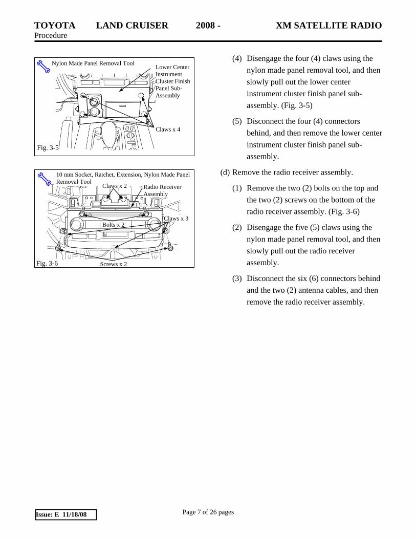
(d) Remove the radio receiver assembly.
(1) Remove the two (2) bolts on the top and the two (2) screws on the bottom of the radio receiver assembly. (Fig. 3-6)
(2) Disengage the five (5) claws using the nylon made panel removal tool, and then slowly pull out the radio receiver assembly.
(3) Disconnect the six (6) connectors behind and the two (2) antenna cables, and then remove the radio receiver assembly.
Nylon Made Panel Removal Tool Lower Center Instrument Cluster Finish Panel Sub-Assembly
Claws x 4
Fig. 3-5
10 mm Socket, Ratchet, Extension, Nylon Made Panel Removal Tool
Bolts x 2
Screws x 2
Radio Receiver Assembly
Fig. 3-6
Claws x 3
Claws x 2

TOYOTA LAND CRUISER 2008 - XM SATELLITE RADIO Procedure
Page 8 of 26 pages Issue: E 11/18/08
4. Removal of Radio Receiver Assembly
(Model without Navigation Display)
NOTE: For models with navigation display please look at page 6.
(a) Remove the speaker opening cover assembly.
(1) Apply masking tape around the speaker opening cover assembly. (Fig. 4-1)
(2) Disengage the eight (8) claws using the nylon made panel removal tool, and then pull out the speaker opening cover assembly upward.
(3) Disconnect the connector of the solar sensor, and then remove the speaker opening cover assembly. (Fig. 4-2)
(b) Remove the radio receiver assembly.
(1) Remove the two (2) screws on the top and the two (2) bolts on the bottom of the radio receiver assembly. (Fig. 4-3)
(2) Disengage the eight (8) claws using the nylon made panel removal tool, and then slowly pull out the radio receiver assembly forward.
(3) Disconnect the five (5) connectors behind, and then remove the radio receiver assembly.
Masking Tape, Nylon Made Panel Removal Tool Claws x 8
Fig. 4-1
Masking Tape
Solar Sensor
Connector
Fig.4-2
Claws x 4 Claws x 4
Bolt
10 mm Socket, Ratchet, Extension, Nylon Made Panel Removal Tool
Screw
Fig. 4-3
Radio Receiver Assembly
Screw
Bolt

TOYOTA LAND CRUISER 2008 - XM SATELLITE RADIO Procedure
Page 9 of 26 pages Issue: E 11/18/08
5. Removal of Vehicle Components
(a) Remove the glove box under panel.
(1) Disengage the four (4) claws, and then remove the glove box under panel. (Fig. 5-1)
(b) Remove the front door scuff plate RH.
(1) Disengage the nine (9) claws using the nylon made panel removal tool, and then remove the front door scuff plate RH. (Fig. 5-2)
(c) Remove the cowl side trim board RH.
(1) Remove the plastic nut on the top of the cowl side trim board RH. (Fig. 5-3)
(2) Disengage the two (2) clips using the nylon made panel removal tool, and then remove the cowl side trim board RH. (Fig. 5-3)
(d) Remove the instrument panel side cover RH.
(1) Disengage the six (6) claws, and then remove the instrument panel side cover RH. (Fig. 5-4)
Nylon Made Panel Removal Tool
Fig. 5-3
Clips x 2 Plastic Nut
Cowl Side Trim Board RH
Glove Box Under Panel
Fig. 5-1 Claws x 4
Front
Push forward
Nylon Made Panel Removal Tool
Claws x 9 Front Door Scuff Plate RHFig. 5-2
Fig. 5-4
Nylon Made Panel Removal Tool
Claws x 6
Instrument Panel Side Cover RH

TOYOTA LAND CRUISER 2008 - XM SATELLITE RADIO Procedure
Page 10 of 26 pages Issue: E 11/18/08
(e) Remove the glove box assembly.
(1) Remove the four (4) bolts from the knee airbag unit under the glove box, and then carefully pull out the knee airbag unit forward so that you can see the connector. (Fig. 5-5) Torque on reassembly 10 N•m (7 lbf•ft).
(2) Disconnect the connector of the knee airbag unit using a fine-tipped screwdriver, and then remove the knee airbag unit. (Fig. 5-6)
(3) Remove the bolt covers on the top of the glove box. Then, remove the two (2) screws on the top and the two (2) screws on the bottom of the glove box. (Fig. 5-7)
(4) Disengage the three (3) claws on the top of the glove box, and then carefully pull out the glove box forward so that it does not drop.
(5) Disconnect the connector of the glove box illumination light, and then remove the glove box. (Fig. 5-8)
Fig. 5-6
Screwdriver
Claws x 2
10 mm Socket, Ratchet, Extension, Nylon Made Panel Removal Tool
Claws x 4
Knee Airbag Unit
Bolts x 4 Fig. 5-5
Phillips Screwdriver, Nylon Made Panel Removal Tool
Screws x 2
Glove Box Assembly Fig. 5-7
Claws
Cover
Cover
Screws x 2
Connector Glove Box Assembly
Fig. 5-8
Cable Straps

TOYOTA LAND CRUISER 2008 - XM SATELLITE RADIO Procedure
Page 11 of 26 pages Issue: E 11/18/08
(f) Remove the navigation ECU.
(Model with Navigation)
(1) Remove the one (1) nut, the one (1) screw on the top and the one (1) screw on the bottom of the navigation ECU. (Fig. 5-9)
(2) Disconnect the connectors of the navigation ECU, and then remove the navigation ECU. (Fig. 5-10)
Navigation ECU Screw
Fig. 5-9
Screw Nut
Phillips Screwdriver, 10 mm Socket, Ratchet, Extension
Navigation ECU
Fig. 5-10
Connectors
TOYOTA LAND CRUISER 2008 - XM SATELLITE RADIO Procedure
Page 12 of 26 pages Issue: E 11/18/08
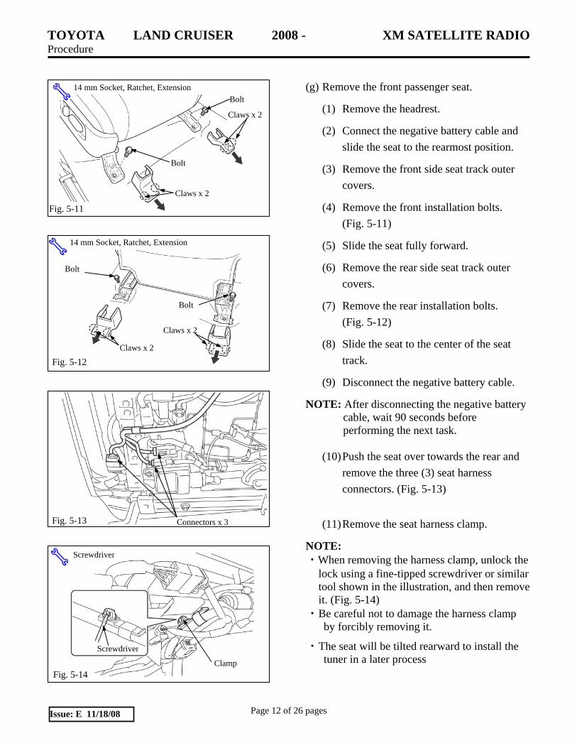
(g) Remove the front passenger seat.
(1) Remove the headrest.
(2) Connect the negative battery cable and slide the seat to the rearmost position.
(3) Remove the front side seat track outer covers.
(4) Remove the front installation bolts. (Fig. 5-11)
(5) Slide the seat fully forward.
(6) Remove the rear side seat track outer covers.
(7) Remove the rear installation bolts. (Fig. 5-12)
(8) Slide the seat to the center of the seat track.
(9) Disconnect the negative battery cable.
NOTE: After disconnecting the negative battery cable, wait 90 seconds before performing the next task.
(10) Push the seat over towards the rear and
remove the three (3) seat harness connectors. (Fig. 5-13)
(11) Remove the seat harness clamp.
NOTE: ・When removing the harness clamp, unlock the
lock using a fine-tipped screwdriver or similar tool shown in the illustration, and then remove it. (Fig. 5-14)
・ Be careful not to damage the harness clamp by forcibly removing it.
・ The seat will be tilted rearward to install the tuner in a later process
Connectors x 3 Fig. 5-13
14 mm Socket, Ratchet, Extension
Fig. 5-12 Claws x 2
Claws x 2
Bolt
Bolt
14 mm Socket, Ratchet, Extension
Fig. 5-11
Claws x 2
Claws x 2
Bolt
Bolt
Clamp
Screwdriver
Screwdriver
Fig. 5-14
TOYOTA LAND CRUISER 2008 - XM SATELLITE RADIO Procedure
Page 13 of 26 pages Issue: E 11/18/08
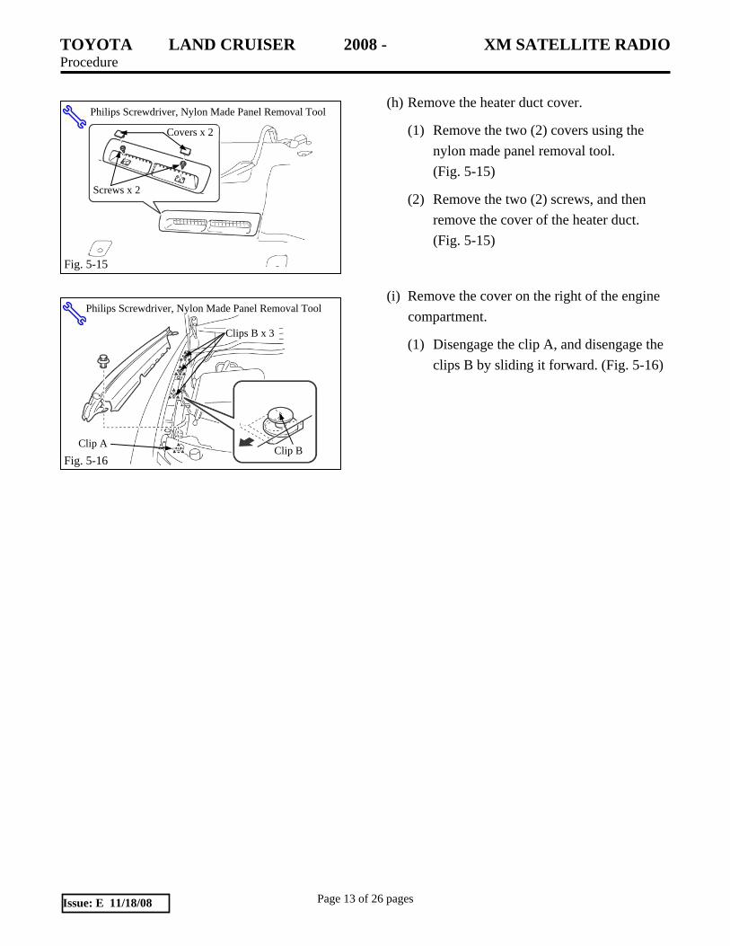
(h) Remove the heater duct cover.
(1) Remove the two (2) covers using the nylon made panel removal tool. (Fig. 5-15)
(2) Remove the two (2) screws, and then remove the cover of the heater duct. (Fig. 5-15)
(i) Remove the cover on the right of the engine compartment.
(1) Disengage the clip A, and disengage the clips B by sliding it forward. (Fig. 5-16)
Clip A
Philips Screwdriver, Nylon Made Panel Removal Tool
Fig. 5-16 Clip B
Clips B x 3
Screws x 2
Covers x 2
Philips Screwdriver, Nylon Made Panel Removal Tool
Fig. 5-15
Screws x 2
Covers x 2

TOYOTA LAND CRUISER 2008 - XM SATELLITE RADIO Procedure
Page 14 of 26 pages Issue: E 11/18/08
6. Antenna Installation and Wiring
Antenna installation and wiring should be performed as shown through the following steps. (Fig. 6-1)
(a) Clean the antenna and cord rails mounting
area with 3M™ Prep Sol-70 and cleaning method. (Fig. 6-2)
(b) When cleaning with 3M™ Prep Sol-70 and cleaning method,
(1) Always use a clean (lint free scratch resistant) soft cloth (or wipe), and clean a small area at a time ( ~ 3 ft. x 3 ft. max.).
(2) Shake well.
(3) Apply 3M™ Prep Sol-70 to cloth or wipe. Do not spray cleaning solution directly on any vehicle surfaces.
(4) Clean surface thoroughly and wipe dry immediately with a new clean cloth. Do not allow cleaner to air dry.
(c) Temporarily place the antenna at the position as shown, and confirm the installation position. (Fig. 6-2)
(d) Attach the cord rails on the right front of the roof. (Fig. 6-3)
NOTE: Make a gap of 5 mm (0.20 in.) between the cord rails to prevent them from coming off because of thermal expansion. (Fig. 6-3)
(e) Remove the release paper from the antenna, and then install the antenna from the roof rail side as shown. (Fig. 6-4)
STOP
STOP
Release Paper
Double-Sided Adhesive Tape
Antenna
Fig. 6-4
Fig. 6-3 5 mm (0.20 in.)
140mm (5.51 in.)
Cord Rail (10mm) Cord Rails x 2 (140 mm)
295 mm (11.61 in.)
Front
5mm (0.20 in.)5 mm (0.20 in.)
140mm (5.51 in.)
Fig. 6-2
Front
Cord Rail
Cord Rail (140mm)
Antenna 15 mm (0.59 in.)
Fig. 6-1
Antenna

TOYOTA LAND CRUISER 2008 - XM SATELLITE RADIO Procedure
Page 15 of 26 pages Issue: E 11/18/08
(f) Bury the antenna cable into the front
windshield weather strip using the panel clip removal tool or tools. (Fig. 6-5)
NOTE: ・Bury the antenna cable all the way into the
weather strip. ・Check for any gaps between the weather strip
and the windshield.
(g) Run the antenna cable from the bottom of the weather strip as shown, and then secure the antenna cable with the two (2) sheet tapes. (Fig. 6-6)
(h) Put the antenna cable through the silicon tube, cross it over the edge as shown, and then secure it with the sheet tape. (Fig. 6-7)
NOTE: When securing the silicon tube with the sheet tape, turn the cut line of the silicon tube sideways.
Antenna Cable
Fig. 6-5
Sheet Tapes x2
Antenna CableFig. 6-6
Front Front
Silicon Tube Sheet Tape
Fig. 6-7

TOYOTA LAND CRUISER 2008 - XM SATELLITE RADIO Procedure
Page 16 of 26 pages Issue: E 11/18/08
(i) Drop the antenna cable through the sponge
part to the bottom of the engine compartment. (Fig. 6-7)
(j) Secure the antenna cable to the vehicle wiring harness in the engine compartment with the two (2) lock ties B. (Fig. 6-8)
(k) Use the side cutter to cut off the excess lock ties length.
(l) Cut off the boot on the “W” side in the engine compartment. (Fig. 6-9)
(m) Insert the antenna cable terminal with the polyurethane cover attached. (Fig. 6-10)
(1) When the antenna cable terminal passes through to the cabin, pull the antenna cable into the cabin.
Boot
Cut off
Side Cutter
Fig. 6-9
Lock Ties B x 2
Side Cutter
Fig. 6-8
Front
Fig. 6-7
Fig. 6-10
Antenna Cable Terminal Polyurethane Cover

TOYOTA LAND CRUISER 2008 - XM SATELLITE RADIO Procedure
Page 17 of 26 pages Issue: E 11/18/08
(n) Prevent water intrusion to the cabin.
(1) Pull the antenna cable a little back to the engine compartment, and then define the position to secure with slack in the antenna cable as shown. (Fig. 6-11)
(2) Pull the antenna cable a little paying attention not to pull the antenna cable terminal back to the engine compartment. Then, wrap the butyl sheet (15 x 15 mm, 0,59 x 0.59 in.) around the predefined position to secure. (Fig. 6-12)
(3) Apply the silicon glue on the outside of the butyl sheet, and then insert the antenna cable into the boot again. (Fig. 6-12)
(4) Apply more silicon glue from the outside to make the boot hole airtight. (Fig. 6-13)
(5) Secure the antenna cable to the vehicle wiring harness in front of the boot with the lock tie B. (Fig. 6-13)
(6) Use the side cutter to cut off the excess lock tie length.
(o) Wiring in the cabin
(1) Secure the antenna cable at the position as shown with the sheet tape.
(2) Secure the antenna cable to the vehicle wiring harness under the glove box with the lock tie B. (Fig. 6-14)
(3) Use the side cutter to cut off the excess lock ties length.
NOTE: For the rest of the installation procedures, see step (e) on page 20.
Fig. 6-14 Lock Tie B
Sheet Tape Side Cutter
Fig. 6-11
Fig. 6-12
Silicon Glue
Butyl Sheet
Antenna Cable
Fig. 6-13 Lock Tie B
Side Cutter Silicon Glue

TOYOTA LAND CRUISER 2008 - XM SATELLITE RADIO Procedure
Page 18 of 26 pages Issue: E 11/18/08
7. Wire, to Radio Installation (Tuner Cable)
Wiring
(a) Wiring between the radio and the glove box
(1) Pass the tuner cable through to the glove box from the position on the cowl side as shown in the figure. (Fig. 7-1)
(2) Run it along the tuner cable on the rear
of the reinforcement bar of the upper blowers. (Fig. 7-2)
(b) Center part of instrument panel (Navigation model)
(1) Pull the tuner cable from where the glove box is installed as shown in the figure. (Fig. 7-3)
(2) Align the branching point of the tuner cable to the branching point of the vehicle wiring harness, and then secure them with one (1) lock tie A. (Fig. 7-3)
(3) Connect the tuner cable to the radio harness. (Fig. 7-4)
(4) Secure the tuner cable to the radio harness with one (1) lock tie A. (Fig. 7-4)
(5) Use the side cutter to cut off the excess two (2) lock ties length.
(6) Wrap cushion tape around the connections.
NOTE: Roll up the cushion tape on the harness with the connector fixed using the lock tie A. (Fig. 7-4)
Side Cutter
Fig. 7-4
Tuner Cable
Lock Tie A
Cushion Tape
Fig. 7-1
Tuner Cable
Fig. 7-2
Tuner Cable
Fig. 7-3
Tuner Cable
Lock Tie A

TOYOTA LAND CRUISER 2008 - XM SATELLITE RADIO Procedure
Page 19 of 26 pages Issue: E 11/18/08
(7) Secure the tuner cable with the two (2)
lock ties A. (Fig. 7-5)
(8) Use the side cutter to cut off the excess lock ties length.
(9) Set the tuner and connect the disconnected connectors and tuner cable to their original positions. (Fig. 7-6)
(c) Center part of instrument panel (Audio model)
(1) Secure the tuner cable with the two (2) lock ties A. (Fig. 7-7)
(2) Use the side cutter to cut off the excess lock ties length.
(3) Wrap cushion tape around the female connector.
(4) Secure the tuner cable with the three (3) lock ties A. (Fig. 7-8)
(5) Use the side cutter to cut off the excess lock ties length.
Fig. 7-8
Lock Ties A x 3
Side Cutter
Cushion Tape
Fig. 7-7
Side Cutter
Lock Ties A x 2
Fig. 7-6
Tuner Cable
Fig. 7-5
Lock Ties A x 2
Side Cutter

TOYOTA LAND CRUISER 2008 - XM SATELLITE RADIO Procedure
Page 20 of 26 pages Issue: E 11/18/08
(6) Connect the tuner cable to the audio unit,
and then connect the disconnected connectors to their original positions. (Fig. 7-9)
(d) Glove box installation area (Audio model and navigation model)
(1) Secure the tuner cable with the four (4) lock ties A. (Fig. 7-10)
(2) Use the side cutter to cut off the excess lock ties length.
NOTE: Avoid contact of the tuner cable with any edges.
(e) Wiring between the glove box and the front
door scuff plate (Joined with the antenna cable)
(1) Secure the tuner cable with the three (3) lock ties A. (Fig. 7-11)
(2) Use the side cutter to cut off the excess lock ties length.
(f) Wiring between the front door scuff plate and
the passenger seat
(1) Carefully tilt the passenger seat rearward to access the floor carpet. (Fig. 7-12)
Fig. 7-12
Floor Carpet
Fig. 7-9
Tuner Cable
Joining Point of Antenna Cable
Fig. 7-11
Lock Ties A x 3
Side Cutter
Lock Ties A x 2
Fig. 7-10
Side Cutter
Edges Lock Tie A
Lock Tie A

TOYOTA LAND CRUISER 2008 - XM SATELLITE RADIO Procedure
Page 21 of 26 pages Issue: E 11/18/08
(2) Run the tuner cable and the antenna
cable along the vehicle wiring harness as shown in the illustration. (Fig. 7-13)
(3) Secure the three (3) positions with the lock ties A, and secure the three (3) positions with the lock ties B.
(4) Use the side cutter to cut off the excess lock ties length.
8. Receiver Assembly Radio (Tuner) Connection
and Installation
(a) Attach the tuner to the tuner brackets A and B. (Fig. 8-1)
(b) Install the tuner on the vehicle body (bottom front on the passenger’s side.)
(1) Clean the bracket B mounting surface of the vehicle floor pan and the bracket B with 3M™ Prep Sol-70.
(2) Apply a butyl sheet (38 x 38mm, 1.50 x 1.50 in.) on the floor pan. (Fig. 8-2)
(3) Place the tuner in the predefined position.
(4) Fasten the bracket A with the two (2) bolts. (Fig. 8-3)
(5) Pull out the separator of the butyl sheet. (Fig. 8-3)
(6) Apply pressure on the bracket B from above.
10 mm Socket, Ratchet, Extension
Fig. 8-3
Separator
Fig. 8-1 Tuner Bracket A
Screws x 2
Tuner
Phillips Screwdriver
Screws x 2
Tuner Bracket B
Separator
Fig. 8-2
Butyl Sheet
Vehicle Wiring Harness Clamps Fig. 7-13
Lock Ties A x 3
Side Cutter
Lock Ties B x 3
Lock Tie A
Lock Tie B Tuner Cable
Antenna Cable
Vehicle Wiring Harness
TOYOTA LAND CRUISER 2008 - XM SATELLITE RADIO Procedure
Page 22 of 26 pages Issue: E 11/18/08
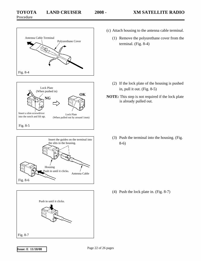
(c) Attach housing to the antenna cable terminal.
(1) Remove the polyurethane cover from the terminal. (Fig. 8-4)
(2) If the lock plate of the housing is pushed in, pull it out. (Fig. 8-5)
NOTE: This step is not required if the lock plate is already pulled out.
(3) Push the terminal into the housing. (Fig. 8-6)
(4) Push the lock plate in. (Fig. 8-7)
Push in until it clicks.
Fig. 8-7
Fig. 8-5
Lock Plate (When pushed in)
Lock Plate (When pulled out by around 1mm)
OKNG
Insert a slim screwdriver into the notch and lift up.
Fig. 8-4
Antenna Cable Terminal Polyurethane Cover
Fig. 8-6
Antenna Cable
Housing Push in until it clicks.
Insert the guides on the terminal into the slits in the housing.

TOYOTA LAND CRUISER 2008 - XM SATELLITE RADIO Procedure
Page 23 of 26 pages Issue: E 11/18/08
(d) Connect the antenna cable to the tuner. (Fig. 8-8)
(1) Connect the antenna connector to the tuner, and then secure the connection with the one (1) sheet tape.
(e) For model without RSE (Rear Seat Entertainment System), connect the tuner cable to the tuner. (Fig. 8-9)
(f) For RSE (Rear Seat Entertainment System) model, connect the tuner cable to the tuner. (Fig. 8-10)
(1) Connect the connectors C and D to the XM tuner.
(2) Disconnect the connector E from the RSE controller. Instead, connect the connector A to the RSE controller.
(3) Connect the connector B to the
connector E, and then secure them to the tuner cable with the lock tie A. (Fig. 8-11)
Fig. 8-10
Connector A
Connector B
Connector C, D
Connector E
Sheet Tape
Fig. 8-8
Antenna Cable
Fig. 8-9
Connector
Fig. 8-11
Connector A
Connector B
Lock Tie A
Connector E
Front
TOYOTA LAND CRUISER 2008 - XM SATELLITE RADIO Procedure
Page 24 of 26 pages Issue: E 11/18/08
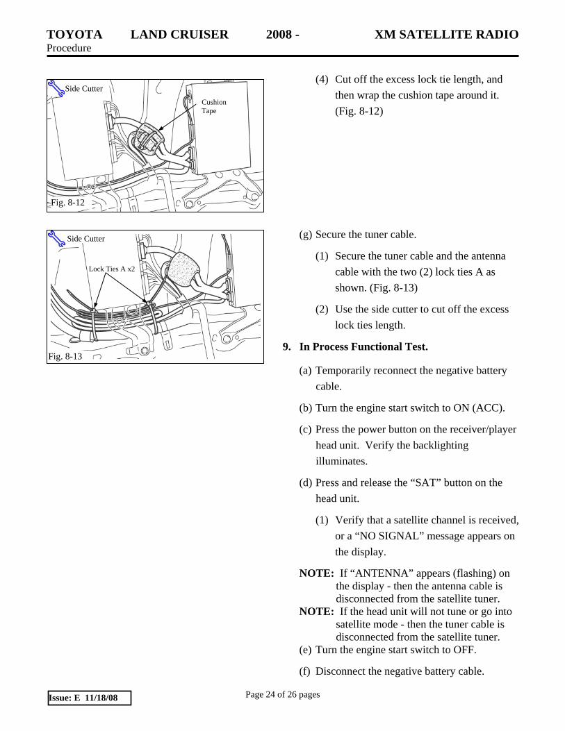
(4) Cut off the excess lock tie length, and
then wrap the cushion tape around it. (Fig. 8-12)
(g) Secure the tuner cable.
(1) Secure the tuner cable and the antenna cable with the two (2) lock ties A as shown. (Fig. 8-13)
(2) Use the side cutter to cut off the excess lock ties length.
9. In Process Functional Test.
(a) Temporarily reconnect the negative battery cable.
(b) Turn the engine start switch to ON (ACC).
(c) Press the power button on the receiver/player head unit. Verify the backlighting illuminates.
(d) Press and release the “SAT” button on the head unit.
(1) Verify that a satellite channel is received, or a “NO SIGNAL” message appears on the display.
NOTE: If “ANTENNA” appears (flashing) on the display - then the antenna cable is disconnected from the satellite tuner.
NOTE: If the head unit will not tune or go into satellite mode - then the tuner cable is disconnected from the satellite tuner.
(e) Turn the engine start switch to OFF.
(f) Disconnect the negative battery cable.
Side Cutter
Fig. 8-12
Cushion Tape
Side Cutter
Fig. 8-13
Lock Ties A x2

TOYOTA LAND CRUISER 2008 - XM SATELLITE RADIO Procedure
Page 25 of 26 pages Issue: E 11/18/08
10. Complete the Reassembly of Vehicle.
(a) Reconnect any disconnected connectors.
(b) Reinstall the front seat. (Fig. 10-1, Fig. 10-2)
(1) Reinstall the four (4) bolts loosely, and then tighten them in the following order: Rear inner bolt Rear outer bolt Front inner bolt Front outer bolt
(2) Tighten bolts to 42 N•m (32 lbf•ft)
(c) Verify the panels fit together properly with
no uneven gaps between them.
(d) Clean up and remove any trash.
(e) Place the owner “XM Satellite Radio” brochure in the glove box.
11. Reconnect Negative Battery Cable
(a) Reconnect the vehicle’s negative battery cable (Fig. 11-1).
(1) Position the negative terminal to the battery as shown (original factory position).
(2) Tighten the nut to 4.1 N•m (36 lbf•in).
(3) Do not touch the positive terminal with any tool when replacing the cable.Fig. 11-1 Battery
10 mm Socket, Torque Wrench Negative Battery Cable
90°
Fig. 10-1
14 mm Socket, Torque Wrench, Extension
Fig. 10-2
14 mm Socket, Torque Wrench, Extension

TOYOTA LAND CRUISER 2008 - XM SATELLITE RADIO Checklist - these points MUST be checked to ensure a quality installation.
Check: Look For:
Page 26 of 26 pages Issue: E 11/18/08
Accessory Function Checks
Satellite radio
Audio head unit
Navigation system
Vehicle Function Checks
Hazard switch
Passenger’s seat belt reminder light
Removed seat
Seat lock mechanism and power seat
operation
SRS warning light
HVAC (heating ventilation and air conditioning) system
SSP function
Instrument panel switches functions (Any electrical connector removed in this manual)
Verify the proper operation of the satellite radio.*
Verify the proper operation of the audio head unit.* *: Refer to the XM Satellite Radio Brochure and audio head unit owner’s manuals. Execute DTC check, and confirm there is no error. (Refer to the LAND CRUISER Repair Manual.)
Proper operation of the hazard switch.
Proper operation of the passenger’s seat belt reminder light.
Verify the removed seat is securely fastened.
Verify the proper operation of the removed seat lock mechanism and power seat system.
Verify the SRS warning light illuminates for approximately 6 seconds with the engine/start switch ON, and then goes out.
Proper operation of the air conditioning system.
Verify the radio SSP function by pressing the "SSP" button on the audio head unit for 5 seconds.
Verify the proper operation of the instrument panel switches functions.