TOWN OF PORT MCNEILL Bylaw 414 FINAL
221
1 TOWN OF PORT MCNEILL Bylaw #414 SUBDIVISION AND DEVELOPMENT BYLAW
Transcript of TOWN OF PORT MCNEILL Bylaw 414 FINAL

1
TOWN OF PORT MCNEILL
Bylaw #414
SUBDIVISION AND DEVELOPMENT BYLAW

2
BYLAW No. 414 – TABLE OF CONTENTS
SECTION 1 INTERPRETATION .................................................................................. 7
101 Title.............................................................................................................................. 7
102 Definitions................................................................................................................... 7
SECTION 2 ADMINISTRATION ................................................................................ 11
201 Approving Officer................................................................................................ 11
202 Approval Procedure............................................................................................. 11
203 Application for Preliminary Layout Approval for Subdivision ....................... 12
204 Preliminary Layout Approval ............................................................................ 13
205 Design Approval................................................................................................... 15
206 Application for Final Approval ........................................................................... 16
SECTION 3 DESING AND CONSTRUCTION REQUIREMENTS........................ 17
301 Service Levels ...................................................................................................... 17
302 Design................................................................................................................... 17
303 Construction Requirements ............................................................................... 17
304 Storm Water Drainage ....................................................................................... 19
305 Provision of Parkland at Time of Subdivision ................................................. 19
SECTION 4 DEVELOPMENT OF LAND ................................................................. 19
401 Conditions of Issuance of a Building Permit .................................................... 19
403 Design Approval.................................................................................................. 20
404 Application for Building Permit ........................................................................ 20
SECTION 5 GENERAL PROVISIONS....................................................................... 21
502 Application........................................................................................................... 21
502 Prohibition........................................................................................................... 21
503 Subdivisions Where Servicing Requirements May be Waived....................... 21
504 Cost of Services ................................................................................................... 22

3
505 Completion of Works and Services ................................................................... 22
506 Excess or Extended Service and Latecomer Payments ................................... 24
507 Violation and Penalty ......................................................................................... 24
508 Indemnification ................................................................................................... 24
509 Schedules Form Part of Bylaw........................................................................... 25
511 Effective Date ...................................................................................................... 25
SCHEDULES
Schedule “A” List of Approved Design Drawings ....................................................... 26
Schedule “B” Certificate of Completion....................................................................... 27
Schedule “C” Certificate of Satisfaction....................................................................... 28
Schedule "D" Servicing Levels ...................................................................................... 29
Schedule "E" Application for Preliminary Layout Approval for Subdivision......... 30
Schedule "F" Application for Approval of Desing Drawings.................................... 33
Schedule “G” Appication for Final Approval of Subdivision Plan............................ 35
Schedule “H” Development Works Specifications....................................................... 35
Schedule “I” Section 911 Servicing Agreement ........................................................ 202
Schedule “J” Irrevocable Letter of Credit ................................................................. 214
Schedule “K”Warranty Agreement ............................................................................ 216
Schedule “L” Statutory Right-of-Way Agreement.................................................... 219

4
SUBDIVISION BYLAW NO. 414
INDEX TO SCHEDULE “H” FOR DEVELOPMENT WORKS SPECIFICATIONS
Section Page General Introduction A-1 1 Development Procedures and Policies A-2 1-5 Design Drawings B-1 1-6 As Constructed Drawings B-2 1-3 Design of Sewers and Drains SD-1 1-6 Installation of Sewers and Drains SD-2 1-5 Design of Waterworks W-1 1-5 Installation of Waterworks W-2 1-5 Trench Excavation, Backfilling & Cleanup T-1 1-2 Design of Roads and Sidewalks R-1 1-7 Construction of Roads and Sidewalks R-2 1-10 SCHEDULE H Appendix 1 – Asphaltic Materials R-2 1-10 Appendix 2 – Base and Sub-base Preparation R-2 1-5 Appendix 3 – Surface Preparation for Asphalt Paving R-2 1-5 Appendix 4 – Asphaltic Concrete Paving R-2 1-15 Appendix 5 – Surface Treatment R-2 1-8 Appendix 6 – Asphalt Testing and Inspection R-2 1-3 Appendix 7 – Methods of Testing Asphalt R-2 1-3 Appendix 8 – Concrete R-2 1-5 STANDARD DRAWINGS Drawing Number Rainfall Intensity Duration Chart A1 Trench Conditions above the Pipe Zone T1 Standard Manhole for up to & Including 375mm Pipe SD1 Drop Manhole SD2 Cleanout SD3 200mm Manhole Cover & Frame SD4

5
Index to Schedule “H” Continued Standard Drawings Drawing Number 100mm Manhole Cover & Frame SD5 General Service Connection Details Drain & Sewer SD6 Service Connection Details Drain & Sewer SD7 Classes of Pipe Beddings for Sewer & Water SD8 Silt Trap SD9 Rectangular Catch Basin (for use with Curb & Gutter) SD10 Double Catch Basin (for use with curb & gutter) SD11 Square Catch Basin SD12 Rectangular Catch Basin Frame & Grate SD13 Square Catch Basin Frame & Grate SD14 Combination Silt Trap & Grease Interceptors SD15 Thrust Blocks W1 Fire Hydrant Assembly W2 19mm Air Valve Assembly W3 2 ½” Standpipe Assembly W4 N.T. (Nelson Type) Valve Box W5 19mm & 25mm Water Service Connection W6 Classes of Pipe Bedding W7 39mm Water Service Connection W8 50mm Water Service Connection W9 Typical Cross Section 8.5m Residential Road R1 Typical Road Cross Section R2 Typical Location of Works 20m R/W R3 Typical Cul-de-sacs R4 Temporary Turn-around Details R5 Driveway Grades R6 Vertical Curves for Minimum Stopping Sight Distance R7 Superelevation R8 Mountable Curb (Wide Section) & Invert Gutter R9 Mountable Curb (Narrow Section) & Curb Reinforcing at Catch Basins R10 Non-mountable Curb R11 Concrete Sidewalk R12 Asphalt Sidewalk R13 Sidewalk Driveway Crossing R14 Sidewalk Corner Ramp R15 Barricades R16 Chain Link Fence R17 Sidewalk Handrails R18 Concrete Gravity Retaining Wall R19 Rock Masonry Retaining Wall R20 Concrete Cantilever Retaining Wall Type A R21

6
Index to Schedule “H” Continued Standard Drawings Drawing Number Concrete Cantilever Retaining Wall Type B R22 Street Light Standard R23 Street Light & Traffic Signal Standard Bases R24 Street Name Standard R25 Standard Road Closure R26 Major Street Driveway Signing R27 Traffic Signal Standard R28
7
TOWN OF PORT MCNEILL
BYLAW NO. 414
A Bylaw to regulate the subdivision and development of land within the Town of Port McNeill
AND WHEREAS Sections 989, 990, 991, 992, 993, 994, 995 and 996 of the Municipal Act, Chapter 290 of the Revised Statutes of British Columbia 1979, as amended, empower the Council to regulate the subdivision and development of land; AND WHEREAS the Land Title Act, Chapter 219, Revised Statutes of British Columbia 1979, as amended, provides for the subdividing of land; AND WHEREAS it is deemed expedient and in the public interest to regulate the subdivision of land, and to define the works and services required as a condition of issuance of a building permit; NOW THEREFORE the Council of the Town of Port McNeill, in open meeting assembled, enacts as follows: SECTION 1 INTERPRETATION 101 Title
This bylaw may be cited as the “Subdivision and Development Bylaw”, and is further referred to herein as “this bylaw”.
102 Definitions
(1) In this bylaw, unless the context otherwise requires, the following words and phrases shall have the following meanings: “Applicant” means the person applying for the approval of a subdivision whether as the owner of the property proposed to be subdivided or as a duly authorized agent for the owner and with the owner’s permission. “Approval, Final” means the Approving Officer’s affixing his signature to the subdivision plan pursuant to Section 88 of the Land Title Act. “Approval, Preliminary Layout” means written notification of a review of information presented to the Approving Officer previous to submission of a subdivision plan for final approval.

8
“Approving Officer” means any person duly authorized by the Town Council to act as Approving Officer pursuant to the provisions of the Land Title and Municipal Acts. “Area” means the total horizontal area within the boundaries of a lot created by subdivision. “Boulevard” means that portion of a highway between the curb lines or the lateral boundary lines of a roadway and the adjoining property or between curbs on median stripes or islands, but does not include curbs, sidewalks, ditches or driveways. “Clerk” means the Clerk of the Town of Port McNeill. “Community Sewer System” means a common sewer or system of sewerage or sewage disposal which serves two or more parcels and is owned, operated and maintained by the Town under the Municipal Act. “Community Water System” means a system of waterworks which serves two or more parcels and which is owned, operated and maintained by the Town under the Municipal Act. “Consulting Engineer” means a professional Engineer, registered in the Province of British Columbia, who is retained by the Owner or Applicant. “Construction” shall mean the construction or installation of all works required by this bylaw. “Contractor” means a subdivider or his contractor who constructs services and roads for a parcel or parcels of land. “Corporation, Town, or Municipality” means the Town of Port McNeill, or the area within the town boundaries thereof or amended boundaries as the context may require. “Council” means the Municipal Council of the Town of Port McNeill. “Cul-de-sac” means a street having access to another street at one end only. “Developer” means the subdivider or the holder of a building permit or his contractor or his agent appointed in writing.

9
“Development” means a change in the use of land or in the nature of the use of land, and may include, but is not limited to,
(a) Subdivision of land under the Land Title Act; (b) Construction or placement of buildings and structures on land pursuant to a building permit; or (c) Both.
“Frontage” means that boundary of a parcel boundary which immediately adjoins a highway other than a lane or walkway. “Highway” means a street, road, lane, bridge, viaduct, and any other way open to the use of the public, but does not include a private right-of-way on private property. “Installed” means constructed. “Land Surveyor” means a person qualified to carry out legal land surveys who are registered as a British Columbia Land Surveyor. “Lane” means a road allowance more than 6 meters (19.69 feet) and less than 10 meters (32.81 feet) in width used exclusively for the collection of garbage, loading and unloading of vehicles. “Local Street” means any street other than a collector street or arterial street intended to serve properties abutting it, not intended to carry traffic from one neighbourhood to another neighbourhood or from one use area to a similar use area. “Lot” means a parcel of land registered in the Land Title Office. “Lot Depth” means the mean average horizontal distance between the front and rear lot lines. “Lot Line” means the legally defined boundary of any lot. “Lot Width” means the mean horizontal distance between side lot lines measured at right angles to the lot depth. “Medical Health Officer” means the Medical Health Officer appointed pursuant to the Health Act. “Municipal Engineering Advisor” means a professional engineer, registered in the Province of British Columbia, who is retained by the Town of Port McNeill. “Owner” and “Registered Owner” where used in the bylaw and in addition to its accepted meaning as set out in the Land Title Act, Chapter 219, RSBC 1979 as

10
amended, includes an individual, an association, a partnership or an incorporated company or corporation and whenever the singular is used herein, it shall be construed as including the plural. “Panhandle Lot” means any lot which is serviced and gains highway frontage through the use of a narrow strip of land which is an integral part of the lot. “Parcel” means any lot, block or other area in which land is held or into which land is subdivided and for which a separate Certificate of Title might be issued. “Potable Water” means water which is approved for drinking purposes by the Medical Health Officer in accordance with the Health Act. “Professional Engineer” means a person who is registered to practice in the Province of British Columbia and duly licensed as such under the provisions of the Engineers and Geoscientists Act. “Roadway” means the portion of the highway that is improved, designed or ordinarily used for vehicular traffic. “Services” means works required to service a subdivision in accordance with Schedule “A”. “Slip” means the downward and outward movement of slope-forming materials composed of natural rock, soils, artificial fills, or combinations of these materials, which movement may proceed by any of the three principal types of movement -falling, sliding or flowing- or by their combinations. “Street” means a public highway having a right-of-way width of ten meters or more. “Subdivision” means the division of land into two or more parcels, whether by plan, apt descriptive words, or otherwise. “Utility” means any water main, sewer main, pipeline, power line, underground conduit or drainage facility. “Walkway” means a public way restricted to pedestrian use. “Watercourse” means any natural or man-made depression with well-defined banks and a bed zero point six (0.6) meters or more below the surrounding land serving to give direction to a current of water at least six months of the year, or having a drainage area of two square kilometers or more upstream of the point of consideration, or as required by a designated official of the Ministry of Environment of the Province of British Columbia. “Works” means all construction or installation necessary to comply with this bylaw.

11
“Zone” means a zone established under Section 963 of the Municipal Act. “Zoning Bylaw” means a bylaw governing the use of land adopted by the Council pursuant to the Municipal Act.
(2) All other words, terms and expression in this bylaw shall be as defined by the Land Title Act, the Municipal Act and the Interpretation Act.
SECTION 2 ADMINISTRATION 201 Approving Officer
(1) The Approving Officer shall refuse to approve the subdivision of any parcel of land unless all the relevant requirements of this bylaw, the Municipal Act and the Land Title Act and other relevant statues have been observed.
(2) The Approving Officer or such other person as the Council may Designate, may enter at all reasonable times upon the land for which an application to subdivide has been made for the purpose of administering or enforcing this bylaw.
(3) No person shall prevent or obstruct any such official from the carrying out of his
duties under this bylaw. (4) The Approving Officer shall maintain a permanent record of all subdivision
applications submitted under this bylaw.
(5) Where improvements have been required, the Approving Officer shall satisfy himself that such improvements have been made in conformity with Town specifications and that the drawings of the complete improvements truly represent the improvements installed or adequate security has been made as required under this bylaw.
(6) The authority of the Approving Officer to approve applications for the subdivision of land is governed by Sections 85, 86 and 87 of the Land Title Act.
202 Approval Procedure
The subdivision approval procedure of this bylaw is briefly summarized as follows:
(a) An application is submitted by the owner for preliminary layout approval;
(b) Approving Officer issues a preliminary layout approval;
(c) Consulting engineer provides a letter of assurance;

12
(d) Engineering drawings for all works and services, prepared by a Professional Engineer, submitted by the owner for approval;
(e) Municipal Engineering Advisor or Approving Officer approves engineering
drawings;
(f) Either construction is completed of works and services, “as constructed” drawings are submitted by the owner, and acceptance of the work given by the Town, or the owner deposits a security with the Town and signs a Section 991 Agreement with the Town;
(g) Legal survey is posted on the ground and legal survey plans prepared by a
registered British Columbia Land Surveyor;
(1) Plan of subdivision submitted by owner for final approval;
(2) Plans of Statuary rights-of-way and agreements submitted by owner for signature.
(h) Warranty agreement and security submitted by owner; (i) Approving Officer gives Final Approval by signing plan of subdivision
(j) Owner submits legal plans and agreements to the Land Title Office for
registration;
(k) Town releases securities in accordance with Agreements. 203 Application for Preliminary Layout Approval for Subdivision
(1) The applicant may request a preliminary layout approval of any proposed alteration of lot lines or subdivision of any existing parcel before applying for final approval.
(2) Every application for Preliminary Layout Approval shall be tendered in writing in the applicable form prescribed in Schedule “E” and forming part of this bylaw, and shall contain the following information: (a) The name and postal address of the applicant and the full legal
description and location of the lands to be subdivided;
(b) Four copies of a sketch plan drawn to a scale of not less than 1:1000, clearly indicating:

13
(i) The location, dimensions, areas and boundaries of existing parcels to be subdivided and the boundaries, dimensions and areas of the lots to be created;
(ii) The arrangement of the parcels of land and of the streets which will be
created by the subdivision, including the widths of the proposed streets and the approximate dimensions of the proposed parcels of land;
(iii) The relationship of the proposed subdivision to adjoining or adjacent
streets and the connections of proposed new streets thereto;
(iv) The scale of the plan and the direction of north thereon;
(v) The anticipated use of the lands being subdivided;
(vi) The locations and dimensions of all buildings and structures, showing setbacks from property lines; and
(vii) The location of creeks, water courses, swamps, ravines, steep slopes
and other pertinent topographic features;
(c) A certificate of approval in accordance with Clause 9.0 of Section A-2 of
Schedule “H” for lands proposed to be serviced by ground disposal of sewage; and
(d) Evidence that the applicant is the owner of the land or that he has been
authorized by the owner to make an application under this bylaw.
(3) Where the parcels of land created by a proposed subdivision do not adjoin existing municipal services, the owner shall be required to submit to the Approving Officer a feasibility report prepared by a qualified engineer or other person acceptable to the Approving Officer setting out all improvements for servicing the parcels of land pursuant to the standards prescribed in Schedule “D” and forming part of this bylaw.
204 Preliminary Layout Approval
(1) The Approving Officer shall examine the preliminary application and shall advise the applicant in writing within 60 days of the date of tender:
(a) That the proposed subdivision will be approved subject to the provisions
contained in this bylaw governing an application for final approval; or (b) That the proposed subdivision may be approved subject to such conditions or
modifications as the Approving Officer may prescribe; or

14
(c) That the preliminary approval cannot be considered until the owner supplies to the Approving Officer such additional information or assurance as the Approving Officer shall require; or
(d) That the proposed subdivision is rejected, setting out the reasons for his
decision.
(2) Approval given to a preliminary application shall be known as Preliminary Layout Approval.
(3) Preliminary layout approval shall not be construed as:
(a) Approval for land registration; or (b) Application for subdivision under Section 993 of the Municipal Act; or (c) Final approval of such subdivision; or (d) Acceptance by the Town or its Approving Officer of anything except the
general layout of the proposed subdivision and a list of minimum conditions which would be taken into consideration on an application for approval under Section 83 through 90 of the Land Title Act.
(4) Preliminary layout approval shall expire 180 days from the date such approval was
granted, unless upon application of the owner or his agent, an extension is granted by the Approving Officer for further periods each of not more than 90 days.
(5) If the Approving Officer has reason to anticipate a further subdivision of the relevant
lands, the applicant, at the request of the Approving Officer, shall furnish a sketch plan showing the ultimate method of subdivision and showing how the present step fits into such ultimate subdivision.
(6) The Approving Officer may require the applicant to furnish a conceptual design of
trunk water main, sanitary sewer and drain facilities if the subdivision is the first or intermediate step of an ultimate subdivision of the relevant land.
(7) The Approving Officer may require the applicant to furnish profiles of every
proposed new street and such topographical details as necessary to indicate the engineering problems to be dealt with in designing or constructing streets or lanes.
(8) Where unusual soil or drainage conditions exist on part or all of the lands to be
subdivided, the Approving Officer may require the applicant to furnish such information as will enable the Approving Officer to determine the area, shapes and orientations of parcels which will be adequate in view of the nature of the ground and anticipated use of the land.

15
(9) If the expressed or obvious intention of the application for approval involves the established of a boundary or boundaries in reconciliation with the existing buildings on the affected parcels or where the position of a proposed new boundary is controlled by the location of such buildings and in all cases where the proposed boundary establishment cannot be sufficiently identified on the ground by inspection, the Approving Officer may on the ground by inspection, the Approving Officer may require the owner to produce a plan or sketch, verified by a Land Surveyor, showing the proposed new boundary or boundaries in relation to the affected parcels and to the buildings thereon.
(10) The Approving Officer may require the owner to produce a plan or sketch, verified by
a Land Surveyor to show any:
(a) building; (b) structure; (c) water course; and (d) high bank which is located on the lands to be subdivided, or adjacent lands.
The sketch or plan will show the location in relation to the lot line of the parcel in which they are situated.
(11) Where a proposed subdivision borders on a Controlled Access Highway, the
Approving Officer shall notify the Regional Engineer for the Ministry of Transportation and Highways of the proposal at the time of application for preliminary layout approval.
205 Design Approval
(1) The applicant shall tender the design drawings and specifications together with an application in writing in the applicable form prescribed in Schedule “F” and forming part of this bylaw. These shall be accompanied by the letter required by Clause 4.04 of Section A-2 of Schedule “H” of this bylaw, any applications to Senior Governments requiring the signature of the Municipality, and the Town’s fees for having the design drawings and specifications examined by the Municipal Engineering Advisor.
(2) The Approving Officer shall examine the design drawings and specifications and
shall advise the applicant in writing within 60 days of the date of tender:
(a) That the design drawings and specifications are approved or
(b) That the design drawings and specifications require amendment and resubmission.

16
206 Application for Final Approval
(1) The final subdivision shall conform substantially to the approved preliminary plan, but the application for final approval need not necessarily cover the whole project in one application. If the subdivision project is submitted in sections, a separate application may be made covering each section.
(2) An application shall be made on the applicable form prescribed in Schedule “G” and
forming part of this bylaw. (3) Early application for final approval of a subdivision:
(a) Payment to the Town of all fees and applicable Development Cost Charges payable for the subdivision and the costs of all construction work required to be done by the Town.
(b) Payment to the Town of all the Town’s costs of connecting all utilities to
serve the proposed subdivision; (c) A Certificate from the Town that all taxes which have been assessed on the
lands to be subdivided have been paid; (d) All legal subdivision plans; (e) The as-constructed drawings, duly certified as required by Clause 2.03 of
Section B-2 of Schedule “H”; (f) Schedule “K”, the Warranty Agreement. (g) The security required by the Warranty Agreement; (h) Any Statutory right-of-way plans and Agreements required; (i) Copies of all senior government certificates, permits, instructions and
comments. (j) All other documents required by Schedule “G”.
(5) Where a subdivision plan is tendered for examination and approval after the
expiration of three months from the date of the completion of the survey, the Approving Officer may require that the surveyor inspect the survey and satisfy himself that all posts and monuments are in place and that the survey has not been affected by any intervening survey or right-of-way location, and certify that same on the plan by the work “inspected” with the date and his signature. The surveyor may so inspect and certify before the plan is tendered for approval.

17
(6) No person shall amend any approved plan of subdivision or any approved design drawings or specifications without first having obtained the approval therefor in writing from the Approving Officer.
Section 3 DESIGN AND CONSTRUCTION REQUIREMENTS 301 Service Levels All subdivisions shall be provided with services as prescribed in Schedule “D” of this bylaw. 302 Design
(1) Lot size, width, depth, shape and orientation shall be appropriate for the location and contemplated use of the subdivision, shall conform to the minimum requirements for the respective zones as listed in the Zoning Bylaw and amendments thereto.
(2) Notwithstanding Subsection (1), pursuant to Section 994 of the Municipal Act the
Approving Officer may exempt a parcel from the prescribed minimum frontage requirements.
303 Construction Requirements
(1) Where any parcel is to be subdivided, all works and services to be provided shall be located and constructed as prescribed in Schedule “H”, Development Works Specifications, and at the sole expense of the owner including:
(a) Roadways and widening of existing roadways immediately adjacent to the
subdivision and up to the centre line of the existing highway; (b) Sidewalks; (c) Boulevards; (d) Boulevard crossings; (e) Transit bays; (f) Street lighting; (g) Underground wiring; (h) Water distribution and fire hydrant system; (i) Sewage collection and disposal system; and (j) Drainage collection and disposal system.

18
(2) All new highways within the subdivision, including widening strips of existing
highways, cul-de-sacs, lanes and walkways shall have the dimensions, locations, alignment and gradient prescribed by Schedule “H”, Development Works Specifications and:
(a) The arrangement of streets shall conform in general alignment to any
applicable municipal bylaw and the Official Community Plan; (b) Proposed street alignment shall be sufficient and suitable as determined by the
Approving Officer for the anticipated traffic volume and land contours, not only within the area being subdivided, but to the street system already established or which may be required to provide access to the lands lying beyond or around and to the general street pattern of the Town;
(c) Where a subdivision borders on a Controlled Access Highway, as defined in
the Highway Act, the Approving Officer shall withhold approval until it has first been approved by the Ministry Approving Officer for the area;
(d) Necessary and reasonable access is to be provided to all new parcels created
and through the land being subdivided to lands lying adjacent and beyond the land being subdivided;
(e) The Approving Officer may, at his discretion, approve the creation of a
portion of a lane where there is reasonable expectation that the additional width may be acquired through subdivision of contiguous parcels;
(f) The Approving Officer may require that in lieu of a lane, a statutory right-of-
way of not less than 3 meters in width for utility purposes be granted in favor of the Town;
(g) Walkways shall be dedicated where necessary with a minimum width of 3
meters to provide convenient pedestrian circulation or access to and from schools, playgrounds, shopping area, watercourses, community facilities and other transportation routes such as cul-de-sacs; and
(h) All structures encroaching upon, and obstructions of any kind to the free and
uninterrupted use by the public of the full width and extent of all streets, lanes, walks and utility easements shall be removed.
(3) The water distribution system, sewer system or drainage system required by Schedule
“H” shall be connected by trunk mains to the existing Town systems. (4) Installation of any works and services required for a subdivision shall not commence
until:

19
(a) the Approving Officer has issued a Preliminary Layout Approval; and (b) the Approving Officer has approved engineering drawings completed by a
professional engineer in accordance with Schedule “H” Development Works Specifications.
(5) The Approving Officer or his agent may inspect all construction and installation of all
improvements authorized and upon completion of all such improvements, the owner shall submit certified as-constructed drawings consisting of three sets of paper copies and one film copy of the as-constructed drawings to the scale required in Schedule “H”, Development Works Specifications.
304 Storm Water Drainage The Approving Officer may require the preparation of a conceptual drainage plan for the proposed subdivision or development in accordance with Section 2.3. of Schedule “H”. 305 Provision of Parkland at Time of Subdivision In the case of residential subdivisions where three or more lots are created and the smallest lot created is less than 2 hectares in size, the owner of the land being subdivided shall provide, at Councils option, a public parkland dedication or cash-in lieu payment pursuant to Section 992 of the Municipal Act before final approval of the plan. SECTION 4 DEVELOPMENT OF LAND 401 Conditions of Issuance of a Building Permit As a condition of the issuance of a building permit on a site being either (a) developed but not subdivided, or (b) subdivided under the Condominium Act, the Town may require the owner to provide, at his own expense, works and services which are attributable to the development. 402 Works and Services
(1) The Town may require that the owner of a site being developed in accordance with this Section provide the following services:
(a) Paved access roads and parking areas; (b) Water system and fire hydrants with connection to the community water
system; (c) Sewer system with connection to the community sewer system; and (d) Drainage system with connection to the community drainage system.
20
(2) The Town may require that the owner of the site being developed provide improvements on that portion of the highway immediately adjacent to the site being developed, up to the centre line of the highway including:
(a) Highway improvements including sidewalks, boulevards, boulevard crossings,
street lighting and underground wiring; (b) Water system or improvements; (c) Sanitary sewer system or improvements; and (d) Drainage system or improvements.
(3) All works and services shall be indicated on a site servicing plan to be submitted as part of the application for a building permit including the following:
(a) the works and services required under Section 402 (1) and 402 (2); (b) site drainage to show site grading, existing and post-development land
contours and method of onsite collection and method of disposal.
(4) All works and services shall be designed and constructed in accordance with Schedule “H”, Development Works Specifications.
403 Design Approval
(1) The applicant shall tender the design drawings and specifications together with an application in writing in the applicable form prescribed in Schedule “F” and forming part of this bylaw. These shall be accompanied by the letter required by Clause 4.04 of Section A-2 of Schedule “H” of this bylaw and applications to Senior Governments requiring the signature of the Municipality, and the fees for having the design drawings and specifications examined by the Municipal Engineering Advisor.
(2) The Approving Officer shall examine the design drawings and specifications and
shall advise the applicant in writing within 60 days of the date of tender:
(a) That the design drawings and specifications are approved or (b) That the design drawings and specifications require amendment and
resubmission. 404 Application for Building Permit
Where the construction of works and services is required by the Town as a condition for issuance of a building permit, an application for same shall include:

21
(a) Payment to the Town of all fees and applicable Development Cost Charges payable for the development and the costs of all construction work required to be done by the Town.
(b) Payment to the Town of all the Town’s costs of connecting all utilities to
serve the proposed subdivision; (c) The As Constructed drawings, duly certified as required by Clause 2.03 of
Section B-2 of Schedule “H”; (d) Schedule “K”, the Warranty Agreement; (e) The security required by the Warranty Agreement; (f) Any statutory right-of-way plans and agreements required. (g) Copies of all senior government certificates, permits, instructions and
comments. (h) All other documents required by Schedule “G”.
SECTION 5 GENERAL PROVISIONS 501 Application The provisions of this bylaw apply to the territorial area of the Town. 502 Prohibition No person shall subdivide or develop land in the Town contrary to the provisions of this bylaw. 503 Subdivisions Where Servicing Requirements May be Waived Notwithstanding Sections 501 and 501, the serving requirements of this bylaw may be waived where the parcel being created is to be used solely for unattended equipment necessary for the operation of:
(a) a community water system; (b) a community sewer system; (c) a community gas distribution system; (d) a radio or television receiving or broadcasting antenna;

22
(e) a telecommunication relay station; (f) an air navigational aide; (g) an automatic telephone exchange; (h) an electrical substation or power generating station; (i) parks and playgrounds; or (j) any other similar public service facility.
504 Cost of Services Unless otherwise provided in this bylaw, all works and services required in this bylaw shall be constructed and installed at the expense of the owner of the land being subdivided or developed. 505 Completion of Works and Services
(1) All works and services required to be constructed for a subdividion or development shall be constructed and installed to the standards prescribed in Schedule “H”, Development Works Specifications, before the Approving Officer approves the subdivision or the Building Inspector issues a permit, unless the owner of the land:
(a) deposits with the Town a security in the form prescribed in Section 505 (2)
and, (b) enters into an agreement with the Town substantially in the form of a Section
991 Servicing Agreement attached hereto as Schedule “E” and forming part of this bylaw.
(2) The security required in Section 505 (1) shall be cash or certified cheque or
irrevocable letter of credit in the form attached hereto as Schedule “I” and forming part of this bylaw, and shall be in the amount of 110% of the cost of engineering, construction, installation and completion of the works and services as estimated by the Municipal Engineering Advisor.
(3) Release of the security may be made as follows:
(a) 25% release on satisfactory completion of 25% of the work; (b) an additional 25% release on satisfactory completion of 50% of the work; (c) an additional 25% release on satisfactory completion of 75% of the work; (d) an additional 30% release on satisfactory completion of 100% of the work;

23
(e) the remaining 5% released within one year after satisfactory completion of the
work; and (f) satisfactory completion of the various stages shall be determined by the Town.
(4) Where an owner of land proposed to be subdivided or developed provides, locates and constructs the works and services required by the bylaw to serve the proposed subdivision or development without entering into a Warranty Agreement with the Town, the owners shall not connect such works or services to any of the sewage, drainage or water works of the Town and the Town shall not accept the works constructed and installed by the owner or any part thereof, until:
(a) The Approving Officer has accepted the works and services; (b) The proposed subdivision, if any, has received final approval by the
Approving Officer; (c) The owner has deposited with the Approving Officer the as-constructed
drawings required by Clause 2.03 of Section B-2 of Schedule “H” of this bylaw;
(d) The owner has caused the approved subdivision plan and Statutory Rights-of-
Way plans and agreements to be registered in the Land Title Office. Rights-of way plans and agreements are required where such works and services cross private property, and such Right-of-Way plans and agreements shall be in the form of the Statutory Right-of-way Agreement attached hereto as Schedule “L” and forming part of this bylaw and shall be executed and attested in a form registerable in the Land Title Office.
(e) The owner has entered into an agreement with the Town substantially in the
form of Schedule “K”, Warranty Agreement.
(5) All works and services constructed for any subdivision or for any land to be developed shall become the property of the Town, free and clear of all encumbrances after:
(a) The Municipal Engineering Advisor has issued his Initial Certificate of
Satisfaction. (b) Final approval of the Approving Officer; and (c) Completion of registration of the approved plans and Statutory Right-of-Way
Plans and Agreements in the Land Title Office.

24
(6) Upon completion of the work, the owner shall remove from his property and from all public and private property, at his own expense, all materials, supplies, equipment, temporary structures, debris, and materials resulting from his operations.
506 Excess or Extended Service and Latecomer Payments
(1) Where the Town requires an owner of land being subdivided or developed to provide a highway, water system, sewer system or drainage system that constitutes excess or extended services as defined in Section 990 of the Municipal Act, the cost of providing the excess or extended service shall be paid for by
(a) The Town, or (b) The owner, where the Town considers its cost to provide the services to be
excessive, and the Town shall require, as a condition of an owner connecting to or using the excess or extended services, the payment of a latecomer charge related to the benefit that the Town determines that the owner’s parcel derives from the excess or extended service.
(2) For the purposes of Section 990 (8) of the Municipal Act, the rate of interest included
in the charge payable as a condition of an owner connecting to or using an excess or extended service shall be 10% per annum.
507 Violation and Penalty
(1) Any person who violates any of the provisions of this bylaw shall, upon summary conviction, be liable to the penalty determined by the Court.
(2) Should any person fail to do anything required to be done by them, pursuant to this
bylaw, the Council may direct that such thing be done at the expense of the person in default and that all costs shall be recovered under the security the Town holds under Section 505 of this bylaw, or in the same manner as municipal taxes pursuant to Section 299 of the Municipal Act.
508 Indemnification The owner of lands to be subdivided or developed shall indemnify and save harmless the Town against:
(a) All actions and proceedings, costs, damages, expenses, claims and demands whatsoever and by whomsoever brought by reason of the construction of the said works;
(b) All expenses and costs which may be incurred by reason of the execution of
the said works resulting in damage to any property owned in whole or in part

25
by the Town or which the Town by duty or custom is obliged, directly or indirectly, in any way or to any degree, to construct, repair or maintain, and
(c) All expenses and costs which may be incurred by reason of liens for non-
payment of labour or materials, Workers’ Compensation assessments, unemployment insurance, Federal or Provincial Tax, checkoff and for encroachments owing to mistakes in survey.
509 Schedules Form Part of Bylaw Schedules “A” through “L” are attached to and form part of this bylaw. 510 Repealing Bylaws Subdivision Control Bylaw No. 26, 1968 and Subdivision Control Bylaw No. 87, 1973 are hereby repealed. 511 Effective Date
(1) This bylaw shall come into force and be effective upon date of adoption.
Read a first time the 17th day of January, 1995 Read a second time the 4th day of April, 1995 Read a third time the 4th day of April, 1995 Reconsidered, finally passed and adopted on the 18th day of April 1995 --------------------------------- Mayor --------------------------------- Municipal Clerk Certified to be a true and correct copy of Bylaw No. 414 as adopted April 18, 1995 --------------------------------- Municipal Clerk

26
Schedule “A”Town of Port McNeill
Bylaw No. 414Page 1 of 1
TOWN OF PORT MCNEILL
SECTION 991 DEVELOPMENT SERVICING AGREEMENT
Schedule “A”
-------------------------------------- (Insert “Subdivision” or “Development”)
LIST OF APPROVED DESIGN DRAWINGS
(name them)
27
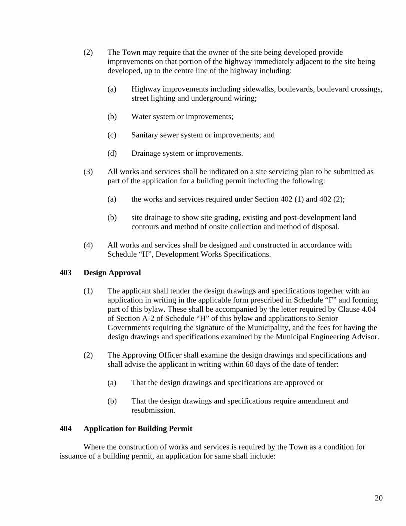
Schedule “B” Town of Port McNeill
Bylaw No. 414 Page 1 of 1
TOWN OF PORT MCNEILL
SECTION 991 DEVELOPMENT SERVICING AGREEMENT
SCHEDULE “B”
------------------------------ (Insert “Subdivision” or “Development”)
CERTIFICATE OF COMPLETION
I hereby certify that the owner has constructed the works and services shown on the following design drawings approved by the Town _______________________________ ____________________________________________________________ (name them) in general conformity with these drawings and the Development Works Specifications of the Town of Port McNeill Subdivision and Development Bylaw No. 414. The “as constructed” drawings of the above works and services are submitted herewith.
Consulting Engineer SEAL Date

28
Schedule “C” Town of Port McNeill
Bylaw No. 414 Page 1 of 1
TOWN OF PORT MCNEILL
SECTION 991 DEVELOPMENT SERVICING AGREEMENT
SCHEDULE “C”
------------------------------ (Insert “Subdivision” or “Development”)
-------------
(Insert “Initial” or “Final”)
CERTIFICATE OF SATISFACTION
I hereby certify that the works shown on the following design drawings have been completed to my satisfaction. Design Drawings: ------------------------------------ (name them) ------------------------------------ ------------------------------------ (For final certificate add: “The warranty obligations of the owner have been satisfied.”)
---------------------------------------- Municipal Engineering Advisor
SEAL
---------------------------------------
Date

29
Schedule “D” Town of Port McNeill
Bylaw No. 414 Page 1
SERVICING LEVELS
The following minimum level of services shall be provided in all subdivisions or developments within the Town of Port McNeill.
(1.) A highway with right-of-way width of 20.00 meters including:
(a) Asphaltic concrete paving on roadways, walkways and lanes. (b) Overhead electric power, telephone and cablevision utilities. Where a new
highway is not created or where the roadway is to be constructed within an existing right-of-way and the existing or adjoining roads have gravel shoulders, the requirement of curb and gutter may be waived.
(2.) A water distribution system in accordance with Schedule “H”, which is connected to
the municipal water system. (3.) A sewage collection system in accordance with Schedule “H”. (4.) A drainage system in accordance with Schedule “H”. (5.) The following servicing requirements may be waived for any new subdivision or
development through the issuance of a Development Variance Permit pursuant to Section 974 of the Municipal Act:
(a) Curb and gutter. (b) Drainage system.

30
Schedule “E” Town of Port McNeill
Bylaw No. 414 Page 1 of 3
APPLICATION FOR PRELIMINARY LAYOUT
APPROVAL FOR SUBDIVISION
Reference Number: __________ Date: _________ ___, 19__ Applicant’ Name: ______________________________________________ Applicant’s Postal Address: ______________________________________ Legal description of property _____________________________________ Street address of property ________________________________________ Type of subdivision: (Check one) [ ] Conventional [ ] Section 996, Municipal Act [ ] Bare Land Strata [ ] Metes and bounds [ ] Other _____________________________________________ (specify) The proposed water supply is: (Check one)
[ ] By Town water system [ ] Wells [ ] Other ______________________________________________ (specify) The proposed method of sewage disposal is: (Check one) [ ] By Town sewer system [ ] By ground disposal I/we hereby apply for Preliminary Layout Approval of a subdivision of the above described property as shown on the attached sketch plan. This subdivision will be in accordance with Bylaw No. 414 and any amendments thereto. The following are submitted as part of this application: 1. Preliminary plan 2. Copy of Certificate of Indefeasible Title 3. Copy of owner’s authorization to applicant (where applicable)
--------------------------------- Signature of Applicant

31
Schedule “E” Town of Port McNeill
Bylaw No. 414 Page 2 of 3
INSTRUCTIONS FOR PREPARATION OF PRELIMINARY PLANS
1. THE PLAN The following should be shown on your preliminary plan: (a) Date it was drawn (b) Scale (c) North Direction (d) Approximate dimensions and area of all proposed parcels, remainders, parks, and rights-of
way. (e) Unique number or letter identifying each lot to be created. (f) Outline of your proposal in red or bold line (g) Legal descriptions of adjacent properties (h) Any existing property lines or roads proposed to be removed (i) Any existing or proposed easements or rights-of-way (j) Existing access roads and other roads or trails on the property (e.g., logging roads, etc) (k) Location and name of all existing and proposed public roads (l) All steep banks or slopes within or adjacent to your proposal that exceed 2 m in height, and
all slopes that are 25% or greater (It may be more practical to provide overall 2 m contours of such areas)
(m) Elevation with grades and/or contour intervals as required above (n) All watercourses within or adjacent to the land to be subdivided, and all proposed drainage
routes (o) Approximate location of all existing and proposed utility services (p) Location of all existing buildings, sources of domestic water, and sewage systems with their
offset distances from the lot lines.
32
Schedule “E” Town of Port McNeill
Bylaw No. 414 Page 3 of 3
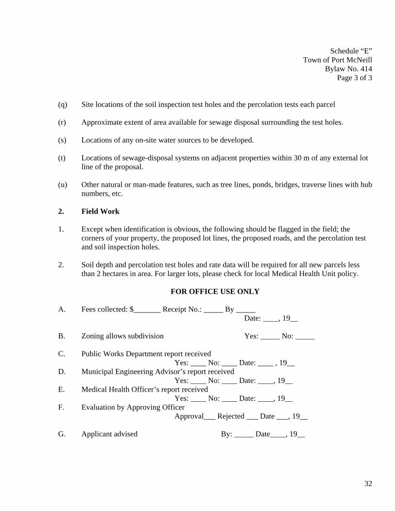
(q) Site locations of the soil inspection test holes and the percolation tests each parcel (r) Approximate extent of area available for sewage disposal surrounding the test holes. (s) Locations of any on-site water sources to be developed. (t) Locations of sewage-disposal systems on adjacent properties within 30 m of any external lot
line of the proposal. (u) Other natural or man-made features, such as tree lines, ponds, bridges, traverse lines with hub
numbers, etc. 2. Field Work 1. Except when identification is obvious, the following should be flagged in the field; the
corners of your property, the proposed lot lines, the proposed roads, and the percolation test and soil inspection holes.
2. Soil depth and percolation test holes and rate data will be required for all new parcels less
than 2 hectares in area. For larger lots, please check for local Medical Health Unit policy.
FOR OFFICE USE ONLY
A. Fees collected: $_______ Receipt No.: _____ By _____ Date: ____, 19__ B. Zoning allows subdivision Yes: _____ No: _____ C. Public Works Department report received Yes: ____ No: ____ Date: ____ , 19__ D. Municipal Engineering Advisor’s report received Yes: ____ No: ____ Date: ____, 19__ E. Medical Health Officer’s report received Yes: ____ No: ____ Date: ____, 19__ F. Evaluation by Approving Officer Approval___ Rejected ___ Date ___, 19__ G. Applicant advised By: _____ Date____, 19__

33
Schedule “F” Town of Port McNeill
Bylaw No. 414 Page 1 of 2
APPLICATION FOR
APPROVAL OF DESIGN DRAWINGS (SUBDIVISION OR DEVELOPMENT)
Reference Number _________________________ Date ____________________________________ Applicant’s Name ____________________________________________________ Applicant’s Address __________________________________________________ Legal Description of Subdivision ________________________________________ Street Location ______________________________________________________ I/we hereby apply for approval of the design drawings (and specifications where applicable) for the above subdivision. The following are submitted as part of this application: 1. 3 paper copies of subdivision plan (for subdivisions only) 2. 3 sets of paper copies of design drawings & specifications. 3. Letter from Consulting Engineer 4. Drain design calculations 5. Senior government permit applications requiring the Town’s signature 6. Fees for Municipal Engineering Advisor studies. ($100.00 plus $100.00 per lot)
____________________________ Signature of Applicant
34
Schedule “F” Town of Port McNeill
Bylaw No. 414 Page 2 of 2
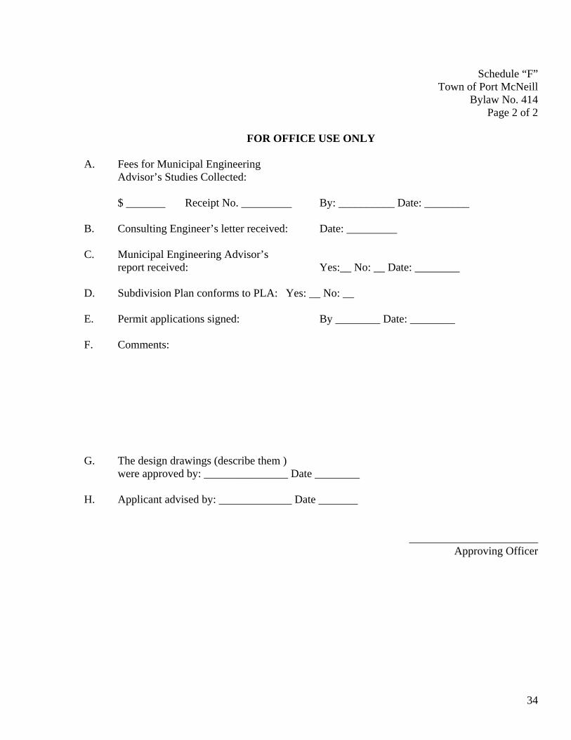
FOR OFFICE USE ONLY
A. Fees for Municipal Engineering Advisor’s Studies Collected: $ _______ Receipt No. _________ By: __________ Date: ________ B. Consulting Engineer’s letter received: Date: _________ C. Municipal Engineering Advisor’s report received: Yes:__ No: __ Date: ________ D. Subdivision Plan conforms to PLA: Yes: __ No: __ E. Permit applications signed: By ________ Date: ________ F. Comments: G. The design drawings (describe them ) were approved by: _______________ Date ________ H. Applicant advised by: _____________ Date _______
_______________________ Approving Officer

35
Schedule “G” Town of Port McNeill
Bylaw No. 414 Page 1 of 2
APPLICATION FOR FINAL APPROVAL OF
SUBDIVISION PLAN
Reference Number: ____________________ Date: ______________, 19___ Applicant’s Name: ______________________________________ Applicant’s Address: ____________________________________ Legal description of Subdivision ___________________________ Street Address of Subdivision: _____________________________ I/we hereby apply for final approval of the above subdivision. The following are submitted as part of this application: 1. Approval fee ($250.00 plus $250.00 per lot) $_____ 2. Development cost charges in the amount of: $_____ 3. Payment Submitted herewith for construction work to be done by the town: $_____ 4. Payment submitted herewith for Town’s costs of connecting up utilities: $_____ 5. Certificate from the Town that all current taxes have been paid. 6. Plan of subdivision. 7. Three paper copies of plan of subdivision. 8. Three sets of paper copies and one film copy of as-constructed drawings. 9. Warranty agreement. 10. Warranty security. 11. Consulting Engineer’s certificate of completion. 12. Municipal Engineering Advisor’s Initial Certificate of Satisfaction. 13. The total cost of construction of the works, inclusive of the Consulting Engineer’s fees is certified to be: $_____ 14. Copy of lawyer’s undertaking to register plans and SRW agreement. 15. Copy of Construction certificate issued under Health Act. 16. Copy of Highways permit. 17. Copies of all other senior government certificates, permits, instructions and comments.
__________________ Signature of Applicant
36
Schedule “G” To Town of Port McNeill
Bylaw No. 414 Page 2 of 2
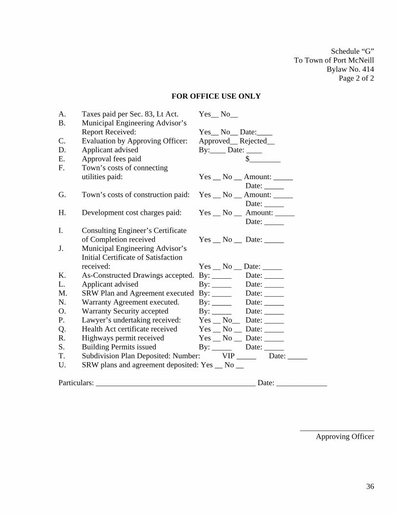
FOR OFFICE USE ONLY
A. Taxes paid per Sec. 83, Lt Act. Yes__ No__ B. Municipal Engineering Advisor’s Report Received: Yes__ No__ Date:____ C. Evaluation by Approving Officer: Approved__ Rejected__ D. Applicant advised By:____ Date: ____ E. Approval fees paid $________ F. Town’s costs of connecting utilities paid: Yes __ No __ Amount: _____ Date: _____ G. Town’s costs of construction paid: Yes __ No __ Amount: _____ Date: _____ H. Development cost charges paid: Yes __ No __ Amount: _____ Date: _____ I. Consulting Engineer’s Certificate of Completion received Yes __ No __ Date: _____ J. Municipal Engineering Advisor’s Initial Certificate of Satisfaction received: Yes __ No __ Date: _____ K. As-Constructed Drawings accepted. By: _____ Date: _____ L. Applicant advised By: _____ Date: _____ M. SRW Plan and Agreement executed By: _____ Date: _____ N. Warranty Agreement executed. By: _____ Date: _____ O. Warranty Security accepted By: _____ Date: _____ P. Lawyer’s undertaking received: Yes __ No__ Date: _____ Q. Health Act certificate received Yes __ No __ Date: _____ R. Highways permit received Yes __ No __ Date: _____ S. Building Permits issued By: _____ Date: _____ T. Subdivision Plan Deposited: Number: VIP _____ Date: _____ U. SRW plans and agreement deposited: Yes __ No __ Particulars: _________________________________________ Date: _____________
___________________ Approving Officer

37
TOWN OF PORT MCNEILL
DEVELOPMENT WORKS SPECIFICATIONS SCHEDULE “H” BYLAW NO. 414

38
Schedule H Town of Development Works Specifications Section A-1 Port McNeill General Introduction Page 1
1.0 Scope
1.01 These specifications shall apply to the design and installation of development works within the Town of Port McNeill. They apply to the design and installation of sewers, drains, waterworks, roads and street lighting together with their respective service connections and appurtenances, and any other works which are required to serve developments.
1.02 The Standard Drawings shall form an integral part of these specifications. 1.03 These specifications do not cover the design of installation of ornamental lighting,
electric power, telephone or television services, but include the preparation of design and as-constructed drawings for these works.
2.0 General 2.01 The following specifications shall apply to all works: Section A-1 General Introduction A-2 Development Procedures and Policies B-1 Preparation of Design Drawings B-2 Preparation of As-Constructed Drawings SD-1 Design of Sewers and Drains SD-2 Installation of Sewers and Drains W-1 Design of Waterworks W-2 Installation of Waterworks T-1 Trenching, Excavating and Backfilling R-1 Design of Roads R-2 Construction of Roads Appendices 1 to 8 inclusive Standard Drawings

39
Schedule H Town of Development Works Specifications Section A-2 Port McNeill Development Procedure and Policies Page 1
1.0 Introduction
1.0 This section described the development procedures and policies of the Town of Port McNeill.
2.0 General Information
2.01 The entire cost of design and construction of all works required to serve developments shall be at the expense of the Developer.
2.02 Preparation of all contract drawings and documents shall be carried out by the
Consulting Engineer retained by the Developer. 2.03 No building permits shall be issued in relation to any development until:
- The subdivision plan (if any) is deposited. - The water, sewer and drain works and a road capable of supporting
emergency and service vehicles have been installed and recommended for acceptance by the Consulting Engineer.
- The as-constructed drawings for the water, sewer, drain and road works have been delivered to and accepted by the Municipality.
2.04 All works shall be designed and installed as detailed in these specifications and in
accordance with the procedure set out herein. 2.05 Where strict compliance with these specifications is impractical or unreasonable, the
Municipality may permit a minor deviations shall be included in the Consulting Engineer’s as-constructed drawings.
3.0 Statutory Rights-of-way and Easements
3.01 All works constructed by the Developer which lie outside of highways ad defined in the Land Title Act shall be within Statutory Rights of way or easements.
3.02 The costs of having the appropriate Statutory Right-of-Way plans and agreements,
and easement plans and agreements, and registration of same, shall be borne by the Developer.
3.03 Statutory Right-of-Way [plans and agreements shall be submitted by the Owner to the
Municipality for execution. Following execution, the Municipality shall release such documents to the Owner’s solicitor on his undertaking to register same.

40
3.04 Right-of-way documents for electric power, telephone and cablevision facilities shall
be prepared and registered by the respective utility companies. 3.05 Where a single sewer, drain or water right-of-way is required, the minimum
acceptable width is 3.1 meters. 3.06 Where more than one sewer, drain or water pipe is installed in a right-of-way, the
width of the right-of-way must be increased sufficiently to accommodate the pipes required together with no less than 1.2 meters of clearance between the pipes and the right-of-way limit. The minimum acceptable width in this case is 3.7 meters.
3.07 Rights-of-way shall be located within a single property adjacent and parallel to
adjacent property boundaries and shall not encumber proposed building sites. 3.08 Rights-of-way shall be provided by the Owner for the future extension of the sewer or
drain as required by the Municipal Engineering Advisor. 3.09 Copies of all Statutory Right-of-way plans and agreements, and all easement plans
and agreements, showing the particulars of registration in the Land Title Office, shall be submitted by the Owner to the Municipality immediately following registration.
4.0 Responsibilities of Consulting Engineer
4.01 The Consulting Engineer shall be appointed and paid by the Owner and shall render his services pursuant to a contract with the Owner.
4.02 The Consulting Engineer shall be responsible for the design of the works, approval of
material used, layout of the works upon the ground, field observation of construction, field measurements of works constructed and the preparation of as-constructed drawing.
4.03 Field observation of construction shall consist of applying such selective sampling
procedures at the site as the Consulting Engineer, in his sole professional discretion considers necessary to enable him to ascertain whether the contractor is constructing the works in general conformity with the design drawings for the project and this specification. When requested, the Consulting Engineer shall submit copies of his reports of field observations to the Municipality.
4.04 The Consulting Engineer shall submit to the Municipality a letter confirming that he has entered into a contract with the Owner which authorizes him to provide the level of professional engineering services required by Clauses 4.02 and 4.03 above.
Schedule H Town of Development Works Specifications Section A-2 Port McNeill Development Procedure and Policies Page 2

41
4.05 The Consulting Engineer shall notify the municipality in writing as soon as possible if
his contract is terminated at any time prior to the completion and acceptance of works for which he has prepared design drawings.
4.06 The design drawings shall conform to all the Preliminary Layout Approval, this
specification, all applicable by-laws of the Municipality and all acts of senior governments.
4.07 If the Consulting Engineer wishes to make any changes in approved design drawings
following the approval by the Municipality, he shall submit the changed design drawings to the Municipality in the same manner as the original design drawings.
4.08 In addition to the field observations by the Consulting Engineer, representatives of
the Municipality may periodically inspect the works. They shall bring to the attention of the Consulting Engineer the use of unacceptable materials or the performance of unacceptable work or other objections. If remedial action is not taken to the satisfaction of the approving Officer, the Engineer that construction is to cease until remedial action is taken.
5.0 Approval of Design Drawings
5.01 Three sets of paper prints of the design drawings shall be submitted to the Municipality, together with the application in Schedule “C”.
5.02 After review of the drawings, the Consulting Engineer will be advised if they are
acceptable, or if amendments are required. 5.03 When any requested amendments have been made, the Consulting Engineer shall
resubmit two sets of paper prints of drawings as amended. 5.04 Upon it being satisfied with the design drawings and specifications, the Municipality
shall issue an approval in the form of Schedule “C”. 5.05 No construction of the works shall be commenced before the design drawings have
been approved. A copy of these specifications and the approved Design Drawings shall be retained by the Contractor at the site during construction of the works.
5.06 No sewer, drain or water main within a development shall be permitted to operate as
part of the related Municipal systems until the works have been accepted by the Municipality.
Schedule H Town of Development Works Specifications Section A-2 Port McNeill Development Procedure and Policies Page 3

42
6.0 Approval by Senior Governments
6.01 Where permits or authorizations are required from senior governments, the Applicant shall apply for these Developments adjacent to, affected by, or affecting the following, will require the appropriate applications to the appropriate senior government agency.
Ministry of Transportation and Highways (Access and Construction Permits) Ministry of Health (Waterworks Construction Permits) Ministry of Environment (Waterworks Approvals) Navigable Water Protection Act (Permits for Work in Navigable Waters) Canada Post (Super Mail Box Locations) The appropriate applications shall be prepared by the Applicant and submitted to the
Municipality for signature prior to submission to the senior government agency. Copies of all permits and approvals issued by those agencies shall be forwarded by the Owner to the Municipality.
7.0 Warranty of Construction
7.01 Pursuant to Section 2.06 of the Subdivision and Development By-law, the Owner shall enter into an agreement in the form Schedule “G”.
7.02 The Owner shall be responsible for and at his own expense execute all work, repair,
alteration, reconstruction or replacement required to remedy any defect, fault or deficiency in or developing in the completed work not only up to the receipt and acceptance of the Consulting Engineer’s as-constructed drawings but also during the period of warranty of twelve months after the date of acceptance of the as-constructed drawings..
7.03 The Owner shall guarantee the workmanship and the performance of the required
work by the submission to the Municipality of a certified check or an Irrevocable Letter of Credit for five percent of the total cost of construction of the works as certified by the Owner in the form in Schedule “D” to the Subdivision and Development By-law, or five hundred dollars, whichever is greater.
7.04 All such work of rectification, repair and warranty shall be executed upon the written
request of the Municipality. Should the Owner neglect or fail to commence execution of such work within the time set by the Municipality, the Municipality shall complete the remedial work according to the terms of the Warranty
Schedule H Town of Development Works Specifications Section A-2 Port McNeill Development Procedure and Policies Page 4

43
Agreement. The Municipality shall cash the security deposit and deduct its costs of performing the required work from the proceeds thereof.
7.05 If no defects or deficiencies have developed during the period of warranty, the
security deposit shall be returned to the owner.
8.0 Approval of As-Constructed Drawings
8.01 Upon it being satisfied with the as-constructed drawings, the Municipality shall issue an approval in the form of Schedule “D”.
9.0 On-Site Sewage Disposal
When on-site sewage effluent disposal is permitted, the design and installation of such system shall be in compliance with the regulations of the Ministry of Health, the Upper Island Health Unit, or the Ministry of Environment depending on the required capacity of the proposed system and a certificate approval or other proof of compliance obtained from the relevant authority.
Schedule H Town of Development Works Specifications Section A-2 Port McNeill Development Procedure and Policies Page 5

44
Schedule H
Town of Development Works Specifications Section B-1Port McNeill Design Drawings Page 1
1.0 Scope
1.01 This specification shall govern the preparation of all engineering drawings for design of services within the Municipality.
2.0 General
2.01 Any information received from the Municipality on existing services shall be used as a general guide only. Locations and elevations must be checked by actual survey. The Municipality assumes no responsibility for the exactness of works information obtained from municipal drawings. Underground locations shall be confirmed with utility companies.
2.02 Vertical control shall be shown in metric to the Port McNeill datu. Bench mark
numbers, locations and elevations can be obtained from the Municipality. The reference bench mark and elevation shall be shown on the design drawing.
2.03 Show the elevation of all; iron survey posts, existing basement floors and, where the
building site is less than 1 m above the road level, any proposed basement floor elevation. This information and connection information may be in pencil at the design stage but shall be in ink for as-built drawing submission. For subdivisions, indicate by shading the potential building envelope and, where land is below the calculated minimum floor elevation, show elevations at corners of the envelope or show a centre of lot profile to determine the amount of fill required for building.
2.04 All existing statutory rights-of-way or easements and their permitted uses must be
checked through the Land Title Office and be shown lightly shaded on the design drawing. Registration and plan numbers shall be shown.
2.05 All proposed rights-of-way for new works are to be shown as a dashed line. Theses
shall be tied to the iron pin in each lot, together with their width, permitted use, and the note “to be acquired” or “proposed”. Statutory Right-of-way documents shall be prepared as detailed in these specifications.
2.06 A north arrow, existing and proposed street names shall be shown on the design
drawing. The north shall be generally oriented towards the top of the sheet. 2.07 All works shall generally be shown on one plan with curbs (mountable or non-
mountable), sidewalks, sewers, drains, gas, water, and underground wiring and poles identified as MC or NMC, S/W, S, D, G, W and U/G, H or T respectively. Other services shall be clearly designated on the drawing.

45
2.08 Existing water mains, sanitary sewer mains, storm drains (including all
appurtenances), ditches, pavement, curbs, sidewalks, underground wiring, gas, poles, trees, service connections and other underground utilities shall be indicated in plan and profile where applicable.
2.09 All proposed works shall be fully dimensioned as specified.
3.0 Drawing Information
3.01 Standard sheet size is A1 metric size is 594 mm x 841 mm. 3.02 Use transparent plan/profile paper. Personalized company plan/ profile paper may be
used provided it meets the following requirements:
1) Plan view shall be in the lower half of the page. 2) Profile view shall be 1 x 5 lines to the centimetre and occupy the upper half of
the page. The use of plan on one sheet and profile on a second sheet shall not be
allowed.
3.03 Dimensioning of the drawing shall be given from an existing or proposed iron pin or lot line.
3.04 Proposed construction shall be shown as solid lines and the existing shown as dashed
lines. 3.05 Lines printing shall be of uniform size using the following weights for: Lot lines #.25;
Road lines #.5; sewer, drain, water lines #.35. Construction notes shall be confined to a separate “note” column, wherever possible, with numbered references in plan or profile.
3.06 Road Chainage shall be tied to an iron survey post at the start of construction.
4.0 Scales
Normality: Horizontal 1:500 Vertical 1:100 or 1:50 Details: Horizontal 1:200 Vertical 1:20 or 1:50 Cross Sections: Horizontal 1:000 Vertical 1:100 Structural Details 1:20 * e.g.: a detail of piping around two closely spaced manholes
Schedule H Town of Development Works Specifications Section B-1 Port McNeill Design Drawings Page 2

46
5.0 Requirements for Subdivision Key Plan
5.01 A key plan, shall be included on the right side of the design drawing and shall include the following information:
a) Plan of adjacent streets and existing lots with streets named and legal
description of adjacent lots given: b) Civic address with the property being subdivided shown shaded; c) North arrow; d) The location of existing and proposed hydrants: e) Title: “Proposed Subdivision of (give full legal description”; f) If the subdivision is to be developed in stages, each proposed stage shall be
clearly outlined and order of development indicated.
6.0 Requirements for Roads or Parking Areas.
6.01 Show all iron posts adjacent to the works and the existing ground elevation at each post or proposed post.
6.02 Both plan and profile shall be tied to an iron post, preferably near or at 0 +) chainage.
If the chainage exceeds 120 m, a second tie shall be shown. 6.03 Show the road width, curb and sidewalk offsets measured from the property line. 6.04 Road profiles shall show gutter elevations, except centre line profiles will be used
where thee are no curbs. 6.05 Detail the road construction with a cross sectional view of construction when
circumstances require special consideration. In all cases the standard drawing section shall be referenced on the drawing.
6.06 The profile shall be shown at true centerline length and provided in as close
relationship as possible to the plan. 6.07 Locate catch basins. 6.08 Locate barricades.
Schedule H Town of Development Works Specifications Section B-1 Port McNeill Design Drawings Page 3

47
6.09 Locate ditches and centre of pavement in minimum road construction by offsetting to
property line. 6.10 Existing and proposed critical driveway locations within the subdivision shall be
shown as well as a profile of each driveway from the road centerline to the end of the driveway within the property.
6.11 Chainage of the BC and EC of horizontal curves shall be shown together with the
internal angle, tangent length, arc and centerline radius. Curb radii shall be shown. 6.12 The percent grade to two decimal places shall be shown on the profile together with
the following information on vertical curves:
a) The chainage and elevations of BVC, EVC, and VPI; b) The value, the external, e; c) The length of vertical curve; d) The elevation and chainage of the low spot of sag curves.
6.13 On superelevated curves and cul-de-sacs on vertical and horizontal curves, show a gutter profile (no centerline profile).
7.0 Requirements for Sewer and Drain
7.01 The following information shall be shown on the profile:
a) Size, type, class of pipe, class of bedding: b) Percent grades to two decimal places. If critical, mark “CR” after the grade, if
not critical, show the minimum grade thus: (1.08% min.); c) Invert elevations at both inlet and outlet of manholes; d) Information on vertical curves as detailed in paragraph 6.12); e) Existing utilities.
7.02 The following information shall be shown on the plan;
a) Information on horizontal curves as detailed in paragraph 6.11;
Schedule H Town of Development Works Specifications Section B-1 Port McNeill Design Drawings Page 4
48
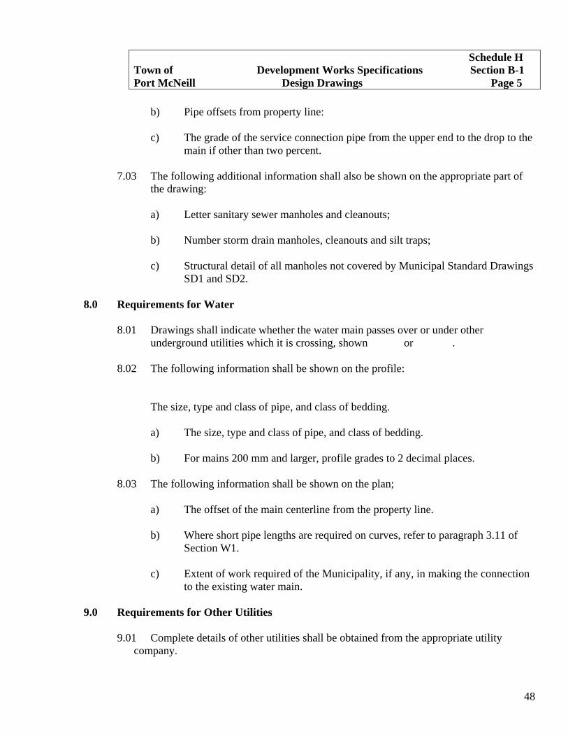
b) Pipe offsets from property line: c) The grade of the service connection pipe from the upper end to the drop to the
main if other than two percent.
7.03 The following additional information shall also be shown on the appropriate part of the drawing:
a) Letter sanitary sewer manholes and cleanouts; b) Number storm drain manholes, cleanouts and silt traps; c) Structural detail of all manholes not covered by Municipal Standard Drawings
SD1 and SD2.
8.0 Requirements for Water
8.01 Drawings shall indicate whether the water main passes over or under other underground utilities which it is crossing, shown or .
8.02 The following information shall be shown on the profile:
The size, type and class of pipe, and class of bedding. a) The size, type and class of pipe, and class of bedding. b) For mains 200 mm and larger, profile grades to 2 decimal places.
8.03 The following information shall be shown on the plan; a) The offset of the main centerline from the property line. b) Where short pipe lengths are required on curves, refer to paragraph 3.11 of
Section W1. c) Extent of work required of the Municipality, if any, in making the connection
to the existing water main.
9.0 Requirements for Other Utilities
9.01 Complete details of other utilities shall be obtained from the appropriate utility company.
Schedule H Town of Development Works Specifications Section B-1 Port McNeill Design Drawings Page 5

49
9.02 The following information shall be shown on the plan:
a) Existing utilities. b) Utility offset from property line and/or iron pin. c) Lot connections and other appurtenances. d) Existing and proposed poles shall be dimensioned from the pole road face to
property line and/or survey post.
9.03 Underground hydro, telephone and gas shall be shown schematically.
10.0 Requirements for Street Lighting
10.01 The following information shall be shown on the plan:
a) Location of existing luninaries. b) Location, type and wattage or proposed luminaires. c) Line diagram and junction boxes.
Schedule H Town of Development Works Specifications Section B-1 Port McNeill Design Drawings Page 6

50
Schedule H Town of Development Works Specifications Section B-2 Port McNeill As Constructed Drawings Page 1
1.0 Scope
1.01 This specification shall govern as-constructed drawings of the following services; drains, sewers, water, roads, curbs, lighting, side-walks, overhead power, telephone and cablevision, culverts, bridges, and other miscellaneous permanent structures.
2.0 General
2.01 As-constructed drawings shall consist of one mylar copy of the approved design drawing with changes or corrections made as required in Section 2.02.
2.02 The as-constructed drawings shall clearly show the location of all services as installed
using offsets from survey posts. The locations will be shown with the current dimensions. In addition, the location to the end of underground pipe shall be shown.
2.03 For each run of pipeline, the Engineer shall assign a station 0+000 to some surface
box or other component and shall give the chainage for each component or fitting along the axis of the pipe from the assigned station 0+000 to the end of that run.
2.04 Within two weeks of completion of water and within four weeks of completion of all
other services to be installed by the Applicant, the Consulting Engineer shall deliver “as-constructed” drawings to the Municipal Engineering Advisor. These drawings shall be in the form of mylar copies and shall include the following statement signed, sealed and dated by the Consulting Engineer:
“I certify that the following services (name them) were inspected during
construction and to the best of my knowledge, were installed in general conformity with the Municipal Development works Specifications and Standard Drawings and as shown on this drawing.”
3.0 Tolerances
3.01 a) All horizontal dimensions shall be to the nearest 150 mm;
b) All vertical elevations to the nearest 3 mm except that ground elevations and service connection inverts at property line shall be to the nearest 30 mm;
c) Road horizontal locations shall be to the nearest 30, mm; d) Road vertical locations shall be to the nearest 15 mm. e)

51
4.0 Additional Required Details
4.01 Drain and sewer
a) Location of rock cuts and hardpan requiring blasting, and depth of rock excavation;
b) The invert elevation at both inlet and outlet of manholes: c) Tie locations of manholes, cleanouts and other appurtenances to survey posts. d) Locate catch basin leads at the main by measurement from the center of the
downstream manhole: e) Locate service connections at property line showing distance from the nearest
survey post and at the main by chainage from the centre of the downstream manhole.
f) Show ground and invert elevations of sewer and drain service connections at
the property line or edge of right-of-way.
4.02 Water
a) Show water service and tie to corner survey post; b) Location of rock cuts and maximum depth of rock excavation; c) Profile of main indicating numerically the invert at 15 m stations; d) Tie locations of fire hydrants to main valve and survey post; e) Locate all valves and tie to iron poles.
4.03 Road, Curb and Sidewalk
a) Location and dimensions of service connections and all surface appurtenances, tied to survey posts.
Schedule H Town of Development Works Specifications Section B-2 Port McNeill As Constructed Drawings Page 2

52
4.04 Underground Power, Telephone and Cablevision
a) Location and dimensions of service connections and all surface appurtenances, tied to survey posts.
4.05 Bridges, Etc.
a) Location of structure; b) Elevation of deck.
4.06 Lighting and Traffic Control
a) Location of luminaires tied to a survey post. b) Line diagram; c) Connection points to B.C. Hydro and photo electric controllers.
Schedule H Town of Development Works Specifications Section B-2 Port McNeill As Constructed Drawings Page 3

53
Schedule H Town of Development Works Specifications Section SD-1
Port McNeill Design of Sewers and Drains Page 1
1.0 Scope
1.01 This specification shall govern the design of all sewers and drain pipes and their appurtenances within the Municipality.
2.0 General
2.01 The Municipality reserves the right to make all connections or alterations to existing sewer and drain systems at the expense of the Applicant where it can be demonstrated that such works are necessary to accommodate the Applicant’s development.
2.02 Upstream sewerage areas and other criteria required to accommodate upstream
sewerage is normally specified by the Municipality. 2.03 Sewer design shall conform with the current “Guidelines for Assessing Sewerage
Works” as prepared by the Ministry of the Environment of the Province of British Columbia.
2.04 In area subject to excessive overland flows, or in seepage areas, french drains,
diversion ditches, catch basins, etc. as required shall be installed and connected to acceptable outlets.
2.05 Only one single catch basin shall be connected to each 150 mm lead. 2.06 Catch basins shall be located in accordance with Regional Specification R-1 and
installed in accordance with Regional Specifications R-2. 2.07 Discharges from commercial garages shall be intercepted by combination silt
trap/grease interceptors prior to entering the Municipal storm drain system. 2.08 Open ditches shall enter an enclosed storm drain system through a silt trap. 2.09 Driveway culverts shall be a minimum 300 mm diameter and 6.0 m in length.
3.0 Drainage Design Criteria: Runoff Prediction
3.01 Upstream drainage areas and other criteria required to accommodate upstream drainage will be specified by the Municipal Engineering Advisor upon application from the Consulting Engineer.

54
3.02 It shall be the responsibility of the Consulting Engineer to summarize drainage
computations pertaining to that project and submit this data to the Municipality for approval together with a contour plan (scale 1:2500 where available) showing the drainage boundaries.
3.03 Subject to the approval of the Municipality, the principles of stormwater management
– “zero increase in runoff” may be incorporated into the design of storm drains. 3.04 The recurrence interval used in designing storm drains up to and including 900 mm
shall be ten years. Drains greater than 900 mm shall be designed to 25 years. 3.05 The intensity-duration curve to be used will be that included in these specifications. 3.06 Drain pipes shall be designed according to the following version of Rational Formula,
Q=1.3AIR where Q=flow in cfs, Area = tributary area in acres, R = the coefficient of runoff from clause 3.07 below.
3.07 The following minimum values shall be used for the inlet time to the upstream end of
nonextendable storm drain lines and for the coefficient of runoff (R)
a) Unimproved areas, parks, playgrounds, cemeteries, etc – inlet time to be determined using standard engineering practice and R = 0.35.
b) Residential areas – low density, single family dwelling neighbourhoods – inlet
time = 10 minutes and R = 0.60. c) High density and largely impervious areas – inlet time = 5.0 minutes and 0.90
<R <1.0.
The above standards are minimum values only. Composite values based on percentages of different types of contributory areas may be established from the above figures. Future land use, as detailed in the Community Plan, shall be incorporated in the design.
4.0 Sewer and Drain Design Criteria: Pipe Capacity
4.01 Pipes shall be designed to carry the required design flow when flowing full except for pipes carrying flows less than that required for the minimum pipe size.
Schedule H Town of Development Works Specifications Section SD-1
Port McNeill Design of Sewers and Drains Page 2
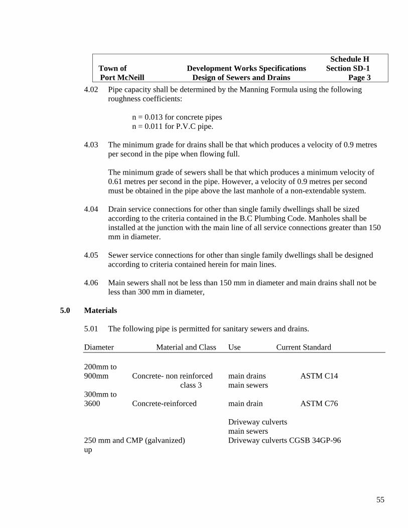
55
4.02 Pipe capacity shall be determined by the Manning Formula using the following
roughness coefficients: n = 0.013 for concrete pipes n = 0.011 for P.V.C pipe. 4.03 The minimum grade for drains shall be that which produces a velocity of 0.9 metres
per second in the pipe when flowing full. The minimum grade of sewers shall be that which produces a minimum velocity of
0.61 metres per second in the pipe. However, a velocity of 0.9 metres per second must be obtained in the pipe above the last manhole of a non-extendable system.
4.04 Drain service connections for other than single family dwellings shall be sized
according to the criteria contained in the B.C Plumbing Code. Manholes shall be installed at the junction with the main line of all service connections greater than 150 mm in diameter.
4.05 Sewer service connections for other than single family dwellings shall be designed
according to criteria contained herein for main lines. 4.06 Main sewers shall not be less than 150 mm in diameter and main drains shall not be
less than 300 mm in diameter,
5.0 Materials
5.01 The following pipe is permitted for sanitary sewers and drains. Diameter Material and Class Use Current Standard 200mm to 900mm Concrete- non reinforced main drains ASTM C14 class 3 main sewers 300mm to 3600 Concrete-reinforced main drain ASTM C76 Driveway culverts main sewers 250 mm and CMP (galvanized) Driveway culverts CGSB 34GP-96 up
Schedule H Town of Development Works Specifications Section SD-1
Port McNeill Design of Sewers and Drains Page 3

56
150mm to 400 mm Ductile Iron – 1035 kPa for main AWWA C151-76 drains or catch basin leads main sewer 100mm and 150mm PVC Gravity Sewer Pipe 100mm and 150mm CSA B182.1 DR 28, pipe stiffness of for service ASTM D2412-73 not less than 690 KPa with connections rubber gasket and integral 150mm for catch bell. leads 200mm to 375mm PVC Gravity Sewer Pipe main drains ASTM D3034 DR 35, pipe stiffness of 200mm for double CSA B182.2 not less than 320 KPa with catch basin ASTM D2412-73 rubber gasket and integral leads main sewers 200mm to 1200mm Ribbed PVC gravity sewer main drains CSA B182.4 pipe with rubber gasket, ASTM F-794 pipe stiffness of not less UNI-B-9-82 than 320 KPa
6.0 Field Support Strength
6.01 The class and type of pipe and fittings, together with required class of bedding and trench widths shall be so selected that the pipe will support the anticipated gravity earth and any surface dead and live loads with a safety factor 1.5.
6.02 Minimum cover for PVC pipe shall be 750mm. For installations under areas used for
vehicular traffic, minimum cover shall be 1.0 m. Minimum cover for rigid pipe shall be 500 m. For installations under areas used for vehicular traffic, minimum cover shall be 1.0 m., except for catch basin leads.
7.0 Alignment and Grade
7.01 Pipe lines shall normally be designed to follow a straight alignment and constant grade between manholes.
7.02 a) Curves will normally only be acceptable when a straight alignment and Constant grade between manholes is not feasible.
Schedule H Town of Development Works Specifications Section SD-1
Port McNeill Design of Sewers and Drains Page 4
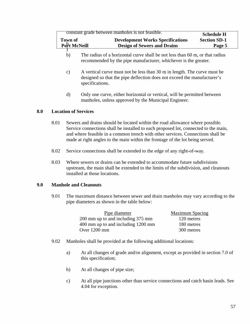
57
constant grade between manholes is not feasible.
b)b) The radius of a horizontal curve shall be not less than 60 m, or that radius
recommended by the pipe manufacturer, whichever is the greater.
c) A vertical curve must not be less than 30 m in length. The curve must be designed so that the pipe deflection does not exceed the manufacturer’s specifications. d) Only one curve, either horizontal or vertical, will be permitted between manholes, unless approved by the Municipal Engineer.
8.0 Location of Services
8.01 Sewers and drains should be located within the road allowance where possible. Service connections shall be installed to each proposed lot, connected to the main, and where feasible in a common trench with other services. Connections shall be made at right angles to the main within the frontage of the lot being served.
8.02 Service connections shall be extended to the edge of any right-of-way. 8.03 Where sewers or drains can be extended to accommodate future subdivisions
upstream, the main shall be extended to the limits of the subdivision, and cleanouts installed at those locations.
9.0 Manhole and Cleanouts
9.01 The maximum distance between sewer and drain manholes may vary according to the pipe diameters as shown in the table below:
Pipe diameter Maximum Spacing
200 mm up to and including 375 mm 120 metres 400 mm up to and including 1200 mm 180 metres Over 1200 mm 300 metres
9.02 Manholes shall be provided at the following additional locations:
a) At all changes of grade and/or alignment, except as provided in section 7.0 of this specification;
b) At all changes of pipe size; c) At all pipe junctions other than service connections and catch basin leads. See
4.04 for exception.
Schedule H Town of Development Works Specifications Section SD-1
Port McNeill Design of Sewers and Drains Page 5

58
d) Where service connection is the same size as the main.
9.03 Drop manholes will be allowed only where particular circumstances preclude the use of normal manholes. These shall be constructed wherever the change in invert elevations through the manhole is greater than 600 mm.
Allowance shall be made in the design for the effect of the resulting turbulence on the
hydraulic capacity of the system. 9.04 The relative elevations entering and leaving a manhole are to be such as to ensure that
the manhole does not reduce the hydraulic capacity of the system.
a) Allowances for energy losses or changes in velocity are to be determined in accordance with sound hydraulic principles.
b) Junctions will require special treatment as will all situations involving a pipe
flowing into a smaller pipe at a steeper grade.
9.05 All manholes with pipes 450 mm or larger shall be individually designed. 9.06 Stubs shall be placed in manholes to allow for future connections. The length of the
stubs shall be 600 mm maximum from the outside of the manhole. The end shall be securely capped.
9.07 Cleanouts shall be installed at the upstream end of all sewer and storm drain lines.
Schedule H Town of Development Works Specifications Section SD-1
Port McNeill Design of Sewers and Drains Page 6

59
Schedule H Town of Development Works Specifications Section SD-2 Port McNeill Installation of Sewers and Drains Page 1
1.0 Scope
1.01 This specification shall govern the installation of all sewer and drain pipes and their appurtenances within the Municipality.
2.0 General
2.01 Provision shall be made to maintain the flow of all drains, ditches, watercourses, and service connections which may be encountered with during the progress of the work. Where substandard systems are anticipated or located during construction, the substandard system shall be connected to the new installation or replaced. In every case the contractor or Consulting Engineer shall notify the Municipality when substandard systems are found. The contents of any sewer, drain or service connection shall not be allowed to flow into the trench or into the main. All offensive matter shall be immediately removed from the proximity of the work.
2.02 The Contractor shall ensure debris and mortar droppings do not enter any part of the
sewer or drain system and shall leave all pipe lines, manholes, cleanouts, silt traps, catchbasins, and other appurtenances in a thoroughly clean condition.
3.0 Bedding
3.01 The class of bedding shall be as indicated on the approved design drawing. 3.02 All small diameter non-rigid (PVC) pipe to be provided with minimum Class B
bedding compacted to 95% Standard Proctor Density. 3.03 All non-rigid (PVC) catch basin leads must be bedded according to the latest ASTM
D 2321 Class II or better, compacted to 95%. Standard Proctor Density. 3.04 Ribbed PVC pipe must be bedded in accordance with the latest ASTM D2321, Class
II or better.
4.0 Installation 4.01 Pipes shall be handled, stored and laid in accordance with the recommendations of the pipe
manufacturer. In all cases gaskets shall be installed unless otherwise specified by the Municipal Engineering Advisor.
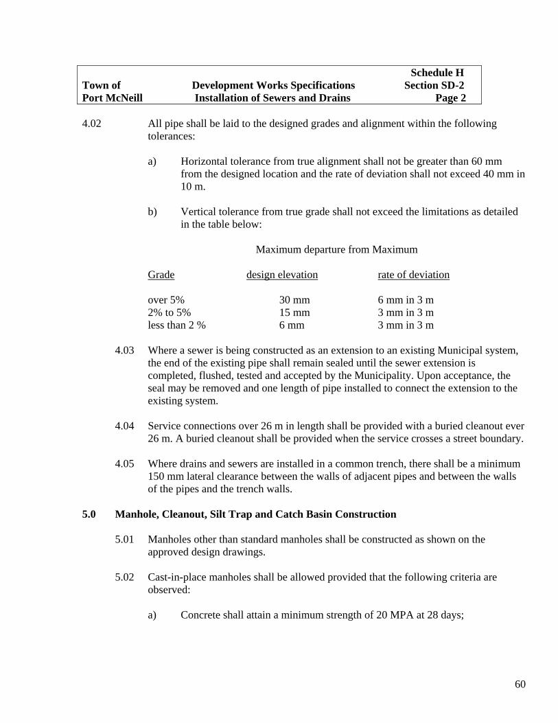
60
Schedule H Town of Development Works Specifications Section SD-2 Port McNeill Installation of Sewers and Drains Page 2 4.02 All pipe shall be laid to the designed grades and alignment within the following
tolerances:
a) Horizontal tolerance from true alignment shall not be greater than 60 mm from the designed location and the rate of deviation shall not exceed 40 mm in 10 m.
b) Vertical tolerance from true grade shall not exceed the limitations as detailed
in the table below:
Maximum departure from Maximum
Grade design elevation rate of deviation over 5% 30 mm 6 mm in 3 m 2% to 5% 15 mm 3 mm in 3 m less than 2 % 6 mm 3 mm in 3 m
4.03 Where a sewer is being constructed as an extension to an existing Municipal system, the end of the existing pipe shall remain sealed until the sewer extension is completed, flushed, tested and accepted by the Municipality. Upon acceptance, the seal may be removed and one length of pipe installed to connect the extension to the existing system.
4.04 Service connections over 26 m in length shall be provided with a buried cleanout ever
26 m. A buried cleanout shall be provided when the service crosses a street boundary. 4.05 Where drains and sewers are installed in a common trench, there shall be a minimum
150 mm lateral clearance between the walls of adjacent pipes and between the walls of the pipes and the trench walls.
5.0 Manhole, Cleanout, Silt Trap and Catch Basin Construction
5.01 Manholes other than standard manholes shall be constructed as shown on the approved design drawings.
5.02 Cast-in-place manholes shall be allowed provided that the following criteria are
observed:
a) Concrete shall attain a minimum strength of 20 MPA at 28 days;

61
Schedule H Town of Development Works Specifications Section SD-2 Port McNeill Installation of Sewers and Drains Page 3
b) Minimum wall thickness shall be 150 mm; c) Minimum internal dimensions shall be as detailed on Municipal Standard
Drawings for standard manholes.
5.03 The manhole frames shall sit on at least one course of mortared concrete brick or approved alternate which shall be parged on both sides with a mortar paste composed of one part cement and three parts of sand and only sufficient water for workability.
a) Grade adjustment of this type shall not exceed 250 mm. Bricks laid for
adjustment shall be laid in headers.
5.04 Within the travelled portion of the road, heavy duty 200 mm frames and covers shall be installed on manholes, silt traps and cleanouts.
5.05 Within sewer or drain rights-of-way:
a) Heavy duty 200 mm frames and covers shall be installed on manholes, silt traps and clean outs in travelled areas where it is known at the time of construction.
b) Medium duty 100 mm covers shall be used in non-travelled areas.
5.06 All manholes and cleanouts not within the travelled portion of the road shall be set to finished landscaped elevation or 75 mm above existing grade if landscaped elevation is not available.
5.07 The area around silt trap shall be graded so that surface runoff enters the grilled lid.
The ditch sides and bottom around an inlet or outlet shall be rip-rapped for a minimum length of 1.5 m beyond the end of the pipe.
6.0 Testing
6.01 Sewer pipe other than P.V.C shall be tested at an average internal air pressure of 3.0 pounds per square inch greater than the back pressure of any ground water that may submerge the pipe. Ground water pressure shall be measured at the crown of the pipe at the lower end of the section under test. The maximum rate of air loss shall not be greater than 0.0030 cubic feet of free air per minute per square foot of internal pipe surface.

62
Schedule H Town of Development Works Specifications Section SD-2 Port McNeill Installation of Sewers and Drains Page 4
6.02 The requirement of paragraph 6.01 shall be considered satisfied if the time, in
seconds, required for the pressure to decrease from 3.5 pounds to 2.5 pounds per square inch greater than the back pressure of ground water as measured in paragraph 6.01 is not less than the allowable time calculated as follows:
a) List diameters and lengths of all pipes under test. b) Calculate for K = 0.011d² L where d = diameter of pipe in inches and L =
length in feet of pipe of diameter “d”. c) Calculate a value for C = 0.0003882dL where d = diameter of pipe and L =
length of pipe of diameter “d”. d) Add all up to values of K e) Add up all the values of C. f) If the total off C values is less than one, the total of all K values is the
allowable time in seconds. g) If the total of all C values is great than one, divide the total of all K values by
the total of all C values. The result is the allowable time in seconds.
6.03 Alternate Tests – Sewer
a) Infiltration – The maximum allowable amount of infiltration from ground water or other sources into the section under test shall be 100 gallons per inch of pipe diameter per mile per 24 hours.
b) Exfiltration – The maximum allowable amount of exfiltration from section of
sewer under test shall be a rate not greater than the manufacturer’s specification for the pipe being tested.
c) Modified Air Test – The test length shall be subjected to air pressure equivalent to
a four-inch head of water. Leakage from the pipe shall be considered acceptable if, after disconnecting the air source, the pressure drop in five minutes is not more than one-inch head of water.

63
6.04 Air Test for P.V.C Sewer Pipe The air test shall conform to the procedures outlined in Uni-Bell Plastic Pipe
Association “Handbook for P.V.C Pipe” – Appendix Uni-B-6-79 or subsequent issues and is generally as follows:
The duration permitted for a prescribed low pressure air exfiltration pressure drop
between two consecutive manholes shall be not less than that shown in Table A. The prescribed drop shall not exceed 0.5 psi from 3.5 to 3.0 psi in excess of the ground water pressure above the top of the sewer.
Table A
Minimum Duration for Air Test Pressure Drop
Time Pipe Size Inches mm Minutes 4 100 2 ½ 6 150 4 8 200 5 10 250 6½ 12 300 7½ 15 380 9½ 6.05 It is to be noted that the foregoing calculations are made using Imperial units of
measurement. 6.06 Video Camera inspection, Sewer or Drain. If the Municipal Engineering Advisor has reason to question the quality of the
construction of any sewer or drain prior to acceptance of it, the Consulting Engineer shall arrange for a video camera inspection of the line. The recording tape shall be provided to the Municipal Engineering Advisor complete with the camera operator’s written report. If any unacceptable work is noted during the camera work, the work shall be repaired and re-tested.
Where blasting is required in proximity to existing mains, a video camera inspection
of the existing main may be required prior to and after blasting as detailed for new mains.
Schedule H Town of Development Works Specifications Section SD-2 Port McNeill Installation of Sewers and Drains Page 5

64
Schedule H Town of Development Works Specifications Section W-1 Port McNeill Design of Water Works Page 1
1.0 Scope
1.01 This specification shall govern the design of all water pipe and waterworks appurtenances within the Municipality.
2.0 General
2.01 Connection of a new pipe line to an existing water main shall be done by Contractor under the direction of the Municipal forces.
2.02 Where a water main is to be extended, the water main and service connections shall
be installed by the Applicant. 2.03 Water mains shall not be extended unless the residual pressure will be greater than
240 kPa during average daily demand. The main shall be capable of delivering a minimum dynamic pressure at the building (top floor) of not less than 240 kPa (35 psi).
2.04 Fire flows for single family residential areas shall not be less than 2000 l/m (400
gpm) for one hour duration in addition to domestic consumption at maximum daily rate. Residual pressure shall not be less than 140 kPa (20 psi).
3.0 Location
3.01 The water main shall be located within a road allowance parallel to the property lines in accordance with Standard Drawing R3.
3.02 The water service connection shall be located in the road allowance fronting the lot to
be served. 3.03 When the water main is located in a Municipal right-of-way, it shall be PVC pipe or
ductile iron pipe. 3.04 The water main shall be installed along at least the full frontage of each lot to be
served. The water main shall be extended to the most convenient existing water main that will provide an adequate supply of water. The water main shall extend at least 1.25 m beyond the pavement for extendible roads but shall terminate 1.25 m inside the curb line of the extreme end of a permanent cul-de-sac.
3.05 The water main shall not be located within 1 m of any utility pole.
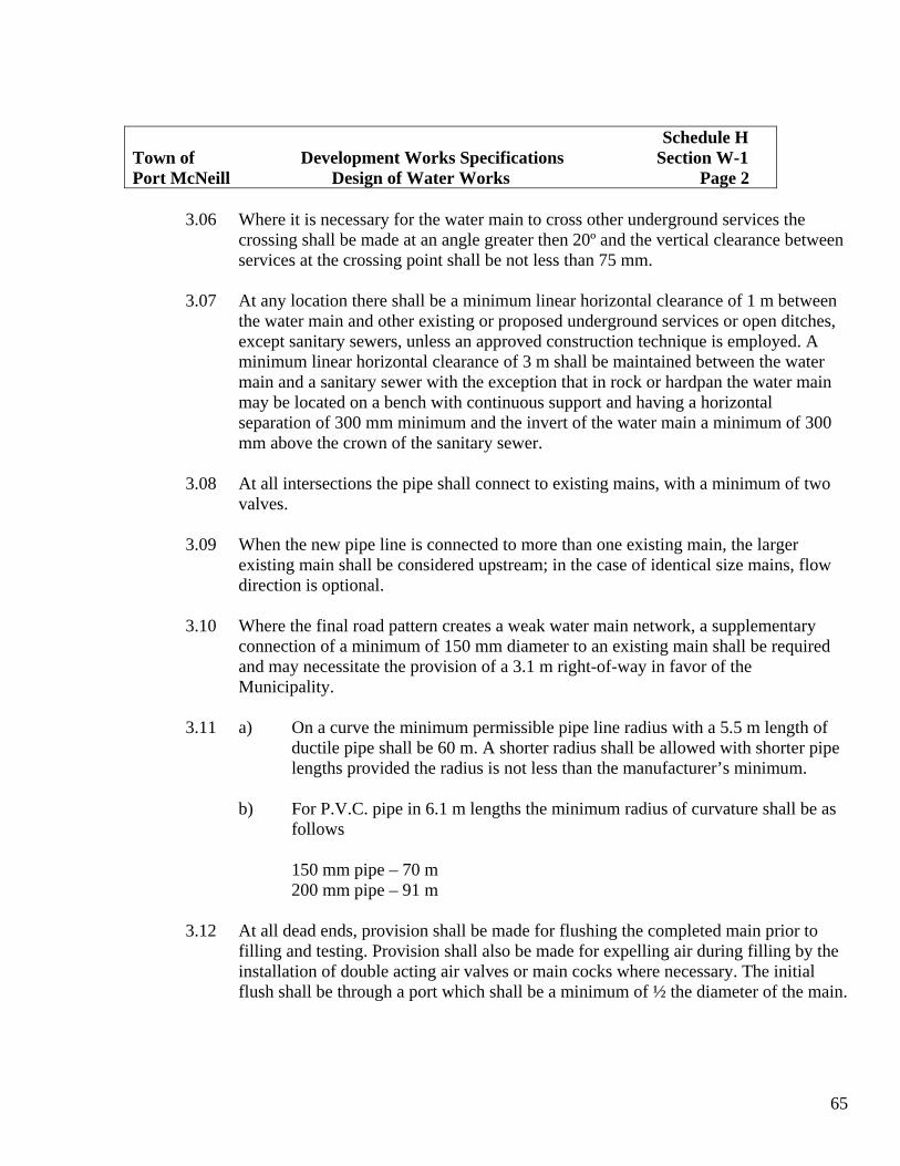
65
Schedule H Town of Development Works Specifications Section W-1 Port McNeill Design of Water Works Page 2
3.06 Where it is necessary for the water main to cross other underground services the
crossing shall be made at an angle greater then 20º and the vertical clearance between services at the crossing point shall be not less than 75 mm.
3.07 At any location there shall be a minimum linear horizontal clearance of 1 m between
the water main and other existing or proposed underground services or open ditches, except sanitary sewers, unless an approved construction technique is employed. A minimum linear horizontal clearance of 3 m shall be maintained between the water main and a sanitary sewer with the exception that in rock or hardpan the water main may be located on a bench with continuous support and having a horizontal separation of 300 mm minimum and the invert of the water main a minimum of 300 mm above the crown of the sanitary sewer.
3.08 At all intersections the pipe shall connect to existing mains, with a minimum of two
valves. 3.09 When the new pipe line is connected to more than one existing main, the larger
existing main shall be considered upstream; in the case of identical size mains, flow direction is optional.
3.10 Where the final road pattern creates a weak water main network, a supplementary
connection of a minimum of 150 mm diameter to an existing main shall be required and may necessitate the provision of a 3.1 m right-of-way in favor of the Municipality.
3.11 a) On a curve the minimum permissible pipe line radius with a 5.5 m length of ductile pipe shall be 60 m. A shorter radius shall be allowed with shorter pipe
lengths provided the radius is not less than the manufacturer’s minimum. b) For P.V.C. pipe in 6.1 m lengths the minimum radius of curvature shall be as
follows 150 mm pipe – 70 m 200 mm pipe – 91 m
3.12 At all dead ends, provision shall be made for flushing the completed main prior to filling and testing. Provision shall also be made for expelling air during filling by the installation of double acting air valves or main cocks where necessary. The initial flush shall be through a port which shall be a minimum of ½ the diameter of the main.

66
3.13 All water mains 200 mm diameter and larger shall be installed to a designed grade.
4.0 Pipe Size
4.01 Water mains shall be a minimum of 150 mm diameter. 4.02 Water service connections for single family residences or duplexes shall be 19 mm or
25 mm.
5.0 Materials
5.01 All pipe and fittings shall conform to the current C.S.A, A.W.W.A, or A.S.T.M. specifications for a working pressure of 1030 kPa. Where working pressure exceeds 1030 kPa, materials shall be subject to special design.
5.02 Ductile Iron pipe shall have a gasketed push-on joint and a cement mortar lining
conforming to A.W.W.A. Standard C151. Pipe shall have coal tar lining inside and out.
5.03 P.V.C. pipe shall conform to A.W.W.A. Standard 900-75 “Poly Vinyl Chloride”
(P.V.C.) Pressure Pipe 150 mm through 300 mm for water. The pipe is to be minimum class 150 [Dimensional Ratio (DR) of 18 maximum] with Ductile Iron outside diameter and Integral Bell Gasketed Joint. The pipe shall be supplied in 6.0 m nominal lengths.
5.04 19 mm and 25 mm water service tubing shall be series 160 Pacific “goldenflo” or
approved equal, and 39 mm and 50 mm water service tubing shall be Type K soft copper tubing (ASTM B.88-80) or approved equal.
5.05 Corporation stops and curb stops shall have compression type end fittings with rigid
stainless steel liners. 5.06 Single broad strap service clamps and bushings to match the pipe and connection
sizes shall be provided for each water service connection wherever asbestos cement pipe or PVC pipe is used.
5.07 Gate valves shall be standard, 860 kPa iron body, bronze mounted solid wedge or
double disc, parallel seat type with N.R.S turning counter-clockwise to open with 32 mm square operating nut. Resilient seat valves may be used for valves up to 50 mm in diameter.
Schedule H Town of Development Works Specifications Section W-1 Port McNeill Design of Water Works Page 3

67
5.08 A valve box shall be provided with each gate valve and as required for other
appurtenances. 5.09 Fire hydrants shall be 150 mm, tested for a working pressure of 1725 kPa and having
one 4 5/8 inch pumper port with 6 threads per inch and two 2 ½ inch hose ports set diagonally, with independent cut-off valve. The ports are to be threaded to the B.C. Standard and provided with caps. The operating nut is to be pentagonal with 25 mm sides turning counter-clockwise to open and the port caps shall have matching nuts. A drain valve shall be incorporated in the base of the hydrant.
6.0 Fire Hydrants
6.01 Hydrants shall be located in the boulevard and should preferably be located at or near a street intersection; otherwise they may be located on the projection of the property line dividing two lots. In selecting the location for a hydrant, the probable route of the fire engine shall be considered.
6.03 A hydrant shall not be located within 3 m of a utility pole or light standard, within 1
m horizontally of underground service pipes or open ditches, or within 2.2 m of the curb line.
6.04 Hydrants shall be located so that every home is within 120 m but with due regard to
the location of existing hydrants. Whenever practical, hydrants shall be near the highest and/or lowest point of the water main.
6.05 Additional hydrants may be required at school, apartment, commercial, or other high
valve properties. 6.06 There shall be a gate valve on the branch pipe to each fire hydrant. 6.07 All hydrants shall be set to finished grade. Any adjustments will be made by
Municipal forces at the Applicant’s expense.
7.0 Valves
7.01 Line valves shall be not more than 365 m apart. For convenience of operations, line valves should be located adjacent to a hydrant if there are no connecting mains within 120 m.
7.02 Line valves or hydrant valves shall not be located within 600 mm of a curb line, in a
ditch, or above another service.
Schedule H Town of Development Works Specifications Section W-1 Port McNeill Design of Water Works Page 4

68
7.03 A line valve of the same diameter as the pipe shall be placed on each downstream
branch of all “tee” and “cross” fittings. 7.04 Double acting air valves shall be installed at all high points on water main 200 m and
larger. 7.05 On service connections greater than 25 mm, a valve shall be placed on the connection
adjacent to the main.
8.0 Fittings
8.01 All fitting and appurtenances shall have standard hub ends or flanges where approved.
8.02 Standpipes shall be installed on all dead ends.
Schedule H Town of Development Works Specifications Section W-1 Port McNeill Design of Water Works Page 5

69
Schedule H Town of Development Works Specifications Section W-2 Port McNeill Installation of Waterworks Page 1
1.0 Scope
1.01 This specification shall govern the installation of all water pipe and waterworks appurtenances within the Municipality.
1.02 Water Services shall include that portion of the installation from, and including the
main stop up to and including the curb stop,
2.0 General
2.01 The installation, including jointing, shall be in accordance with the current A.W.W.A. Standards.
2.02 Ductile iron pipe shall be installed without joint conductance unless specifically
required for corrosion protection. 2.03 When the water main is under construction in a trench, water and debris shall be
prevented from entering openings in the water main by keeping the excavation sufficiently dewatered and also by capping or plugging such openings with watertight fittings. Pipe and fittings shall be protected from contamination during construction.
2.04 The 19 and 25 mm water service tubing shall be of one continuous piece between the
corporation stop and curb stop. 2.05 Existing valves shall not be opened or closed by unauthorized persons. 2.06 For existing 100 mm diameter pipe; 19 mm and 25 mm services shall be tapped a
minimum 600 mm apart, (and 600 mm from a collar) and rotated a minimum 100 mm on the circumference of the pipe. Larger services into pipes greater than 100 mm diameter shall be a minimum of 1.25 m apart. Service saddles shall be installed in all cases.
2.07 Where installation of other services cross under Asbestos Cement water mains, a
section of the A.C. main shall be replaced with Ductile Iron pipe such that the full trench width is bridged by Ductile Iron. This work shall be done by Municipal Crews at the applicant’s expense.
2.08 Blocking shall be installed as required. Concrete used for precast or in place blocking
shall have a minimum 20 MPa compressive strength.

70
Schedule H Town of Development Works Specifications Section W-2 Port McNeill Installation of Waterworks Page 2
2.09 The pipe shall not be backfilled until it has been inspected, approved, and the horizontal and vertical alignment recorded by the Consulting Engineer.
2.10 Curb stops shall be left exposed until testing and flushing is completed, then buried.
3.0 Location
3.01 The main and appurtenances shall be located to within 60 mm horizontally of the position shown on the approved plan.
3.02 The curb stop shall not be more than 400 mm outside of the front property line and a
minimum of 1.0 m from an iron pin. 3.03 Water service connections shall be installed from the water main to the property line,
using the shortest and straightest route. 3.04 All pipe shall be laid to designed alignment and grade with the following tolerances:
a) Horizontal tolerance shall not be greater than 60 mm from designed location. The rate of deviation from the required alignment shall not exceed 30 mm in 7.5 m.
b) Vertical tolerances shall not be greater than 10 mm from designed grades on
200 mm and greater water mains.
3.05 The ditch excavation shall be deep enough to allow a minimum of 1 m of cover material to be placed over the water main and water service except the curb stop which shall have 250 mm cover.
3.06 When the water main is within the road allowance, it shall be a minimum of 1 m
below the final road grade.
4.0 Bedding
4.01 Bedding for all water pipe shall conform to Class B bedding.
5.0 Testing
5.01 All water service connections shall be installed prior to pressure testing of the water mains.

71
5.02 After the pipe has been laid and backfilled or partially backfilled, all newly laid pipe
and hydrants shall be subjected to a hydrostatic pressure of 1030 kPa for 1 hour duration. Before applying the specified test pressure, all air shall be expelled from the pipe. If permanent air vents are not located at all high points, the Contractor shall install main stops at such points as to allow air to expel as the line is filled. After the air is expelled, the main stops shall be closed and the test pressure applied using a pump connected to the pipe. The test pressure shall be corrected based on the elevation of the lowest point of the section under test and the elevation of the test gauge. The pump, pipe connection including any necessary taps, and all necessary apparatus, shall be furnished by the Contractor.
All exposed pip, fitting, valves, hydrants, and joints shall be carefully examined
during the open trench test. All defects shall be remedied or replaced by the Contractor. The test shall be repeated until satisfactory results are achieved.
5.03 A leakage test shall be conducted after the pressure test has been satisfactorily
completed. Preliminary tests shall be done by the Contractor at his own expense. After a satisfactory test has been achieved, the Contractor shall notify the Municipality for a final test. The Contractor shall furnish the pump, pipe, connections and all other necessary apparatus and shall furnish the necessary assistance to conduct the test. A minimum pressure of fifty percent greater than the operating pressure at the lowest elevation of the system being tested shall be maintained during the test.
No pipe installation will be accepted if the leakage is greater than that shown in Table
A. The Contractor shall, at his own expense, locate and repair defective joints until the
leakage is within the specified limits. 5.04 Upon completion of the backfilling and satisfactory test results the water system shall
be flushed clean of any debris.
6.0 Chlorination
6.01 Chlorination shall be performed by the Contractor. 6.02 Chlorination shall be in accordance with AWWA Standard C601, generally as
follows:
Schedule H Town of Development Works Specifications Section W-2 Port McNeill Installation of Waterworks Page 3

72
Schedule H Town of Development Works Specifications Section W-2 Port McNeill Installation of Waterworks Page 4
- The initial chlorine concentration within the water main to be not less than 50
mg/l. - After minimum of 24 hours the chlorine residual shall not be less than 10
mg/l. - All valves and hydrants in the test section are to be separated during the
disinfection period. On completion of Chlorination, the entire pipe system shall be thoroughly flushed to remove all chlorinated water. Chlorinated water shall be disposed of away from water courses occupied by fish.
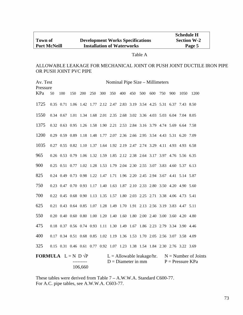
73
Schedule H Town of Development Works Specifications Section W-2 Port McNeill Installation of Waterworks Page 5
Table A
ALLOWABLE LEAKAGE FOR MECHANICAL JOINT OR PUSH JOINT DUCTILE IRON PIPE OR PUSH JOINT PVC PIPE Av. Test Nominal Pipe Size – Millimeters Pressure KPa 50 100 150 200 250 300 350 400 450 500 600 750 900 1050 1200 1725 0.35 0.71 1.06 1.42 1.77 2.12 2.47 2.83 3.19 3.54 4.25 5.31 6.37 7.43 8.50 1550 0.34 0.67 1.01 1.34 1.68 2.01 2.35 2.68 3.02 3.36 4.03 5.03 6.04 7.04 8.05 1375 0.32 0.63 0.95 1.26 1.58 1.90 2.21 2.53 2.84 3.16 3.79 4.74 5.69 6.64 7.58 1200 0.29 0.59 0.89 1.18 1.48 1.77 2.07 2.36 2.66 2.95 3.54 4.43 5.31 6.20 7.09 1035 0.27 0.55 0.82 1.10 1.37 1.64 1.92 2.19 2.47 2.74 3.29 4.11 4.93 4.93 6.58 965 0.26 0.53 0.79 1.06 1.32 1.59 1.85 2.12 2.38 2.64 3.17 3.97 4.76 5.56 6.35 900 0.25 0.51 0.77 1.02 1.28 1.53 1.79 2.04 2.30 2.55 3.07 3.83 4.60 5.37 6.13 825 0.24 0.49 0.73 0.98 1.22 1.47 1.71 1.96 2.20 2.45 2.94 3.67 4.41 5.14 5.87 750 0.23 0.47 0.70 0.93 1.17 1.40 1.63 1.87 2.10 2.33 2.80 3.50 4.20 4.90 5.60 700 0.22 0.45 0.68 0.90 1.13 1.35 1.57 1.80 2.03 2.25 2.71 3.38 4.06 4.73 5.41 625 0.21 0.43 0.64 0.85 1.07 1.28 1.49 1.70 1.91 2.13 2.56 3.19 3.83 4.47 5.11 550 0.20 0.40 0.60 0.80 1.00 1.20 1.40 1.60 1.80 2.00 2.40 3.00 3.60 4.20 4.80 475 0.18 0.37 0.56 0.74 0.93 1.11 1.30 1.49 1.67 1.86 2.23 2.79 3.34 3.90 4.46 400 0.17 0.34 0.51 0.68 0.85 1.02 1.19 1.36 1.53 1.70 2.05 2.56 3.07 3.58 4.09 325 0.15 0.31 0.46 0.61 0.77 0.92 1.07 1.23 1.38 1.54 1.84 2.30 2.76 3.22 3.69 FORMULA L = N D √P L = Allowable leakage/hr. N = Number of Joints --------- D = Diameter in mm P = Pressure KPa 106,660 These tables were derived from Table 7 – A.W.W.A. Standard C600-77. For A.C. pipe tables, see A.W.W.A. C603-77.

74
Schedule H Town of Development Works Specifications Section T-1 Port McNeill Trench Excavation, Backfilling & Cleanup Page 1
1.0 Scope
1.01 This specification shall govern the excavation, backfilling and clean up for utility trenches within the Municipality. This relates to backfill above the pipe zone and below the finished surface.
2.0 Excavation
2.01 The trench shall be excavated to the required alignment, width, depth, and grade as shown on the approved design drawings.
2.02 Excavated material shall not be stockpiled on the roadway. 2.03 Where the maximum trench width is exceeded, reference must be made to the
Consulting Engineer who shall obtain the approval of the Municipal Engineering Advisor before further construction may continue.
2.04 If the bottom of the trench is organic or other unsuitable material, the trench shall be
over excavated to firm ground and backfilled with suitable compacted material for pipe support, unless otherwise specified by the Consulting Engineer.
2.05 Trench water must be removed. 2.06 All solid rock boulders and large stones shall be removed to provide a minimum
clearance of 150 mm around the pipe. 2.07 Where an existing structure or underground installation may be affected by the works,
it is the responsibility of the Consulting Engineer to inform the owner of such utility sufficiently in advance to enable the owner to specify what protective measures must be taken.
3.0 Backfill
3.01 Where a pipe or conduit is installed beneath an existing or foreseeable future pavement, sidewalk, driveway or gravel shoulder, and the backfill shall be pitrun gravel or equal, compacted to a minimum 95% Standard Proctor Density, except for the top 300 mm which shall be 100 %.
3.02 Suitable native materials may be used as backfill where the pipe or conduit is
installed in non-travelled areas. Backfill in these cases shall be free of stones over 150 mm size, frozen material, organic, or other perishable or objectionable material that would prevent proper consolidation or which might cause subsequent settlement.

75
3.03 Controlled density backfill may be used in lieu of compacted gravel backfill.
Controlled density or unshrinkable fill shall be manufactured and placed in accordance with Canadian Portland Cement Association publication CP004.01P.
3.04 Where it is required to replace topsoil it shall occupy the upper 300 mm of the trench
and shall be mounded on top to allow for settlement. If the installation is under a developed lawn, the soil shall be fine raked during the appropriate season and sown with a top quality grass seed at the rate of 50 grams of seed per square metre and rolled.
4.0 Cleanup
4.01 Gravel filled trenches shall be maintained to within 25 mm of the original surface prior to final paving.
4.02 Patching cuts in existing pavement.
a) Cuts must be hot mix paved within 3 days of backfilling. b) If weather conditions do not permit hot-mix asphalt, cuts shall be paved
within 3 days of backfilling using cold-mix asphalt and replaced as weather permits.
c) Where the excavation is on the shoulder or under the travelled portion of the
street, the surface material shall be cut in neat straight lines at the edges of the trench by means of an asphalt cutting wheel, milling machine or pneumatic pavement breaker. Where the edges of any area requiring repaving extend outside the straight lines cut; further cuts shall be made so that the final patch will have a neat appearance.
d) Any area of pavement adjacent to the excavation which has become
undermined or deformed due to excavation practices or blasting shall be removed and repaved as above.
e) The pavement of cuts which have settled shall be removed, the trench shall be
recompacted and repaved.
5.0 Testing
5.01 The Consulting Engineer shall, at his direction, arrange for periodic compaction testing within the trench where trenchs are over 1.5 metres deep. Test results shall be submitted to the Municipality.
Schedule H Town of Development Works Specifications Section T-1 Port McNeill Trench Excavation, Backfilling & Cleanup Page 2

76
Schedule H Town of Development Works Specifications Section R-1 Port McNeill Design of Roads and Sidewalks Page 1
1.0 Scope
1.01 This specification shall govern the design of all roads, sidewalks, and appurtenances within the Municipality.
2.0 Classification and Width
2.01 Prior to design, the Municipality will classify and stipulate widths for the particular road under consideration.
2.02 Road Design Minimum Water Shoulders/ Width km/h R/W Control Boulevards Width
Cul-de-sac 8.5m 50 20m٭ Conc. curb 2.5m & gutter Residential 8.5m 50 20m Conc. curb 2.5m Urban & gutter Collector 11.0m 50 20m Conc. curb 2.5m & gutter Major Road Special Design Right-of-way for cul-de-sacs or non-extendible roads ٭ not greater than 150m in length. 3.0 Vertical Alignment
3.01 The vertical alignment of the road shall be set to serve adjacent properties with access driveways at a grade not steeper than 15% and conforming to the requirements as shown in Municipal Standard Drawing R10.
3.02 The length of a vertical curve shall be calculated using Municipal Standard Drawing
R7. 3.03 Vertical Control Maximum grade – Residential 15.0% Maximum grade – Collector 12.0% Minimum grade 0.5%

77
Minimum grade at curb returns 0.5% Maximum grade on turn around 8.0% at cul-de-sac Maximum grade at residential 5.0% for 15m tangent approach to collector length back from intersecting
road edge
Maximum grade at residential 3.0% for 15m tangent collector approach to major road length back from intersecting
road edge. Normal Crown 2.0%
3.04 Crossfall – the practice of cross falling a road is acceptable at intersections and where required because of topographical features.
3.05 Superelevation – horizontal curves on residential roads are not to be superelevated.
Collector and arterial roads shall be superelevated in keeping with the requirements of Municipal Standard Drawing R8.
3.06 Transition – the length of a transition from a normal cross-sectioned road to a section
of road where there is superelevation shall in no case be less than 45 metres. 3.07 Extensions – evidence that vertical alignments are satisfactorily extendible will be
required.
4.0 Horizontal Alignment
4.01 The horizontal alignment of the road shall be centred in the road allowance. Typical locations of services for new residential and collector roads are shown on Municipal Standard Drawing R3.
4.02 Centerline chainage stations shall be referenced and dimensioned from an identifiable
survey post. 4.03 Minimum radius of curve and maximum super elevation: DESIGN SPEED MINIMUM MAXIMUM km/h CENTERLINE RADIUS SUPERELEVATION Residential 50 90m٭ Normal Crown Collector 50 100m٭٭0.06 ٭ Major Road Special Design
Schedule H Town of Development Works Specifications Section R-1 Port McNeill Design of Roads and Sidewalks Page 2

78
Subject to the approval of the Municipal Engineering Advisor, curves on crescent shaped ٭residential roads may be reduced to a minimum centerline radius equal to 30m. .Refer to Municipal Standard Drawing R8 ٭٭ 4.04 A horizontal curve shall be fully described showing: internal angle, radius, tangent
length, and arc. 4.05 Curb returns of 8m radius are required for residential road intersections. Curb returns
located on bus routes and on roads within industrial and commercial districts require a 10m or larger radius to facilitate trucks and bus traffic.
4.06 When a new residential road with curbs intersects an existing road without curbs, the
curb returns shall not be constructed. However, curb returns shall be constructed at the intersection of two curbed roads.
5.0 Cross Section
5.01 The cross section of roads shall be designed in accordance with the dimensions and requirements shown on the following Municipal Standard Drawings:
TYPICAL SECTION STANDARD DRAWING
8.5m Residential Road (with curb and Gutter) R1 8.5m Residential Road (no curb & gutter) R2
5.02 Reference to or details of the cross-section dimensions and requirements must be shown on each design drawing.
5.03 The toe of a fill slope or top of a cut slope shall not encroach on private property. The
containment of these slopes within the road allowance may require the design of a retaining wall or the widening of the right-of-way to contain the cut or fill slope.
5.04 Where cut slopes are to be made into ground seepage zones or where the extent of the
slope would generate surface runoff, curtain drains shall be required at the base of the slopes and connected to the road drainage system or other suitable point of discharge.
6.0 Geometric Layout of Turn-Arounds
6.01 The design of the turn-around shall conform to Municipal Standard Drawing R4. The dimensions may be increased to meet traffic and vehicular requirements, or where the turn-around is skewed. Under special circumstances the Municipal Engineering Advisor may permit a temporary turn-around type of design.
Schedule H Town of Development Works Specifications Section R-1 Port McNeill Design of Roads and Sidewalks Page 3

79
6.02 The landscape design of the turn-around shall conform to Municipal Standard Drawing R4.
6.03 The design of a temporary turn-around shall conform to Municipal Standard Drawing
R5.
7.0 Curb and Gutter and Sidewalks
7.01 Mountable concrete curb and gutter shall conform to Municipal Standard Drawing R9 or R10.
7.02 Non-mountable concrete curb and gutter shall conform to Municipal Standard
Drawing R11. 7.03 Asphalt water control shall be constructed as necessary to direct flows into private
outlets. 7.04 Concrete invert gutter shall conform to Municipal Standard Drawing R9. 7.05 Mountable curbs and non-mountable curb returns shall be specified for residential
streets and non-mountable curbs elsewhere, except as required by the Municipal Engineering Advisor.
7.06 Sidewalks, where required, are normally located adjacent to the curb and shall be
1.5m wide. Sidewalks are to be crossfalled towards the road at 2%. 7.07 Gutters having widths less than those shown on Standard Drawings R9 and R10 will
be permitted for hand formed curbs, providing two #4 reinforcing bars are installed. In this case the curb shall conform to Standard Drawing R9 or R10 with a 200mm gutter width.
8.0 Catch Basins
8.01 Catch basins shall be constructed as shown on Municipal Standard Drawings SD10, SD11, and SD12.
8.02 Double catch basins should be installed at locations of high runoff and sag curves. 8.03 Catch basins shall be located at the higher end of the curb returns of intersections, at
the lowest point of the sag vertical curves, and at a spacing not greater than the following:
Schedule H Town of Development Works Specifications Section R-1 Port McNeill Design of Roads and Sidewalks Page 4

80
MAXIMUM SPACING OF CATCH BASINS
ROAD WIDTH SPACING 8.5m 90m 11.0m 75m On roads with superelevation crossfall the maximum spacing shall be one-half of the
above figures. Adequate allowance shall be made to handle runoff from turn-arounds. Exceptions to the above maximum spacing of catch basins may be allowed, where
paving is to be installed on existing streets and where houses are drained in a manner satisfactory to the Municipal Engineering Advisor.
9.0 Appurtenances
9.01 a) The Consulting Engineer shall detail on the design drawing the location of all retaining walls, guardrails, handrails, and fences. These structures shall be designed in keeping with good engineering practices.
b) The design of barricades, chain link fence and sidewalk handrails shall conform to
Municipal Standard Drawings R16, R17, and R18, respectively. 9.02 The Consulting Engineer shall indicate utility poles which must be relocated prior to
road construction and he shall confirm with the appropriate utility representatives the feasibility of their relocation prior to design completion.
9.03 Underground Wiring – the Consulting Engineer shall indicate on his design drawing
the designs supplied by B.C. Hydro or B.C. Telephone for all underground wiring which require relocation or are proposed including the connection to properties.
10.0 Structural Design of Roads
10.01 All road base and paving design shall be in accordance with Appendices 1 to 8 inclusive of these specifications.
10.02 The compacted gravel base and asphalt pavement thickness requirements for various
road classifications are shown on the following Municipal Standard Drawings.
Schedule H Town of Development Works Specifications Section R-1 Port McNeill Design of Roads and Sidewalks Page 5
81
Classification Standard Drawing
8.5m Residential Road (with curb & gutter) R-1 1.0m Collector Road (with no curb & gutter) R-2
10.03 The following criteria shall be followed for structural design of roads. Asphalt Pavement Design – accepted references “A Guide to the Design of Flexible and Rigid Pavements in Canada” – RTAC 1971 “Asphalt Overlays and Pavement Rehabilitation.” The Asphalt Institute 1977 MS – 17. 10.04 The structural design of the road pavement shall be adequate for a 20 year life under
the expected traffic conditions. 10.05 Regardless of the method of design used, the maximum Benkelman Beam deflection
(corrected for seasonal variation) on the finished pavement when tested for final acceptance by the Consulting Engineer shall be not greater than 1.8 mm for subdivision roads.
10.06 The minimum total flexible pavement structure thickness for any local road shall be
in accord with Standard Drawings regardless of the structural design requirements determined by the Benkelman Beam or CBR method of design.
10.07 Other than for isolated shoulder widening, whenever a pavement is being widened, a
minimum overlay of 25 mm of asphalt for blending and levelling purposes shall be required over the full pavement width to the centerline of the pavement.
10.08 Deep strength asphalt designs are acceptable provided the minimum thickness for the
pavement structure as shown in Standard Drawings is met. 10.09 Road reconstruction and asphalt overlay design shall be based on the analysis of the
results of Benkelman Beam tests and test holes carried out on the existing road which is to be upgraded, or by the CBR asphalt pavement design method.
10.10 The design for new roads shall be based on the analysis of the results of Benkelman
Beam tests and test holes carried out on adjacent roads having similar subgrade soil conditions as the proposed road or by the CBR asphalt pavement design method. The results shall be supplemented by analysis of material taken from test holes dug on the
Schedule H Town of Development Works Specifications Section R-1 Port McNeill Design of Roads and Sidewalks Page 6

82
proposed road site at intervals of approximately 80 metres, including soils classification, carried out by a qualified soils testing company.
10.11 Benkelman Beam tests shall be carried out in accordance with the procedures outlined in the “Roads and Transportation Association of Canada Technical Publication No. 12”
Seasonal variation of Benkelman Beam results is not normally a factor in the
Municipality. In the event of readings in freeze – thaw or extended wet periods of weather, a seasonal correction factor of 1.2 should be applied to produce most probable spring rebound (MPSR) values for design.
Schedule H Town of Development Works Specifications Section R-1 Port McNeill Design of Roads and Sidewalks Page 7

83
Schedule H Town of Development Works Specifications Section R-2 Port McNeill Construction of Roads and Sidewalks Page 1
1.0 Scope
1.01 This specification shall govern the construction of roads, sidewalks, and appurtenances within the Municipality.
2.0 Clearing
2.01 The full width of the roadway and shoulders shall be cleared of timber and bush which shall be removed. All topsoil will be removed to at least 2.5m clear of the curbs. Sufficient topsoil must be retained on site for 200mm of topsoil on the boulevard. Surplus topsoil which may have to be removed from an existing road allowance is the property of the Municipality and shall be deposited at a stock pile site approved by the Municipality.
2.02 The remaining portion of road allowance will be cleared of stumps, rubble, and loose
rock and rough graded to the satisfaction of the Consulting Engineer. Finished grading, seeding of grass and rolling adjacent to any road construction on established boulevards or where otherwise required by the Consulting Engineer shall be done upon completion of all construction.
3.0 Setting of Grades
3.01 Grade hubs will be set at not more than 10m intervals on tangents and 5m intervals on curves on both sides of the road and at the same chainage points. Hubs will be located so that they are not disturbed by the construction equipment.
3.02 On horizontal curves the increased or decreased arc shall be calculated to compensate
for the radius so that the hubs on both sides of the road will bear the same center line chainage.
3.03 Where the road is to be superelevated it may be necessary to calculate the difference
in elevation due to the offset of the hub to enable the sub-base to be graded. Care should be taken to ensure that this compensated elevation is not used when the concrete curbs are being formed.
3.04 Sturdy hubs of sufficient length to give firm footing shall be used with nails driven in
the top for fine alignment, and suitably identified which chainage, cut or fill, and offset to curb face. Cut or fill information will face the hub and will be related to the elevation to the top of curb.

84
3.05 Cross heads may be erected at a suitable height at every station, clearly marked for
the amount of cut or fill required to finish grade. Cuts or fills should be adjusted to even vertical intervals above required grade. Grades should be checked with a boning rod by sighting across these cross heads.
3.06 Alternate methods of layout and construction may be used providing the curbs or
centerline is within 15mm of the design elevation and 30mm of the design horizontal alignment.
4.0 Sub grade Construction
4.01 All topsoil, trees, stumps, soft material and soil containing organic matter shall be stripped from all areas to be occupied by fills, road shoulders, road surfaces, and side ditches.
4.02 Where required by the Consulting Engineer, the stripped areas shall be excavated to
remove all soil not capable of accepting the loads to be imposed upon it by the road embankment.
4.03 The sub grade shall be constructed of granular or other material approved by the
Consulting Engineer, placed in layers not exceeding 150mm and compacted to 95% of the laboratory density obtained by the following A.S.T.M Specification 698. Method C, or latest revision thereof with exception of the top 300mm which shall be compacted to 100%. The fill section shall conform to Municipal Standard Drawing R1, R2, R3, and R4.
4.04 In cuts, the top 300mm of the sub grade will be compacted to 100% of the laboratory
density obtained by following A.S.T.M Specification 698, Method C, or latest revision thereof, when required by the Consulting Engineer. The cut section shall conform to Municipal Standard Drawings R1, R2, R3, and R4.
4.05 The toe of the fill slope or the top of a cut shall not extend outside the right-of-way.
The containment of these slopes may require the construction of retaining walls, rip-rap, or the right-of-way could be widened.
4.06 No topsoil, trees, stumps or any organic matter will be buried in the subgrade, sub-
base or base course. 4.07 Rock shall be excavated to depths shown on Municipal Standard Drawings R1, R2,
R3, and R4.
Schedule H Town of Development Works Specifications Section R-2 Port McNeill Construction of Roads and Sidewalks Page 2

85
5.0 Base Course and Sub-Base Preparation
5.01 Where native material is unacceptable to the Consulting Engineer for constructing a compacted subgrade in cuts or fills, a sub-base of acceptable granular materials will be placed between the subgrade and base course. Select granular material from road cuts or 80mm minus pit run gravel either being acceptable to the Engineer may be used as sub-base material.
5.02 The sub-base will be constructed of granular or other approved material placed in
layers not exceeding 150mm and compacted to 95% of the laboratory density obtained by following A.S.T.M. Specification 698, Method C, or latest revision thereof with exception of the top 300mm which shall be compacted to 100%. The fill section shall conform to Municipal Standard Drawings R1, R2, R3 and R4.
5.03 Granular surfacing, base course and sub-base preparation shall conform to Appendix
2 of these Specifications. 5.04 In addition to the requirements of Appendix 2 the field density of soils shall be
determined by A.S.T.M designation D2922, determining density of soil and soil aggregate in place by nuclear methods (shallow depth).
For spot checks, the following methods are also acceptable: A.S.T.M Designation D 1556 - Density of soils in place by sand cone method. A.S.T.M Designation D 2167 - Density of soils in place by rubber balloon method. 5.05 No base course gravel shall be placed until all underground services have been
installed unless otherwise approved by the Consulting Engineer. 5.06 The 80mm crushed pit run as described in Appendix 2, Section 2.02 may be specified
by the Consulting Engineer for the road base course and/or sub-base, on slopes of large embankments, on areas of poor sub-grades, and special conditions where increased stability is required.
6.0 Sidewalks, Curbs and Gutters and Catch Basins
6.01 Concrete – concrete shall conform to the requirements outlined in Appendix 8 of these Specifications.
Schedule H Town of Development Works Specifications Section R-2 Port McNeill Construction of Roads and Sidewalks Page 3

86
6.02 Concrete sidewalks, curb and gutter, and driveway crossings will be constructed in
accordance with the following Standard Drawings: Curb and Gutter – Mountable R9 or R10 Curb and Gutter – Non Mountable R11 Curb, Gutter and Sidewalk – Combined R12 Sidewalk – Concrete R12 The type of construction to be used and the location will be as shown in the
construction design drawings or as directed by the Consulting Engineer. 6.03 Extruded Sidewalk, Curb and Gutter
a) The Contractor will be given the option of constructing extruded curb and gutter. Prior to use, the specifications for the extrusion equipment shall be submitted for written approval from the Consulting Engineer. Automatic grade and line control will be required.
b) Extruded concrete shall be finished as shown in the applicable drawings, with
a surface grade brush finish; a dense uniform surface will be required on curb and gutter.
6.04 Placing of Concrete
a) After mixing, the concrete shall be transported rapidly to the job site, and shall be delivered as close as possible to the point of deposit. Rehandling of concrete will not be permitted.
b) Concrete operations shall be continuous until the section, panel, or scheduled
pour is completed. Should the operation be unavoidably interrupted, fully depth construction joints shall be formed at the proper locations as herein specified.
c) The concrete shall be placed in such a manner as to prevent separation of the
ingredients. Special care shall be taken to place the concrete against the forms, particularly in corners, in order to prevent voids, rough areas, and honeycombing.
d) The concrete shall be placed to the full specified depth. After spreading, the
concrete shall be struck-off and compacted by means of an approved screed. Vibrators or vibrating screeds are recommended and shall be operated at a
Schedule H Town of Development Works Specifications Section R-2 Port McNeill Construction of Roads and Sidewalks Page 4

87
minimum of 5000 cycles per minute. The technique and use of vibrators of vibrating screeds shall be at the discretion of the Consulting Engineer.
e) Freshly placed concrete shall be protected in an approved manner against
damage from the elements, and construction operations harmful to concrete.
6.05 Trowelling and Brushing Finish
a) After placing, the concrete shall be adequately worked with wood and steel trowels to a smooth finish with the required edges neatly rounded. Excessive troweling is to be avoided.
b) The use of grid tampers or “Bird Cages” will not be allowed. c) If there is evidence of concrete bleeding, finishing shall cease until the excess
water has evaporated to the satisfaction of the Consulting Engineer. Failure to comply with the above will result in complete replacement of the sections involved.
d) Brush finish shall be applied with a nylon bristle brush approved by the
Consulting Engineer. The brushing shall be carried out in accordance with applicable drawings and in such a manner and at such a time as to minimize the depth and quantity of brush marks. All surplus water must be removed from the bristles before brushing commences. No mortar coat or water wash shall be used.
e) Catch basin gutter grates shall be removed while finishing the adjacent gutter,
and replaced following completion of finishing. f) After troweling, the surface grade along the lip of gutter shall be checked by
the Contractor with straights edges, to an accuracy of plus or minus 10mm in 3 meters. The maximum allowable variation across the gutter shall be 3mm.
6.06 Forms 6.06.1 Construction of Formwork – Forms shall be of metal or timber properly seasoned and
free from warps or other defects. The type and section of the metal forms shall require the approval of the Municipal Engineer. The face of curb forms shall be removable without disturbing back and gutter forms. The forms shall be smooth and clean on the surface(s) next to the concrete and shall be oiled with Parvelube No. 30 or approved equal. The forms shall be rigidly held true to the established lines and grades.
Schedule H Town of Development Works Specifications Section R-2 Port McNeill Construction of Roads and Sidewalks Page 5

88
6.06.2 Stripping of Forms
a) Face of curb forms shall be removed after the initial set. Adequate care shall be taken in removing forms to avoid spoiling or marring the concrete. Such patching as may be necessary shall be started immediately after removal of the forms.
b) Immediately after form removal and/or patching, the exposed surfaces shall be
sprayed with the membrane curing material.
6.07 Joints 6.07.1 Contraction Joints
a) Contraction joints shall be cut at every 3m by means of a marking tool or other approved method. Joints shall not be less than 30mm in depth and 7mm in width.
b) The edges of the joint shall be rounded off with an edger having the arc of a
circle of 7mm radius. c) Contraction joints in a monolithic sidewalk must extend through the full width
of the side walk and curb and gutter. d) Contraction joints at catch basins shall be cut through the full width of the
sidewalk in line with both outside edges of the catch basin gutter frame.
6.07.2 Expansion Joints – Lateral expansion joints are required at the beginning and end of every corner. The joint shall consist of an approved mastic preformed material, 13mm, 90mm cross-section, laid plumb and straight, 7mm below the finished sidewalk grade.
6.07.3 Surface Joints – Surface joints 13mm in depth and 7mm in width will be cut in the
sidewalk sections only every 3 meters in between the contraction joints. The edge of the joint shall be rounded off with an edger having an arc or a circle of 7mm radius.
6.07.4 Sawed Joints – Saw cuts as specified are to be made with a special concrete saw
capable of producing a true straight joint of constant depth as required
Schedule H Town of Development Works Specifications Section R-2 Port McNeill Construction of Roads and Sidewalks Page 6

89
6.07.5 Breaking Out – All breakout shall end at a contraction, expansion or surface joint.
The edge of a surface joint is to be sawn to a depth of 22mm minimum, while contraction joints may be neatly hand chiseled.
6.07.6 Obstructions
a) The contractor will be required to carefully fit, cut and mark a surface joint in the sidewalk around all openings, iron covers, manholes, vaults, valves or meter boxes, lamp standards, hydrants, poles and other surface installations. The surface joint must be neatly tooled to the satisfaction of the Consulting Engineer.
b) Expansion joints material, 13mm thick and the full depth of the sidewalk,
shall be placed around the base of all poles, hydrants, and where the work abuts existing buildings or other structures, including existing sidewalks.
6.08 Reinforcing 6.08.1 General
a) Reinforcing shall be clean and free from defects, kinks, loose rust of mill scale at the time the concrete is places. Any coatings of hardened mortar shall be removed from the steel.
b) Bar reinforcing shall meet A.S.T.M. Specification A184 and A.S.T.M.
Specification A304, intermediate grade new billet deformed steel. c) Cold-drawn steel wire shall meet the requirements of A.S.T.M. Specification
A82 and the wire mesh shall meet the requirements of A.S.T.M. Specification A185.
6.08.2 Reinforced Driveway Crossings
a) In separate sidewalk, combined sidewalk, and curb and gutter, a single layer of 150mm by 150mm by 10/10 gauge wire mesh, in a minimum concrete depth of 150mm, as shown on Municipal Standard Drawings R12 shall be placed at public lanes, and all driveway crossings. The mesh shall extend to the full width of the crossing.
Schedule H Town of Development Works Specifications Section R-2 Port McNeill Construction of Roads and Sidewalks Page 7
90
b) In separate curb and gutter, two No. 4 reinforcing bars, as shown on
Municipal Standard Drawing R12, shall be placed at apartments and commercial driveways.
6.08.3 Reinforcing in Fill Areas – where the sidewalk, curb and gutter, combined sidewalk
curb and gutter, is constructed on more than 300mm of fill, or where poor soil conditions are evident, reinforcing steel shall be used.
a) In separate curb and gutter, two No. 4 reinforcing bars shall be placed, as
shown on Municipal Standard Drawing R11. b) In separate sidewalk, a single layer of 150mm by 150mm by 10/10 gauge wire
mesh shall be placed as shown on Municipal Standard Drawing R12. c) In combined sidewalk, curb and gutter, a single layer of 150mm by 150mm by
10/10 gauge wire mesh shall be placed as shown on Municipal Standard Drawing R12.
6.08.4 Placing of Reinforcement – Reinforcing mesh shall be rolled or otherwise
straightened to make a perfectly flat surface before placing. The mesh or bar reinforcing shall be supported above the compacted gravel base so as to ensure a 50mm cover of concrete. The manner of supporting the reinforcing shall be approved by the Consulting Engineer. Overlapping of mesh reinforcing shall be a minimum of 300mm and shall be wired together. Overlapping of bar reinforcing shall be thirty (30) bar diameters and shall be wired together.
6.08.5 Reinforcing Markings – All sections containing reinforcing shall be marked at their
extreme limits with a marking tool showing the letter R and arrow pointing in the direction of reinforcing. This letter shall be 4cm high.
6.09 Protection of Work 6.09.1 Covering- The Contractor shall supply and place all tarpaulins, or other necessary
materials to protect the work from in, dust, frost, or other similar weather action, for such time as the Engineer may consider necessary. Failure of the Consulting Engineer to order protection does not relieve the Contractor of the responsibility.
6.09.2 Barricades – The Contractor shall also barricade the work and keep all humans,
animals, and vehicles off the work for a period of five (5) days after the finishing of the concrete has been completed. Any damage occurring to the work during this five (5) day period regardless of origin shall be repaired by the Contractor to the
Schedule H Town of Development Works Specifications Section R-2 Port McNeill Construction of Roads and Sidewalks Page 8

91
satisfaction of the Consulting Engineer within one (1) month after notice is given to the Contractor.
6.09.3 Pedestrian and Vehicular Access – The Contractor shall ensure that affected property
owners are notified at least one day prior to the pouring of concrete and that alternate pedestrian access is provided. With respect to commercial properties, access must be maintained as directed by the Consulting Engineer. Inconvenience to the public shall be minimized.
6.10 Catch Basins
a) Construction of catch basins in the locations shown on the design drawing shall be undertaken prior to the construction of curbs.
b) Mountable concrete curb will have two #4 reinforcing bars placed as
shown in Standard Drawing R10 behind catch basins.
6.11 Curb and Gutter Transitions – Where dissimilar sections join, a uniform gutter grade shall be maintained and a suitable transition effected by adjusting the height of the curb within one metre.
7.0 Asphalt Paving
7.01 Asphaltic Materials – Asphaltic materials shall conform with the requirements in Appendix 1 – Asphaltic Materials.
7.02 Surface Preparation for Asphalt Paving – The surface for asphalt paving shall be
prepared in accordance with Appendix 3 – Surface Preparation for Asphalt Paving. 7.03 Asphaltic Concrete Paving – Asphaltic Concrete Paving shall be placed in accordance
with Appendix 4 – Asphaltic Concrete Paving. 7.04 Surface Treatment – Aggregate Seal Coats, Sand Seal Coats, Fog Seal Coats and
Slurry Seal Coats shall be placed in accordance with Appendix 5 – Surface Treatments.
7.05 Inspection and Testing – All asphalt paving shall be tested by a qualified laboratory in
accordance with Appendix 6 – Inspection and Testing and Appendix 7 – Asphalt Methods of Test. The testing laboratory shall be retained by the Consulting Engineer and shall send reports to the Municipality within 30 days of the test commencement.
Schedule H Town of Development Works Specifications Section R-2 Port McNeill Construction of Roads and Sidewalks Page 9

92
8.0 Appurtenances
8.01 Retaining walls, guardrails, handrails, fences, and barricades shall be installed in accordance with the design drawing and these specifications.
8.02 Handrails will be used on retaining walls with greater than 0.5m drop.
9.0 Cleaning Up
9.01 All surplus material, tools, temporary structures, debris, dirt and rubbish shall be promptly removed by the Contractor immediately following completion of the construction work.
9.02 The site shall also be left clean and tidy to the satisfaction of the Works Inspector.
10.0 Traffic Control
Appropriate traffic control shall be arranged by the Contractor.
11.0 Test Reports
Copies of all reports of tests required by this Section shall be submitted by the Consulting Engineer with the as-constructed drawings.
Schedule H Town of Development Works Specifications Section R-2 Port McNeill Construction of Roads and Sidewalks Page 10

93
Schedule H Section R-2 Town of Development Works Specifications Appendix 1 Port McNeill Asphaltic Materials Page 1
1.0 Preliminary and General
1.01 Scope
a) This Specification describes the requirements for the different types and grades of asphaltic materials and additives to be supplied for highway use.
b) The materials so described are generally classified as follows: Asphalt Cements; Liquid Asphalt; Emulsified Asphalt and Cationic
Emulsified Asphalt.
1.02 Quality Control Requirements
a) Quality Control System
1. The supplier shall develop and maintain an effective quality control system in accordance with the provisions of this Specification. The system shall ensure that adequate inspection coverage is maintained throughout the entire process of manufacture and shipping.
2. Supplies not conforming to these requirements shall not be offered for
use until the deviations have been authorized by the Consulting Engineer.
b) Quality Control Procedure – The supplier may be required to furnish the
Consulting Engineer with an outline of his quality control procedures detailing his method of implementing the requirements of this specification. This outline shall include the following operations: receiving, blending and processing, sampling and testing, storage and handling, shipping, recording and reporting.
1.03 Sampling and testing The supplier shall possess adequate sampling equipment, employ satisfactory
sampling procedures and maintain a suitable sampling program. Representative samples from filled shipping containers shall be examined by the Consulting Engineer to ensure quality. (Refer to Appendix 7 for Methods of Test.)

94
1.04 Delivery of Asphaltic Materials Temperature of Shipment – Where specified, bituminous material shall be shipped
hot. The temperature for shipment shall be subject to arrangement between the Contractor and supplier but generally the supplier should endeavour to ship bituminous materials at such temperatures that on arrival its temperature shall be such that the Kinematic Viscosity of material shall be as below:
Class of Materials Kinematics Viscosity, Centistokes liquid bitumen materials for surfacing spraying 100 – 200 Liquid bituminous material and asphalt cements for plant mixing purposes 150 – 400
Subject to the above requirements, asphalt shall normally be shipped within the temperature ranges given in the following table. In no case shall asphalt be shipped at a temperature greater than the designated maximum.
Loading Temperatures Min. C Max. C Paving Asphalt Cements 145 205
RC-70 50 80 RC-250 65 90 RC-800 80 105 RC-3000 105 135 MC-30 35 80 MC-70 50 80 MC-250 65 90 MC-800 80 105 MC-3000 105 135
SC-70 50 80 SC-250 65 120
SC-800 80 135 SC-3000 105 160
Special Prime 25 65
Schedule H Section R-2 Town of Development Works Specifications Appendix 1 Port McNeill Asphaltic Materials Page 2

95
RS-1 15 55 SS-I 15 55 SS-1h 15 55 CRS-1 15 55 RS-2 45 70 MS-2 45 70 MS-2h 45 70 CRS-2 45 70
2.0 Asphalt Cements
2.01 Asphalt Cements shall
a) be products prepared by the refining of crude petroleum. b) be homogenous, free from water and shall not foam when heated to 175ºF. c) be supplied in such grades as may be specified. d) comply with the following detailed requirements and the requirements of
A.S.T.M Specification D-946
Grade 60-70 85-100 120-150
Min Max Min Max Min Max
Penetration at 25 C 100g, 5 seconds 60 70 85 100 120 150
Flash point C (Cleveland open cup) 232.2 232.2 218.3
Ductility at 25C 50mm per min, mm 1000 1000 1000
Retained penetration after this-film over test, percent 52+ 47+ 42+
Solubility in trichloroethylene percent 99.0 99.0 99.0
Ductility at 25 C 50 mm/min., mm after thin-film oven test 500 750 1000
3.0 Liquid Asphalts
3.01 General Description
a) Liquid asphalts shall consist essentially of petroleum derivatives and shall be substantially free from water and other impurities.
b) Liquid asphalts shall be of the type and grade described in the following
tables, and shall comply with the requirements of A.S.T.M Specification
Schedule H Section R-2 Town of Development Works Specifications Appendix 1 Port McNeill Asphaltic Materials Page 3

96
D-2026 (slow-curing type), A.S.T.M. Specification D-2027 (medium-curing type) and A.S.T.M Specification D-2028 (rapid-curing type).
1. Slow Curing Type Liquid Asphalt.
Designation SC-70 SC-50 SC-800 SC-3000
Requirements Min Max Min Max Min Max Min Max
Kinematic Viscosity at 60 C, cSt. Flash point (Cleveland open cup) C Flash point (Cleveland open cup) C
70
65.5
140 250
79.4
500 800
93.3
1600 3000
107.2
6000
Distillation Test: Total Distillate to 360 C Percent by volume
10 30 4 20 2 12 5
Kinematic viscosity on distillation resideue to 60 C stokes
4 70 8 100 20 160 40 350
Asphalt Residue: Residue to 100 penetration, percent
50 60 70 80
* Ductility of 100 penetration residue at 25° C mm
1000 1000 1000 1000
Solubility in trichloroethylene 99.9 99.0 99.0 99.0
Water, percent 0.5 0.5 0.5 0.5
*Note: If the ductility at 25 C is less than 1000, the material will be acceptable if its ductility at 15.5 C is more than 1000 mm.
2. Medium-Curing Type Liquid Asphalt:
Designation MC-30 MC-70 MC-250 MC-800 MC-3000
Requirements Min Max Min Max Min Max Min Max Min Max
Kinematic viscosity at 60 C: 30 60 70 140 250 500 800 1600 3000 6000
Flash point (Tag open cup), C: 37.8 37.8 65.5 65.5 65.5
Distillate Test: Distillate, percent by volume of total distillate to 360 C:
to 225 C to 260 C to 316 C
40 75
25 70 93
20 65
20 60 90
15 60
10 55 87
45
35 80
15
15 75
Residue from distillation to 360 C percent volume by difference
50 55 67 75 80
Tests on residue from distillation: Penetration at 25 C, 100g, 5 sec.
120
250
120
250
120
250
120
250
120
250
Ductibility at 25 C, mm: 1000 1000 1000 1000 1000
Solubility in trichloroethylene, percent: 99.0 99.0 99.0 99.0 99.0
Water, percent 0.2 0.2 0.2 0.2 0.2
:Note ٭If the ductility at 25 C is less than 1000, the material will be acceptable if its ductility is at 15.5 C is more than 100 mm.
Schedule H Section R-2 Town of Development Works Specifications Appendix 1 Port McNeill Asphaltic Materials Page 4

97
3. Rapid Curing Type Liquor Asphalt
Designation MC-70 MC-250 MC-800 MC-3000
Requirements Min Max Min Max Min Max Min Max
Kinematic viscosity at 60° C, cSt.: 70 140 250 500 800 1600 3000 6000
Flash point (Cleveland open cup), C: 26.7+ 26.7+ 26.7+
Distillate Test: Distillate, percent by volume of total distillate to 360° C:
to 190 to 225 to 260 ro 316
10 50 70 85
35 60 80
15 45 75
25 70
Residue from distillation to 360° C percent volume by difference
55 65 75 80
Tests on residue from distillation: Penetration at 25° C, 100g, 5sec.
80 120 80 120 80 120 80 120
* Ductibility at 25° C, mm: 1000 1000 1000 1000
Solubility in trichloroethylene, percent: 99.0 99.0 99.0 99.0
Water, percent 0.2 0.2 0.2 0.2
* Note: If the ductility at 25° C is less than 1000, the material will be accewptable if its ductility at 15.5° C is more than 1000 mm.
3.02 Special Primer
DESIGNATION Min. Max. Kinematic Viscosity at 60º C- Centistokes 20 35 Distillate % by Volume of total distillate to 190 C to 225 C to 250 C to 315 C
40 70 85
50
Residue from distillation to 360º C,volume % by difference 50 Tests on residue from distillation to 360 Penetration at 25 C, 100g, 5 sec
80
200
* Ductility at 25 C, mm 1000 Solubility in Carbon Tetrachloride 99.5 Water, percent 0.2 Note: If the ductility at 25º C is less than 1000, the material will be acceptable if its ductility ٭
at 15.5º C is more than 1000 mm. Note: Viscosity of residue from distillation to 360º C will be measured at 60º C and
reported in stokes on each batch analysis report.
Schedule H Section R-2 Town of Development Works Specifications Appendix 1 Port McNeill Asphaltic Materials Page 5

98
3.03 Rubberized Cutback Asphalt R.R.C.
a) General Description – Rubberized Cutback Asphalt shall consist of a selected vacuum reduced asphalt containing a matched synthetic rubber, dispersed colloidally or in molecular solution at the refinery, and cutback with naphtha solvent to produce a range of cutback material having substantially similar properties to R.C. Cutback, except that the rubberized asphalt residue shall have considerable increased tenacity and toughness characteristics.
b) Tests- The rubberized asphalt residue shall, when tested by the Benson
Method and compared with the original asphalt base stock, show a minimum toughness of 200 percent and minimum tenacity of 1000 per cent.
c) Acceptance – The acceptance of any rubberized asphaltic material shall be at
the sole discretion of the Municipal Engineering Advisor.
4.0 Emulsified Asphalts
4.01 Types – Liquid bituminous materials in the form of aqueous emulsions shall be of the following:
a) Emulsified Asphalt
1. The emulsified asphalt shall be homogenous. It shall show no separation of asphalt after thorough mixing within thirty (30) days (crack filler twenty (20) days) after delivery, provided separation has not been caused by freezing.
2. The emulsion shall conform to the detailed requirements of the
following table, and the requirements of the A.S.T.M. Specification D-977.
Schedule H Section R-2 Town of Development Works Specifications Appendix 1 Port McNeill Asphaltic Materials Page 6

99
TYPE RAPID-SETTING MEDIUM SETTING SLOW-SETTING
GRADE RS-1 RS-2 MS-1 MS=2 MS=2h SS-1 SS-1h REQUIREMENTt Min. Max Min. Max Min. Max Min. Max Min. Max Min. Max Min. Max
CRACK FILLER
Tests on Emulsions: Viscosity, Saybolt Furol at 25 C, s 20 100 20 100 100 100 20 100 20 100 50-200 Viscosity, Saybolt Furol at 50° C, s 75 400 Settlement, 5 days, percent 5 5 5 5 5 5 5 3- Storage stability test, 1 day 1 1 1 1 1 1 1 Demulsibility, 35 ml, 0.02 N CaCl, percent
60 60
Coating ability and water resistance: Coating, dry aggregate good good good Coating after spraying fair fair fair Coating, wet aggregate fair fair fair Coating, after spraying fair fair fair Cement mixing test, percent 2.0 2.0 Sieve test, percent 0.1 0.1 0.1 0.1 0.1 0.1 0.1 Residue by distillation, percent 55 63 55 65 65 57 57 Tests on Residue from Distillation Test: Penetration, 25 C, 100g. 5 s 100 200 100 200 100 200 100 200 40 90 100 200 40 90 60-100 Ductility, 25 C 50mm/min. mm 400 400 400 400 400 400 400 Solubility in trichloroethylene, percent 97.5 97.5 97.5 97.5 97.5 97.5 97.5
b) Cationic Emulsified Asphalts – Cationic emulsions shall comply with the
requirements given in the methods designated with each requirement, and shall comply with the requirements of A.S.T.M Specification D-2397.
TYPE RAPID-SETTING MEDIUM SETTING SLOW-SETTING
GRADE CRS-1 CRS-2 CMS-1 CMS-2h CSS-1 CSS-1h REQUIREMENTt Min. Max Min. Max Min. Max Min. Max Min. Max Min. Max
Tests on Emulsions: Viscosity, Saybolt Furol at 25° C, : 200 100 20 100 Viscosity, Saybolt Furol at 50° C, : 20 100 100 400 50 450 50 450 Settlement, 5 days, percent 5 5 5 5 5 5 Storage stability test, 1 day percent 1 1 1 1 1 1 Classification test or
passes passes
Demulsibility, 35 ml, 0.8 percent sodium dioctyl sulfosuccinate, percent
40 40
Coating ability and water resistance: Coating, dry aggregate good good Coating, after spraying fair fair Coating, wet aggregate fair fair Coating, after spraying fair fair Particle charge Test positive positive positive positive positive positive Sieve test, percent 0.10 0.10 0.10 0.10 0.10 0.10 Cement Mixing Test, percent 2.0 2.0 Distillation: Oil distillate, by volume or emulsion, percent
3 3 12 12
Residue, percent 60 65 65 65 57 57 Tests on Residue from Distillation Test: Penetration, 25° C, 100g. 5 s 100 250 100 250 100 250 40 90 100 250 40 90 Ductility, 25 C 50mm/min. mm 400 400 400 400 400 400 Solubility in trichloroethylene, percent 97.5 97.5 97.5 97.5 97.5 97.5
Schedule H Section R-2 Town of Development Works Specifications Appendix 1 Port McNeill Asphaltic Materials Page 7

100
TABLE 2
Grade RS-1K RS-2
Min. Max. Min. Max. Saybolt Furol Viscosity at 50º C 30 125 174 400 % Residue by Distillation 62 68 Settlement 1 day, % 1.5 1.5 Sieve Test, % retained on 1 mm mesh volume 0.1 0.1 Volume 0 3 0 3 Particle Charge Positive Positive Test on Residue: Penetration @ 25° C, 100g/5s 100 250 100 150 Solubility in Trichloroethylene, % 97.5 97.5 Ductility (cm) @ 25° C 65 65
c) High Float Emulsified Asphalt
Storage stability – High float emulsified asphalt shall show no separation of asphalt within 30 days after delivery and shall be homogenous after thorough mixing.
Grade: HF-100s HF-150S HF-250S HF-350S HF-500M HF-1000M Requirements Min. Max Min. Max Min. Max Min. Max Min. Max Min. Max Residue by Distillation, % by Mass 62 62 62 65 65 65 Oil Distillate % by volume 1 4 0.5 4 1 6 1.5 6 1 6 1 7 Saybolt Viscosity Furol Seconds at 50 C 35 150 35 150 35 150 75 400 50 50 Sieve Test, % Retained On 1 mm Sieve 0.10 0.10 0.10 0.10 0.10 0.10 Coatings Test % 90 90 90 Settlement 1 day, % by Mass 1.5 1.5 1.5 1.55 1.5 1.5 Demulsibility: 50 ml 5.55 g/L CaC12, % by Mass 75 75 Workability @ 10 C Pass Test on Residue Penetration at 25 C, 100 g/5s * ** ** ** Viscosity at 60 C, Pa/s * ** ** ** 8 20 2 8 Float Test at 60 C,s 1200 1200 1200 1200 1200 1200 Solubility in Trichloroethylene, % 97.5 97.5 97.5 97.5 97.5 97.5
* See Figure I – Next Page ** See Figure II – Following
Schedule H Section R-2 Town of Development Works Specifications Appendix 1 Port McNeill Asphaltic Materials Page 8
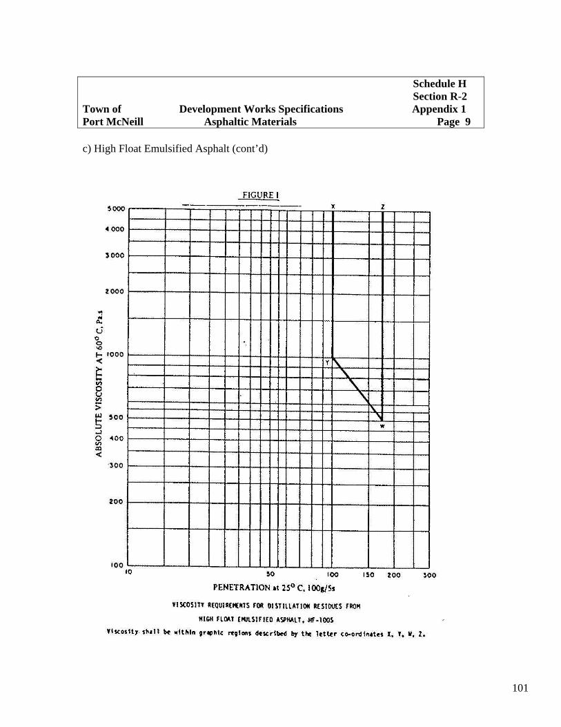
101
c) High Float Emulsified Asphalt (cont’d)
Schedule H Section R-2 Town of Development Works Specifications Appendix 1 Port McNeill Asphaltic Materials Page 9

102
c) High Float Emulsified Asphalt (cont’d)
Schedule H Section R-2 Town of Development Works Specifications Appendix 1 Port McNeill Asphaltic Materials Page 10

103
Schedule H Section R-2 Town of Development Works Specifications Appendix 2 Port McNeill Base and Sub-Base Preparation Page 1
1.0 Scope
1.01 General
This specification describes the materials, equipment and workmanship required for construction of granular surfacing, bases and sub-bases, using crushed granular or pit-run aggregates.
1.02 Description of Work – The aggregates for granular surfacing, bases and sub-bases shall be supplied by the Contractor. All materials shall be from an approved source and shall be free from lumps of clay, silt, decomposed rock, organic or other deleterious matter. Material that is stock-piled prior to use shall be handled in a manner to avoid segregation. Such care shall be used subsequently in hauling to the area of accurately, and thoroughly compacted to the line and grade designated. Surfacing aggregate intended for surface-stabilization to be done in place on the road, shall be placed on the untreated base only as fast as it can be incorporated in the road mixed stabilizer base. Unless otherwise provided in the Special Provisions, the Contractor shall maintain the prepared surface of the untreated surfacing, until it has been treated or covered with stabilized surface material.
2.0 Materials
2.01 Aggregate shall be composed of inert, durable fragments, free from an excess of flat or elongated particles, and uniform in quality. Soundness testing may be requested by the Consulting Engineer in the absence of satisfactory performance records for the aggregates particular source. Such testing shall be in accordance with A.S.T.M. Specification C88, using Magnesium Sulphate. Aggregates so tested, shall be considered satisfactory, if the loss over five (5) cycles does not exceed twenty (20) percent for coarse aggregate or twenty-five (25) percent for fine aggregate.
2.02 Crushed Surfacing, Crushed Pit-Run and Pit Run
a) Crushed surfacing, crushed pit-run and pit run and when tested in accordance with A.S.T.M. Specification C136 shall have a gradation falling within the following limits.

104
Schedule H Section R-2 Town of Development Works Specifications Appendix 2 Port McNeill Base and Sub-Base Preparation Page 2
MATERIAL DESCRIPTION PERCENTAGE PASSING EACH TYPE OF
AGGREGATE
Aggregate size: 20mm 80mm 80mm Type of aggregate: crushed crushed pit-run pit-run Aggregate use: surfacing base course sub-base U.S. Standard CGSB 8 – GP – 2M Sieve Size Sieve Size 3’’ 80mm 100- 100 1 ½’’ 40mm 60-100 ¾’’ 19mm 100 40-80 15-100 3/8 9.5mm 60-100 30-60 0-100 No.4 4.75mm 40-80 20-45 0-100 No.8 2.36mm 30-60 15-35 No.16 1.18mm 20-45 10-25 No.50 300um 8-20 4-16 0-15 No.100 150um No.200 75um 2-9 2-9 0-5
b) Should the Contractor supply aggregate with a gradation coarser than paragraph 2.02a), and can satisfy the Consulting Engineer that the compaction and stability requirements can be met, the Engineer may direct, in writing, that such aggregate may be used.
c) In the crushed material, at least fifty (50) percent by numerical count of all
coarse particles retained on the 4.75 mm sieve shall have at least one fractured face or shall be naturally angular with sharp edges.
3.0 Construction Method
3.01 Weather and Job Conditions
a) No construction shall be undertaken during heavy rain, snow or freezing conditions.

105
Schedule H Section R-2 Town of Development Works Specifications Appendix 2 Port McNeill Base and Sub-Base Preparation Page 3
b) Granular aggregate shall not be placed upon a frozen, wet, muddy or rutted
sub-grade, sub-base, or surface, unless directed by the Engineer, in writing. c) When the sub-grade or base is soft due to excessive moisture conditions,
granular materials shall be hauled and placed, such that no rutting or displacement of lower layers occurs.
3.02 Construction Thickness of Granular Courses
a) Crushed granular surface course, and crushed granular or pit-run base course and sub-base courses shall be constructed to the thickness and dimensions as shown in the Contract Documents or described in the Special Provisions, unless otherwise directed by the Consulting Engineer, in writing.
b) Aggregate shall be delivered to the road bed as uniform mixtures and shall be
spread in layers or windrows without segregation. Granular aggregate shall not be end-dumped from trucks and piles on the road bed.
c) When the sub-grade consists of cohesionless material, the Consulting
Engineer may approve in writing, that granular sub-base or base may be dumped in piles and spread in sufficient quantity to stabilize the sub-grade.
d) Fly spreading from the tailgate of trucks may be permitted by the Consulting
Engineer, provided that the work is well controlled and that no segregation will occur. Any segregation of materials shall be remixed until uniform.
e) Surfacing materials shall only be laid on a dry base and when weather
conditions are suitable, except as directed by the Consulting Engineer.
3.03 Construction of Crushed Granular Base or Pit-Run Sub-Base
a) Where the required thickness is 150 mm or less, the aggregate base or sub-base may be spread and compacted in one layer. Where the required thickness is more than 150 mm, the aggregate shall be spread and compact in two or more layers of equal thickness. The maximum compacted thickness of any one layer shall not exceed 150 mm. Each layer shall be spread and compacted in a similar manner.
b) Following spreading, the materials shall be compacted to 95% of the
laboratory density obtained by the following A.S.T.M. Specification 698,

106
M Method C, or latest revision thereof with exception of the top 300 mm which shall be compacted to 100%.
c) The sub-base or base shall be constructed so that the final surface shall
conform to the Design Drawing for line, grade and cross-section, or as staked by the Consulting Engineer to an accuracy of + 15mm.
3.04 Construction of 20 mm Crushed Granular Surfacing
a) Crushed granular surfacing shall not be spread until the base has been approved by the Consulting Engineer. If the Consulting Engineer is of the opinion that the finished surface of the base does not meet the requirements of paragraph 3.03 c) but has been thoroughly and densely compacted and should not be distributed, he may order that the surface of the base be corrected to true cross-section line and grade, within the specified tolerances, by use of a leveling course of 20 mm granular surfacing aggregate.
b) The surfacing aggregate shall be spread in such a manner that the aggregate
does not segregate. The thickness of the surfacing shall be uniform and the minimum thickness of the constructed surfacing aggregate shall be not less that the nominal thickness shown in Municipal Standard Drawings R1, R2, and R3.
c) Following spreading, the material shall be compacted to one-hundred (100)
percent of the density obtained in the laboratory in accordance with A.S.T.M. Specification D698-Method D.
d) The sub-base or base shall be constructed so that the final surface shall
conform to Municipal Standard Drawings R1, R2, and R3, for line, grade, and cross-section, to an accuracy of + 10 mm.
3.05 Compaction Method and Equipment
a) The compaction and equipment used to obtain the specified density may be
selected by the Contractor, but will be subject to review or alteration by the Consulting Engineer, if the Contractor is unable to attain the desired density.
b) For the purpose of the compaction requirements of paragraphs 3.03 b) and
3.04 c), compaction equipment shall meet the following minimum requirements.
Schedule H Section R-2 Town of Development Works Specifications Appendix 2 Port McNeill Base and Sub-Base Preparation Page 4

107
1. Three wheel steel rollers shall have a loaded mass of not less than 10.9 tonnes, with a compression at the rear wheels of not less than 60.0 N/mm of width.
2. Segmented steel wheel rollers shall have two rolls side by side each of
a minimum width of 750 mm and minimum diameter of 1500 mm. The minimum loaded rolling mass shall be 13.6 tonnes.
3. Vibratory rollers shall have a minimum steel drum diameter of 1150
mm a minimum drum width of 1500 mm and shall be capable of being loaded so as to have a load of 17.5 N/mm of drum width.
4. Pneumatic tired rollers shall be equipped with wheels which carry
13.00 x 24 pneumatic tired capable of being inflated to a minimum pressure of 825 kPa, and shall have a loaded mass such that all wheels carry a minimum proportional load of 31.14 kN.
c) Notwithstanding paragraph 3.05 b), the Consulting Engineer may give
approval for the use of new or alternative compaction equipment, if he is satisfied that such equipment will provide equal or superior compaction performance.
d) Subject to the approval of the Consulting Engineer, base, sub-base and
surfacing aggregates may be watered by the Contractor, as required to aid in attaining the specified density.
3.06 Responsibility for Base
It shall be the Developer’s responsibility to examine the base immediately prior to commencing paving operations and satisfy himself that it is properly prepared to receive the pavement.
3.07 Adjustment of Service Structures
Existing manholes, catch basins, valve boxes and other service structures, within the area to be paved, shall be adjusted to the property finished grade at the time of paving.
Schedule H Section R-2 Town of Development Works Specifications Appendix 2 Port McNeill Base and Sub-Base Preparation Page 5
108
Schedule H Development Works Specifications Section R-2Town of Surface Separation Appendix 3 Port McNeill For Asphalt Paving Page 1
1.0 General
1.01 All contact surfaces that are to receive asphaltic concrete paving shall be prepared as set out in this Specification. Surface preparation may be generally described as being either priming of non-asphaltic granular bases or tack-coating of existing asphaltic pavement, which are to receive an overlying surfacing course.
2.0 Materials
2.01 Prime or tack-coat asphalts shall be those specified by the Municipal Engineering Advisor. The asphalt specified shall conform to Appendix 1 – Asphaltic Materials.
2.02 Primer shall be used at the Engineer’s discretion. Primer shall be applied on the
granular base when the surface is dry or slightly damp and the air temperature above 10º C. The primer shall be uniformly applied with an approved pressure distributor at a rate of 1.0 to 1.5 liters per square meter, and the temperature of the material shall be such that the kinematic viscosity will be between 50 and 150 square millimetres per second.
Primer shall be allowed to cure for a minimum of 4 hours. Traffic shall be kept off
primed areas until the primer has been allowed to cure. Additional primer shall be applied to areas requiring priming to fill voids, to coat and bond particles, or as directed by the Engineer. If the primed surface is loose, rolling of the surface with a pneumatic-tired roller may be required.
2.03 Tack coat shall be applied to all existing asphaltic concrete which is to be overlain,
the edge of curbs, existing asphaltic concrete and structures, where the surface of these structures will in contact with new asphaltic concrete pavement.
3.0 Equipment
3.01 Rotary Power Brooms shall be used for all brooming work. The brooms shall be mounted on self-propelled pneumatic-tired tractor units, and shall be capable of vertical adjustment and shall have sufficient power and brushing capacity to completely clean the surface to be paved within three (3) coverage. Hand brooms shall be used to clean all depressions not reached by the rotary broom.
3.02 Pressure Distributors shall be designed and operated to distribute the asphaltic
material in a uniform spray Schedule H

109
3.03 Pressure Distributors shall be designed and operated to distribute the asphaltic material in a uniform spray without atomization, in the amount and between the limits of temperature specified.
a) They shall be equipped with a bitumeter having a dial registering metres per
minute. The dial shall be visible to the truck driver so he can maintain the constant speed required for application at the specified rate.
b) The pump shall be equipped with a tachometer, having a dial registering litres
per second passing through the nozzles. The dial shall be readily visible to the operator.
c) Means for indicating accurately the temperature of the asphaltic material at all
times shall be provided. The thermometer well shall not be in contact with a heating tube.
d) The normal width of application of the spray bar shall be not less than 3.5m,
with provisions for the application of lesser width when necessary. A hose and spray nozzle attachment shall be provided for applying asphaltic material to patches and areas inaccessible to the spray bar.
e) The distributor shall be provided with eating attachments and the asphaltic
material shall be circulated during the entire heating process.
4.0 Cleaning of Surfaces
4.01 All surfaces, both horizontal and vertical, which will be in contact with the new asphalt mix shall be thoroughly cleaned of all dirt and debris. Cleaning will normally be done using rotary brooms and hand brooms, however, washing of flushing may be necessary to remove coatings of clay or dirt on old pavement.
5.0 Preparation of Vertical Surfaces
5.01 Vertical faces of existing pavements, curbs, gutters, drainage gratings, manholes, or other contact surfaces shall be sprayed or painted with a uniform coating of hot asphalt or asphalt emulsion. Sufficient material shall be used to provide closely bonded water-tight joints. This work shall be done in such a way as to not stain exposed curb or gutter surfaces.
Development Works Specifications Section R-2 Town of Surface Separation Appendix 3 Port McNeill For Asphalt Paving Page 2

110
6.0 Priming Non-Asphalt Base
6.01 Prior to priming, the granular base, unless constructed by the paving contractor immediately prior to paving, shall be prepared by blading, dragging, spraying with water and compacting with rollers as required, so as to provide a uniform tight compacted surface, correct to line, grade, and crown or superelevation. All surplus loose aggregate shall be bladed clear on the shoulders for use in shouldering. Care shall be exercised in removing loose aggregate, to guard disturbing the bond of the aggregate in the surface of the base.
6.02 Asphaltic priming shall take place when the granular base is dry or slightly damp and
the ambient temperatures are over 10º C. 6.03 The selected asphaltic primer shall be uniformly sprayed by an approved distributor at
the rate specified by the Consultant Engineer. 6.04 The primer shall be sprayed within a temperature range which will cause the
kinematic viscosity to be between fifty (50) and one hundred and fifty (150) centistokes.
6.05 Care shall be exercised, however, to prevent over priming. Prime that is not absorbed
into the base within twenty-four (24) hours after application, or over-priming, shall be corrected by the application of selected cover sand.
6.06 Any spraying faults shall be corrected by hand spraying, brooming or the subsequent
removal of cover sand placed on over-primed areas. The asphaltic primer shall be entirely absorbed by the base course.
6.07 All traffic, where possible, shall be kept off the prime base until the primer has been
absorbed. Where it is not possible to keep traffic off wet primer, the surface shall be blinded with a cover sand or fine aggregate.
6.08 The Contractor shall maintain the base as may be necessary to keep the surface prime
intact.
7.0 Tack Coating of Existing Asphaltic Pavements
7.01 Prior to tack coating, deficiencies in the existing pavement shall be treated as follows:
Schedule H Development Works Specifications Section R-2 Town of Surface Separation Appendix 3 Port McNeill For Asphalt Paving Page 3

111
a) Joints and cracks, 15mm or more in width, should have the existing filler removed to a depth of at least 25 mm. They shall be refilled with a dense, fine-graded mixture thoroughly tamped into place. Any excess shall be removed level with the pavement surface.
b) Rigid-type pavements that have transverse pre-molded expansion and
longitudinal joints shall be cleaned out to a depth of 50 mm and refilled as noted in paragraph 7.01 a).
c) Asphaltic patches which appear to contain an excess of asphalt or may appear
to be unstable shall be removed from the pavement. d) Surface cracks wider than 5 mm shall be treated as in paragraph 7.01 a). e) Surface cracks less than 5 mm in width shall be treated with the same
asphaltic material as used in the tack coat.
7.02 After all repairs have been completed, the surface shall be cleaned as noted in paragraph 4.01 immediately prior to application of the tack coat.
7.03 Tack coating shall take place when the ambient temperature is over 10º C. 7.04 The selected asphaltic tack coat shall be uniformly sprayed by an approved distributor
at the rate specified by the Consulting Engineer. 7.05 Extreme care shall be exercised in the application of the tack coat so as to avoid a
surplus of asphalt which may flush into the overlying course. 7.06 In places where the distributor bars cannot reach, the tack coat shall be applied with a
hand sprayer attached to the distributor by a hose. When hand spray methods are use, care shall be taken to avoid over-coating of the surface.
7.07 Nor more tack coat than is necessary for the day’s operation shall be places on the
surface. All traffic not essential to the work shall be kept off the tack coat.
Schedule H Development Works Specifications Section R-2 Town of Surface Separation Appendix 3 Port McNeill For Asphalt Paving Page 5

112
Schedule H Section R-2 Town of Development Works Specifications Appendix 4Port McNeill Asphaltic Concrete Paving Page 1
1.0 Scope
1.01 General
a) This Specification describes the materials, plant equipment and workmanship required for the construction of hot mixed, hot laid asphaltic concrete pavement.
b) This Specification shall be read and construed with the Special Provisions of
the Contract, as prepared by the Consulting Engineer, and the approved Design Drawings.
1.02 Description of Work Under this Specification, asphaltic concrete consisting of mineral aggregate and
asphaltic binder, shall be combined and hot mixed in an approved mixing plant, spread on a prepared base and compacted to an approved density, all as shall be described in this Specification.
1.03 Pavement Types and Design Criteria
a) There shall be three (3) types of mixes for pavement construction:
1) Coarse Mix, for base and surface courses where specified. 2) Medium Mix, which shall be the normal mix for pavement
construction. 3) Fine Mix, for light surface courses and special levelling purposes.
b) There shall also be three (3) strength classifications for asphaltic concrete pavement, based on design traffic criteria in accordance with the Asphalt Institute Specification Series No. 9 (SS-1) Manual:
Class A – Light Traffic Classification – Residential Road/ Class B – Medium Traffic Classification – Collector Road. Class C Heavy Traffic Classification – Major Road
Mixes for each class of pavement shall meet Marshall Test design criteria as specified in the following table. c) The type and class of pavement required shall be specified by the Municipal
Engineering Advisor.

113
PROPERTY OF LABORATORY COMPACTED PAVING MIXTURE PAVEMENT CLASS A B C Number of flows each face of test specimen 35 50 75 Stability, all mixtures, N. 2250 2250 3350 Flow index, all mixtures, units of 0.25 mm 8-20 8-18 8-16 Percent Air Voids Surface or levelling course 3-5 3-5 3-5 Base course 3-8 3-8 3-8 Minimum Percent Voids in Mineral Aggregate for nominal maximum particle size 20 mm 14 14 14 15 mm 15 15 15 10 mm 16 16 16 Minimum index of retained stability after immersion in water at 60º C for 24 hours. 80% 80% 80%
d) Mixes shall be designated as to mix type number followed by class strength classification. Thus, coarse mixes will be designated as Mix 1A, Mix1B, and Mix 1C. Medium mixes will be designated as Mix 2A, Mix19, and Mix 2C. Fine mixes will be designated as Mix 3A, Mix 3B, and Mix 3C.
1.04 Final compaction Requirements
a) If required by the Municipal Engineering Advisor, cores will be drilled from the road surface after final rolling is completed. The cores shall be used to measure thickness of the pavement and to test the density of the compacted mix, as required under paragraph 1.04 b).
b) The compacted asphalt concrete pavement shall have a density equal to or
greater than ninety-seven (97) percent of a laboratory specimen prepared by the Marshall Test Method in accordance with paragraph 1.03 b), from a sample taken from a truck delivering the mixture on the job site. The laboratory density shall be compared with the filed density at the location of the same truckload mixture from which the laboratory specimen was made.
c) The compacted base and surface course shall have average thickness no less
than that specified by the approved Design Drawings. Any deficiency in base course thickness shall be made up with surface mixtures when the surface course is placed.
Schedule H Section R-2 Town of Development Works Specifications Appendix 4 Port McNeill Asphaltic Concrete Paving Page 2

114
2.0 Materials
2.01 Methods of Test
a) Asphaltic materials shall be tested in accordance with methods of test designated on Appendix 7 – Methods of Test.
b) Mineral aggregates shall be tested in accordance with methods of test
designated in Appendix 7 – Methods of Test.
2.02 Asphaltic Material
a) Asphaltic cement to be used in preparation of asphaltic concrete paving mixtures shall be penetrating asphalt as described under Appendix 1 – Asphaltic Materials and of the grade specified in the Special Provisions. Such material shall at no time be heated to a temperature in excess of that which will cause the material to have a kinematic viscosity of less than one-hundred (100) centistokes.
b) The bituminous cement content of the mix as determined by the Consulting
Engineer shall not vary from the selected job mix content by more than 0.3 percent by mass of the total mix.
2.03 Coarse Aggregate
a) For purpose of standard A.S.T.M. tests, coarse aggregate shall be all mineral material retained on the 4.75 mm sieve. It shall consist of stone, crushed slag, crushed gravel or combinations thereof, or materials naturally occurring in a fractured condition or of a highly angular natural aggregate with pitted or rough surface texture.
b) The coarse aggregate other than slag or naturally occurring rough textured or
pitted surface aggregate shall contain at least sixty (60) percent by mass of crushed pieces having two (2) or more surfaces or faces produced by fracture, when the aggregate is required for incorporation in mixes to be used in construction of pavements, types B or C.
c) Aggregate having known polishing characteristics shall not be used in surface
coarse mixes except by express permission of the Municipal Engineering Advisor.
Schedule H Section R-2 Town of Development Works Specifications Appendix 4 Port McNeill Asphaltic Concrete Paving Page 2

115
d) The maximum absorption of the coarse aggregate when tested in accordance
with A.S.T.M. Designation C127 shall be 1.7 percent. e) All coarse aggregate shall be free from coatings of clay, silt, or other
objectionable matter and shall not contain more than 1.5 percent by mass of clay balls or other aggregations of fine material.
f) Coarse aggregate shall be tested for soundness in accordance with A.S.T.M.
Specification C88 for which maximum weighted losses for five (5) cycles shall be eighteen (18) percent when magnesium sulphate is used.
g) Crushed slag shall meet the requirements of A.S.T.M. Specification D693.
2.04 Fine Aggregate
a) For purposes of standard A.S.T.M. test, fine aggregate shall be allmineral matter passing the 4.75 mm sieve including mineral fillers. It shall consist of natural and/or manufactured material derived by crushed stone, slag, or gravel.
b) The aggregate particles shall be clean tough, durable, moderately sharp and
free from coating of clay, silt, or other objectionable matter, and shall contain no clay balls or other aggregations of fine material.
c) Fine aggregate shall be tested for soundness by A.S.T.M. Specification C88
for which maximum weighted losses for five (5) cycles shall be twenty (20) percent when magnesium sulphate is used.
2.05 Mineral Filler
a) Mineral filler shall consist of all mineral matter which will pass No. 200 sieve. b) Mineral filler pay consist of fine particles of the coarse or fine aggregate or of
finely ground particles of limestone, hydrated lime, Portland Cement, or other selected mineral matter. It shall be dry, free from organic matter, clay particles or lumps.
c) Mineral filler shall be non-plastic when tested by A.S.T.M. Specification D-
423 and D-424.
Schedule H Section R-2 Town of Development Works Specifications Appendix 4 Port McNeill Asphaltic Concrete Paving Page 3

116
2.06 Paving Mixes
a) paving mixes prepared under these specifications shall be composed of aggregates and paving asphalt meeting the requirements of the following table:
J.S Standard CGSB B-GP-2M Percentage Passing for Each Mix Type Sieve Size Sieve Size Coarse Medium Fine ¾’’ 19 mm 100 ½’’ 13.2 mm 80-100 100 3/8’’ 9.5 mm 70-90 80-100 100 No. 4 4.75 mm 50-70 55-75 80-100 No. 8 2.36 mm 35-54 35-57 54-39 No.16 1.13 mm 25-12 25-44 48-75 No.30 600 mm 18-32 18-32 32-50 No.50 300 mm 13-24 18-23 15-42 No.100 150 mm 8-15 8-16 5-23 No.200 75 mm 2-3 4-10 4-10
b) However, should the Contractor provide an aggregate which will meet the overall maximum size and design requirements of paragraph 1.03, other than Index of Retained Stability After Immersion in Water, such aggregate may be accepted upon approval of the Consulting Engineer, notwithstanding the fact that its grading curve does not fall within the limits prescribed in the above table.
c) If sieve test results indicate that variations in aggregate gradation are
exceeding the maximum permissible limits detailed above, the Contractor shall immediately modify his aggregate production procedure to the satisfaction of the Consulting Engineer so as to produce aggregate having a gradation which will consistently fall within the permissible limits specified. Aggregate produced during periods when gradation is out of control may be rejected by the Consulting Engineer and shall be removed or otherwise disposed of as may be directed.
Schedule H Section R-2 Town of Development Works Specifications Appendix 4 Port McNeill Asphaltic Concrete Paving Page 4
117
3.0 Plant and Equipment
3.01 Paving Plant Essentials
a) The plant used by the Contractor for the preparation of hot mix asphaltic concrete material shall conform to the requirements for mixing plants for hot mix, hot-laid bituminous paving mixtures, A.S.T.M. Specification D9995 and to the recommended procedures of the Asphalt Institute’s “Asphalt Plant Manual” Manual Series No.3 (MS-3).
b) The plant shall be so designed and co-ordinated as to produce a uniform
mixture within the Specifications.
3.02 Control of Mixing Temperatures
a) The mixing temperature for a particular asphaltic concrete mix shall be that which corresponds to a viscosity range of 150 to 300 centistokes (75 to 150 seconds Saybolt Furol) for the asphalt cement penetration grade specified in the Special Provision. Mixing temperatures generally shall conform to the recommended temperatures of the Asphalt Institute. At no time shall the maximum mixing temperature exceed 175º C. The lowest possible temperature consistent with paragraph 3.02 b) should be used.
b) Mixing temperature shall be consistent with paragraph 3.03 to provide
uniform coating of asphalt on all aggregate particles.
3.03 Control of Mixing Time
Mixing time shall be the minimum required to obtain a uniform distribution of aggregate sizes and a uniform coating of asphalt on all aggregate particles. The minimum mixing time shall be that which produces a Ross Count of:
1. 90 percent fully coated for base mixes 2. 95 percent fully coated for surface mixes
as determined by the Ross Count Procedure. The least time needed for the pugmill to produce mixes meeting the minimum coating requirements shall be the minimum mixing time.
Schedule H Section R-2 Town of Development Works Specifications Appendix 4 Port McNeill Asphaltic Concrete Paving Page 5

118
3.04 Transporting the Mixture
a) Trucks used to haul the asphalt paving mixture from the plant to the job site shall be in good mechanical condition at all times. Truck bodies that come in contact with the asphalt mixture should be clean and smooth and free from cracks, holes, dents, and shall be clean of all foreign material.
b) Surfaces of the truck coming in contact with the asphalt paving mixture may
be lubricated with either a mild lime water, a soap or detergent solution, or an approved commercial solvent in emulsion form suitably diluted as recommended by the manufacturer. After the solution has been painted or sprayed on, the truck beds should be elevated so the excess can drain out. Oil, grease and other similar products shall not be permitted.
c) A canvas or similar covering shall be used to cover the hot mix after loading
into the truck regardless of the ambient temperature or haul distance. Hauling trucks in which frame-contact or bed-bearing with the pavers during dumping operation shall not be used.
d) Any load with a paving mix temperature of less than 120º C will be rejected.
The lowest acceptable mix temperature may only be varied upon the approval of the Consulting Engineer.
e) No load shall be sent out so late in the day as to interfere with spreading and
compacting the mixture during daylight unless artificial light, satisfactory to the Consulting Engineer, is provided.
4.0 Asphaltic Concrete paving
4.01 Base preparation
No asphalt paving mixture shall be placed on a base that has not been either primed or tack-coated in accordance with the Specifications and in accordance Appendix 3 - Surface Preparation for Asphaltic paving.
Schedule H Section R-2 Town of Development Works Specifications Appendix 4 Port McNeill Asphaltic Concrete Paving Page 6

119
4.02 Paving Equipment
a) Unless otherwise specified, all plant-mixed bituminous mixtures shall be spread by means of mechanical self-powered pavers capable of spreading the mix true to the line, grade and crown indicated on the approved Design Drawing.
b) At the forward end of the machine there shall be hoppers of sufficient capacity
to enable the pavers to spread the paving mixture continuously and without interruption during the dumping cycle of the haulage trucks. The pacing mixture shall be transformed from the hoppers to reserving type distributing screws, design to distribute the paving mixture evenly and without segregation, across the full laying with paver screeds.
c) The paver shall be equipped with an activated screed which shall be adjustable
as to level and section. A dampened dial level shall be fitted to the machine so that proper pavement crown or cross fall can be produced throughout the finishing operation.
d) The paver shall be fitted with mechanical devices suck as equalizing or
straight edge runner, or evener arms or such other compensating devices to prevent minor change in the sub grade elevation from being reflected in the finished surface.
4.03 Placing the Mixture
a) Asphalt paving mixture shall only be laid upon a base, and under weather conditions, approved by the Consulting Engineer. The surface of the base shall be dry. Prior to delivery of the mixture, the prepared base shall be cleaned of all loose or foreign material.
b) Asphalt paving mixture shall only be laid when the ambient temperature is
above 5º C and rising. c) The mixture shall be spread and tamped to the necessary thickness. The paver
feed shall be so adjusted to the rate of delivery of the asphaltic mixture, that the paver shall spread mixture at a constant speed and with a minimum of stoppages.
Schedule H Section R-2 Town of Development Works Specifications Appendix 4 Port McNeill Asphaltic Concrete Paving Page 7

120
d) The paving mixture shall be spread at the lowest speed compatible with the
rate of supply of the paving mixture. The road speed of the paver shall not exceed ten (10) meters per minute for base course mixtures or eight (8) meters per minute for surface course mixtures without the express permission of the Consulting Engineer.
e) Following screeding and prior to roller compaction, the surface shall be
checked and any irregularities such as fatty accumulations or other non-uniform surface texture shall be adjusted. Crooked edges on the paving mat shall be straightened by either removing and wasting mix which bows outside the edge of the mat is indented, before the edge is rolled.
f) In places inaccessible to paving machine, hand spreading will be permitted.
Placing and spreading by hand shall be done very carefully and the material distributed uniformly so that segregation of the coarse aggregate and asphaltic mortar will be avoided. The asphaltic mix shall be distributed into place using hot shovels shall be spread with hot rakes in a loose layer of uniform density and correct depth. Asphaltic paving mixture for hand spreading shall not be dumped any faster than can be handled by shoveling and raking.
4.04 Joints
Longitudinal and transverse joints shall be carefully prepared, bonded and sealed. a) Transverse Joints in both base and surface courses shall be carefully constructed
and thoroughly compacted to provide smoothness and true alignment. If a bulkhead was not used to form a transverse join, the line of the joint shall be located a sufficient distance back of the rounded edge, to provide a true surface and cross section. Where material is trimmed, a neat and vertical face shall be prepared and this face shall be sprayed or painted with a thin uniform coat of hot asphalt cement, or other asphaltic bonding material as may be directed by the Consulting Engineer.
Schedule H Section R-2 Town of Development Works Specifications Appendix 4 Port McNeill Asphaltic Concrete Paving Page 8

121
Schedule H Section R-2 Town of Development Works Specifications Appendix 4 Port McNeill Asphaltic Concrete Paving Page 9
b) Transverse joints made next to an adjoining lane shall be rolled initially by
making a pass along the longitudinal joint for a few metres. The surface shall be checked with a straight-edge and corrections made if necessary. The joint shall then be rolled except for a 150 mm projection of the wheels on the freshly laid material. This procedure shall be repeated with successive passes each covering 150 to 200 mm of fresh material until the entire width of a drive roll is on the new mix. Boards of proper thickness should be placed at the edge of the pavement to provide for off-pavement movement of the roller. Where this is impractical, transverse rolling shall stop 150 to 200 mm short of the outside edge of the pavement, and the outside edge shall be rolled out during longitudinal rolling.
c) Longitudinal Joints shall be planned to provide an offset of at least 150 mm
from like joints in a previously laid course. The first lane placed shall be true to line and grade and have a near vertical face. Before compaction, the material along unsupported edges shall be butted and slightly elevated with a tamping tool or pavement shall be trimmed to provide a vertical face and this face shall be sprayed or painted with a thin uniform coat of hot asphalt cement, or other asphaltic bonding material as may be directed by the Consulting Engineer.
d) When paving is done against an abutting lane, the paver shall be positioned so
that in spreading, the new mix overlaps the compacted lane of pavement by no more than 75 mm. Coarse aggregate in the material overlapping the cold joint shall be carefully removed and wasted. If another course is to be placed over the course being spread, the excess coarse aggregate may be spread over the unrolled lane with a broom or lute. When placing a surface course excess coarse aggregate shall not be spread over the freshly laid mat.
e) Longitudinal joints shall be rolled directly behind the paving operation.
Rolling of joints shall be done with the roller wheels positioned on the previously laid pavement so not more that 150 mm of the rear roller wheel rides on the freshly laid mix. The roller shall continue to roll this line, gradually shifting its position across the joint, until a thoroughly compacted and neat joint is obtained.

122
Schedule H Section R-2 Town of Development Works Specifications Appendix 4 Port McNeill Asphaltic Concrete Paving Page 10
5.0 Compaction
5.01 General
Compaction of freshly laid asphaltic concrete shall be such that the final compaction requirements of paragraph 1.04 are satisfied and that the finished pavement shall be smooth and accurate to the established grade and crown.
5.02 Surface
The surface of the finished pavement shall be free from objectionable paver ripple and from lumps or depressions exceeding 5 mm from a 3 m straight edge laid thereon parallel to the center line of a camber board laid transversely.
5.03 Compaction Method and Equipment
a) The method of compaction to obtain the specified density, may be selected by the Contractor, but shall be subject to approval by the Consulting Engineer. The equipment should meet the following minimum requirements.
1. Three wheel steel rollers shall have a loaded weight of not less than 10.9
tones, with a compression at the rear wheels of not less than 60 N/mm of width.
2. Steel wheel or segmented steel wheel rollers shall have two rolls side by side
each of a minimum width of 750 mm and minimum diameter of 1500 mm. The minimum loading rolling mass shall be 13.6 tonnes.
3. Vibration rollers shall have a minimum steel drum diameter of 1150 mm, a
minimum drum width of 1500 mm and shall be capable of being loaded so as to have a loaded mass of 17.5/mm of drum width.
4. Pneumatic tired rollers shall be equipped with wheels which carry 13.00 x 24
pneumatic tires capable of being inflated to a minimum pressure of 825 KPa and shall have a loaded mass such that all wheels carry a minimum proportional load of 31 kN.

123
Schedule H Section R-2 Town of Development Works Specifications Appendix 4 Port McNeill Asphaltic Concrete Paving Page 11
b) For pneumatic tired rollers, tire contact pressures shall be as high as possible
without causing displacement of the mix that cannot be remedied in the final rolling. The use of small amount of non-foaming detergent or water-soluble oils on the wetting mat of the pneumatic tired rollers at the beginning of the rolling operation will be most helpful in preventing the asphalt from sticking to the tires until they warm up.
c) During rolling, the roller wheels should be kept moist with only enough water
to avoid picking up the material. Rollers should move at a slow but uniform speed with the drive roll or wheels nearest the paver. The speed should not exceed 5 km/h for steel wheeled rollers, or 8km/h for pneumatic-tired rollers. Rollers should be in good condition, capable of being reversed without backlash. The line of rolling should not be suddenly changed or the direction of rolling reversed, thereby displacing the mix. Any pronounced change in direction of the roller should be made on stable material, the affected areas should be loosened at once with lutes or rakes and restored to the original grade with loose material before being re-rolled. Heavy equipment, including rollers, should not be permitted to stand on the finished surface before it has thoroughly cooled or set.
5.04 Rolling Procedure
a) When paving in single width, the first lane placed shall be rolled in the following order:
1. Transverse joints. 2. Outside edge. 3. Initial or breakdown rolling, beginning on the low side and
progressing toward the high side. 4. Second rolling, same procedure as 3. 6. Finish rolling.
b) When paving in echelon, or abutting a previously placed lane, the mix shall be rolled in the following order:
1. Transverse joints 2. Longitudinal joints. 3. Outside edge.

124
Schedule H Section R-2 Town of Development Works Specifications Appendix 4 Port McNeill Asphaltic Concrete Paving Page 12
4. Initial or breakdown rolling, beginning on the low side and
progressing toward to high side. 5. Second rolling, same procedure as 4. 6. Finish rolling.
c) When paving in echelon, 50 to 75 mm of the edge which the second paver is
following shall be left unrolled, and rolled when the join between the lanes is rolled. Edges shall not be exposed more than fifteen (15) minutes without being rolled. Particular attention shall be given to the construction of transverse and longitudinal joints in both intermediate and surface courses.
5.05 Breakdown Rolling
a) Breakdown rolling shall be accomplished with steel wheel rollers or approved pneumatic rollers. Breakdown rollers shall work as closely as possible behind the paving machine, without cracking the mat or having the mix pick up on the roller wheels.
b) Breakdown rolling shall start on the low side of the spread, which is normally
the outside of the lane being paved, and progress toward the high side. When adjoining lanes are placed, the same rolling procedure shall be followed but only after compacting of the fresh mix at the longitudinal joint with 150 to 200 mm of the roller width.
c) A pattern of rolling that will provide the most uniform coverage of the lane
being paved shall be used. Normally, this pattern will involve overlapping on successive trips by at least one half the width of the narrowest wheel of the roller.
d) Breakdown rollers shall generally move onto the freshly laid mat with the
drive rolls forward in the direction of paving.
5.06 Intermediate Rolling
a) Intermediate rolling shall follow the breakdown rolling as closely as possible while the asphalt mix is still plastic and at a temperature that will result in maximum density.

125
Schedule H Section R-2 Town of Development Works Specifications Appendix 4 Port McNeill Asphaltic Concrete Paving Page 13
b) Normally, pneumatic tired rollers shall be used for the intermediate rollings.
Pneumatic tired rollers shall be continuous, consisting of at least three (3) complete coverages.
c) Intermediate rolling shall follow the same rolling pattern as used for the
breakdown rolling, and shall be continued until the desired compaction is obtained.
5.07 Finish Rolling
Finish rolling shall be accomplished with two-axle tandems while the material is still warm enough for removal of roller marks.
5.08 Correction of Surface Irregularities
If any irregularities or defects remain after compacting is completed, they shall be corrected in lower courses by removing or adding material. In the surface course the entire affected area of the surface shall be removed promptly and sufficient new material placed to form a true and even surface. All minor surface projections, joints, and minor honey-combed areas shall be rolled to a smooth surface. The final surface shall be of a uniform texture conforming to the line and grade as shown on the Design Drawing. a) For situations where there is evidence of deficient asphalt pavement, a
Certified Materials Testing Laboratory will be engaged by the developer to perform additional tests as required to make recommendations for remedial work which will be approved by the Municipal Engineering Advisor. All remedial work will be completed prior to acceptance of the road works.
5.09 Areas Inaccessible to Rollers
When the asphalt mix is spread in areas that are inaccessible to the rollers, compaction shall be obtained by hand tampers, mechanical tampers, or small vibrating-plate compactors.
5.10 Paving to Existing Curb and Gutter
When asphalt paving is being constructed against existing concrete curb and gutter, the finished surface of the asphalt pavement shall not be less than 5 mm above the top of the gutter.

126
5.11 Traffic Control
No traffic shall be permitted on the finished pavement until it has cooled to such temperature as to ensure that no deformation of the surface will occur.
6.0 Levelling Courses
6.01 Asphalt Mix
Asphalt concrete mixes to be used in placing leveling courses, or the placing of levelling wedges to correct sags and depressions shall be Class C.
6.02 Base Preparation Leveling courses or leveling wedges shall not placed on a base that has not been either primed or tack-coated in accordance with the Special Provisions of the Contract, and in accordance with Appendix 3 Surface Preparation for Asphalt Paving.
6.03 Equipment
a) Self-propelled paving machines may be used. Where construction allows, a long ski riding on an adjacent lane, curb or gutter shall be used. A short ski or shoe grade follower shall be used in instances where a guide-line string is used as a grade reference. A grade reference string line shall be set by the Consulting Engineer to grade references elevation and shall be established parallel to the centre line of the road.
b) Motor graders may be used in laying levelling courses, or levelling wedges
using only very skilled and experienced operators. When spreading levelling courses with a motor grader, such spreading shall be done to establish grade reference points as set by the Consulting Engineer.
6.04 Construction
a) In placing the mix in a levelling course with a motor grader it is essential to place the required amount of mix in each station of the work so that there will not be a large excess of material to waste.
b) The asphalt mixture shall be placed in a conventional trapezoidal windrow
which shall then be spread by the motor grader in the normal fashion.
Schedule H Section R-2 Town of Development Works Specifications Appendix 4 Port McNeill Asphaltic Concrete Paving Page 14

127
c) Ultimately, the asphalt mixture shall be spread from a windrow box to provide a flat spread 100 mm high and from 2 m to 2.5 m wide. The motor grader operator shall then “square blade” the mixture ahead.
d) When an automatic blade control is available on a motor grader, the blade
shall be set to the required transverse slope and string line used to maintain longitudinal alignment.
e) Compaction of the asphalt mixture in levelling courses shall be done with a
pneumatic tired roller following immediately behind the motor grader or paving machine.
6.05 Levelling Wedges
a) Levelling wedges shall be used to level sags or depressions in an old pavement prior to re-surfacing. Levelling wedges shall be placed in layers of not more than 75 mm in thickness. Where thicker wedges are required, multiple layers shall be used.
b) Where multiple layers are required, the Consulting Engineer shall establish
sufficient levels to enable cross-section and profile to be established. c) In placing multiple layers, the shortest length layer shall be placed first with
the successive layer or layers extending over and covering the shortest layer.
6.06 Construction
The method of construction and compaction shall be the same generally as the specified in paragraph 6.04 and following procedural requirements of paragraph 6.05.
Schedule H Section R-2 Town of Development Works Specifications Appendix 4 Port McNeill Asphaltic Concrete Paving Page 15

128
Schedule H Section R-2 Town of Development Works Specifications Appendix 5Port McNeill Surface Treatments Page 1
1.0 Scope
1.01 General
This Specification covers the materials, plant equipment and workmanship required for surface treatments of existing roads.
1.02 Description of Work
Surface treatments usually described as Seal Coats shall be referred to in this Specification as one of the following: a) Aggregate Seal – single or multiple treatments b) Sand Seal c) Fog Seal d) Slurry Seal Additionally, Mixed-in-Place Surface Treatment and Plant-Mixed Surface Treatments shall be described under that particular application.
2.0 Materials
2.01 Methods of Test
a) Asphaltic materials shall be tested in accordance with methods of test designated in Appendix 7 – Methods of Test.
b) Mineral aggregates shall be tested in accordance with methods of test designated in Appendix 7 – Methods of Test.
2.02 Asphalt Primer
The asphalt primer shall be that specified by the Consulting Engineer. The asphalt specified shall conform to Appendix 1 – Asphaltic Materials.
2.03 Asphalt Binder
The asphalt binder shall be that specified by the Consulting Engineer. The asphalt specified shall conform to Appendix 1 – Asphaltic Materials.

129
2.04 Aggregates
a) For aggregate seals, the aggregate shall consist of clean crushed rock or gravel of uniform quality throughout. The aggregate shall have a percent wear by the Los Angeles Abrasion Machine Test of not more than forty, and not less than sixty percent by mass of crushed gravel shall have two or more faces produced by fracture.
b) The aggregate shall meet the following gradation requirements:
Size Nominal
Size Amounts finer than each laboratory sieve (square openings), percentage by weight
Number Square Openings
23.75 mm 19.00 mm 13.20 mm 4.75 mm 2.36 mm 1.18 mm 300 mm
5 19.0 mm to 9.5 mm
100 90 to 100 20 to 55 0 to 15 0 to 5
7 13.2 mm to 4.75 mm
100 90 to 100 40 to 70 0 to 15 0 to 5
8 9.5 mm to 2.36 mm
100 80 to 100 10 to 30 0 to 10 0 to 5
9 4.74 mm to 1.18 mm
100 85 to 100 10 to 40 0 to 10 0 to 5
Numbered sieves are those of the United States Standard Sieve Series, converted to metric by Canadian Government Specification Board Standard 8 – GP – 2M.
Or shall meet the following gradation requirements for one-sized aggregate.
GRADATION REQUIREMENTS FOR ONE SIZE AGGRETATES Size Amounts finer than each laboratory sieve (square openings), percentage by weight. Designation Nominal
Size
Square Openings
23.75 mm 19.00 mm 13.20 mm 9.50 mm 4.75 mm 2.35 mm 75 mm
A 19.0 mm to 13.2 mm
100 85 to 100 2 to 20 0 to 7 0 to 1 0 to 0.5
B 14.25 mm to 9.5 mm
100 85 to 100 0 to 30 0 to 1 0 to 0.5
C 9.5 mm to 4.75 mm
100 85 to 100 0 to 10 0 to 1 0 to 0.5
Numbered sieves are those of the United States Standard Series, converted to metric by Canadian Government Specification Board Standard 8-GP-2M.
c) For sand and seal slurry seals, the aggregate shall consist of clean, sharp sand and
mineral filler, combined to meet the following gradation requirements :
Schedule H Section R-2 Town of Development Works Specifications Appendix 5 Port McNeill Surface Treatments Page 2

130
CGSB 8-GP-2M Sieve Size Total Percent Passing 2.36mm 100 1.18mm 55 – 85 600mm 35 – 80 300mm 20 – 45 150mm 10 – 30 75mm 5 – 15
d) Notwithstanding paragraphs b) and c), should the Contractor provide aggregates which meet the maximum size requirements, and such aggregates have a proven record of service and durability, the Consulting Engineer may approve the use of such aggregates in writing, although they do not meet the overall grading requirements specified.
3.0 Rates of Application
3.01 Rates of application or spread for asphaltic materials and the grade to be used shall be specified by the Consulting Engineer.
3.02 Rates of application or spread for aggregates and the gradation requirements to be
used shall be specified by the Consulting Engineer. 3.03 Surface preparation of Granular Base – Prior to surface treatment of granular bases,
the base shall be prepared in accordance with Appendix 3 – Surface Preparation of Asphalt Paving, paragraph 6.0.
3.04 Surface Preparation of Existing Asphalt Surfaces – Prior to surface treatment of
existing asphalt surfaces, defects in the existing pavement shall be repaired in accordance with Appendix 3 – Surface Preparation for Asphalt Paving, paragraph 7.0.
4.0 Construction Methods
4.01 Construction of Aggregate Seals
a) Subsequent to preparation under paragraph 3.0, the surface to be treated shall be swept clean using a rotary broom, and if dusty, the surface shall be dampened with water. Particular care shall be taken to thoroughly clean the
Schedule H Section R-2 Town of Development Works Specifications Appendix 5 Port McNeill Surface Treatments Page 2
131
outside edges of the area to be treated, and care taken that material removed shall not be mixed with the cover aggregate.
b) Asphaltic primer where specified shall be applied in accordance with
Appendix 3 – Surface Preparation for Asphalt Paving, paragraph 5.0. c) Following absorption and curing of the primer, application of the asphaltic
binder shall be made uniformly at the specified rate using a pressure distributor. The binder shall be applied at a temperature such that the asphaltic viscosity is within the range of twenty to one hundred and twenty centistokes for asphalt cements and liquid asphalts, or fifty to one hundred centistokes for emulsified asphalts.
d) The distributor shall be cleaned thoroughly before using unless its last use was
with the same type of asphaltic binder specified for the work. e) Applications of liquid asphalts (other than emulsified asphalts) and asphaltic
cement shall be made only when the surface is thoroughly dry. Application of emulsified asphalt shall be made when the surface is dry or slightly damp.
f) Asphaltic binder (other than emulsified asphalt RS-2K) shall be applied only
when the pavement temperature is twenty-six (26) degrees Celsius or higher. Emulsified asphalt RS-2K shall be applied only when the pavement temperature is ten (10 degrees Celsius or higher.
g) Before beginning application, building paper shall be spread over the surface,
from the joint back, for a sufficient distance for the spray bar to begin spraying and be operating at full force when the asphalt surface to be treated is reached. The paper shall be removed after application of the asphalt.
h) The spray bar shall be shut off instantaneously at each construction joint to
assure full application of the asphaltic binder up to the joint. Dripping shall be prevented by the insertion of a drip pan under the nozzles.
i) Areas missed by the distributor, shall be touched up with a hand sprayer.
4.02 Application of Aggregate
a) Clean, dry aggregate shall be distributed uniformly by a mechanical or a self-propelled spreader and shall follow immediately the asphaltic application.
Schedule H Section R-2 Town of Development Works Specifications Appendix 5 Port McNeill Surface Treatments Page 3

132
Schedule H Section R-2 Town of Development Works Specifications Appendix 5 Port McNeill Surface Treatments Page 4
b) The cover coat shall be applied ahead of the truck or spreader wheels. c) Immediately after spreading, the aggregate shall be rolled with a self-
propelled pneumatic-tired roller having a total compacting width of not less than 1500 mm and minimum contact pressures of 275 kPa.
d) Rolling shall proceed in a longitudinal direction, beginning at the outer edges
of the treatment and working towards the center, with each trip overlapping the previous trip by one half the width of the front wheels, or roller.
e) The first rolling of the aggregate shall be completed within one half hour after
it has been spread, and rolling shall continue only until a smooth, thoroughly compacted surface is obtained.
f) In instances where the surface treatment is done one-half width at a time, 150
mm of the inside edge shall be left uncovered with aggregate to allow for an overlap of asphaltic binder when the remaining half of the surface is treated.
g) All loose aggregate shall be removed from the pavement following
completion of the work.
4.03 Traffic Control
a) Traffic shall be kept off of freshly sprayed asphalt and shall be directed through the project with the least interruption of the work.
b) Should it be necessary to route traffic over the new treatment, speed shall be
restricted to 8 km/h until completion of rolling and the asphalt has taken its initial set. Speed shall then be restricted to 40 km/h until the Consulting Engineer directs the end of the traffic control.
4.04 Double and Multiple Surface Treatments
Where double and multiple surface treatments are specified preparation and construction of subsequent treatments shall be done in accordance with paragraph 3.04, 4.01, 4.02 and 4.03.

133
Schedule H Section R-2 Town of Development Works Specifications Appendix 5 Port McNeill Surface Treatments Page 5
4.05 Construction of Sand Seals
Preparation, application and construction of sand seal surface treatments shall follow the procedures of paragraphs 3.04, 4.01, 4.02 and 4.03, with types of materials to be used and rates of application of material specified by the Consulting Engineer.
5.0 Fog Seals
5.01 General
This specification covers Fog Seal Surface Treatments to existing asphalt paving.
5.02 Surface Preparation
Prior to surface treatment of existing asphalt surfaces, defects in the existing pavement shall be repaired in accordance with Appendix 3 – Surface Preparation for Asphalt Paving, paragraph 7.01.
5.03 Materials
The emulsified asphalt to be used for this application shall be SS-1 or SS-1h, which shall be diluted with water at the rate of 1:1 parts emulsified asphalt to water.
5.04 Rate of Application
The rate of application shall be specified by the Consulting Engineer.
5.05 Construction Method
a) Subsequent to Surface Preparation under paragraph 5.02, the Fog Seal shall be uniformly applied using pressure distributor at the rate specified by the Consulting Engineer.
b) The distributor shall be cleaned thoroughly before using unless its last use was
with the same type of emulsified asphalt specified for the work. c) Emulsified asphalt Fog Seal shall only be applied when the ambient
temperature is not less than ten (10)º C.
134
5.06 Traffic Control
a) Traffic shall be kept off of freshly sprayed asphalt and shall be directed through the project with the lease interruption of the work.
b) Traffic shall be kept off of the freshly sprayed asphalt for two hours following
application of the seal, or until directed otherwise by the Consulting Engineer.
6.0 Slurry Seals
6.01 General
This Specification covers the application of Slurry Seal Surface Treatments to existing asphalt pavements.
6.02 Surface Preparation
Prior to surface treatment of existing asphalt surfaces defects in the existing pavement shall be repaired in accordance with Appendix 3 – Surface Preparation for Asphalt Paving, paragraph 7.01.
6.03 Materials
a) Emulsified Asphalt shall be specified in the Special Provisions of the Contact. b) Aggregate shall meet the requirements of paragraph 2.04 c).
6.04 Equipment
a) For slurry sealing of small areas the mixture may be batched in a plaster machine, dumped on the surface to be treated and then spread with long-handed squeegees.
b) For large areas, slurry seals shall be mixed in transit mix type trucks and
spread with a squeegee spread box towed behind the truck, or if available the mixture may be spread using a slurry seal machine.
Schedule H Section R-2 Town of Development Works Specifications Appendix 5 Port McNeill Surface Treatments Page 6

135
6.05 Slurry Mixture
Unless otherwise specified in the Special Provisions of the Contract, materials shall be combined in the following proportions: i) Combined aggregate and mineral filler – 50 kg. ii) Emulsified asphalt – 15 liters. iii) Water – as required for proper consistency. In batching the mixture, approximately two-thirds (2/3) of the estimated water requirements shall be placed in the mixer. With the mixer operating, the aggregate is added in the specified proportion followed by the emulsified asphalt. The materials shall be added at a slow and uniform rate so as not to cause any balling or lumping in the mixture. The mixture shall be blended until uniform and shall be tempered with additional water if needed to produce a free-flowing creamy textured mixture.
6.06 Construction Method
a) Immediately prior to applying the slurry, the surface to be treated shall be dampened with a light application of water, except that no pooling of free-standing water shall occur on the surface. Following dampening of the surface, a tack coat of diluted emulsified asphalt shall be applied uniformly to the surface to be treated. The tack coat shall be of emulsified asphalt, the same type and grade specified for the slurry mix, diluted in the ratio of one part emulsified asphalt and three parts of water.
b) The tack coat shall be applied at the rate of 0.5 L/m² or as directed by the
Consulting Engineer, and shall be thoroughly cured prior to the application of the slurry seal.
c) The slurry seal shall be spread on the area to be treated to provide a slurry
thickness of the depth (specified by the Consulting Engineer). d) The thickness for any one single course shall not exceed 5 mm.
Schedule H Section R-2 Town of Development Works Specifications Appendix 5 Port McNeill Surface Treatments Page 7

136
e) Where the slurry seal is being applied over extensively scaled areas, each
application shall be thoroughly rolled with a pneumatic tired roller after the slurry has cured.
f) The pneumatic tired roller shall be a total compacting width of not less than
1500 mm and shall have contact pressures of 275 kPa. The operating contact pressure shall be specified by the Consulting Engineer.
6.07 Traffic Control
All traffic control shall be kept off the slurry seal until it has cured to a firm condition that will prevent pick-up of the mixture. Where two applications of the slurring mixture are required, the initial treatment shall be cured thoroughly prior to placing the succeeding application.
Schedule H Section R-2 Town of Development Works Specifications Appendix 5 Port McNeill Surface Treatments Page 8

137
Schedule H Section R-2 Town of Development Works Specifications Appendix 6 Port McNeill Asphalt Testing and Inspection Page 1
1.0 Scope of Specification
1.01 General
This Specification covers the duties and responsibilities of the Consulting Engineer or his authorized representatives as set in Section A1 – 3.
1.02 Testing Laboratory
The Consulting Engineer may appoint an independent testing laboratory to provide inspection services as directed, or to conduct testing of materials to ensure compliance with the Specifications.
1.03 Weather
No work shall be undertaken by the Contractor when, in the opinion of the Consulting Engineer, the weather is unsuitable or unfavorable for a particular class of work.
2.0 Inspection
2.01 Plant and Equipment
a) The Contractor shall at all times provide access to, and allow for inspection of the plant and all equipment during the Contract. Any materials or subsequent construction shall be reported to the Contractor immediately and corrective measures shall be taken by the Contractor.
b) Should the Contractor not take remedial action to any request arising from
paragraph 2.01 a), the Consulting Engineer shall order a stoppage of the work in progress until the necessary remedial action has been done by the Contractor.
2.02 Construction
a) During construction, the Contractor shall at all times comply with the methods of construction contained in this specification. Construction methods employed by the Contractor, which are at variance with the methods of construction shall be pointed out by the Consulting Engineer and remedial action, as may be directed shall be taken by the Contractor.

138
b) Should the Contractor not take remedial action to any request arising from
paragraph 1.02 a), the Consulting Engineer may order a stoppage of the work in progress until the necessary remedial action has been done by the contractor.
c) At any time during construction, the Consulting Engineer, if of the opinion
that the Contractor’s construction method is inadequate and unlikely to provide pavement of the required density or surface finish, he may direct the Contractor to change his construction method or to supply alternative equipment, as may be directed.
d) The requirements of paragraph 2.02 c) shall in no way relieve the Contractor
of his responsibility for obtaining the required degree of compaction and finish without directions from the Consulting Engineer.
e) Deficiencies in the finished pavement shall be corrected by the Contractor,
where such deficiencies are at variance with the Standard Specifications. f) All such corrections shall be accomplished as directed by the Consulting
Engineer at the expense of the Contractor.
3.0 Testing
3.01 Materials
a) As directed by the Consulting Engineer, the Contractor shall furnish samples, or provide access for sampling of materials.
b) Sampling of materials shall be in accordance with the pertinent specification
as outlined in Appendix 7 – Methods of Test. c) Testing of materials shall be accordance with the pertinant specification as
outlined in Appendix 7 – Methods of Test. d) As required for compaction testing purposes, the authorized representative
shall obtain samples carefully removed from the completed pavement. Holes made by removal of such samples shall be carefully filled by the Contractor with the appropriate mixtures and thoroughly compacted to conform in every way with the adjoining undisturbed pavement.
Schedule H Section R-2 Town of Development Works Specifications Appendix 6 Port McNeill Asphalt Testing and Inspection Page 2

139
4.0 Re-Testing
4.01 Failure to Meet Test Requirements
Should any tests, required by the Consulting Engineer, fail to meet the requirements of the Standard Specification, the Consulting Engineer shall direct re-testing to be done as he may deem necessary.
5.0 Inspection and Testing Costs
5.01 Inspection and Testing of Materials
No costs of inspection and testing of materials shall be borne by the Municipality.
Schedule H Section R-2 Town of Development Works Specifications Appendix 6 Port McNeill Asphalt Testing and Inspection Page 3

140
Schedule H Section R-2 Town of Development Works Specifications Appendix 7 Port McNeill Methods of testing of Asphalt Page 1
1.0 Test Requirements
All A.S.T.M. Specifications shall be read as the latest revision thereof. 1.01 Asphalt Cement A.S.T.M. Specification Viscosity D2170 Penetration D5 Flash Point D92 Thin Film Oven Test D1754 Rolling Thin Film Oven Test D2872 Ductibility D113 Solubility D2042 Specific Gravity D70 Softening Point D2398 1.02 Liquid Asphalt A.S.T.M. Specification
Viscosity D2170 Flash Point D1310 Distillation D402 Water in Asphalt D95 Specific Gravity D3142 Asphalt Residue of 100 Penetration D243 Ductibility D113 Solubility D4
1.03 Emulsified Asphalt A.S.T.M. Specification Viscosity D244 Residue from Distillation D244 Settlement D244 Demulsibility D244 Sieve Test D244 Cement Mixing D244 Aggregate Coating-Water Resistance Test D244 Particle Charge Test D244 Storage Stability D244 Oil Distillate D244

141
1.04 Mineral Aggregates A.S.T.M. Specification
Sampling Aggregates for Use as HighwayMaterial D75 Sieve Analysis:
Dry Sieve Analysis, Coarse and Fine Aggregate C136 Mineral Filler D546 Sand Equivalent D2419 Abrasion (Wear) C131 Soundness Test C88 Specific Gravity:
Coarse Aggregate C127 Fine Aggregate C128 Filler D854 or C188
Unit Density C29 Moisture C566
1.04 Asphalt Paving Mixtures Sampling Bituminous Paving Mixtures D979 Marshall Test D1559 Density D1188 or D1726 Extraction D2172 Recovery of Asphalt D1876 Moisture and/or Volatile Distillates D255 Alternate Methods D1461 Maximum Specific Gravity D2041 Sieve Analysis of Extracted Aggregate: Course and Fine Aggregates C136 Mineral Filler D546 1.05 Base Materials A.S.T.M. Specifications Sieve Analysis – Dry Sieve Analysis Coarse and Fine Aggregates C136 Sand Equivalent D2419 Abrasion (Wear) C131 Soundness Test C88 Proctor Density – Moisture Density Relations of Soils, Method A D698
Schedule H Section R-2 Town of Development Works Specifications Appendix 7 Port McNeill Methods of testing of Asphalt Page 2

142
Density of Soil in Place: Sand-Cone Method D1556 Rubber-Balloon Method D2167 State of California 1.06 Distributor Spread Rate Division of Highways Tentative Method of Field Test for No. Calif. 339-A Determination of Distributor Spread Rate Tentative Test Method
Schedule H Section R-2 Town of Development Works Specifications Appendix 7 Port McNeill Methods of testing of Asphalt Page 3

143
Schedule H Schedule R-2 Town of Development Works Specifications Appendix 8 Port McNeill Concrete Page 1
1.0 Ready-Mix Concrete
1.01 Reference Standards Latest revision of all Reference Standards shall apply.
a) C.S.A. Standard A23.1 - Concrete Materials and Methods of Concrete Construction.
b) C.S.A. Standard A23.2 - Methods of Test for Concrete. c) A.S.T.M. Specification
C494 - Chemical Admixture for Concrete. d) A.S.T.M. Specification
C618 - Fly Ash for Use in Portland Cement Concrete.
e) C.S.A. Standard A5 - Portland Cements. f) C.S.A. Standard A266.1 - Air-Entraining Admixtures
for Concrete. g) A.S.T.M. Specification
C309 - Liquid Membrane Forming Compounds for Curing Concrete.
1.02 Inspection and Testing.
a) All required sampling, preparation of specimens and testing shall be performed by an independent testing agency appointed by the Consulting Engineer. The testing agency shall report immediately to the Consulting Engineer when any procedure is contrary to the specifications and good practice.
b) Testing costs will be chargeable to the applicant.
c) The testing agency selected by the Consulting Engineer shall approve all mix
designs.
d) The testing agency shall perform the following:
1. Supply cylinder molds, as per the concrete, make and cure test cylinders and perform compressive strength tests in accordance with C.S.A. Standards A23.2.21, A23.2.14, and A23.2.13.

144
Schedule H Schedule R-2 Town of Development Works Specifications Appendix 8 Port McNeill Concrete Page 2
2. Make slump tests and air content tests in accordance with C.S.A.
Standards A23.2.20 and A23.2.19 or A23.2.18 for each concrete test.
3. Take three (3) test cylinders for each 100 cubic metres or fraction thereof for each class of concrete placed in any one day, except that in no case shall a class of concrete be represented by less than three (3) tests.
e) The Municipal Engineering Advisor may at his discretion reduce or eliminate the test
cylinders to be taken for minor pours or pours not of structural significance. f) A compression strength test of one cylinder of each set shall be performed at the test
specimen age of seven (7) days and copies of these test reports shall be forwarded to the Municipal Engineering Advisor and concrete supplier within fourteen (14) days of concrete placement.
g) Compression strength tests of the remaining two cylinders of each group shall be
performed at the test specimen age of twenty-eight (28) days. h) The 28 day strength test shall be defined as the average compressive strength of two
(2) companion test specimens and copies of this test report shall be forwarded to the Municipal Engineering Advisor and concrete supplier within thirty-five (35) days of concrete placement.
1.03 Concrete Materials
a) Cement: Portland Cement shall conform to the requirements of C.S.A. Standard A5. b) Water: Mixing water for concrete shall be clear and free from injurious amounts of
oil, acid alkali, organic matter, sediment or any other deleterious substance. c) Aggregates: Fine and coarse aggregates shall conform to C.S.A. Standard A23.1.5. d) Admixtures:
1. Air entraining admixtures: shall conform to the requirements of C.S.A. Standard
A266.1.

145
2. Water reducing agents: shall conform to the requirements of A.S.T.M. Specification C494 (Type A). Accelerating or retarding admixtures of Types B, C, D, and E shall only be used with the authority of the Municipal Engineering Advisor.
3. Fly ash: shall conform to the requirements of A.S.T.M. Specification C618 –
Class F. Fly Ash shall only be used with the authority of the Municipal Engineering Advisor.
1.04 Concrete Mix Specifications: Cement Type 10 or 30 Compressive Strength @ 28 days 30 MPa Maximum Size Aggregate 20 mm Class of Exposure Class A Slump 80 + 20 mm Air content 6 + 1 percent Admixtures *
* Air entraining agents, water reducing agents and Fly Ash shall conform to the requirements of paragraph 1.03.
1.05 Concrete Mix Proportions
Concrete mixes shall be proportioned in accordance with C.S.A. Standard A23.1.9.2.1, Alternative No.1, and the requirements of paragraph 1.04.
1.06 Concrete Quality a) Concrete shall conform to the requirements of C.S.A. Standard A23.1.10. b) Compressive Strength Requirements (C.S.A. Standard A23.1.10.5)
The strength of the concrete shall be considered satisfactory if the averages of all sets of three compressive strength tests equal or exceed the specified strength and no individual test is more than 3.45 MPa below the specified strength.
Schedule H Schedule R-2 Town of Development Works Specifications Appendix 8 Port McNeill Concrete Page 3

146
1.07 Failure of Tests to Meet Requirements
If the results of tests indicate that the concrete is not of the specified quality, the Municipal Engineering Advisor shall have the right to enforce the provisions of C.S.A. Standard A23.1.10.6. Should additional testing indicate that the concrete is not of the specified quality, the Supplier shall remove the concrete in question at the Municipal Engineering Advisor’s request.
Note: C.S.A. Standard A23.1.10.6.2 If, after carrying out the appropriate requirement of
Clause 10.6.1, the Municipal Engineering Advisor is not satisfied that the concrete in the structure is of the specified quality, he may require a strengthening or replacement of those portions which he deems to be unsatisfactory.
1.08 Concrete Control
All concrete shall be “controlled concrete: in accordance with C.S.A. Standards A23.1 and as defined by National Building Code of Canada.
1.09 Measurement and Batching:
a) Materials for concrete shall be measured in accordance with C.S.A. Standard A23.2.11.1 and A23.11.1.
b) Batching of materials for concrete shall be in accordance with C.S.A. Standard
A23.1.11.2. 1.10 Mixing and Delivering:
a) The concrete shall be mixed in accordance with C.S.A. Standard A23.1.11.3. b) Delivery of concrete shall be in accordance with C.S.A. Standard
A23.1.11.4. 1.11 Protection
a) Cold weather requirements: Concrete shall be mixed and delivered in accordance with c.s.a. Standard A23.1.16.
Schedule H Schedule R-2 Town of Development Works Specifications Appendix 8 Port McNeill Concrete Page 4
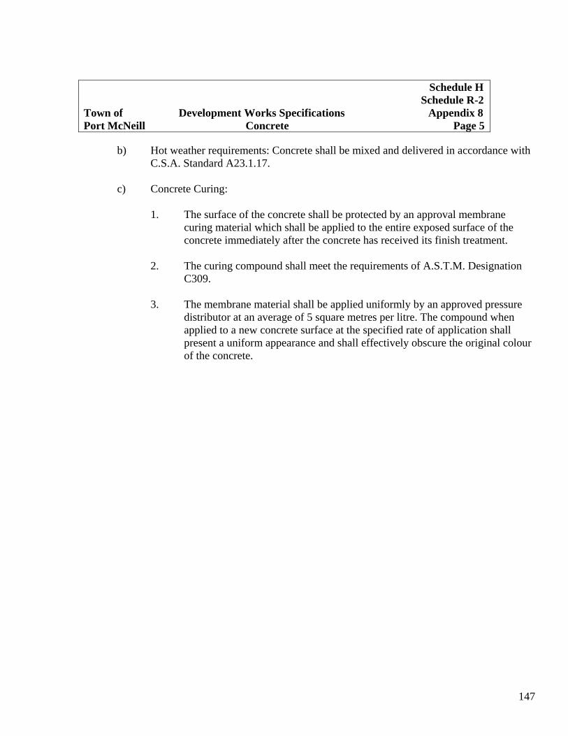
147
b) Hot weather requirements: Concrete shall be mixed and delivered in accordance with C.S.A. Standard A23.1.17.
c) Concrete Curing:
1. The surface of the concrete shall be protected by an approval membrane curing material which shall be applied to the entire exposed surface of the concrete immediately after the concrete has received its finish treatment.
2. The curing compound shall meet the requirements of A.S.T.M. Designation
C309. 3. The membrane material shall be applied uniformly by an approved pressure
distributor at an average of 5 square metres per litre. The compound when applied to a new concrete surface at the specified rate of application shall present a uniform appearance and shall effectively obscure the original colour of the concrete.
Schedule H Schedule R-2 Town of Development Works Specifications Appendix 8 Port McNeill Concrete Page 5
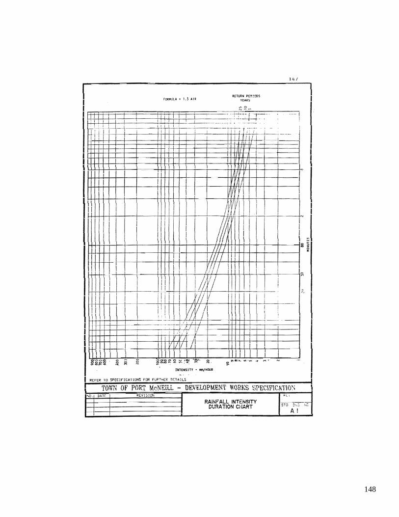
148

149

150
aoocru """ ,_ -.., ~\(l ..., CI)tjf/rCf TO ,~~ ,,_ """"0:-0 004lI¥
ECCENTRIC CONE / r _ '_. - ._IM_ -r
. \ UI. JOOoII'!. ""'" tnIf)(f _ ... ___ ~. • .... !10000 ,.~ _ ••
- ocn TO tlaIII ,~ f.»~;~;~e:!~;;~· ~~~·~-~~~~~,:~~r-i·;::;:~"!"~ Cl"IIOIl' >.O!lM a.o ~ '::;" 1
=1~~-::"7Y IF: :1-ll·;: .£ .. :-.. COO<JI[ft, ,~
.. ",OU"'"' ' I\.n~ , ... ".
~ =~D_C:'~::~::~' L~:::: :~~~~!:··;;~::l~ · 0tC';\._. ",- _ .-- --- AI l~~,=, ... ~.':~.:;:.:t;'~!:~::'_l *OIU .. 'IOU SECTION 8 - a ..
,",O' UVRtfO , ... . to ... 100 "'~T "",.nn,.,,,, --1 ..... .....: , ............ ",'M .. MU ..... , . r# ~(
.. K'I'D' ... ...:II.( Ttl n "l"I"''''''. 1 "(CIST moor CllLOD • "" IftTlOOlll fO C\IIfI'~T .u .... c ....
.. "'eo ' Ullt .o::NUMUI to u UlO .. ",0.0(.,
l ,~ "'''''o..( to"tR' . .. "" Otl. u III "0. ~a -- .~ .. .. " ... ' . ... . VH ""''''"I.UI .ce. 'bl.l-Ol . • • , .. ,coellO[)(! 10 II "UO . I'OS"K*t DI" ''''I. (I. VII"'CVI "".O · " ~ ,000/'! 1 '0 It SU ' , U \ 0:-0 ,_ . • , ' .... ~fLl •• < ... . ""c··· .. re'"·'~ .. .,.I ' .. ( .
,,~:< .. ... , (,t. "" ."., v!""" . " .c' '" <",C . , " "" .,,01 _'." .... " .. -..... , . ":1:'\"-'
. , ( ...... [LL~. UOOCMIIC 10" "W'IktO Ttln""", -,-.... • , t . " ""'"IfOT Ttltl LID 'MJ.N' 111.0 ... _
.... O<"'II(~ .
" ...
TOWN OF PORT McNEIU. - DEVF.J.OPMENT WORKS SPECIFICATION
" • STANDARD MANHOLE fOR UP TO a INCLUOING
37!) mm PIPE S1» IWG ><:
SO I

151
, .... ucuu ru \
" '" T' .. , ., ' ." " '=---11 .. ···\ : .... : .. :." .. : .. .;. ....
I I ,-- L \ ·:i
COl(.. (IC&SUOf 1.."-•• : . I, .. . . ... . . ." ..
f
f-
I J
. .-::.\,. :: . .-: . .
IrLHlt 10 ~tl"t""OJ<S r OIl! n.ltTMD III[UIU
n NX«$ 4 ="
TOWN or PORT McNEIll DEVELOPMENT WORKS SP~CIFICATION R [ Y] ," ,
DROP MANHOLE SO 2

152
"'~.'I'·""',c---,,1 ~.
a,,---,_~J _._._\ ......... 1_ .1!00_ IlOUC:U 101 U . ~C.O
...a._ .C_C~ " _""0,",, "PC ~ ~Alt" • ...... -.
' . -.;u: t;OO . .... 1IWIC III./U 1011'_ """ . ,.. •• 1O1.
Z. 'I:IP' tT ~ 10 • , __ OI:STIOIC "'_ 010 ~ e<II ~ ... 1111 __ I'UoC[D SUIrMl _~K_
:a. _ OJ( _ co.tII 10 I( PlU5lO """ IIC SI.Wf~ ~ t<JlAUG __ ~ !'OIflION Of TIC -.
.. IOCICTU. -.m4 CUM ~ _ a-ICT.
L C» 10 lit ~ IImtOIIf Cl5I<n.
r-"~ TOnU~"'"
TOWN or PORT McNEIl! DEVELOPMENT WORKS SPECIFICATION • ."
CLEAHwr
' . SID ) 101(; 0(1
SO 3
(

153
• J
SECTION Of ,,ulol( THiIt(lUC;H ... . A
~ __ 10, ....... " ~'" I, .. C"'"'O (It< •• _ .... . ;o~M_ ",n DOIIO. ,It.
TOWN or PORT McNF.ILL DEVELOPMENT WORKS SPECIFICATION •
200 mm MANHOLE COliER 8 fRAME
SO 4

154
," .l.UD STDII" OIl.l. IM t..IO ( 'O~ vS( • . ,",., '''''$1
I .... - I I~ZZZZ2Z~~ - -.,("'_'~ U""''''''''Tlln-nu • ....:t _ ....-J _ _
TOWN OF PORT McNEIll - DEVELOPMENT WORKS SPECIFICATION y I I D!<
I()() """ MANHOLE COVER 8 f RAME STU DVG. >CI
SO 5

155
TYPICAL HOUSE CONNECTION
._ CCOOotCToQIO) Of\oU . .... " 10CLI ...... , _l~n. " It OCCOOPlIe; TO .c...,.-.. <OOC
uu; ~ IIOCI$ __ OUT 011 '>01'CIU.T
AS M~ 10 Wlr1' ~ QI S!IWC:III' -- Ql_~
, , " .' . o • • 0 '. 0 , 0 , 0 0
• ' . 0.. 0 0
·O'::O ... .,~ :';' 0
0 " . ' '00 • •• ' .0 ..... ... ,0 : ... · ~ ·:O· ·O: O
Co'NNEcnON IN A DEEP TRENCH
10<05 ~ " U)CA~ ~ "0000 _ "~'$T
K .tOOU .. ,IIo'-'tl. mtl'DO .... 10 ~IO ~
__ SUIO'OI 10 """" W'f'DI
0<0 iii IlIOo(IO ' OU
....... t SI.OI"t: 01' ..,t'lS Iotn """,' _ . 101""'. :11[._ _1U$UI.....sT • IIotO<IUUI _ ""'-.0..
.... (· .. ·I$"""'t.""'"'" ~ 011 w.Ii..I. bI 1TIOOOI 1$ _ ~ 1M:
_ CTOIWfT" ~.~
TOWN OF PORT McNEIll. DEVELOPMENT WORKS SPECIFICATION n ,
GENERAL SERVICE CONNf.CTION OET ALS u • .,.... 1<1
ORAIN & SEWER SO 6
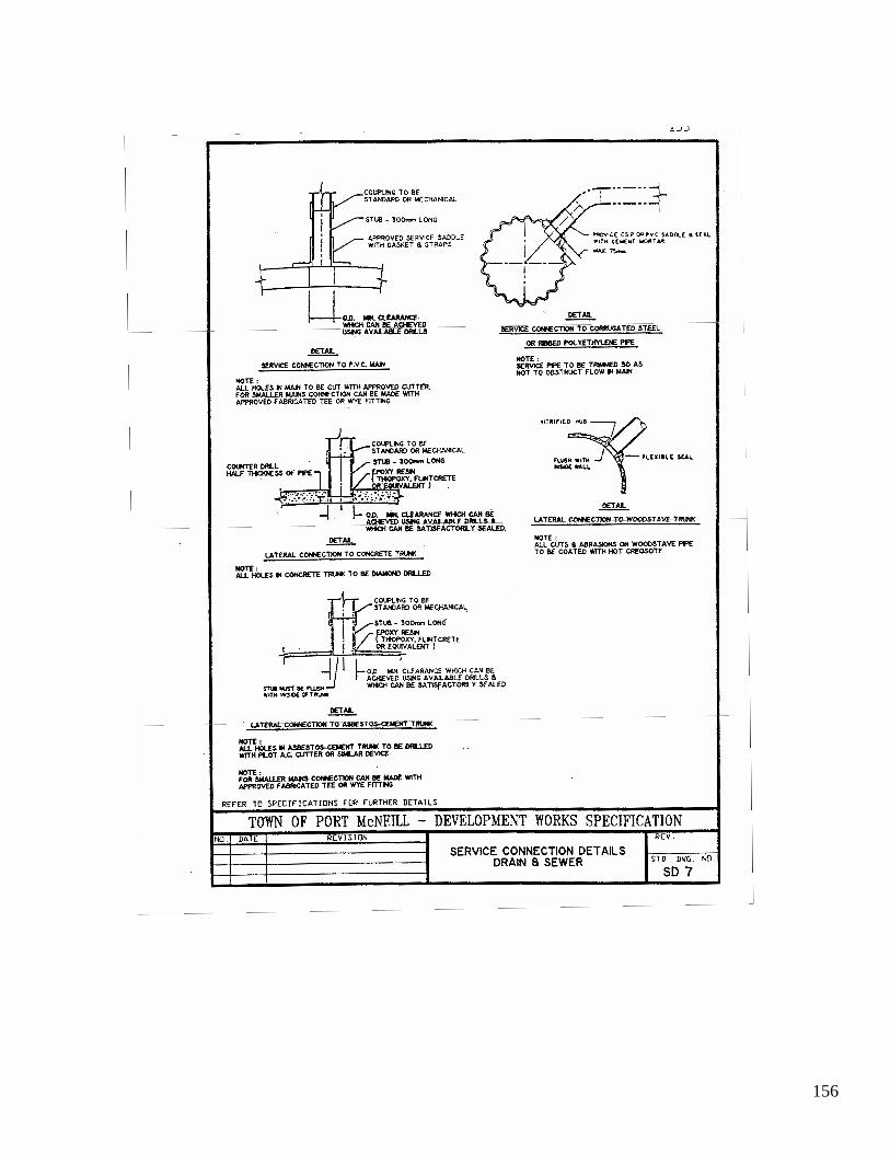
156

157
CLASS A
CONCRETE CRADLE LOAD FACTOR 208
c R1GI~ 'II'( OM~1 )
ClASS fI
fIRST CLASS BEDDING LOAD F"ACTOR ~9
1.0 . 11(11' " .) O.D •• W ' Slot 01 • • 1.0 • • InlOf 0 1. , 'OI-,n-
. DI~T"U ._ "'lUIO 10 101' 0' '11'1.
110 . .. ,
8 ~ t;:Fj
COM~" [;& 10 [ M~. ~ I M. ; 28 ~ .. ,.
II ~.IIU 1101 0Yl1 n _ """ (010''''''(0 II IR ICIK 11111 • SIIOYU 01 ' _ II ' W .
~IUO I IfUJ.ll. " ... n DIYIOU MUI IAI. ' "U ,_ ""II , II01if!i .. VJlI;( U~.
OIACWllf ' k'C'O •• a:'l ll ,." ,.too Drult. \ U Il( \ ....... , 01 1I000(l IM!I n o.... IIU .
I. ··"""u 1 ."' ... IU, "'( l U VUUD _110M 01 'lIE RW ' GfII V£ ...... , 01 ",n l l l 1' 100 Of Til[ Ell(;( or IIf. IUy\ I UD _. ,., I • • "". " lI l If ""( fillED wIll t(M'A' I(O '11 · _ O;U.VU 01 I_l , '0 ",no'" _ Of IoIIClMI U WI, I ~ U .. l . IIHl ~ ' O .E "CU IUID wnl I W IOI!AlI[ l,
l, " 01 I(Q 01 OIlIU '_.UIIIl f MIUI",,', Till! IHK. IIIO.UI '" (M1· nC,IVUIl> i " ' " . Of t~o.. n<;JI ' II( ClITliN Of OJ:iUI'1.IKS 01 ~ll' or TIlE '1pt'1 ~ .UIlIED WIU aAaII.U .. TUIll. . IIWI . i'CAr"" I IU • "'-I
) ." '01 ' •• • C. ""'1, ROOINC TO If CCII'AtTIl> TO . _1_1_ tJf 11'51 , n> , f'IIIKTOI t{nlll WI U '" I II: ' _1" MU'.
'." l lrs stCIiOM 1_ •• " I I . 11_ ~'AC_U'I l(co-oI:*>U R:DllIlHo .lJilll •• C.:I II II _C. S"" CI' l tAII OIII II l l l _ • • •
. Z ... /:t,UO." C" t OlUl :K..) UClfl lL M".UI I. '" K U$(O ..... COIfACl(D I. 1$" ~UU1.
J .",4"'[IOIUl " 10 It: $oW M .
RCr(R 10 SP(tlflt"'IIIN$ r OIl n,IRTK:R D(1~ILS
TOWN or PORT McNEIlL DEVELOPMENT WORKS SPECIFICATION
'" CLASSES OF PIPE eEOOING fOR SEWER 8 WATER
so 6

158

159
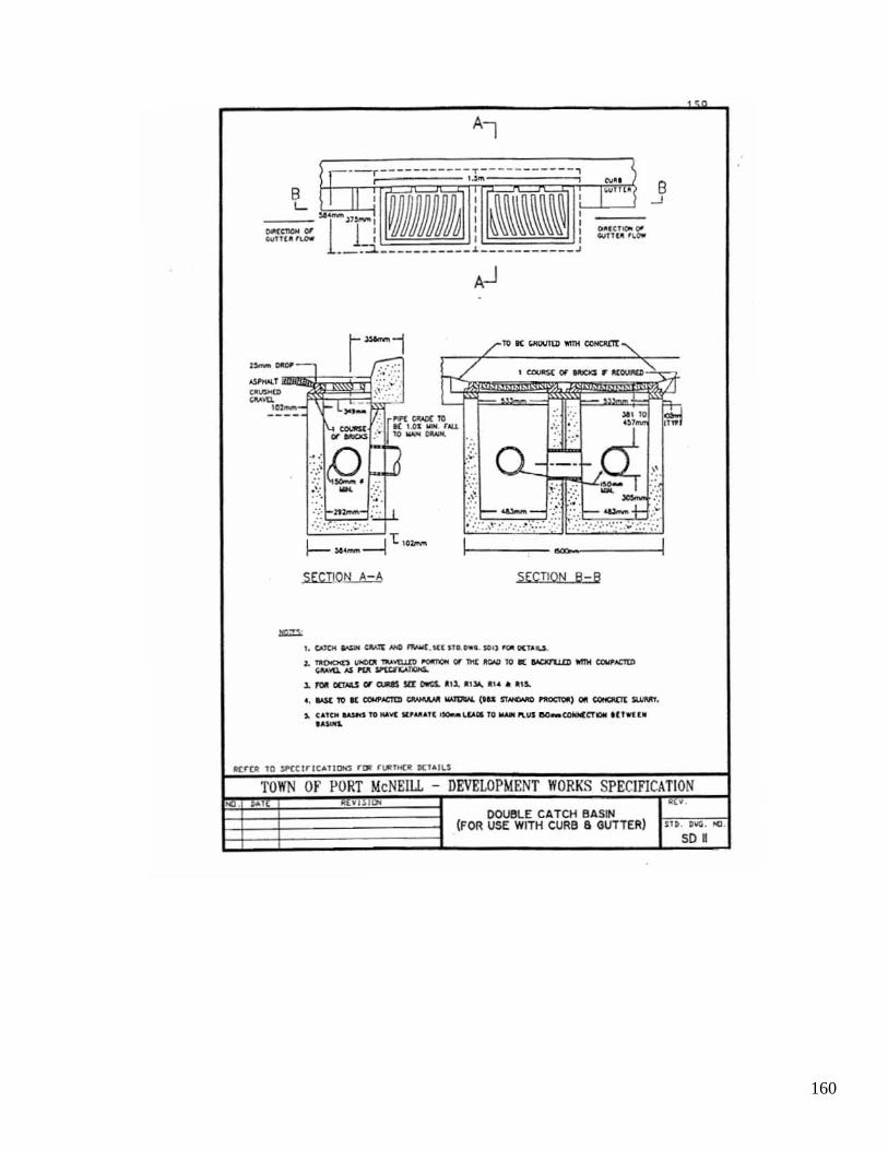
160
,---r------ -- -T-I 1 .).101
B II ' , L ,
~-Jl~ , __ M
lJ MJJJJJJ~ , ... nu',- ,
______ ___ _ J._
,..- . . r- """" CD\.OIU :.: II[ ' .n _ . • .ou tJI'_ :" 10 __
.... Q ":.\ :.:: _ . . ': --.-',
. ," n:z..-
.:.:: .. :.:.:.~ .. ,
.. . ~.
-- ---- , , ~ .. I'" •
~~~~~~~~ , , , , COOl"",", 0-, "'TI(!I . ~OW
-- _ ____ J
SECTION 8-8
•. c.uo\ ___ .:IW'E __ . Illl.LDooI. $'U, _OCT'U.
1. "'OOOCS __ 'o'IIJ.n I'O'ITO'I Of TIC IICWI IQ I( ~ _ CClWI£ltI)
~'oQ. ~ "'" ~ 1. ~ OOM.S 01' ClJIIIS sa DwCS.. . ,1. ~ I JoO., R'~ .. . ,S.
8 --'
" _ 111 I( elH'lCTtII ~ ~ ('U n_ ~, 011 ClQIQC!t $U.M'I.
i. CAl ... _I TO .... 'oC Il,. ,ult _WOl to ... P'lUIIIO_ CONICCTDI ' Uwt .. . -TOWN Of PORT McNEILL DEVELOPMENT WORKS SPECIfICATION
Yl lllJ'i .. OOtJeLE CATCH BASlfi
(FOR USE WITH CURB 6 GUTTER) SII . D .... . >fl .
so ,

161
: ~.,; -
~fl ,
f-! ,
1>--<£. . , . ,
It _____ :
/ n AN
to ...... Ir_ _ ..... ••• ,,0)
/;:~-"-0 ,_ ... ., -'''' ...... .., . ; " J.
_ .... T ....... . . .. , ....... '
... "". 100 .... ,
V~ , U,\
',-) ~' I .. J:- . \--7~' .
. 1' ~,
"i- t-.~p ster 'QN. .-.
""'-~ _ on ... , 01 GUTU '" 11D. 0 .... 10 ...
l. . C- I>£T£U 01 c,.,go USIN$ 10 o .... ~ c~ •• ''''TC~(O . c.o._n sa ITO. __ 100(1 • 'O ,~ --1 10CI<'1U. l'Oat C~UO'_(~ .
• OQ!O un '" MlAi .rr"OUT WU ' C",,,I\.
I!(f(R 10 If'(t !rlCAlIOm r~ fl.l{lH(JI on"'lLS
TOWN or PORT McNEIll. - DEVELOPMENT WORKS SPECIFICATION ~ . '" • I!~V.
SQUARE CATCH BASIN nD . DIIG . ~.
so 12

162

163
I /
A L
I • L
~
,, -·~' _IO .
1 11"-,I
1=, .. __ • 1:).- .... _
!
1 ! I [ ! A
! I [ ! Ii ---.J ! I, ! '! ! I I !
II ,~
! ) , ! II
,..."".. .. , ... ,
SECTION /l - A
IIIZ!D _ ."""', ... (,0.'''' .....s- . .... 110 -.to .. _ lOX .. . out _ ...... "'""" _ IIIU.
_tlb ..... .. " rJI _ .. --.. 'II . I'UoCU __ " __ (To. ... f1IOft'IC'...o-.
, ..
TOWN OF PORT McNEILL - DEVELOPMENT WORKS SPECIFICATION (VISl ..
SOUAR~ CATCH BASIN FRAM£ 8 GRATE
5014

164
rc @
r i=
S' ~,=-O
-, o 0 . 0 0 0
~- 0 , 0 0 0 0 0 L. _____ ____ J
r· - i' - i' - i" - · ~ I' • • • • I o • • • • • 0 : . • • • • 0 0 o· • • • • 0
" • • • .. :. . . . .: ~ "-"1-r: .. 1.-1."
,
~ 0
1 jl p-
! I
~ ! ,
H-
-
11 ,. a ('i ...... :.
. ~
h
i
I
,
" • . I I ! . ~
! I
1i7.'I-;r,.-.,..,.",,,J.,-,.,,-:J.'.:.,:' . ~':' I ::\.::? ::·; .:;:~:~~ .:.:.:.:,i· :;·;:.:::.::
!
h
TOWN or PORT McNEIll. - DEVELOPMENT WORKS SPECIFICATION ." COMBINATION
SL T TRAP a GREASE INTERCEPTORS SI. DW; O(l
FOR COMMERCIAl GARAGES SD I~
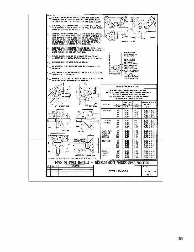
165

166
---
1110(1'("0/0'
u .,.,. ~. ,.,' UK . OW ' ~ 0,11 ·0.' VAl""
", ,. ~"" .~ l - n- CIUl l l1l I . e . !'Ill .... ,-... . < p I - , .~/8" .' ,., .•. ~I _, ®
rO.T . V~lYl 1<* =
/""LV! 11"_ / H' • • IU. 0;.\.1£ Y .... ¥(
i I !O M DUfl. U'U 1M !lILO
I "" , ', 1·_ ....... ,
r '· DU. 1I1 ,IItOI
:\?,": ) III . -, '. ' . f\.r/ ~5~/ "Ieul
(OJ'IUI 'UI '. ,....... . ....... JOO"' ... . . ,_
~ ~TI TOMIAI !!loti[ ' :" " : " '.~"""" U.;i?iifP/\\:: . " '1iI: uu • . .0... .• . . o 4t .... . O~ I . (;lAwn
..
6Il:r[R TU $>'£crnC tollDHS HW rI.I1 THCIt (l(TA'Ll
TOlIN OF PORT McNEIlL - DEVELOPMENT WORKS SPECIFIC TION ~, ~(v1S1 I !I~¥ .
FIRE HYDRANT ASSEMBLY '" ~ ~ -~ r ' W2
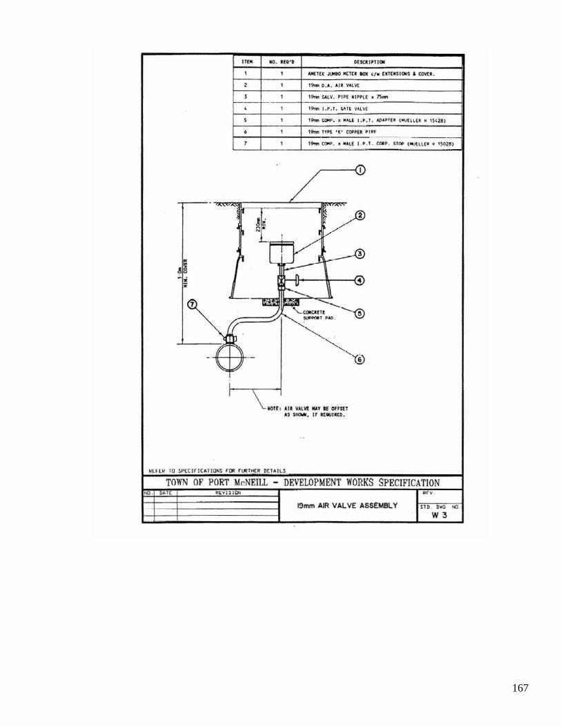
167
' U M 110. U t'D DlSClt"lI~ , , _If~ ___ OI(IU 1(11 <I_ UIUSTOtIS , aNti .
, , ,_ O.A. Arl VAl\'(
, , , ...... CAlV. ~rPt: .' I" H • /'S_
, , '\>on 1,1'. 1. CAll VALVE
, , ,_ ","p . ....... " .... 1. AD' .'E. ("'JH". " '~\nl
• , ,_ ""I '(' ~Pt:1 .,N
, , '_«oW. ' "" Lf I 0 . 1. emo. Un. ( "~IU • • 'S02~1
.~ / ~
I
~ ; ..ftJ .//
-~ -0
!i n '" ~ ~
.. -------'-~~Ilf ~
""' ... , 'AD.
""" .- '® '-.)'
i I
\ IiOU, I II YAl'o'l Ml.l I{ GlfsU A' '.eM, II I f "'II(O.
'(U UI 10 ~CC lftCAliONS rOIl nfUMC~ D[1All$
TOWN OF PORT McNEIll - DEVELOPMENT WORKS SPECIFICATION 00 . • RtvJSl ., .
t9mm AIR VALVE ASSEMBLY S1II . D'o(; ~ .
W3

168

169
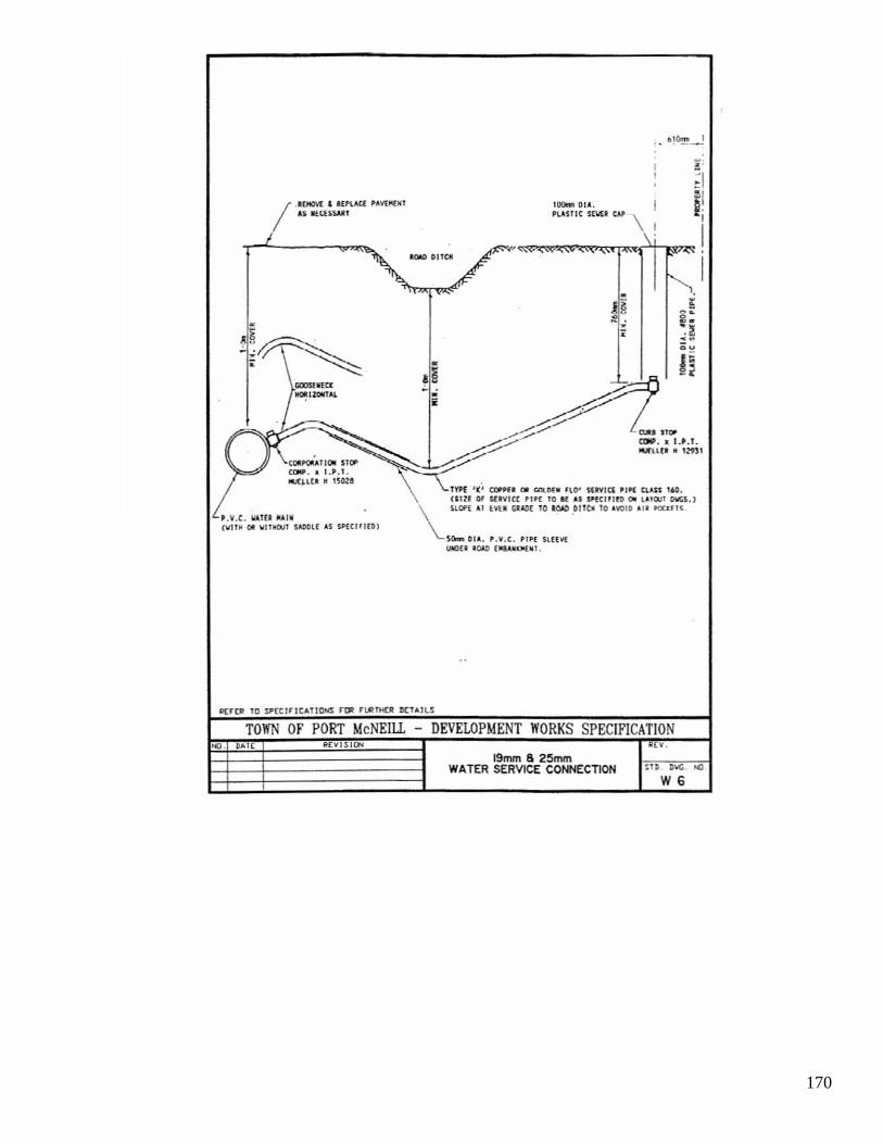
170
_/ IV4O'i'£ • 1(~lACI 'Avt"f.WI Ai IIn UU,1I
100... DU. Pl..AU1C n'-"I CIoI'
. ~
I
\1
TOWN OF PORT McNEIlL -- DEVELOPMENT WORKS SPECIFICATION II(VISIOH ..
19mm82~ WATER SERVICE CONNECTION StD . D ..... tel
W6
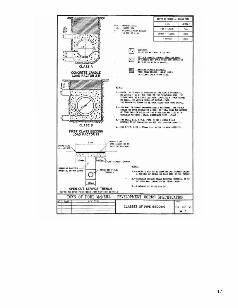
171
CLASS A
CONCRETE CRADlE LOAD FACTOR 2·8
CLASS 8
F~ST CLASS BEDDING LOAD FACTOR ~9
UIoMA'" -..n:IIU ou.TlI' "l (. ,." t5000l
I-I OPEN CUT SERVICE TRENCH
0.0 . Mil Dl OU , I . ' . . ' ~"Of 0' ".
Of'TI Of "'IU 1 1~ "U:O' PlIf
' .0.
<(1/1' .~ • oru llfC[ I.~ folOJIl)
10 ,~ 01 'TO(,
• ,_ 101m>
""""-TO" l1) .. ~ _ ' " . a u QU S.
, [Mis ..:o _ I """ «oIOOCIB n ""rei", VI I_ • ,.,.u .
~.!r( ,ugo '9'Ul ' In ,_ OUIII, I,M(,( UI IM 011 1I000U OYU ISO- IIU .
1,··\00( _ 1111 l U O'[lHO _1I0il Of lill _, olin"",,,. 011 W II~' " \ · 001 Of Til ( alOE OJ llIE I " \'lUIO .""' . t o!( lUlleM IIHl II .... eKli l l u IIIIM CClPIoC I(O ' 11·1", ('un, 011 ( ...... TO WI'''. _ 01 ",cue IMI. ,. _ , " ,''' _ TO R ~'HIO IIITI _ GOn!.
2,·· '0. ItOa: 011 0101'" UCOW'IIusr.u ... IUIII.I, ,. UUCI lIO.UI N oWU ' UtolVIUD • '''I . Of I~ Utili Till IIJI I'DI Of ~IIIC;S 0. nUl Of ' Ill 'I'IS .. IIUIUR IIUI _Itt ou.1U ' ",. ( OW; , .""fGAII Illl • lloo.l
] . " 10. ",", I 01' . '.V.C. ' IP( ,< 0.. ~o, •. ) 100'111; TO I( ~OC1(O TO _ $10. HOCTOI. 11("'111 .
' ,·· 1011 ' ••• c. 1'1" • _ 01". un. 10 lUll m" ·1'.
I. ' · toIIe_Clt CAl' II 10 1~1tt 011 lKIlI'UUfO ~ I M'M' _ or _ 011 U t. ,,01: III 'Ill "'01;0.
2. · ·~ (IIrlalS H-l -.wzfl ll ... IUIII. " 10 I( IlUD __ IoCIU ' I ISo. ,UO,.
1 .·· .. '<'("'., 11 10 ..: Sill .M.
~rCR l Q lP~t l "IC"T1QNS 'DR ''''I It[R IItl.ll~
TOWN or PORT McNEIll DEVELOPMENT WORKS SPECIFICATION "
CLASSES OF PIPE BEDDING
W7

172

173

174

175
I ".~
I I:0IIoI) AHCI.II.HC(
~ I 10.a.
.. '" I
o.
[~"~ I • t _
. .
I/- .~~ . .. , I ~ i •
2.00x 'All
~~ 111 111 .. 10M " 10.)$ c;It~l/Il . ~
Yj ... I • 46ORo . no. 111_ ~1f '~1,111 Q,\,I/I l
,.""
Id.'LK IU S/'lI:H ICAliutIS r[R n'UKl! DeTAILS
TOWN OF PORT McNEILL - DEVELOPMENT WORKS SPECIFlCATI ON ~ nATf " ~E ¥.
- TYPICAL ROAD CROSS SECTlON HD . D\IG 10.
R2

176
. "-
I - I _ .. tt, .... «
.. ~ f r ' , • • ,. toNI u ua
I
J ; , i r E .
• j I , ~I
w.~ I i~ ~ ',.-~ i •
• •
..
I!£J"CII TO SI"[C"IC~lIONS Hili 't.O'tHf(II «TAILS
TOWN Of PORT McNEIlL - DEVEWPMENT WORKS SPECIFICATION • . ,~ R(V •
TYPICAL LOCATION OF WORKS til . DIIIi . ~
20m OIW R 3

177
1'\ "i '" __ , I ~I '-:x~ " t""""" ... no <.MIU
c ",,, . - -..... \ 1\.,. II ; . t /~-., ~ - ,
t ' ,' / '\. t T"---J..--: ~-. -~/ / ---/ .;"\ / ' ',' \ e I - 114_ ' 2 t t
:;! 4.--. .--- ~ 'lI ---r- - -I II _ ....... _ ___ - J '" '~
t " / t. -'-- -+----.; ..... :::,... )/ / --
• •
• •
• • · .- , • • -'---I----.::,~.
---TYPE I
'- / ---T'fPE Z
.'
~ .
• • TYPE 4
~",_"""-.TO ..... · _'"' ~ __ -...:, ..... CM'l\.UIU.
~ __ IU TO.""""'_.lH. __ '"" ar.T»Q,OM _ CP C\M
"'* WI!IJ. U CUf1"K.UIlI'llOO"u.
T------·-'-- / - - - - - -t - /' ~ ~ , __ _ ;-__ of;
• " --- -1 · ,-- -:;:--- . · ---' ,-'----+---: , •
TYPE :3
TOWN OF PORT McNEILL DEVELOPMENT WORKS SPECIFICATION
TYPICAL CUL- o£-SACS

178
, ..------ - --- ----
, 7' / I '
-'-~ Ii I ~ I -------------, ~ I "I , ' _ L...l
HAI.4M(RHEAO n"PE
1 ,
R I I / ~
11 <-
'\ I
.,.
I , ..----------~
~ ,. ' '''; I ,.
I J I !-oj
-----~-------~---~ ~,.
,..... iU TUIJ'.~ TO I[ A-.L' ..... TU c.CfIT"""-UA
'(II:~~M.1lUU10"11I.C>W_. fOO.~ ..
TEMPORARY TURN-AROUND DETALS

179
, 1-"'" ~"~-----r-I lO!J,ll "lUll.'''''' ! _ fl_ UoI'. ~C'I'U "" " ... ~ : _ _ I
.-=--~:~~:J:'---
""" "\ _ 19 IIU.OW _ I'\INI( ....... ___ _ -.u< coct'Iou;n;ro. __ • _ fNSIC .....-__ •• • , _ ... n£4llTOI ...... _" _ o.TM ___ . , __ ~IIIS'"""I:~"" _ ___
1. ____ _ <Jf_'."" l lll!oo IlKOIIt'IoU. " '_1
l. __ no[ COIfN: ... ItIE DInM ....... _ oar " -.. nw. ..... Off ,+I{ tutr .. ... "'" ~ ou.-.r. _ TIC U\o'I!I.Clln.uoa£._ , .. COITlII Of _-"'1UIIWoIoICC.
II(H~ TO oSI'CClrlClltlDHS r!JII n.RTHtJI DCT~lL~
TOWN OF PORT McNEIll - DEVELOPMENT WORKS SPECIFICATION
" ., , ..
DRIVEWAY GRADES lTD e-..:; O<J
R G

180
CREST CURVES
--, .. -- --- ~-! -
--..:.---- . "'-------,
IIQ'·' o.o .>C.' I,,, .. et ,., "u', • ,. , nl'" ,., '" ~ .. '" ..' ,_., "- x."' ..... ::,,1=" _ .noo(lolU.,
~ • .c • ~. ... .. .. .. , • .. .. • ., .. " .. , ," .. ..
• , ,. ~"'u ''''''IUI I( _ .u, ...... .., ..... "'-1& , • ......o~(',.u '11 _ .
'" "".OOO'''''O~'''~ .. _ "~I '" LI. '" tun", ""'IU .,Itl .. "", ooC':'OO .... ~ ..... Of ' .'.1. TO ... . .. , .... ,.
'" IUID 000 . ",0 ~I""- """"_ " " .... ~ . ... "~,,, _"0.'" $Og ••
'" ....... _ .. , ,, 'U<'p_ ' .. CT 'D_ " ". " 0 ~'.'CT _ , ,,,, .~, ,10 ••
.!,h • , • • 1.' ..... . ,. ' ''''.0 .. ('~ OVI '" .""'[1 •• ,,;c,.,'. : .... ".."'1 • ~ •••• " .'Cl ... 1 _ . "' ''u. no ... ~ tic •• " , . ... « .. "U"U .... (Oc ... " " "'HI . ' . ' ..... ~' .. . " ....... .... 0 ..... '" 0.1" , - .. r. ....... C,.It'l' , ' ..... Ill ,.- ~, .... n." ........ 0 ' '1<1'' - ... "" ,. '1_"'.'
lL ' 1(6,(
" SAG CURVES
~-~ --, --=-- -;::---- i , --- , -- , , , , · . :u,'" I "'0"'0.0 .. ~ .. : .. , ., .... u .. .. no ,,6.' """'.' 'O".",., I " ,', I ...... ' '., " ' l rT ,.(;0<"' • .~u- " c. """ .. , .. " , • .. , .. , .. ' . " " . " " . .. " ""'U ' ''"'''"'' 11 ._ , III ..... oem ... u~ " .. I,O.('I·U -'" -... ct'''''{To .. .. (1" '''1<)00 ,-, .,.'
litre!! TO Sl'CtlrlCAHOHS rCR ft.«TH(~ OClalLl
TOWN OF PORT McNEILL - DEVELOPMENT WORKS SPECIFICATION 00 , • WHI Rev ,
VERTICAL CURVES FOR MINIMUM STOPPING no '" ~
SIGHT DISTANCE R 7

181
SUPEilEL~VATION AND MINIMUM SPIRAL PAR,.J,METER. e MAX . -0 06
I ...... . "t~ .. ,GoI • - ".. • • ~ ... . .. U(~ •• "'I"" OOC - _ ..... , .. ,n .t~Tl""
o~ o~ .. , .. ,
oc_ ' t_ .e.t ·"~~ _-0 Wlt.1U~ .. t or _u~ .. ,.., II· .... ,p,c:no , , . ' . " e<'" SJ" . . ..... 00( ', •• '" .,.,"". " 0 ~,'''U "~.jU 1I'0Il\..) 0(
vln . .. t". ocn, ... , ..... .., ' '''11: . " .... 1.1 ..". .... Ino'" . . ..... , "'( "r ' " .,.e ' 00 .·,",~I " ' he ... ' . .. e. ( '" oos_r , ... , . u ' ·"~I .... cu.
n .c .. h ( =0 . " ...... r ~u . ..... '" ·,..."n , '." 1_." .... 0.0 .. "". "' .... UII "" , ~ ..... " " "'(~ os I " ....... " v( . '~'
0
0 0 . 0
". ". oN .. ,
TOWN or POR'! McNEILL DEVELOPMENT WORKS SPECIFICATION Due (VISl R(V .
SUPERELEVA TION ~U . DIIG . tel .
R8

182
~ .
.: ... . . . ..: ..... _-.l 1 .... ---..... --_--',
toOUIHAIU CW:. 1&'10( stCTIQIIt)
IU"UllO.1D.1I'MI._1"'0II __ .'U10l_
r-I --~----II
~I --------________ ~I
TOWN 01' PORT McNEIU. - DEVELOPMENT WORKS SPECIFICATION , VIS! ltl MOUNT ABLE CUR~ ( WI>E SECTION)
AND INVERT GUTTER
" . no DIIG . Nl .
R.

183
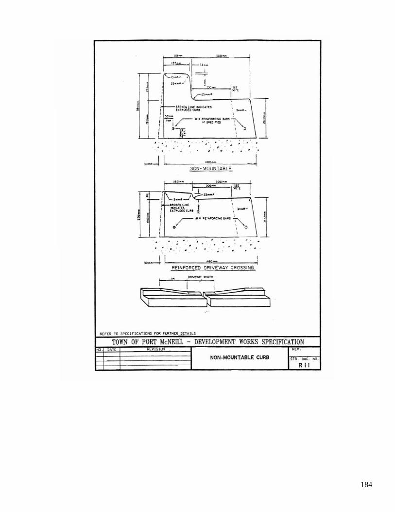
184
•
---1 <--I ~~ .. '~-~--!I .'tGN -\tOUNT AHL ::
: !
l.lf~ I , i -
. . . . . . . • . . • . . . . .
-
, , -,
. . . . .
. . -__ -1 1 ~ ~~ ... -~-~~!
jlE!NF"CRCED ORIVE'N:'Y ::<ICSS ING
,.
1
TOWN OF PORT McNEILL DEVELOPMENT WORKS SPECIFICATION .. , . ,~ NON-MOUNT;ABI.E CURS UD. D\I!i . ~
RII

185
,, -
C ,;.:#::',"'t::~:~t~n ''W~'<>r _-_,~.~ 7/ jl i
Q.OII :c:::_ .. ..,_ """' ........... _ ... _,,~ 100 _ U ~_" __ ~ "'_~
r I
.. , .. ,
, , , , ,", i ,
-'-
, r
... ' ..
SE?4RATE!) SIDEWALK ... - :
...
r , , • • . ... 1. .. , .. .... ·1 ......... : I·, .. • ........... , ............ ' •
REINF"CRC ED OAIV(WAY CROSSI NG
=-
I ,
......... '
..,..".. ..... ..,., • _"'0: ... 000 .... ,..,.. _ . ............ ~f'OO
...... '_ .. cD ......... .................. ~"'., ..... "O .. _ , . pu"f>ooo. , .... nu.. ••• ..". ........... "' ...... _ 00 ..... . CI...
I . ___ .. ocnc.w.. OlD ""' ........ _ ... . nLy >0_ .. 0.1 .... ",...,~--~ _. _ ... tour. (O ,00· ........ , .. uoc .......
IlE r (R l O $P(ClrJCA110NS r(J! r l.ft rH(R OCU 1LS
TOWN OF PORT McNEILL .. DEVELOPMENT WORKS SPECIFICATION ~ . . • ~ ..
CONCRETE SIDEWALK $l D. U .... . N) .
R 12

186
"! e
CROSS SECTlON CET.l IL
.-..ur. ......... lOIftoun 1I) ......w. LOoO ................. ...... 0_ .. us ... __ . .. ,,,, ___ "'IO~ •. • oou~ ~-.u.a __ :IO'ta''''''
L ~ ~ _"'0 _ ... 1"VII .... __ ~ __ ...... <DC.IoT"OO. --.. ___ ..... _ , ...... ... ~ ....... J"""'",.. ..... .. ou.v' noo . ..unu...,. l.QW uua ..,no "IOU" ~ loll ... .a_
. . ... T . .... ...... , •• _. ".('0 .... '" _ _ ••• "' ... ~."'" _" ~~
._~ ._._ ........,.._~ ... · ... _.o I. "'" ~ K • " , .. , ..... t:1I <0_ =uno ~ " ., _ ~' .... , "", .. m ~
.......... _ KGI ... ' . 0lOO.,, 'C ";0 ....... , ... ......c w>Of'IO
ASPHALT SI)EWALK
."

187

188
PLAN
~ ". ......... ~
'" , ,
ISOMEmIC VIEW
II(f(R 10 SPtClfTCAlION:i f Dlt ruulO OCUllS
TOWN OF PORT McNEIU. - DEVELOPMENT WORKS SPECIFICATION I1fV111(»1 .".
SIDEWALK CORNER RAMP SU . DIIG . Nl
.'5

189

190
"--'~ IInk,.I __ crul .. ncoc IT_'''': TO K" ~ """ _ f't>o<OOi OONUI'ot;T\OICIr , III: _ _ root
......... .... -.. -. ......... ~ ... ,". ru
'--,
' ...... 0.-...,...- • .,..; 'O K · '~UlC( _ 'O K
" TO ..,... ..-. ' '''' . ....
.0""'" _ ." ... """"" G"'_'~ _ .. _--.,..
.., ...... .,~ ' _ ...... O ... _ II ...., . .. K .., .. _.....-.;--!1 _ _ I..OotrosTt TOK KT "" ;r.-OU' ..... C.,....L ~f'I)O' .. ClTOK~'_ • ..-.. ", • -... "'_ 1CO'OOL CO\IO\ ..... ,.,....TO Kon_"""-=wn_ .... .. "' . ... _ __ -=OU . ...... ~ 10 ... , .. , ftcrc.troo. 00 ...... ~oo.u _ . ... ~ --. ... ... , ...... u __ .o ... .... u .. a...uo •
• J1 ..... .-
nn.co , OOOC .~ {If TCrI, ov.a. ue.o.. !tAL. .. INri ...., _."_ 1C .. t.oI.~ __ " ........ '"cn " IU'I'I.1D .. TIC fDUOI ...... ~
__ • ....: ,. ... -.u.m "" ""'"" _ "" T"DICL
........ _ .. I~"~-.L."O"U,.....,.--. __ Ill
'"" .... _ ........... . itU __ _
TOWN OF PORT McNEILL DEVELOPMENT WORKS SPECIFICATION .. CHAIN LINK FENCE IOU. DIICi ..:J
R 17

191
~ . .
KC _
... ! ._ . • C ~~ , ." , ."
"Of 111(1 _ ..G"'_ • "'uu.o., ..... '._ ~ Of .. oro ......... e. Of on_,.& -.J. "-C_' 00 "OC'O'" " ,,,.,
.... OO(\.ZIC ,ICIO U "I . ~nD .. ,." ....... COOO 00 (oo.o~6I.DOT •
.. _. flO ' "
: . c. "C~., . q ... .
~"iYi=:J ~. o. J!Of"' \O a*-~~~--------, p -, .. , '"
1--. I !i --.J~l-,-..1. __ l "clloI , :: ,
TOWN OF PORT McNEILL - DEVELOPMENT WORKS SPECIFICATION Rtvl51 Rt V .
SIDEWALK HANDRAILS SU. DIIG . ~.
RI8
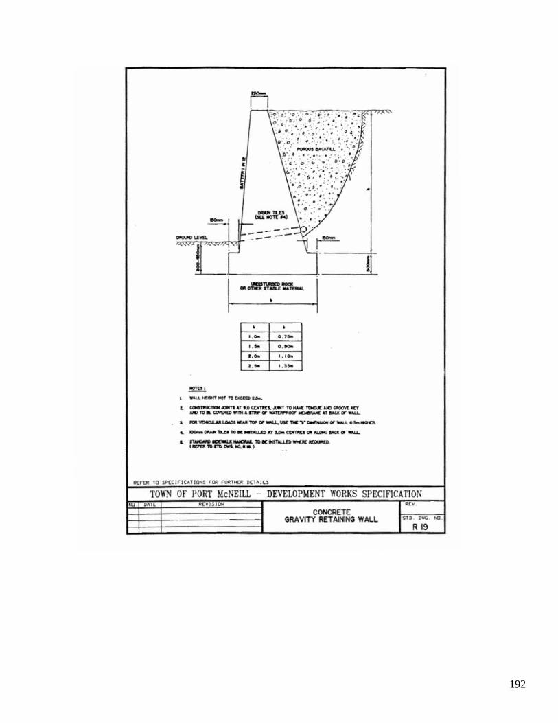
192
• •
-n
~w:.) - ---- - --
•
. . .... 0 . 1 '"
",. 0._ I..... 1.'0-
r." I,''''
..
.. COOOO1aI::",", --.- ~, .. 0 UJII1II(L ..... ' ", ... vr ____ I(['f _ '" II: W<'DIm _. nIIP 1It' ... ~ ~.T uu. fIT-.....
I
.. _-....UIoCIt __ ... -....UM:_,·_.,~O>o_
... __ TLu "'_...........n.r "'"' ~ 011-'" IloO< 00' ......
.. 1~-.._"'.1Ott0UD-.:~ ' IVDI '" mI.-' ...... )
'fOWN OF PORT McNEIll. DEVELOPMENT WORKS SPECIFICATION H VI 0'1 I/n .
CONCRETE GRA vtTY RET AJNING WALL
R 19

193
~
-
~h·. · . / · . '. ., . . ./ · , · • 1'0
. - · il ; .
\~ . · , • :/ IT.....: .... TtJII,I.l.
Il \ ; . ~lTnIf_a.. .. --~ -;; 11\ ·;/ -U 1000 t;O'T1I:[t.
~::lI1 '· i ~ I II \I \!) 1_ -
r .u.1'OINATt I __ ru:COII"C_TtZI_
--~ ~ ~ fa AI'.o.c.arr-..: ~_ OUT\£T, <:m<1I IT-c .... ~
""" • -....~ Ilo'UIUoo fa. DC_ I T A ~ __
, -" .... fa . _ OF OOC , .... , ~COOOO'f _ """',_-.
• _noc. fa _A~"'_u.uTlWl_ _ A ftI'rII fIT ." \.t.W "..,.\.a T-.. 1M: ~ .. r.t:oO 11) -.uc .. ~U '- not _ TO TIC ICI'I1tIII '" nIf .u..
' . &oCJOn.1. TOM tuNo, P'MI: _ , -.-..... ... _ .. _ .. 1IC ~
~rtll TO !.f'CClrll;"'T1[)H:5 f IJI nJIITHCR DetA ILS
TOWN OF PORT McNEIll. - DEVELOPMENT WORKS SPECIFICATION ~. " REY UlllO ~ ..
ROCK MASONRY - RETAINING WALL no .~ ~ .
R 20

194
n -,-.. ",::::: , ~~
~.- I, : ,~~"';. ..... ':".:~-. • ,
. """::"'''' 1'"_ , ;;:
.............. "!. '" " ,I AT ...... comoc .. " I .,
. ' I --"1.L , . ~. • -L
I. , 1.1 .-...om :00 C"WOOCTa> ~ ¥,; .... o6;.~ .O(! • .. M( """".~
~ , -...o<*<f ........ (_<'O IOCPI[OMCI.y .. ~_
• &l..1tJINATr YDmC.AL _ .... II: CIIT Of ....., *U. ......
• ~-.nATI.o..-"'-OII'_..-n"r, .. Q.Jf~
• _~,""," __ fT-u.. __ I'OIl""""'II.n..~ , PClD"f 1M; ... ...-r ,
• I TLCI&NI--" _ .... 1'0 K ""iO,UlI ~..".." -... _ JI(~
l ocrut 1'O.no. __ .... ~ ...
0 ~_ GOOO _~ .... .-~ CCOCIrT'IOMI_ ..... Df __ ........-.
0,"'11:" """ _I ' ~TOft«OOI;N'
"(Ie ... • • , YUI . I~[l _.Ultl
,.- ,,- 0.'_ ,,- " , ,,- , .. • ••• ,,- 0 . 1 _ ,,- "
, ,,- , · .. , ,~ .- 0. ' ..... .- " , ,,- , · ..
I. ,"" .- 0 . . ..... . - .. • .- " · ., N • • • •
..
R(r[1! 10 $p(C l rrCAtlONS r~ rl.llTt<R ~(to.ILS
TOWN or PORT McNEILL - DEVELOPMENT WORKS SPECIFICATION U"'[ • Vlll lJ'< Rev •
CONCRETE CATM..EVER RETAIN!NG WALL $U . ."' . ... TYPE A R 21

195
'<II ' U'TII ' I"' '' ~ ..... * "'-1.1 ~ • ,~ . ,
r- .. ·
· / · ..,..".s
__ " c .. ~jl ..........
· · I .. ·S .. ,
__ TU
i " AT ;t.OOOCl[>fTflU . ~ •
=·'I!Z.:I'·~"1 ·:Cl ·' · , -- .. :I • ~ I
W -,
• -....~oYDI. .'~ l'O.:CII:_".A~_ , M.J'OtO.A11:""""",,,- ___ .: CIII" AI -.. -.. oc-T.
• ..........cruo.own AI " __ <O'\"IIU,~~_.-rs.r_U)I'l'IIIU.
, _-..........-__ or-u. .. __ A-.... ... ,~1GCJI ! IDIUP'f _ IC»<T I
, I ' ......... -........ -..... TO II: ... TiW.n> ... _ or -... _"'oo.ocD. ' ~l'OITO._ooo. ~ ...
, """""'- ..... COCO __ ~.""''''''' ''''' ""'""'""""""" 0. ...... _ O(~D.
O".t NS,OfU OltNrOfl ~l>O[fIT
"'10'" • • , l ,&10 1 • .~ . _.nu~ ,- ,,- ,- ,,- • " r--;-:-z-"" 00_ 0. 30." ,,- • " , - .- o .U ... . - .. • . - .. • .'C_ • ..
, ,~ ,- 0.1_ ,- .. • . - .. • .- " .. . O'l'VoCl l .... 0 r UJlI w,,.,. . ..... l l . , I .. US'H • &I .. L, ."III ...... . ceo- CVlll'U .
fl(HR 1D SPttlrlt"!DNS rD'! rt.IIT>«R D(TOIL~
TOWN OF PORT McNEILL - DEVELOPMENT WORKS SPECIFICATION D.IE '" ,~ I ... .
CONCRETE CAT1l.EVER RETAINING WAll m "'. ~ TYPE B R 22

196
LJ."'''''RE '
'~(III .. 'w PIICS~ $OD IUOI uo .... ~IS( 2'-
~/ _ Til' .O' ... H(O PHOTD CEll ... 11 I'OlVC"U()<.1C II(TUCTDIt
1-I I I I
R-,?.Jr> I
- --- -~ I
, I" ~
I t<l IC S·
l. 10 I[ tL'1'l1rl tIN'tCT( IIU" · - IWIMU coYCt NlD ItI. , - IIJT cu<U5 , SHIII5. GiI09II:U _ IIoUM(8S .
,. 11\ ""' . OC:I/IIGIItOIL fTC(\, Sl¥lrT. I - 20) . _ wr .1 IOTT(JoI
- ~9 ._ loA ,,' ToP
l • • t'o'K.[lIIIP MT K SUJS'''IUTIO
I rOIl IIII' '(P( ,wtttT . il'MJ\llIl(D (II: DU0l111:M ""'" .... 'foNO( .. T ",q _U"ltc:O
1~~_tMJ.E • TOIl .... sr: UhlL5 $([ HD. M . ... I Umr~R loll( ( I IIZ,..."11"") <IIKN ~CU1"U) , r 305ft"
) . rJNl'I" 10 I( GA!.YOIjISU
6 ... ~ DUCJtt)tJ<1 OI!( """,-.
"'" I
"- -l. ~ .-NlLES ll . _ ~I • . [o.JI-SI'IIICCO CJt i!'9_
? I ."< I!I.T CTI!Cl.[ itT • •
1--"" - -+-X-t-f---- M)8"-
>"f -" "-..
I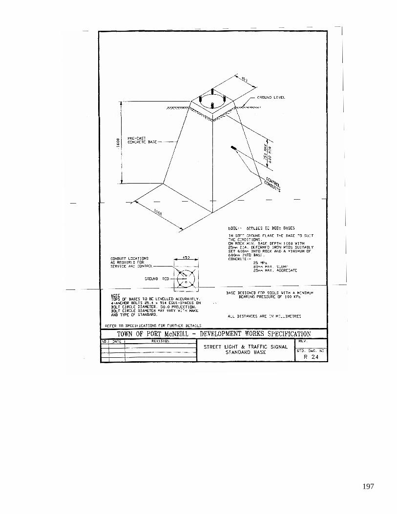
197

198
... _ .....ec 'C~ " "" ' " . _ .to _ _ .... .. ~_ .. '"""\
MAIN ~~
: .. " ,,( • .. 0< •• "_" ~_1 ......... u _t_ n- . ... _, .-. _ . , ... .... ~ ._ :i • • <.Ou.
CONC"ETt ap SE
1 1
SIGN pEH ll
LOCH ION QEJ.l tL
i I
' I '1
TOWN OF PORT McNEIU, DEVELOPMENT WORKS SPECIPICATION ... STREET NAME STANDARD

199
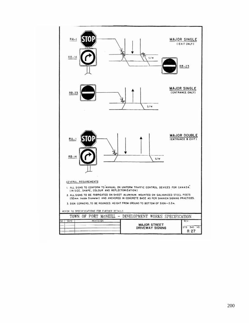
200
MA JOR SI NGLE I EXIT ONLl l
~ = 11----1 \1 i 1 ! \ ".
MA JOR SINGLE I EN TR ... NCE ONLY!
e MAJOR DOUBLE ~
1 i I ENfI'IlNC[ • UIT )
(0 RS·14 ,,.
GI " !U\, ~(OV'''['''E''TS
I. ~LL S I ~NS TO CONFOIIM TO-..... MV ... L ON VNlro" .. HIUF" CONUOl OCYICn 'OM C ....... O ... ~ l iN ~IZ£ . SH APE. COLOUR AN D RU L£CTOII'tAnON'
2. "'LL SIGNS TO I[ ' Ae"IUl(O ON SHUT AW "" NUM. MOU NHO ON GALY"'N Il(O SHn PO\IS I SO", .. I~.I~ I 0 ;0 .... ' .. ' AND "'>1(110''1£0 IN CONellEr[ ''''SC'''S PER S ...... II IC" SIG NI~ pR"'CTIeu.
) . 'IG N CORNERS . TO BE ROU NDED. H(I GH1 '''0114 ' ''OOtiD TO e onOM OF $ICN - 2.2 ...
TOWN Of PORT McNEILL DEVELOPMENT WORKS SPECIfICATION '" I 1).&1
MAJOR STREET DRIVEWAY SIGNING III ,-.(; o(l
R 27
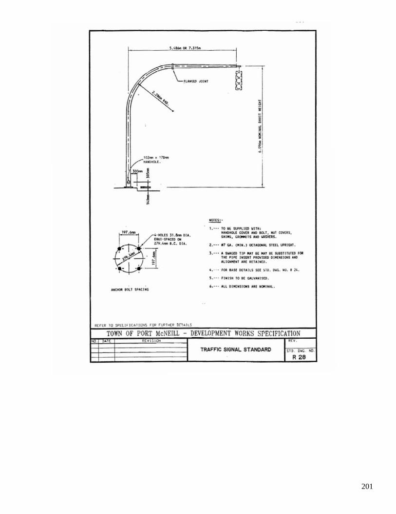
201
5.< .... a. l.llloo
I - ---K- \...~.lIOl .I ~l " .' <~
~ 10. ~ . • , i I •
01 ,
1/:0>_. ,_ i, - I
I oAIIOIIOI.L ,
t-! I :-•
.!!!!!!!.!. 1. ··· TO I( __ IlO IIITN, I,n'- I '· ... (111 . ... 01 • •
_"IIU t/M:. /dICI P.I . l1li1 awus. UlIII 'lI'l(:(O c. $1111$. ~1$ /dICI W/,l1l£U.
119.'- I .C. OIl . z.··· ~ "" . ,"".} a::UCOL\~ IIUL UPlilClT .
~] J .... A lI/oIo;tO 'I' I\A! IE !IA! R: MUITUI(D f IJI
~,.. ~- ..: 'II( _,'" ' oSlll ..-10(001.""0:.1 AlII)
'-'} '" . l ll'IiIIf..' AA( 1[1I ' IOtO.
< ••• • '011 ' AU D(IlIU $U .10. DIIe. NO . I l<. , ..,. ,
~ .'" n o lSI! 10 M '-'lVUIMO •
.... . all OIIll: . SllIIIl aU _ ,Oll . ~ lOll ",...cI O'
.'
II( ~LR IU 5Pl.Ul"Ical!Utl$ rlJ'/ r lF l'4[!> ~1AILS
TOWN or PORT McNEILL - DEVELOPMENT WORKS SPECIFICATION ~~ ( .. ,~ . ...
TRAFFIC SIGNAL ST ANDARO '" ,~ ~.
R 28

202
Schedule I Town of Port McNeill Bylaw No.414 Page 1 of 12
SECTION 991 DEVELOPMENT SERVICING AGREEMENT
(SUBDIVISION OR DEVELOPMENT) THIS AGREEMENT dated the ________ day of _________, 19__ BETWEEN:
TOWN OF PORT MCNEILL 1775 Grenville Place, Box 728 Port McNeill, British Columbia V0N 2R0
(hereinafter referred to as the “Town”)
OF THE FIRST PART AND: _________________________________
_________________________________ _________________________________
(hereinafter referred to as the “Developer”) OF THE SECOND PART
Whereas the Developer is the owner or has agreed to purchase and proposes to develop a
portion of the lands within the Town of Port McNeill in the Province of British Columbia, and more particularly known and described as:
____________________________________ ____________________________________ ____________________________________
(hereinafter referred to as the “Lands”); and
WHEREAS the Developer, by the “Town of Port McNeill Subdivision and Development Bylaw No. 414”, is required as a condition of ____________(Insert “approval of a subdivision” or “issuance of a Building Permit”) to construct and install a complete system of works and services required in connection with the said ____________(Insert “subdivision” or “Building Permit”) to the standards set forth in the Subdivision and Development Bylaw No. 414 to the Lands, on highways immediately adjacent to the Lands and on the Lands; and

203
Schedule I Town of Port McNeill Bylaw No.414 Page 2 of 12
WHEREAS the Developer desires __________________ (Insert “approval of a subdivision” or “issuance of a building permit”) in respect of the lands, before completing the construction and installation of all works and services required by the above bylaws; and WHEREAS the Developer has agreed to assign and transfer unto the Town all of its right, title, and interest in the works and services, as they are constructed, free and clear of any encumbrances for the Town’s own and unfettered use absolutely. NOW THEREFORE this agreement witnesses that in consideration of the premises, the sum of ONE DOLLAR ($1.00), the receipt and sufficiency of which the Developer hereby acknowledges, and of other good and valuable consideration, the Developer and the Town Covenant and Agree, each with the other, as follows: Definitions 1. In this Agreement:
“Approval” means, in the case of a subdivision, the Approving Officer affixing his signature to the subdivision plan pursuant to Section 88 of the Land Title Act or, in the case of a building permit, issuance of the building permit by the town. “Bond” means the security required to be deposited with the Town pursuant to Section 10; “Clerk” means the Clerk of the Town Of Port McNeill. “Completion” means the completion of the Works by the Developer to the satisfaction of the Municipal Engineering Advisor when so certified initially by him in writing in Schedule “C”. “Consulting Engineer” means a Professional Engineer, registered in the Province of British Columbia, who is retained by the Developer. “Municipal Engineering Advisory” means a Professional Engineer registered in the Province of British Columbia who is retained by the Town. “Warranty Period” means that period specified in Section 12; and

204
Schedule I Town of Port McNeill Bylaw No.414 Page 3 of 12
“Works” means the works and services required to be constructed and installed pursuant to Section 3 and includes all things required to be done under this Agreement or otherwise in relation to the construction and installation of these works and services.
Payments 2. The Developer shall, prior to the approval of the proposed development, pay the Town: (a) the security outlined pursuant to Section 10; and (b) all taxes outstanding against the Lands. Construction 3. (1) The Developer, at his own expense, shall:
(a) Retain a consulting engineer who will comply with Section 4 of Schedule “H” to the Town’s Subdivision and Development Bylaw.
(b) construct and install on the Lands all works and services as shown on the
drawing s marked as Schedule “A” of this Agreement, all of which are incorporated into and form a part of this Agreement, to compliance with the Town’s Subdivision and Development Bylaw No. 414, and to the satisfaction of the Consulting Engineer, to be proved only by the delivery of his Certificate of Completion, as shown on Schedule “B”, to the Town.
(c) not construct any buildings upon the Lands without the prior written approval
of the Clerk. (d) complete the Works to the satisfaction of the Municipal Engineering Advisor
within 365 days of the date of this Agreement, such satisfaction to be proved only by the delivery of his Initial Certificate of Satisfaction in Schedule “B” to the Developer.
(d) Further, perform all work that, in the opinion of the Municipal
Engineering Advisor, is necessarily incidental to the provision of the works and services required pursuant to this Agreement,

205
Schedule I Town of Port McNeill Bylaw No.414 Page 4 of 12
including, notwithstanding the generality of the foregoing, any work or extra work that arises out of soil conditions or the existence of utilities not shown or incorrectly shown on design or other drawings, including those prepared or provided by the Town.
(2) The Consulting Engineer shall certify that all materials supplied and all work
performed generally conforms to Schedule “H” the Development Works Specifications of the Town’s Subdivision and Development Bylaw No.414 or such other standards approved by the Municipal Engineering Advisor.
(3) Where permitted by the Municipal Engineering Advisor, the Developer may construct
and install the works and services shown in the Engineering drawings in Schedule “A” which are to be located on an existing highway or other public right of way in the Town. Where this is permitted, these off-site works and services shall be deemed to be a part of the Works for all purposes in this Agreement.
Site Personnel 4. The Developer shall:
(a) not employ any person who, in the opinion of the Municipal Engineering Advisor, is unfit or not skilled in the work assigned to him; and
(b) at all times in connection with the construction and installation of the Works, keep
and employ a competent general superintendent capable of speaking, reading and writing the English language.
Bylaws 5. The Developer shall: (a) Comply with all Town bylaws throughout the term of this Agreement; and
(b) Notwithstanding provisions of the Municipal Act, comply with any changes in subdivision requirements or standards established by bylaw prior to the commencement of construction of the Works on the Lands.
Debris
6. If any material or debris is left within any highway allowance during or after the construction of the Works, the Town may forthwith remove the material or debris at the expense of the

206
Schedule I Town of Port McNeill Bylaw No.414 Page 5 of 12
Developer, the cost of the removal to be the actual cost to the Town plus an amount equal to 10% of that cost, and the Developer shall pay this cost to the Town forthwith on demand.
Survey 7. The Developer shall protect all survey markers, pins, posts and similar things during the
construction, installation, maintenance and repair of the Works and shall employ, at the Developer’s expense, a British Columbia Land Surveyor to replace any such markers, pins, posts or similar things which may be moved, damaged or destroyed during the construction, installation, maintenance or repair of the Works.
8. (1) The Town shall:
(a) Permit the Developer to install and construct the Works on the terms and conditions contained in this Agreement;
(b) Issue the Developer an Initial Certificate of Satisfaction for the Works, in
Schedule “C”, signed by the Municipal Engineering Advisor, when the Works have been constructed and installed to the satisfaction of the Municipal Engineering Advisor
(2) The Town may, in its discretion, cause the Municipal Engineering Advisor to issue
separate initial certificates of completion for highways, water, sewer, drainage and underground civil duct work, or other work.
Property 9. The Works,
(a) Become the property of the Town when the Municipal Engineering Advisor issues his Initial Certificate of Satisfaction, the Approving Officer has given final approval, and registration of the approved plans and statutory Right-of-way plans and agreements in the Land Title Office has taken place.
(b) Remain at the full risk of the developer until the events of (a) above have
occurred.

207
Schedule I Town of Port McNeill Bylaw No.414 Page 6 of 12
Security 10. (1) As security for the due and proper performance of all obligations of the Developer in
this Agreement, the Developer shall deposit a Bond with the Town which is to be valid until the Certificate of Completion is delivered to the Developer, consisting of:
(a) cash, or
(b) a certified cheque payable to the Town, or
(c) an Irrevocable Letter of Credit, listing the Town as beneficiary, or
(d) a Guaranteed Investment Certificate, made out to the Town of Port McNeill,
in the amount of ______________. ____
(2) The amount of the Bond may be reduced at any time with the written approval of the
Clerk. (3) The Irrevocable Standby Letter of Credit shall have the following statement
incorporated as an automatic renewal clause: “It is a condition of this Irrevocable Standby Letter of Credit that it shall be deemed
to be automatically extended without amendment for a further one (1) year period from the present or any future expiration date hereof, unless at least 30 days prior to the present or any future expiration date, the issuer notifies the Town in writing by registered mail, that it does not elect to consider this Irrevocable Standby Letter of Credit to be renewable for any additional period.”
11. (1) If, in the sole discretion of the Town, the Town determines that the
Developer has defaulted on any of its obligations in this Agreement, the Bond is forfeited and the Town may: (a) perform the obligations of the Developer at the cost of the Developer; (b) from time to time draw upon any or all of the Bond:
(i) to compensate the Town for the costs it incurs or expects to incur in performing the obligations of the Developer; and
208
Schedule I Town of Port McNeill Bylaw No.414 Page 7of 12
(ii) to satisfy any amount the Developer is required to pay to the
Town.
(2) The cost to the Town of performing the obligations of the Developer includes the actual costs of construction plus engineering, supervision, testing, legal survey, and other costs incurred by the Town in connection with performing the obligations together with an administration fee equal to 10% of the total of these costs.
(3) If the Bond is insufficient to compensate the Town for the costs of performing the
Developer’s obligations or satisfying an amount required to be paid to the Town the Developer shall pay the insufficiency to the Town forthwith on demand.
(4) The Town may deliver the remaining balance of the Bond, if any, to the Developer on
delivery of the Certificate of Completion. Warranty Period
For a period of twelve months following the issuance of the initial Certificate of Satisfaction by the Municipal Engineering Advisor in Schedule “C”, or where more than one Certificate of Completion has been issued by the Municipal Engineering Advisor, then the last such certificate, the Developer, at his own expense shall maintain and repair all works installed or constructed by him if, in the opinion of the Municipal Engineering Advisor, the works are in any way defective as to either materials or workmanship, so that the works are fully operative and function in accordance with the intent of the Port McNeill Subdivision and Development Bylaw No.414 and to the satisfaction of the Municipal Engineering Advisor or forfeit the bond. The satisfaction of the Municipal Engineering Advisor is proved only by the delivery of his final Certificate of Satisfaction in Schedule “C” to the Developer.
Indemnity 13. The Developer indemnifies and saves the Town harmless from:
(a) any liability, cost, or expense of any kind arising from or in any way connected with the construction, installation, repair, or maintenance of any work or service done or provided under this Agreement;
(b) without limiting section 13(a), any liability, costs or expense of any kind which the
Town may incur by reason of damage arising out of or in any way connected with the construction, installation, repair or maintain; and

209
Schedule I Town of Port McNeill Bylaw No.414 Page 8 of 12
(c) without limiting the foregoing, any liability, costs or expense of any kind incurred by
reason of liens for nonpayment of labour or materials, workers’ compensation assessments, unemployment insurance, federal or provincial tax, check-off or encroachments owing to mistakes in surveying.
Insurance 14. (1) The Developer shall take out and maintain, with a company licensed to
carry on the business of insurance in the Province of British Columbia, on terms that are acceptable to the Town, and at the Developer’s expense:
(a) until the Certificate of Completion is issued, comprehensive general liability
insurance covering without limitation premises and operations liability, non-owned automobile liability and contractual liability;
(b) without limiting section 14(1)(a), at least until the Certificate of Completion
has been delivered to the Developer, insurance covering contractor’s contingency liability with respect to the operations of sub-contractors; and
(c) without limiting section 14(1)(a), during the Warranty Period, insurance
covering completed operations liability.
(2) The limits of liability for personal injury and property damage combined shall be not less than two million dollars ($2,000,000.00) for every occurrence.
(3) The Town shall be added as an additional named insured under, and a cross liability
clause shall be included within, the policies of comprehensive general liability insurance.
(4) All policies shall provide that they shall not expire, be cancelled or be materially
changed without at least 30 days prior written notice to the Town. (5) If any of the policies are cancelled or materially changed, the Town may require the
Developer to cease the construction and installation of the Works.

210
Schedule I Town of Port McNeill Bylaw No.414 Page 9 of 12
(6) The Developer shall, prior to commencing the construction and installation of the
Works and subsequently upon the request of the Town, file with the Town certified copies of each insurance policy required by this Agreement, or such other proof, satisfactory to the Town, that all required policies are in force.
(7) If the Developer does not obtain and maintain the required insurance or when
required does not deliver the policy or policies to the Town, the Town shall have the right, but not the obligation, to obtain and maintain the required insurance. The Developer hereby appoints the Town its lawful attorney to do all things necessary for this purpose. All amounts expended by the Town for insurance premiums under the provisions of this section shall be charged to the Developer and are payable by the Developer to the Town forthwith on demand.
Further Agreements 15. (1) The Developer shall provide all statutory rights of way required by the Town in terms
acceptable to the Town.
(2) The Developer shall execute and deliver or use his best efforts to cause to be executed and delivered, all such further transfers, agreements, documents, instruments, easements, statutory rights of way, acts, deeds,and assurances and do and perform or cause or procure to be done, performed, executed and delivered all such acts and things as may in the opinion of the Town be reasonably necessary to give full effect to the intent or meaning of this Agreement.
Delay 16. If in the opinion of the Municipal Engineering Advisor, a delay in
performance of the Works is caused by reason of labour disputes, fire, Act of God, unusual delay by common carriers or any other act which is effectively beyond the Developer’s control, the Municipal Engineering Advisor may extend the time for completion of the Works by the Developer for whatever time the Municipal Engineering Advisor deems to be reasonable in the circumstances.
Interpretation 17. (1) All references to each party herein are deemed to be references to the heirs, executors,
administrators, successors, assigns, servants, agents and officials of the respective parties hereto whenever the context so allows.

211
Schedule I Town of Port McNeill Bylaw No.414 Page 10 of 12
(2) This Agreement shall enure to the benefit of and be binding on the parties hereto. (3) Whenever the singular or masculine is used in this Agreement, the same shall be
deemed to include the plural, the feminine, or the body politic or corporate as the context so requires.
(4) Waiver of any default by either party shall not be deemed to be a waiver of any
subsequent default by that party. (5) The rights, powers and remedies of the Town provided in this Agreement are
cumulative and not exclusive of any right, power or remedy that may be available to the Town at law or in equity.
(6) Time is of the essence of this Agreement.
(7) Section headings are included for convenience only and do not form part of this Agreement and shall not be used in the construction or interpretation of this Agreement.
Entire Agreement
18. The whole Agreement between parties hereto is set forth in this Agreement and no representations, warranties, or conditions, express or implied, have been made other than expressed herein.
Notice 19. (1) Whenever it is required or desired that either party deliver or serve a
notice on the other, delivery or service shall be deemed to be satisfactory and deemed to have occurred when:
(a) served personally, on the date of service; or
(b) mailed by prepaid registered mail to the address listed for that party on the first page of this Agreement or other address of which that party has in writing notified the other, on the earlier of the date received or on the fifth business day following date of mailing at any Canada Post Office, but in the event of interruption of mail service, notice shall be deemed to be delivered only when actually received by the party to whom it is addressed.

212
Schedule I Town of Port McNeill Bylaw No.414 Page 11 of 12
(2) The general superintendent or person in control or apparently in control of the
Developer’s activities on the Lands is an agent of the Developer for the purpose of service of notices.
Town’s Right Reserved 20. Nothing contained in or implied by this Agreement shall in any way prejudice or
effect the rights and powers of the Town in the exercise of its function under any public and private statutes, bylaws, orders and regulations.
Severance 21. Should any clause or portion of this Agreement be declared or held invalid for any
reason, the invalid portion shall be severed and the severance shall not affect the validity of the remainder.
IN WITNESS WHEREOF of the parties hereto have executed this Agreement as of the date first written above. SIGNED, SEALED AND DELIVERED BY ) The owner in the presence of: ) ________________________________________) ________________________________________) ________________________________________) Occupation (For use where the owner is an individual or Partnership) THE COMMON SEAL OF THE DEVELOPER) was affixed in the presence of: ) ) Title_____________________________________) _________________________________________) Title_____________________________________) (for use where the owner is an incorporated company society)

213
Schedule I Town of Port McNeill Bylaw No.414 Page 12 of 12
THE CORPORATE SEAL OF THE ) TOWN OF PORT MCNEILL was ) hereunto affixed in the presence of: ) ) ____________________________________) Mayor ) ) ____________________________________) Clerk )
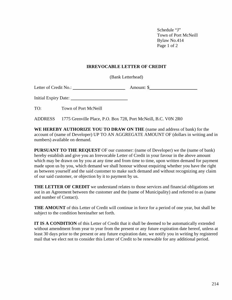
214
Schedule “J” Town of Port McNeill Bylaw No.414 Page 1 of 2
IRREVOCABLE LETTER OF CREDIT
(Bank Letterhead) Letter of Credit No.: _______________________ Amount: $_____________________ Initial Expiry Date: _________________________ TO: Town of Port McNeill ADDRESS 1775 Grenville Place, P.O. Box 728, Port McNeill, B.C. V0N 2R0 WE HEREBY AUTHORIZE YOU TO DRAW ON THE (name and address of bank) for the account of (name of Developer) UP TO AN AGGREGATE AMOUNT OF (dollars in writing and in numbers) available on demand. PURSUANT TO THE REQUEST OF our customer: (name of Developer) we the (name of bank) hereby establish and give you an Irrevocable Letter of Credit in your favour in the above amount which may be drawn on by you at any time and from time to time, upon written demand for payment made upon us by you, which demand we shall honour without enquiring whether you have the right as between yourself and the said customer to make such demand and without recognizing any claim of our said customer, or objection by it to payment by us. THE LETTER OF CREDIT we understand relates to those services and financial obligations set out in an Agreement between the customer and the (name of Municipality) and referred to as (name and number of Contact). THE AMOUNT of this Letter of Credit will continue in force for a period of one year, but shall be subject to the condition hereinafter set forth. IT IS A CONDITION of this Letter of Credit that it shall be deemed to be automatically extended without amendment from year to year from the present or any future expiration date hereof, unless at least 30 days prior to the present or any future expiration date, we notify you in writing by registered mail that we elect not to consider this Letter of Credit to be renewable for any additional period.
215
Schedule “J” Town of Port McNeill Bylaw No.414 Page 2 of 2
Dated at , British Columbia, this____day of _________, 19_____. COUNTERSIGNED BY:____________________________________ (name of Bank) ______________________________ per: _________________________________ _________________________________

216
Schedule “K” Town of Port McNeill Bylaw No.414 Page 1 of 3
WARRANTY AGREEMENT THIS AGREEMENT dated the ____ day of ___________________, 19______ BETWEEN: TOWN OF PORT MCNEILL 1775 Grenville Place P.O. Box 728 Port McNeill, B.C. V0N 2R0 (hereinafter referred to as the “Town”)
OF THE FIRST PART. AND: ____________________ ____________________ ____________________ ____________________ (hereinafter referred to as the “Owner”)
OF THE SECOND PART. WHEREAS. a. The Owner has entered into an agreement with the Town to provide works and services for a
subdivision or development of the lands described for the purpose of this agreement as: _____________________________________________ _____________________________________________ B. Before a plan of subdivision of the said lands will be approved by the Approving Officer of
the Town, or a building permit issued, the Owner must enter into an agreement with the Town to warranty the works and services constructed and installed or forfeit the amount secured by a bond to be deposited by the Owner with the Town.
NOW THEREFORE THIS AGREEMENT WITNESSETH that in consideration of the premises and the terms and conditions hereinafter contained, the parties hereto covenant and agree a follows:

217
Schedule “K” Town of Port McNeill Bylaw No.414 Page 2 of 3
1. In this agreement the term “the works and services” means those works and services shown
on design Drawings Nos.___________(name them), as approved by the Approving Officer of the Town, for the works and services shown on said drawing to be constructed and installed at the expense of the Owner.
2. The Town shall not assume responsibility for works and services installed under this
agreement until satisfactory “as-constructed” drawings are delivered to the Clerk by the Owner and a bond in the form of cash, certified cheque or letter of credit is deposited with the Clerk in the amount of five percent with a minimum of Five Hundred Dollars, whichever is the greater, of the estimated construction cost of the services as certified by the Owner, as a guarantee of faithful and diligent performance in rectifying any deficiencies in design, materials and workmanship that may arise in connection with the services during the twelve months next following the issuance of the Certificate of Completion in Schedule “B”.
3. Any deficiencies in design, materials or workmanship that may arise in connection with the
services during the twelve months next following the assumption of ownership of the works and services by the Town shall be rectified by the Owner at his own expense and to the satisfaction of the Clerk. If the Owner fails, after notice from the Town to rectify any such deficiencies to the satisfaction of the Clerk, the Town may rectify such deficiencies and pay the cost thereof out of the bond referred to in the preceding paragraph. If the cost of rectifying such deficiencies is greater than the amount of the bond, the Owner shall pay such excess amount to the Town. Where a deficiency arises in a functioning sanitary sewer, storm drain or water pipe or where a deficiency in a service creates a danger to the public, the Town may rectify the deficiency without giving prior notice to the Owner and pay the cost thereof out of the bond and charge the Owner for any excess cost.
4. Where a Letter of Credit, including an extension of a Letter of Credit, has an expiry date, the
Owner shall, by no later than one week prior to the expiry date, deliver to the Clerk a one-year extension of the Letter of Credit, in default of which the Clerk may, at his option draw the outstanding balance of funds secured by the Letter of Credit.
5. Where cash or a certified cheque is given, the Town shall deposit the cash or certified cheque
in an interest bearing account and will return seventy-five percent of any interest earned. Twenty five percent of any interest shall be retained by the Town for administrative costs.
6. Upon approval of the works and services at the end of the twelve month period, any unused
portion of the Letter of Credit will be released and/or any balance of cash deposits will be returned and this agreement will terminate.
7. This agreement shall be binding upon and shall enure to the benefit of the parties hereto and
their respective executors, administrators, successors and assigns.

218
Schedule “K” Town of Port McNeill Bylaw No.414 Page 3 of 3
8. The Owner agrees to indemnify and save harmless the Town from any claims, suits,
demands, actions, damages, costs, or expenses, arising out of any deficiencies in the design, materials, or workmanship of services installed by the Owner during the warranty period provided by this agreement.
IN WITNESS WHEREOF the parties hereto have executed this Agreement as of the date first written above. SIGNED, SEALED AND DELIVERED BY ) the Owner in the presence of: ) ____________________________________ ) ____________________________________ ) ____________________________________ ) ____________________________________ ) Occupation (For use where the Owner is an individual or partnership) THE COMMON SEAL OF THE OWNER ) was affixed in the presence of: ) ) _____________________________________ ) Title_________________________________ ) (SEAL) _____________________________________ ) Title_________________________________ ) (for use where the Owner is an incorporated company or society) THE CORPORATE SEAL OF THE TOWN OF ) PORT MCNEILL was hereunto affixed in the presence of) ) ______________________________________ ) Mayor ) ) ______________________________________ ) (SEAL) Clerk )
219
Schedule “L” Town of Port McNeill Bylaw No. 414 Page 1 of 3
THIS AGREEMENT made the _______ day of _______, 19____. BETWEEN:
(hereinafter called the “Grantor”) OF THE FIRST PART
AND: TOWN OF PORT MCNEILL P.O. Box 728 Port McNeill, B.C. V0N 2R0 (hereinafter called the “Grantee”) OF THE SECOND PART WHEREAS: A. The Statutory Right-of-Way hereinafter created is necessary for the operation and maintenance of the Grantee’s undertaking. B. The Grantor is the registered owner in fee simple of the Land described in Schedule “A”, (hereinafter referred to as “The Grantor’s Lands”). C. Plan , the Plan of Statutory Right-of-Way over Parts of the Grantor’s Lands, has been deposited in the Land Title Office at Victoria, British Columbia on the day of , 1995. The Plan was tendered under s. 113(2) of the Land Title Act and was authorized under s.214 of the Land Title Act, (hereinafter referred to as the “Plan”). NOW THIS AGREEMENT WITNESSETH: 1. In consideration of the sum of ONE ($1.00) DOLLAR of lawful money of Canada (receipt and sufficiency of which is hereby acknowledged), the Grantor hereby grants in perpetuity to the Grantee the right and easement for the Grantee, its servants, agents and all others the licensees of the Grantee:

220
Schedule “L” Town of Port McNeill Bylaw No. 414 Page 2 of 3
(a) to construct, excavate, trench, operate, maintain, remove, and replace
______(Insert “sewer”, “water”, or “drain”) pipes together with all necessary appurtenances thereto (herein called the “works”) in, under and upon that part of the Grantor’s Land shown outlined in heavy black on the Plan, and which part is herein call the “Statutory Right-of-Way”.
(b) To pass and repass over the Statutory Right-of-Way to clear, dig, remove and
backfill soil, and make trenches and excavations on the Statutory Right-of-Way for any of the purposes aforesaid.
2. The Grantor further grants to the Grantee, its servants, agents and all others the licencees of the Grantee, a licence:
(a) to pass and repass over and across the Grantor’s Lands with necessary tools and equipment for the purpose of ingress and egress to and from the Statutory Right-of-Way.
(b) During the initial period of construction only, to use such portion of the
Grantor’s Land alongside the Statutory Right-of-Way as may be reasonably necessary as an additional working area to facilitate the Grantee carrying out its work under the rights granted herein.
3. The Grantee covenants with the Grantor that it will, as soon as weather and soil conditions permit, and as often as it may exercise its right of entry hereunder to any of the Grantor’s Lands, restore the same as near as may be reasonably possible to the same condition as it was prior to such entry, provided however that nothing herein contained shall require the Grantee to restore any trees. 4. The Grantor hereby covenants with the Grantee:
(a) Not to make, place, erect or maintain, subsequent to the date hereof, any building, structure, excavation, pile of material or obstruction in, under or upon the Statutory Right-of-Way without the written consent of the Grantee first had and obtained.
(b) Not to do or knowingly permit to be done any act or thing which will interfere
with or injure the said works and in particular will not carry on any blasting on or adjacent to the Statutory Right-of-Way without the consent of the Grantee, provided that such consent shall not be unreasonably withheld.

221
Schedule “L” Town of Port McNeill Bylaw No. 414 Page 3of 3
(c) Not to substantially diminish the soil cover over any of the works in the Statutory Right-of-Way, and in particular without in any way limiting the generality of the foregoing, not to construct open drains or ditches along or across any of the works installed in the Statutory Right-of-Way without the consent of the Grantee, provided that such consent shall not be unreasonably withheld.
5. It is mutually agreed between the Grantor and the Grantee:
(a) That the Statutory Right-of-Way shall be construed as running with the land, that no part of the fee of the soil shall pass to or be vested in the Grantee under or by these presents and that the Grantor may use and enjoy the said land, subject only to the rights and restrictions herein provided.
(b) That the expressions “Grantor” and “Grantee” herein contained shall be
deemed to include the executors, administrators, successors and assigns of such parties wherever the context so admits.
(c) Wherever the singular or masculine are used in this Agreement they shall be
construed as meaning the plural or the feminine or the body corporate where the context or the parties hereto so require.
IN WITNESS WHERE OF the parties hereto have caused these presents to be executed as of the day and year first above written.
THE END