Towards Safer and More Reliable Sensor-enabled...
48
SAFECOM 2012, Magdeburg Sensing everywhere: Towards Safer and More Reliable Sensor-enabled Devices Marta Kwiatkowska University of Oxford
Transcript of Towards Safer and More Reliable Sensor-enabled...

SAFECOM 2012, Magdeburg
Sensing everywhere:
Towards Safer and More ReliableSensor-enabled Devices
Marta KwiatkowskaUniversity of Oxford
2
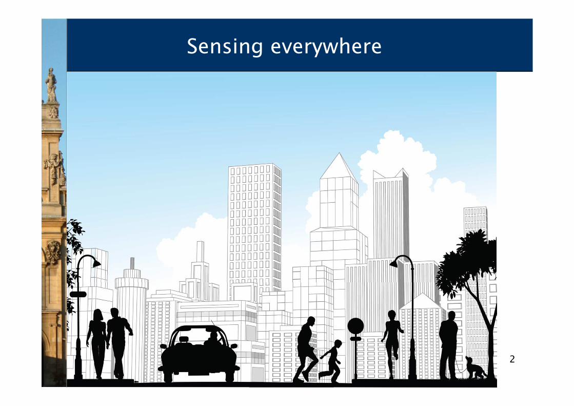
Sensing everywhere

3
Smartphones, tablets…
Sensor apps
GPS/GPRS trackingAccelerometerAir quality
Access to servicesPersonalised monitoring
4
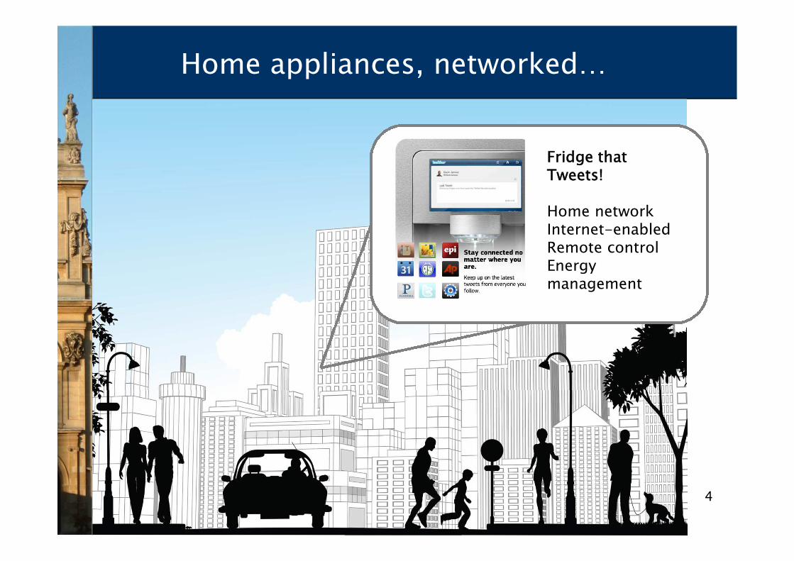
Home appliances, networked…
Fridge thatTweets!
Home networkInternet-enabledRemote controlEnergymanagement
5
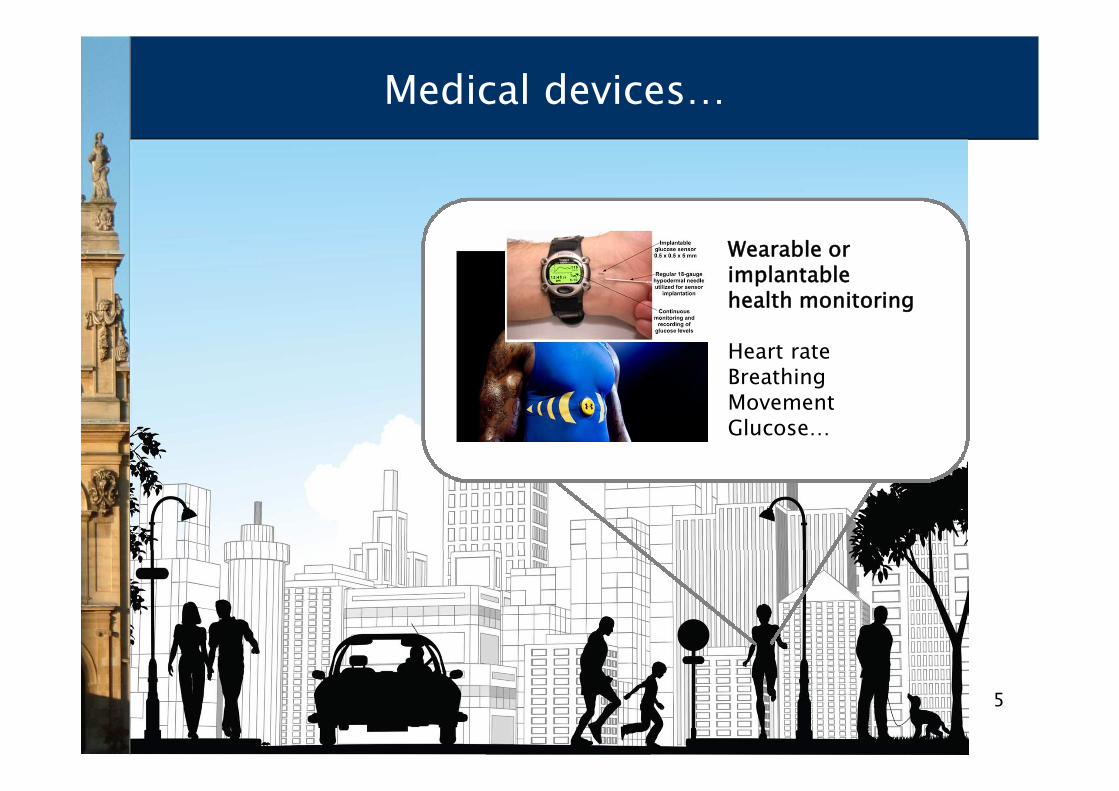
Medical devices…
Wearable orimplantablehealth monitoring
Heart rateBreathingMovementGlucose…

6
Ubiquitous computing
• (also known as Pervasive Computing or Internet of Things
− enabled by wireless technology and cloud computing)
• Populations of sensor-enabled computing devices that are
− embedded in the environment, or even in our body
− sensors for interaction and control of the environment
− software controlled, can communicate
− operate autonomously, unattended
− devices are mobile, handheld or wearable
− miniature size, limited resources, bandwidth and memory
• Unstoppable technological progress
− smaller and smaller devices, more and more complex scenarios…

77
Challenges
• Smart sensors and apps
− sensors are integral components of devices
− quantitative readings, not just binary
• Failure a tangible risk, in view of
− wireless connectivity
− mobility
− probabilistic modelling helpful
• Energy- and resource efficiency of growing importance
− battery-powered, small memory
− quantitative analysis needed
• and more…
• How to ensure correctness, safety, dependability, security,performability?
− complex scenarios, recovery from faults, resource usage, …

8
Safety-critical applications
• Consequences of failure may endanger life
− implantable medical devices, automotive components, avionics, biosensing, etc
• Software is a critical component
− failure of embedded software accounts for costly recalls
• Need quality assurance methodologies
− model-based development
− rigorous software engineering
− software product lines
• Focus on automated, tool-supported methodologies
− automated verification via model checking
− quantitative/probabilistic verification
9
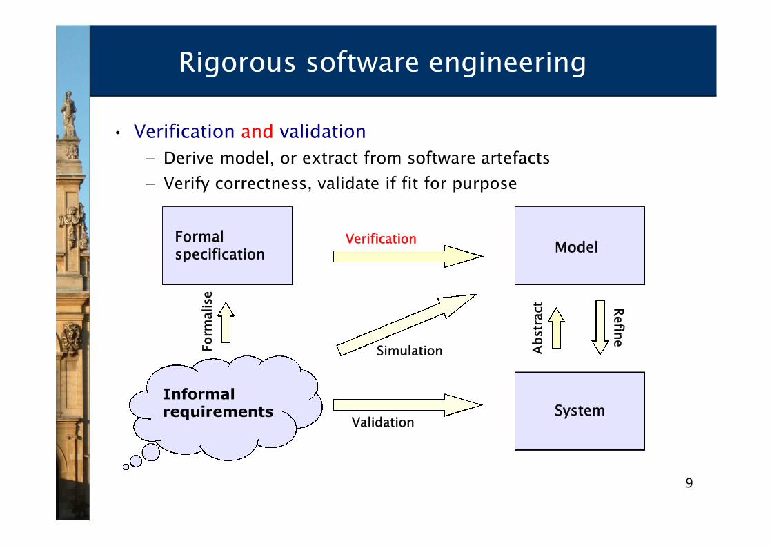
Rigorous software engineering
• Verification and validation
− Derive model, or extract from software artefacts
− Verify correctness, validate if fit for purpose
ModelFormalspecification
SystemValidation
Verification
Ab
str
act R
efin
e
Form
alise
Simulation
Informalrequirements

10
Towards certifiable sensor devices
• Standards (e.g. DO-178B for avionics) recommend model-based approaches
• Combine traditional safety assurance methodologies
− hazard analysis
− FTA, FMEA
− safety/dependability cases
• with formal verification techniques to automaticallyproduce guarantees for:
− safety, reliability, performance, resource usage, trust, …
− (safety) “probability of failure to raise alarm is tolerably low”
− (reliability) “the smartphone will never execute the financialtransaction twice”
• Probabilistic/quantitative verification necessary for safetyand dependability analysis

11
Rigorous safety development
• Base on SAML (Safety Analysis Modelling Language)
• Example of an airbagcomponent
Gudemann et al

12
Quantitative (probabilistic) verification
Probabilistic modele.g. Markov chain
Probabilistic temporallogic specificatione.g. PCTL, CSL, LTL
Result
Quantitativeresults
System
Counter-example
Systemrequire-ments
P<0.01 [ F≤t fail]
0.5
0.1
0.4
Probabilisticmodel checker
e.g. PRISM
Automatic verification (aka model checking) of quantitativeproperties of probabilistic system models

13
Why quantitative verification?
• Real ubicomp software/systems are quantitative:
− Real-time aspects
• hard/soft time deadlines
− Resource constraints
• energy, buffer size, number of unsuccessful transmissions, etc
− Randomisation, e.g. in distributed coordination algorithms
• random delays/back-off in Bluetooth, Zigbee
− Uncertainty, e.g. communication failures/delays
• prevalence of wireless communication
• Analysis “quantitative” & “exhaustive”
− strength of mathematical proof
− best/worst-case scenarios, notpossible with simulation
− identifying trends and anomalies

14
Quantitative properties
• Simple properties
− P≤0.01 [ F “fail” ] – “the probability of a failure is at most 0.01”
• Analysing best and worst case scenarios
− Pmax=? [ F≤10 “outage” ] – “worst-case probability of an outageoccurring within 10 seconds, for any possible scheduling ofsystem components”
− P=? [ G≤0.02 !“deploy” {“crash”}{max} ] - “the maximumprobability of an airbag failing to deploy within 0.02s,from any possible crash scenario”
• Reward/cost-based properties
− R{“time”}=? [ F “end” ] – “expected algorithm execution time”
− R{“energy”}max=? [ C≤7200 ] – “worst-case expected energyconsumption during the first 2 hours”

15
Historical perspective
• First algorithms proposed in 1980s
− [Vardi, Courcoubetis, Yannakakis, …]
− algorithms [Hansson, Jonsson, de Alfaro] & first implementations
• 2000: tools ETMCC (MRMC) & PRISM released
− PRISM: efficient extensions of symbolic model checking [Kwiatkowska, Norman, Parker, …]
− ETMCC (now MRMC): model checking for continuous-time Markov chains [Baier, Hermanns, Haverkort, Katoen, …]
• Now mature area, of industrial relevance
− successfully used by non-experts for many application domains, but full automation and good tool support essential
• distributed algorithms, communication protocols, security protocols,biological systems, quantum cryptography, planning…
− genuine flaws found and corrected in real-world systems
16
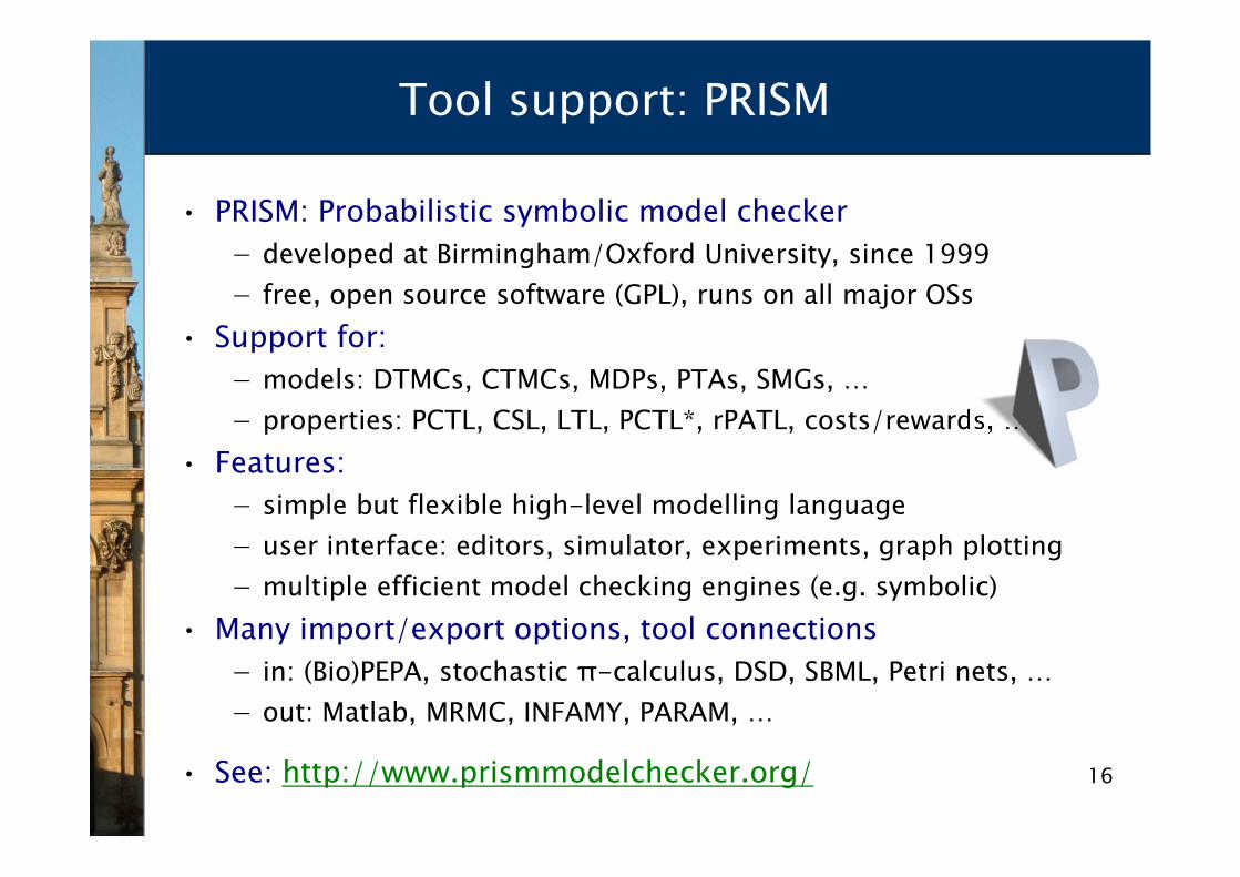
Tool support: PRISM
• PRISM: Probabilistic symbolic model checker
− developed at Birmingham/Oxford University, since 1999
− free, open source software (GPL), runs on all major OSs
• Support for:
− models: DTMCs, CTMCs, MDPs, PTAs, SMGs, …
− properties: PCTL, CSL, LTL, PCTL*, rPATL, costs/rewards, …
• Features:
− simple but flexible high-level modelling language
− user interface: editors, simulator, experiments, graph plotting
− multiple efficient model checking engines (e.g. symbolic)
• Many import/export options, tool connections
− in: (Bio)PEPA, stochastic π-calculus, DSD, SBML, Petri nets, …
− out: Matlab, MRMC, INFAMY, PARAM, …
• See: http://www.prismmodelchecker.org/

1717
Probabilistic model checking involves…
• Construction of models
− from a high-level modelling language
− e.g. probabilistic process algebra
• Implementation of probabilistic model checking algorithms
− graph-theoretical algorithms, combined with
• (probabilistic) reachability
− numerical computation – iterative methods
• quantitative model checking (plot values for a range ofparameters)
• typically, linear equation or linear optimisation
• exhaustive, unlike simulation
− also sampling-based (statistical) for approximate analysis
• e.g. hypothesis testing based on simulation runs

1818
Model derivation techniques
• Models are typically state-transition systems (automata)
• Manual construction
− derive a model from description
• e.g. IEEE standards document
− express in high-level language, then build
• Automated extraction
− extract a model from software
• using e.g. abstract interpretation, slicing, static analysis…
− build a data structure
• Challenges
− state space explosion, infinite state systems
− need to consider augmenting with additional information
• action labels, state labels, time, probability, rate, etc
Model

19
Quantitative verification in action
• Bluetooth device discovery protocol
− frequency hopping, randomised delays
− low-level model in PRISM, based ondetailed Bluetooth referencedocumentation
− numerical solution of 32 Markov chains,each approximately 3 billion states
• Bluetooth time to hear one reply
− Worst-case expected time = 2.5716s
− in 921,600 possible initial states
− Best-case expected time = 635μs
• Bluetooth time to hear two replies
− Worst-case expected time = 5.177s
− in 444 possible initial states

20
Current directions
• Recent advances in (quantitative) verification for sensor-based devices
• Implantable medical devices
− cardiac pacemaker study
• Nanoscale computing and biosensing
− DNA computation and self-assembly
• Software verification for sensor networks
− TinyOS
• Brief overview of the above directions
− each demonstrating transition from theory to practice
− formulating novel verification algorithms
− resulting in new software tools
21
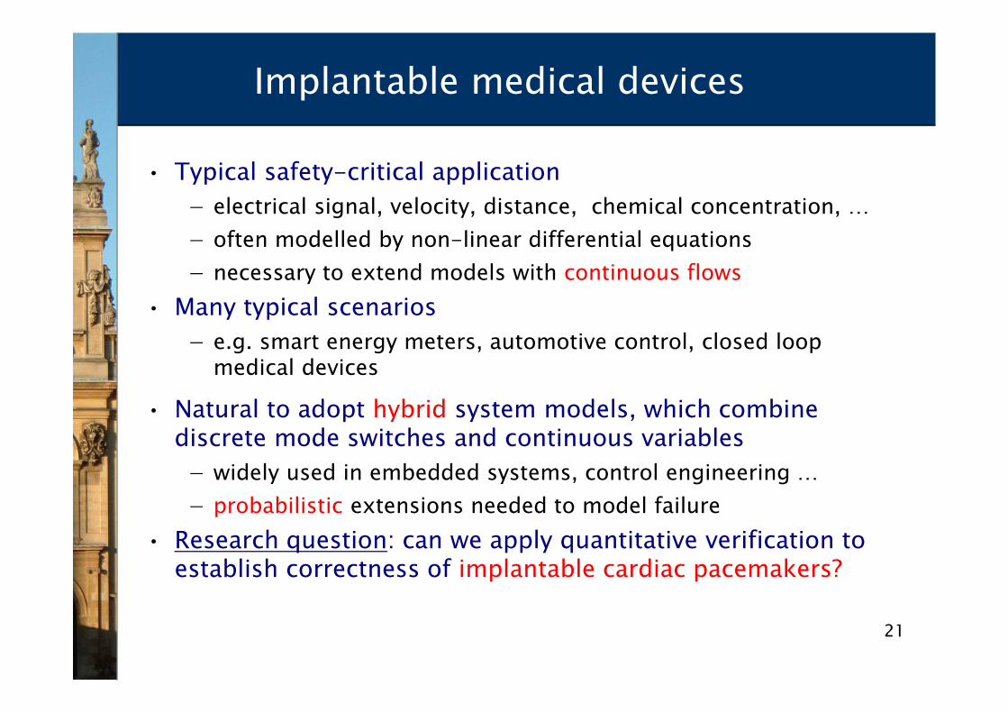
Implantable medical devices
• Typical safety-critical application
− electrical signal, velocity, distance, chemical concentration, …
− often modelled by non-linear differential equations
− necessary to extend models with continuous flows
• Many typical scenarios
− e.g. smart energy meters, automotive control, closed loop medical devices
• Natural to adopt hybrid system models, which combinediscrete mode switches and continuous variables
− widely used in embedded systems, control engineering …
− probabilistic extensions needed to model failure
• Research question: can we apply quantitative verification toestablish correctness of implantable cardiac pacemakers?

22
Function of the heart
• Maintains blood circulation by contracting the atria andventricles
− spontaneously generates electrical signal (action potential)
− conducted through cellular pathways into atrium, causing contraction of atria then ventricles
− repeats, maintaining 60-100 beats per minute
− a real-time system, and natural pacemaker
• Abnormalities inelectricalconduction
− missed/slow heart beat
− can be corrected by by implantablepacemakers

23
Implantable pacemaker
• How it works
− reads electrical (action potential) signals through sensorsplaced in the right atrium and right ventricle
− monitors the timing of heart beatsand local electrical activity
− generates artificial pacing signalas necessary
• Embedded software
• Widely used, replacedevery few years
• Unfortunately…
− 600,000 devices recalled during 1990-2000
− 200,000 due to firmware problems
24
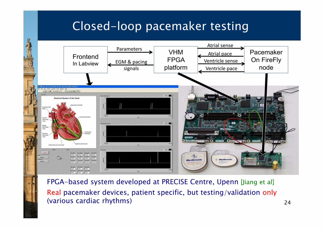
Closed-loop pacemaker testing
FPGA-based system developed at PRECISE Centre, Upenn [Jiang et al]
Real pacemaker devices, patient specific, but testing/validation only(various cardiac rhythms)
25
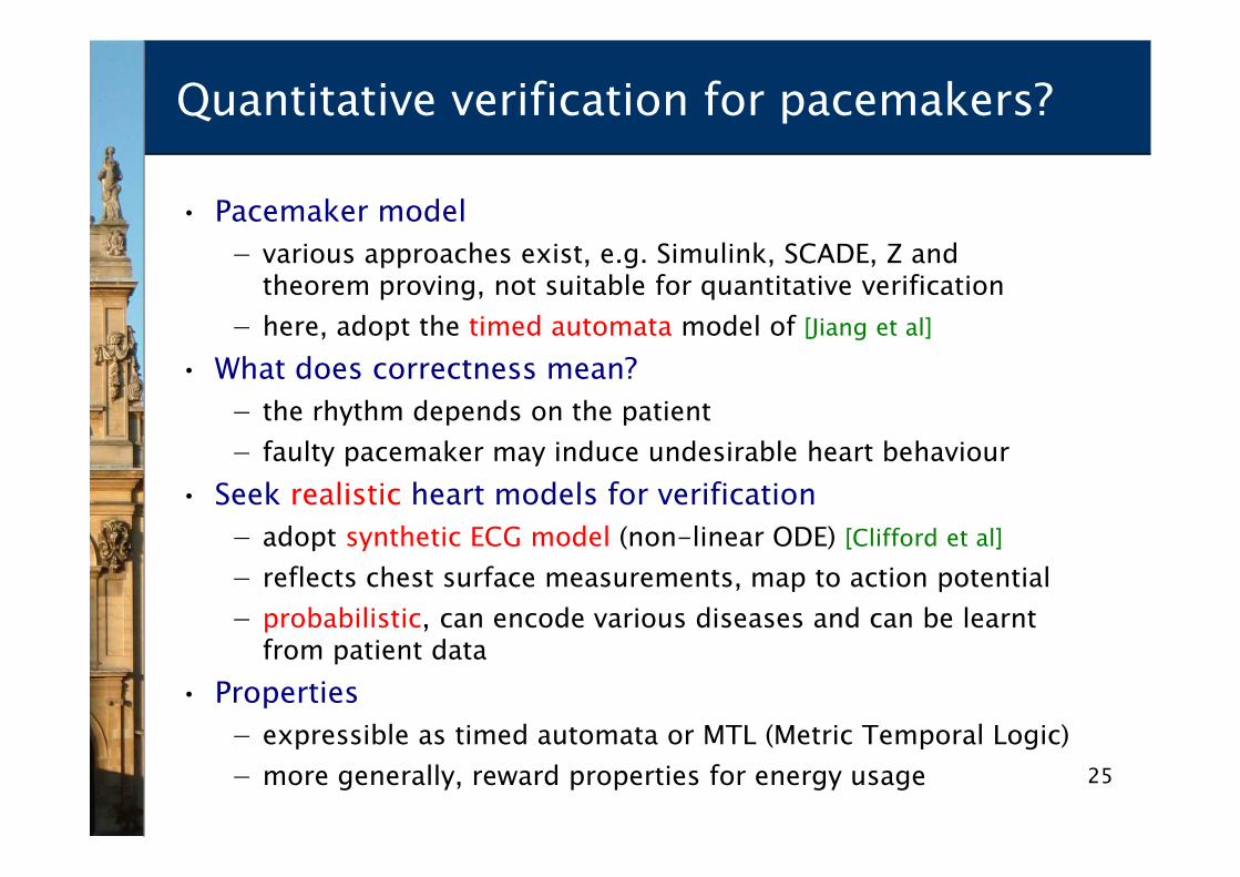
Quantitative verification for pacemakers?
• Pacemaker model
− various approaches exist, e.g. Simulink, SCADE, Z and theorem proving, not suitable for quantitative verification
− here, adopt the timed automata model of [Jiang et al]
• What does correctness mean?
− the rhythm depends on the patient
− faulty pacemaker may induce undesirable heart behaviour
• Seek realistic heart models for verification
− adopt synthetic ECG model (non-linear ODE) [Clifford et al]
− reflects chest surface measurements, map to action potential
− probabilistic, can encode various diseases and can be learntfrom patient data
• Properties
− expressible as timed automata or MTL (Metric Temporal Logic)
− more generally, reward properties for energy usage

26
Quantitative verification for pacemakers
• Model the pacemaker and the heart, compose and verify

27
Quantitative verification for pacemakers

28
Quantitative verification for pacemakers
29
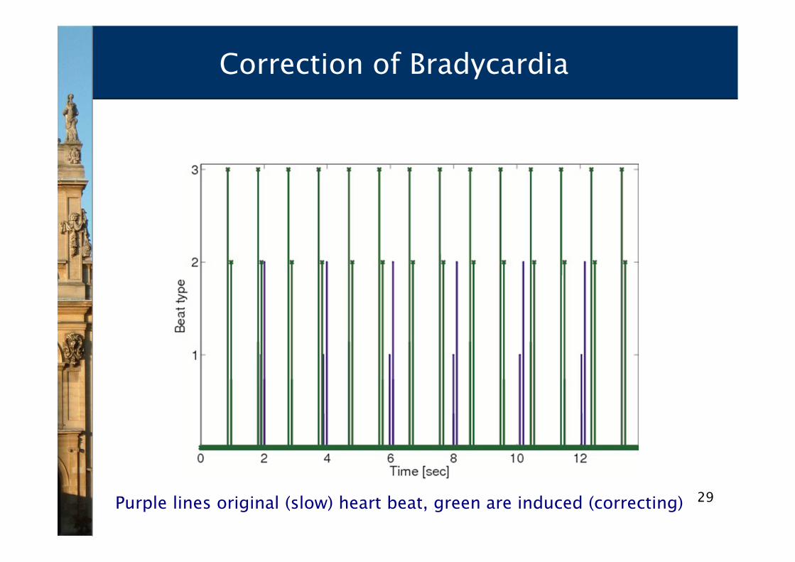
Correction of Bradycardia
Purple lines original (slow) heart beat, green are induced (correcting)

30
Faulty pacemaker inducing Tachycardia
Purple lines are normal, green lines are induced (too fast)
31
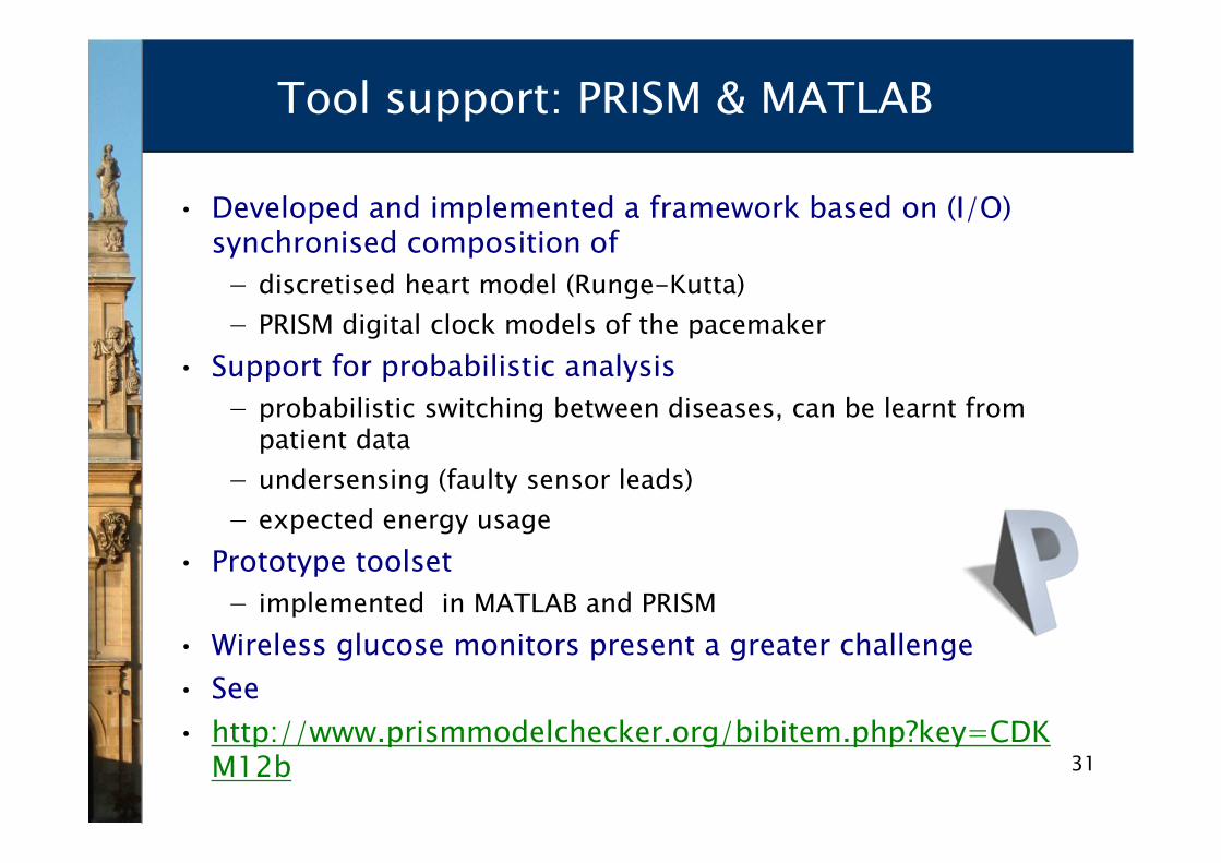
Tool support: PRISM & MATLAB
• Developed and implemented a framework based on (I/O)synchronised composition of
− discretised heart model (Runge-Kutta)
− PRISM digital clock models of the pacemaker
• Support for probabilistic analysis
− probabilistic switching between diseases, can be learnt from patient data
− undersensing (faulty sensor leads)
− expected energy usage
• Prototype toolset
− implemented in MATLAB and PRISM
• Wireless glucose monitors present a greater challenge
• See
• http://www.prismmodelchecker.org/bibitem.php?key=CDKM12b

32
Nanoscale computing and biosensing
• The molecular programming approach
− aim to devise programmable mechanisms directly at themolecular level
− DNA computing devices
− e.g., DNA origami pliers to detect presence of a target molecule
− product families, e.g. DNA tweezers
• Many safety-critical applications
− e.g. drug delivery directly into the blood stream, implantable continuous monitoring devices
• First approaches towards rigorous safety analysis
− goal-oriented requirements modelling and analysis of theDNA pliers
− based on van Lamsweerde (2009 ) and using PRISM [Lutz et al, ICSE 2012, RE 2012]

33
Digital circuits
• Logic gates realised in silicon
• 0s and 1s are represented as low and high voltage
• Hardware verification indispensable as design methodology

34
DNA programming
2nm
DNA origami
• “Computing with soup” (The Economist 2012)
− DNA strands are mixed together in a test tube
− single strands are inputs and outputs
− computation proceeds autonomously
• Can we transfer verification to this new application domain?
− stochasticity essential!

35
DNA circuits
Pop quiz, hotshot: what'sthe square root of 13?Science Photo Library/Alamy
[Qian, Winfree,Science 2012]
• Techniques exist for designingDNA circuits
• (DNA Strand Displacement)
• Circuit of 130 strands computessquare root of 4 bit number,rounded down
• 10 hours, but it’s a first…

36
DNA Strand Displacement
• Design (simplified) logic gates in DNA
− double strands with nicks (interruptions) in the top strand
− and single strands consisting of one (short) toehold domain t and one recognition domain x
− “toehold exchange”: branch migration of strand <t^ x> leading to displacement of strand <x t^>
• DSD process algebra semantics due to Cardelli
• DSD programming environment due to Phillips (Microsoft)
[Cardelli’10] Two-Domain DNA Strand Displacement. DCM’10

37
Example: Transducer
• Transducer: converts input <t^ x> into output <t^ y>

38
Example: Transducer
• Transducer: full reaction list
input outputunreactive structures(no exposed toeholds)
39
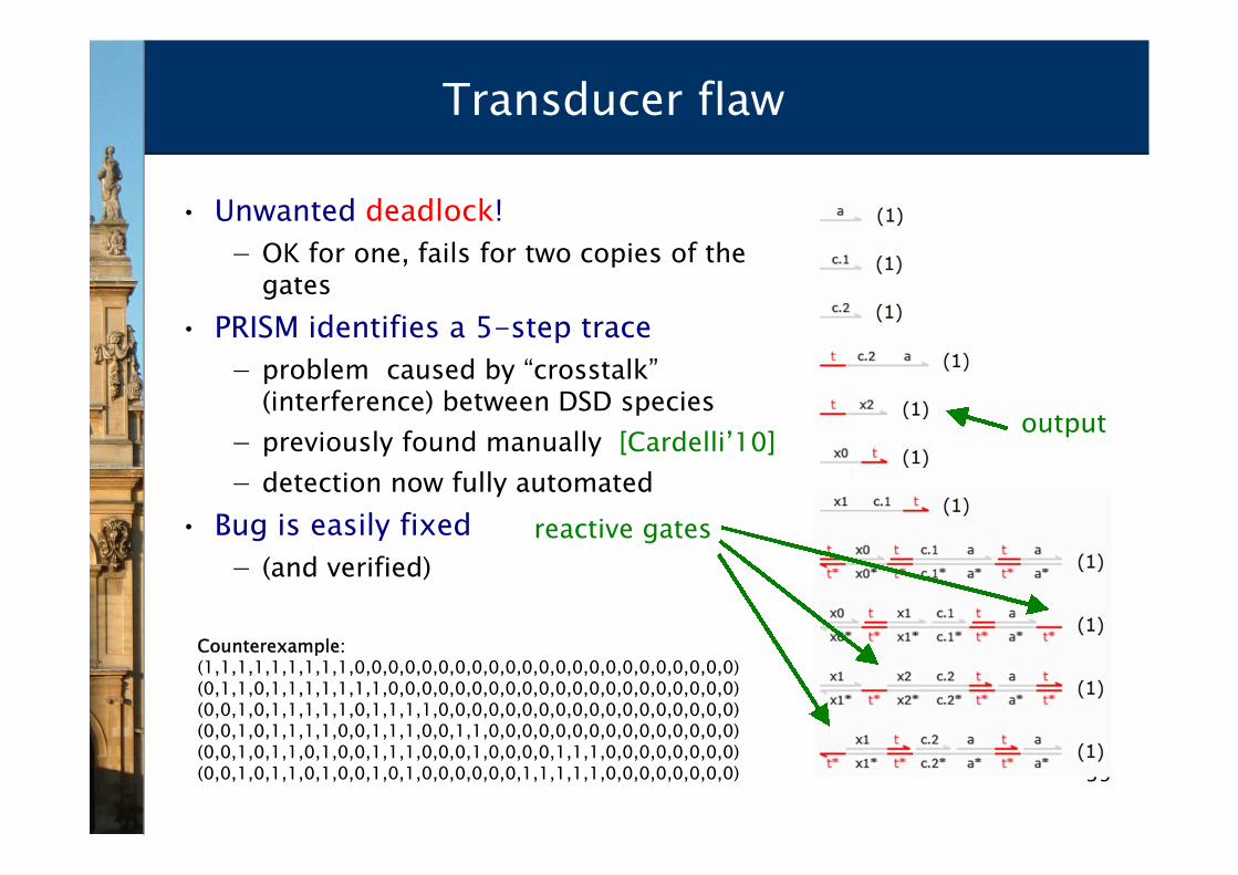
Transducer flaw
• Unwanted deadlock!
− OK for one, fails for two copies of the gates
• PRISM identifies a 5-step trace
− problem caused by “crosstalk”(interference) between DSD species
− previously found manually [Cardelli’10]
− detection now fully automated
• Bug is easily fixed
− (and verified)
Counterexample:(1,1,1,1,1,1,1,1,1,0,0,0,0,0,0,0,0,0,0,0,0,0,0,0,0,0,0,0,0,0,0,0)(0,1,1,0,1,1,1,1,1,1,1,0,0,0,0,0,0,0,0,0,0,0,0,0,0,0,0,0,0,0,0,0)(0,0,1,0,1,1,1,1,1,0,1,1,1,1,0,0,0,0,0,0,0,0,0,0,0,0,0,0,0,0,0,0)(0,0,1,0,1,1,1,1,0,0,1,1,1,0,0,1,1,0,0,0,0,0,0,0,0,0,0,0,0,0,0,0)(0,0,1,0,1,1,0,1,0,0,1,1,1,0,0,0,1,0,0,0,0,1,1,1,0,0,0,0,0,0,0,0)(0,0,1,0,1,1,0,1,0,0,1,0,1,0,0,0,0,0,0,1,1,1,1,1,0,0,0,0,0,0,0,0)
reactive gates
output
40
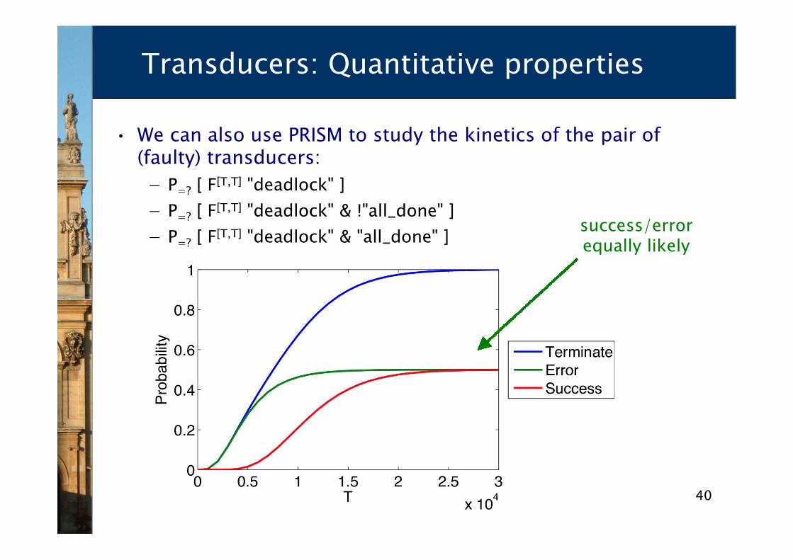
Transducers: Quantitative properties
• We can also use PRISM to study the kinetics of the pair of(faulty) transducers:
− P=? [ F[T,T] "deadlock" ]
− P=? [ F[T,T] "deadlock" & !"all_done" ]
− P=? [ F[T,T] "deadlock" & "all_done" ]success/errorequally likely
41
Tool support: DSD & PRISM
• Developed a framework incorporating DSD and PRISM
− DSD designs automatically translated to PRISM via SBML
• Model checking as for molecular signalling networks
− reduction to CTMC model
− reuse existing PRISM algorithms
• Achievements
− first ever (quantitative) verification of a DNA circuit
− demonstrated bugs can be found automatically
− but scalability major challenge, can only deal with small designs
• Further case studies
− Approximate Majority population protocol
• Available now:
http://research.microsoft.com/en-us/projects/dna/
42
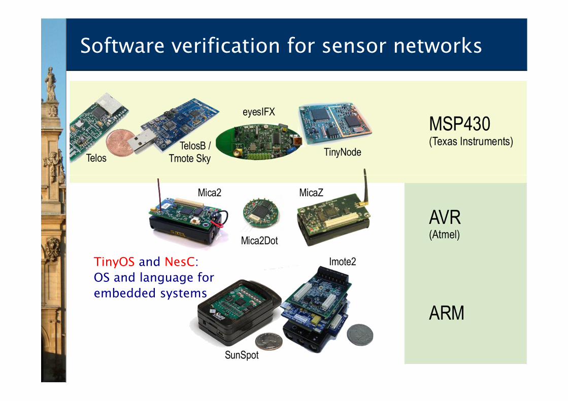
Software verification for sensor networks
TinyOS and NesC:
OS and language for
embedded systems

43
A TinyOS application
Threads, so concurrency
Interrupts

44
...and TinyOS’s compile stages
Platform dependency!

45
Tool support for TinyOS
• Use software verification via model checking
− extract model automatically, via translation of NesC to C
• Two approaches
− precise model of application, assumptions on the behaviour ofthe platform
− preserve system-wide code (including the kernel), model themicrocontroller’s working:
• memory map, interrupt system
• not quantitative, yet…
• Progress with “bounded” verification
− few IRQ calls, little recursion unwinding (CBMC)
− specifications asassertions upon program states
• Encouraging results – model checks in a few sec/minutes!
• Uses CProver tools by Daniel Kroening, see
http://code.google.com/p/tos2cprover/

46
Summing up…
• Brief overview of three directions aimed at improving thesafety and reliability of sensor-based devices
− demonstrated some successes and usefulness of quantitativeverification methodology
− new techniques and tools
• Many challenges remain
− incorporation of quantitative verification in pacemaker development environments
− real industrial case studies
− certification and code generation for medical devices
− scalability of verification for molecular programming models
• More challenges not covered in this lecture
− integrated environments, safety and dependability applications, automated synthesis, …

47
References
• Pacemaker
− T. Chen, M. Diciolla, M. Kwiatkowska and A. Mereacre. Quantitative Verification of Implantable Cardiac Pacemakers. RTSS 2012.
− See also Jiang et al: Modeling and Verification of a Dual Chamber Implantable Pacemaker. TACAS 2012: 188-203.
• DNA programming
− M. Lakin, D. Parker, L. Cardelli, M. Kwiatkowska and A. Phillips. Design and Analysis of DNA Strand Displacement Devices using ProbabilisticModel Checking. J R Soc Interface, 9(72), 1470-1485, 2012.
• TinyOS
− D. Bucur, M. Kwiatkowska: On software verification for sensor nodes. Journal of Systems and Software 84(10): 1693-1707 (2011).
• See also
− M. Kwiatkowska, G. Norman and D. Parker. PRISM 4.0: Verification of Probabilistic Real-time Systems. CAV 2011: 585-591.
48
Acknowledgements
• My group and collaborators in this work
− Doina Bucur, Luca Cardelli, Taolue Chen, Marco Diciolla, Matthew Lakin, Alexandru Mereacre, Gethin Norman, DaveParker, Andrew Phillips
• Collaborators who contributed to theoretical and practicalPRISM development
• External users of and contributors to PRISM
• Project funding
− ERC, EPSRC
− Oxford Martin School, Institute for the Future of Computing
• See also
− www.veriware.org
− PRISM www.prismmodelchecker.org