Towards a General Framework for Modeling, Simulating...
12
Towards a General Framework for Modeling, Simulating and Building Sensor/Actuator Systems and Robots for the Web of Things Ion Mircea Diaconescu 1 and Gerd Wagner 1 1 Chair of Internet Technology Institute of Informatics Brandenburg University of Technology, Germany {M.Diaconescu, G.Wagner}@b-tu.de Abstract. The Web of Things (WoT) refers to those parts of the web consisting of special web application systems connected to the real world via sensors or actuators. These WoT systems include robots connected to the web as a special case. We propose a general framework for model- ing, simulating, designing and building WoT systems. We propose a core ontology for WoT systems, which is the basis for our modeling and sim- ulation approach. The modeling and simulation part of our framework is independent of the WoT and could also be employed in the engineering of other forms of embedded systems and robots. As a test case and a proof of concept we present an example of a green house WoT system. Keywords: Web of Things · sensors · actuators · robots · ontology · modeling · simulation. 1 Introduction The Web of Things (WoT ) is a subset of the Internet of Things (IoT ). While in the IoT, all kinds of Internet technologies can be used for building sensor-based information systems and device control applications, the WoT is based on web technologies only: foremost DNS, HTTP and HTTP-compatible protocols like Web Sockets and the Constrained Application Protocol (CoAP), and the user interface and frontend computing technologies HTML, CSS and JavaScript. The WoT consists of special web application systems connected to the real world via sensors or actuators, including robots connected to the web as a special case. There are three recent trends promoting the WoT. First, the web’s infrastruc- ture has progressed dramatically 1) by extending the internet’s address space with IPV6, 2) by continuously increasing the speed and bandwidth of inter- net connections, and 3) by improving the speed of HTTP with HTTP 2.0 as well as introducing near-real-time web protocols like Web Sockets. Second, the widespread use of smartphones and tablets, containing various sensors, has cre- ated a large pool of sensing and computing resources for the WoT. Third, the
Transcript of Towards a General Framework for Modeling, Simulating...
Towards a General Framework for Modeling,Simulating and Building Sensor/ActuatorSystems and Robots for the Web of Things
Ion Mircea Diaconescu1 and Gerd Wagner1
1Chair of Internet TechnologyInstitute of Informatics
Brandenburg University of Technology, Germany{M.Diaconescu, G.Wagner}@b-tu.de
Abstract. The Web of Things (WoT) refers to those parts of the webconsisting of special web application systems connected to the real worldvia sensors or actuators. These WoT systems include robots connectedto the web as a special case. We propose a general framework for model-ing, simulating, designing and building WoT systems. We propose a coreontology for WoT systems, which is the basis for our modeling and sim-ulation approach. The modeling and simulation part of our framework isindependent of the WoT and could also be employed in the engineeringof other forms of embedded systems and robots. As a test case and aproof of concept we present an example of a green house WoT system.
Keywords: Web of Things · sensors · actuators · robots · ontology · modeling· simulation.
1 Introduction
The Web of Things (WoT ) is a subset of the Internet of Things (IoT ). While inthe IoT, all kinds of Internet technologies can be used for building sensor-basedinformation systems and device control applications, the WoT is based on webtechnologies only: foremost DNS, HTTP and HTTP-compatible protocols likeWeb Sockets and the Constrained Application Protocol (CoAP), and the userinterface and frontend computing technologies HTML, CSS and JavaScript. TheWoT consists of special web application systems connected to the real world viasensors or actuators, including robots connected to the web as a special case.
There are three recent trends promoting the WoT. First, the web’s infrastruc-ture has progressed dramatically 1) by extending the internet’s address spacewith IPV6, 2) by continuously increasing the speed and bandwidth of inter-net connections, and 3) by improving the speed of HTTP with HTTP 2.0 aswell as introducing near-real-time web protocols like Web Sockets. Second, thewidespread use of smartphones and tablets, containing various sensors, has cre-ated a large pool of sensing and computing resources for the WoT. Third, the

name[0..1] : String
Entity
PhysicalAgent
EventPhysicalObject MessageObject
participants
* *
CommunicationEvent
*
1
Agent
InMessageEvent
1
OutMessageEvent
1
receiver
1
*
sender1
*
ReactiveBehavior
*
1
Fig. 1. Top-level concepts of WoTCO
increasing availability of many kinds of cheap sensors, actuators and other elec-tronics components has led to the development of a large Do It Yourself (DIY)robotics and WoT community, creating lots of open source software and hard-ware, and publishing a great variety of DIY projects1. The availability of all theseresources, and, in particular, of low-cost hardware, creates new opportunities forWoT and robotics-related research and education.
For instance, a simple WoT project can be the temperature monitoring of aroom by using a cheap temperature sensor, like the Texas Instruments LM352
(available for about 1 Euro), attached to a Raspberry Pi microcomputer (avail-able for about 30 Euro) running a NodeJS-based web application on top of Linuxand connected to the Internet via WiFi. More complex WoT systems, like a homesecurity and monitoring system or a home robot that is able to move aroundand talk to people, can be built with hardware costs of a few hundreds Euro,only, possibly using a no-longer-needed smartphone as the control computer andexploiting its (GSM/3G and WiFi) communication and its (GPS, microphone,camera) sensing capabilities.
A critical issue for any kind of web application, and even more for devicecontrol applications in the WoT, is security. However, in this paper we do nottreat security issues.
In the robotics and WoT research literature, as well as in the DIY roboticsand WoT literature, there is still a lack of methodologies, including general ap-proaches to modeling and simulation. Our aim is to develop a general frameworkfor modeling, simulating, designing and building WoT systems (WoTS). The ba-sis of this framework is a WoTS core ontology defining such concepts as event,object, agent, sensor, actuator, etc.
1 See, e.g., http://www.instructables.com/tag/type-id/category-technology/.2 Centigrade Temperature Sensor: http://www.ti.com/lit/ds/symlink/lm35.pdf
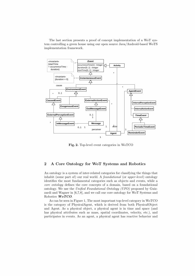
The last section presents a proof of concept implementation of a WoT sys-tem controlling a green house using our open source Java/Android-based WoTSimplementation framework.
occurrenceTime[1] : Integerduration[0..1] : IntegerstartTime[0..1] : Integer
Event
EnvironmentEventAgentEvent
InstantaneousEvent
ExogenousEvent
CausedEvent
*
cause
0..1
ExternalActionEvent
ExternalPerceptionEvent
InMessageEvent
OutMessageEvent
Message
0..11
0..1 1 PeriodicTimeEvent
TimeEvent
ReminderEventAgent
*
perceiver
1
*
actor1
*
1
InternalPerceptionEvent
Activity
*
1
«invariant»{startTime = occurrenceTime - duration}
«invariant»{duration = 0}
InternalActionEvent
Fig. 2. Top-level event categories in WoTCO
2 A Core Ontology for WoT Systems and Robotics
An ontology is a system of inter-related categories for classifying the things thatinhabit (some part of) our real world. A foundational (or upper-level) ontologyidentifies the most fundamental categories such as objects and events, while acore ontology defines the core concepts of a domain, based on a foundationalontology. We use the Unified Foundational Ontology (UFO) proposed by Guiz-zardi and Wagner in [6,7,8], and we call our core ontology for WoT Systems andRobotics WoTCO.
As can be seen in Figure 1, The most important top-level category in WoTCOis the category of PhysicalAgent, which is derived from both PhysicalObjectand Agent. As a physical object, a physical agent is in time and space (andhas physical attributes such as mass, spatial coordinates, velocity, etc.), andparticipates in events. As an agent, a physical agent has reactive behavior and

may participate in out-message events as sender, and in in-message events asreceiver.
As defined in Figure 3, a WoT system is a physical agent. A WoTS componentmay be a sensor, an actuator or a human-interface device (HID).
Actuator
Hid
WoTSystem
Sensor
WotsComponent
1*
1 *
WebRobot«invariant»{Components contain at least one sensor coupled to at least one actuator.}
PhysicalAgent
Fig. 3. WoTS components as physical agents
As defined in Figure 2 and 4, we distinguish between environment events,which occur in (and are used for simulating) the environment, and agent events,which occur internally in agents. Our high-level view of the perception-actioncycle of a WoTS can be described in WoTCO terms as follows. An external per-ception event, as an environment event, corresponds to a potential perceptionevent enabled by physical causality. A sensor of a WoTS maps such an externalperception event to an internal perception event (or sensor event). Then a reac-tive behavior rule maps this sensor event to an internal action event (or actuatorcommand), which is mapped to an external action event via the used actuator.The newly created external action event can then cause another external per-ception event, which starts the cycle over again.
3 Related Work
The IoT-A project has collected a report on the existing frameworks and archi-tectures [1] providing an overview of the current state of the art, and has definedan architectural reference model[2], which is very generic.
The issues of searchability, shareability and composability of WoT systemsare discussed in [3].
An attempt to define a core ontology for robotics based on the foundationalontology SUMO is made by the IEEE working group Ontologies for Roboticsand Automation (ORA) in [9]. Remarkably, this ontology does not include anyspecific concepts for sensors and actuators, which are subsumed under ”RobotPart”. Many top-level concepts of the ORA ontology are similar to our WoTCOcategories, but WoTCO is much more complete.

Sensor
1
outputs
*
Actuator
1
inputs
*
*
inputs
*
InternalPerceptionEvent
ExternalPerceptionEvent
*
cause
0..1
ExternalActionEvent
EnvironmentEvent
*resultingEvent*
InternalActionEvent
1
outputs
*
Fig. 4. Sensor/actuator events
4 An Architecture for WoTS and WoTS Simulations
Our goal is to develop a general architecture for modeling, simulating, designingand implementing WoT systems. This means that a WoTS model specifes bothboth the WoT system to be realized and its simulations, which may be partial inthe sense that any number of its components may be present in its configurationwhile all others are simulated.
4.1 Simulating WoTS Components
Our prototype WoT system presented in the next section is based on the archi-tecture metamodel shown in Figure 5, which is derived from the Agent-Object-Relationship Simulation Metamodel[4,5]. The central concept of this metamodelis WoTSComponent, which represents entities that have physical properties (e.g.,position, size, speed, etc) and whose reactive behaviors can be described byreaction rules triggered by events. For instance, a motor controller starts itsactivity when an internal action event ”GO” occurs. As shown in Figure 5, aWoTSComponent can be simultaneously an event source and an event listener.
A component can be atomic (a Sensor, an Actuator or a Hid) or composite,like, for example, a robot arm composed of a set of interconnected sensors andactuators. Even sensors can be composite devices, as for example a humidityand temperature sensor in a single unit with a single communication interface.
A WoTComponent (sensor, actuator, HID) or WoTSystem can contain a set ofcustom defined rules. The rule definition specifies the type of the event whichactivate it. The project author is free to build simple or complex rules by usingthe capabilities of the used system implementation programming language.

WoTSComponent
Event
occurrenceTime[1] : Datepriority[1] : EventPriorityduration[0..1] : Integer
«enumeration»EventPriority
VERY_HIGHHIGHMEDIUMLOWVERY_LOWReactionRule
1 *
addListener(in linstener : WoTSComponent)trigger(in listener : Event)
«interface»EventSource
on(in event : Event)
«interface»EventListener
*
source0..1
Fig. 5. General architecture model
Also the behavior of a WoT system is defined by reaction rules (e.g., triggerthe alarm when an intruder is detected or start watering the flowers when thesoil moisture is under a threshold value).
4.2 Sensors
Sensors are mostly used to collect data. In general a sensor can be an atomic com-ponent, having just one specific function (e.g., a LM35 centigrade temperaturesensor) or a composite one, where multiple sensors are packed in one unit andall of them use the same communication interface (e.g., 1-wire DHT22 temper-ature and humidity sensor). Sensors can be divided in categories based on theirtypes. Our category divisions (see Figure 6) were obtained by selecting the mostrelevant types of sensors, according to [11]. In some cases, one category may befurther divided, as for example in the case of WeatherSensor category, we have:TemperatureSensor, HumiditySensor, MoistureSensor, BarometerSensor andso on. For each sensor category (or sub-category) a related builtin event type,or set of event types are defined. The events are forwarded to the registeredlisteners, responsible to evaluate and use the sensor data by using their rules.
4.3 Actuators
Actuators are in general simple electro-mechanical devices that require a signal(voltage, current or a specific protocols) to activate or deactivate them. Themost relevant categories, according to [10], are captured in our model, as shownin Figure 7.
4.4 Human Interface Devices
According to [12], Human Interface Devices (HIDs), represent a special type ofWoT Components, and their main purpose is to provide an interface between the

ProximitySensor
WeatherSensor
ChemicalSensor
AcousticSensor
ElectricSensor
NavigationSensor
FluidFlow
OpticalSensor
RadiationSensor
MagneticSensor
RadioSensor
PositionSensor
ForceSensorSensortemperature : Double
TemperatureSensor
LM35
moisture : Double
SoilMoistureSensor
resistance : Double
ResistiveSoilMoistureSensor
getLuxValue() : Double
resistance : Double
PhotoResistorSensor
VT93N1
Fig. 6. Sensors architecture model
Actuator
HydraulicActuatorPneumaticActuatorElectricActuator
Motor Electrovalve Relay
ActuatorStateChangeEvent
* 1
state : Boolean
PullDownRelayActuator
frequency : DoubledutyCycle : Double
PWMController
Fig. 7. Actuators architecture model

system and a human user who needs to interact with the system. Such devices caneither be input or output devices, but can also be composite devices (providingmultiple inputs, multiple outputs or multiple inputs and outputs). Examples ofHIDs are displays (with or without touch screen), LEDs, keyboards, etc.
5 Test Case: The Green House Project
This section presents a project as a proof of concept for the proposed archi-tecture. The project is about the implementation of a Green House, which ismonitored and controlled by a WoT System. Specific needs in terms of temper-ature, water and light have to be considered for the Green House. The systemprovides the following functionality:
– soil moisture sensors measure from dry up to flooded soil.– the temperature is monitored and an automatic cooling system is activated
to control the temperature (air flux may come from outdoors).– a specific light intensity is required for an optimal production.– the water system can be started or stopped by using an electrovalve.
Figure 8 shows the model instance of the Green House project, according withthe architecture model discussed in this paper.
GreenHouse : component::WoTSystem
tempSensor : temperature::LM35
moistureSensor : moisture::ResistiveSoilMoistureSensor
photoResistorSensor : optical::VT93N1
waterValveRelay : electric::PullDownRelayActuator
coolerRelay : electric::PullDownRelayActuator lightPWMController : electric::PWMController
Fig. 8. Green House test case model instance
5.1 Interfacing with Sensors and Actuators
A WoT project consists of a set of sensors that perceive the environment, a setof actuators with the purpose of performing physical actions, and a computerdevice connected to them and to the web via a web application. In general,a normal computer or smart device cannot be directly connected to sensors oractuators, but rather an interface board is needed for this purpose. Such a boardis a device which allows to communicate via specific protocols (e.g., USB, Serial,Parallel, etc) with the computer and in the same time provides I/O channels (via
GPIO pins) to interface with sensors and actuators. Examples of such boards are:IOIO-OTG3 and Arduino4. One can also use development boards which providea combination of mini-computers and interface boards in just one device, suchas Beaglebone5 and Raspberry PI 6. There are some disadvantages in this casesince usually the number of available GPIO pins is limited (e.g., Raspberry PIprovides only 8, neither having analog capabilities) and others requires advancedprogramming skills to control the GPIO pins (e.g., Beaglebone requires advancedC/C++ and Assembler knowledges for more than blinking a led projects).
For our project we use the IOIO-OTG interface board, which allows to con-nect a smart device running Android v2.3 or higher with external components(e.g., sensors and actuators) by using the 46 GPIO pins. It provides multiple in-terfacing capabilities, such as communication via I2C, SPI and UART protocols,analog data reading (reads voltage within 0-3.3V range) and PWM (pulse widthmodulation) control with possibility of changing the frequency and duty cycle.The board is connected with the Android device via USB cable or bluetooth. Foran optimal usage of the IOIO-OTG interface board, the Android device musthave 512MB or more RAM memory and a CPU with a frequency over 1GHz.
The board itself does not require custom software to interface with exter-nal components. Instead it interfaces with the Android device via a Java API,which is rather generic and does not provide specific implementation to interfacewith sensors or actuators, this being part of the custom project software imple-mentation. Our Java prototype of the proposed WoT architecture includes theIOIO-OTG API and extends it with specific sensors and actuators implementa-tion, as the ones (but not only) used for the Green House project.
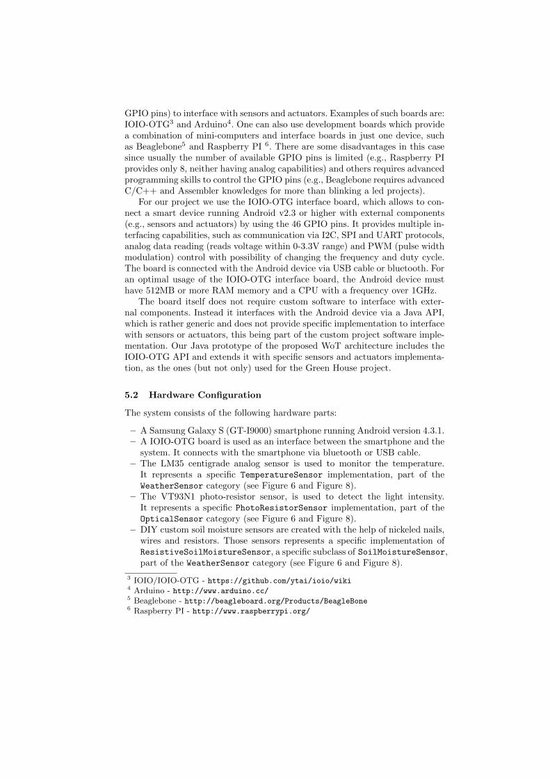
5.2 Hardware Configuration
The system consists of the following hardware parts:
– A Samsung Galaxy S (GT-I9000) smartphone running Android version 4.3.1.– A IOIO-OTG board is used as an interface between the smartphone and the
system. It connects with the smartphone via bluetooth or USB cable.– The LM35 centigrade analog sensor is used to monitor the temperature.
It represents a specific TemperatureSensor implementation, part of theWeatherSensor category (see Figure 6 and Figure 8).
– The VT93N1 photo-resistor sensor, is used to detect the light intensity.It represents a specific PhotoResistorSensor implementation, part of theOpticalSensor category (see Figure 6 and Figure 8).
– DIY custom soil moisture sensors are created with the help of nickeled nails,wires and resistors. Those sensors represents a specific implementation ofResistiveSoilMoistureSensor, a specific subclass of SoilMoistureSensor,part of the WeatherSensor category (see Figure 6 and Figure 8).
3 IOIO/IOIO-OTG - https://github.com/ytai/ioio/wiki4 Arduino - http://www.arduino.cc/5 Beaglebone - http://beagleboard.org/Products/BeagleBone6 Raspberry PI - http://www.raspberrypi.org/
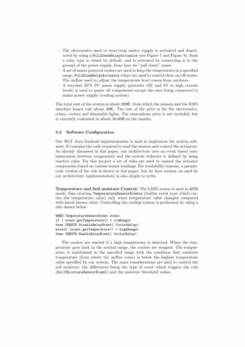
– The electrovalve used to start/stop watter supply is activated and deacti-vated by using a PullDownRelayActuator (see Figure 7 and Figure 8). Sucha relay type is closed by default, and is activated by connecting it to theground of the power supply, from here its ”pull down” name.
– A set of mains powered coolers are used to keep the temperature in a specifiedrange. PullDownRelayActuator relays are used to control their on/off states.The airflow used to adjust the temperature level comes from outdoors.
– A recycled ATX PC power supply (provides 12V and 5V at high currentlevels) is used to power all components except the ones being connected tomains power supply (cooling system).
The total cost of the system is about 200e , from which the sensors and the IOIOinterface board cost about 50e . The rest of the price is for the electrovalve,relays, coolers and dimmable lights. The smartphone price is not included, butis currently evaluated to about 50-60e on the market.
5.3 Software Configuration
Our WoT Java/Android implementation is used to implement the system soft-ware. It contains the code required to read the sensors and control the actuators.As already discussed in this paper, our architecture uses an event based com-munication between components and the system behavior is defined by usingreactive rules. For this project a set of rules are used to control the actuatorcomponents based on various sensor readings. For readability reasons, a pseudo-code version of the rule is shown in this paper, but its Java version (as used byour architecture implementation) is also simple to write.
Temperature and Soil moisture Control: The LM35 sensor is used in AUTOmode, thus creating TemperatureSensorEvents (builtin event type which car-ries the temperature value) only when temperature value changed comparedwith latest known value. Controlling the cooling system is performed by using arule shown below:
WHEN TemperatureSensorEvent event
if ( event.getTemperature() < lowRange)
then CREATE DisableRelayEvent( CoolerRelay)
elseif (event.getTemperature() > highRange)
then CREATE EnableRelayEvent( CoolerRelay)
The coolers are started if a high temperature is detected. When the tem-perature goes back in the normal range, the coolers are stopped. The temper-ature is maintained in the specified range with the condition that outdoorstemperature (from where the airflux come) is below the highest temperaturevalue specified by our system. The same considerations are used to control thesoil moisture, the differences being the type of event which triggers the rule(SoilMoistureSensorEvent) and the moisture threshold values.
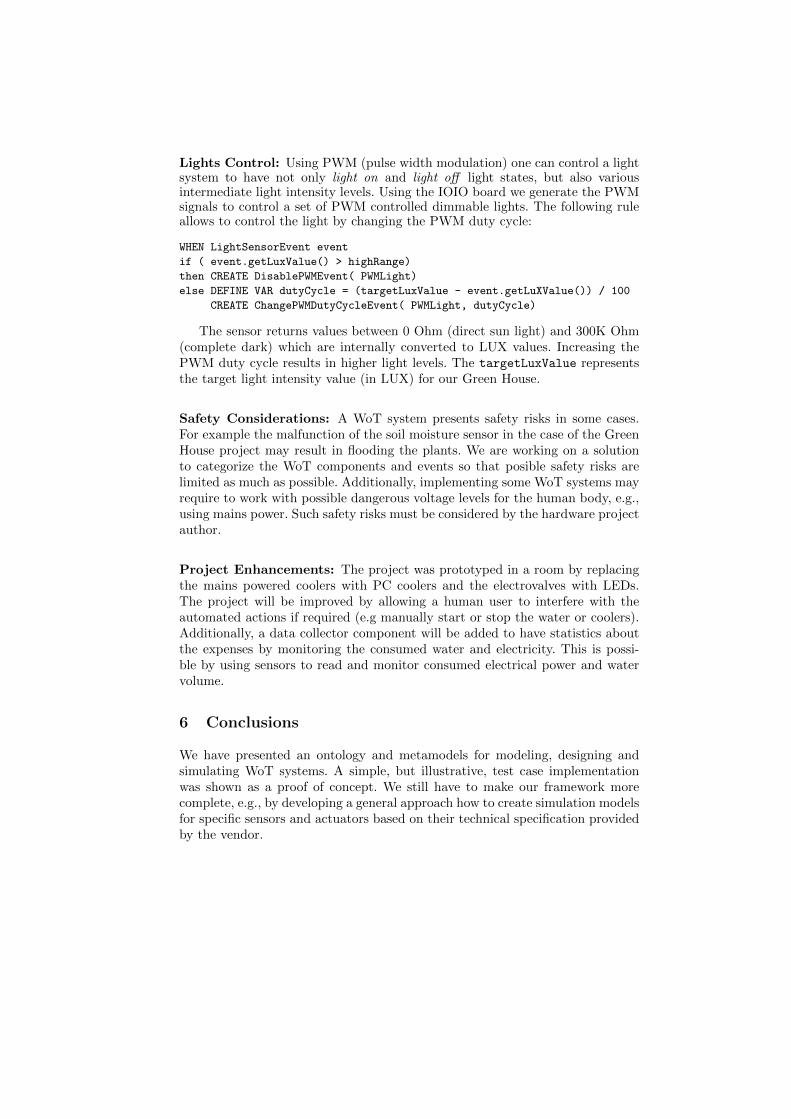
Lights Control: Using PWM (pulse width modulation) one can control a lightsystem to have not only light on and light off light states, but also variousintermediate light intensity levels. Using the IOIO board we generate the PWMsignals to control a set of PWM controlled dimmable lights. The following ruleallows to control the light by changing the PWM duty cycle:
WHEN LightSensorEvent event
if ( event.getLuxValue() > highRange)
then CREATE DisablePWMEvent( PWMLight)
else DEFINE VAR dutyCycle = (targetLuxValue - event.getLuXValue()) / 100
CREATE ChangePWMDutyCycleEvent( PWMLight, dutyCycle)
The sensor returns values between 0 Ohm (direct sun light) and 300K Ohm(complete dark) which are internally converted to LUX values. Increasing thePWM duty cycle results in higher light levels. The targetLuxValue representsthe target light intensity value (in LUX) for our Green House.
Safety Considerations: A WoT system presents safety risks in some cases.For example the malfunction of the soil moisture sensor in the case of the GreenHouse project may result in flooding the plants. We are working on a solutionto categorize the WoT components and events so that posible safety risks arelimited as much as possible. Additionally, implementing some WoT systems mayrequire to work with possible dangerous voltage levels for the human body, e.g.,using mains power. Such safety risks must be considered by the hardware projectauthor.
Project Enhancements: The project was prototyped in a room by replacingthe mains powered coolers with PC coolers and the electrovalves with LEDs.The project will be improved by allowing a human user to interfere with theautomated actions if required (e.g manually start or stop the water or coolers).Additionally, a data collector component will be added to have statistics aboutthe expenses by monitoring the consumed water and electricity. This is possi-ble by using sensors to read and monitor consumed electrical power and watervolume.
6 Conclusions
We have presented an ontology and metamodels for modeling, designing andsimulating WoT systems. A simple, but illustrative, test case implementationwas shown as a proof of concept. We still have to make our framework morecomplete, e.g., by developing a general approach how to create simulation modelsfor specific sensors and actuators based on their technical specification providedby the vendor.

References
1. Consorzio Ferrara Ricerche. Project Deliverable D1.1 - SOTA report on existingintegration frameworks/architectures for WSN, RFID and other emerging IoT re-lated Technologies, Alessandro Bassi (Eds.), 2011, http://www.iot-a.eu/public/public-documents/documents-1/1/1/d1.1/at_download/file
2. FhG IML. Deliverable D1.3 Updated reference model for IoT v1.5, An-dreas Nettstrter (Eds.), 2012, http://www.iot-a.eu/public/public-documents/documents-1/1/1/D1.3/at_download/file
3. Dominique Guinard. A Web of Things Application Architecture - Integrating theReal-World into the Web, 2011, https://www.webofthings.org/dom/thesis.pdf
4. Gerd Wagner. AOR Modelling and Simulation Towards a General Architecturefor Agent-Based Discrete Event Simulation. In P. Giorgini et al. (Eds.): Agent-Oriented Information Systems, Springer-Verlag LNAI 3030, pp. 174188, 2004.
5. Gerd Wagner. A Short Introduction to the ER/AOR Simulation Framework. http://hydrogen.informatik.tu-cottbus.de/talks/AORS-Tutorial/
6. Giancarlo Guizzardi and Gerd Wagner. A Unified Foundational Ontology and someApplications of it in Business Modeling. In Proceedings of the CAiSE’04 Work-shops, edited by J. Grundspenkis and M. Kirikova, 3:129-143. Faculty of ComputerScience and Information Technology, Riga Technical University, Riga, Latvia. June7-11, 2004.
7. Giancarlo Guizzardi. Ontological Foundations for Structural Conceptual Models.PhD Thesis, University of Twente, The Netherlands. 2005.
8. Giancarlo Guizzardi and Gerd Wagner. Using the Unified Foundational Ontol-ogy (UFO) as a Foundation for General Conceptual Modeling Languages. InRoberto Poli (Ed.), Theory and Application of Ontologies, 175-196. Springer-Verlag Berlin/Heidelberg, 2010.
9. Edson Prestes and Joel Luis Carbonera and Sandro Rama Fiorini and Vitor A. M.Jorge and Mara Abel and Raj Madhavanb, Angela Locoro and Paulo Goncalvesand Marcos E. Barreto and Maki Habibg and Abdelghani Chibani and SbastienGrard and Yacine Amirat and Craig Schlenoff. Towards a core ontology for roboticsand automation. Robotics and Autonomous Systems 61 (2013), 1193-1204.
10. Wikipedia: Actuator, http://en.wikipedia.org/wiki/Actuator.11. Wikipedia: List of sensors, http://en.wikipedia.org/wiki/List_of_sensors.12. Wikipedia: Human interface device, http://en.wikipedia.org/wiki/Human_
interface_device.