TOTAL RELIABILITY IN AVIONICS · standardized protocols in modern avionics. Therefore, Gore...
76
TOTAL RELIABILITY IN AVIONICS GORE ® Aerospace High Speed Data Cables
Transcript of TOTAL RELIABILITY IN AVIONICS · standardized protocols in modern avionics. Therefore, Gore...

TOTAL RELIABILITY IN AVIONICS
GORE® Aerospace High Speed Data Cables

Table of contentsOverview ................................................................ 1
GORE® Ethernet Cables ........................................ 4
Standard Protocols ........................................... 4
4 Pairs (Cat5e/6/6a) .......................................... 6
Quadrax (Cat5e) ............................................... 14
2 Pairs (Cat5e) .................................................. 18
GORE® Shielded Twisted Pair Cables ..................22
GORE® CAN Bus Cables ....................................... 26
GORE® Quad Cables (Specialty Versions) .......... 30
GORE® FireWire® Cables ......................................34
GORE® Fibre Channel Cables .............................. 38
GORE® USB Cables ...............................................42
GORE® HDMI Cables ............................................ 46
GORE® DVI Cables (Digital Only) ......................... 50
GORE® Fiber Optic Cables ................................... 54
1.8 mm Simplex ............................................... 54
1.2 mm Simplex ............................................... 60
900 micron ...................................................... 62
12-Fiber Ribbon ............................................... 64
GORE® Cable Protection Systems ...................... 66
GORE® Abrasion Resistant Cable Jacket ............ 68
Sample Product Inventory ................................. 72

1
Whatever type of high data rate cable your system architecture requires, Gore’s variety of high-speed data cables maintain stable communications on avionics networks.
Superior signal integrity for reliable data transmission in compact, robust designs
Engineered for demanding aircraft conditions, GORE® Aerospace High Speed Data Cables deliver superior signal integrity for reliable data transmission in small, lightweight packages. They meet and even exceed stringent industry requirements for applications such as avionics networks, cabin/flight management systems, digital video systems, in-flight entertainment and connectivity (IFEC), and more. Additionally, Gore’s high-speed copper and fiber optic solutions support the latest open-source architectures and standardized protocols such as Ethernet, USB, HDMI, Fibre Channel, and more.
Increased Durability
GORE® Aerospace High Speed Data Cables significantly reduce the challenges of installation and flight operations. The robust jacket and insulation materials in the construction resist wide temperature ranges, crushing, abrasion, and vibration. Using SAE AS4373™ method 703, Gore’s engineered fluoropolymer showed greater cut-through resistance at high temperatures compared to polytetrafluoroethylene (PTFE) and fluorinated ethylene propylene (FEP) (Figure 1).
Also, Gore’s materials are chemically inert, which reduces reaction to harmful contaminants and undesirable fluids commonly found in aircraft environments.
Significant Weight Savings
Gore’s innovative cable technology can substantially reduce weight without sacrificing durability or signal quality. Constructed with a unique proprietary material, expanded PTFE, jacket weight is reduced by as much as 37% when compared to ethylene tetrafluoroethylene (ETFE) and 50% when compared to FEP.
The excellent electrical performance of Gore’s cables can also reduce the need for additional signal amplification further decreasing weight and power requirements.
Easier Installation
Gore’s entire line of high-speed data cables facilitates easier installation for aircraft maintainers. The lighter weight jacket and insulation materials result in smaller gauge sizes in your system architecture where space is at a premium. Using SAE AS4373™ method 707, Gore’s engineered fluoropolymer also proved to be much more flexible when compared to PTFE and FEP (Figure 2).
The lighter weight materials, smaller diameters, increased flexibility, and tighter bending capability make initial routing simpler, particularly when retrofitting Gore’s cables in crowded areas.

2
Temperature (°C)
Forc
e to
Fai
lure
(lb)
250
200
150
100
50
23 700
150
Cut-Through Resistance Comparison
FEP Material
PTFE Material
Gore EngineeredFluoropolymer
Material Type
Max
imum
Ben
d To
rque
(N-c
m)
45
35
30
15
0
40
25
20
10
5
Better Performance
Bend Torque Comparison
FEP Material
PTFE Material
Gore EngineeredFluoropolymer
Figure 1: Cut-Through Resistance at High Temperatures
Figure 2: Flexure Comparison
GORE® Aerospace High Speed Data Cables

3
Benefits of GORE® Aerospace High Speed Data Cables
▪ Excellent signal integrity with stable performance in extreme conditions
▪ High-speed data transmission minimizing the need for additional signal amplification
▪ Increased durability due to materials that resist crushing, abrasion and cut-through
▪ Longer product life with chemically inert and temperature-resistant materials
▪ Fast routing due to smaller, lighter weight designs with more flexibility and tighter bend radius
GORE® Aerospace High Speed Data Cables
4
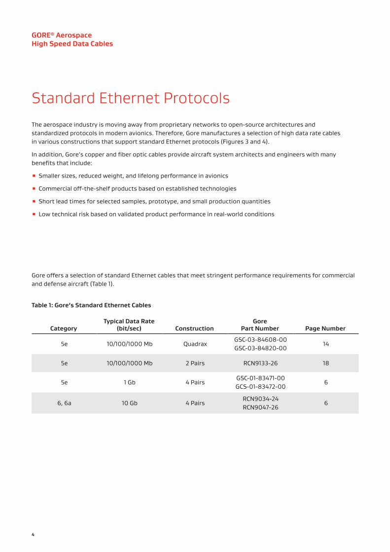
Standard Ethernet ProtocolsThe aerospace industry is moving away from proprietary networks to open-source architectures and standardized protocols in modern avionics. Therefore, Gore manufactures a selection of high data rate cables in various constructions that support standard Ethernet protocols (Figures 3 and 4).
In addition, Gore’s copper and fiber optic cables provide aircraft system architects and engineers with many benefits that include:
▪ Smaller sizes, reduced weight, and lifelong performance in avionics
▪ Commercial off-the-shelf products based on established technologies
▪ Short lead times for selected samples, prototype, and small production quantities
▪ Low technical risk based on validated product performance in real-world conditions
Gore offers a selection of standard Ethernet cables that meet stringent performance requirements for commercial and defense aircraft (Table 1).
Table 1: Gore’s Standard Ethernet Cables
CategoryTypical Data Rate
(bit/sec) ConstructionGore
Part Number Page Number
5e 10/100/1000 Mb QuadraxGSC-03-84608-00GSC-03-84820-00
14
5e 10/100/1000 Mb 2 Pairs RCN9133-26 18
5e 1 Gb 4 PairsGSC-01-83471-00GCS-01-83472-00
6
6, 6a 10 Gb 4 PairsRCN9034-24RCN9047-26
6

5
Figure 4: Cable Types Supporting Cat6a Protocol
Cat6a 1000/10000 BASE-T
Ethernet (4 Pairs) Page 6
Fiber Optics (1.8 mm Simplex)
Page 54
Figure 3: Cable Types Supporting Cat5e Protocol
Cat5e 10/100 BASE-T
Ethernet (4 Pairs) Page 6
Ethernet (Quadrax)
Page 14
Ethernet (2 Pairs)Page 18
Shielded Twisted Pair
Page 22
Fiber Optics (1.8 mm Simplex)
Page 54
Gore manufactures a selection of high data rate cables in various constructions that support standard Ethernet protocols.

GORE® Aerospace High Speed Data Cables
6
GORE® Ethernet Cables (4 Pairs, Cat5e/6/6a)For standard Ethernet protocols, Gore’s 4-pair cables are engineered for the increasing data demands of modern airborne digital networks (Table 2). The Cat6a version exceeds stringent electrical requirements and delivers excellent signal integrity with sufficient margin for high-speed data transmission up to 10 Gb at lengths up to 80 m (262 ft). This award-winning Cat6a version is also approved to SAE AS6070™ standards and on the Qualified Products List (QPL).
In addition, the unique design of these cables is 24% smaller and 25% lighter than alternative designs and proven to save 5.9 kg/km (13 lb/1000 ft) on aircraft (Figures 5 and 6). The reduced cable diameter also allows for greater flexibility and a tighter bend radius making routing easier and faster for maintainers.
Typical Applications
▪ Avionics networks ▪ Cabin/flight management systems
▪ Digital video systems ▪ Ethernet backbone ▪ Civil/defense program upgrades (C-130, F-16, KC-135, UH-60)
Standards Compliance
▪ ABD0031 (AITM 2.0005); BSS7230; FAR Part 25, Appendix F, Part I: Flammability
▪ ABD0031 (AITM 3.0005); BSS7239: Toxicity
▪ ABD0031 (AITM 3.0008B); BSS7238; FAR Part 25, Appendix F, Part V: Smoke Density
▪ ANSI/NEMA WC 27500: Environmental Testing, Jacket and Marking
▪ ANSI/TIA 568-C.2: Performance Requirements
▪ IEEE 802.3: Ethernet 10G BASE-T
▪ SAE AS4373™: Test Methods for Insulated Electric Wire (Contact Gore for available data)
▪ SAE AS6070™/5 & /6: Ethernet 1000BASE-T (10 Gb, 100 Ohms); QPL (RCN9034-24, RCN9047-26)
Table 2: Cable Properties
ElectricalProperty Value
Standard Impedance (Ohms) 100 ± 10
Typical Operating Voltage (V) < 15
Nominal Velocity of Propagation (%) 80
Nominal Time Delay ns/m (ns/ft) 4.10 (1.25)
Capacitance pF/m (pF/ft) 42.6 (13.0)
Minimum Near-End Crosstalk (NEXT) (dB) 10 MHz 100 MHz 500 MHz
59.252.342.2
Shielding Effectiveness (dB) > 55
Dielectric Withstanding Voltage (Vrms) Conductor-to-Conductor Conductor-to-Shield
15001000
Mechanical / EnvironmentalProperty Value
Jacket Material Engineered Fluoropolymer
Jacket Color White (Laser Markable)
Conductor Silver-Plated Copper/SPC Alloy
Conductor Color-Coding
Solid Blue & White/Blue Stripe,Solid Orange & White/Orange Stripe,
Solid Green & White/Green Stripe, Solid Brown & White/Brown Stripe
Dielectric Material ePTFE/PTFE
Temperature Range (°C) -65 to +200

7
Figure 5: High-Density Construction
Figure 6: Reduced Cable Diameter

8
NEX
T (d
B)
-10
-20
-30
-40
-50
-60
-70
0.0 0.1 0.2 0.3 0.4 0.5
-80
-90
-1000.6 0.7 0.8 0.9 1.0
0 Better Performance
Frequency (MHz)
IndustrySpec.
Crosstalk Comparison
AlternativeCable 1
AlternativeCable 2
GORE® EthernetCables
Frequency (MHz)
ICR
(dB)
10
0
-10
-20
-30
-40
-50
-60
-70
-80
-900 100 200 300 400 500
Attenuation Comparison
AlternativeCable 1
AlternativeCable 2
GORE® EthernetCables
Better Performance
Figure 8: Crosstalk Comparison
Improved Electrical PerformanceGore compared its Cat6a cable with several leading alternative cables. The improved performance of GORE® Ethernet Cables (4 Pairs) translates directly to more reliable data transmission with vastly better insertion loss to crosstalk ratio (Figure 7). The excellent performance of these cables provide additional margin to overcome installation issues and operational challenges. Similarly, results also indicated that Gore’s unique cable design can reduce crosstalk right out of the box by more than 10 dB at 500 MHz compared to alternative cables (Figure 8).
GORE® Ethernet Cables (4 Pairs, Cat5e/6/6a)
Figure 7: Insertion Loss to Crosstalk Ratio Comparison

9
Inse
rtio
n Lo
ss (d
B)
0
-10
-20
-30
-40
-50
-60
-70
.1 1 10-90
100 1000
-80
0
Better Performance
Shielding Effectiveness
Frequency (MHz)
AlternativeCable 1
AlternativeCable 2
GORE® EthernetCables
Figure 9: Shielding Effectiveness Comparison
Results also showed that Gore’s Cat6a cable improves signal integrity and reduces RF interference by as much as 20 dB at higher frequencies among multiple electronic systems (Figure 9). Proof that Gore’s innovative cable design provides better noise immunity and less EMI emissions compared to alternative cables.
Figure 10: Peel-Back MethodCable Preparation Laser stripping is the ideal method to prep GORE® Ethernet Cables (4 Pairs). Alternatively, Gore recommends using thermal or sharp mechanical strippers. Also, a unique method is to make a short, horizontal slit in the jacket material, peel it back to allow for contact termination and return the jacket to its original position for a neat closure (Figure 10).

10
Table 3: Ethernet Cat6a Interconnect Options
Gore’s RCN8966-26 version includes a unique inverted dielectric for termination with a variety of high-speed aerospace connector systems such as Amphenol® Octonet and HARTING RJ Industrial®. Please contact a Gore representative for additional connector systems not listed in the table.
Gore Part Number
Connector System RCN8966-24 RCN9034-24 RCN8966-26 RCN9047-26 RCN9034-28
Amphenol® Octonet
Amphenol® Oval Contact System (OCS13-53)
Amphenol® µ-Com
Bel Stewart SS-39200 Series
Carlisle Octax® M38999 (Size 11)
Glenair El Ochito®
HARTING RJ Industrial® 10G RJ45 (Part Number 09451511560)
ITT Cannon OctoGig™
LEMO® 2B Series
Omnetics Micro 360® Cat6a
Platinum® Tools EZ-RJ45® 106193
Sentinel® 111S08080095HA4
Sentinel® 111S08080095LA4
TE Connectivity® CeeLok FAS-T®
TE Connectivity® CeeLok FAS-X®
GORE® Ethernet Cables (4 Pairs, Cat5e/6/6a)
Connector-Cable CompatibilityGore also evaluated the electrical characteristics of its Cat6a cable terminated with leading high-speed aerospace connector systems to assist designers in selecting the best option for a specific application (Table 3). Testing connector-cable compatibility during the initial design process ensures interconnects will perform reliably in specific applications.
Visit gore.com/ethernet-cable-connectors to download Gore’s best practices for terminating GORE® Ethernet Cables (4 Pairs) with leading high-speed aerospace connectors and related electrical data.

11
Figure 11: Cable Routing SimulatorProven Installed PerformanceGore designed a simulator to evaluate the effects of severe bending on high-speed data cables while being routed through an airframe (Figure 11). The simulator has various mandrels located in fixed positions for repeatability that replicate minimum bend radius conditions. The simulator also includes two cable cleats to hold tension.
Testing characteristics such as return loss and crosstalk after routing through the simulator verifies whether a cable can withstand the complex challenges of installation that can degrade signal integrity. Gore routed a 2-m (6.5-ft) cable through the simulator for 4 cycles and measured the electrical performance of its Cat6a cable and alternative cables.
Results showed that Gore’s Cat6a cable maintained sufficient margin below the specification limit for return loss compared to the alternative cables (Figure 12). Gore’s cable provided consistent impedance control at higher frequencies after routing, indicating reliable high data rate transfer at 10 Gb. Similarly, Gore’s Cat6a cable maintained a consistent margin of 20 dB providing lower crosstalk after routing, while the alternative cables showed a slight change in the margin (Figure 13).
Gore’s testing proved that GORE® Ethernet Cables (4 Pairs) deliver exceptional performance after installation, reduce maintenance and downtime, and lower total costs over time.
For more information regarding selecting, designing and installing the right Ethernet interconnect to ensure reliable performance in aircraft, visit gore.com/highdatarateaircraftcables.

12
Figure 13: Crosstalk Comparison after Routing
GORE® Ethernet Cables (4 Pairs, Cat5e/6/6a)
Ret
urn
Loss
(dB)
0
-5
-10
-15
-20
-25
0 50 100 150 200 250
-35
300 350 400 450 500
-30
-45
-40
Better Performance
Return Loss After Routing
Frequency (MHz)
IndustrySpec.
AlternativeCable 1
AlternativeCable 2
GORE® EthernetCables
NEX
T (d
B)
0
-10
-20
-30
-40
-50
-60
-70
-90
-80
0 50 100 150 200 250 300 350 400 450 500
Better Performance
Near-End Crosstalk After Routing
Frequency (MHz)
IndustrySpec.
AlternativeCable 1
AlternativeCable 2
GORE® EthernetCables
Figure 12: Return Loss Comparison after Routing

13
Table 4: Cable Characteristics
Insertion loss values are based on the maximum recommended use length. Also, Gore’s Cat6a version RCN9034-24 and RCN9047-26 are approved to SAE AS6070™ standards that support AS50881 EWIS (electrical wiring interconnection systems) specifications and on the Qualified Products List (QPL).
Ordering InformationGORE® Ethernet Cables (4 Pairs) are available in standard sizes (Table 4). Visit gore.com/cable-distributors for the list of distributors. In addition, see page 72 regarding Gore’s full inventory of sample products and lead times.
For more information or to discuss specific characteristic limits and application needs, please contact a Gore representative.
Cat6a
Gore Part Number
AWG Size (Stranding)
Maximum Outer
Diameter mm (in)
Minimum Bend Radius
mm (in)
Nominal Weight kg/km
(lb/1000 ft)
Typical Insertion LossdB/30 m (100 ft)
100 MHz
200 MHz
500 MHz
RCN8966-24 24 (19/36) 6.9 (0.27) 13.7 (0.54) 67.0 (45.0) 5.6 8.1 14.1
RCN9034-24 24 (19/36) 6.6 (0.26) 13.2 (0.52) 62.5 (42.0) 5.6 8.1 14.1
RCN8966-26 26 (19/38) 5.8 (0.23) 11.6 (0.46) 52.1 (35.0) 6.9 9.9 17.0
RCN9047-26 26 (19/38) 5.6 (0.22) 10.2 (0.44) 47.6 (32.0) 6.9 9.9 17.0
RCN9034-28 28 (19/40) 4.6 (0.18) 8.9 (0.35) 37.2 (25.0) 8.8 12.6 21.5
Cat5e
Gore Part Number
AWG Size (Stranding)
Maximum Outer
Diameter mm (in)
Minimum Bend Radius
mm (in)
Nominal Weight kg/km
(lb/1000 ft)
Maximum Insertion LossdB/30 m (100 ft)
10 MHz
100 MHz
GSC-01-83471-00 24 (19/36) 6.3 (0.25) 30.0 (1.18) 56.0 (37.0) 6.5 22.0
GSC-01-83472-00 26 (19/38) 4.9 (0.19) 20.0 (0.79) 49.0 (32.9) 6.5 22.0

GORE® Aerospace High Speed Data Cables
14
GORE® Ethernet Cables (Quadrax, Cat5e)Gore offers a star quadrax cable that is a reliable substitute for dual twisted pairs to meet Ethernet Cat5e requirements in advanced avionics (Table 5). These dual differential pairs transmit continuous bi-directional, high-speed signals up to 100 MHz at lengths up to 70 m (230 ft) using size 24 AWG and 50 m (164 ft) using size 26 AWG.
Gore is the original inventor of this pioneering cable geometry that is approximately 40% smaller than dual twisted pair constructions. The cable’s lightweight build is also proven to save more than 5.0 kg (11 lb) on aircraft such as the fifth-generation F-35 (Figure 14).
Typical Applications
▪ Avionics networks ▪ Box-to-box systems ▪ Digital visual interface (DVI) ▪ Ethernet backbone ▪ Flight control ▪ Mission systems ▪ Propulsion control
Standards Compliance
▪ ABD0031 (AITM 2.0005); BSS7230; FAR Part 25, Appendix F, Part I: Flammability
▪ ABD0031 (AITM 3.0005); BSS7239: Toxicity
▪ ABD0031 (AITM 3.0008B); BSS7238; FAR Part 25, Appendix F, Part V: Smoke Density
▪ AFDX/ARINC 664, Part 7: Ethernet Networks
▪ ANSI/NEMA WC 27500: Environmental Testing, Jacket and Marking
▪ IEEE 802.3: Ethernet 100BASE-T / 1000BASE-T (2 cables)
▪ SAE AS4373™: Test Methods for Insulated Electric Wire (Contact Gore for available data)
Table 5: Cable Properties
ElectricalProperty Value
Standard Impedance (Ohms) 100 ± 10
Typical Operating Voltage (V) < 15
Nominal Velocity of Propagation (%) 80
Nominal Time Delay ns/m (ns/ft) 4.10 (1.25)
Capacitance pF/m (pF/ft) 50.0 (15.2)
Minimum Near-End Crosstalk (NEXT) (dB) 10 MHz 100 MHz
50.035.0
Dielectric Withstanding Voltage (Vrms) Conductor-to-Conductor Conductor-to-Shield
2500
Mechanical / EnvironmentalProperty Value
Jacket Material Engineered Fluoropolymer
Jacket Color White (Laser Markable)
Conductor Silver-Plated Copper Alloy
Conductor Color-Coding Blue/Red, Green/Yellow
Dielectric Material ePTFE/PTFE
Temperature Range (°C) -65 to +200

15
Figure 14: Lightweight Build
Figure 15: Peel-Back Method
Cable PreparationLaser stripping is the ideal method to prep GORE® Ethernet Cables (Quadrax). Alternatively, Gore recommends using thermal or sharp mechanical strippers. Also, a unique method is to make a short, horizontal slit in the jacket material, peel it back to allow for contact termination and return the jacket to its original position for a neat closure (Figure 15). For more information regarding cable preparation, please contact a Gore representative.
Contact-Connector OptionsGORE® Ethernet Cables (Quadrax) are designed to fit a variety of high-speed aerospace connector systems and backshells such as ARINC and MIL-STD-38999 with size 8 contacts. Please contact the specific manufacturer such as Amphenol® and Glenair for exact part numbers, tooling information, and termination instructions.

16
Ordering InformationGORE® Ethernet Cables (Quadrax) are available in standard sizes (Table 6). Visit gore.com/cable-distributors for the list of distributors. In addition, see page 72 regarding Gore’s full inventory of sample products and lead times.
For more information or to discuss specific characteristic limits and application needs, please contact a Gore representative. Also, see page 30 regarding Gore’s specialty quadrax version with tighter skew requirements for high-speed serial data protocols.
Table 6: Cable Characteristics
Typical insertion loss values are based on the maximum recommended Cat5e use lengths.
Gore Part Number
AWG Size (Stranding)
Nominal Outer
Diameter mm (in)
Minimum Bend Radius
mm (in)
Nominal Weight kg/km
(lb/1000 ft)
Maximum Insertion LossdB/30 m (100 ft)
10 MHz
100 MHz
GSC-03-84608-00 24 (19/36) 4.1 (0.16) 20.0 (0.79) 33.0 (22.0) 2.8 9.4
GSC-03-84820-00 26 (19/38) 3.3 (0.13) 15.0 (0.59) 23.0 (15.0) 3.9 13.2
GORE® Ethernet Cables (Quadrax, Cat5e)

17
Gore’s Ethernet cables are proven to save more than 5.0 kg (11 lb) on aircraft such as the fifth-generation F-35.

GORE® Aerospace High Speed Data Cables
18
GORE® Ethernet Cables (2 Pairs, Cat5e)For Ethernet Cat5e protocol, Gore’s 2-pair cable preserves signal integrity, significantly exceeds crosstalk requirements, and reliably carries high-speed data up to 1 GHz (Table 7). Also, positioning two of these cables side by side can achieve Ethernet 1000BASE-T performance in avionics.
Gore’s mechanically strong cable can easily tolerate difficult conditions such as extreme temperatures and constant vibration during flight. It also has a smaller form factor that is highly flexible with tighter bending capability, which means simpler routing and quicker installation in complex airframes with less space (Figure 16).
Typical Applications
▪ Avionics networks ▪ Cabin management systems ▪ Digital video systems ▪ Ethernet backbone ▪ Serial buses
Standards Compliance
▪ ABD0031 (AITM 2.0005); BSS7230; FAR Part 25, Appendix F, Part I: Flammability
▪ ABD0031 (AITM 3.0005); BSS7239: Toxicity
▪ ABD0031 (AITM 3.0008B); BSS7238; FAR Part 25, Appendix F, Part V: Smoke Density
▪ ANSI/NEMA WC 27500: Environmental Testing, Jacket and Marking
▪ ANSI/TIA 568-C.2: Performance Requirements
▪ IEEE 802.3: Ethernet 100BASE-T / 1000BASE-T (2 cables)
▪ SAE AS4373™: Test Methods for Insulated Electric Wire (Contact Gore for available data)
Table 7: Cable Properties
ElectricalProperty Value
Standard Impedance (Ohms) 100 + 10/-5
Typical Operating Voltage (V) < 15
Nominal Velocity of Propagation (%) 80
Nominal Time Delay ns/m (ns/ft) 4.10 (1.25)
Capacitance pF/m (pF/ft) 41.0 (12.5)
Minimum Near-End Crosstalk (NEXT) (dB) 10 MHz 100 MHz
59.252.3
Dielectric Withstanding Voltage (Vrms) Conductor-to-Conductor Conductor-to-Shield
15001000
Mechanical / EnvironmentalProperty Value
Jacket Material Engineered Fluoropolymer
Jacket Color White (Laser Markable)
Conductor Silver-Plated Copper/SPC Alloy
Conductor Color-CodingSolid Green & White/Green Stripe,
Solid Orange & White/Orange Stripe
Dielectric Material ePTFE/PTFE
Temperature Range (°C) -65 to +200

19
Figure 16: Smaller Form Factor
Cable PreparationLaser stripping is the ideal method to prep GORE® Ethernet Cables (2 Pairs). Alternatively, Gore recommends using thermal or sharp mechanical strippers. Also, a unique method is to make a short, horizontal slit in the jacket material, peel it back to allow for contact termination and return the jacket to its original position for a neat closure (Figure 17). For more information regarding cable preparation, please contact a Gore representative.
Contact-Connector OptionsGORE® Ethernet Cables (2 Pairs) are designed to fit a variety of high-speed aerospace connector systems and backshells such as ARINC and MIL-STD-38999 with size 8 contacts. Please contact the specific manufacturer such as Amphenol® and Glenair for exact part numbers, tooling information, and termination instructions.
Figure 17: Peel-Back Method
20
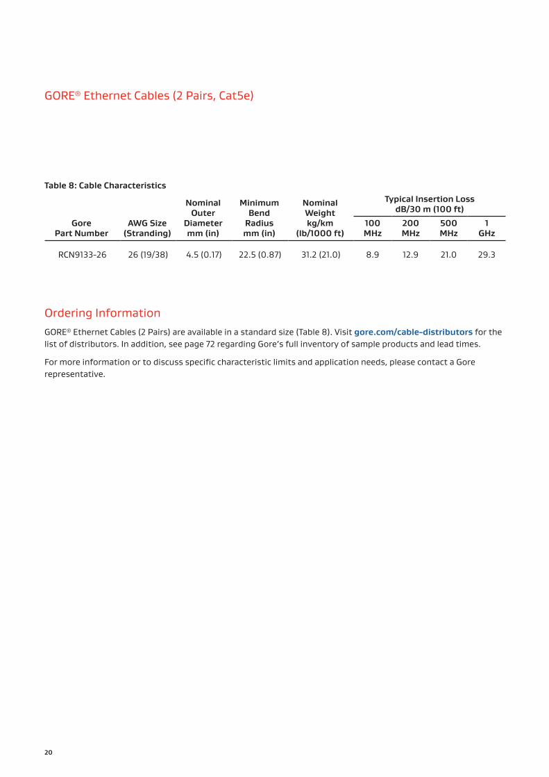
Table 8: Cable Characteristics
Gore Part Number
AWG Size (Stranding)
Nominal Outer
Diameter mm (in)
Minimum Bend
Radius mm (in)
Nominal Weight kg/km
(lb/1000 ft)
Typical Insertion LossdB/30 m (100 ft)
100 MHz
200 MHz
500 MHz
1 GHz
RCN9133-26 26 (19/38) 4.5 (0.17) 22.5 (0.87) 31.2 (21.0) 8.9 12.9 21.0 29.3
Ordering InformationGORE® Ethernet Cables (2 Pairs) are available in a standard size (Table 8). Visit gore.com/cable-distributors for the list of distributors. In addition, see page 72 regarding Gore’s full inventory of sample products and lead times.
For more information or to discuss specific characteristic limits and application needs, please contact a Gore representative.
GORE® Ethernet Cables (2 Pairs, Cat5e)

21
Passengers can use their devices while traveling with Gore’s 2-pair Ethernet cable transferring data and video continuously at high speeds.

GORE® Aerospace High Speed Data Cables
22
GORE® Shielded Twisted Pair Cables (Controlled Impedance, 100 Ohms)
Well-suited for aerospace harness applications, Gore’s cables utilize low-voltage differential signals (LVDS). They deliver excellent signal integrity with controlled impedance for data transmission lines at speeds up to 1 GHz (Table 9).
The combination of durable materials in this construction enables a higher tolerance against typical aircraft conditions such as rapidly-changing environments at high altitudes for extended service life (Figure 18).
Gore’s low-profile configuration also has a direct impact on saving weight in aircraft. These cables are 30% smaller and 50% lighter when compared to standard oval cables (Figure 19). When compared to alternative round cables, Gore’s unique design is drastically smaller in size (Figure 20). This smaller diameter allows for more flexibility and easier routing in hard-to-reach places of an airframe for improved installation.
Typical Applications
▪ Avionics networks ▪ Cabin management systems ▪ Digital video systems ▪ Ethernet backbone ▪ LVDS devices ▪ Serial buses
Standards Compliance
▪ ABD0031 (AITM 2.0005); BSS7230; FAR Part 25, Appendix F, Part I: Flammability
▪ ABD0031 (AITM 3.0005); BSS7239: Toxicity
▪ ABD0031 (AITM 3.0008B); BSS7238; FAR Part 25, Appendix F, Part V: Smoke Density
▪ ANSI/NEMA WC 27500: Environmental Testing, Jacket and Marking
▪ RoHS and REACH Information (See Table 10)
▪ SAE AS4373™: Test Methods for Insulated Electric Wire (Contact Gore for available data)
Table 9: Cable PropertiesPlease contact a Gore representative for other impedance options.
ElectricalProperty Value
Standard Impedance (Ohms) 100 ± 10
Typical Operating Voltage (V) < 15
Nominal Velocity of Propagation (%) 80
Nominal Time Delay ns/m (ns/ft) 4.10 (1.25)
Capacitance pF/m (pF/ft) 42.6 (13.0)
Dielectric Withstanding Voltage (Vrms) Conductor-to-Conductor Conductor-to-Shield
15001000
Mechanical / EnvironmentalProperty Value
Jacket Material Engineered Fluoropolymer
Jacket Color White (Laser Markable)
Conductor Silver-Plated Copper Alloy
Conductor Color-Coding Blue/White
Dielectric Material ePTFE/PTFE
Temperature Range (°C) -65 to +200

23
Figure 18: Durable Package
Figure 19: Low-Profile Configuration Figure 20: Smaller Diameter

24
Table 10: Cable Characteristics
Gore alternative part numbers for GORE® Shielded Twisted Pair Cables meet the substance requirements according to the RoHS Directive 2011/65/EU that also includes Commission Delegated Directive 2015/863. These products do not contain any substances on the Candidate List of Substances of Very High Concern (SVHC) at concentrations above 0.1% (w/w) currently published on the ECHA website as of January 15, 2019.
Gore Part
Number
Gore Alternative
Part NumberAWG Size
(Stranding)
Nominal Outer
Diameter mm (in)
Minimum Bend
Radius mm (in)
Nominal Weight kg/km
(lb/1000 ft)
Maximum Insertion LossdB/30 m (100 ft)
100 MHz
200 MHz
500 MHz
1 GHz
DXN2600GSC-03-
84879-0020 (19/32) 5.1 (0.20) 25.0 (0.98) 31.7 (21.3) 4.8 6.8 11.3 16.4
DXN2601GSC-03-
84880-0022 (19/34) 3.8 (0.15) 19.1 (0.75) 23.2 (15.6) 6.6 9.8 15.7 23.5
DXN2602GSC-03-
84557-0024 (19/36) 3.3 (0.13) 16.2 (0.64) 16.8 (11.3) 7.6 10.7 17.3 25.0
DXN2603GSC-03-
84823-0026 (19/38) 2.5 (0.10) 12.6 (0.49) 12.8 (8.6) 9.4 13.8 21.5 31.2
DXN2604GSC-03-
84881-0028 (19/40) 2.0 (0.08) 9.9 (0.39) 8.6 (5.8) 13.2 19.2 32.0 46.8
DXN2605GSC-03-
84710-0030 (19/42) 1.8 (0.07) 8.9 (0.35) 7.1 (4.8) 20.9 23.6 38.3 56.9
DXN2606 — 32 (19/44) 1.7 (0.07) 8.6 (0.34) 5.0 (3.4) 27.0 39.0 60.0 —
GORE® Shielded Twisted Pair Cables (Controlled Impedance, 100 Ohms)

25
Cable PreparationLaser stripping is the ideal method to prep GORE® Shielded Twisted Pair Cables. Alternatively, Gore recommends using thermal or sharp mechanical strippers. Also, a unique method is to make a short, horizontal slit in the jacket material, peel it back to allow for contact termination and return the jacket to its original position for a neat closure (Figure 21). For more information regarding cable preparation, please contact a Gore representative.
Contact-Connector OptionsGORE® Shielded Twisted Pair Cables are designed to fit a variety of high-speed aerospace connector systems and backshells such as ARINC and MIL-STD-38999 with differential Twinax sizes 8 and 22D contacts. Please contact the specific manufacturer such as Amphenol® and Glenair for exact part numbers, tooling information, and termination instructions.
Ordering InformationGORE® Shielded Twisted Pair Cables are available in standard sizes (Table 10). Visit gore.com/cable-distributors for the list of distributors. In addition, see page 72 regarding Gore’s full inventory of sample products and lead times.
For more information or to discuss specific characteristic limits and application needs, please contact a Gore representative.
Figure 21: Peel-Back Method

GORE® Aerospace High Speed Data Cables
26
GORE® CAN Bus Cables (Controlled Impedance, 120 Ohms)
Suitable for today’s faster digital networks, Gore’s controlled-impedance cables ensure high-quality signals for high data rate transmission up to 1 GHz. They provide versatile protection to shield them from extreme mechanical and environmental impact (Table 11). These cables are built to perform accurately, reliably and securely over the aircraft’s lifespan.
With a compact footprint, Gore’s CAN Bus cables are 40% smaller than alternative cable designs, which makes them fundamentally lighter. This reduced diameter enables better flexibility and a smaller bend radius for trouble-free installation in tight aircraft areas (Figure 22).
Typical Applications
▪ Avionics networks ▪ Cabin management systems ▪ Controller area network ▪ Digital video systems ▪ Serial buses
Standards Compliance
▪ ABD0031 (AITM 2.0005); BSS7230; FAR Part 25, Appendix F, Part I: Flammability
▪ ABD0031 (AITM 3.0005); BSS7239: Toxicity
▪ ABD0031 (AITM 3.0008B); BSS7238; FAR Part 25, Appendix F, Part V: Smoke Density
▪ ANSI/NEMA WC 27500: Environmental Testing, Jacket and Marking
▪ SAE AS4373™: Test Methods for Insulated Electric Wire (Contact Gore for available data)
Table 11: Cable Properties
ElectricalProperty Value
Standard Impedance (Ohms) 120 ± 10
Typical Operating Voltage (V) < 15
Nominal Velocity of Propagation (%) 80
Nominal Time Delay ns/m (ns/ft) 4.10 (1.25)
Capacitance pF/m (pF/ft) 42.0 (12.8)
Dielectric Withstanding Voltage (Vrms) Conductor-to-Conductor Conductor-to-Shield
15001000
Mechanical / EnvironmentalProperty Value
Jacket Material Engineered Fluoropolymer
Jacket Color White (Laser Markable)
Conductor Silver-Plated Copper
Conductor Color-Coding Blue/White
Dielectric Material ePTFE/PTFE
Temperature Range (°C) -65 to +200

27
Figure 22: Compact Footprint
Cable PreparationGORE® CAN Bus Cables include an inverted dielectric design that enables easier wire preparation and insertion in smaller connector systems.
Standard 150-ohm primary wires have a much larger diameter due to high impedance and typically will not fit into smaller holes unless wires are insulated with thin heat shrink. However, Gore’s unique design eliminates the need to remove several inches of insulation from the end and apply heat shrink to fit wires into smaller holes.
The inverted dielectric layers can be stripped off using sharp mechanical strippers set at the next largest AWG size. Carefully cut the outer layers and use your fingertips to pull off gently. For more information regarding cable preparation, please contact a Gore representative.
Contact-Connector OptionsGORE® CAN Bus Cables are designed to fit a variety of high-speed aerospace connector systems and backshells such as ARINC and MIL-STD-38999 with size 8 and 22D contacts. Please contact the specific manufacturer such as Amphenol® and Glenair for exact part numbers, tooling information, and termination instructions.

28
Ordering InformationGORE® CAN Bus Cables are available in standard sizes (Table 12). Visit gore.com/cable-distributors for the list of distributors. In addition, see page 72 regarding Gore’s full inventory of sample products and lead times.
For more information or to discuss specific characteristic limits and application needs, please contact a Gore representative.
Table 12: Cable Characteristics
Gore Part Number
AWG Size (Stranding)
Nominal Outer
Diameter mm (in)
Minimum Bend Radius
mm (in)
Nominal Weight kg/km
(lb/1000 ft)
Typical Insertion LossdB/30 m (100 ft)
100 MHz
200 MHz
500 MHz
1 GHz
GSC-03-85752-22D 22 (19/34) 5.1 (0.20) 25.5 (1.00) 28.0 (18.82) 5.6 8.5 13.5 19.0
GSC-03-85752-24D 24 (19/36) 4.2 (0.17) 21.0 (0.83) 23.0 (15.46) 6.5 10.0 16.0 22.0
GSC-03-85752-26D 26 (19/38) 3.5 (0.14) 17.5 (0.69) 15.4 (10.35) 8.0 12.0 18.0 24.0
GORE® CAN Bus Cables (Controlled Impedance, 120 Ohms)

29
With a compact footprint, Gore’s CAN Bus Cables enable better flexibility and a smaller bend radius for trouble-free installation in tight aircraft areas.

GORE® Aerospace High Speed Data Cables
30
GORE® Quad Cables (Specialty Versions, Controlled Impedance, 100 Ohms)
Gore offers specialty quadrax cables with tighter skew requirements that are perfectly aligned with today’s high-speed serial data and video protocols in modern avionics (Table 13). These dual differential pairs routinely transfer bi-directional signals for data and video at speeds up to 1 GHz at lengths up to 30 m (100 ft).
These cables are constructed with remarkably strong materials and perform without failure in the most difficult aircraft conditions such as rigorous routing and extreme temperatures (Figure 23).
As the original architect of this innovative quadrax design, Gore’s cables are significantly smaller — by approximately 40% — when compared to dual twisted pair constructions (Figure 24). These cables are also proven to save more than 5.0 kg (11 lb) per aircraft.
Table 13: Cable Properties
Electrical Value
PropertyRCN8752(24 AWG)
RCN8982(26 AWG)
RCN8973(28 AWG)
Standard Impedance (Ohms) 100 ± 5 100 ± 10 100 ± 10
Typical Operating Voltage (V) < 15 < 15 < 15
Nominal Velocity of Propagation (%) > 80 > 80 > 80
Nominal Time Delay ns/m (ns/ft) 4.10 (1.25) 4.23 (1.29) 4.10 (1.25)
Capacitance pF/m (pF/ft) 50.0 (15.2) 39.4 (12.0) 42.7 (13.0)
Minimum Near-End Crosstalk (NEXT) (dB) 10 MHz 100 MHz
50.0 35.0
— —
Maximum Skew Within Pair ps/m (ps/ft) 13.12 (4.0) 13.12 (4.0) 13.12 (4.0)
Dielectric Withstanding Voltage (Vrms) Conductor-to-Conductor Conductor-to-Shield
1500 1500 1500
Mechanical / EnvironmentalProperty Value
Jacket Material Engineered Fluoropolymer
Jacket Color White (Laser Markable)
Conductor Silver-Plated Copper Alloy
Conductor Color-Coding Blue/Red, Green/Yellow
Blue/Orange,Green/Red
Black/Blue,Green/White
Dielectric Material ePTFE/PTFE ePTFE/PTFE ePTFE/PTFE
Temperature Range (°C) -65 to +200 -55 to +200 -55 to +200

31
Typical Applications
▪ Avionics networks ▪ Box-to-box systems ▪ Digital visual interface (DVI) ▪ EO/IR (electro-optical infrared) sensors ▪ Ethernet backbone ▪ Flight control ▪ Mission systems ▪ Propulsion control ▪ Video networks
Standards Compliance
▪ ABD0031 (AITM 2.0005); BSS7230; FAR Part 25, Appendix F, Part I: Flammability
▪ ABD0031 (AITM 3.0005); BSS7239: Toxicity
▪ ABD0031 (AITM 3.0008B); BSS7238; FAR Part 25, Appendix F, Part V: Smoke Density
▪ AFDX/ARINC 664, Part 7: Ethernet Networks
▪ ANSI/NEMA WC 27500: Environmental Testing, Jacket and Marking
▪ IEEE 802.3: Ethernet 1000BASE-T
▪ SAE AS4373™: Test Methods for Insulated Electric Wire (Contact Gore for available data)
Figure 23: Remarkably Strong Materials
Figure 24: Reduced Cable Design

32
Table 14: Cable Characteristics
Gore Part Number
AWG Size (Stranding)
Nominal Outer
Diameter mm (in)
Minimum Bend
Radius mm (in)
Typical Weight kg/km
(lb/1000 ft)
Typical Insertion LossdB/30 m (100 ft)
100 MHz
800 MHz
1 GHz
RCN8752 24 (19/36) 3.8 (0.15) 19.0 (0.75) 32.4 (21.7) 6.3 19.4 22.7
RCN8982 26 (19/38) 3.4 (0.14) 17.0 (0.67) 23.6 (15.8) 8.3 26.6 30.0
RCN8973 28 (19/40) 2.8 (0.11) 14.0 (0.55) 20.6 (13.8) 8.9 26.6 39.8
GORE® Quad Cables (Specialty Versions, Controlled Impedance, 100 Ohms)
Cable PreparationLaser stripping is the ideal method to prep GORE® Quad Cables. Alternatively, Gore recommends using thermal or sharp mechanical strippers. Also, a unique method is to make a short, horizontal slit in the jacket material, peel it back to allow for contact termination and return the jacket to its original position for a neat closure (Figure 25). For more information regarding cable preparation, please contact a Gore representative.
Contact-Connector OptionsGORE® Quad Cables are designed to fit a variety of high-speed aerospace connector systems and backshells such as ARINC and MIL-STD-38999 with size 8 contacts. Please contact the specific manufacturer such as Amphenol® and Glenair for exact part numbers, tooling information, and termination instructions.
Ordering InformationGORE® Quad Cables are available in standard sizes (Table 14). Visit gore.com/cable-distributors for the list of distributors. In addition, see page 72 regarding Gore’s full inventory of sample products and lead times.
For more information or to discuss specific characteristic limits and application needs, please contact a Gore representative. Also, see page 14 regarding Gore’s star quadrax version for Ethernet Cat5e protocol.
Figure 25: Peel-Back Method

33
The specialty versions of Gore’s quadrax cables are perfect for applications such as unmanned aircraft systems that use high-speed serial data and video protocols.

GORE® Aerospace High Speed Data Cables
34
GORE® FireWire® Cables (Quadrax, 110 Ohms)
Typical Applications
▪ Avionics networks ▪ Flight control ▪ Networked video systems ▪ Mission systems
Standards Compliance
▪ ABD0031 (AITM 2.0005); BSS7230; FAR Part 25, Appendix F, Part : Flammability
▪ ABD0031 (AITM 3.0005); BSS7239: Toxicity
▪ ABD0031 (AITM 3.0008B); BSS7238; FAR Part 25, Appendix F, Part V: Smoke Density
▪ ANSI/NEMA WC 27500: Environmental Testing, Jacket and Marking
▪ IEEE 1394b; SAE AS5643™: Designed to comply with performance requirements
▪ SAE AS4373™: Test Methods for Insulated Electric Wire (Contact Gore for available data)
▪ SAE AS6070™/8: High-speed data protocol cable requirements
This version of Gore’s quadrax cables is the premier solution for copper-based IEEE 1394b FireWire® data links. They transmit uninterrupted high-fidelity signals with flexure for interconnect solutions up to 30 m (100 ft) at S400 data transfer rates (Table 15).
Built with durable materials that are highly flexible, Gore’s cables provide a protective barrier against tough environments for long-term product life (Figure 26).
Also, Gore’s quadrax design is approximately 40% smaller than dual twisted pair constructions (Figure 27). These cables are also proven to save as much as 5.2 kg (11.5 lb) per aircraft.
Table 15: Cable Properties
ElectricalProperty Value
Standard Impedance (Ohms) 110 +6/-4
Typical Operating Voltage (V) < 15
Nominal Velocity of Propagation (%) 80
Nominal Time Delay ns/m (ns/ft) 4.10 (1.25)
Capacitance pF/m (pF/ft) (26 AWG) 36.1 (11.0)
Typical Skew Within Pair ps/m (ps/ft) 3.5 (1.1)
Dielectric Withstanding Voltage (Vrms) Conductor-to-Conductor Conductor-to-Shield
15001000
Mechanical / EnvironmentalProperty Value
Jacket Material Engineered Fluoropolymer
Jacket Color White (Laser Markable)
Conductor Silver-Plated Copper/SPC Alloy
Conductor Color-Coding Blue/Orange, Green/Red
Dielectric Material ePTFE/PTFE
Temperature Range (°C) -65 to +200

35
Figure 26: Highly Flexible Cable Technology
Figure 27: Smaller-Scale Dimensions
36
GORE® FireWire® Cables (Quadrax, 110 Ohms)
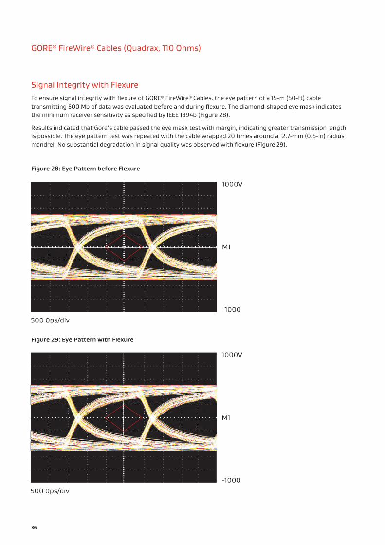
Signal Integrity with FlexureTo ensure signal integrity with flexure of GORE® FireWire® Cables, the eye pattern of a 15-m (50-ft) cable transmitting 500 Mb of data was evaluated before and during flexure. The diamond-shaped eye mask indicates the minimum receiver sensitivity as specified by IEEE 1394b (Figure 28).
Results indicated that Gore’s cable passed the eye mask test with margin, indicating greater transmission length is possible. The eye pattern test was repeated with the cable wrapped 20 times around a 12.7-mm (0.5-in) radius mandrel. No substantial degradation in signal quality was observed with flexure (Figure 29).
500 0ps/div
1000V
M1
-1000
500 0ps/div
1000V
M1
-1000
Figure 28: Eye Pattern before Flexure
Figure 29: Eye Pattern with Flexure

Table 16: Cable Characteristics
Gore Part Number
AWG Size (Stranding)
Nominal Outer
Diameter mm (in)
Minimum Bend
Radius mm (in)
Nominal Weight kg/km
(lb/1000 ft)
Typical Insertion LossdB/30 m (100 ft)
100 MHz
200 MHz
500 MHz
1 GHz
RCN8645 22 (19/34) 5.1 (0.20) 24.8 (0.98) 61.0 (41.0) 4.8 7.9 11.6 17.3
RCN8647 24 (19/36) 4.6 (0.18) 22.4 (0.88) 46.1 (31.0) 6.1 10.0 14.6 21.4
RCN8652 26 (19/38) 3.6 (0.14) 17.6 (0.69) 33.0 (22.2) 7.5 12.2 17.9 26.2
37
Cable PreparationLaser stripping is the ideal method to prep GORE® FireWire® Cables. Alternatively, Gore recommends using thermal or sharp mechanical strippers. Also, a unique method is to make a short, horizontal slit in the jacket material, peel it back to allow for contact termination and return the jacket to its original position for a neat closure (Figure 30). For more information regarding cable preparation, please contact a Gore representative.
Contact-Connector OptionsGORE® FireWire® Cables are designed to fit a variety of high-speed aerospace connector systems and backshells such as ARINC and MIL-STD-38999 with size 8 and 22D contacts. Please contact the specific manufacturer such as Amphenol® and Glenair for exact part numbers, tooling information, and termination instructions.
Ordering InformationGORE® FireWire® Cables are available in standard sizes (Table 16). Visit gore.com/cable-distributors for the list of distributors. In addition, see page 72 regarding Gore’s full inventory of sample products and lead times.
For more information or to discuss specific characteristic limits and application needs, please contact a Gore representative.
Figure 30: Peel-Back Method

GORE® Aerospace High Speed Data Cables
38
GORE® Fibre Channel Cables (Quadrax, 150 Ohms)
Typical Applications
▪ Active electronically scanned arrays (AESA)
▪ Advanced mission computers ▪ Cabin/flight management systems
▪ Tactical aircraft moving maps
Standards Compliance
▪ ABD0031 (AITM 2.0005); BSS7230; FAR Part 25, Appendix F, Part I: Flammability
▪ ABD0031 (AITM 3.0005); BSS7239: Toxicity
▪ ABD0031 (AITM 3.0008B); BSS7238; FAR Part 25, Appendix F, Part V: Smoke Density
▪ ANSI/NEMA WC 27500: Environmental Testing, Jacket and Marking
▪ ANSI X3.303: Fibre Channel Physical and Signaling Interface-3 (FC-PH-3)
▪ EN3475-503: Test Methods for Scrape Abrasion
▪ SAE AS4373™: Test Methods for Insulated Electric Wire (Contact Gore for available data)
This cable enhances noise immunity and EMI suppression while maintaining consistent signal integrity at data rates up to 1 GHz in hazardous aircraft environments (Table 17). Using the field-cancellation properties of a balanced cable design, it can transmit two differential signals within the same shield without interfering with each other.
Gore’s low-dielectric cable geometry maximizes the performance of quadrax cable constructions. The cable diameter is 40% smaller, which makes it inherently lighter weight without jeopardizing toughness (Figures 31 and 32). The excellent flexibility and tight bend radius of this cable also make initial routing easier for aircraft maintainers.
Gore’s high-speed fibre channel interconnect has been proven on many commercial, business, and defense aircraft such as the Falcon 7X, F-16, F-18, and AV-8B.
Table 17: Cable Properties
ElectricalProperty Value
Standard Impedance (Ohms) 150 ± 10
Typical Operating Voltage (V) < 15
Nominal Velocity of Propagation (%) 87
Nominal Time Delay ns/m (ns/ft) 4.0 (1.22)
Capacitance pF/m (pF/ft) 28.2 (8.6)
Typical Skew Within Pair ps/m (ps/ft) 3.0 (0.9)
Dielectric Withstanding Voltage (Vrms) Conductor-to-Conductor Conductor-to-Shield
15001000
Mechanical / EnvironmentalProperty Value
Jacket Material FEP
Jacket Color Black
Conductor Silver-Plated Copper Alloy
Conductor Color-Coding
Black/White Stripe, Blue/White Stripe,
Green/White Stripe, Solid White
Dielectric Material ePTFE
Temperature Range (°C) -65 to +200

39
Figure 31: : Tough Construction
Figure 32: Low-Dielectric Cable Geometry

40
Table 18: Cable Characteristics
Gore Part Number
AWG Size (Stranding)
Nominal Outer Diameter mm (in)
Minimum Bend Radius
mm (in)
Nominal Weight kg/km
(lb/1000 ft)
Typical Insertion LossdB/30 m (100 ft)
500 MHz
RCN8328 26 (7/34) 4.8 (0.19) 25.0 (1.00) 34.0 (22.9) 10.0
GORE® Fibre Channel Cables (Quadrax, 150 Ohms)
Contact-Connector OptionsGORE® Fibre Channel Cables are designed to fit a variety of high-speed aerospace connector systems and backshells such as ARINC and MIL-STD-38999 with size 8 contacts. Please contact the specific manufacturer such as Amphenol® and Glenair for exact part numbers, tooling information, and termination instructions.
Ordering InformationGORE® Fibre Channel Cables are available in a standard size (Table 18). Visit gore.com/cable-distributors for the list of distributors. In addition, see page 72 regarding Gore’s full inventory of sample products and lead times.
For more information or to discuss specific characteristic limits and application needs, please contact a Gore representative.

41
Gore’s high-speed fibre channel interconnect has been proven on many commercial, business, and defense aircraft such as the Falcon 7X.

GORE® Aerospace High Speed Data Cables
42
GORE® USB Cables (2.0 / 3.1 Versions)Each version of these cable bundles equally deliver non-stop signal transmission up to 10 Gb ensuring high volumes of data and video are uploaded and downloaded instantly (Table 19). They also support the latest power management systems allowing passengers and aircrews to charge carry-on devices quickly and easily without delays.
In addition, these sturdy cable bundles provide added protection that withstands extreme aircraft environments for lifetime service (Figure 33). Gore’s USB cables have been proven to meet complex design requirements and stringent industry standards for small at-seat modules in commercial aircraft.
Typical Applications
▪ Content loading ▪ Data transfer ▪ Digital video systems ▪ Electronic flight bag (EFB) ▪ Portable electronic devices ▪ Power remote devices
Standards Compliance
▪ ABD0031 (AITM 3.0005); BSS7239: Toxicity
▪ ABD0031 (AITM 3.0008B); BSS7238; FAR Part 25, Appendix F, Part V: Smoke Density
▪ ANSI/NEMA WC 27500: Environmental Testing, Jacket and Marking
▪ CS/FAR Part 25, Section 25.853, Appendix F, Part I (b)(7): Flammability
▪ SAE AS4373™: Test Methods for Insulated Electric Wire (Contact Gore for available data)
Table 19: Cable Properties
ElectricalProperty Value
Standard Impedance (Ohms) High-Speed Pairs Low-Speed Pairs
90 ± 590 ± 10
Typical Operating Voltage (V) < 15
Nominal Velocity of Propagation (%) 80
Nominal Time Delay ns/m (ns/ft) 4.07 (1.24)
Capacitance pF/m (pF/ft) 50.0 (15.2)
Maximum Skew Within Paira ps/m (ps/ft) 15.0 (4.6)
Dielectric Withstanding Voltage (Vrms) Conductor-to-Conductor Conductor-to-Shield
15001000
Mechanical / EnvironmentalProperty Value
Jacket Material Engineered Fluoropolymer
Jacket Color White (Laser Markable)
Conductor Silver-Plated Copper Alloy
Conductor Color-Coding
High-Speed Pairs: Blue/White, Yellow/White,
Orange/White, Violet/White
Low-Speed Pairs: Green/White
Power Pair: Black/Red
Dielectric Material ePTFE/PTFE
Temperature Range (°C) -65 to +200
a. Shielded twisted pairs only.

43
Figure 33: Sturdy Cable Bundle
Cable PreparationLaser stripping is the ideal method to prep GORE® USB Cables. Alternatively, Gore recommends using thermal or sharp mechanical strippers. Also, a unique method is to make a short, horizontal slit in the jacket material, peel it back to allow for contact termination and return the jacket to its original position for a neat closure (Figure 34). For more information regarding cable preparation, please contact a Gore representative.
Contact-Connector OptionsGORE® USB Cables are designed to fit a variety of high-speed aerospace connector systems and backshells such as ARINC and MIL-STD-38999 with size 8 contacts. Please contact the specific manufacturer such as Amphenol® and Glenair for exact part numbers, tooling information, and termination instructions.
Figure 34: Peel-Back Method

44
Ordering InformationGORE® USB Cables are available in standard sizes (Table 20). Visit gore.com/cable-distributors for the list of distributors. In addition, see page 72 regarding Gore’s full inventory of sample products and lead times.
For more information or to discuss specific characteristic limits and application needs — including other gauge sizes that can be designed and built to order, please contact a Gore representative.
Table 20: Cable Characteristics
2.0 Version
Gore Part Number
AWG Size (Stranding)
Nominal Outer
Diameter mm (in)
Minimum Bend
Radius mm (in)
Nominal Weight kg/km
(lb/1000 ft)
Maximum Attenuation dB/1 m (3.28 ft)
96 MHz
200 MHz
400 MHz
RCN8800- 22D-22P-H
Data Pair: 22 (19/34)Power Pair: 22 (19/34)
5.1 (0.20)
15.0 (0.60)
52.0 (35.0)
0.33a 0.55a 1.00a
RCN8800- 24D-22P-H
Data Pair: 24 (19/36)Power Pair: 22 (19/34)
4.8 (0.19)
13.0 (0.50)
48.0 (32.0)
0.33a 0.55a 1.00a
RCN8800- 26D-24P-H
Data Pair: 26 (19/38) Power Pair: 24 (19/36)
4.3 (0.17)
10.0 (0.39)
46.1 (31.0)
0.42 0.71 1.29
3.1 Version
Gore Part Number
AWG Size (Stranding)
Nominal Outer
Diameter mm (in)
Minimum Bend
Radius mm (in)
Nominal Weight kg/km
(lb/1000 ft)
Maximum Attenuation dB/1 m (3.28 ft)
1250 MHz
2500 MHz
5000 MHz
7500 MHz
GSC-03- 84761-24D
Data Pair: 26 (19/38)Power Pair: 24 (19/36)
5.8 (0.23)
Static(< 20 bends):
15.0 (0.59)Dynamic:
60.0 (2.36)
65.0 (43.7)
1.70 2.50 3.90 5.00
a. Values are limited in length due to timing of protocol.
GORE® USB Cables (2.0 / 3.1 Versions)
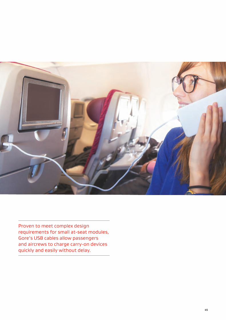
Proven to meet complex design requirements for small at-seat modules, Gore’s USB cables allow passengers and aircrews to charge carry-on devices quickly and easily without delay.
45

GORE® Aerospace High Speed Data Cables
46
GORE® HDMI Cables (1.4 Cat2 / 2.0 Versions)Gore’s cable bundles support 4K (2160p) video resolution, which is 4 times the clarity of 1080p for a richer viewing experience on cockpit and cabin displays. They provide outstanding signals for high-speed data transmission up to 18 Gb over the aircraft’s lifetime (Table 21). Passengers and flight crews can view IFE and critical information on crystal clear, high definition aircraft displays.
Also, Gore’s low-weight construction enables a smaller cable diameter that increases flexibility with a tighter bend radius for less complicated routing in tiny spaces of new and existing aircraft (Figure 35).
Typical Applications
▪ Digital video systems ▪ Electronic flight bag (EFB) ▪ Flight management systems ▪ Glass cockpits ▪ In-flight entertainment (IFE) systems
▪ Portable electronic devices ▪ Weather mapping
Standards Compliance
▪ ABD0031 (AITM 2.0005); BSS7230; FAR Part 25, Appendix F, Part I: Flammability
▪ ABD0031 (AITM 3.0005); BSS7239: Toxicity
▪ ABD0031 (AITM 3.0008B); BSS7238; FAR Part 25, Appendix F, Part V: Smoke Density
▪ ANSI/NEMA WC 27500: Environmental Testing, Jacket and Marking
▪ SAE AS4373™: Test Methods for Insulated Electric Wire (Contact Gore for available data)
Table 21: Cable Properties
ElectricalProperty Value
Standard Impedance (Ohms) 100 ± 10
Typical Operating Voltage (V) < 15
Nominal Velocity of Propagation (%) 80
Nominal Time Delay ns/m (ns/ft) 4.10 (1.25)
Capacitance pF/m (pF/ft) 230.0 (70.0)
Maximum Skew Within Pair ps/m (ps/ft) 15.0 (4.6)
Dielectric Withstanding Voltage (Vrms) Conductor-to-Conductor Conductor-to-Shield
15001000
Mechanical / EnvironmentalProperty Value
Jacket Material Engineered Fluoropolymer
Jacket Color Gray
Conductor Silver-Plated Copper/SPC Alloy
Conductor Color-Coding
High-Speed Pairs: Blue/White, Brown/White, Green/White, Red/White
Singles: Orange, Violet, White, Yellow
Triad: Gray, Pink, Tan
Dielectric Material ePTFE/PTFE
Temperature Range (°C) -65 to +200
47
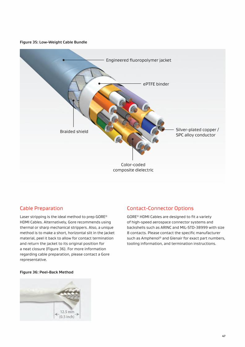
Figure 35: Low-Weight Cable Bundle
Cable PreparationLaser stripping is the ideal method to prep GORE® HDMI Cables. Alternatively, Gore recommends using thermal or sharp mechanical strippers. Also, a unique method is to make a short, horizontal slit in the jacket material, peel it back to allow for contact termination and return the jacket to its original position for a neat closure (Figure 36). For more information regarding cable preparation, please contact a Gore representative.
Contact-Connector OptionsGORE® HDMI Cables are designed to fit a variety of high-speed aerospace connector systems and backshells such as ARINC and MIL-STD-38999 with size 8 contacts. Please contact the specific manufacturer such as Amphenol® and Glenair for exact part numbers, tooling information, and termination instructions.
Figure 36: Peel-Back Method

48
GORE® HDMI Cables (1.4 Cat2 / 2.0 Versions)
Table 22: Cable Characteristics
Gore Part Number
AWG Size (Stranding)
Nominal Outer
Diameter mm (in)
Minimum Bend
Radius mm (in)
Nominal Weight kg/km
(lb/1000 ft)
Typical Insertion LossdB/5 m (16.4 ft)
1 GHz 2 GHz 3 GHz
RCN9121
Data/Drains/Discrete Pairs: 26 (19/38)
Capacitance-Controlled Singles: 28 (19/40)
6.6 (0.26) 13.0 (0.51) 77.5 (52.0) 4.9 8.5 12.0
Ordering InformationGORE® HDMI Cables are available in a standard size (Table 22). Visit gore.com/cable-distributors for the list of distributors. In addition, see page 72 regarding Gore’s full inventory of sample products and lead times.
For more information or to discuss specific characteristic limits and application needs, please contact a Gore representative. Also, see page 68 regarding Gore’s HDMI cable packaged with GORE™ High Abrasion Jacket System.

49
Passengers and flight crews can view in-flight entertainment and critical information on crystal clear, high definition aircraft displays.

GORE® Aerospace High Speed Data Cables
50
GORE® DVI Cables (Digital Only)
Typical Applications
▪ Cockpit displays ▪ Flight crew workstations ▪ Flight management systems ▪ In-flight entertainment (IFE) systems
▪ Weather mapping
Standards Compliance
▪ ABD0031 (AITM 2.0005); BSS7230; FAR Part 25, Appendix F, Part: Flammability
▪ ABD0031 (AITM 3.0005); BSS7239: Toxicity
▪ ABD0031 (AITM 3.0008B); BSS7238; FAR Part 25, Appendix F, Part V: Smoke Density
▪ ANSI/NEMA WC 27500: Environmental Testing, Jacket and Marking
▪ SAE AS4373™: Test Methods for Insulated Electric Wire (Contact Gore for available data
Gore’s single-link cables are built specifically for the digital component of DVI (digital video interface) systems. They deliver exceptional signal quality supporting the highest video resolution for optimal viewing on cockpit and cabin displays (Table 23). These cables meet stringent requirements for impedance control, insertion loss, skew, and EMI shielding necessary for reliable cable performance in aircraft DVI systems operating in demanding radar environments.
Additionally, Gore’s cable technology is smaller, lighter weight and more flexible without sacrificing robustness. These versatile cables also enable responsible termination with leading aerospace connector systems.
Gore’s cables are ideally suited for standard DVI harness configurations installed in aircraft (Figure 37). Design engineers no longer have to worry about designing harnesses with digital components that are ultimately inadequate for aircraft environments.
Table 23: Cable Properties
ElectricalProperty Value
Standard Impedance (Ohms) 100 ± 10
Typical Operating Voltage (V) < 15
Nominal Velocity of Propagation (%) 80
Nominal Time Delay ns/m (ns/ft) 4.07 (1.24)
Capacitance pF/m (pF/ft) 40.0 (12.0)
Maximum Skew ps/m (ps/ft) Pair-to-Pair Within Pair
52.50 (16.0)13.12 (4.0)
Dielectric Withstanding Voltage (Vrms) Conductor-to-Conductor Conductor-to-Shield
15001000
Mechanical / EnvironmentalProperty Value
Jacket Material Engineered Fluoropolymer
Jacket Color White (Laser Markable)
Conductor Silver-Plated Copper Alloy
Conductor Color-CodingBlue/White, Brown/White,
Green/White, Orange/White
Dielectric Material ePTFE/PTFE
Temperature Range (°C) -65 to +200

51
Figure 37: : Standard DVI Harness Cross-Section
Cable PreparationLaser stripping is the ideal method to prep GORE® DVI Cables. Alternatively, Gore recommends using thermal or sharp mechanical strippers. Also, a unique method is to make a short, horizontal slit in the jacket material, peel it back to allow for contact termination and return the jacket to its original position for a neat closure (Figure 38). For more information regarding cable preparation, please contact a Gore representative.
Contact-Connector OptionsGORE® DVI Cables are designed to fit a variety of high-speed aerospace connector systems and backshells such as ARINC and MIL-STD-38999 with size 8 contacts. Please contact the specific manufacturer such as Amphenol® and Glenair for exact part numbers, tooling information, and termination instructions.
Figure 38: Peel-Back Method

52
Table 24: Cable Characteristics
Gore Part Number
AWG Size (Stranding)
Nominal Outer
Diameter mm (in)
Minimum Bend
Radius mm (in)
Nominal Weight kg/km
(lb/1000 ft)
Typical Insertion LossdB/100 m (328 ft)
100 MHz
200 MHz
500 MHz
1 GHz
GSC-01-85249-24S 24 (19/36) 8.3 (0.33) 42.0 (1.65) 121.0 (81.31) 19.4 28.2 46.0 68.2
Ordering InformationGORE® DVI Cables are available in a standard size (Table 24). Visit gore.com/cable-distributors for the list of distributors. For more information or to discuss specific characteristic limits and application needs, please contact a Gore representative.
Exceptional Signal QualityGore evaluated the eye pattern of their 5-m (16-ft) DVI digital only cable to ensure the consistency of signal quality and transmission. The diamond-shaped eye mask shown in Figure 39 indicates the minimum receiver sensitivity specified by DVI Revision 1.0. Results showed that GORE® DVI Cables passed the eye mask test.
0 199Rise Time (ps)
1990.330
3002500
0
-300
Am
plitude (mV)
Figure 39: Eye Pattern of Gore’s DVI Cable
GORE® DVI Cables (Digital Only)

53
Gore’s single-link DVI cables support the highest video resolution for optimal viewing on aircraft displays in cockpits, cabins and flight crew workstations.

GORE® Aerospace High Speed Data Cables
54
GORE® Fiber Optic Cables (1.8 mm Simplex)
Typical Applications
▪ Avionics networks ▪ Cabin/flight management systems
▪ Digital video systems ▪ Ethernet backbone ▪ In-flight entertainment (IFE) systems
▪ Transceivers ▪ Weather radar systems
Standards Compliance
▪ ABD0031 (AITM 2.0005); BSS7230; FAR Part 25, Appendix F, Part I: Flammability
▪ ABD0031 (AITM 3.0008B); BSS7238; FAR Part 25, Appendix F, Part V: Smoke Density
▪ ARINC 802-2; Performance Requirements (GSC-13-84639, GSC-13-84640, GSC-13-84943)
▪ BSS7239: Toxicity
▪ EN3745-513; JN1177: Test methods for crush resistance (GSC-13-84943-07)
Gore’s most popular Simplex cables can easily accommodate the aerospace industry’s bandwidth-intensive requirements in a robust package compared to standard alternatives (Table 25). This version is offered in a range of single-mode and multi-mode core types that support the next generation of aircraft data architecture.
The innovative buffering system in the construction of this Simplex version is proven to resist high impact, crushing, abrasion, vibration, shock, and kinking while maintaining reliable signals (Figure 40). The combination of Gore’s unique cable materials also increases fiber movement under compression that improves termination with standard aerospace connector systems.
With an exceptional balance of properties, Gore’s 1.8 mm Simplex cables deliver improved reliability and longevity in a more robust construction without sacrificing size or weight.
Table 25: Cable Properties
ElectricalProperty Value
Maximum Optical Loss at 850 nm (dB/km)
4.0
Maximum Optical Loss at 1310 nm (dB/km)
3.0
Mechanical / EnvironmentalProperty Value
Jacket Material PFA
Core TypeSingle Mode or
Multi-Mode, Graded Index
Coating Type High-Temperature Acrylate
Buffering System ePTFE
Temperature Range (°C) -65 to +135

55
Figure 40: Crush-Resistant Layers
Contact-Connector OptionsGORE® Fiber Optic Cables (1.8 mm Simplex) are designed to fit a variety of high-speed aerospace connector systems and backshells such as ARINC, MIL-STD-38999, and MIL-PRF-29504. Please contact the specific manufacturer such as Amphenol®, COTSWORKS®, Glenair, and Radiall for exact part numbers, tooling information, and termination instructions.

56
Enhanced Crush ProtectionGore evaluated the durability of GORE® Fiber Optic Cables, 1.8 mm Simplex compared to a leading alternative cable using EN3745 method 513. Results showed that Gore’s cable far exceeded the minimum weight impact requirements for enhanced crush protection (Figures 41 and 42). The unique construction of Gore’s cables allows for lower force to move the fiber under compression while still maintaining excellent signal transmission. In contrast, the alternative cable showed significant optical loss under impact and failed to meet the industry specification.
Time (min)
Opt
ical
Los
s (d
B)
1.2
1
0.8
0.6
0.4
0.2
0 1 2 30
4 5 6 7 8 9 10 11 12 13 14 15 16 17 18 19 20 21
Forc
e (N
)
500
400
300
200
100
0
Bett
er P
erfo
rman
ce
Greater Crush Resistance at 850 nm
Force
AlternativeCable
IndustrySpec.
GORE® FiberOptic Cables
Time (min)
Opt
ical
Los
s (d
B)
1.2
1
0.8
0.6
0.4
0.2
0 1 2 30
4 5 6 7 8 9 10 11 12 13 14 15 16 17 18 19 20 21
Forc
e (N
)
500
400
300
200
100
0
Greater Crush Resistance at 1300 nm
Bett
er P
erfo
rman
ce
Force
AlternativeCable
IndustrySpec.
GORE® FiberOptic Cables
Figure 41: Crush Resistance at 850 nm
Figure 42: Crush Resistance at 1300 nm
GORE® Fiber Optic Cables (1.8 mm Simplex)
57
Time (min)
Opt
ical
Los
s (d
B)
0.50.4
0.20.1
0.3
0
-0.2-0.1
-0.3-0.4
0 50-0.5
100 150 200 250 300 350
Vibration Resistance at 850 nm (-40°C)
Sample 3
Sample 2
Sample 1
Sample 6
Sample 5
Sample 4
Industry Spec.
Time (min)
Opt
ical
Los
s (d
B)
0.50.4
0.20.1
0.3
0
-0.2-0.1
-0.3-0.4
0 50-0.5
100 150 200 250 300 350
Vibration Resistance at 1300 nm (135°C)
Sample 3
Sample 2
Sample 1
Sample 6
Sample 5
Sample 4
Industry Spec.
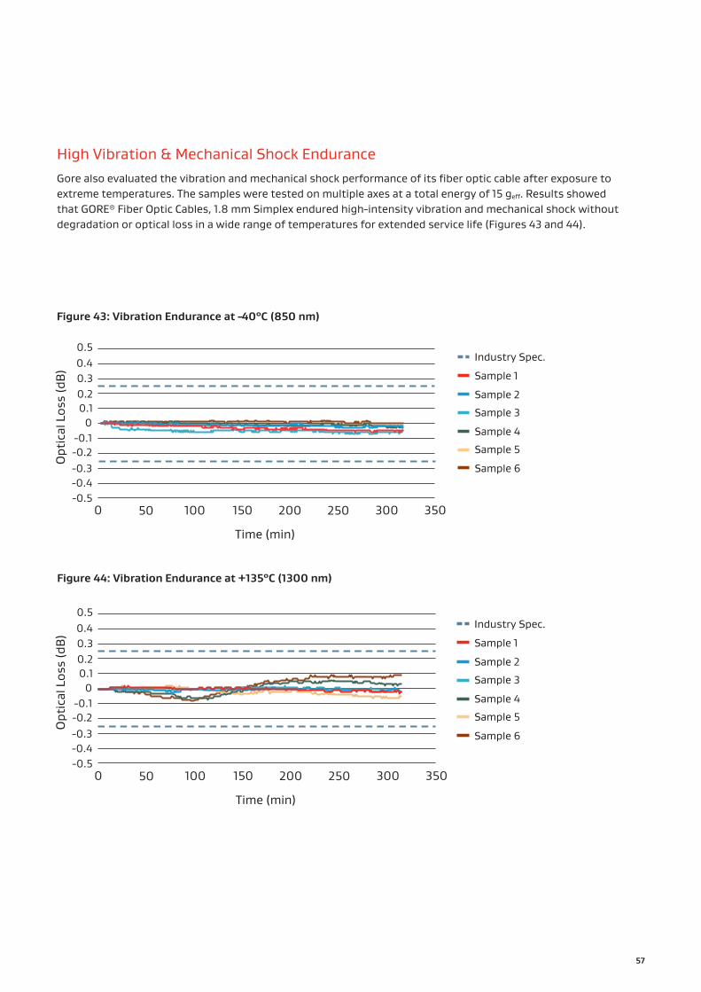
High Vibration & Mechanical Shock Endurance Gore also evaluated the vibration and mechanical shock performance of its fiber optic cable after exposure to extreme temperatures. The samples were tested on multiple axes at a total energy of 15 geff. Results showed that GORE® Fiber Optic Cables, 1.8 mm Simplex endured high-intensity vibration and mechanical shock without degradation or optical loss in a wide range of temperatures for extended service life (Figures 43 and 44).
Figure 43: Vibration Endurance at -40°C (850 nm)
Figure 44: Vibration Endurance at +135°C (1300 nm)

58
GORE® Fiber Optic Cables (1.8 mm Simplex)
Table 26: Cable Characteristics
Gore Part Number Core Type
Core/Cladding/Coating
Jacket Color
Nominal Outer
Diametermm (in)
MinimumBend
Radiusmm (in)
Nominal Weight
g/m
Maximum Tensile
Strength N
GSC-13-84689-04 SM (Single Mode) 9/125/245 Yellow 1.8 (0.07) 18.0 (0.71) 4.0 150
GSC-13-84689-07 SM (Single Mode) 9/125/245 Violet 1.8 (0.07) 18.0 (0.71) 4.0 150
GSC-13-84640-04OM1 (Multi-Mode,
Graded Index)62.5/125/245 Yellow 1.8 (0.07) 18.0 (0.71) 4.0 200
GSC-13-84640-07OM1 (Multi-Mode,
Graded Index)62.5/125/245 Violet 1.8 (0.07) 18.0 (0.71) 4.0 200
GSC-13-84639-04OM2 (Multi-Mode,
Graded Index)50/125/245 Yellow 1.8 (0.07) 18.0 (0.71) 4.0 200
GSC-13-84639-07OM2 (Multi-Mode,
Graded Index)50/125/245 Violet 1.8 (0.07) 18.0 (0.71) 4.0 200
GSC-13-84943-04OM3 (Multi-Mode,
Graded Index)50/125/245 Yellow 1.8 (0.07) 18.0 (0.71) 4.0 200
GSC-13-84943-07OM3 (Multi-Mode,
Graded Index)50/125/245 Violet 1.8 (0.07) 18.0 (0.71) 4.0 200
GSC-13-85423-04OM4 (Multi-Mode,
Graded Index)50/125/245 Yellow 1.8 (0.07) 18.0 (0.71) 4.0 200
GSC-13-85423-07OM4 (Multi-Mode,
Graded Index)50/125/245 Violet 1.8 (0.07) 18.0 (0.71) 4.0 200
GSC-13-85868-04OM5 (Multi-Mode,
Graded Index)50/125/245 Yellow 1.8 (0.07) 18.0 (0.71) 4.0 200
GSC-13-85868-07OM5 (Multi-Mode,
Graded Index)50/125/245 Violet 1.8 (0.07) 18.0 (0.71) 4.0 200
Ordering InformationGORE® Fiber Optic Cables (1.8 mm Simplex) are available in standard sizes (Table 26). Visit gore.com/cable-distributors for the list of distributors. In addition, see page 72 regarding Gore’s full inventory of sample products and lead times.
For more information or to discuss specific characteristic limits and application needs — including a bend-sensitive fiber option or particular fiberglass type, please contact a Gore representative.

59
Gore’s 1.8 mm Simplex fiber optic cable easily accommodates bandwidth-intensive connectivity requirements in a robust package without sacrificing size or weight.
GORE® Aerospace High Speed Data Cables
60
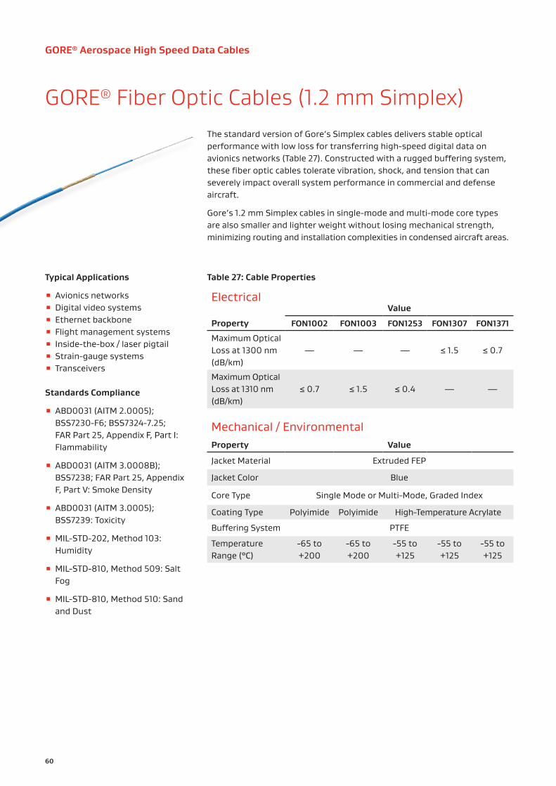
GORE® Fiber Optic Cables (1.2 mm Simplex)The standard version of Gore’s Simplex cables delivers stable optical performance with low loss for transferring high-speed digital data on avionics networks (Table 27). Constructed with a rugged buffering system, these fiber optic cables tolerate vibration, shock, and tension that can severely impact overall system performance in commercial and defense aircraft.
Gore’s 1.2 mm Simplex cables in single-mode and multi-mode core types are also smaller and lighter weight without losing mechanical strength, minimizing routing and installation complexities in condensed aircraft areas.
Typical Applications
▪ Avionics networks ▪ Digital video systems ▪ Ethernet backbone ▪ Flight management systems ▪ Inside-the-box / laser pigtail ▪ Strain-gauge systems ▪ Transceivers
Standards Compliance
▪ ABD0031 (AITM 2.0005); BSS7230-F6; BSS7324-7.25; FAR Part 25, Appendix F, Part I: Flammability
▪ ABD0031 (AITM 3.0008B); BSS7238; FAR Part 25, Appendix F, Part V: Smoke Density
▪ ABD0031 (AITM 3.0005); BSS7239: Toxicity
▪ MIL-STD-202, Method 103: Humidity
▪ MIL-STD-810, Method 509: Salt Fog
▪ MIL-STD-810, Method 510: Sand and Dust
Table 27: Cable Properties
ElectricalValue
Property FON1002 FON1003 FON1253 FON1307 FON1371
Maximum Optical Loss at 1300 nm (dB/km)
— — — ≤ 1.5 ≤ 0.7
Maximum Optical Loss at 1310 nm (dB/km)
≤ 0.7 ≤ 1.5 ≤ 0.4 — —
Mechanical / EnvironmentalProperty Value
Jacket Material Extruded FEP
Jacket Color Blue
Core Type Single Mode or Multi-Mode, Graded Index
Coating Type Polyimide Polyimide High-Temperature Acrylate
Buffering System PTFE
Temperature Range (°C)
-65 to +200
-65 to +200
-55 to +125
-55 to +125
-55 to +125

61
Table 28: Cable Characteristics
Gore Part Number Core Type
Core/Cladding/Coating
Nominal Outer
Diametermm (in)
MinimumBend Radius
mm (in)
Nominal Weight
g/m
Maximum Tensile
Strength N
FON1002 SM (Single Mode) 9/125/155 1.2 (0.04)≥ 12.0 (0.47)≥ 25.0 (0.98)
2.5 350
FON1003OM1 (Multi-Mode,
Graded Index)62.5/125/155 1.2 (0.04)
≥ 12.0 (0.47)≥ 25.0 (0.98)
2.5 350
FON1253 SM (Single Mode) 9/125/250 1.2 (0.04)≥ 12.0 (0.47)≥ 25.0 (0.98)
2.5 350
FON1307OM2 (Multi-Mode,
Graded Index)50/125/250 1.2 (0.04)
≥ 12.0 (0.47)≥ 25.0 (0.98)
2.5 350
FON1371OM1 (Multi-Mode,
Graded Index)62.5/125/250 1.2 (0.04)
≥ 12.0 (0.47)≥ 25.0 (0.98)
2.5 350
Contact-Connector OptionsGORE® Fiber Optic Cables (1.2 mm Simplex) are designed to fit a variety of high-speed aerospace connector systems and backshells such as ARINC, MIL-STD-38999, and MIL-PRF-29504. Please contact the specific manufacturer such as Amphenol®, COTSWORKS®, Glenair, and Radiall for exact part numbers, tooling information, and termination instructions.
Ordering InformationGORE® Fiber Optic Cables (1.2 mm Simplex) are available in standard sizes (Table 28). Visit gore.com/cable-distributors for the list of distributors. In addition, see page 72 regarding Gore’s full inventory of sample products and lead times.
For more information or to discuss specific characteristic limits and application needs, please contact a Gore representative.

GORE® Aerospace High Speed Data Cables
62
GORE® Fiber Optic Cables (900 micron)This version of Gore’s fiber optic cables provides a high level of crush protection similar to the Simplex versions while drastically reducing shrink back and the time required to terminate samples. These single-mode and multi-mode cables deliver unfailing signal transmission with low optical loss in rigorous maintenance and flight conditions, ensuring lifetime performance and lower total costs (Table 29).
Gore’s 900-micron optical fiber cables incorporate smaller, lighter weight, and robust materials that are easy to route, making them an excellent choice for inside-the-box applications.
Typical Applications
▪ Inside-the-box ▪ Transceivers
Standards Compliance
▪ ABD0031 (AITM 2.0005); BSS7230; FAR Part 25, Appendix F, Part I: Flammability
▪ ABD0031 (AITM 3.0008B); BSS7238; FAR Part 25, Appendix F, Part V: Smoke Density
▪ ABD0031 (AITM 3.0005); BSS7239: Toxicity
▪ ARINC 802-2: Performance Requirements (GSC-13-85067-00)
Table 29: Cable Properties
ElectricalProperty Value
Maximum Optical Loss at 850 nm (dB/km)
3.0
Maximum Optical Loss at 1310 nm (dB/km)
1.0
Mechanical / EnvironmentalProperty Value
Jacket Material PEEK
Jacket Color Tan
Core Type Single Mode or Multi-Mode
Coating Type High-Temperature Acrylate
Buffering System ePTFE
Temperature Range (°C) -60 to +135

63
Table 30: Cable Characteristics
Gore Part Number Core Type
Core/Cladding/Coating
Nominal Outer
Diametermm (in)
MinimumBend Radius
mm (in)
Nominal Weight
g/m
Maximum Tensile
Strength N
GSC-13-85067-00 OM1 (Multi-Mode) 62.5/125/245 0.9 (0.35) 18.0 (0.71) 0.85 50
GSC-13-85424-00 OM4 (Multi-Mode) 50/125/245 0.9 (0.35) 18.0 (0.71) 0.85 50
GSC-13-85375-00 SM (Single Mode) 9/125/245 0.9 (0.35) 18.0 (0.71) 0.85 50
GSC-13-85869-00 OM5 (Multi-Mode) 50/125/245 0.9 (0.35) 18.0 (0.07) 0.85 50
Contact-Connector OptionsGORE® Fiber Optic Cables (900 micron) are designed to fit a variety of high-speed aerospace connector systems and backshells such as ARINC, MIL-STD-38999, and MIL-PRF-29504. Please contact the specific manufacturer such as Amphenol®, COTSWORKS®, Glenair, and Radiall for exact part numbers, tooling information, and termination instructions.
Ordering InformationGORE® Fiber Optic Cables (900 micron) are available in standard sizes (Table 30). Visit gore.com/cable-distributors for the list of distributors. In addition, see page 72 regarding Gore’s full inventory of sample products and lead times.
For more information or to discuss specific characteristic limits and application needs — including fiber options packaged with GORE® Cable Protection Systems for outside-the-box applications, please contact a Gore representative.

GORE® Aerospace High Speed Data Cables
64
GORE® Fiber Optic Ribbon CablesEngineered with a unique buffering system, Gore’s ribbon cables provide reliable protection in difficult environments while maintaining high-speed communications up to 12 channels on avionics digital networks. These multi-mode cables deliver consistent signal integrity with low optical loss for uninterrupted data transmission after installation and long after alternative cables have succumbed to harsh aircraft conditions (Table 31).
Also, the compact design of these cables increases flexibility with a small bend radius, which simplifies and speeds up the installation process in cramped areas of an aircraft.
Gore offers three versions of ribbon cables, each manufactured with the right amount of ruggedness to optimize performance in applications ranging from inside-the-box to outside the aircraft.
Typical Applications
▪ Avionics networks ▪ Digital video systems ▪ Ethernet backbone ▪ Flight management systems ▪ Transceivers ▪ Weather radar systems
Standards Compliance
▪ ABD0031 (AITM 2.0005); BSS7230; FAR Part 25, Appendix F, Part I: Flammability
▪ ABD0031 (AITM 3.0008B); BSS7238; FAR Part 25, Appendix F, Part V: Smoke Density
▪ ABD0031 (AITM 3.0005); BSS7239: Toxicity
▪ MIL-STD-202, Method 103: Humidity
▪ MIL-STD-810, Method 509: Salt Fog
▪ MIL-STD-810, Method 510: Sand and Dust
Table 31: Cable Properties
ElectricalValue
Property FOA8100/6/12/1 FON1214/4/12 FON1256/4/12 FON1551
Maximum Optical Loss at 850 nm (dB/km)
≤ 2.3 ≤ 4.0 ≤ 2.3 ≤ 3.5
Mechanical / EnvironmentalProperty Value
Jacket Material PVDF Engineered Fluoropolymer PVDF
Core Type Multi-Mode or Multi-Mode, Graded Index
Coating Type Acrylate
High-Temperature
AcrylateAcrylate Acrylate
Buffering System PTFE
Temperature Range (°C) -60 to +125 -55 to +125 -60 to +85 -55 to +125

65
Contact-Connector OptionsGORE® Fiber Optic Ribbon Cables are designed to fit a variety of standard high-speed aerospace MT connector systems and backshells. Please contact the specific manufacturer such as Amphenol®, COTSWORKS®, Glenair, and Radiall for exact part numbers, tooling information, and termination instructions.
Ordering InformationGORE® Fiber Optic Ribbon Cables are available in standard sizes (Table 32). Visit gore.com/cable-distributors for the list of distributors. In addition, see page 72 regarding Gore’s full inventory of sample products and lead times.
For more information or to discuss specific characteristic limits and application needs — including other fiber options and core types, please contact a Gore representative.
Table 32: Cable Characteristics
Gore Part Number Core Type
Core/Cladding/Coating
Jacket Color
Nominal Outer
Diametermm (in)
MinimumBend Radius
mm (in)
Nominal Weight
g/m
Maximum Tensile
Strength N
FOA8100/6/12/1 OM3 (Multi-Mode) 50/125/245 Orange 5.1 (0.20)≥ 12.0 (0.47)≥ 25.0 (0.98)
2.0 350
FON1214/4/12OM2 (Multi-Mode,
Graded Index)50/125/245 White 3.6 (0.14)
≥ 12.0 (0.47)≥ 25.0 (0.98)
2.0 350
FON1256/4/12 OM3 (Multi-Mode) 50/125/245 White 3.6 (0.14)≥ 12.0 (0.47)≥ 25.0 (0.98)
2.0 350
FON1551OM2 (Multi-Mode,
Graded Index)50/125/245 Orange 3.8 (0.15)
≥ 6.0 (0.24) ≥ 13.0 (0.51)
2.0 350

GORE® Aerospace High Speed Data Cables
66
GORE® Cable Protection SystemsBuilt with crush- and abrasion-resistant materials, Gore’s durable cable systems provide some of the highest levels of protection available in the industry today (Table 33). They meet the demands of aircraft OEMs and system suppliers requiring more protection for packaging copper wires and fiber optics in small, lightweight and routable designs. These cable protection systems can routinely tolerate complicated routing and harsh flight conditions such as fluctuating temperatures and severe vibration.
Quick & Easy InstallationWithin GORE® Cable Protection Systems, copper and fiber can float freely without getting damaged during installation in cable runs and sharp edges in airframes. Gore’s highly flexible designs offer tighter bending capability that allows copper and fiber to be routed without exceeding the minimum bend radius eliminating over bending. Installers will find it quicker and easier to route copper and fiber packaged with Gore’s cable protection systems in less space without having to worry about breakage or failure.
Standards Compliance
▪ ABD0031 (AITM 2.0005); BSS7230; FAR Part 25, Appendix F, Part I: Flammability
▪ ABD0031 (AITM 3.0005); BSS7239: Toxicity
▪ ABD0031 (AITM 3.0008B); BSS7238; FAR Part 25, Appendix F, Part V: Smoke Density
▪ SAE AS81914™/1-6: Plastic Convoluted Tubing Requirements
Table 33: Cable System Properties
Mechanical / EnvironmentalProperty Value
Jacket Material ePTFE/PTFE
Jacket Color Black with Violet Stripes
Temperature Range (°C) -65 to +260

67
Contact-Connector OptionsGORE® Cable Protection Systems are designed to fit a variety of high-speed aerospace connector systems and backshells such as MIL-STD-38999 and M85049. Please contact the specific manufacturer such as Amphenol®, COTWORKS® and Glenair for exact part numbers, tooling information, and termination instructions.
Ordering InformationGORE® Cable Protection Systems are available in standard sizes (Table 34). Visit gore.com/cable-distributors for the list of distributors.
For more information or to discuss specific characteristic limits and application needs regarding Gore’s full portfolio of high-speed data cables packaged with GORE® Cable Protection Systems, please contact a Gore representative.
Table 34: Cable System Characteristics
Gore Part Number
Overall Sizemm (in)
Minimum Inner Diameter
mm (in)
MaximumDiametermm (in)
MinimumBend Radius
mm (in)
Nominal WeightKg/km
(lb/1000 ft)
FON1594 7.0 (0.28) 3.3 (0.13) 7.2 (0.29) 7.6 (0.30) 25.0 (37.2)
FON1580 9.0 (0.35) 4.6 (0.18) 9.4 (0.37) 10.2 (0.40) 36.0 (54.0)
FON1599 18.0 (0.71) 12.0 (0.47) 18.0 (0.71) 19.1 (0.75) 112.0 (75.0)

GORE® Aerospace High Speed Data Cables
68
GORE® Abrasion Resistant Cable Jacket
Standards Compliance
▪ ABD0031 (AITM 2.0005); BSS7230; FAR Part 25, Appendix F, Part I: Flammability
▪ ABD0031 (AITM 3.0008B); BSS7238; FAR Part 25, Appendix F, Part V: Smoke Density
▪ ABD0031 (AITM 3.0005); BSS7239: Toxicity
▪ EN3475-503: Test Methods for Scrape Abrasion
▪ SAE AS4373™: Test Methods for Insulated Electric Wire (Contact Gore for available data)
Proven Superior Cut-Through ResistanceUsing SAE AS4373™ method 703, Gore compared 100-ohm quadrax cables packaged with 4 different jacket types. Results indicated that GORE® Abrasion Resistant Cable Jacket drastically outperformed PFA and FEP materials for superior cut-through resistance at high temperatures (Figure 45).
Testing proved that Gore’s pioneering cable jacket can tolerate extreme aircraft conditions and complex routing without cracking or splitting, ensuring copper wires transmit data reliably in the intended application.
Engineered with a revolutionary fluoropolymer fiber material, Gore’s cable jacket is proven to meet new stringent industry standards for durability without sacrificing size, weight or electrical performance (Table 35).
This rugged cable jacket is extremely abrasion resistant and meets EN3475-503 requirements. It eliminates the need for additional protective sleeving now required for copper cables installed in cockpit and cabin seats. Gore’s state-of-the-art cable technology is thinner, lighter and more flexible with tighter bendability for straightforward routing and expedited installation in narrow seat configurations.
GORE® Abrasion Resistant Cable Jacket ensures all-around, lifetime mechanical protection and is ideal for packaging copper cables that support the latest standardized high data rate protocols such as HDMI and more.
Temperature (°C)
Forc
e to
Fai
lure
(lb)
350
300
250
200
150
100
50
23 700
150
FEP JacketPFA JacketGore Standard Jacket System
GORE® Abrasion Resistant Cable Jacket
Cut-Through Resistance at Temperature
Figure 45: Cut-Through Resistance at High Temperatures

69
Table 35: Cable Properties
Typical values are based on GORE® HDMI Cables (2.0 Version) packaged with GORE® Abrasion Resistant Cable Jacket.
ElectricalProperty Value
Standard Impedance (Ohms) 100 ± 10
Typical Operating Voltage (V) < 15
Nominal Velocity of Propagation (%) 80
Nominal Time Delay ns/m (ns/ft) 4.10 (1.25)
Capacitance pF/m (pF/ft) 230.0 (70.0)
Maximum Skew Within Pair ps/m (ps/ft) 15.0 (4.6)
Dielectric Withstanding Voltage (Vrms) Conductor-to-Conductor Conductor-to-Shield
15001000
Mechanical / EnvironmentalProperty Value
Jacket Material Engineered Fluoropolymer Fiber Braid
Jacket Color Black
Conductor Silver-Plated Copper/SPC Alloy
Conductor Color-Coding
High-Speed Pairs: Blue/White, Brown/White, Green/White, Red/White
Singles: Orange, Violet, White, Yellow
Triad: Gray, Pink, Tan
Dielectric Material ePTFE/PTFE
Cut-Through Resistance kg (lb) (SAE AS4373™- 703) 23°C 70°C 150°C
122 (270)73 (160)59 (130)
Scrape Abrasion Resistance (Cycles) (EN3475-503) 30°C & 55°C / F = 1.2 daN
> 8,000
Temperature Range (°C) -65 to +200

70
Ordering InformationGORE® HDMI Cables (2.0 Version) packaged with GORE® Abrasion Resistant Cable Jacket is available in a standard size (Table 36). Visit gore.com/cable-distributors for the list of distributors.
For more information or to discuss specific characteristic limits and application needs regarding Gore’s full portfolio of high-speed data cables packaged with GORE® Abrasion Resistant Cable Jacket, please contact a Gore representative.
Table 36: Cable Characteristics
HDMI 2.0 Version
Gore Part Number
AWG Size (Stranding)
Nominal Outer
Diameter mm (in)
Minimum Bend
Radius mm (in)
Nominal Weight kg/km
(lb/1000 ft)
Typical Insertion LossdB/30 m (100 ft)
825 MHz
2475 MHz
4125 MHz
5100 MHz
RCN9195 Data/Drains/Discrete Pairs: 26 (19/38)
Capacitance-Controlled Singles: 28 (19/40)
6.6 (0.26) 13.0 (0.51) 77.5 (52.0) 5.0 12.0 20.0 25.0
GORE® Abrasion Resistant Cable Jacket

71
Proven to meet new stringent requirements, Gore’s cable jacket with abrasion resistance eliminates the need for protective sleeving now required for copper cables installed in cockpit and cabin seats.

GORE® Aerospace High Speed Data Cables
72
Sample Product InventoryComplimentary samples of Gore’s pre-qualified high data rate copper and fiber optic cables are available with short lead times (Tables 37 and 38). Gore can ship samples within 2 business days (48 hours) from the date of the request.
As a result, aircraft OEMs can validate and support low-rate production using Gore’s standard products in their specific application with lower technical and business risks to their programs.
Prototyping & EvaluationVisit gore.com/highdataratesample to fill out the short online form and receive your complimentary samples. Alternatively, contact a Gore representative regarding available materials for your sample, prototype, and small production requirements.
Table 37: Inventory of Gore’s Standard Copper Cables
Cable Type / Protocol ConstructionStandard Impedance
(Ohms) Gore Part Number
Ethernet (Cat5e/6/6a)
4 Pairs (24 AWG) 100 RCN9034-24
4 Pairs (26 AWG) 100 RCN9047-26
4 Pairs (28 AWG) 100 RCN9034-28
4 Pairs (24 AWG)a 100 RCN8966-24
4 Pairs (26 AWG)a 100 RCN8966-26
Ethernet (Cat5e) 2 Pairs (26 AWG) 100 RCN9133-26
Ethernet (Cat5e)Quadrax (24 AWG) 100 GSC-03-84608-00
Quadrax (26 AWG) 100 GSC-03-84820-00
Quadrax (Speciality)
Quadrax (24 AWG) 100 RCN8752
Quadrax (26 AWG) 100 RCN8982
Quadrax (28 AWG) 100 RCN8973
FireWire® (IEEE 1394b)
Quadrax (22 AWG) 110 RCN8645
Quadrax (24 AWG) 110 RCN8647
Quadrax (26 AWG) 110 RCN8652
Fibre Channel Quadrax (26 AWG) 150 RCN8328
a. See table 3 (page 10) for Ethernet interconnect options.

73
Table 37: Inventory of Gore’s Standard Copper Cables (continued)
Cable Type / Protocol ConstructionStandard Impedance
(Ohms) Gore Part Number
Shielded Twisted Pair
Single Pair (20 AWG) 100 DXN2600
Single Pair (22 AWG) 100 DXN2601
Single Pair (24 AWG) 100 DXN2602
Single Pair (26 AWG) 100 DXN2603
Single Pair (28 AWG) 100 DXN2604
Single Pair (30 AWG) 100 DXN2605
Single Pair (32 AWG) 100 DXN2606
CAN Bus Single Pair (24 AWG) 120 GSC-03-85752-24D
USB (2.0)
Data/Power (22 AWG) 90 RCN8800-22D-22P-H
Data (24 AWG)Power (22 AWG)
90 RCN8800-24D-22P-H
Data (26 AWG)Power (24 AWG)
90 RCN8800-26D-24P-H
USB (3.1)Data (26 AWG)
Power (24 AWG)90 GSC-03-84761-24D
HDMI (2.0) Hybrid 100 RCN9121
Table 38: Inventory of Gore’s Standard Fiber Optic Cables
Cable Type / Protocol Construction Core/Cladding/Coating Gore Part Number
Simplex
1.8 mm, OM1 62.5/125/245 GSC-13-84640-07
1.8 mm, OM2 50/125/245 GSC-13-84639-07
1.8 mm, OM3 50/125/245 GSC-13-84943-07
1.8 mm, OM4 50/125/245 GSC-13-85423-07
Simplex 1.2 mm, OM2 50/125/250 FON1307
Simplex 900 micron, OM1 62.5/125/245 GSC-13-85067-00
Ribbon12 fiber, OM2 50/125/245 FON1214/4/12
12 fiber, OM3 50/125/245 FON1256/4/12

W. L. Gore & Associates, Inc.555 Paper Mill Road, Newark, DE 19711 UNITED STATEST +1 800 626 7708 F +1 302 738 7710 gore.com/highdatarateaircraftcables
ACS
-040
4-D
AT-U
S-R
3-A
UG
19
Information in this publication corresponds to W. L. Gore & Associates’ current knowledge on the subject. It is offered solely to provide possible suggestions for user experimentations. It is NOT intended, however, to substitute for any testing the user may need to conduct to determine the suitability of the product for the user’s particular purposes. Due to the unlimited variety of potential applications for the product, the user must BEFORE production use, determine that the product is suitable for the intended application and is compatible with other component materials. The user is solely responsible for determining the proper amount and placement of the product. Information in this publication may be subject to revision as new knowledge and experience become available. W. L. Gore & Associates cannot anticipate all variations in actual end user conditions, and therefore, makes no warranties and assumes no liability in connection with any use of this information. No information in this publication is to be considered as a license to operate under or a recommendation to infringe any patent right.
NOTICE — USE RESTRICTIONS APPLY. Not for use in food, drug, cosmetic or medical device manufacturing, processing, or packaging operations.
Amphenol is a registered trademark of Amphenol Corporation. CeeLok FAS-T and FAS-X are registered trademarks of TE Connectivity. COTSWORKS is a trademark of COTSWORKS, LLC. El Ochito is a registered trademark of Glenair, Inc. EZ-RJ45 is a registered trademark of Platinum Tools. FireWire is a registered trademark of Apple, Inc., in the U.S. and other countries. HARTING RJ Industrial is a registered trademark of HARTING Technology Group. ITT and Cannon are registered trademarks of ITT Inc. LEMO is a registered trademark of LEMO SA. Micro 360 is a registered trademark of Omnetics Connector Corporation. Octax is a registered trademark of Carlisle Interconnect Technologies. Sentinel is a registered trademark of Sentinel Connector Systems, Inc.
GORE, Together, improving life, and designs are trademarks of W. L. Gore & Associates, Inc. © 2019 W. L. Gore & Associates, Inc.