Total energy optimization in F3J glider towing
9
Total energy optimization in F3J glider towing Francesco Meschia April, 2014 1 Motion of the glider We will study the equations of motion for the glider in a reference frame in which the z axis is aligned with the direction that passes through the glider tow hook and through the point in which the tow line meets the towing equipment, and the x axis is perpendicular to z and points into the direction of motion. If we assume gravity force to be negligible in comparison with the aero- dynamic forces during tow, and if we assume that the airmass in which the glider is towed is not moving in the ground reference frame, then the motion of the glider during tow is purely a ”glide” in the x, z plane, determined by the pull of the tow line and by the aerodynamic forces. It must be noted that the drag from the towline is not negligible during tow, as it can amount to as much as the drag of the airframe itself. 1.1 Drag from the tow line Given a line of length L and diameter φ, fixed at one end and with the other end moving with velocity v, the aerodynamic drag experienced by the infinitesimal line element, having length dl and at a distance l from the pivot is: (1) dD line = 1 2 ρφ dl C D line v · l L 2 The total drag force experienced by the line can be found by integrating along the whole line: (2) D line = 1 2 ρφC D line v 2 L 2 Z L 0 l 2 dl = 1 2 ρφL 1 3 C D line v 2 1
-
Upload
francesco-meschia -
Category
Sports
-
view
150 -
download
1
Transcript of Total energy optimization in F3J glider towing
Total energy optimization in F3J glider towing
Francesco Meschia
April, 2014
1 Motion of the glider
We will study the equations of motion for the glider in a reference framein which the z axis is aligned with the direction that passes through theglider tow hook and through the point in which the tow line meets thetowing equipment, and the x axis is perpendicular to z and points into thedirection of motion.
If we assume gravity force to be negligible in comparison with the aero-dynamic forces during tow, and if we assume that the airmass in which theglider is towed is not moving in the ground reference frame, then the motionof the glider during tow is purely a ”glide” in the x, z plane, determined bythe pull of the tow line and by the aerodynamic forces.
It must be noted that the drag from the towline is not negligible duringtow, as it can amount to as much as the drag of the airframe itself.
1.1 Drag from the tow line
Given a line of length L and diameter φ, fixed at one end and with theother end moving with velocity v, the aerodynamic drag experienced by theinfinitesimal line element, having length dl and at a distance l from the pivotis:
(1)dDline =1
2ρφ dl CDline
(v · lL
)2
The total drag force experienced by the line can be found by integratingalong the whole line:
(2)Dline =
1
2ρφCDline
v2
L2
∫ L
0l2 dl
=1
2ρφL
1
3CDline
v2
1

If we sum the drag components from the line and from the airframe, wehave:
(3)
D = Dline +Dglider
=1
2ρφL
1
3CDline
v2 +1
2ρSCDglider
v2
=1
2ρS
(φLCDline
3S+ CDglider
)v2
where we can assume CDline≈ 1.
1.2 Lift from the glider
The lift produced by the glider’s surfaces follows the usual equation:
(4)Lglider =1
2ρSCLglider
v2x
1.3 Traction from the tow line
The traction experienced by the glider depends on the characteristics of thetowing system. As we need to pick a mathematical model for it, we willassume a linear relation between traction and line retrieval rate. In thismodel, traction is at a maximum when retrieval rate is zero (stalled towingsystem), and decreases linearly to zero when line retrieval rate is maximum:
(5)T = Tmax
(1 − vr
vrmax
)1.4 Steady-state motion of the glider
In steady-state conditions, the glider does not accelerate or decelerate, andeffectively ”glides” in the x, z reference frame. Its airspeed components vxand vy are therefore constant, and they can be derived by imposing thecondition that aerodynamic reaction force must balance line traction:
(6)~R = ~L+ ~D
= −~T
For the sake of simplicity, we can neglect the drag component and assumethat the reaction force is composed by lift only:
(7)~R ≈ ~L
= −~T
2

If we replace the known expression for the magnitude of L, and the modelingwe introduced for T . In steady state conditions, the line retrieval rate isequivalent to the sinking speed of the glider, so vr = vz, and we obtain:
(8)1
2ρS C2
Lgliderv2x = Tmax
(1 − vz
vzmax
)Which can be solved to get vx as a function of vz and CLglider
. However,these variables are not independent, as we have vx = vz CLglider
/CDtot . If wesubstitute, we finally obtain:
(9)1
2ρS
C3Lglider
C2Dtot
v2z = Tmax
(1 − vz
vzmax
)Which can finally be solved for vz, giving one physically significant root:
(10)vz =−Tmaxvmax
+
√T 2maxv2max
+ 2ρS Tmax
C3Lglider
C2Dtot
ρSC3
Lglider
C2Dtot
This equation gives the retrieval rate (the sinking speed vz) as a functionof the traction modeling parameters and as a function of CL and CD (thatis, as a function of α). The complete speed polar can then be obtained bycalculating vx from vz as vx = vz CL/CD.
2 Energy of the system
In this section we will estimate the total energy of the system at the end ofthe tow.
2.1 Kinetic energy
The kinetic energy of the system is pretty straightforward. Assuming thatthe mass of the line is negligible, we will only consider the mass m of theglider. Under this hypothesis it is simply:
(11)Ekin =1
2m(v2x + v2z
)
3

2.2 Gravitational potential energy
Again, if we consider the mass m of the glider only, the gravitational po-tential energy of the system at the end of the tow (supposed to end whenthe glider is directly over the towing system, i.e. after a π/2 rad arc), witha line of length l is:
(12)Epot = mg l
(1 − vz
π
2 vx
)2.3 Elastic potential energy
Under the assumption that the towline, within the domain of intended use,is an elastic medium following Hooke’s law, the elastic potential energy ofthe line, when stretched under a force F , is:
(13)Eel =1
2
(Fel)2
kel
The elastic constant kel of the line can be calculated from its geometry andfrom the Young’s modulus EY of the material:
(14)kel =EY πφ
2
8 l
When we substitute for Fel the expression for traction force T , and enforcethe steady-state condition vr = vz, we obtain:
(15)Eel =4 l
EY πφ2
[Tmax
(1 − vz
vzmax
)]22.4 Total energy
If we sum up the kinetic, gravitational potential and elastic potential com-ponents, we have an expression for total energy:
Etot =1
2m(v2x + v2z
)+mg l
(1 − vz
π
2 vx
)+
4 l
EY πφ2
[Tmax
(1 − vz
vzmax
)]2(16)
4
1.5!
2!
2.5!
3!
3.5!
4!
4.5!
5!
15! 17.5! 20! 22.5! 25! 27.5! 30!
vz [m/s]!
v [m/s]!
700 J!500 J!300 J!
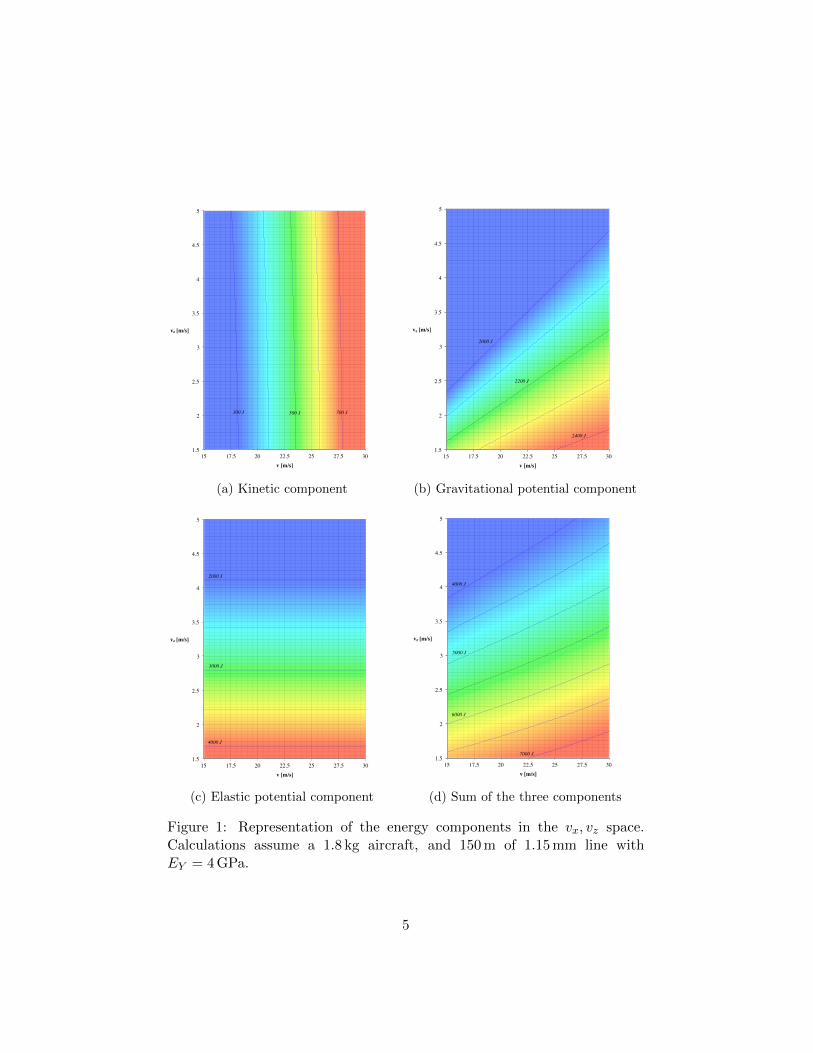
(a) Kinetic component
1.5!
2!
2.5!
3!
3.5!
4!
4.5!
5!
15! 17.5! 20! 22.5! 25! 27.5! 30!
vz [m/s]!
v [m/s]!
2400 J!
2200 J!
2000 J!
(b) Gravitational potential component
1.5!
2!
2.5!
3!
3.5!
4!
4.5!
5!
15! 17.5! 20! 22.5! 25! 27.5! 30!
vz [m/s]!
v [m/s]!
2000 J!
4000 J!
3000 J!
(c) Elastic potential component
1.5!
2!
2.5!
3!
3.5!
4!
4.5!
5!
15! 17.5! 20! 22.5! 25! 27.5! 30!
vz [m/s]!
v [m/s]!
5000 J!
6000 J!
7000 J!
4000 J!
(d) Sum of the three components
Figure 1: Representation of the energy components in the vx, vz space.Calculations assume a 1.8 kg aircraft, and 150 m of 1.15 mm line withEY = 4 GPa.
5
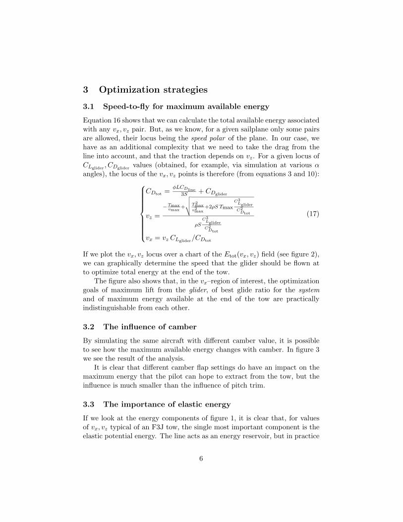
3 Optimization strategies
3.1 Speed-to-fly for maximum available energy
Equation 16 shows that we can calculate the total available energy associatedwith any vx, vz pair. But, as we know, for a given sailplane only some pairsare allowed, their locus being the speed polar of the plane. In our case, wehave as an additional complexity that we need to take the drag from theline into account, and that the traction depends on vz. For a given locus ofCLglider
, CDglidervalues (obtained, for example, via simulation at various α
angles), the locus of the vx, vz points is therefore (from equations 3 and 10):
(17)
CDtot =φLCDline
3S + CDglider
vz =
−Tmaxvmax
+
√√√√T2max
v2max+2ρS Tmax
C3Lglider
C2Dtot
ρSC3Lglider
C2Dtot
vx = vz CLglider/CDtot
If we plot the vx, vz locus over a chart of the Etot(vx, vz) field (see figure 2),we can graphically determine the speed that the glider should be flown atto optimize total energy at the end of the tow.
The figure also shows that, in the vx–region of interest, the optimizationgoals of maximum lift from the glider, of best glide ratio for the systemand of maximum energy available at the end of the tow are practicallyindistinguishable from each other.
3.2 The influence of camber
By simulating the same aircraft with different camber value, it is possibleto see how the maximum available energy changes with camber. In figure 3we see the result of the analysis.
It is clear that different camber flap settings do have an impact on themaximum energy that the pilot can hope to extract from the tow, but theinfluence is much smaller than the influence of pitch trim.
3.3 The importance of elastic energy
If we look at the energy components of figure 1, it is clear that, for valuesof vx, vz typical of an F3J tow, the single most important component is theelastic potential energy. The line acts as an energy reservoir, but in practice
6

1.5!
2!
2.5!
3!
3.5!
4!
4.5!
5!
15! 17.5! 20! 22.5! 25! 27.5! 30!
vz [m/s]!
v [m/s]!
5000 J!
4000 J!
6000 J!
7000 J!
Figure 2: Speed polar for a sample glider-and-line system (assumptions asin figure 1), subject to a traction force variable with vz, superimposed overa chart of the scalar field corresponding to the total energy available at theend of tow. Iso-energetic curves for a few energy levels are shown.
7

1.5!
2!
2.5!
3!
3.5!
4!
4.5!
5!
15! 17.5! 20! 22.5! 25! 27.5! 30!
vz [m/s]!
v [m/s]!
Flap 0°!
Flap 5°!
Flap 10°!
Flap 15°!5000 J!
4000 J!
6000 J!
7000 J!
Figure 3: Speed polars for a glider at different camber flap settings.
8

it is often hard to “empty” the reservoir by converting the energy stored inthe line into energy that can be used to send the model higher.
There are two reasons for this. First of all, it is important not to releasefrom the line while the line is still under significant tension: tension left inthe line is energy lost forever. Second, internal friction in the line preventsfull extraction of stored energy even if one could release with no tensionleft. Line relaxation during “ping” is very fast, and calculations from logssuggest that only 50%–60% of the stored energy can typically be extracted.
An important avenue for improvement would be to find line materialsthat exhibit very low hysteresis for relaxation times in the order of 0.5 s to1.0 s.
9