
To_Siemens_4
50
VISHWAKARMA GOVERNMENT ENGINEERING COLLEGE, CHANDKHEDA An IDP On Designing Of Alternator Protection Schemes Guided by Prepared by:- S.P. Sapre Sir (H.O.D. Elec.) RATHOD NIKUNJSIN D. (120173109007) PATEL ANIL S. (120173109022) MODHA HARDIK P. (120173109020) Industry Defined Project of Design of Alternator
Transcript of To_Siemens_4
VISHWAKARMA GOVERNMENT ENGINEERING COLLEGE, CHANDKHEDA
An IDP
On
Designing Of Alternator Protection Schemes
Guided by Prepared by:-
S.P. Sapre Sir (H.O.D. Elec.) RATHOD NIKUNJSIN D. (120173109007)
PATEL ANIL S. (120173109022)
MODHA HARDIK P. (120173109020)
Industry Defined Project of Design of Alternator

Protection
At
Industry Guide:-
Ravi Patel (Project Engineer)
Ravi Unadkat (Project Engineer)
Hardik Patel (Project Engineer)
Snehal Patel (Project Engineer)
Satyam Dave (Project Engineer)
2

Industry Guide:-
M.H.Makvana (Senior Manager & Senior In-charge of CPP)
3

Industry Guide:-
Rupinder Singh (Regional Application Specialist (MESA) in India)
Aditya Taneja (Engineer-Sales & Application in India)
Hinson Lam (Technical Support HK world wide)
INDEX
1. Preface……………………………………………………………………………...64

2. History of Siemens…………………………………………………………….73. Siemens Business Segments………………………………………………84. Alternator……………………………………………………………………….11
I. General Structure of a generator capability…..11II. Cylindrical Rotor……………………………………...….11
III. Brushless alternators……………………………….…135. Synchronization of Alternator to Infinite Bus-bar……………...15
I. Equality of Voltage………………………………………15II. Equality of Frequency………………………………….16
III. Phase Sequence…………………………………………...17IV. Phase Difference Angle (Phase Displacement)18
6. Switch gear & Protection……………………………………..197. Protection of Alternator………………………………………………...…24
I. Alternator Faults………………………………………...24A. Stator Winding Faults…………………………24B. Field Winding or Rotor Circuit Faults…..24C. Abnormal Operating Conditions…………..25
8. SIPROTEC 7UM62 RELAY………………………………………………...26I. Advantages of 7UM62 Relay…………………………27
II. Function of 7UM62 Relay……………………………..289. SIPROTEC 7UM62 RELAY Configuration with Alternators…29
10. C.T.& P.T. Connection of 7UM62 Protection Relay……………..3011. Differential Relay Operation of 7UM62 Relay for Alternator
Protection………………………………………………………………………3112. Different Fault Setting for 10.4MW Steam –Turbine
Generator……………………………………………………………………….3213. Brief About Faults in Alternators……………………………………3414. Automatic Field Suppression and use of Neutral
CircuitBreaker…………………………………………………………………4615. Problem Associated in 7UM62 Relay………………………….……..4716. Solution………………………………………………………………………..…48
i. Brief About Solution………………………………………49
P REFAC EIt gives me great pleasure to present this Report to the new trainee. My
Report Gives you more visualization and more Information about Turbines, Alternators and It’s Auxiliaries. Some content is not given in details. There are Illustrative Figures is given into this Report so you can easily Grasp.
5

I am Thankful to Satyam Dave Sir and Ravi Patel Sir (Electrical Engineering) ,M.H.Makwana(Senior Manager of CPP at ARVIND MILLS) & Rupider Singh(OMICRN,Delhi), thank you sir for sharing Information and Knowledge regarding Alternator and It’s Protection System.
I am very very Thankful to Snehal PatelSir (Design Depart.-SIEMENS). Thank you sir for arranging this Training sessions, giving Opportunity to improve our skill and updated with today’s World Class Technology and giving us Confidence.
Siemens & Halske was founded by Werner von Siemens on 12 October 1847. Based on the telegraph, his invention used a needle to point to the sequence of letters, instead of using Morse code. The company, then called Telegraphen Bauanstalt von Siemens & Halske, opened its first workshop on October 12.
6

In 1881, a Siemens AC Alternator driven by a watermill was used to power the world's first electric street lighting in the town of Godalming, United Kingdom. The companycontin light bulbs. In 1890, the founder retired and left the company to his brother Carl and sons Arnold and Wilhelm. Siemens & Halske (S & H) was incorporated in 1897, and then merged parts of its activities with Schuckert & Co., Nuremberg in 1903 to become Siemens - Schuckert.
In 1907, Siemens (Siemens & Halske and Siemens 34,324 employees and was the seventh -largest company in the German empire by number of employees. (seeList of German companies by1907)
In March 2011, it was decided to list Osram on the stock market in the autumn, but CEO Peter Loö scher said Siemens intended to retain a long-term interest in the company, which was already independent from the technological and managerial viewpoints
In September 2011 Siemens, which had been responsible for constructing all 17 of Germany's existing nuclear power plants, announced that it would exit the nuclear sector following the Fukushima disaster and the subsequent changes to German energy policy. Chief executive Peter Loescher has supported the German government's planned Energiewende, its transition to renewable energy technologies, calling it a "project of the century" and saying Berlin's target of reaching 35% renewable energy sources by 2020 was feasible
The Business Segment
The business of Siemens is divided into four different segments (also called as sectors). Siemens and its subsidiaries employ approximately 360,000 people across nearly 190 countries and reported global revenue of approx. 73.5 billion Euros for the year of 2011. The sectors are as follows.EnergyHealthcareIndustryInfrastructure and Cities.Energy SectorSiemens consolidates its innovative offerings in the Energy sector by combining itsfull range expertise in the areas of Power Generation (PG) and PowerTransmission & Distribution (PTD). Utilizing the most advanced plant diagnosticsand systems technologies, Siemens provides comprehensive services for completepower plants and for rotating machines such as gas and steam turbines, generatorsand compressors.Power Generation Special ApplicationsGas Turbines FansSteam Turbines Mechanical DrivesGenerators Services
7

Power Plants Expansion TurbinesRenewables Compressor PackagesEnvironmental SystemsFuel GasifierPower TransmissionPower DistributionAutomation, Controls, Protection & ElectricalsCompression, Expansion & VentilationTurbo compressors
The Siemens Plant inManeja, Vadodara manufacture the steam turbine, the Condenser unit and the Designing of the power plant for controlling the turbine and Designing Alternator and It’s Auxiliaries component in the power plant
8
Energy Oil and Gas Steam Unit Gas Turbine
Sales Marketing
Project Engineering
Core Engineering
Project Management
B.O.P.(Bill of Project)
Mechanical
B.O.P.(Bill of Project)Electrical
Lubricating Oil Mechanism
Electrical Panel Design
M.C.C. Specifications
Turbine
Condenser
SIEMENSBARODA

1) The Process compressor consists of various parts as,
Project Engineering. Core Engineering.
2) Project management.
3) The project Engineering consists of B.O.P. (bill of project) of the mechanical as well as electrical.
4) In the B.O.P. Electrical department the alternator, control panels, M.C.C. Metering Section etc. are being designed.
5) In the B.O.P. mechanical department the turbine, lubrication, oil mechanism, pump sets, bearing mechanism, gear box etc. are being designed.
6) Core Engineering consists of the turbine as well as the condenser Technology which is the base of the total power plant.
7) B.O.P. also consists three things:
9
Steam jet ejection
Bearing
Gearbox
Pump sets
Alternator Specifications
Metering Panel
Single Line Diagram
LA, SC, PT, CT
Neutral Grounding

1. S.L.D. ( Single line diagram ) 2. L.A, S.C, C.T. & P.T. (lighting arrestor, Surge Capacitor, Current transformer, potential
transformer ) 3. N.G.R. ( Neutral grounding resistance )
The process of the project management has three step are being carried out initially
S.L.D. is being drawn. After it L.A. S.C. C.T. & P.T. being Selected then the N.G.R. is being selected
Alternator
10
Cylindrical Rotor
Stator

An alternator is an electrical generator that converts mechanical energy to electrical energy in the form of alternating current. For reasons of cost and simplicity, most alternators use a rotating magnetic field witha stationary armature
Smooth cylindrical Rotor
It is used for steam turbine driven alternator. The rotor of this generator rotates in very high speed. The
rotor consists of a smooth solid forged steel cylinder having a number of slots milled out at intervals along
the outer periphery for accommodation of field coils. These rotors are designed mostly for 2 pole or 4 pole
turbo generator running at 3000 rpm or 1800 rpm respectively.
A conductor moving relative to a magnetic field develops an electromotive force(EMF) in it, (Faraday's
Law). This emf reverses its polarity when it moves under magnetic poles of opposite polarity. Typically, a
rotating magnet, called the rotor turns within a stationary set of conductors wound in coils on an iron core,
11

called the stator. The field cuts across the conductors, generating an induced EMF (electromotive force), as
the mechanical input causes the rotor to turn.
The rotating magnetic field induces an AC voltage in the stator windings. Since the currents in the stator
windings vary in step with the position of the rotor, an alternator is a synchronous generator.
The rotor's magnetic field produced by a field coil electromagnet.
Alternators used in central power stations also control the field current to regulate reactive power and to
help stabilize the power system against the effects of momentary faults. Often there are three sets of stator
windings, physically offset so that the rotating magnetic field produces a three phase current, displaced by
one-third of a period with respect to each other.
One cycle of alternating current is produced each time a pair of field poles passes over a point on the
stationary winding. The relation between speed and frequency is , where is the
frequency in Hz (cycles per second). is the number of poles (2,4,6...) and is the rotational speed
in revolutions per minute (RPM)
Brushless alternators:-
A brushless alternator is composed of two alternators built end-to-end on one shaft. Smaller brushless
alternators may look like one unit but the two parts are readily identifiable on the large versions. The larger
of the two sections is the main alternator and the smaller one is the exciter. The exciter has stationary field
coils and a rotating armature (power coils). The main alternator uses the opposite configuration with a
rotating field and stationary armature. A bridge rectifier, called the rotating rectifier assembly, is mounted
on the rotor. Neither brushes nor slip rings are used, which reduces the number of wearing parts. The main
alternator has a rotating field as described above and a stationary armature (power generation windings).
Varying the amount of current through the stationary exciter field coils varies the 3-phase output from the
exciter. This output is rectified by a rotating rectifier assembly, mounted on the rotor, and the resultant DC
supplies the rotating field of the main alternator and hence alternator output. The result of all this is that a
small DC exciter current indirectly controls the output of the main alternator.
12

PMG: It is a part of the generator excitation system where the rotor of thePMG is mounted on the main generator extended shaft. Output of the PMG isconnected to Generator AVR Panel.
Space Heaters: They are fitted in the machine to avoid condensation in the event of long storage, also when machine is not in operation. Care should betaken such that it is switch on when not in operation, and switch off before themachine is commissioned into operation.
Cooler: The cooler are used in alternator for its cooling purpose. They provide cooling by air or by water medium. In CACW (Closed Air and Circulating Water) the circulating air absorbs the heat loss of the machine and dissipates in to the cooling water through the heat exchanger/tube bundle.
Fans are assembled on the shaft facilitate the effective cooling by circulating the air from cold air to hot air & vice versa. There are three types of cooler.
13

Top Mounted CoolerSide Mounted CoolerBottom Mounted Cooler
Basic Requirements to Design Alternator:RatingsCooling SystemReactanceEfficiencyStator (field)Rotor (armature)Power Capability CurveRotor Heating Limit
Synchronization of Alternator to Infinite Bus bar:-
Synchronization is the process to connect Alternator in Parallel with Infinite Busbar(Grid) which are connected with no. of Alternators.
For synchronization, following conditions must be satisfied:
(1) EQUALITY OF VOLTAGE
(2) PHASE SEQUENCE
(3) EQUALITY OF FREQUENCY
(4) PHASE Difference Angle
14

Voltage:-
Voltage can be checked with the help of Potential Transformer.
If the Alternator Voltage More than Grid Voltage we can equal it by giving less Excitement to Rotor of Alternator or Vice versa.
SYNCHRONIZING BY SYNCHROSCOPE:
15

Frequency:-
If the Frequency of Grid and Alternator is not same there is some resultant voltage is Produced between them which tends to flow circulating current.
If the Frequency of generator is greater than Grid so by Decreasing speed of rotor or Vice versa. We can get
same Frequency as Grid.
Synchroscope is a device that shows the correct instant of closing the synchronizing switch with the help of
a pointer which will rotate on the dial. The rotation of pointer also indicates whether the incoming machine
is running too slow or too fast.
16

If incoming machine is slow then pointer rotates in anticlockwise direction and if machine is fast then
pointer rotates in clockwise direction.
Fig. 3 Synchronizing by Synchroscope
Phase Sequence:-
It is forknowing Three Phase Sequence (R, Y, B or U, V, W) It is forensured to that the three phase (R, Y, B
or U, V, W)of Alternator is connected to Grid three phase. If there is interchanging of R-Y’ instead of R-R’
there is 240o or 120oPhase difference which result to voltage difference so the circulating current flow
between them. And it can be measured by Phase Sequence Indicator.
Phase Displacement:-
17
We have to give three phase signal of both P.T. to this Phase Sequence Indicator.
If the Phase Sequence is(Rg-Ra, Yg-Ya, Bg-Ba) Correct it will Rotate in a Arrow Direction.
If it rotate in another direction the Phase Sequence is incorrect (Rg-Ya, Yg-Ra, Bg-Ba) so we have to interchange Generator terminal.

When there is equal Voltage, Frequency and same Phase Sequence but there is small phase Displacement it can result in a flow of circulating Current between Alternator and Grid.
Forcomplete minimization of Phase displacement We have to see both waveforms then increase frequency of alternator when it catch the grid voltage phasor then we have to dercrease it’s frequency to rated frequency.
(Figure of Grid and Alternator phasor diagram)
Note:- InSynchronization of 11 kV Alternator to Grid Tolerance of 10ois acceptable.
Switch gear & Protection:-
18
Phase Displacement Between two waveform of Alternator and Grid
The Value of Vg and Va is Different for time t1
Valternator
Vgrid
t1
Grid Voltage Phasor
Alternator Voltage Phasor
Phase Displacement

As a switch gear the Circuit Breaker is used. There are two function of Circuit Breaker
1. It switches ON and OFF the circuit in healthy condition.2. It breaks the circuit in abnormal condition such as short circuit or fault.
Normal Operation of Power System:-
1. Voltages and currents are balanced i.e. the three-phase voltages are equal and the three-phase currents are also almost equal.
2. Frequency of the supply is equal to the rated frequency. There is very little change in the frequency.
3. There is no change in the voltage beyond some limit.4. Power flow is in the desired direction.5. Value of current is equal to the rated value or less than it.
Abnormal Condition of power system:-
1. Overloading of Equipment:-2. Unbalanced loading:-3. Failure of prime mover in power station4. Failure of exciter in power Station5. Loose Contacts
Fault:-
Abnormalities is the result of Fault. It means the defect developed in electrical system due to which flow of current is diverted from its desired path.
When there is change in voltage, current, frequency, power factor or temperature beyond some limit, the condition of the power system is called the abnormal condition.
Cause of Fault:-
1. Defect in insulation of the winding of electrical equipment :i. Ageingii. Voltage surge
2. Defect in underground cable :3. Defect in overhead line :4. Defect in the bus bars of control panel of the substation :
Various types of Faults occurred in Power System:-
19

No
Fault Chances
1. Over head Fault 50%(i) Line to Ground Fault 85%(ii) Line to line Fault 8%(iii)
Line to line Ground Fault 5%
(iv) Line to line Fault 2%2. Underground Cables 10%3. Switchgear 15%4. Transformer 12%5. CT & PT 2%6. Control Equipment 3%7. Miscellaneous 6%
Function of a protection System:-
When fault or abnormal condition is produced in power system. The faulty component should be immediately isolated or should be isolated as quickly as possible from the system because otherwise the faults spreads in the healthy system and more damage occurs to the system so the reliability becomes lesser.And there is always Backup Protection is used at Primary Protection.
20

If High Voltage or High Current passes through the instrument transformer gives signal to the relay and relay operates the circuit breaker.
21

In a new Trend of Power System there is continuously data transferred of Voltage level, current, frequency, power factor, active power and reactive power between all the substation of National Grid of India through Power Line Communication Line so by this PLCC line we can operate any Circuit Breaker.
Functional Requirements of Protection Relay:-
(1) Reliability
The most important requisite of protective relay is reliability. They remain inoperative for a longtime before a fault occurs; but if a fault occurs, the relays must respond instantly and correctly.
(2) SelectivityIt is the ability of the relay to sense the fault in its own zone and to operate the circuit breaker to
isolate the faulty component without affecting other healthy sections which are not in its zone.
(3) Sensitivity
The relaying equipment must be sufficiently sensitive so that it can be operated reliably when level
of fault condition just crosses the predefined limit.
(4) Simplicity
22

Relay have to be designed so simple that anyone can interference with them.
(5) Discrimination
The relay should have the power of discrimination which means that it should operate only when fault
occurs in its own zone and should not operate when there is through fault.
Thus it should be capable to sense whether the fault is in its own zone or it is the through fault.
So the relay should be capable to discriminate between overload and Fault.
(6) Speed
The protective relays must operate at the required speed. There must be a correct coordination provided in
various power system protection relays in such a way that for fault at one portion of the system should not
disturb other healthy portion. Fault current may flow through a part of healthy portion since they are
electrically connected but relays associated with that healthy portion should not be operated faster than the
relays of faulty portion otherwise undesired interruption of healthy system may occur.
Zones of Protection:-
23

Protection of Alternator:-
Protection of Alternator is the most complex because of following results:
Alternator is a costly equipment and one of the major links in a power system. Alternator is not a single equipment but is associated with unit-transformers, auxiliary transformer,
station bus-bars, excitation system, prime mover, voltage regulating equipment, cooling system etcetera. The protection of alternator, is therefore, to be coordinated with the associated equipment.
The alternator capacity has sharply risen in recent years from 30 MW to 500 MW with the result
that loss of even a single machine may cause overloading of the associated machines in the system and eventual system instability.
Alternator Faults:-
A. Stator Winding Faults
Such faults occur mainly due to the insulation failure of stator winding coils.
The main types of stator winding faults are
(i) Phase to Earth Faults(ii) Phase to Phase Faults(iii) Inter turn Faults inter turn involving turns of same winding.
The stator windings of Big Alternators are hollow copper bars type so stator faults are the most dangerous faults and also it is very expensive to repair and in some case there is need of replacement of alternator stator.
There may be to possibility in the above Fault:
(1) Arcing to core, which welds lamination together causing eddy current hot spots on subsequent use. Repairs to this condition involve expenditure of considerable money and time.
(2) Severe heating in the conductors damaging them and the insulation with possible fire breaks.
B. Field Winding or Rotor Circuit Faults
Faults in the rotor circuit may be either earth faults (conductor to earth faults) or inter turn faults, which are caused by severe mechanical and thermal stresses.
The faults due to short ckt of rotor core and bits winding not lead to Earth fault but earth fault will short circuit of rotor winding and may thereby develop an unsymmetrical field system, giving unbalanced force to rotor. This can cause severe vibration of the rotor with possible damage to Bearing and may bend the shaft.
Also Failure of Excitation may occur due to open ckt or short ckt in the field. so due to this therotor rpm increases and whole machine act as a induction generator and supplying leading power factor. So there is loss of synchronism as bad as system stability.
24

C. Abnormal Operating Conditions
1. Failure of prime mover resulting in synchronous motor.
2. Failure of field
3. Unbalanced loading and subsequent heating of alternator
4. Overloading
5. Over voltage at Alternator terminals
6. Over speed
7. Ventilation failure
8. Current leakage in the body of the alternator
SIPROTEC 7UM62 Relay
25

The SIPROTEC 4 7UM62 is ONE bay, ONE IED (Intelligent Electronic Device) Siemens is the world market leader in delivering combined protection & control relays. We provide control functionality with the CFC (Continuous function chart), which is acceptedas state-of-art in industrial automation.
The numerous other additional functions assist the user in ensuring cost-effective system management and reliable power supply. Measured values display current operating conditions. Stored status indications and fault recording provide assistance in fault diagnosis not only in the event of a disturbance in generator operation.Combination of the units makes it possible to implement redundancy concepts.
26

Advantages:-
Compact design and lower costs:-
Due to integration of many functions into one relay.
Less Maintenance:-
No any rotating parts.
No Drifting(aginf):-
Because of measuring characteristics is fully numerical process.
High measuring accuracy:-
Due to digital filtering and optimized measuring algorithms. Many integratedadd-on functions, for example, for load monitoring, event/fault recording and the maloperating.
On board Programming:-
Local operation keypad and display designed to modern ergonomic criteria.
Protectin + Monitoring:-
The SIPROTEC 4 7UM62 Protection Relay can do more than just protect. They also offer numerous additional functions. Be it earth faults, short-circuits, overloads, overvoltage, overfrequency or under frequencyasynchronous conditions, protection relays assure continued operation of power stations.
For all size & Types of generators:-
The SIPROTEC 4 7UM62 Protection Relays is a compact unit which has been specially developed and designed for the protection of small, medium-sized and large generators.
The integrate all the necessary protections functions and are particularly suited for the protection of:
Hydro and pumped-storage generators Co-generation stations Private power stations using regenerative energy sources such as wind or biogases Diesel generator stations Gas-turbine power stations
27

Industrial power stations Conventional steam power stations.
The SIPROTEC 4 7UM62 includes all necessary protection functions for large synchronous and asynchronous motor sand for transformers.
Flexibility:-
The integrated programmable logic functions (continuous function chart CFC) offer the user high flexibility so that adjustments can easily be made to the varying power station requirements on the Basis of special system conditions.
Communication:-
The Flexible communication interfaces are open for modern communicationarchitectures with control system.
Protocol Description
MODBUS RTU Communication & Numerous Automation Solutions
PROFIBUS-DP Internationally standardized communication system
IEC 60870-5-103 Internationally standardized protocol for communication in the protected area.
IEC 61850 protocol The Ethernet-based IEC 61850 protocol is the worldwide standard for protection and control system used by power supply corporations
DNP 3.0 (Distributed Network Protocol version) is a messaging-based communication protocol
RS 485 BUS Upon failure of a unit, the remaining system continues to operate without any faults
Fiber-optic doublering circuit
Fiber-optic double ring circuit is immune to electromagnetic interference.Upon failure of a section between two units, the communication system continues to operate without disturbance
Remote Operation & Interlocking:-
The Ethernet-based IEC 61850 protocol is the worldwide standard for protection and control systems used by power supply corporations so information can also be exchanged directly between bay units.
28

29

30

Unit connection with neutral earthing transformer :-
Connections to three voltage transformers (phase-to-earth voltages) and in each case three current transformers, differential protection function connected via generator and unit transformer; Loading resistor connected either directly to star spoint circuit or via matching transformers.
Different Relay Opretation of 7UM62 Relay for Alternator Protection:-
1. Definite Time Over current Protection with Under Voltage (I>, ANSI 50/51)2. Definite Time Over current Protection with Direction Detection(I>>, ANSI 50,51,67)3. Inverse-Time Over current Protection (ANSI 51V) 4. Thermal Overload Protection (ANSI 49) 5. Unbalanced Load (Negative Sequence) Protection (ANSI 46) 6. Startup Over current Protection (ANSI 51) 7. Differential Protection (ANSI 87G/87M)for Generators and Motors 8. Differential Protection (ANSI 87T) for Transformers 9. Earth Current Differential Protection (ANSI 87GN,TN) 10. Under excitation (Loss-of-Field) Protection (ANSI 40) 11. Reverse Power Protection (ANSI 32R) 12. Forward Active Power Supervision (ANSI 32F) 13. Impedance Protection (ANSI 21) 14. Out-of-Step Protection (ANSI 78) 15. Under voltage Protection (ANSI 27) 16. Overvoltage Protection (ANSI 59) 17. Frequency Protection (ANSI 81) 18. Over excitation (Volt/Hertz) Protection (ANSI 24)19. Rate-of-Frequency-Change Protection df/dt (ANSI 81R) 20. Jump of Voltage Vector 21. 90-%-Stator Earth Fault Protection (ANSI 59N, 64G, 67G) 22. Sensitive Earth Fault Protection (ANSI 51GN, 64R) 23. 100-%-Stator Earth Fault Protection with 3rd Harmonics (ANSI 27/59TN 3rd Harm.)24. 100-%-Stator Earth Fault Protection with 20 Hz Voltage Injection (ANSI 64G - 100%) 25. Sensitive Earth Fault Protection B (ANSI 51GN) 26. Inter turn Protection (ANSI 59N (IT)) 27. Rotor Earth Fault Protection R, fn (ANSI 64R) 28. Sensitive Rotor Earth Fault Protection with 1 to 3 Hz Square Wave Voltage Injection
(ANSI 4R - 1 to 3 Hz) 29. Motor Starting Time Supervision (ANSI 48) 30. Restart Inhibit for Motors (ANSI 66, 49Rotor) 31. Breaker Failure Protection (ANSI 50BF) 32. Inadvertent Energization (ANSI 50, 27) 33. DC Voltage/Current Protection (ANSI 59NDC/51NDC) 34. Temperature Detection by Thermoboxes
31

Different Fault Setting for 10.4MW Steam –Turbine Generator
ProtectionRelay
Description Setting Time Circuit Breaker TripTurbine
Remark
27 Under Voltage Protection
9.5 KV 9.5 KV
Inst.9 sec
- -
- ×
- PTR:11KV/110V
32-132-2
Revers Power Protection
7 W13.9W
1 sec.10sec.
- × × -
During Normal StopCTR:800/1A
40-1 Loss Of Excitation Protection
Zone-1 0.06 sec.
-
-
-40-2 Center-
115.67 ohmRadius 110.38mmZone-2 0.50 sec.
×
× ×Center-69.04 ohmRadius 63.73 ohm
46-A Negative Sequence O/C Protection
0.06 A 2 sec. - - - CTR 800/1 A46-T 0.09 A 14 sec. - × -
51 V Voltage Restrain O/C Protection
1.6 A TF : 1.7 × × ×
CTR 800/1 A
59 Over Voltage Protection
124 V TF: 5.7 ×
×
×
×
×
×
PTR:11KV/110V
133 V 0.035 sec.
81 Over Frequency Protection
51.5 HZ 0.10 sec. - - -51.6 HZ 10 sec. - × ×52.1 HZ 0.10 sec. - × ×
Under Frequency Protection
48 HZ 0.10 sec. - - ×47.5 HZ 10 sec. - × -47 HZ 1 sec. - × -
87 G Generator Differential Protection
0.20 A K1 = 1% × × ×
64R Rotor E/F Protection
5 Kilo Ohm - - - On Excitation Panel
58 Diode FailureProtection
- - - On Excitation Panel
28G Generator Over Temp. (Wdg.)
- - - On Suvimac Panel - × - On Suvimac Panel
Generator Over Temp. (Hot Air)
- - - On Suvimac Panel - × - On Suvimac Panel
38 BG Gen. Bearing - - -
32

Over Temp. Protection
× × ×24 A Over
Flux(59.81)1.08 pu 5 sec. - - -
24 T 1.10 pu 30 sec. × × ×1.17 pu 2 sec. × × ×
51GN Stator Earth Fault Protection
0.10A TF : 1 × × × CTR 800/1 A
Dl-1 GENERATOR OFF LINEDl-2 TURBINE NORMAL STOPDl-3 BEARING HIGH TEMP. TRIPDl-4 GENERATOR STATOR TEMP. HIGH TRIPDl-5 OCCELOGRAPH TRIGGER NOT USEDl-6 EXERTERNAL VOLTAGE TRANSFORMER FUSE FAILURE
(1) Definite Time Over current Protection with Under Voltage (I>, ANSI 50/51):-
33

The over current protection is used as backup protection for the short-circuit protectionof the protected object. It also provides backup protection for downstream network faults which may be not promptly disconnected thus endangering the protected object.
(2) Definite Time Over current Protection with Direction Detection(I>>,ANSI 50,51,67):-
The over current protection is used as backup protection for the short-circuit protection of the protected object. It also provides backup protection for downstreamnetwork faults which may be not promptly disconnected thus endangering the protected object.
(3) Inverse-Time Over current Protection (ANSI 51V):-
The over current time protection represents the short-circuit protection for small or low voltage machines. For larger machines it is used as back-up protection for the machine short-circuit protection (differential protection and/or impedance protection). It provides back-up protection for network faults which may be not promptly disconnected thus endangering the machine.
(4) Thermal Overload Protection (ANSI 49)
The thermal overload protection prevents thermal overloading of the stator windingsof the machine being protected.
(5) Unbalanced Load (Negative Sequence) Protection (ANSI 46)
Unbalanced load protection detects unbalanced loads of three-phase inductionmotors. Unbalanced loads create a counter-rotating field which acts on the rotor at double frequency. Eddy currents are induced at the rotor surface leading to local overheating in rotor end zones and slot wedges. Another effect of unbalanced loads is overheating of the damper winding. In addition, this protection function may be used to detect interruptions, faults, and polarity problems with current transformers. It is also useful in detecting 1-pole and 2-pole faults with magnitudes lower than the load currents.
34

The most common causes are system asymmetries(untransposed lines), unbalanced loads, unbalanced system faults, and open phases. These system conditions produce negative-phase-sequence componentsof current that induce a double-frequency current in the surface of the rotor, the retaining rings, the slot wedges, and to a smaller degree, in the field winding.These rotor currents may cause high and possibly dangerous temperatures in avery short time., the melting of the wedges in the air gap. ANSI standards have established that the
35

limits can be expressed as22i dt k
where 2i
is the negative sequence current flowing. The
machine designer establishes constant k. It can be in the range of 5 – 50. An inverse-time over current relay excited by negative sequence current can be used for this protection.
(6) Startup Over current Protection (ANSI 51)
(7) Differential Protection (ANSI 87G/87M) for Transformers
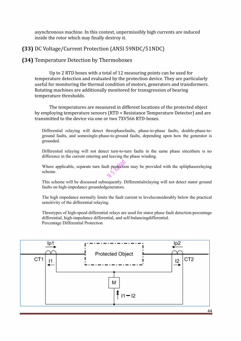
Differential protection systems operate according to the principle of current comparisonand are therefore also known as current balance protection systems. They utilize the fact that in a healthy protected object the current leaving the object is the same as that which entered it (current Ip, dotted in the following figure).
(8) Differential Protection (ANSI 87M/G) for Generators and Motors
Differential protection systems operate according to the principle of current comparison and are therefore also known as current balance protection systems. They utilize the fact that in a healthy protected object the current leaving the object isthe same as that which entered it.
This result shows that for the internal fault under ideal conditions Idiff = Istab.Consequently, the characteristic of internal faults is a straight line with a upward slope of 45° (dot-and-dash line in the following figure).
36

(9) Earth Current Differential Protection (ANSI 87GN,TN)
The earth current differential protection detects earth faults in generators and transformerswith a low-ohmic or solid star point earthing. It is selective, and more sensitive than the classical Differential protection
(10) Under excitation (Loss-of-Field) Protection (ANSI 40)
If The field excitation is lost while the mechanical input remains intact. Since the generator is already synchronized with the grid, it would attempt to remain synchronized by running as an iduction generator. As an induction generator, the machine speeds up slightly above the synchronous speed and draws its excitation from the grid.
On loss of excitation, the terminal voltage begins to decrease and the current begins to increase, resulting in a decrease of impedance and also a change of power factor.
37

(11) Reverse Power Protection (ANSI 32R)
Reverse power protection is used to protect a turbo-generator unit on failure ofenergy to the prime mover when the synchronous generator runs as a motor anddrives the turbine taking motoring energy from the network. This condition leads tooverheating of the turbine blades and must be interrupted within a short time bytripping the network circuit-breaker. For the generator, there is the additional riskthat, in case of a malfunctioning residual steam pass (defective stop valves) after theswitching off of the circuit breakers, the turbine-generator-unit is speeded up, thusreaching an over speed. For this reason, the system isolation should only beperformed after the detection of active power input into the machine.
(12) Forward Active Power Supervision (ANSI 32F)
The machine protection 7UM62 includes an active power supervision which monitors whether the active power falls below one set value as well as whether a
38

separate second set value is exceeded. Each of these functions can initiate different control functions.
(13) Impedance Protection(distance protection) (ANSI 21)
The distance relay applied for this function is intended to isolate thegenerator from the power system for a fault which is not cleared by the transmission line breakers.
Machine impedance protection is used as a selective time graded protection to provide shortest possible tripping times for short-circuits in the synchronous machine, on the terminal leads as well as in the unit transformer. It thus also provides backup protection functions to the main protection of a power plant or protection equipment connected in series like generator, transformer differential and system protection devices.
(14) Out-of-Step Protection (ANSI 78)
Depending on power network conditions and feeding generators, dynamic occurrences such as load jumps, short-circuits not disconnected quickly enough, auto-reclosure or switching actions, may cause system swings. Such power swings endanger power network stability. Stability problems often result from active power swings which can lead to pole-slipping and generator overloading.
The point at which the apparent impedance swing crosses the impedance line between the generator and the system is referred to as the electrical center of the swing and represents the point at which zero voltage occurs when the generator and the system are 180 degrees out-of-phase. During pole slipping the voltage magnitude between the generator and the system reaches two per unit when the angle differencereaches 180 degrees, which can result in high currents that cause mechanical forces in the generator stator windings and undesired transient shaft torques. It is possible for the resulting torques to be of sufficient magnitude to cause the shaft to snap or damage turbine blades.
(15) Under voltage Protection (ANSI 27)
39

Under voltage protection detects voltage dips in electrical machines and avoids inadmissible operating states and possible loss of stability. Two-pole short circuits or earth faults cause asymmetrical voltage collapse. Compared with three single phase measuring systems, the detection of the positive phase-sequence system is not influenced by these procedures and is particularly advantageous for assessing stability problems.
(16) Overvoltage Protection (ANSI 59)
Overvoltage protection serves to protect the electrical machine and connected electrical plant components from the effects of inadmissible voltage increases. Over voltages can be caused by incorrect manual operation of the excitation system, faulty operation of the automatic voltage regulator, (full) load shedding of a generator, separation of the generator from the system or during island operation.
(17) Frequency Protection (ANSI 81)
The frequency protection function detects abnormally high and low frequencies of the generator. If the frequency lies outside the admissible range, appropriate actions are initiated, such as separating the generator from the system.
A decrease in system frequency occurs when the system experiences an increase inreal power demand, or when a frequency or speed control malfunction occurs. The frequency decrease protection is also used for generators which (for a certain time) function on an island network. This is due to the fact that the reverse power protection cannot operate on drive power failure. The generator can be disconnected from the power system using the frequency decrease protection.
An increase in system frequency occurs e.g. when large loads (island network) are removed from the system, or on frequency control malfunction. This entails risk of self excitation for generators feeding long lines under no-load conditions.Through theuse of filters measurement is practically independent of harmonic influencesand veryaccurate.
(18) Over excitation (Volt/Hertz) Protection (ANSI 24)
Over excitation protection is used to detect inadmissibly high induction in generators and transformers, especially in power station unit transformers. The protection must intervene when the limit value for the protected object (e.g. unit transformer) is exceeded. The transformer is endangered, for example, if the power station block is disconnected from the system from full-load, and if the voltage regulator either does not operate or does not operate sufficiently fast to control the associated voltage rise. Similarly a decrease in frequency (speed), e.g. in island systems, can lead to an inadmissible increase in induction.
An increase in induction above the rated value very quickly saturates the iron core and causes large eddy current losses.
40

(19) Inverse-Time Under voltage Protection (ANSI 27)
The inverse under voltage protection mainly protects consumers (induction machines) from the consequences of dangerous voltage drops in island networks avoiding inadmissible operating conditions and possible loss of stability. It can also beused as a criterion for load shedding in interconnected networks. Two-pole short circuits or earth faults cause asymmetrical voltage collapse. Compared with single phase measuring systems, the detection of the positive phase-sequence system is not influenced by these procedures and is therefore especially useful for assessing stability problems.
(20) Rate-of-Frequency-Change Protection df/dt (ANSI 81R)
With the rate-of-frequency-change protection, frequency changes can be quickly detected.This allows a prompt response to frequency dips or frequency rises. A trip command can be issued even before the pickup threshold of the frequency protection (see Section 2.23) is reached.Frequency changes occur for instance when there is an imbalance between the generated and the required active power. They call for control measures on one hand and for switching actions on the other hand. These can be unburdening measures, such as network decoupling, or disconnection of loads (load shedding). The sooner these measures are taken after a malfunction appears, the more effective they are.
The two main applications for this protection function are thus network decoupling and load shedding.
(21) 90-%-Stator Earth Fault Protection (ANSI 59N, 64G, 67G)
The stator earth fault protection detects earth faults in the stator windings of three phase machines. The machine can be operated in busbar connection (directly connected to the network) or in unit connection (via unit transformer). The criterion for the occurrence of an earth fault is mainly the emergence of a displacement voltage, or additionally with busbar connection, of an earth current. This principle makes possible a protected zone of 90 % to 95 % of the stator winding.
(22) Sensitive Earth Fault Protection (ANSI 51GN, 64R)
The highly sensitive earth fault protection detects earth faults in systems with isolated or high-impedance earthed star point. This stage operates with the magnitude of the earth current. It is intended for use where the earth current amplitude gives an indication of the earth fault. As an example of this is with electrical machines in busbar connection in an isolated power system, where during amachine earth fault of the stator winding, the entire network capacity supplies the earth fault current, but with a network earth fault, the earth fault current is negligibledue to the low machine capacitance.
The current may be measured using toroidal CTs.41

(23) 100-%-Stator Earth Fault Protection with 3rd Harmonics (ANSI 27/59TN3rd Harm.)
(24) 100-%-Stator Earth Fault Protection with 20 Hz Voltage Injection (ANSI 64G - 100%)
(25) Sensitive Earth Fault Protection B (ANSI 51GN)
The IEE-B sensitive earth current protection feature of 7UM62 provides greater flexibility and can be used for the following applications.
Applications • Earth current monitoring to detect earth faults (generator stator, terminal lead,ttransformer).• 3rd harmonics earth current measurement for detection of earth faults near the
generatorstar point. The connection is accomplished in the secondary circuit of the neutral transformer.
• Protection against load resistances by means of single-phase current monitoring.• Shaft current protection in order to detect shaft currents of the generator shaft and prevent that bearings take damage. The function is mainly used for hydro-electric generators.
(26) Inter turn Protection (ANSI 59N (IT))
The inter turn fault protection detects faults between turns within a generator winding (phase). This situation may involve relatively high circulating currents that flow in the short-circuited turns and damage the winding and the stator. The potective function is characterized by a high sensitivity.
42

Given the way the generators are constructed, it is rather unlikely that an inter turn fault will occur.
Generators with a separate stator winding (e.g. large-sized hydro-electric generators) are more likely to be affected. In this configuration, the transverse differential protection or the zero sequence current protection are used instead between the connected star points.
(27) Rotor Earth Fault Protection R, fn (ANSI 64R)
Rotor earth fault protection is used to detect earth faults in the excitation circuit of synchronous machines. An earth fault in the rotor winding does not cause immediate damage; however, if a second earth fault occurs it constitutes a winding short-circuit of the excitation circuit. The resulting magnetic imbalances can cause extreme mechanical forces which may destroy the machine.
(28) Sensitive Rotor Earth Fault Protection with 1 to 3 Hz Square Wave Voltage Injection (ANSI 4R - 1 to 3 Hz)
(29) Motor Starting Time Supervision (ANSI 48) (30) Restart Inhibit for Motors (ANSI 66, 49Rotor) (31) Breaker Failure Protection (ANSI 50BF)
In the event of scheduled downtimes or a fault in the generator, the generator can remain on line if the circuit-breaker is defectiveand could suffer substantial damage.
Breaker failure protection evaluates a minimum current and the circuit-breaker auxiliary contact. It can be started by internal protective tripping or externally via binary input. Two-channel activation avoids overfunction.
(32) Inadvertent Energization (ANSI 50, 27)
The inadvertent energizing protection serves to limit damage by accidental connection of the stationary or already started, but not yet synchronized generator, by fast actuation of the mains breaker. A connection to a stationary machine is equivalent to connection to a low-ohmic resistor. Due to the nominal voltage impressed by the power system, the generator starts up with a high slip as an
43
asynchronous machine. In this context, unpermissibly high currents are induced inside the rotor which may finally destroy it.
(33) DC Voltage/Current Protection (ANSI 59NDC/51NDC)
(34) Temperature Detection by Thermoboxes
Up to 2 RTD boxes with a total of 12 measuring points can be used for temperature detection and evaluated by the protection device. They are particularly useful for monitoring the thermal condition of motors, generators and transformers. Rotating machines are additionally monitored for transgression of bearing temperature thresholds.
The temperatures are measured in different locations of the protected object by employing temperature sensors (RTD = Resistance Temperature Detector) and are transmitted to the device via one or two 7XV566 RTD-boxes.
Differential relaying will detect threephasefaults, phase-to-phase faults, double-phase-to-ground faults, and somesingle-phase-to-ground faults, depending upon how the generator isgrounded.
Differential relaying will not detect turn-to-turn faults in the same phase sincethere is nodifference in the current entering and leaving the phase winding.
Where applicable, separate turn fault protection may be provided with the splitphaserelayingscheme.
This scheme will be discussed subsequently. Differentialrelaying will not detect stator groundfaults on high-impedance groundedgenerators.
The high impedance normally limits the fault current to levelsconsiderably below the practicalsensitivity of the differential relaying.
Threetypes of high-speed differential relays are used for stator phase fault detection:percentagedifferential, high-impedance differential, and self-balancingdifferential.Percentage Differential Protection
44

Automatic Field Suppression and use of Neutral Circuit Breaker
In the event of a fault on a generator winding even though the generator circuit breaker is tripped, the fault continues to be fed as long as the excitation will exist because emf is induced in the generator itself.
So it is necessary to discharge excitation magnetic field in the shortest possible interval of time. Hence, it isto be ensured that all the protection system not only trip the alternator circuit breaker but also trip automatic field discharge switch.
The Schematic Diagram for Automatic Field Suppressing and opening of the neutral Circuit Breaker45

In the event of fault the circulating relay contact is closed and so trip coils TC1, TC2, TC3 and TC4 are energized.
The trip coil TC1 opens the main Circuit Breaker while TC2 and TC4 opens the upper contacts, shorts the lower contacts so as to short-circuit the field winding through resistor R1 and R2.
This Process of discharging consists of the isolation of the exciter from the alternator rotor field winding and involves the dissipation of magnetic energy stored in the inductive reactance of the rotor and the main exciter windings.
After the Study of all Protection of 7UM62 Relay we have faced a problem that how we can test that the parameters calculated are correct or not or whether there is any defect that crept in the relay.
Problem associated in 7UM62 Relay:-
I. Burn out of Microprocessor:-
Burn Out is rare case in the 7UM62 Relay. It can happened by ambient temperature rise in surrounding.
II. Mal operation:-
i. Wrong Connection:-
Mal operation occurs due to wrong Connections of Wires with Relay to C.T. & P.T.
ii. Imperfect Time & Peak up Setting:-
Mal operation occurs due to Imperfect time & Peak up setting so relay operate when it’s not required.
III. During testing of one protection function an interfering signal from another function will come and corrupt the test results.
46

Solution:-i. Provide Cooling System:-
To cool down its surrounding temperature we have to installed in Air Conditioner Room.
ii. During testing of one protection function an interfering signal from another function will come and corrupt the test results .
In this case the interfering functions needs to be blocked. i.e. If you conduct Differential Protection on Generator we have to Blocked Earth Fault Differential Protection out of step, Inverse time over current because Earth fault Differential Current Protection, out of step, Inverse time over current will operate fast than Differential Current Transformer.
47

iii. Mal Operation of Relay:-
Mal Operation can be Detected by Testing & Simulation of Relay by testing kit.
Omicron CMC 356The Universal Relay Test Set and Commissioning Tool
Omicron CMC 356 can Detect the Wrong Connection or wrong Time or Wrong Pick up setting in 7UM62 Relay by Simulating ( Creating artificial Faultsin Sytem).
48

The CMC 356 is the universal solution for testing all generations and types of protection relays.Its powerful six current sources (three-phase mode: up to 64 A / 860 VA per channel) with agreat dynamic range, make the unit capable of testing even high-burden electromechanicalrelays with very high power demands. Commissioning engineers will particularly appreciatethe possibility to perform wiring and plausibility checks of current transformers, by using primary injection of high currents from the test set. The CMC 356 is the fi rst choice for applications requiring the highest versatility, amplitude and power.
Application of CMC 365:-
Protection Relay Test Set Power System Simulator Programmable Voltage and
Current Source
Universal Tool for Substation
49

Commissioning
The Siemens 7UM62x test template includes the pick-up and trip time value tests which are performed in a standardized way. For the pick-up value testing, the setting value is evaluated by a ramp increasing the variable under test until the pick-up value is reached.Trip times are tested by simulating a fault which exceeds the pick-up value and the specific tolerances.
This results in a trip command of the tested protection function. The time between the simulation of the fault and the reception of the trip signal is measured and evaluated.
50


