TOSHIBA Portégé M200 Portable Personal Computer User’s Manual UserGuide.pdf · 2011. 2. 27. ·...
252
TOSHIBA Portégé M200 Portable Personal Computer User’s Manual
Transcript of TOSHIBA Portégé M200 Portable Personal Computer User’s Manual UserGuide.pdf · 2011. 2. 27. ·...
TOSHIBA Portégé M200Portable Personal Computer
User’s Manual
Copyright© 2003 by TOSHIBA Corporation. All rights reserved. Under the copyright laws,this manual cannot be reproduced in any form without the prior written permissionof TOSHIBA. No patent liability is assumed, with respect to the use of the informa-tion contained herein.
TOSHIBA Portégé M200 Portable Personal Computer User’s Manual
First edition November 2003
DisclaimerThis manual has been validated and reviewed for accuracy. The instructions anddescriptions it contains are accurate for the TOSHIBA Portégé M200 PortablePersonal Computer at the time of this manual’s production. However, succeedingcomputers and manuals are subject to change without notice. TOSHIBA assumesno liability for damages incurred directly or indirectly from errors, omissions ordiscrepancies between the computer and the manual.
TrademarksIBM is a registered trademark of International Business Machines Corporation.Intel, Pentium and Centrino are registered trademarks and SpeedStep is a trademarkof Intel Corporation.Windows and Microsoft are registered trademarks of Microsoft Corporation.Bluetooth is a trademark owned by its proprietor and used by TOSHIBA underlicence.Other trademarks and registered trademarks not listed above may be used in thismanual.
FCC informationProduct Name : Portégé M200
Model number : PPM20
FCC notice "Declaration of ConformityInformation"This equipment has been tested and found to comply with the limits for a Class Bdigital device, pursuant to part 15 of the FCC rules. These limits are designed toprovide reasonable protection against harmful interference in a residential installa-tion. This equipment generates, uses and can radiate radio frequency energy and, ifnot installed and used in accordance with the instructions, may cause harmfulinterference to radio communications. However, there is no guarantee that interfer-ence will not occur in a particular installation. If this equipment does cause harmfulinterference to radio or television reception, which can be determined by turning theequipment off and on, the user is encouraged to try to correct the interference byone or more of the following measures:
❑ Reorient or relocate the receiving antenna.
❑ Increase the separation between the equipment and receiver.
❑ Connect the equipment into an outlet on a circuit different from that to whichthe receiver is connected.
❑ Consult the dealer or an experienced radio/TV technician for help.
WARNING: Only peripherals complying with the FCC class B limits maybe attached to this equipment. Operation with non-compliant peripher-als or peripherals not recommended by TOSHIBA is likely to result ininterference to radio and TV reception. Shielded cables must be usedbetween the external devices and the computer’s external monitor port,USB port and microphone jack. Changes or modifications made to thisequipment, not expressly approved by TOSHIBA or parties authorized byTOSHIBA could void the user’s authority to operate the equipment. Themodular cable that comes with the computer must be used to connect amodem.

FCC conditionsThis device complies with part 15 of the FCC Rules. Operation is subject to thefollowing two conditions:
1. This device may not cause harmful interference.
2. This device must accept any interference received, including interference thatmay cause undesired operation.
ContactAddress: TOSHIBA America Information Systems, Inc.
9740 Irvine Boulevard
Irvine, California 92618-1697
Telephone: (949) 583-3000
EU Declaration of Conformity
TOSHIBA declares, that the product: PPM20* conforms to the following Standards:
Supplementary Information: “The product complies with the requirements ofthe Low Voltage Directive 73/23/EEC, the EMCDirective 89/336/EEC and/or the R&TTE Directive1999/05/EEC.”
This product is carrying the CE-Mark in accordance with the related EuropeanDirectives. Responsible for CE-Marking is TOSHIBA Europe, Hammfelddamm 8,41460 Neuss, Germany.
VCCI Class B Information

Modem warning noticeConformity StatementThe equipment has been approved to [Commission Decision “CTR21”] for pan-European single terminal connection to the Public Switched Telephone Network(PSTN).
However, due to differences between the individual PSTNs provided in differentcountries/regions the approval does not, of itself, give an unconditional assuranceof successful operation on every PSTN network termination point.
In the event of problems, you should contact your equipment supplier in the firstinstance.
Network Compatibility StatementThis product is designed to work with, and is compatible with the followingnetworks. It has been tested to and found to conform with the additional require-ments conditional in EG 201 121.
Germany ATAAB AN005,AN006,AN007,AN009,AN010 andDE03,04,05,08,09,12,14,17
Greece ATAAB AN005,AN006 and GR01,02,03,04
Portugal ATAAB AN001,005,006,007,011 and P03,04,08,10
Spain ATAAB AN005,007,012, and ES01
Switzerland ATAAB AN002
All other countries/regions ATAAB AN003,004
Specific switch settings or software setup are required for each network, please referto the relevant sections of the user guide for more details.
The hookflash (timed break register recall) function is subject to separate nationaltype approvals. It has not been tested for conformity to national type regulations,and no guarantee of successful operation of that specific function on specificnational networks can be given.
Japan regulations
Region selection
If you are using the computer in Japan, technical regulations described in theTelecommunications Business Law require that you select the Japan region mode. Itis illegal to use the modem in Japan with any other selection.
Redial
Up to two redial attempts can be made. If more than two redial attempts are made,the modem will return Black Listed. If you are experiencing problems with theBlack Listed code, set the interval between redials at one minute or longer.
Japan’s Telecommunications Business Law permits up to two redials on analoguetelephones, but the redials must be made within a total of three minutes.
The internal modem is approved by Japan Approvals Institute for Telecommunica-tions Equipment.
A02-0604JP
Pursuant to FCC CFR 47, Part 68:When you are ready to install or use the modem, call your local telephone companyand give them the following information:
❑ The telephone number of the line to which you will connect the modem
❑ The registration number that is located on the device
The FCC registration number of the modem will be found on either the device whichis to be installed, or, if already installed, on the bottom of the computer outside ofthe main system label.
❑ The Ringer Equivalence Number (REN) of the modem, which can vary. For theREN of your modem, refer to your modem’s label.
The modem connects to the telephone line by means of a standard jack called theUSOC RJ11C.
Type of service
Your modem is designed to be used on standard-device telephone lines. Connec-tion to telephone company-provided coin service (central office implementedsystems) is prohibited. Connection to party lines service is subject to state tariffs. Ifyou have any questions about your telephone line, such as how many pieces ofequipment you can connect to it, the telephone company will provide this informa-tion upon request.
Telephone company procedures
The goal of the telephone company is to provide you with the best service it can. Inorder to do this, it may occasionally be necessary for them to make changes in theirequipment, operations, or procedures. If these changes might affect your service orthe operation of your equipment, the telephone company will give you notice inwriting to allow you to make any changes necessary to maintain uninterruptedservice.
If problems arise
If any of your telephone equipment is not operating properly, you should immedi-ately remove it from your telephone line, as it may cause harm to the telephonenetwork. If the telephone company notes a problem, they may temporarily discon-tinue service. When practical, they will notify you in advance of this disconnection.If advance notice is not feasible, you will be notified as soon as possible. Whenyou are notified, you will be given the opportunity to correct the problem andinformed of your right to file a complaint with the FCC. In the event repairs are everneeded on your modem, they should be performed by TOSHIBA Corporation or anauthorized representative of TOSHIBA Corporation.
Disconnection
If you should ever decide to permanently disconnect your modem from its presentline, please call the telephone company and let them know of this change.

Fax branding
The Telephone Consumer Protection Act of 1991 makes it unlawful for any personto use a computer or other electronic device to send any message via a telephonefax machine unless such message clearly contains in a margin at the top or bottomof each transmitted page or on the first page of the transmission, the date and time itis sent and an identification of the business, other entity or individual sending themessage and the telephone number of the sending machine or such business, otherentity or individual. In order to program this information into your fax modem, youshould complete the setup of your fax software before sending messages.
Instructions for IC CS-03 certified equipment1 The Industry Canada label identifies certified equipment. This certification
means that the equipment meets certain telecommunications network protective,operational and safety requirements as prescribed in the appropriate TerminalEquipment Technical Requirements document(s). The Department does notguarantee the equipment will operate to the user’s satisfaction.
Before installing this equipment, users should ensure that it is permissible to beconnected to the facilities of the local telecommunications company. Theequipment must also be installed using an acceptable method of connection.
The customer should be aware that compliance with the above conditions maynot prevent degradation of service in some situations. Repairs to certifiedequipment should be coordinated by a representative designated by thesupplier. Any repairs or alterations made by the user to this equipment, orequipment malfunctions, may give the telecommunications company cause torequest the user to disconnect the equipment.
Users should ensure for their own protection that the electrical ground connec-tions of the power utility, telephone lines and internal metallic water pipe system,if present, are connected together. This precaution may be particularly importantin rural areas.
CAUTION: Users should not attempt to make such connections them-selves, but should contact the appropriate electric inspection authority,or electrician, as appropriate.
2 The user manual of analog equipment must contain the equipment’s RingerEquivalence Number (REN) and an explanation notice similar to the following:
The Ringer Equivalence Number (REN) of the modem, which can vary. For theREN of your modem, refer to your modem’s label.

NOTICE: The Ringer Equivalence Number (REN) assigned to eachterminal device provides an indication of the maximum number ofterminals allowed to be connected to a telephone interface. The termina-tion on an interface may consist of any combination of devices subjectonly to the requirement that the sum of the Ringer Equivalence Numbersof all the devices does not exceed 5.
3 The standard connecting arrangement (telephone jack type) for this equipment isjack type(s): USOC RJ11C.
The IC registration number of the modem is shown below.
Canada: 1353A-L4AINT
Notes for Users in Australia and New Zealand
Modem warning notice for Australia
Modems connected to the Australian telecoms network must have a valid Austelpermit. This modem has been designed to specifically configure to ensure compli-ance with Austel standards when the country/region selection is set to Australia.The use of other country/region setting while the modem is attached to theAustralian PSTN would result in you modem being operated in a non-compliantmanner. To verify that the country/region is correctly set, enter the command ATIwhich displays the currently active setting.
To set the country/region permanently to Australia, enter the following commandsequence:
AT%TE=1ATS133=1AT&FAT&WAT%TE=0ATZ
Failure to set the modem to the Australia country/region setting as shown abovewill result in the modem being operated in a non-compliant manner. Consequently,there would be no permit in force for this equipment and the Telecoms Act 1991prescribes a penalty of $12,000 for the connection of non-permitted equipment.

Notes for use of this device in New Zealand
❑ The grant of a Telepermit for a device in no way indicates Telecom acceptanceof responsibility for the correct operation of that device under all operatingconditions. In particular the higher speeds at which this modem is capable ofoperating depend on a specific network implementation which is only one ofmany ways of delivering high quality voice telephony to customers. Failure tooperate should not be reported as a fault to Telecom.
❑ In addition to satisfactory line conditions a modem can only work properly if:
a/ it is compatible with the modem at the other end of the call and
b/ the application using the modem is compatible with the application at theother end of the call - e.g., accessing the Internet requires suitablesoftware in addition to a modem.
❑ This equipment shall not be used in any manner which could constitute anuisance to other Telecom customers.
❑ Some parameters required for compliance with Telecom’s PTC Specificationsare dependent on the equipment (PC) associated with this modem. Theassociated equipment shall be set to operate within the following limits forcompliance with Telecom Specifications:
a/ There shall be no more than 10 call attempts to the same number withinany 30 minute period for any single manual call initiation, and
b/ The equipment shall go on-hook for a period of not less than 30 secondsbetween the end of one attempt and the beginning of the next.
c/ Automatic calls to different numbers shall be not less than 5 secondsapart.
❑ Immediately disconnect this equipment should it become physically damaged,and arrange for its disposal or repair.
❑ The correct settings for use with this modem in New Zealand are as follows:
ATB0 (CCITT operation)
AT&G2 (1800 Hz guard tone)
AT&P1 (Decadic dialing make-break ratio =33%/67%)
ATS0=0 (not auto answer)
ATS6=4 (Blind dial deplay)
ATS7=less than 90 (Time to wait to carrier after dialing)
ATS10=less than 150 (loss of carrier to hang up delay, factory default of 15recommended)

ATS11=90 (DTMF dialing on/off duration=90 ms)
ATX2 (Dial tone detect, but not (U.S.A.) call progress detect)
❑ When used in the Auto Answer mode, the S0 register must be set with a valueof 3 or 4. This ensures:
(a) a person calling your modem will hear a short burst of ringing before themodem answers. This confirms that the call has been successfullyswitched through the network.
(b) caller identification information (which occurs between the first andsecond ring cadences) is not destroyed.
❑ The preferred method of dialing is to use DTMF tones (ATDT...) as this isfaster and more reliable than pulse (decadic) dialing. If for some reason youmust use decadic dialing, your communications program must be set up torecord numbers using the following translation table as this modem does notimplement the New Zealand “Reverse Dialing” standard.
Number to be dialed: 0 1 2 3 4 5 6 7 8 9
Number to program into computer: 0 9 8 7 6 5 4 3 2 1
Note that where DTMF dialing is used, the numbers should be enterednormally.
❑ The transmit level from this device is set at a fixed level and because of thisthere may be circumstances where the performance is less than optimal. Beforereporting such occurrences as faults, please check the line with a standardTelepermitted telephone, and only report a fault if the phone performance isimpaired.
❑ It is recommended that this equipment be disconnected from the Telecom lineduring electrical storms.
❑ When relocating the equipment, always disconnect the Telecom line connec-tion before the power connection, and reconnect the power first.
❑ This equipment may not be compatible with Telecom Distinctive Alert ca-dences and services such as Fax Ability.
NOTE THAT FAULT CALLOUTS CAUSED BY ANY OF THE ABOVECAUSES MAY INCUR A CHARGE FROM TELECOM

General conditions
As required by PTC 100, please ensure that this office is advised of any changes tothe specifications of these products which might affect compliance with the relevantPTC Specifications.
The grant of this Telepermit is specific to the above products with the marketingdescription as stated on the Telepermit label artwork. The Telepermit may not beassigned to other parties or other products without Telecom approval.
A Telepermit artwork for each device is included from which you may prepare anynumber of Telepermit labels subject to the general instructions on format, size andcolour on the attached sheet.
The Telepermit label must be displayed on the product at all times as proof topurchasers and service personnel that the product is able to be legitimatelyconnected to the Telecom network.
The Telepermit label may also be shown on the packaging of the product and in thesales literature, as required in PTC 100.
The charge for a Telepermit assessment is $337.50. An additional charge of $337.50is payable where an assessment is based on reports against non-Telecom NewZealand Specifications. $112.50 is charged for each variation when submitted at thesame time as the original.
An invoice for $NZ1237.50 will be sent under separate cover.
xiii
Table of Contents
PrefaceManual contents .................................................................................xixConventions .........................................................................................xxAbbreviations ........................................................................................ xxIcons .................................................................................................... xxKeys .................................................................................................... xxKey operation ...................................................................................... xxiDisplay ................................................................................................ xxiMessages ........................................................................................... xxi
General PrecautionsStress injury ..................................................................................... xxiiiHeat injury ......................................................................................... xxiiiPressure or impact damage ............................................................... xxiiiPC card overheating .......................................................................... xxivMobile phone ..................................................................................... xxivCentral Processing Unit ("CPU") Performance Disclaimer .................. xxivCooling fan ......................................................................................... xxv
Chapter 1 IntroductionEquipment checklist .......................................................................... 1-1Hardware ............................................................................................ 1-1Software ............................................................................................. 1-1
Features ............................................................................................. 1-2Special features................................................................................. 1-6Utilities................................................................................................ 1-9Options ............................................................................................. 1-11
Chapter 2 The Grand TourFront with the display closed ........................................................... 2-1Left side .............................................................................................. 2-2Right side ........................................................................................... 2-3Back side ............................................................................................ 2-4Underside ........................................................................................... 2-5
xiv
Front with the display open .............................................................. 2-7Indicators............................................................................................ 2-9AC adaptor ....................................................................................... 2-12
Chapter 3 Getting StartedSetting up your work space .............................................................. 3-2General conditions .............................................................................. 3-2Placement of computer ....................................................................... 3-3Seating and posture ........................................................................... 3-3Lighting .............................................................................................. 3-4Work habits ........................................................................................ 3-4
Operating the computer in tablet mode .......................................... 3-5Connecting the AC adaptor .............................................................. 3-6Opening the display .......................................................................... 3-8Turning on the power ....................................................................... 3-9Starting up for the first time............................................................ 3-10Turning off the power ..................................................................... 3-10Shut Down mode (Boot mode) .......................................................... 3-10Hibernation mode ............................................................................. 3-11Standby mode .................................................................................. 3-13
Restarting the computer ................................................................. 3-15Restoring the preinstalled software fromthe Product Recovery CD-ROM ....................................................... 3-15
Chapter 4 Operating BasicsUsing the Touch Pad ......................................................................... 4-1Using the Tablet PC Pen and Reserve Pen ..................................... 4-2Inserting the Tablet PC Pen ................................................................ 4-4Removing the Tablet PC Pen .............................................................. 4-5Pen actions ........................................................................................ 4-5Single tap ........................................................................................... 4-5Double tap .......................................................................................... 4-5Press and hold ................................................................................... 4-5Drag ................................................................................................... 4-6Drag and drop ..................................................................................... 4-6Replacing the pen tip .......................................................................... 4-6Inserting the Reserve Pen ................................................................... 4-7Removing the Reserve Pen ................................................................. 4-7
Changing to the Tablet mode........................................................... 4-8Changing the screen orientation ................................................... 4-10
xv
Method 1: Changing the screen orientationusing TOSHIBA Accelerometer Utilities ............................................ 4-11Method 2: Changing the screen orientationusing Cross Function Button ............................................................ 4-12Method 3: Changing the screen orientationusing Task Bar ................................................................................. 4-12
Changing to the laptop mode ......................................................... 4-13Using the USB FDD Kit .................................................................... 4-13Connecting the USB diskette drive ................................................... 4-14Disconnecting the USB diskette drive ............................................... 4-15Diskette care .................................................................................... 4-15
Wireless communications ............................................................... 4-16Wireless LAN ................................................................................... 4-16Bluetooth wireless technology .......................................................... 4-17Wireless communication switch ....................................................... 4-18Wireless communication Indicator .................................................... 4-18
LAN ................................................................................................... 4-19LAN cable types ............................................................................... 4-19Connecting LAN cable ...................................................................... 4-19Disconnecting LAN cable ................................................................. 4-20
Using the microphones ................................................................... 4-21Audio ................................................................................................ 4-21
Using the internal modem .............................................................. 4-24Region selection ............................................................................... 4-25Properties menu ............................................................................... 4-25Connecting ....................................................................................... 4-26Disconnecting ................................................................................... 4-27
Cleaning the computer ................................................................... 4-27Moving the computer ...................................................................... 4-28Heat dispersal .................................................................................. 4-28
Chapter 5 The KeyboardTypewriter keys ................................................................................. 5-1F1 … F12 function keys ..................................................................... 5-2Soft keys: Fn key combinations ........................................................ 5-2Emulating keys on enhanced keyboard .............................................. 5-2Hotkeys .............................................................................................. 5-4Fn Sticky key ..................................................................................... 5-7
Windows special keys ....................................................................... 5-7Keypad overlay .................................................................................. 5-7Turning on the overlays ....................................................................... 5-7
xvi
Temporarily using normal keyboard (overlay on) .................................. 5-8Temporarily using overlay (overlay off) ................................................. 5-9Temporarily changing modes .............................................................. 5-9
Generating ASCII characters ............................................................ 5-9
Chapter 6 Power and Power-Up ModesPower conditions ............................................................................... 6-1Power indicators ............................................................................... 6-3Battery indicators ............................................................................... 6-3DC IN 15V indicator ............................................................................ 6-3Power indicator ................................................................................... 6-4
Battery types ...................................................................................... 6-4Battery Pack ...................................................................................... 6-4Real time clock battery ....................................................................... 6-5
Care and use of the Battery Pack .................................................... 6-5Safety precautions .............................................................................. 6-6Charging the batteries ........................................................................ 6-9Monitoring battery capacity .............................................................. 6-10Maximizing battery operating time .................................................... 6-11Retaining data with power off ............................................................ 6-12Extending battery life ........................................................................ 6-12
Replacing the Battery Pack ............................................................ 6-13Removing the Battery Pack .............................................................. 6-13Installing the Battery Pack................................................................ 6-15
TOSHIBA Password Utility .............................................................. 6-16User password ................................................................................. 6-16Supervisor password ......................................................................... 6-17Starting the computer by password .................................................. 6-18
Tablet mode ..................................................................................... 6-18Power-up modes ............................................................................. 6-19Windows utilities .............................................................................. 6-19Hotkeys ............................................................................................ 6-19
Panel power off ............................................................................... 6-19System Auto Off ............................................................................... 6-20
Chapter 7 HW SetupHW Setup ........................................................................................... 7-1Accessing HW Setup ......................................................................... 7-1HW Setup window .............................................................................. 7-1
xvii
Chapter 8 Optional DevicesPC cards ............................................................................................. 8-2Inserting a PC card ............................................................................. 8-2Removing a PC card ........................................................................... 8-3
SD cards ............................................................................................. 8-3Inserting an SD card ........................................................................... 8-4Removing an SD card ......................................................................... 8-4
Memory expansion ............................................................................ 8-6Installing memory module ................................................................... 8-7Removing memory module.................................................................. 8-9
Battery Pack ..................................................................................... 8-10Universal AC Adaptor ...................................................................... 8-10Battery Charger ............................................................................... 8-11USB diskette Kit ............................................................................... 8-11Tablet Multi Dock ............................................................................. 8-11External monitor .............................................................................. 8-12Tablet PC Pen set ............................................................................ 8-12Reserve pen ..................................................................................... 8-12Security lock .................................................................................... 8-13
Chapter 9 TroubleshootingProblem solving process ................................................................... 9-1Preliminary checklist .......................................................................... 9-1Analyzing the problem ........................................................................ 9-2
Hardware and system checklist ........................................................ 9-3System start-up .................................................................................. 9-3Self test .............................................................................................. 9-4Power ................................................................................................. 9-4Password ........................................................................................... 9-7Keyboard ............................................................................................ 9-8LCD panel .......................................................................................... 9-8Hard disk drive .................................................................................... 9-9Diskette drive ...................................................................................... 9-9Infrared port ...................................................................................... 9-10Pointing device ................................................................................. 9-10PC card ............................................................................................ 9-13SD card ............................................................................................ 9-14Monitor ............................................................................................. 9-14Sound system .................................................................................. 9-15USB ................................................................................................. 9-15Memory expansion ........................................................................... 9-16
xviii
Standby/Hibernation ......................................................................... 9-17Modem ............................................................................................. 9-17LAN .................................................................................................. 9-19Wireless LAN ................................................................................... 9-19Bluetooth .......................................................................................... 9-20Real Time Clock ............................................................................... 9-20
TOSHIBA support ............................................................................. 9-21Before you call ................................................................................. 9-21Where to write .................................................................................. 9-21
AppendixesAppendix ASpecifications .....................................................................................A-1
Appendix BDisplay Controller and Modes ...........................................................B-1
Appendix CAT Commands ....................................................................................C-1
Appendix DS-registers ...........................................................................................D-1
Appendix EV.90 ...................................................................................................... E-1
Appendix FWireless LAN....................................................................................... F-1
Appendix GAC Power Cord and Connectors ....................................................... G-1
Appendix HInternal Modem Guide .......................................................................H-1
Appendix IParts Numbers ..................................................................................... I-1
Glossary
Index
xix
PrefaceCongratulations on your purchase of the TOSHIBA Portégé M200 computer. Thispowerful, lightweight notebook computer is designed to provide years of reliable,high-performance computing.
This manual tells how to set up and begin using your TOSHIBA Portégé M200computer. It also provides detailed information on configuring your computer, basicoperations and care, using optional devices and troubleshooting.
If you are a new user of computers or if you’re new to portable computing, first readover the Introduction and The Grand Tour chapters to familiarize yourself with thecomputer’s features, components and accessory devices. Then read GettingStarted for step-by-step instructions on setting up your computer.
If you are an experienced computer user, please continue reading the preface tolearn how this manual is organized, then become acquainted with this manual bybrowsing through its pages. Be sure to look over the Special features section of theIntroduction, to learn about features that are uncommon or unique to the computersand carefully read HW Setup. If you are going to install PC cards or connect externaldevices such as a monitor, be sure to read Chapter 8, Optional Devices.
Manual contentsThis manual is composed of nine chapters, nine appendixes, a glossary, and anindex.
Chapter 1, Introduction, is an overview of the computer’s features, capabilities, andoptions.
Chapter 2, The Grand Tour, identifies the components of the computer and brieflyexplains how they function.
Chapter 3, Getting Started, provides a quick overview of how to begin operatingyour computer in laptop mode and tablet mode and gives tips on safety anddesigning your work area.
Chapter 4, Operating Basics, includes tips on care of the computer and on using theTouch Pad ,Tablet PC Pen, external diskette drive, Wireless LAN, Bluetooth, LAN,microphone and internal modem.
xx
User's Manual
Chapter 5, The Keyboard, describes special keyboard functions including thekeypad overlay and hotkeys.
Chapter 6, Power and Power-Up Modes, gives details on the computer’s powerresources and battery save modes and how to set a password.
Chapter 7, HW Setup, explains how to configure the computer using the HW Setupprogram.
Chapter 8, Optional Devices, describes the optional hardware available.
Chapter 9, Troubleshooting, provides helpful information on how to perform somediagnostic tests, and suggests courses of action if the computer doesn’t seem to beworking properly.
The Appendixes provide technical information about your computer.
The Glossary defines general computer terminology and includes a list of acronymsused in the text.
The Index quickly directs you to the information contained in this manual.
ConventionsThis manual uses the following formats to describe, identify, and highlight termsand operating procedures.
AbbreviationsOn first appearance, and whenever necessary for clarity, abbreviations are enclosedin parentheses following their definition. For example: Read Only Memory(ROM). Acronyms are also defined in the Glossary.
IconsIcons identify ports, dials, and other parts of your computer. The indicator panelalso uses icons to identify the components it is providing information on.
KeysThe keyboard keys are used in the text to describe many computer operations. Adistinctive typeface identifies the key top symbols as they appear on the keyboard.For example, Enter identifies the Enter key.
xxi
Key operationSome operations require you to simultaneously use two or more keys. We identifysuch operations by the key top symbols separated by a plus sign (+). For example,Ctrl + C means you must hold down Ctrl and at the same time press C. If threekeys are used, hold down the first two and at the same time press the third.
ABC When procedures require an action such as clicking an icon or enteringtext, the icon’s name or the text you are to type in is represented in thetype face you see to the left.
DisplayABC Names of Windows® or icons or text generated by the computer that
appears on its display screen is presented in the type face you see to theleft.
MessagesMessages are used in this manual to bring important information to your attention.Each type of message is identified as shown below.
CAUTION: Pay attention! A caution informs you that improper use ofequipment or failure to follow instructions may cause data loss ordamage your equipment.
NOTE: Please read. A note is a hint or advice that helps you make bestuse of your equipment.
Conventions

xxii
User's Manual

xxiii
General PrecautionsTOSHIBA computers are designed to optimize safety, minimize strain and withstandthe rigors of portability. However, certain precautions should be observed to furtherreduce the risk of personal injury or damage to the computer.
Be certain to read the general precautions below and to note the cautions includedin the text of the manual.
Stress injuryCarefully read the Instruction Manual for Safety & Comfort. It contains informationon prevention of stress injuries to your hands and wrists than can be caused byextensive keyboard use. Chapter 3, Getting Started, also includes information onworkspace design, posture and lighting that can help reduce physical stress.
Heat injury❑ Avoid prolonged physical contact with the computer. If the computer is used
for long periods, its surface can become very warm. While the temperature willnot feel hot to the touch, if you maintain physical contact with the computer fora long time (if you rest the computer on your lap, or if you keep your hands onthe palm rest, for example) your skin might suffer low-heat injury.
❑ If the computer has been used for a long time, avoid direct contact with themetal plate supporting the I/O ports. It can become hot.
❑ The surface of the AC adaptor can become hot when in use. This conditiondoes not indicate a malfunction. If you need to transport the AC adaptor,disconnect it and let it cool before moving it.
❑ Do not lay the AC adaptor on a material that is sensitive to heat. The materialcould be damaged.
Pressure or impact damageDo not apply heavy pressure to the computer or subject it to strong impact.Excessive pressure or impact can cause damage to computer components orotherwise cause malfunctions.
User's Manual
xxiv
PC card overheatingSome PC cards can become hot with prolonged use. Overheating of a PC card canresult in errors or instability in the PC card operation. Also be careful when youremove a PC card that has been used for a long time.
Mobile phoneUse of mobile phones can interfere with the audio system. Computer operation isnot impaired but is recommended that a distance of 30 cm be maintained betweenthe computer and a mobile phone in use.
Central Processing Unit ("CPU") PerformanceDisclaimerCPU Performance in your computer product may vary from specifications under thefollowing conditions:
1. use of certain peripheral products
2. use of battery power instead of AC power
3. use of certain multimedia games or videos with special effects
4. use of standard telephone lines or low speed network connections
5. use of complex modeling software, such as high end computer aided designapplication
6. use of computer in areas with low air pressure (high altitude >1,000 meters or>3,280 feet above sea level)
7. use of computer at temperatures outside the range of 5°C to 35°C (41°F to95°F) or >25°C (77°F) at high altitude (all temperature reference areapproximate).
CPU Performance may also vary from specifications due to design configuration.
Under some conditions, your computer product may automatically shut-down. Thisis a normal protective feature designed to reduce the risk of lost data or damage tothe product when used outside recommended conditions. To avoid risk of lost data,always make back-up copies of data by periodically storing it on an external storagemedium. For optimum performance, use your computer product only underrecommended conditions Read additional restrictions under “EnvironmentalConditions” in your product Resource Guide. Contact TOSHIBA Service andSupport for more information.
xxv
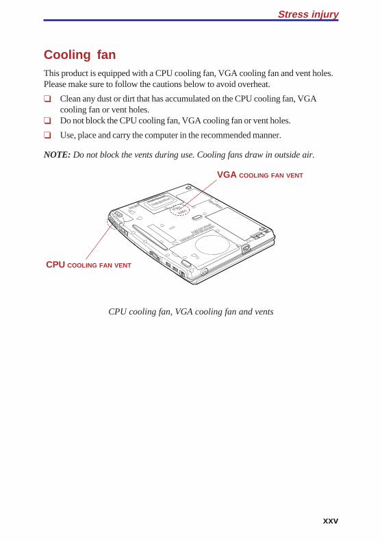
Cooling fanThis product is equipped with a CPU cooling fan, VGA cooling fan and vent holes.Please make sure to follow the cautions below to avoid overheat.
❑ Clean any dust or dirt that has accumulated on the CPU cooling fan, VGAcooling fan or vent holes.
❑ Do not block the CPU cooling fan, VGA cooling fan or vent holes.
❑ Use, place and carry the computer in the recommended manner.
NOTE: Do not block the vents during use. Cooling fans draw in outside air.
CPU cooling fan, VGA cooling fan and vents
Stress injury
CPU COOLING FAN VENT
VGA COOLING FAN VENT

User's Manual
xxvi
INT
RO
DU
CT
ION
Chapter 1
Introduction
Equipment checklist .......................................................................... 1-1Hardware ............................................................................................ 1-1Software ............................................................................................. 1-1
Features ............................................................................................. 1-2Special features................................................................................. 1-6Utilities................................................................................................ 1-9Options ............................................................................................. 1-11

INT
RO
DU
CT
ION
1-1
INT
RO
DU
CT
ION
Chapter 1
IntroductionThis chapter provides an equipment checklist, and it identifies the computer’sfeatures, options and accessories.
CAUTION: Some of the features described in this manual may notfunction properly if you use an operating system that was not prein-stalled by TOSHIBA.
Equipment checklist
Hardware
Carefully unpack your computer. Save the box and packing materials for future use.
Check to make sure you have all the following items:
❑ Portégé M200 Portable Personal Computer
❑ Universal AC adaptor and power cord
❑ Modular cable
❑ Tablet PC Pen
NOTE: Tablet PC Pen is included in the carton of pen set with theproduct when purchased. Spare pen tip and draw-out tool are alsoincluded in the carton.
Software
❑ The following software is preinstalled:
• Microsoft® Windows XP Tablet PC Edition• TOSHIBA Modem driver• TOSHIBA Display driver• TOSHIBA Touch Pad driver• TOSHIBA Sound driver
1-2
User's ManualIN
TR
OD
UC
TIO
N • TOSHIBA Bluetooth drivers (Can be used only in Bluetooth models)• TOSHIBA Wireless LAN Driver• TOSHIBA Mobile Extension3• TOSHIBA Utilities• TOSHIBA Hotkey Utility for Display Devices• TOSHIBA Tablet Access code Logon Utility• TOSHIBA Zooming Utility• TOSHIBA Rotation Utility• TOSHIBA Accelerometer Utilities• TOSHIBA Power Saver• TOSHIBA Common Modules• TOSHIBA Console• TOSHIBA Config Free• TOSHIBA SD Memory Boot Utility• TOSHIBA Skins for Windows Media Player• SD card Driver Set• PC Diagnostic Tool• Online manual• Sensiva Symbol Commander
❑ Documentation:
• Portégé M200 Portable Personal Computer User’s Manual• Microsoft Windows XP Tablet PC Edition manual package• Instruction Manual for Safety & Comfort• End User License Agreement• International Limited Warranty (ILW) Instruction
(This instruction is included only with computers sold in ILW supportedareas.)
❑ Product Recovery CD-ROM (contains TOSHIBA Management Console, whichis not preinstalled)
FeaturesThe computer uses TOSHIBA’s advanced Large Scale Integration (LSI),Complementary Metal-Oxide Semiconductor (CMOS) technology extensively toprovide compact size, minimum weight, low power usage, and high reliability. Thiscomputer incorporates the following features and benefits:
1-3
INT
RO
DU
CT
ION
Processor
Built-in The computer is equipped with an Intel® processor, whichincorporates a math co-processor, a 32 KB level 1 cachememory and a 1MB level 2 cache memory. It also supportsEnhanced Intel® SpeedStep™ technology.
Intel® Pentium® M processor 1.4 GHz
Intel® Pentium® M processor 1.5 GHz
Intel® Pentium® M processor 1.6 GHz
Intel® Pentium® M processor 1.7 GHz
NOTE: Some models of the computers carry Intel® Centrino™technology, which is based on three separate technologies ofIntel® Pentium® M, Intel® PRO/Wireless Network Connection, andIntel® 855 Chipset Family.
Memory
Slot The slot accepts a 128, 256, 512 or 1,024 MB memorymodule can be installed in the two memory slots for amaximum of 2GB system memory.
Level 2 cache 1 MB level 2 cache is provided to maximize performance.
Video RAM 32MB of RAM is provided for Video display.
Disks
Built-in Hard disk
• 40 billion bytes (37.26 GB)
• 60 billion bytes (55.87 GB)
• 80 billion bytes (74.53 GB)
Display
The computer’s LCD panel supports high-resolution video graphics. The screencan be set at a wide range of viewing angles for maximum comfort and readability.
Built-in 12.1" SXGA+-TFT, 1400 horizontal × 1050 vertical pixels,up to 16 M colors.
Graphics controller Graphics controller maximizes display performance. Referto Appendix B for more information.
Features

1-4
User's ManualIN
TR
OD
UC
TIO
N Keyboard
Built-in 84 keys or 85 keys, compatible with IBM ® enhancedkeyboard, embedded numeric overlay, dedicated cursor
control, and keys. See Chapter5, The Keyboard,for details.
Touch pad
Built-in A touch pad and control buttons in the palm rest enablecontrol of the on-screen pointer and scrolling of windows.
Tablet PC Pen
Supplied A pen enables data entry directly through the displayscreen.
Reserve pen
A pen enables data entry directly through the displayscreen. Supplied pen uses a pen instead of Tablet PC Penat the time of loss or breakage.Some computers in the series are equipped with a ReservePen.
Power
Battery pack The computer is powered by one rechargeable lithium-ionbattery pack.
RTC battery The internal RTC battery backs up the Real Time Clock(RTC) and calendar.
AC adaptor The universal AC adaptor provides power to the systemand recharges the batteries when they are low. It comeswith a detachable power cord. Because it is universal, itcan receive a range of AC voltage between 100 and 240volts.
Ports
Headphone Enables connection of a stereo headphone.
Microphone Enables connection of a monaural microphone.
Infrared The serial infrared port is compatible with Infrared DataAssociation (IrDA 1.1) standards. It enables cableless 4Mbps, 1.152 Mbps, 115.2 kbps, 57.6 kbps, 38.4 kbps, 19.2kbps or 9.6 kbps data transfer with IrDA 1.1 compatibleexternal devices.

1-5
INT
RO
DU
CT
ION
External monitor 15-pin, analog VGA port supports VESA DDC2B compat-ible functions.
Docking Special port for connecting an Tablet Multi Dock.
Universal Serial Bus The computer has two Universal Serial Bus ports that(USB 2.0) comply with the USB 2.0 standard, which enables data
transfer speeds 40 times faster than the USB 1.1 standard.(The ports also support USB 1.1.)
Slots
PC card A PC card slot accommodates one 5mm Type II card.
SD card This slot lets you easily transfer data from devices, suchas digital cameras and Personal Digital Assistants, that useSD card flash-memory.You can use memory module in this slot.
Multimedia
Sound System Windows Sound System compatible sound systemprovides internal speaker as well as jacks for an externalmicrophone and headphone.
Communications
Modem An internal modem provides capability for data and faxcommunication. It supports V.90 (V.92). Refer to AppendixE. The speed of data transfer and fax depends on analogtelephone line conditions. It has a modem jack for connect-ing to a telephone line. It is preinstalled as a standarddevice in some markets. Both of V.90 and V.92 aresupported only in USA, Canada and Australia. Only V.90is available in other regions.
LAN The computer is equipped with a LAN card that supportsEthernet LAN (10 Mbit/s, 10BASE-T) and Fast EthernetLAN (100 Mbit/s, 100BASE-TX). It is preinstalled as astandard device in some markets.
Features

1-6
User's ManualIN
TR
OD
UC
TIO
N Wireless LAN Some computers in this series are equipped with a wirelessLAN mini-PCI card that is compatible with other LANsystems based on Direct Sequence Spread Spectrum/Orthogonal Frequency Division Multiplexing radiotechnology that complies with the IEEE802.11 Standard.The configuration of the built-in Wireless LAN dependson the model you purchased.(Revision B or G)Revision G support a data transfer rate up to 54 Mbit/s.Revision B support a data transfer rate up to 11 Mbit/s.
Wireless This switch turns the Wireless LAN and Bluetoothcommunication switch communication switchfunctions on and off.
Bluetooth Some computers in this series are equipped with Bluetoothfunctions. Bluetooth wireless technology eliminates theneed for cables between electronic devices such ascomputers and printers. Bluetooth provides fast, reliable,and secure wireless communication in a small space.
SecuritySecurity lock slot Connects an optional security lock to anchor the computer
to a desk or other large object.
Software
Operating System One of the following operating systems are Windows XPTablet PC Edition. Refer to the Software section at thefront of this chapter.
TOSHIBA Utilities A number of utilities and drivers are preinstalled to makeyour computer more convenient to use. Refer to theUtilities section in this chapter.
Plug and Play When you connect an external device to the computer orwhen you install a component, Plug and Play capabilityenables the system to recognize the connection and makethe necessary configurations automatically.
Special featuresThe following features are either unique to TOSHIBA computers or are advancedfeatures, which make the computer more convenient to use.
1-7
INT
RO
DU
CT
ION
Hot keys Key combinations let you quickly modify the systemconfiguration directly from the keyboard without running asystem configuration program.
Keypad overlay Gray keys with gray lettering make up the keypad overlay,which lets you use the keyboard for ten-key operations orcursor control.
Display automatic This feature automatically cuts off power to the internalpower off display when there is no keyboard input for a time
specified. Power is restored when any key is pressed. Youcan specify the time in the Monitor power off item of theBasic Setup tab in TOSHIBA Power Saver.
HDD automatic This feature automatically cuts off power to the hard diskpower off drive when it is not accessed for a time specified. Power is
restored when the hard disk is accessed. You can specifythe time in the HDD power off item of the Basic Setup tabin TOSHIBA Power Saver.
System automatic This feature automatically shuts down the system inStandby/Hibernation standby mode or Hibernation mode when there is no input
or hardware access for a time specified. You can specifythe time and select either System Standby or SystemHibernate in the System standby and System hibernationitem of the Basic Setup tab in TOSHIBA Power Saver.
Battery save mode This feature lets you save battery power. You can specifythe Power Save Mode in the Profile item in TOSHIBAPower Saver.
Power on password Two levels of password security are available: supervisorand user. This feature prevents unauthorized access toyour computer.
Instant security A hot key function blanks the screen and disables thecomputer providing quick and easy data security.
Intelligent A microprocessor in the computer's intelligent powerpower supply supply detects the battery's charge and calculates the
remaining battery capacity. It also protects electroniccomponents from abnormal conditions, such as voltageoverload from a AC adaptor. You can monitor remainingbattery capacity. Use the Battery remaining item inTOSHIBA Power Saver.
Special features
1-8
User's ManualIN
TR
OD
UC
TIO
N Advanced Instant This function is a utility (one of the acceleration sensorSecurity utilities) with the following functions.
❑ It performs from CrossMenu and PC is changed into aWorkStation lock state.
❑ If PC is moved in the state of a WorkStation lock, beepsound will sound. Cancel a WorkStation lock, in orderto stop beep sound.
❑ If a WorkStation lock is canceled, a program will beended automatically.
Panel power on/off This feature turns power to the computer off when thedisplay panel is closed and turns it back on when the panelis opened. You can specify the setting in the When I closethe lid item of the Setup Action tab in TOSHIBA PowerSaver.
Low battery When battery power is exhausted to the point thatautomatic hibernation computer operation cannot be continued, the system
automatically enters Hibernation and shuts down. You canspecify the setting in the Setup Action tab in TOSHIBAPower Saver.
Auto power on This feature lets you set a time and date for the computerto turn on automatically. The feature is useful for receivingremote communications while you are asleep or away. Youcan specify the setting in Scheduled Tasks.
Standby If you have to interrupt your work, you can turn off thepower without exiting from your software. Data is main-tained in the computer’s main memory. When you turn onthe power again, you can continue working right whereyou left off.
Hibernation This feature lets you turn off the power without exitingfrom your software. The contents of main memory aresaved to the hard disk, when you turn on the power again,you can continue working right where you left off.
Heat dispersal To protect from overheating, the CPU has an internaltemperature sensor. If the computer’s internal temperaturerises to a certain level, the cooling fan is turned on or theprocessing speed is lowered. Use the Cooling Methoditem of the Basic Setup tab in TOSHIBA Power Saver.
Maximum Turns on fan first, then if necessaryPerformance lowers CPU processing speed.
Performance Uses a combination of fan andlowering the CPU processing speed.
1-9
INT
RO
DU
CT
ION
Battery optimized Lowers the CPU processing speedfirst, then if necessary turns on thefan.
UtilitiesThis section describes preinstalled utilities and tells how to start them. For detailson operations, refer to each utility’s online manual, help files or readme.txt files.
TOSHIBA Power Saver To access this power savings management program, openthe Control Panel, click Performance and Maintenance andclick the TOSHIBA Power Saver icon.
HW Setup This program lets you customize your hardware settingsaccording to the way you work with your computer andthe peripherals you use. To start the utility, open theControl Panel, click Printers and Other Hardware and clickthe TOSHIBA HW Setup icon.
Fn-esse This Windows program lets you define your own “short-cut” keys to quickly launch applications and speed yourwork in Windows. To start the utility, click the WindowsStart button, point to All Programs, point to TOSHIBA,point to Utilities and click Fn-esse.
TOSHIBA Password The TOSHIBA Password Utility provides two levels ofUtility password security: User and Supervisor.
Display Driver The display driver enables simultaneous display on the for Windows internal LCD, and on an external computer monitor. To
enable this function, use the Display Properties dialoguebox.
Symbol Commander This software enables the user to run an application or toshow home page by drawing a simple mark on the displaywith the Tablet PC Pen. You can customize the action toboot the computer and to run the application.
TOSHIBA When TOSHIBA Accelerometer Utilities is enabled, youAccelerometer can invoke the Start menu, switch active windows or
Utilities launch predefined applications by shaking the computervertically or horizontally, or tilting it.You can boot TOSHIBA Accelerometer Utilities from themenu bar as follows.[Start]-[All Programs]- [TOSHIBA]-[Tablet PC]-[Setting ofTOSHIBA Accelerometer Utilities]The Setting of TOSHIBA Accelerometer Utilities screenappears.
Utilities
1-10
User's ManualIN
TR
OD
UC
TIO
N Sound drivers A broad range of audio controls are available through theADI sound driver, including Software Synthesize, MicVolume, Noise Resudction and Audio Power Management.
Click Control Panel and click SoundMAX icon to changethe Mic Noise Reduction settings and the Power Manage-ment settings.
For other sound settings, use the Windows DeviceManager, Multimedia Panel or Volume Dial.
TOSHIBA This utility lets you make the Fn key sticky, that is, youAccessibility can press it once, release it, and they press an “F number”
key. The Fn key remains active until another key ispressed.
TOSHIBA Mobile This utility allows you to dock with or undock from aExtension3 docker or port replicator, while your system is powered on,
or while in Stand-by or Hibernation. Settings can bemodified from the "TOSHIBA Mobile Extension3" icon inthe TOSHIBA Console.
Hot key utility This utility lets you display or hide a confirmation messagewhen you press Fn + F3 or Fn + F4.
TOSHIBA Tablet This utility allows you to logon to the system.Access Code If a password has been set, a dialog box with a promptLogon Utility (e.g. Password=) appears when you turn the power on.
If the system is in tablet mode, you can enter a passwordby clicking on keys of the soft keyboard with the TabletPC Pen.
TOSHIBA Zooming This utility allows you to enlarge or reduce the text sizeUtility on the Internet Explorer window and the icon size on
the desktop.
TOSHIBA Console TOSHIBA Console is a graphical user interface thatprovides easy access to help and services. It is the defaultfunction launched by the TOSHIBA Console button.
PC Diagnostic TOSHIBA PC Diagnostic Tool displays the basic inTool formation on PC, and the test of built-in devices can also
be performed.You can boot TOSHIBA PC Diagnostic Toolform the menu bar as follows.
[Start]-[All Programs]-[TOSHIBA]-[Utilities]-[PC Diagnos-tic Tool]
1-11
INT
RO
DU
CT
ION
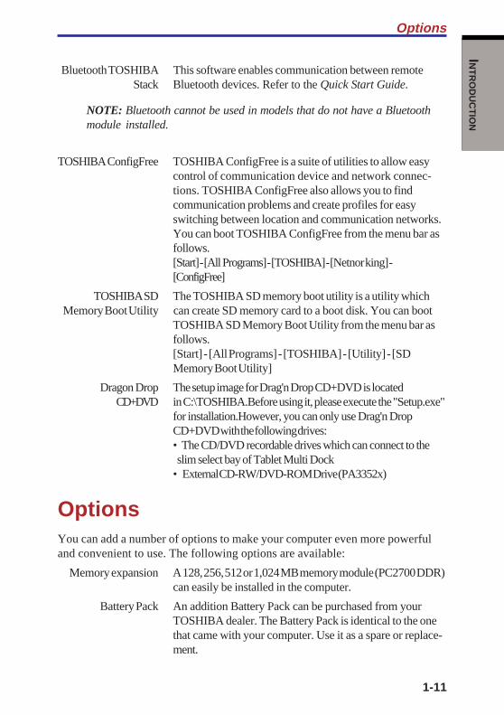
Bluetooth TOSHIBA This software enables communication between remoteStack Bluetooth devices. Refer to the Quick Start Guide.
NOTE: Bluetooth cannot be used in models that do not have a Bluetoothmodule installed.
TOSHIBAConfigFree TOSHIBA ConfigFree is a suite of utilities to allow easycontrol of communication device and network connec-tions. TOSHIBA ConfigFree also allows you to findcommunication problems and create profiles for easyswitching between location and communication networks.You can boot TOSHIBA ConfigFree from the menu bar asfollows.[Start] - [All Programs] - [TOSHIBA] - [Netnor king] -[ConfigFree]
TOSHIBA SD The TOSHIBA SD memory boot utility is a utility whichMemory Boot Utility can create SD memory card to a boot disk. You can boot
TOSHIBA SD Memory Boot Utility from the menu bar asfollows.[Start] - [All Programs] - [TOSHIBA] - [Utility] - [SDMemory Boot Utility]
Dragon Drop The setup image for Drag'n Drop CD+DVD is locatedCD+DVD in C:\TOSHIBA.Before using it, please execute the "Setup.exe"
for installation.However, you can only use Drag'n DropCD+DVD with the following drives:• The CD/DVD recordable drives which can connect to the slim select bay of Tablet Multi Dock• External CD-RW/DVD-ROM Drive (PA3352x)
OptionsYou can add a number of options to make your computer even more powerfuland convenient to use. The following options are available:
Memory expansion A 128, 256, 512 or 1,024 MB memory module (PC2700 DDR)can easily be installed in the computer.
Battery Pack An addition Battery Pack can be purchased from yourTOSHIBA dealer. The Battery Pack is identical to the onethat came with your computer. Use it as a spare or replace-ment.
Options

1-12
User's ManualIN
TR
OD
UC
TIO
N Universal AC Adaptor If you use your computer at more than one site, it may beconvenient to purchase an additional Universal ACAdaptor (PA3282,PA3283) for each site so you will nothave to carry the adaptor with you.
USB FDD Kit A 3 1/2" diskette drive accommodates 1.44-megabyte or720-kilobyte diskettes. It connects to a USB port. (Youcannot format 720-kilobyte diskettes on Windows XP, butyou can use previously formatted disks.)
Battery Charger The Battery Charger lets you charge extra batteries outsidethe computer.
Security locks The slots are available to attach a security cable to thecomputer to deter theft.
Tablet Multi The Tablet Multi Dock provides the ports availableDock on the computer in addition to separate lineout jack,
External monitor port, Universal Serial Bus port × 3, LANjack and Slim Select Bay module.
Wireless LAN Kit This option enables Wireless LAN functions in computerthat does not have preinstalled Wireless LAN. It isinstalled by dealers only.
Bluetooth Kit This option enables Bluetooth wireless communications incomputer that does not have preinstalled Bluetooth. It isinstalled by dealers only.
Tablet PC Pen Tablet PC Pen can be purchased from your TOSHIBAdealer. Use it as a spare to your computer.Spare pen tip and draw-out tool are included.
Reserve pen Reserve Pen can be purchased from your TOSHIBAdealer. Supplied pen uses a pen instead of Supplied pen atthe time of loss or breakage. The pen is set inside thecomputer, which connects a battery pack.
DVD-ROM Drive DVD-ROM Drive is available as an optional externaloptical disk drive. You can buy the drive from TOSHIBAdealer.
External CD-RW/ External CD-RW/DVD-RW is an optional accessoryDVD-RW compatible with USB 2.0 port on this computer. You can
buy the drive from TOSHIBA dealer.
Bluetooth SD card2 Bluetooth SD card is an optional accessory compatiblewith the SD Card slot of this computer. You can buy thecard from TOSHIBA dealer.
TH
E GR
AN
D TO
UR
Chapter 2
The Grand Tour
Front with the display closed ........................................................... 2-1Left side .............................................................................................. 2-2Right side ........................................................................................... 2-3Back side ............................................................................................ 2-4Underside ........................................................................................... 2-5Front with the display open .............................................................. 2-7Indicators ............................................................................................ 2-9AC adaptor ....................................................................................... 2-12

TH
E G
RA
ND T
OU
R

2-1
TH
E GR
AN
D TO
UR
Chapter 2
The Grand TourThis chapter identifies the various components of your computer. Become familiarwith each component before you operate the computer.
Front with the display closedFigure 2-1 shows the computer’s front with its display panel in the closed position.
Figure 2-1 Front of the computer with the display closed
Microphone jack A standard 3.5 mm mini microphone jack enables connec-tion of a monaural microphone or other device for audioinput.
Headphone jack A standard 3.5 mm mini headphone jack enables connec-tion of a stereo headphones (16 ohm minimum) or otherdevice for audio output. When you connect headphones,the internal speaker is automatically disabled.
Volume control Use this dial to adjust the volume of the speaker.
MICROPHONE JACK
HEADPHONE JACK
VOLUME CONTROLDISPLAY LATCH
BUTTONSD CARD SLOT
SD CARD INDICATOR
DOCKNG HOLES

User's Manual
2-2
TH
E G
RA
ND T
OU
R
SD card slot This slot lets you transfer data from the device to yourcomputer.
CAUTION: Keep foreign objects out of the SD card slot. A pin or similarobject can damage the computer’s circuitry.
SD card indicator This indicator glows green when the computer isaccessing the SD card slot.
Display latch The latch mechanism secures the LCD panel in its closedbutton position. Push the Display latch button to release the latch
to open the display.
Docking holes These holes ensure a proper connection between thecomputer and the Tablet Multi Dock.
Left sideFigure 2-2 shows the computer’s left side.
Figure 2-2 The left side of the computer
Security lock A security cable is attached to this slot. The optionalslot security cable anchors your computer to a desk or other
large object to deter theft.
PC card slot A PC card slot can accommodate one 5 mm PC card (TypeII). The slot supports 16-bit PC cards and Card Bus PCcards.
CAUTION: Keep foreign objects out of the PC card slot. A pin or similarobject can damage the computer’s circuitry.
CB
PC CARD SLOTWIRELESS
COMMUNICATION SWITCH
SECURITY LOCK SLOTINFRARED PORT
2-3
TH
E GR
AN
D TO
UR
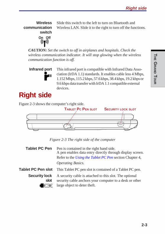
Right side
Wireless Slide this switch to the left to turn on Bluetooth and communication Wireless LAN. Slide it to the right to turn off the functions.
switch
CAUTION: Set the switch to off in airplanes and hospitals. Check thewireless communication indicator. It will stop glowing when the wirelesscommunication function is off.
Infrared port This infrared port is compatible with Infrared Data Asso-ciation (IrDA 1.1) standards. It enables cable less 4 Mbps,1.152 Mbps, 115.2 kbps, 57.6 kbps, 38.4 kbps, 19.2 kbps or9.6 kbps data transfer with IrDA 1.1 compatible externaldevices.
Right sideFigure 2-3 shows the computer’s right side.
Figure 2-3 The right side of the computer
Tablet PC Pen Pen is contained in the right hand side.A pen enables data entry directly through display screen.Refer to the Using the Tablet PC Pen section Chapter 4,
Operating Basics.
Tablet PC Pen slot This Tablet PC pen slot is contained of a Tablet PC pen.
Security lock A security cable is attached to this slot. The optionalslot security cable anchors your computer to a desk or other
large object to deter theft.
On Off
SECURITY LOCK SLOTTABLET PC PEN SLOT
User's Manual
2-4
TH
E G
RA
ND T
OU
R
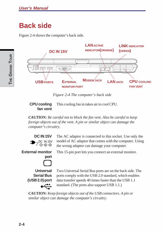
Back sideFigure 2-4 shows the computer’s back side.
Figure 2-4 The computer’s back side
CPU cooling This cooling fan in takes air to cool CPU.fan vent
CAUTION: Be careful not to block the fan vent. Also be careful to keepforeign objects out of the vent. A pin or similar object can damage thecomputer’s circuitry.
DC IN 15V The AC adaptor is connected to this socket. Use only themodel of AC adaptor that comes with the computer. Usingthe wrong adaptor can damage your computer.
External monitor This 15-pin port lets you connect an external monitor.port
Universal Two Universal Serial Bus ports are on the back side. TheSerial Bus ports comply with the USB 2.0 standard, which enables
(USB 2.0) port data transfer speeds 40 times faster than the USB 1.1standard. (The ports also support USB 1.1.)
CAUTION: Keep foreign objects out of the USB connectors. A pin orsimilar object can damage the computer's circuitry.
DC IN 15V
MODEM JACK CPU COOLING
FAN VENT
DC IN 15V
EXTERNAL
MONITOR PORT
LAN ACTIVE
INDICATOR(ORANGE)LINK INDICATOR
(GREEN)
USB PORTS LAN JACK
2-5
TH
E GR
AN
D TO
UR
Underside
LAN jack This jack lets you connect to a LAN. The adaptor hasbuilt-in support for Ethernet LAN (10 megabits per second,10BASE-T) and Fast Ethernet LAN (100 megabits persecond, 100BASE-Tx).
LAN active This indicator glows in orange when data is being indicator (orange) exchanged between the computer and the LAN.
Link indicator This indicator glows in green when the computer is (green) connected to a LAN and the LAN is functioning properly.
Modem jack In areas where an internal modem is installed as standardequipment, there is a modem jack that lets you use amodular cable to connect the modem directly to a tele-phone line. The modem is not supported in some marketingregions.
CAUTIONS: 1. In case of a lightning storm, unplug the modem cablefrom the telephone jack.
2. Do not connect the modem to a digital telephone line.A digital line will damage the modem.
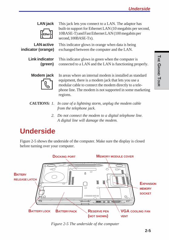
UndersideFigure 2-5 shows the underside of the computer. Make sure the display is closedbefore turning over your computer.
Figure 2-5 The underside of the computer
Ether
BATTERY PACK
MEMORY MODULE COVER
BATTERY LOCK
BATTERY
RELEASE LATCH
RESERVE PEN
(NOT SHOWN)
DOCKING PORT
EXPANSION
MEMORY
SOCKET
VGA COOLING FAN
VENT
User's Manual
2-6
TH
E G
RA
ND T
OU
R
Docking Port Use this port to connect an optional Tablet Multi Dock.
CAUTION: Keep foreign objects out of the docking port. A pin or similarobject can damage the computer’s circuitry.
Expansion The computer is equipped with two expansion memorymemory socket slots (sockets). Use these slots (sockets) to install memory
module to increase your computer’s memory. Refer to theMemory expansion section in Chapter 8, Optional Devicesfor the detail.
Battery Pack The Battery Pack powers the computer when the ACadaptor is not connected. The Battery types section inChapter 6, Power and Power-Up Modes, describes how toaccess the Battery Pack. Battery Packs can be purchasedfrom your TOSHIBA dealer to extend the computer’sbattery operating time.
Battery lock The battery lock prevents inadvertent release of the BatteryPack.
Battery release Releasing the battery lock and sliding the Battery releaselatch latch to the outside of the computer enables to remove the
battery from the computer.
Reserve pen Reserve pen is contained in the battery pack of Underside.Reserve pen enables data entry directly through displayscreen. Refer to the Using the Tablet PC Pen section inChapter4, Operating Basics.
VGA cooling This cooling fan in takes air to cool VGA.fan vent
CAUTION: Be careful not to block the fan vent. Also be careful to keepforeign objects out of the vent.
2-7
TH
E GR
AN
D TO
UR
Front with the display open
Front with the display open
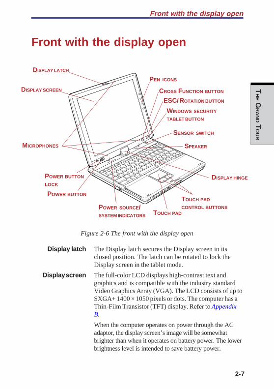
Figure 2-6 The front with the display open
Display latch The Display latch secures the Display screen in itsclosed position. The latch can be rotated to lock theDisplay screen in the tablet mode.
Display screen The full-color LCD displays high-contrast text andgraphics and is compatible with the industry standardVideo Graphics Array (VGA). The LCD consists of up toSXGA+ 1400 × 1050 pixels or dots. The computer has aThin-Film Transistor (TFT) display. Refer to AppendixB.
When the computer operates on power through the ACadaptor, the display screen’s image will be somewhatbrighter than when it operates on battery power. The lowerbrightness level is intended to save battery power.
MICROPHONES
POWER BUTTON
LOCK
POWER BUTTON
SENSOR SWITCH
DISPLAY LATCH
DISPLAY SCREEN
DISPLAY HINGE
TOUCH PAD
TOUCH PAD
CONTROL BUTTONS
SPEAKER
CROSS FUNCTION BUTTON
ESC/ ROTATION BUTTON
WINDOWS SECURITY
TABLET BUTTON
POWER SOURCE/SYSTEM INDICATORS
PEN ICONS

User's Manual
2-8
TH
E G
RA
ND T
OU
R
Display hinge The display hinge holds the display screen at easy-to-viewangles.
Microphones A built-in microphones can be used to record stereosounds into your application.
Power button Slide the power button to turn the computer’s power onand off.
Power button Set this lock to the locked position to prevent inadvertentlock power on or off.
Power source/ LEDs let you monitor the status of various computersystem indicators functions. Details are given in the Indicators section.
Sensor switch This switch shuts down the computer when you close thecover in laptop mode and the panel power on/off feature isenabled. This switch does not shut down the computerwhen operating in tablet mode.
Touch pad A Touch pad located in the center of the palm rest is usedto control the on-screen pointer. Refer to the Using theTouch pad section in Chapter 4, Operating Basics.
Touch pad Control buttons close to the Touch pad let you selectcontrol buttons menu items or manipulate text and graphics designated by
the on-screen pointer.
Windows Security This button functions as the same to Ctrl + Alt + Deltablet button keys to show Windows Task Manager.
Cross Function This button functions as the same to Enter key whenbutton tapped, or shows the menu screen when pressed for
more than a second.
Speaker The speaker emits sound generated by your software aswell as audio alarms, such as low battery condition,generated by the system.
ESC/Rotation Press this button more than one second to change thebutton orientation of the screen. This button also functions as
ESC. When Rotation Utility is running, the top andbottom of the screen are automatically recognized tochange the orientation by pressing this button.
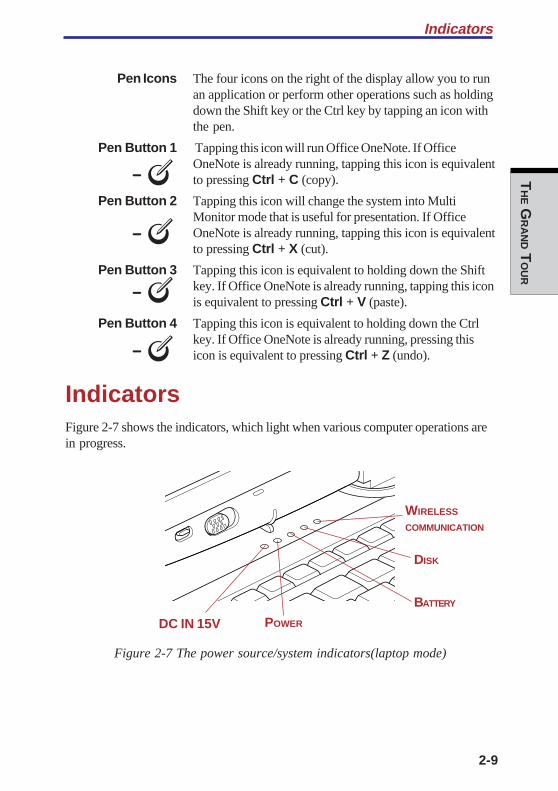
2-9
TH
E GR
AN
D TO
UR
Indicators
Pen Icons The four icons on the right of the display allow you to runan application or perform other operations such as holdingdown the Shift key or the Ctrl key by tapping an icon withthe pen.
Pen Button 1 Tapping this icon will run Office OneNote. If OfficeOneNote is already running, tapping this icon is equivalentto pressing Ctrl + C (copy).
Pen Button 2 Tapping this icon will change the system into MultiMonitor mode that is useful for presentation. If OfficeOneNote is already running, tapping this icon is equivalentto pressing Ctrl + X (cut).
Pen Button 3 Tapping this icon is equivalent to holding down the Shiftkey. If Office OneNote is already running, tapping this iconis equivalent to pressing Ctrl + V (paste).
Pen Button 4 Tapping this icon is equivalent to holding down the Ctrlkey. If Office OneNote is already running, pressing thisicon is equivalent to pressing Ctrl + Z (undo).
IndicatorsFigure 2-7 shows the indicators, which light when various computer operations arein progress.
Figure 2-7 The power source/system indicators(laptop mode)
WIRELESS
COMMUNICATION
DISK
BATTERY
POWERDC IN 15V

User's Manual
2-10
TH
E G
RA
ND T
OU
R
Figure 2-8 The power source/system indicators (tablet mode)
Power source/system indicators
DC IN 15V The DC IN 15V indicator glows green when DC power issupplied from the AC power adaptor. If the adaptor’soutput voltage is abnormal or if the power supply malfunc-tions, this indicator flashes in orange.
Power The Power indicator glows green when the computer ison. If you turn off the computer in Resume mode, thisindicator blinks orange (one second on, two seconds off)while the computer shuts down.
Battery The Battery indicator shows the condition of the charge.Green means fully charged and orange means beingcharged. Refer to Chapter 6, Power and Power-Up Modes.
Disk The Disk indicator glows in green when the computer isaccessing a disk drive.
Wireless The Wireless communication indicator glows when communication the Bluetooth and Wireless LAN functions are turned on.
The figures below show the positions of the keypad overlay indicators and theCapsLock indicator.
When the F10 key indicator glows, the keypad overlay lets you control the cursor.When the F11 key indicator glows, the keypad overlay lets you enter numbers.
WIRELESS
COMMUNICATION
DISKBATTERY
POWER
DC IN 15V

2-11
TH
E GR
AN
D TO
UR
Indicators
Figure 2-9 Keypad overlay indicators
When the CapsLock indicator glows, the keyboard is in all-caps mode.
Figure 2-10 CapsLock indicator
Keyboard indicator
Caps Lock This indicator glows green when the alphabet keys arelocked in uppercase.
Arrow mode When the Arrow mode indicator glows green, you canuse the keypad overlay (white labeled keys) as cursorkeys. Refer to the Keypad overlay section in Chapter 5,The Keyboard.
Numeric mode You can use the keypad overlay (white labeled keys) fornumeric input when the Numeric mode indicator glowsgreen. Refer to the Keypad overlay section in Chapter 5,The Keyboard.
ARROW MODENUMRIC MODE
CAPS LOCK
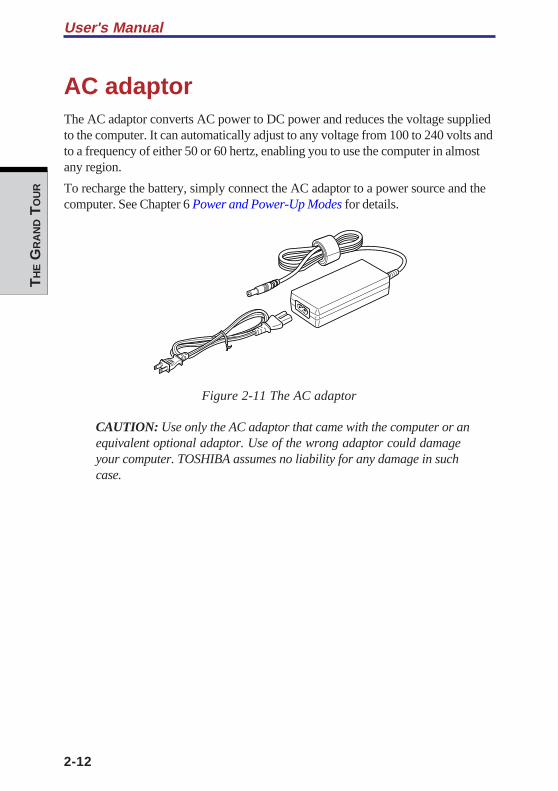
User's Manual
2-12
TH
E G
RA
ND T
OU
R
AC adaptorThe AC adaptor converts AC power to DC power and reduces the voltage suppliedto the computer. It can automatically adjust to any voltage from 100 to 240 volts andto a frequency of either 50 or 60 hertz, enabling you to use the computer in almostany region.
To recharge the battery, simply connect the AC adaptor to a power source and thecomputer. See Chapter 6 Power and Power-Up Modes for details.
Figure 2-11 The AC adaptor
CAUTION: Use only the AC adaptor that came with the computer or anequivalent optional adaptor. Use of the wrong adaptor could damageyour computer. TOSHIBA assumes no liability for any damage in suchcase.

GE
TTING S
TAR
TED
Chapter 3
Getting Started
Setting up your work space .............................................................. 3-2General conditions .............................................................................. 3-2Placement of computer ....................................................................... 3-3Seating and posture ........................................................................... 3-3Lighting .............................................................................................. 3-4Work habits ........................................................................................ 3-4
Operating the computer in tablet mode .......................................... 3-5Connecting the AC adaptor .............................................................. 3-6Opening the display .......................................................................... 3-8Turning on the power ....................................................................... 3-9Starting up for the first time............................................................ 3-10Turning off the power ..................................................................... 3-10Shut Down mode (Boot mode) .......................................................... 3-10Hibernation mode ............................................................................. 3-11Standby mode .................................................................................. 3-13
Restarting the computer ................................................................. 3-15Restoring the preinstalled software fromthe Product Recovery CD-ROM ....................................................... 3-15

GE
TTIN
G S
TAR
TED
GE
TTING S
TAR
TED
3-1
Chapter 3
Getting StartedThis chapter provides basic information to get you started using your computer. Itcovers the following topics:
❑ Setting up your work space — for your health and safety
NOTE: Be sure also to read Instruction Manual for Safety & Comfort. Thisguide, which is included with the computer, explains product liability.
❑ Opening the computer in tablet mode
❑ Connecting the AC adaptor
❑ Opening the display
❑ Turning on the power
❑ Starting up for the first time
❑ Turning off the power
❑ Restarting the computer
❑ Restoring the preinstalled software from the product recovery CD-ROM
NOTE: All users should be sure to carefully read the sections turning onthe power.
3-2
User’s ManualG
ETT
ING S
TAR
TED
Setting up your work spaceEstablishing a comfortable work site is important for you and your computer. Apoor work environment or stressful work habits can result in discomfort or seriousinjury from repetitive strain to your hands, wrists or other joints. Proper ambientconditions should also be maintained for the computer’s operation. This sectiondiscusses the following topics:
❑ General conditions
❑ Placement of the computer and peripheral devices
❑ Seating and posture
❑ Lighting
❑ Work habits
General conditionsIn general, if you are comfortable, so is your computer, but read the following tomake sure your work site provides a proper environment.
❑ Make sure there is adequate space around the computer for proper ventilation.
❑ Make sure the AC power cord connects to an outlet that is close to thecomputer and easily accessible.
❑ The temperature should be 5 to 35 degrees Centigrade (41 to 95 degreesFahrenheit) and the relative humidity should be 20 to 80 percent.
❑ Avoid areas where rapid or extreme changes in temperature or humidity mayoccur.
❑ Keep the computer free of dust, moisture, and exposure to direct sunlight.
❑ Keep the computer away from heat sources, such as electric heaters.
❑ Do not use the computer near liquids or corrosive chemicals.
❑ Do not place the computer near objects that create strong magnetic fields (e.g.,stereo speaker).
❑ Do not operate the computer in close proximity to a mobile phone.
❑ Leave ample ventilation room for the fan. Do not block the vents.
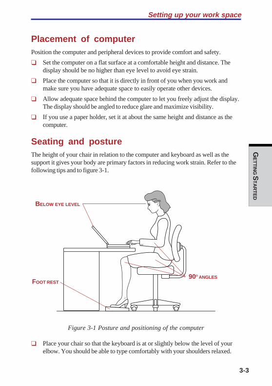
GE
TTING S
TAR
TED
3-3
Setting up your work space
Placement of computerPosition the computer and peripheral devices to provide comfort and safety.
❑ Set the computer on a flat surface at a comfortable height and distance. Thedisplay should be no higher than eye level to avoid eye strain.
❑ Place the computer so that it is directly in front of you when you work andmake sure you have adequate space to easily operate other devices.
❑ Allow adequate space behind the computer to let you freely adjust the display.The display should be angled to reduce glare and maximize visibility.
❑ If you use a paper holder, set it at about the same height and distance as thecomputer.
Seating and postureThe height of your chair in relation to the computer and keyboard as well as thesupport it gives your body are primary factors in reducing work strain. Refer to thefollowing tips and to figure 3-1.
Figure 3-1 Posture and positioning of the computer
❑ Place your chair so that the keyboard is at or slightly below the level of yourelbow. You should be able to type comfortably with your shoulders relaxed.
BELOW EYE LEVEL
90O ANGLESFOOT REST
3-4
User’s ManualG
ETT
ING S
TAR
TED
❑ Your knees should be slightly higher than your hips. If necessary, use a footrest to raise the level of your knees to ease pressure on the back of your thighs.
❑ Adjust the back of your chair so it supports the lower curve of your spine.
❑ Sit straight so that your knees, hips and elbows form approximately 90 degreeangles when you work. Do not slump forward or lean back too far.
LightingProper lighting can improve legibility of the display and reduce eye strain.
❑ Position the computer so that sunlight or bright indoor lighting does not reflectoff the screen. Use tinted windows, shades or other screen to eliminate sunglare.
❑ Avoid placing the computer in front of bright light that could shine directly inyour eyes.
❑ If possible, use soft, indirect lighting in your computer work area. Use a lamp toilluminate your documents or desk, but be sure to position the lamp so that itdoes not reflect off the display or shine in your eyes.
Work habitsA key to avoiding discomfort or injury from repetitive strain is to vary your activi-ties. If possible, schedule a variety of tasks into your work day. If you must spendlong periods at the computer, finding ways to break up the routine can reducestress and improve your efficiency.
❑ Sit in a relaxed posture. Good positioning of your chair and equipment asdescribed earlier can reduce tension in your shoulders or neck and ease backstrain.
❑ Vary your posture frequently.
❑ Occasionally stand up and stretch or exercise briefly.
❑ Exercise and stretch your wrists and hands a number of times during the day.
❑ Frequently, look away from the computer and focus your eyes on a distantobject for several seconds, for example 30 seconds every 15 minutes.
❑ Take frequent short breaks instead of one or two long breaks, for example, twoor three minutes every half hour.
❑ Have your eyes examined regularly and visit a doctor promptly, if you suspectyou might be suffering from a repetitive strain injury.
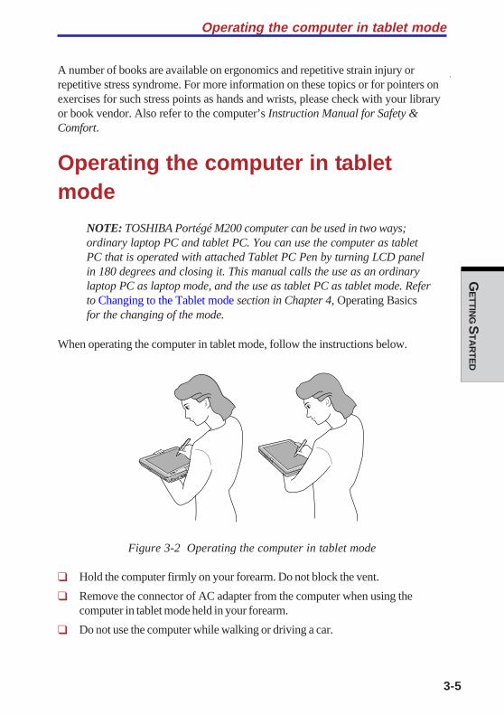
GE
TTING S
TAR
TED
3-5
A number of books are available on ergonomics and repetitive strain injury orrepetitive stress syndrome. For more information on these topics or for pointers onexercises for such stress points as hands and wrists, please check with your libraryor book vendor. Also refer to the computer’s Instruction Manual for Safety &Comfort.
Operating the computer in tabletmode
NOTE: TOSHIBA Portégé M200 computer can be used in two ways;ordinary laptop PC and tablet PC. You can use the computer as tabletPC that is operated with attached Tablet PC Pen by turning LCD panelin 180 degrees and closing it. This manual calls the use as an ordinarylaptop PC as laptop mode, and the use as tablet PC as tablet mode. Referto Changing to the Tablet mode section in Chapter 4, Operating Basicsfor the changing of the mode.
When operating the computer in tablet mode, follow the instructions below.
Figure 3-2 Operating the computer in tablet mode
❑ Hold the computer firmly on your forearm. Do not block the vent.
❑ Remove the connector of AC adapter from the computer when using thecomputer in tablet mode held in your forearm.
❑ Do not use the computer while walking or driving a car.
Operating the computer in tablet mode

3-6
User’s ManualG
ETT
ING S
TAR
TED
❑ Change to laptop mode and turn off the computer before carrying. Do not carrythe computer with power on or in stand by state. Do not carry the computerwhile DISK LED is glowing.
❑ Do not expose the computer with rapid temperature change (such as the caseto bring the PC from cold outside into warm room).When rapid temperature change is unavoidable, turn on the computer after acouple of hours. Avoid dew condensation.
❑ Remove all external peripheral devices and their connection cables from thecomputer before carrying.
❑ Do not drop the computer nor apply excessive impact on the computer. Do notleave the computer in an automobile where the computer is exposed to directsunbeam.
❑ Do not put the computer in tablet mode in a bag.
CAUTION: Do not block the vent of the computer when holding it inyour forearm to use in tablet mode. If you maintain to expose your skin tothe hot air released from the vent for a long time, your skin might sufferlow temperature injury.
Connecting the AC adaptorAttach the AC adaptor when you need to charge the battery or you want to operatefrom AC power. It is also the fastest way to get started, because the Battery Packwill need to be charged before you can operate from battery power.
The AC adaptor can be connected to any power source supplying from 100 to 240volts and 50 or 60 hertz. For details on using the AC adaptor to charge the BatteryPack, refer to Chapter 6, Power and Power-Up Modes.
WARNING: Use only the AC adaptor supplied as an accessory. OtherAC adaptors have different voltage and terminal polarities and use ofthem may produce heat and smoke or even result in fine or rupture.

GE
TTING S
TAR
TED
3-7
Connecting the AC adaptor
CAUTIONS: 1. Use only the AC adaptor supplied with yourcomputer or an equivalent adaptor that iscompatible. Use of any incompatible adaptorcould damage your computer. TOSHIBA assumesno liability for any damage caused by use of anincompatible adaptor.
2. When you connect the AC adaptor tothe computer, always follow the steps in the exactorder as described in the User’s Manual.Connecting the power cable to a live electricaloutlet should be the last step otherwise theadaptor DC output plug could hold an electricalchange and cause an electrical shock or minorbodily injury when touched. As a general safetyprecaution, avoid touching any metal parts.
1. Connect the power cord to the AC adaptor.
Figure 3-3 Connecting the power cord to the AC adaptor

3-8
User’s ManualG
ETT
ING S
TAR
TED
2. Connect the AC adaptor’s DC output plug to the DC IN 15V port on the backof the computer.
Figure 3-4 Connecting the adaptor to the computer
3. Plug the power cord into a live wall outlet. The Battery and DC IN 15Vindicator on the front of the computer should glow.
Opening the displayThe display panel can be rotated in a wide range of angles for optimal viewing.
1. Push down the display latch on the front of the computer to unlatch thedisplay panel.
2. Lift the display panel up and adjust it to the best viewing angle for you.
CAUTION: User reasonable care when opening and closing the displaypanel. Opening it vigorously or slamming it shut could damage thecomputer.
Figure 3-5 Opening the display panel
DC IN 15V PORT
DISPLAY LATCH
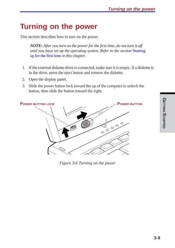
GE
TTING S
TAR
TED
3-9
Turning on the power
Turning on the powerThis section describes how to turn on the power.
NOTE: After you turn on the power for the first time, do not turn it offuntil you have set up the operating system. Refer to the section Startingup for the first time in this chapter.
1. If the external diskette drive is connected, make sure it is empty. If a diskette isin the drive, press the eject button and remove the diskette.
2. Open the display panel.
3. Slide the power button lock toward the up of the computer to unlock thebutton, then slide the button toward the right.
Figure 3-6 Turning on the power
POWER BUTTONPOWER BUTTON LOCK

3-10
User’s ManualG
ETT
ING S
TAR
TED
Starting up for the first timeWhen you first turn on the power, the computer's initial screen is the MicrosoftWindows XP Tablet PC Edition Startup Screen Logo. Follow the on-screendirections for each screen. During setup, you can click the Back button to return tothe previous screen.
Be sure to read the Windows End User License Agreement displaycarefully.
NOTES: 1. You cannot use the Tablet PC Pen when Windows is inSetup. Use keyboard or touch pad while Windows is settingup.
2. Be sure to read the License Agreement carefully.
Turning off the powerThe power can be turned off in one of the following modes: Shut down (Boot),Hibernation or Standby mode.
Shut Down mode (Boot mode)When you turn off the power in Shut Down mode, no data is saved and thecomputer will boot to the operating system’s main screen.
1. If you have entered data, save it to the hard disk or to a diskette.
2. Make sure all disk activity has stopped, then remove any CD/DVD-ROMs ordiskette.
CAUTION: Make sure the Disk indicators is off. If you turn off the powerwhile a disk is being accessed, you can lose data or damage the disk.
3. Click start then click Turn off computer. From the Turn off com-puter menu select, click Turn off .
4. Turn off the power to any peripheral devices.
CAUTION: Do not turn the computer or devices back on immediately.Wait a moment to let all capacitors fully discharge.
GE
TTING S
TAR
TED
3-11
Hibernation modeThe hibernation feature saves the contents of memory to the hard disk when thecomputer is turned off. The next time the computer is turned on, the previous stateis restored. The hibernation feature does not save the status of peripheral devices.
CAUTIONS: 1. Save your data. While entering hibernation mode, thecomputer saves the contents of memory to the HDD.However, for safety sake, it is best to save your datamanually.
2. Data will be lost if you remove the battery or disconnectthe AC adaptor before the save is completed. Wait for theDisk indicator to go out.
3. Do not install or remove a memory module while thecomputer is in hibernation mode. Data will be lost.
Benefits of hibernation
The hibernation feature provides the following benefits:
❑ Saves data to the hard disk when the computer automatically shuts downbecause of a low battery.
NOTE: For the computer to shut down in hibernation mode, the hiberna-tion feature must be enabled in two places : the Hibernate tab in PowerOptions and Setup Action tab in TOSHIBA Power Saver. Otherwise, thecomputer will shut down in Standby mode. If battery power becomesdepleted, data saved in Standby mode will be lost.
❑ You can return to your previous working environment immediately when youturn on the computer.
❑ Saves power by shutting down the system when the computer receives noinput or hardware access for the duration set by the system hibernate feature.
❑ You can use the panel power off feature.
Turning off the power
3-12
User’s ManualG
ETT
ING S
TAR
TED
Starting Hibernation
NOTE: You can also enable Hibernation by pressing Fn + F4. See Chapter5, The Keyboard for details.
To enter Hibernation mode, follow the steps below.
1. Click start.
2. Select Turn Off Computer.
3. Open the Turn Off Computer dialog box. Hibernate is not displayed.
4. Press the Shift key. The Standby item will change to Hibernate.
5. Select Hibernate.
Automatic Hibernation
The computer will enter Hibernate mode automatically when you slide the powerbutton or close the lid. First, however, make the appropriate settings according tothe steps below.
1. Open the Control Panel.
2. Open Performance and Maintenance and open Power Options.
3. Select the Hibernate window in the Power Options Properties,select the Enable hibernation check box and click the Apply button.
4. Open TOSHIBA Power Saver.
5. Select the Setup Action window.
6. Enable the desired Hibernation settings for When I slide the powerbutton and When I close the lid.
7. Click the OK button.
Data save in hibernation mode
When you turn off the power in hibernation mode, the computer takes a moment tosave current memory data to the hard disk. During this time, the Disk indicator willlight.
After you turn off the computer and memory is saved to the hard disk, turn off thepower to any peripheral devices.
CAUTION: Do not turn the computer or devices back on immediately.Wait a moment to let all capacitors fully discharge.
GE
TTING S
TAR
TED
3-13
Turning off the power
Standby modeIf you have to interrupt your work, you can turn off the power without exiting fromyour software. Data is maintained in the computer’s main memory. When you turnon the power again, you can continue working right where you left off.
NOTES: 1. When the AC adaptor is connected, the computer will gointo Standby mode according to the settings in theTOSHIBA Power Saver utility.
2. To restore operation from Standby mode, slide the powerbutton or press any key. The latter action works only ifWake-up on Keyboard is enabled in HW Setup.
3. If the computer automatically enters Standby mode while anetwork application is active, the application might not berestored when the computer wakes up from Standby.
4. To prevent the computer from automatically enteringStandby mode, disable Standby in TOSHIBA Power Saver.That action, however, will nullify the computer’s EnergyStar compliance.
CAUTIONS: 1. Before entering Standby mode, be sure to save yourdata.
2. Do not install or remove a memory module while thecomputer is in standby mode. The computer or the
module could be damaged.
3. Do not remove the battery pack while the computer is instandby mode (unless the computer is connected to anAC power source). Data in memory will be lost.
4. If you carry the computer on board an aircraft or into ahospital, be sure to shut down the computer inhibernation mode or in shutdown mode to avoid radiosignal interference.
3-14
User’s ManualG
ETT
ING S
TAR
TED
Benefits of standby
The standby feature provides the following benefits:
❑ Restores the previous working environment more rapidly than does hiberna-tion.
❑ Saves power by shutting down the system when the computer receives noinput or hardware access for the duration set by the System Standby feature.
❑ You can use the panel power off feature.
Executing standby
NOTE: You can also enable Standby by pressing Fn + F3. See Chapter 5,The Keyboard, for details.
You can enter standby mode in one of three ways:
1. Click Start, click Turn Off Computer and click Stand by.
2. Close the display panel. This feature must be enabled. Refer to the SetupAction tab in TOSHIBA Power Saver Utility described in the ControlPanel.
Open Performance and Maintenance and open TOSHIBA PowerSaver.
3. Slide the power button. This feature must be enabled. Refer to the SetupAction tab in TOSHIBA Power Saver Utility described in the ControlPanel.
When you turn the power back on, you can continue from where you left when youshut down the computer.
NOTES: 1. When the computer is shut down in standby mode, thepower indicator flashes in orange.
2. If you are operating the computer on battery power, youcan lengthen the operating time by shutting down inhibernation mode. Standby mode consumes more power.
GE
TTING S
TAR
TED
3-15
Restarting the computer
Standby limitations
Standby will not function under the following conditions:
❑ Power is turned back on immediately after shutting down.
❑ Memory circuits are exposed to static electricity or electrical noise.
Restarting the computerCertain conditions require that you reset the system. For example, if:
❑ You change certain computer settings.
❑ An error occurs and the computer does not respond to your keyboardcommands.
There are three ways to restart the computer system:
1. Press Ctrl + Alt + Del or Windows Security tablet button to display theWindows Task Manager, then select Shutdown and Restart.
2. Select Restart from the Turn Off Computer window in the start menu.
3. Slide the power button and hold it down for five seconds. Wait 10 to 15seconds, then turn the power on again by sliding the power button.
Restoring the preinstalled softwarefrom the Product Recovery CD-ROMIf preinstalled files are damaged, use the Product Recovery CD-ROM to restorethem. To restore the operating system and all preinstalled software, follow the stepsbelow.
CAUTION: When you reinstall the Windows operating system, the harddisk will be reformatted and all data will be lost.
1. Load the Product Recovery CD-ROM in the external optional optical disk driveand turn off the computer’s power.
2. Hold down the F12 key and turn on the power. When In Touch withTomorrow TOSHIBA appears, release the F12 key.
3. Use the left or right cursor key to select the CD-ROM icon in the displaymenu. For details, refer to the Boot priority section in Chapter 7, HW Setup.
4. Follow the on-screen instructions.

3-16
User’s ManualG
ETT
ING S
TAR
TED
OP
ER
AT
ING B
AS
ICS
Chapter 4
Operating Basics
Using the Touch Pad ......................................................................... 4-1Using the Tablet PC Pen and Reserve Pen ..................................... 4-2Inserting the Tablet PC Pen ................................................................ 4-4Removing the Tablet PC Pen .............................................................. 4-5Pen actions ........................................................................................ 4-5Single tap ........................................................................................... 4-5Double tap .......................................................................................... 4-5Press and hold ................................................................................... 4-5Drag ................................................................................................... 4-6Drag and drop ..................................................................................... 4-6Replacing the pen tip .......................................................................... 4-6Inserting the Reserve Pen ................................................................... 4-7Removing the Reserve Pen ................................................................. 4-7
Changing to the Tablet mode ........................................................... 4-8Changing the screen orientation ................................................... 4-10Method 1: Changing the screen orientationusing TOSHIBA Accelerometer Utilities ............................................ 4-11Method 2: Changing the screen orientationusing Cross Function Button ............................................................ 4-12Method 3: Changing the screen orientationusing Task Bar ................................................................................. 4-12
Changing to the laptop mode ......................................................... 4-13Using the USB FDD Kit .................................................................... 4-13Connecting the USB diskette drive ................................................... 4-14Disconnecting the USB diskette drive ............................................... 4-15Diskette care .................................................................................... 4-15
Wireless communications ............................................................... 4-16Wireless LAN ................................................................................... 4-16Bluetooth wireless technology .......................................................... 4-17Wireless communication switch ....................................................... 4-18Wireless communication Indicator .................................................... 4-18
LAN ................................................................................................... 4-19LAN cable types ............................................................................... 4-19Connecting LAN cable ...................................................................... 4-19Disconnecting LAN cable ................................................................. 4-20
OP
ER
AT
ING B
AS
ICS
Using the microphones ................................................................... 4-21Audio ................................................................................................ 4-21
Using the internal modem .............................................................. 4-24Region selection ............................................................................... 4-25Properties menu ............................................................................... 4-25Connecting ....................................................................................... 4-26Disconnecting ................................................................................... 4-27
Cleaning the computer ................................................................... 4-27Moving the computer ...................................................................... 4-28Heat dispersal .................................................................................. 4-28
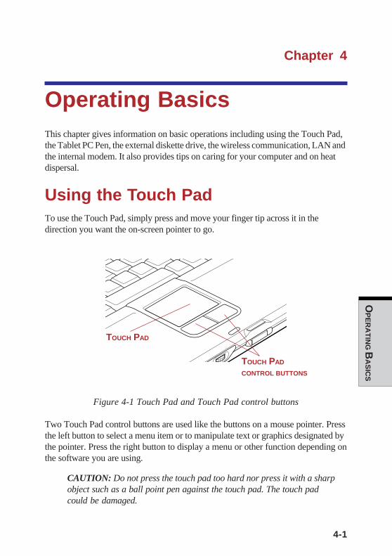
4-1
OP
ER
AT
ING B
AS
ICS
Chapter 4
Operating BasicsThis chapter gives information on basic operations including using the Touch Pad,the Tablet PC Pen, the external diskette drive, the wireless communication, LAN andthe internal modem. It also provides tips on caring for your computer and on heatdispersal.
Using the Touch PadTo use the Touch Pad, simply press and move your finger tip across it in thedirection you want the on-screen pointer to go.
Figure 4-1 Touch Pad and Touch Pad control buttons
Two Touch Pad control buttons are used like the buttons on a mouse pointer. Pressthe left button to select a menu item or to manipulate text or graphics designated bythe pointer. Press the right button to display a menu or other function depending onthe software you are using.
CAUTION: Do not press the touch pad too hard nor press it with a sharpobject such as a ball point pen against the touch pad. The touch padcould be damaged.
TOUCH PAD
TOUCH PAD
CONTROL BUTTONS
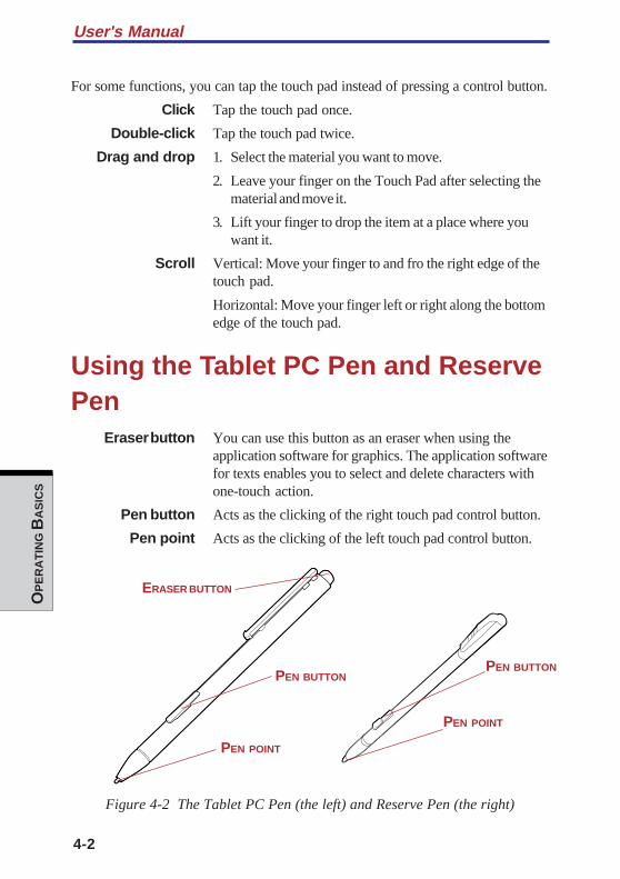
User's Manual
4-2
OP
ER
AT
ING B
AS
ICS
For some functions, you can tap the touch pad instead of pressing a control button.
Click Tap the touch pad once.
Double-click Tap the touch pad twice.
Drag and drop 1. Select the material you want to move.
2. Leave your finger on the Touch Pad after selecting thematerial and move it.
3. Lift your finger to drop the item at a place where youwant it.
Scroll Vertical: Move your finger to and fro the right edge of thetouch pad.
Horizontal: Move your finger left or right along the bottomedge of the touch pad.
Using the Tablet PC Pen and ReservePen
Eraser button You can use this button as an eraser when using theapplication software for graphics. The application softwarefor texts enables you to select and delete characters withone-touch action.
Pen button Acts as the clicking of the right touch pad control button.
Pen point Acts as the clicking of the left touch pad control button.
Figure 4-2 The Tablet PC Pen (the left) and Reserve Pen (the right)
ERASER BUTTON
PEN BUTTON
PEN POINT
PEN BUTTON
PEN POINT

4-3
OP
ER
AT
ING B
AS
ICS
You can use the Tablet PC Pen to execute actions and enter data. Hold the TabletPC Pen in a natural position and tap, press or trace on the screen lightly. Before youbegin using the TOSHIBA Portégé M200 for the first time, you will need to calibratethe Tablet PC Pen. Refer to the Pointing device section in Chapter9, Troubleshooting.Some computers in the series are equipped with a Reserve Pen.
CAUTIONS: Observe the following precautions on the handling of theTablet PC Pen.
1. Do not tap or press the Tablet PC Pen forcefully againstthe Display screen. It could damage the Tablet PC Penand Display screen.
2. Avoid using or keeping the Tablet PC Pen in the placeof rapid temperature change or in a car where theTablet PC Pen is exposed to direct sunbeam.Keep the Tablet PC Pen without pressure constantlyapplied to the switch of the Tablet PC Pen. Constantpressure to the button causes a malfunction or charac-teristic deterioration.
3. The Tablet PC Pen is composed of precision parts. Donot drop the Tablet PC Pen. Strong impact causes amalfunction or characteristic deterioration.
4. Do not apply excessive force to the Tablet PC Pen pointand the side switch. Excessive force applied to theseparts causes short life or characteristic deterioration.(Allowable force to pen point, Eraser button, Penbutton: less than 1 kg, for less than 30 seconds)
5. Avoid water to enter in the Tablet PC Pen or dewcondensation. Intrusion of water or dew condensationcauses malfunction.
6. Do not disassemble the Tablet PC Pen. It causesmaladjustment or short life.
7. Do not stain the Tablet PC Pen with cosmetics orchemicals. It causes deterioration of appearance.Use a glass wiping cloth or dry cloth to clean the TabletPC Pen when cleaning. Do not use volatile liquid suchas alcohol, thinner or petroleum benzine.
Using the Tablet PC Pen and Reserve Pen
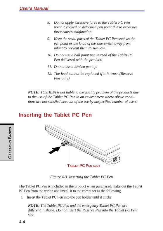
User's Manual
4-4
OP
ER
AT
ING B
AS
ICS
8. Do not apply excessive force to the Tablet PC Penpoint. Crooked or deformed pen point due to excessiveforce causes malfunction.
9. Keep the small parts of the Tablet PC Pen such as thepen point or the knob of the side switch away frominfant to prevent them to swallow.
10. Do not use a ball point pen instead of the Tablet PCPen delivered with the product.
11. Do not use a broken pen tip.
12. The lead cannot be replaced if it is worn.(ReservePen only)
NOTE: TOSHIBA is not liable to the quality problem of the products dueto the use of the Tablet PC Pen in an environment where above condi-tions are not satisfied because of the use by unspecified number of users.
Inserting the Tablet PC Pen
Figure 4-3 Inserting the Tablet PC Pen
The Tablet PC Pen is included in the product when purchased. Take out the TabletPC Pen from the carton and install it to the computer as the following.
1. Insert the Tablet PC Pen into the pen holder until it clicks.
NOTE: The Tablet PC Pen and the emergency Tablet PC Pen aredifferent in shape. Do not insert the Reserve Pen into the Tablet PC Penslot.
TABLET PC PEN SLOT
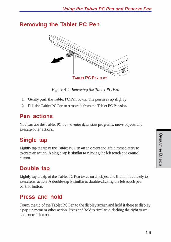
4-5
OP
ER
AT
ING B
AS
ICS
Using the Tablet PC Pen and Reserve Pen
Removing the Tablet PC Pen
Figure 4-4 Removing the Tablet PC Pen
1. Gently push the Tablet PC Pen down. The pen rises up slightly.
2. Pull the Tablet PC Pen to remove it from the Tablet PC Pen slot.
Pen actionsYou can use the Tablet PC Pen to enter data, start programs, move objects andexecute other actions.
Single tapLightly tap the tip of the Tablet PC Pen on an object and lift it immediately toexecute an action. A single tap is similar to clicking the left touch pad controlbutton.
Double tapLightly tap the tip of the Tablet PC Pen twice on an object and lift it immediately toexecute an action. A double-tap is similar to double-clicking the left touch padcontrol button.
Press and holdTouch the tip of the Tablet PC Pen to the display screen and hold it there to displaya pop-up menu or other action. Press and hold is similar to clicking the right touchpad control button.
TABLET PC PEN SLOT
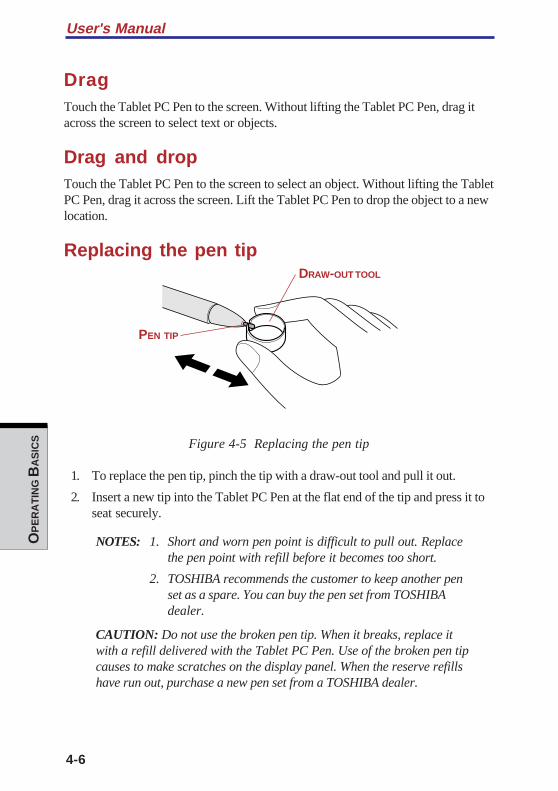
User's Manual
4-6
OP
ER
AT
ING B
AS
ICS
DragTouch the Tablet PC Pen to the screen. Without lifting the Tablet PC Pen, drag itacross the screen to select text or objects.
Drag and dropTouch the Tablet PC Pen to the screen to select an object. Without lifting the TabletPC Pen, drag it across the screen. Lift the Tablet PC Pen to drop the object to a newlocation.
Replacing the pen tip
Figure 4-5 Replacing the pen tip
1. To replace the pen tip, pinch the tip with a draw-out tool and pull it out.
2. Insert a new tip into the Tablet PC Pen at the flat end of the tip and press it toseat securely.
NOTES: 1. Short and worn pen point is difficult to pull out. Replacethe pen point with refill before it becomes too short.
2. TOSHIBA recommends the customer to keep another penset as a spare. You can buy the pen set from TOSHIBAdealer.
CAUTION: Do not use the broken pen tip. When it breaks, replace itwith a refill delivered with the Tablet PC Pen. Use of the broken pen tipcauses to make scratches on the display panel. When the reserve refillshave run out, purchase a new pen set from a TOSHIBA dealer.
DRAW-OUT TOOL
PEN TIP
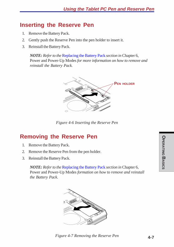
4-7
OP
ER
AT
ING B
AS
ICS
Using the Tablet PC Pen and Reserve Pen
Inserting the Reserve Pen1. Remove the Battery Pack.
2. Gently push the Reserve Pen into the pen holder to insert it.
3. Reinstall the Battery Pack.
NOTE: Refer to the Replacing the Battery Pack section in Chapter 6,Power and Power-Up Modes for more information on how to remove andreinstall the Battery Pack.
Figure 4-6 Inserting the Reserve Pen
Removing the Reserve Pen1. Remove the Battery Pack.
2. Remove the Reserve Pen from the pen holder.
3. Reinstall the Battery Pack.
NOTE: Refer to the Replacing the Battery Pack section in Chapter 6,Power and Power-Up Modes formation on how to remove and reinstallthe Battery Pack.
Figure 4-7 Removing the Reserve Pen
PEN HOLDER

User's Manual
4-8
OP
ER
AT
ING B
AS
ICS
Changing to the Tablet modeTo change the laptop mode to the tablet mode, follow the instructions below.
Figure 4-8 Changing to the Tablet mode (1)
CAUTION: Place the computer on a stable, flat place such as a desktopand rotate the display panel slowly, holding the panel at its lower part.The display panel is designed not to rotate more than 180 degrees.Rotating the display panel more than 180 degrees with an excessiveforce causes to damage the panel.
The rotating direction to change the mode is the following:
From laptop mode to Tablet mode: clockwise 180 degrees
Tablet Turn the display panel to the direction indicated by themode icon Tablet mode icon .
From Tablet mode to laptop mode: counter-clockwise 180 degrees
Laptop mode icon Turn the display panel to the direction indicated bythe laptop mode icon.
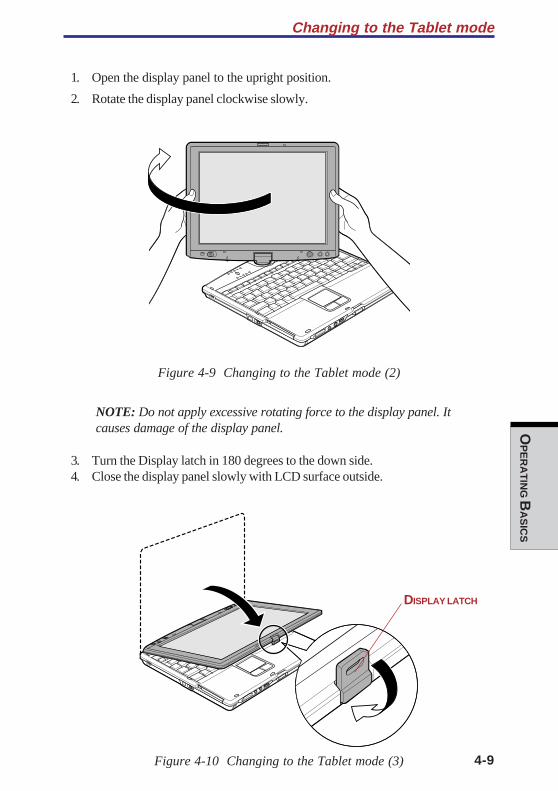
4-9
OP
ER
AT
ING B
AS
ICS
Changing to the Tablet mode
1. Open the display panel to the upright position.
2. Rotate the display panel clockwise slowly.
Figure 4-9 Changing to the Tablet mode (2)
NOTE: Do not apply excessive rotating force to the display panel. Itcauses damage of the display panel.
3. Turn the Display latch in 180 degrees to the down side.4. Close the display panel slowly with LCD surface outside.
Figure 4-10 Changing to the Tablet mode (3)
DISPLAY LATCH

User's Manual
4-10
OP
ER
AT
ING B
AS
ICS
5. Turn the Display latch downward.
6. Insert the Display latch in the slit.
7. Press the display panel downward softly.
Figure 4-11 Changing to the Tablet mode (4)
Changing the screen orientationThe orientation of desktop screen can be changed to one of the following fourdisplay modes:
DISPLAY LATCH
SLIT
Primary landscape Secondary landscape
Primary portrait Secondary portrait

4-11
OP
ER
AT
ING B
AS
ICS
Changing the screen orientation
NOTES:1. Execute the following applications on Primary landscape:
• 3D game software• 3D screen saver• Playback of motion picture, such as a case of DVD-Video playback
on the computer connecting an external DVD-ROM Drive.
CAUTION: Do not play 3D game software or replay DVD-Video on thescreen other than Primary landscape. An abnormality will appear on theWindows screen display when you replay a DVD-Video on the screenother than Primary landscape because DVD playback software can bootonly in the Primary landscape.
2. The screen cannot rotate in one of the following cases. Quit therunning application and then rotate the screen:
• Running of the application that changes the screen resolutiondynamically (such as a game that is execute on full-screen mode)
• DOS prompt in full-screen mode• Running of 3D screen saver
CAUTION: An abnormality will appear a part of the Windows screendisplay when you change the PC from Tablet mode to laptop mode while3D screen saver is running. In such a case, press any key in the laptopmode to cancel 3D screen saver.
Method 1: Changing the screen orientationusing TOSHIBA Accelerometer UtilitiesWhen TOSHIBA Accelerometer Utilities is enabled, you can invoke the Start menu,switch active windows or launch predefined applications by shaking the computervertically or horizontally, or tilting it.
CAUTION: When you shake the computer:
❑ Do not shake the computer too strongly.
If so, the computer may drop from your hands or hit persons or things around.
❑ Avoid using the computer in crowded places. (e.g. in commuter trains or inbusy streets)
This may cause injury to a child or adult, and damage to the computer.
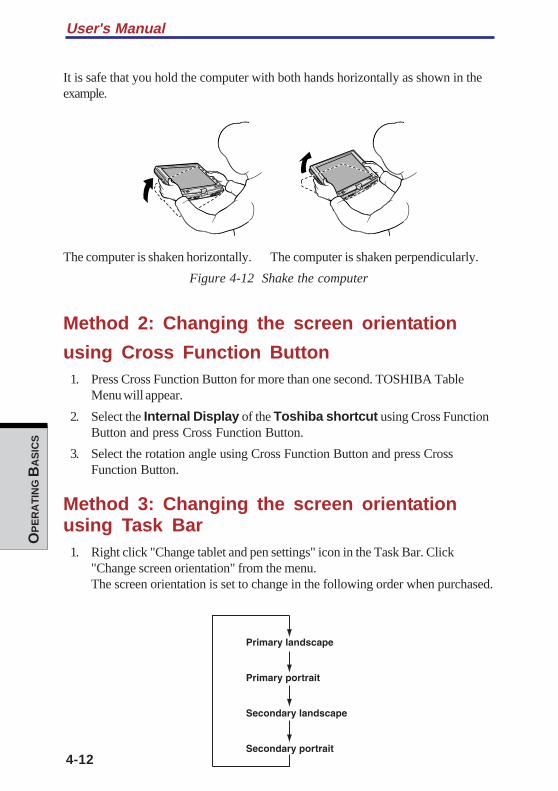
User's Manual
4-12
OP
ER
AT
ING B
AS
ICS
It is safe that you hold the computer with both hands horizontally as shown in theexample.
The computer is shaken horizontally. The computer is shaken perpendicularly.
Figure 4-12 Shake the computer
Method 2: Changing the screen orientation
using Cross Function Button1. Press Cross Function Button for more than one second. TOSHIBA Table
Menu will appear.
2. Select the Internal Display of the Toshiba shortcut using Cross FunctionButton and press Cross Function Button.
3. Select the rotation angle using Cross Function Button and press CrossFunction Button.
Method 3: Changing the screen orientationusing Task Bar
1. Right click "Change tablet and pen settings" icon in the Task Bar. Click"Change screen orientation" from the menu.The screen orientation is set to change in the following order when purchased.
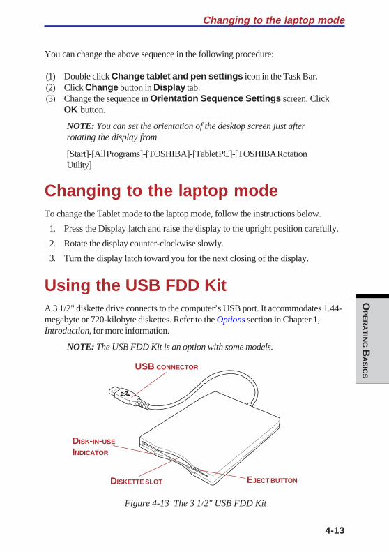
4-13
OP
ER
AT
ING B
AS
ICS
Changing to the laptop mode
You can change the above sequence in the following procedure:
(1) Double click Change tablet and pen settings icon in the Task Bar.(2) Click Change button in Display tab.(3) Change the sequence in Orientation Sequence Settings screen. Click
OK button.
NOTE: You can set the orientation of the desktop screen just afterrotating the display from
[Start]-[All Programs]-[TOSHIBA]-[Tablet PC]-[TOSHIBA RotationUtility]
Changing to the laptop modeTo change the Tablet mode to the laptop mode, follow the instructions below.
1. Press the Display latch and raise the display to the upright position carefully.
2. Rotate the display counter-clockwise slowly.
3. Turn the display latch toward you for the next closing of the display.
Using the USB FDD KitA 3 1/2" diskette drive connects to the computer’s USB port. It accommodates 1.44-megabyte or 720-kilobyte diskettes. Refer to the Options section in Chapter 1,Introduction, for more information.
NOTE: The USB FDD Kit is an option with some models.
Figure 4-13 The 3 1/2" USB FDD Kit
DISK-IN-USE
INDICATOR
DISKETTE SLOT EJECT BUTTON
USB CONNECTOR

User's Manual
4-14
OP
ER
AT
ING B
AS
ICS
Eject button When a diskette is fully seated in the drive, the ejectbutton pops out. To remove a diskette, push in the ejectbutton and the diskette pops out partially for easy removal.
Diskette slot Insert diskettes in this slot.
Disk-In-Use This indicator lights when the diskette is beingIndicator accessed.
CAUTION: Check the Disk-In-Use indicator when you use the diskettedrive. Do not press the eject button, disconnect a drive cable or turn offthe computer while the light is glowing. Doing so could destroy data anddamage the diskette or the drive.
NOTES: 1. The external diskette drive should be placed on a flat,horizontal surface when in use. Do not set the drive on anincline greater than 20o while it is operating.
2. Do not set anything on top of the diskette drive.
3. If you need to boot the computer from the diskette drive orif you use an OS that does not support USB, you must setthe USB-FDD Legacy Emulation feature in HW Setup toEnabled. Refer to the USB section in Chapter 7, HW SetUP.
Connecting the USB diskette driveTo connect the drive, plug the diskette drive connector into a USB port. Refer toFigure 4-13.
NOTE: Make sure the connector is right side up and properly alignedwith the socket. Do not try to force the connection, doing so can damagethe connecting pins.
Figure 4-14 Connecting the diskette drive to the computer
USB CONNECTOR
DISC-IN-USE INDICATOR
DISKETTE SLOT EJECT BUTTON
4-15
OP
ER
AT
ING B
AS
ICS
NOTE: If you connect the diskette drive after turning on the computer, itwill take about 10 seconds for the computer to recognize the drive. Donot disconnect and reconnect before 10 seconds has elapsed.
Disconnecting the USB diskette driveWhen you have finished using the diskette drive, follow the procedures below todisconnect it:
1. Wait for the indicator light to go out to make sure all diskette activity hasstopped.
CAUTION: If you disconnect the diskette drive or turn off the powerwhile the computer is accessing the drive you may lose data or damagethe diskette or the drive.
2. Pull the diskette drive connector out of the USB port.
Diskette careHandle your diskettes with care. The following simple precautions will increase thelifetime of your diskettes and protect the data you store on them:
1. Store your diskettes in the container they came in to protect them and keepthem clean. If a diskette is dirty, do not use cleaning fluid. Clean it with a softdamp cloth.
2. Do not slide back the diskette’s protective metal covering or touch thediskette’s magnetic surface. Fingerprints may prevent the diskette drive fromreading data from the diskette.
3. Data may be lost if the diskette is twisted; bent; or exposed to direct sunlightor extreme heat or cold.
4. Do not place heavy objects on your diskettes.
5. Do not eat, smoke, or use erasers near your diskettes. Foreign particles insidethe diskette’s jacket can damage the magnetic surface.
6. Magnetic energy can destroy the data on your diskettes. Keep your diskettesaway from speaker, radios, television sets and other sources of magneticfields.
Using the USB FDD Kit
User's Manual
4-16
OP
ER
AT
ING B
AS
ICS
Wireless communicationsThe computer’s wireless communication function supports both Wireless LAN andBluetooth devices.
In this chapter, the descriptions on Wireless LAN or Bluetooth are applicable to themodel equipped with Wireless LAN or Bluetooth function respectively.
Carefully check that the computer is available for Wireless LAN communication inTablet mode for Wireless LAN and Bluetooth.
Laptop mode gives the highest reception sensitivity of wireless communication.Change the operation mode of the computer to the laptop mode when you cannotuse the wireless communication in the Tablet mode.
Also try to use the computer in the laptop mode with the LCD panel open when youcannot use the wireless communication even if in the laptop mode with the LCDclosed.
The reception sensitivity of wireless communication becomes lower in the operationmode described below.
Laptop mode (with LCD panel open) > Laptop mode (with LCD panel closed) > Tabletmode
Wireless LANThe Wireless LAN is compatible with other LAN systems based on DirectSequence Spread Spectrum/Orthogonal Frequency Division Multiplexing radiotechnology that complies with IEEE802.11 Wireless LAN standard.(Revision B or G)The configuration of the built-in Wireless LAN depends on the model youpurchased.
Supported features
It supports the following features:
❑ Automatic Transmit Rate Select mechanism in the transmit range of 54, 48, 36,24, 18, 12, 9 and 6 Mbit/s. (Revision G, B/G, combo type)
❑ Automatic Transmit Rate Select mechanism in the transmit range of 11, 5.5, 2and 1 Mbit/s. (Revision B)
❑ Frequency Channel Selection Revision B/G: 2.4GHz)
❑ Roaming over multiple channels
❑ Card Power Management
❑ Wired Equivalent Privacy (WEP) data encryption, based on the 152 bitencryption algorithm. (Revision B/G, combo type)
4-17
OP
ER
AT
ING B
AS
ICS
❑ Advanced Encryption Standard (AES) data encryption, based on 256 bitencryption algorithm. (Revision B/G combo type)
NOTE: Wake-up on LAN does not function on a Wireless LAN.
Security
Be sure to enable WEP (encryption) function. Otherwise your computer will allowthe illegal access by outsider through Wireless LAN to cause illegal intrusion,eavesdropping, and loss or destruction of stored data. TOSHIBA strongly recom-mend the customer to enable the WEP function.
Bluetooth wireless technologyBluetoothTM wireless technology eliminates the need for cables between electronicdevices such as desktop computers, printers and mobile phones.
You cannot use the built-in Bluetooth functions and an optional Bluetooth PC cardsimultaneously.
Bluetooth wireless technology has the following features:
Worldwide operationThe Bluetooth radio transmitter and receiver operates in the 2.45 GHz band, which islicense-free and compatible with radio systems in most countries in the world.
Radio linksYou can easily establish links between two or more devices. The link is maintainedeven if the devices are not within line of sight.
Security
Two advanced security mechanisms ensure a high level of security:
❑ Authentication prevents access to critical data and makes it impossible tofalsify the origin of a message.
❑ Encryption prevents eavesdropping and maintains link privacy.
Wireless communications
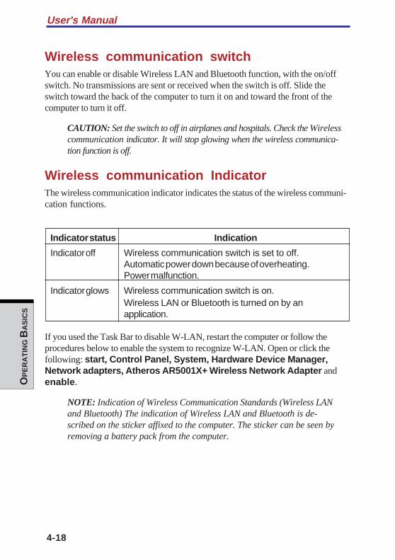
User's Manual
4-18
OP
ER
AT
ING B
AS
ICS
Wireless communication switchYou can enable or disable Wireless LAN and Bluetooth function, with the on/offswitch. No transmissions are sent or received when the switch is off. Slide theswitch toward the back of the computer to turn it on and toward the front of thecomputer to turn it off.
CAUTION: Set the switch to off in airplanes and hospitals. Check the Wirelesscommunication indicator. It will stop glowing when the wireless communica-tion function is off.
Wireless communication IndicatorThe wireless communication indicator indicates the status of the wireless communi-cation functions.
Indicator status Indication
Indicator off Wireless communication switch is set to off.Automatic power down because of overheating.Power malfunction.
Indicator glows Wireless communication switch is on.Wireless LAN or Bluetooth is turned on by anapplication.
If you used the Task Bar to disable W-LAN, restart the computer or follow theprocedures below to enable the system to recognize W-LAN. Open or click thefollowing: start, Control Panel, System, Hardware Device Manager,Network adapters, Atheros AR5001X+ Wireless Network Adapter andenable.
NOTE: Indication of Wireless Communication Standards (Wireless LANand Bluetooth) The indication of Wireless LAN and Bluetooth is de-scribed on the sticker affixed to the computer. The sticker can be seen byremoving a battery pack from the computer.

4-19
OP
ER
AT
ING B
AS
ICS
LANThe computer has built-in support for Ethernet LAN (10 megabits per second,10BASE-T) and Fast Ethernet LAN (100 megabits per second, 100BASE-Tx). Thissection describes how to connect/disconnect to a LAN.
CAUTION: Do not install or remove an optional memory module whileWake-up on LAN is enabled.
NOTE: Wake-up on LAN does not work without the AC adaptor. Leave itconnected, if you are using this feature.
LAN cable types
CAUTION: The computer must be configured properly before connectingto a LAN. Logging onto a LAN using the computer’s default settingscould cause a malfunction in LAN operation. Check with your LANadministrator regarding set-up procedures.
If you are using Fast Ethernet LAN (100 megabits per second, 100BASE-TX), besure to connect with a CAT5 cable. You cannot use a CAT3 cable.
If you are using Ethernet LAN (10 megabits per second, 10BASE-T), you canconnect with either a CAT5 or a CAT3.
Connecting LAN cableTo connect the LAN cable, follow the steps below.
CAUTION: Connect the AC adaptor before connecting the LAN cable. The ACadaptor must remain connected during LAN use. If you disconnect the ACAdaptor while the computer is accessing a LAN, the system may hang up.
1. Turn off the power to the computer and to all external devices connected tothe computer.
LAN

User's Manual
4-20
OP
ER
AT
ING B
AS
ICS
2. Plug one end of the cable into the LAN’s jack. Press gently until you hear thelatch click into place.
Figure 4-15 Connecting the LAN cable
3. Plug the other end of the cable into a LAN hub connector. Check with yourLAN administrator before connecting to a hub.
NOTE: When the computer is exchanging data with the LAN, the LANActive indicator glows orange. When the computer is connected to aLAN hub but is not exchanging data, the Link indicator glows green.
Disconnecting LAN cableTo disconnect the LAN cable, follow the steps below.
CAUTION: Make sure the LAN Active indicator (orange LED) is outbefore you disconnect the computer from the LAN.
1. Pinch the lever on the connector in the computer and pull out the connector.
2. Disconnect the cable from the LAN hub in the same manner. Check with yourLAN administrator before disconnecting from the hub.
LAN JACK
4-21
OP
ER
AT
ING B
AS
ICS
Using the microphonesYour computer has a built-in microphones that can be used to record stereo soundsinto your applications. It can also be used to issue voice commands to applicationsthat support such functions.
Since your computer has a built-in microphones and speaker, "howling" may beheard under certain conditions. Howling occurs when sound from the speaker ispicked up in the microphones and amplified back to the speaker, which amplifies itagain to the microphones.
This howling occurs repeatedly and causes a very loud, high-pitched noise. It is acommon phenomenon that occurs in any sound system when the microphonesinput is output to the speaker (throughput) and the speaker volume is too loud ortoo close to the microphones. You can control throughput by adjusting the volumeof your speaker or through the Mute function.
To adjust the volume or activate Mute, click start, point to All Programs, point toAccessories, point to Entertainment and click Volume Control. In theMaster Volume panel, you can use the slide bars to adjust the volume level orclick Mute at the bottom of the panel.
AudioThis section describes audio controls including sound levels and powermanagement.
Volume control
The Volume Control utility lets you control the audio volume in Windows for bothplayback and recording.
❑ To launch Volume Control for playback, click Start, point to All Programs,point to Accessories, point to Entertainment and click Volume Control.
❑ To launch Recording Control, click Options, point to Properties, chooseRecording and click OK.
❑ To view details of the Volume Control, click Help on the Volume Control.
Microphone level
The change the microphone gain, follow the steps below.
1. Click Start, point to All Programs, point to Accessories, point to Enter-tainment and click Volume Control.
Using the microphones

User's Manual
4-22
OP
ER
AT
ING B
AS
ICS
2. Click Options and select Advanced Controls.
3. Click Advanced.
4. Check the MIC Boost checkbox.
SoundMAX Control Panel
The SoundMAX control panel lets you control additional functions for theMicrophone Enhancement and Audio Power Management. To launch theSoundMAX Control Panel, follow the steps below.
1. Click Start and click Control Panel.
NOTE: If you are viewing the Control Panel in Category View, click onSwitch to Classic View.
2. Double-click the SoundMAX icon.
Microphone Enhancements
The Microphone Setup allows you to optimize the microphone input settings foryour particular configuration. Choose Standard Microphone if you have anordinary desktop microphone. Choose Headset if you have a wearable micro-phone that is positioned directly in front of your mouth.
NOTE: SoundMAX Superbeam™ Microphone is for an optionalmicrophone which is sold by Andrea Electronics. You can get informa-tion about the microphone at the web site of Andrea Electronics.
You can launch the Setup Wizard from the Control Panel to help you to automati-cally set proper microphone input volumes and ensure that your voice input(s) areworking correctly. As you speak into the microphone, the Sound Meter indicatesthe audio signal that your PC is receiving.
The Noise Reduction enhancement helps to eliminate ambient noise from thevoice input signal to provide a clean and clear signal to applications. This featurecan be used with any microphone.
NOTE: If the Noise Reduction check box is selected, a monauralsound is recorded when recording by a stereo microphone. You need todisable this check box if you would like to record a stereo sound by astereo microphone.
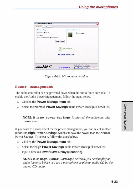
4-23
OP
ER
AT
ING B
AS
ICS
Figure 4-16 Microphone window
Power management
The audio controller can be powered down when the audio function is idle. Toenable the Audio Power Management, follow the steps below.
1. Clicked the Power Management tab.
2. Select the Normal Power Savings in the Power Mode pull-down list.
NOTE: If the No Power Savings is selected, the audio controlleralways runs.
If you want to a more effect for the power management, you can select anothermode, the High Power Savings which can save the power than the NormalPower Savings. To select it, follow the steps below.
1. Clicked the Power Management tab.
2. Select the High Power Savings in the Power Mode pull-down list.
3. Input a time in Power Save Delay (Seconds).
NOTE: If the High Power Saving is selected, you need to play anaudio file once before you use a microphone or play an audio CD by theanalog CD audio.
Using the microphones

User's Manual
4-24
OP
ER
AT
ING B
AS
ICS
Figure 4-17 Power Management window
Trademarks:
SoundMAX® and the SoundMAX logo are registered trademarks of AnalogDevices, Inc. PureAudio®, DSDA®, and Superbeam® are trademarks of AndreaElectronics. The Sensaura logo, Virtual Theater and Virtual Ear are trademarks and/or registered trademarks of Sensaura Limited. Yamaha XGlite is a trademark ofYamaha Corporation. All other trademarks are the property of their respectiveowners. All specifications subject to change without notice. © 2003 AnalogDevices, Inc. All Rights Reserved.
Using the internal modemIf you purchased a computer model with a preinstalled internal modem, read thissection for directions on connecting the modem. Refer to the online help files for theinternal modem and for details on operation of your modem and modem software.
NOTE: The internal modem does not support the voice functions.All data and fax functions are supported.
CAUTIONS: 1. In case of a lightning storm, unplug the modem cablefrom the telephone jack.
2. Do not connect the modem to a digital telephone line.A digital line will damage the modem.
4-25
OP
ER
AT
ING B
AS
ICS
Using the internal modem
Region selectionTelecommunication regulations vary from one region to another, so you will need tomake sure the internal modem’s settings are correct for the region in which it will beused.
1. Click start, point to All Programs, point to TOSHIBA, point to Network-ing and click Modem Region Select.
NOTE: Do not use the Country/Region Select function in the Modemsetup utility in the Control Panel if the function is available. If youchange the Country/Region in the Control Panel, the change may nottake effect.
2. The Region Selection icon will appear in the Windows Task Bar.
3. Click the icon with the primary mouse button to display a list of regions thatthe modem supports. A sub menu for telephony location information will alsobe displayed. A check will appear next to the currently selected region andtelephony location.
4. Select a region from the region menu or a telephony location from the sub-menu.
• When you click a region it becomes the modem’s region selection, and theNew Location for telephony will be set automatically.
• When you select a telephony location, the corresponding region is automati-cally selected and it becomes the modem’s current region setting.
Properties menuClick the icon with the secondary mouse button to display the following menu.
Setting
You can enable or disable the following settings:
AutoRun Mode
Region Select Utility starts automatically when you start up the operatingsystem.
User's Manual
4-26
OP
ER
AT
ING B
AS
ICS
Open the Dialing Properties dialog box after selecting region.
The dialing properties dialog box will be displayed automatically after youselect the region.
Location list for region selection.
A submenu appears displaying location information for telephony.
Open dialog box, if the modem and Telephony Current
Location region code do not match.
A warning dialog box is displayed if current settings for region code andtelephony location are incorrect.
Modem Selection
If the computer cannot recognize the internal modem, a dialog box is displayed.Select the COM port for your modem to use.
Dialing Properties
Select this item to display the dialing properties.
CAUTION: If you are using the computer in Japan, technical regulationsdescribed in the Telecommunications Business Law require that youselect Japan region mode. It is illegal to use the modem in Japan withany other selection.
ConnectingTo connect the internal modem cable, follow the steps below.
WARNING: The modular cable that comes with the computer must beused to connect a modem. Connect the end of the modular cable with thecore to the computer.
CAUTIONS: 1. In case of a lightning storm, unplug the modem cablefrom the telephone jack.
2. Do not connect the modem to a digital telephone line.A digital line will damage the modem.
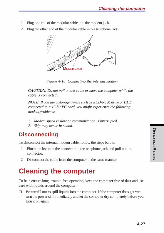
4-27
OP
ER
AT
ING B
AS
ICS
1. Plug one end of the modular cable into the modem jack.
2. Plug the other end of the modular cable into a telephone jack.
Figure 4-18 Connecting the internal modem
CAUTION: Do not pull on the cable or move the computer while thecable is connected.
NOTE: If you use a storage device such as a CD-ROM drive or HDDconnected to a 16-bit PC card, you might experience the followingmodem problems:
1. Modem speed is slow or communication is interrupted.2. Skip may occur in sound.
DisconnectingTo disconnect the internal modem cable, follow the steps below:
1. Pinch the lever on the connector in the telephone jack and pull out theconnector.
2. Disconnect the cable from the computer in the same manner.
Cleaning the computerTo help ensure long, trouble-free operation, keep the computer free of dust and usecare with liquids around the computer.
❑ Be careful not to spill liquids into the computer. If the computer does get wet,turn the power off immediately and let the computer dry completely before youturn it on again.
Cleaning the computer
MODEM JACK
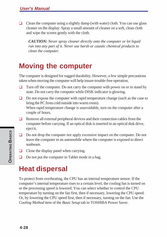
User's Manual
4-28
OP
ER
AT
ING B
AS
ICS
❑ Clean the computer using a slightly damp (with water) cloth. You can use glasscleaner on the display. Spray a small amount of cleaner on a soft, clean clothand wipe the screen gently with the cloth.
CAUTION: Never spray cleaner directly onto the computer or let liquidrun into any part of it. Never use harsh or caustic chemical products toclean the computer.
Moving the computerThe computer is designed for rugged durability. However, a few simple precautionstaken when moving the computer will help insure trouble-free operation.
❑ Turn off the computer. Do not carry the computer with power on or in stand bystate. Do not carry the computer while DISK indicator is glowing.
❑ Do not expose the computer with rapid temperature change (such as the case tobring the PC from cold outside into warm room).When rapid temperature change is unavoidable, turn on the computer after acouple of hours.
❑ Remove all external peripheral devices and their connection cables from thecomputer before carrying. If an optical disk is inserted in an optical disk drive,eject it.
❑ Do not drop the computer nor apply excessive impact on the computer. Do notleave the computer in an automobile where the computer is exposed to directsunbeam.
❑ Close the display panel when carrying.
❑ Do not put the computer in Tablet mode in a bag.
Heat dispersalTo protect from overheating, the CPU has an internal temperature sensor. If thecomputer’s internal temperature rises to a certain level, the cooling fan is turned onor the processing speed is lowered. You can select whether to control the CPUtemperature by turning on the fan first, then if necessary, lowering the CPU speed.Or, by lowering the CPU speed first, then if necessary, turning on the fan. Use theCooling Method item of the Basic Setup tab in TOSHIBA Power Saver.
4-29
OP
ER
AT
ING B
AS
ICS
Maximum Turn on the fan first, then if necessary, lower the CPUperformance processing speed.
Performance Use a combination of the fan and lowering the CPUprocessing speed.
Battery optimized Lower the CPU processing speed first, then if necessaryturn on the fan.
When the CPU temperature falls to a normal range, the fan is turned off and the CPUoperation returns to standard speed.
NOTE: If the CPU temperature reaches an unacceptably high level witheither setting, the system automatically shuts down to prevent damage.Data in memory will be lost.
Heat dispersal

User's Manual
4-30
OP
ER
AT
ING B
AS
ICS
TH
E KE
YB
OA
RD
Chapter 5
The Keyboard
Typewriter keys ................................................................................. 5-1F1 … F12 function keys ..................................................................... 5-2Soft keys: Fn key combinations ........................................................ 5-2Emulating keys on enhanced keyboard .............................................. 5-2Hotkeys .............................................................................................. 5-4Fn Sticky key ..................................................................................... 5-7
Windows special keys ....................................................................... 5-7Keypad overlay .................................................................................. 5-7Turning on the overlays ....................................................................... 5-7Temporarily using normal keyboard (overlay on) .................................. 5-8Temporarily using overlay (overlay off) ................................................. 5-9Temporarily changing modes .............................................................. 5-9
Generating ASCII characters ............................................................ 5-9

TH
E K
EY
BO
AR
D
5-1
TH
E KE
YB
OA
RD
Chapter 5
The KeyboardThe computer’s keyboard layouts are compatible with a 101/102-key enhancedkeyboard. By pressing some keys in combination, all the 101/102-key keyboardfunctions can be executed on the computer.
The number of keys on your keyboard depends on which country/region’skeyboard layout your computer is configured with. Keyboards for numerouslanguages are available.
There are five types of keys: typewriter keys, keypad overlay, function keys, softkeys and cursor control keys.
Typewriter keysThe typewriter keys, produce the upper- and lowercase letters, numbers, punctua-tion marks, and special symbols that appear on the screen.
There are some differences, however, between using a typewriter and using acomputer keyboard:
❑ Letters and numbers produced in computer text vary in width. Spaces, whichare created by a “space character,” may also vary depending on line justifica-tion and other factors.
❑ The lowercase l (el) and the number 1 (one) are not interchangeable oncomputers as they are on a typewriter.
❑ The uppercase O (oh) and the 0 (zero) are not interchangeable.
❑ The Caps Lock function key locks only the alphabetic characters in upper-case while the shift lock on a typewriter places all keys in the shifted position.
❑ The Shift keys, the Tab key, and the BkSp (backspace) key perform thesame function as their typewriter counterparts but also have special computerfunctions.
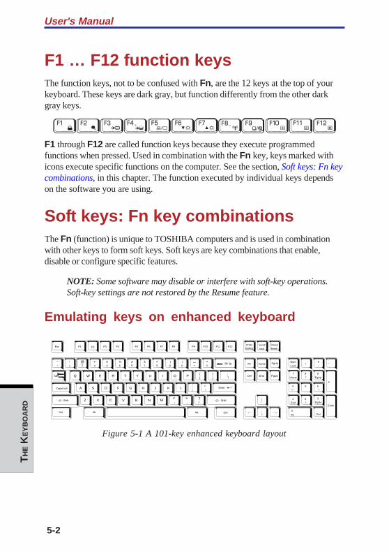
User's Manual
5-2
TH
E K
EY
BO
AR
D
F1 … F12 function keysThe function keys, not to be confused with Fn, are the 12 keys at the top of yourkeyboard. These keys are dark gray, but function differently from the other darkgray keys.
F1 through F12 are called function keys because they execute programmedfunctions when pressed. Used in combination with the Fn key, keys marked withicons execute specific functions on the computer. See the section, Soft keys: Fn keycombinations, in this chapter. The function executed by individual keys dependson the software you are using.
Soft keys: Fn key combinationsThe Fn (function) is unique to TOSHIBA computers and is used in combinationwith other keys to form soft keys. Soft keys are key combinations that enable,disable or configure specific features.
NOTE: Some software may disable or interfere with soft-key operations.Soft-key settings are not restored by the Resume feature.
Emulating keys on enhanced keyboard
Esc
#
3Home PgUpBk Sp
F1 F2 F3 F4 F5 F6 F7 F8 F9 F10 F11 F12
!
1 2$
4
%
5 6 8 (
9
)
0
&
7
_ +=
PgDnEnd
Shift
Del
Ins
CapsLock
Shift
Enter
Q W R T Y U I O P{[
}]
E
~
`
A S D F G H J K L:;
@
?/
> .
< ,MNVCXZ B
\
^ *
+
-
Tab
AltAlt
Enter
7
Home
8 9
PgUp
654
1
End
2 3
PgDn
0
Ins
Num
Lock
.
Del
PrtSc Scroll
lock
Pause
Break
CtrlCtrl
SysReg
/ *.
,,,
Figure 5-1 A 101-key enhanced keyboard layout
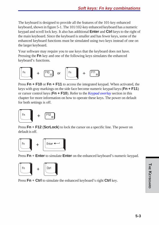
5-3
TH
E KE
YB
OA
RD
Soft keys: Fn key combinations
The keyboard is designed to provide all the features of the 101-key enhancedkeyboard, shown in figure 5-1. The 101/102-key enhanced keyboard has a numerickeypad and scroll lock key. It also has additional Enter and Ctrl keys to the right ofthe main keyboard. Since the keyboard is smaller and has fewer keys, some of theenhanced keyboard functions must be simulated using two keys instead of one onthe larger keyboard.
Your software may require you to use keys that the keyboard does not have.Pressing the Fn key and one of the following keys simulates the enhancedkeyboard’s functions.
Press Fn + F10 or Fn + F11 to access the integrated keypad. When activated, thekeys with gray markings on the side face become numeric keypad keys (Fn + F11)or cursor control keys (Fn + F10). Refer to the Keypad overlay section in thischapter for more information on how to operate these keys. The power on defaultfor both settings is off.
Press Fn + F12 (ScrLock) to lock the cursor on a specific line. The power ondefault is off.
Press Fn + Enter to simulate Enter on the enhanced keyboard’s numeric keypad.
Press Fn + Ctrl to simulate the enhanced keyboard’s right Ctrl key.
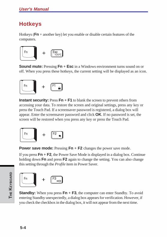
User's Manual
5-4
TH
E K
EY
BO
AR
D
Hotkeys
Hotkeys (Fn + another key) let you enable or disable certain features of thecomputers.
Sound mute: Pressing Fn + Esc in a Windows environment turns sound on oroff. When you press these hotkeys, the current setting will be displayed as an icon.
Instant security: Press Fn + F1 to blank the screen to prevent others fromaccessing your data. To restore the screen and original settings, press any key orpress the Touch Pad. If a screensaver password is registered, a dialog box willappear. Enter the screensaver password and click OK. If no password is set, thescreen will be restored when you press any key or press the Touch Pad.
Power save mode: Pressing Fn + F2 changes the power save mode.
If you press Fn + F2, the Power Save Mode is displayed in a dialog box. Continueholding down Fn and press F2 again to change the setting. You can also changethis setting through the Profile item in Power Saver.
Standby: When you press Fn + F3, the computer can enter Standby. To avoidentering Standby unexpectedly, a dialog box appears for verification. However, ifyou check the checkbox in the dialog box, it will not appear from the next time.
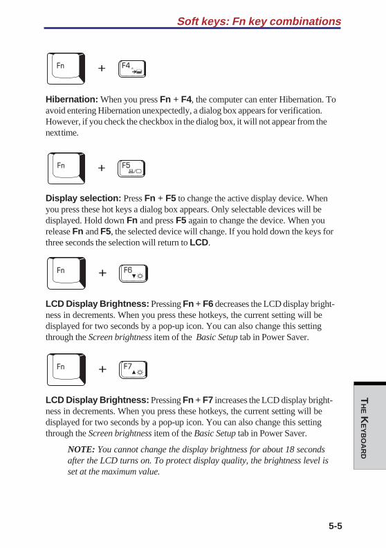
5-5
TH
E KE
YB
OA
RD
Soft keys: Fn key combinations
Hibernation: When you press Fn + F4, the computer can enter Hibernation. Toavoid entering Hibernation unexpectedly, a dialog box appears for verification.However, if you check the checkbox in the dialog box, it will not appear from thenext time.
Display selection: Press Fn + F5 to change the active display device. Whenyou press these hot keys a dialog box appears. Only selectable devices will bedisplayed. Hold down Fn and press F5 again to change the device. When yourelease Fn and F5, the selected device will change. If you hold down the keys forthree seconds the selection will return to LCD.
LCD Display Brightness: Pressing Fn + F6 decreases the LCD display bright-ness in decrements. When you press these hotkeys, the current setting will bedisplayed for two seconds by a pop-up icon. You can also change this settingthrough the Screen brightness item of the Basic Setup tab in Power Saver.
LCD Display Brightness: Pressing Fn + F7 increases the LCD display bright-ness in decrements. When you press these hotkeys, the current setting will bedisplayed for two seconds by a pop-up icon. You can also change this settingthrough the Screen brightness item of the Basic Setup tab in Power Saver.
NOTE: You cannot change the display brightness for about 18 secondsafter the LCD turns on. To protect display quality, the brightness level isset at the maximum value.
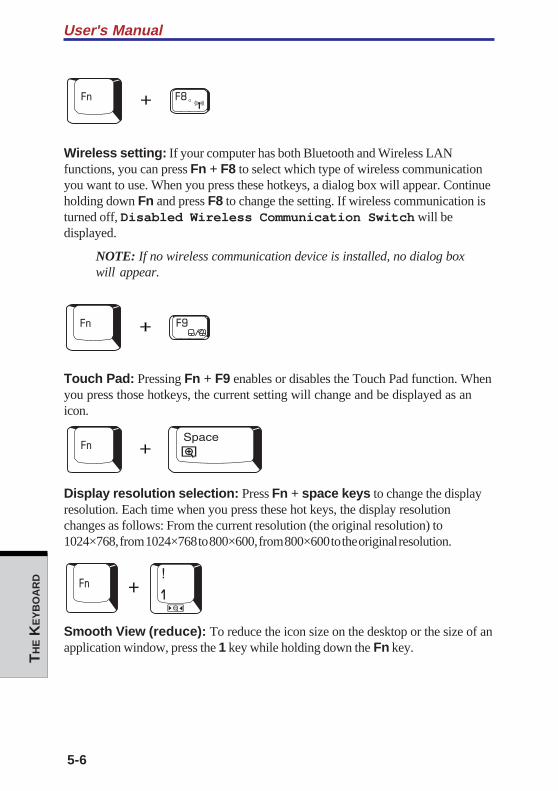
User's Manual
5-6
TH
E K
EY
BO
AR
D
Wireless setting: If your computer has both Bluetooth and Wireless LANfunctions, you can press Fn + F8 to select which type of wireless communicationyou want to use. When you press these hotkeys, a dialog box will appear. Continueholding down Fn and press F8 to change the setting. If wireless communication isturned off, Disabled Wireless Communication Switch will bedisplayed.
NOTE: If no wireless communication device is installed, no dialog boxwill appear.
Touch Pad: Pressing Fn + F9 enables or disables the Touch Pad function. Whenyou press those hotkeys, the current setting will change and be displayed as anicon.
Display resolution selection: Press Fn + space keys to change the displayresolution. Each time when you press these hot keys, the display resolutionchanges as follows: From the current resolution (the original resolution) to1024×768, from 1024×768 to 800×600, from 800×600 to the original resolution.
Smooth View (reduce): To reduce the icon size on the desktop or the size of anapplication window, press the 1 key while holding down the Fn key.
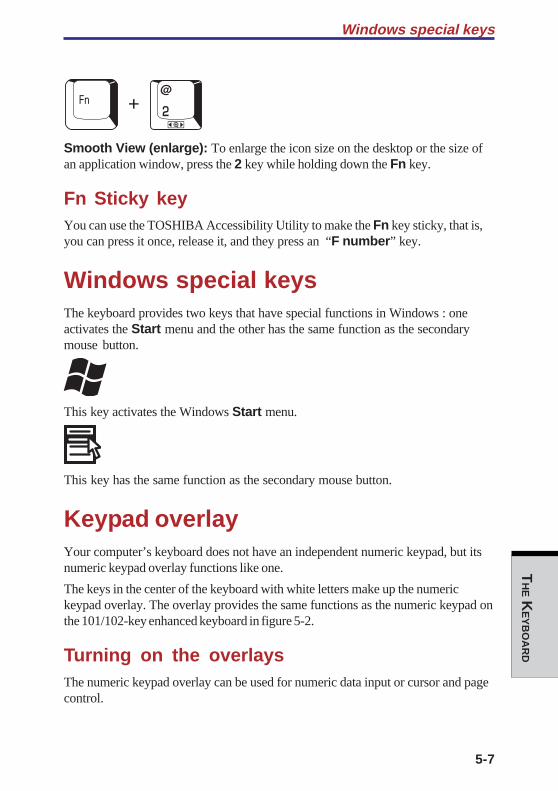
5-7
TH
E KE
YB
OA
RD
Windows special keys
Smooth View (enlarge): To enlarge the icon size on the desktop or the size ofan application window, press the 2 key while holding down the Fn key.
Fn Sticky keyYou can use the TOSHIBA Accessibility Utility to make the Fn key sticky, that is,you can press it once, release it, and they press an “F number” key.
Windows special keysThe keyboard provides two keys that have special functions in Windows : oneactivates the Start menu and the other has the same function as the secondarymouse button.
This key activates the Windows Start menu.
This key has the same function as the secondary mouse button.
Keypad overlayYour computer’s keyboard does not have an independent numeric keypad, but itsnumeric keypad overlay functions like one.
The keys in the center of the keyboard with white letters make up the numerickeypad overlay. The overlay provides the same functions as the numeric keypad onthe 101/102-key enhanced keyboard in figure 5-2.
Turning on the overlaysThe numeric keypad overlay can be used for numeric data input or cursor and pagecontrol.
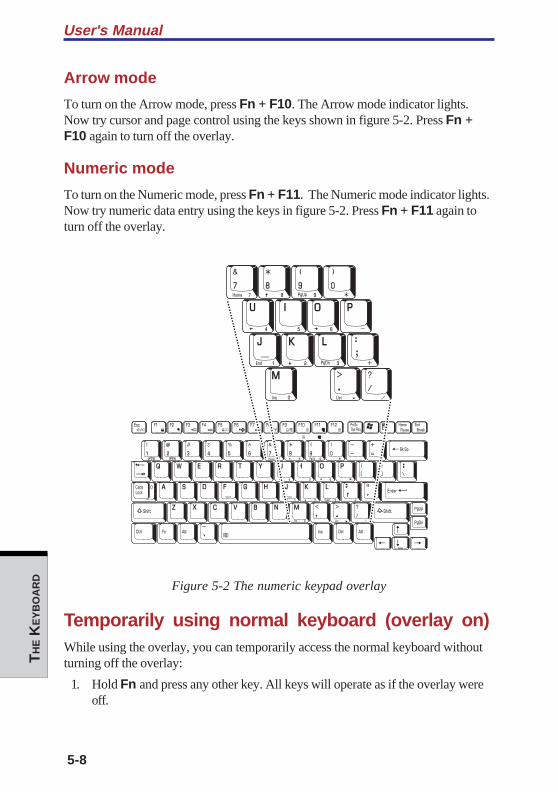
User's Manual
5-8
TH
E K
EY
BO
AR
D
Arrow mode
To turn on the Arrow mode, press Fn + F10. The Arrow mode indicator lights.Now try cursor and page control using the keys shown in figure 5-2. Press Fn +F10 again to turn off the overlay.
Numeric mode
To turn on the Numeric mode, press Fn + F11. The Numeric mode indicator lights.Now try numeric data entry using the keys in figure 5-2. Press Fn + F11 again toturn off the overlay.
Figure 5-2 The numeric keypad overlay
Temporarily using normal keyboard (overlay on)While using the overlay, you can temporarily access the normal keyboard withoutturning off the overlay:
1. Hold Fn and press any other key. All keys will operate as if the overlay wereoff.
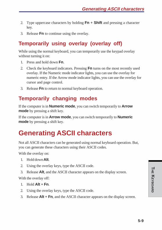
5-9
TH
E KE
YB
OA
RD
Generating ASCII characters
2. Type uppercase characters by holding Fn + Shift and pressing a characterkey.
3. Release Fn to continue using the overlay.
Temporarily using overlay (overlay off)While using the normal keyboard, you can temporarily use the keypad overlaywithout turning it on:
1. Press and hold down Fn.
2. Check the keyboard indicators. Pressing Fn turns on the most recently usedoverlay. If the Numeric mode indicator lights, you can use the overlay fornumeric entry. If the Arrow mode indicator lights, you can use the overlay forcursor and page control.
3. Release Fn to return to normal keyboard operation.
Temporarily changing modesIf the computer is in Numeric mode, you can switch temporarily to Arrowmode by pressing a shift key.
If the computer is in Arrow mode, you can switch temporarily to Numericmode by pressing a shift key.
Generating ASCII charactersNot all ASCII characters can be generated using normal keyboard operation. But,you can generate these characters using their ASCII codes.
With the overlay on:
1. Hold down Alt.
2. Using the overlay keys, type the ASCII code.
3. Release Alt, and the ASCII character appears on the display screen.
With the overlay off:
1. Hold Alt + Fn.
2. Using the overlay keys, type the ASCII code.
3. Release Alt + Fn, and the ASCII character appears on the display screen.

User's Manual
5-10
TH
E K
EY
BO
AR
D

PO
WE
R AN
D
PO
WE
R-UP M
OD
ES
Chapter 6
Power and Power-Up Modes
Power conditions ............................................................................... 6-1Power indicators ............................................................................... 6-3Battery indicators ............................................................................... 6-3DC IN 15V indicator ............................................................................ 6-3Power indicator ................................................................................... 6-4
Battery types ...................................................................................... 6-4Battery Pack ...................................................................................... 6-4Real time clock battery ....................................................................... 6-5
Care and use of the Battery Pack .................................................... 6-5Safety precautions .............................................................................. 6-6Charging the batteries ........................................................................ 6-9Monitoring battery capacity .............................................................. 6-10Maximizing battery operating time .................................................... 6-11Retaining data with power off ............................................................ 6-12Extending battery life ........................................................................ 6-12
Replacing the Battery Pack ............................................................ 6-13Removing the Battery Pack .............................................................. 6-13Installing the Battery Pack................................................................ 6-15
TOSHIBA Password Utility .............................................................. 6-16User password ................................................................................. 6-16Supervisor password ......................................................................... 6-17Starting the computer by password .................................................. 6-18
Tablet mode ..................................................................................... 6-18Power-up modes ............................................................................. 6-19Windows utilities .............................................................................. 6-19Hotkeys ............................................................................................ 6-19
Panel power off ............................................................................... 6-19System Auto Off ............................................................................... 6-20

PO
WE
R A
ND
PO
WE
R-U
P M
OD
ES
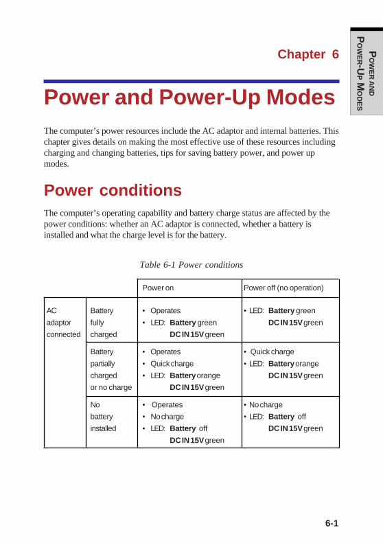
6-1
PO
WE
R AN
D
PO
WE
R-UP M
OD
ES
Chapter 6
Power and Power-Up ModesThe computer’s power resources include the AC adaptor and internal batteries. Thischapter gives details on making the most effective use of these resources includingcharging and changing batteries, tips for saving battery power, and power upmodes.
Power conditionsThe computer’s operating capability and battery charge status are affected by thepower conditions: whether an AC adaptor is connected, whether a battery isinstalled and what the charge level is for the battery.
Table 6-1 Power conditions
Power on Power off (no operation)
AC Battery • Operates • LED: Battery green
adaptor fully • LED: Battery green DC IN 15V green
connected charged DC IN 15V green
Battery • Operates • Quick charge
partially • Quick charge • LED: Battery orange
charged • LED: Battery orange DC IN 15V green
or no charge DC IN 15V green
No • Operates • No charge
battery • No charge • LED: Battery off
installed • LED: Battery off DC IN 15V green
DC IN 15V green
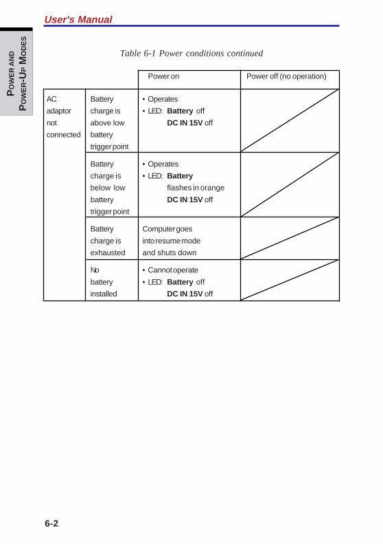
6-2
User's ManualP
OW
ER A
ND
PO
WE
R-U
P M
OD
ES
Table 6-1 Power conditions continued
Power on Power off (no operation)
AC Battery • Operates
adaptor charge is • LED: Battery off
not above low DC IN 15V off
connected battery
trigger point
Battery • Operates
charge is • LED: Battery
below low flashes in orange
battery DC IN 15V off
trigger point
Battery Computer goes
charge is into resume mode
exhausted and shuts down
No • Cannot operate
battery • LED: Battery off
installed DC IN 15V off
6-3
PO
WE
R AN
D
PO
WE
R-UP M
OD
ES
Power indicatorsThe Battery, DC IN 15V and Power indicators on the system indicator panelalert you to the computer’s operating capability and battery charge status.
Battery indicatorsCheck the Battery indicator to determine the status of the battery. The followingindicator lights indicate the battery status:
Flashing in orange The battery charge is low. The AC adaptor must beconnected to recharge the battery.
Orange Indicates the AC adaptor is connected and charging thebattery.
Green Indicates the AC adaptor is connected and the battery isfully charged.
No light Under any other conditions, the indicator does not light.
NOTE: If the battery becomes too hot while it is being charged, thecharge will stop and the battery indicator will go out. When the battery’stemperature falls to a normal range, charging will resume. This eventoccurs regardless of whether the power to the computer is on or off.
DC IN 15V indicatorCheck the DC IN 15V indicator to determine the power status with the AC adaptorconnected:
Green Indicates the AC adaptor is connected and supplyingproper power to the computer.
Flashing in orange Indicates a problem with the power supply. Plug the ACadaptor into another outlet. If it still does not operateproperly, contact TOSHIBA dealer. Refer to Chapter 9,Troubleshooting.
No light Under any other conditions, the indicator does not light.
Power indicators
6-4
User's ManualP
OW
ER A
ND
PO
WE
R-U
P M
OD
ES
Power indicatorCheck the Power indicator to determine the power status.
Green Indicates power is being supplied to the computer and thecomputer is turned on.
Blinking in orange Indicates the power was turned off while the computer wasin Resume mode. The indicator turns on for one secondand turns off for two seconds.
No light Under any other conditions, the indicator does not light.
Battery typesThe computer has two types of batteries:
❑ Battery Pack
❑ Real Time Clock (RTC) battery
Battery PackWhen the AC power cord is not connected, the computer’s main power source is aremovable lithium-ion Battery Pack, also referred to in this manual as the mainbattery. You can purchase Battery Packs for extended use of the computer awayfrom an AC power source.
CAUTIONS: 1. The Battery Pack is a lithium-ion battery, which canexplode if not properly replaced, used, handled ordisposed of. Dispose of the battery as required by localordinances or regulations. Use only battery recom-mended by TOSHIBA as replacements.
2. Do not remove the Battery Pack while the computer is inStandby mode. Data is stored in RAMs, so if the com-puter loses power it will be lost. When the computer ispowered off in Standby mode, and the AC adaptor is notconnected, the Battery Pack supplies power to maintaindata and program in memory. If the Battery Pack iscompletely discharged, Standby mode does not functionand the computer loses all data in memory.

6-5
PO
WE
R AN
D
PO
WE
R-UP M
OD
ES
To ensure that the Battery Pack maintains its maximum capacity, operate thecomputer on battery power at least once a month until the Battery Pack is fullydischarged. Refer to Extending battery life in this chapter for procedures. If thecomputer is continuously operated on AC power, through an AC adaptor for anextended period, more than a month, the battery may fail to retain a charge. It maynot function efficiently over the expected life of the battery and the Battery LEDmay not indicate a low-battery condition.
Real time clock batteryThe Real Time Clock (RTC) battery provides power for the internal real time clockand calendar. It also maintains the system configuration.
The RTC battery is charged when the power of the computer is on.
If the RTC battery becomes completely discharged, the system loses this data andthe real time clock and calendar stop working. The following message appears whenyou turn on the power:
*** Bad RTC battery ***Check system. Then press [F1] key . . . . . .
CAUTION: The computer’s RTC battery is a lithium ion battery andshould be replaced only by your dealer or by a TOSHIBA servicerepresentative. The battery can explode if not properly replaced, used,handled or disposed of. Dispose of the battery as required by localordinances or regulations.
NOTE: You can change the setting of RTC by pressing F1 key. Refer toChapter 9, Troubleshooting for the detail.
Care and use of the Battery PackThe Battery Pack is a vital component of portable computing. Taking proper care ofit will help ensure longer operating time on battery power as well as a longer life foryour Battery Pack. Follow the instructions in this section carefully to ensure safeoperation and maximum performance.
Care and use of the Battery Pack

6-6
User's ManualP
OW
ER A
ND
PO
WE
R-U
P M
OD
ES
Safety precautionsMishandling of batteries can cause death, serious injury or property damage.Carefully observe the following advisories:
Danger: Indicates an imminently hazardous situation, which could result in deathor serious injury, if you do not follow instructions.
Warning: Indicates a potentially hazardous situation, which could result it death orserious injury, if you do not follow instructions.
Caution: Indicates a potentially hazardous situation, which if not avoided, mayresult in moderate or minor injury of property damage.
Note: Provides important information.
Danger
1. Never try to dispose of the Battery Pack by burning or expose it to a heatingdevice such as a microwave oven. The Battery Pack could explode and causebodily injury.
2. Never try to disassemble, repair or otherwise tamper with a Battery Pack. TheBattery Pack will overheat and ignite. Leakage of caustic alkaline solution orother electrolytic substances will cause fire or injury, possibly resulting indeath or serious injury.
3. Never short-circuit the Battery Pack by contacting the terminals with a metalobject. A short-circuit can cause fire or otherwise damage the Battery Packand possibly cause injury. To avoid accidental short-circuit, always wrap theBattery Pack in plastic and cover the terminals with electrical tape whenstoring or disposing of the Battery Pack.
4. Never puncture the Battery Pack with a nail or other sharp object. Never strikeit with a hammer or other object. Never step on it.
5. Never try to charge the Battery Pack in any manner other than that describedin the user's manual. Never connect the Battery Pack to a plug socket or to aautomobile's cigarette lighter socket. It may rupture or ignite.
6. Use only the Battery Pack supplied with the computer or other device or aBattery Pack approved by the computer or device's manufacture. BatteryPacks have different voltages and terminal polarities. Use of an improperbattery could cause smoke, fire or rupture of the Battery Pack.

6-7
PO
WE
R AN
D
PO
WE
R-UP M
OD
ES
Care and use of the Battery Pack
7. Never subject a Battery Pack to heat, such as storage near a heat source.Exposure to heat can cause the Battery Pack to ignite, explode or leak causticliquid and cause death or serious injury. It could also fail or malfunctioncausing data loss.
8. Never expose the Battery Pack to abnormal shock, vibration or pressure. TheBattery Pack's internal protective device will fail, causing it to overheat,explode, ignite or leak caustic liquids possibly resulting in death or seriousinjury.
9. Never let a Battery Pack become wet. A wet Battery Pack will overheat, igniteor rupture possibly resulting in death or serious injury.
Warning
1. Never allow caustic electrolyte fluid leaked from a Battery Pack to contact youreyes, skin or clothing. If caustic electrolyte fluid should contact your eyes,immediately wash your eyes with large amounts of running water and seekmedical attention, to help prevent eye damage. It electrolyte fluid shouldcontact your skin immediately wash it under running water to prevent rash. If itcontacts your clothes, promptly remove them to prevent the fluid fromcontacting your skin or eyes.
2. Immediately turn off the power, disconnect the AC adapter and remove thebattery if any of the following events are observed in the Battery Pack:offensive or unusual odor, excessive heat, discoloration or deformation. Neveruse the computer again until it has been checked by a TOSHIBA serviceprovider. It might generate smoke or fire, or the Battery Pack might rupture.
3. Make sure the battery is securely installed in the computer before attemptingto charge the Battery Pack. Improper installation could generate smoke or fire,or cause the Battery Pack to rupture.
4. Keep the Battery Pack out of reach of infants and children. It can cause injury.

6-8
User's ManualP
OW
ER A
ND
PO
WE
R-U
P M
OD
ES
Caution
1. Never continue to use a Battery Pack after its recharging capacity has becomeimpaired, or after the display of a warning message indicating that the BatteryPack's power is exhausted. Continued use of an exhausted or impaired BatteryPack could cause the loss of data.
2. Never dispose of Battery Packs with normal trash. Bring them to yourTOSHIBA dealer or to another recycling center to save resources and preventenvironmental damage. Cover the terminals with electrical tape to preventshort-circuits, which could cause the Battery Pack to ignite or rupture
3. Use only Battery Pack recommended by TOSHIBA as replacements.
4. Always make sure the Battery Pack is installed correctly and securely.Otherwise, a Battery Pack could fall out and possibly cause injury.
5. Charge the Battery Pack only in an ambient temperature between 5 and 35degrees Celsius. Otherwise, the electrolyte solution might leak, Battery Packperformance might deteriorate and the battery life might be shortened.
6. Be sure to monitor the remaining battery power. If the Battery Pack and realtime clock battery discharge completely, Standby and Suspend will notfunction and data in memory will be lost. Also, the computer might register anincorrect time and date. In this case, connect the AC adaptor to recharge thebatteries
7. Never install or remove the Battery Pack without first turning off the powerand disconnecting the AC adaptor. Never remove the Battery Pack while thecomputer is in Suspend of Standby mode. Data will be lost.
Note
1. Never remove the Battery Pack while the Wake-up on LAN function isenabled. Data will be lost. Before you remove a Battery Pack, disable theWake-up on LAN function.
2. To ensure the Battery Pack maintains maximum capacity, operate the computeron battery power once a week until the Battery Pack is fully discharged. Referto the section Extending battery life in this chapter for procedures. If thecomputer is continuously operated on AC power for an extended period, morethan a week, the battery might fail to retain a charge. It might not functionefficiently over the expected life of the Battery Pack and the Battery indicatormight not indicate a low-battery condition.
3. After the Battery Pack is charged, avoid leaving the AC adaptor connectedand the computer turned off for more than a few hours at a time. Continuing tocharge a fully-charged Battery Pack can damage the battery.
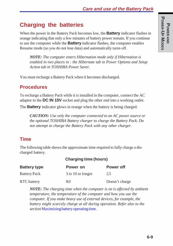
6-9
PO
WE
R AN
D
PO
WE
R-UP M
OD
ES
Charging the batteriesWhen the power in the Battery Pack becomes low, the Battery indicator flashes inorange indicating that only a few minutes of battery power remain. If you continueto use the computer while the Battery indicator flashes, the computer enablesResume mode (so you do not lose data) and automatically turns off.
NOTE: The computer enters Hibernation mode only if Hibernation isenabled in two places in : the Hibernate tab in Power Options and SetupAction tab in TOSHIBA Power Saver.
You must recharge a Battery Pack when it becomes discharged.
Procedures
To recharge a Battery Pack while it is installed in the computer, connect the ACadaptor to the DC IN 15V socket and plug the other end into a working outlet.
The Battery indicator glows in orange when the battery is being charged.
CAUTION: Use only the computer connected to an AC power source orthe optional TOSHIBA Battery charger to charge the Battery Pack. Donot attempt to charge the Battery Pack with any other charger.
Time
The following table shows the approximate time required to fully charge a dis-charged battery.
Charging time (hours)
Battery type Power on Power off
Battery Pack 3 to 10 or longer 2.5
RTC battery 8.0 Doesn’t charge
NOTE: The charging time when the computer is on is affected by ambienttemperature, the temperature of the computer and how you use thecomputer. If you make heavy use of external devices, for example, thebattery might scarcely charge at all during operation. Refer also to thesection Maximizing battery operating time.
Care and use of the Battery Pack
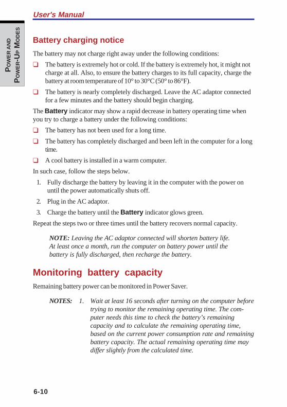
6-10
User's ManualP
OW
ER A
ND
PO
WE
R-U
P M
OD
ES
Battery charging notice
The battery may not charge right away under the following conditions:
❑ The battery is extremely hot or cold. If the battery is extremely hot, it might notcharge at all. Also, to ensure the battery charges to its full capacity, charge thebattery at room temperature of 10° to 30°C (50° to 86°F).
❑ The battery is nearly completely discharged. Leave the AC adaptor connectedfor a few minutes and the battery should begin charging.
The Battery indicator may show a rapid decrease in battery operating time whenyou try to charge a battery under the following conditions:
❑ The battery has not been used for a long time.
❑ The battery has completely discharged and been left in the computer for a longtime.
❑ A cool battery is installed in a warm computer.
In such case, follow the steps below.
1. Fully discharge the battery by leaving it in the computer with the power onuntil the power automatically shuts off.
2. Plug in the AC adaptor.
3. Charge the battery until the Battery indicator glows green.
Repeat the steps two or three times until the battery recovers normal capacity.
NOTE: Leaving the AC adaptor connected will shorten battery life.At least once a month, run the computer on battery power until thebattery is fully discharged, then recharge the battery.
Monitoring battery capacityRemaining battery power can be monitored in Power Saver.
NOTES: 1. Wait at least 16 seconds after turning on the computer beforetrying to monitor the remaining operating time. The com-puter needs this time to check the battery’s remainingcapacity and to calculate the remaining operating time,based on the current power consumption rate and remainingbattery capacity. The actual remaining operating time maydiffer slightly from the calculated time.
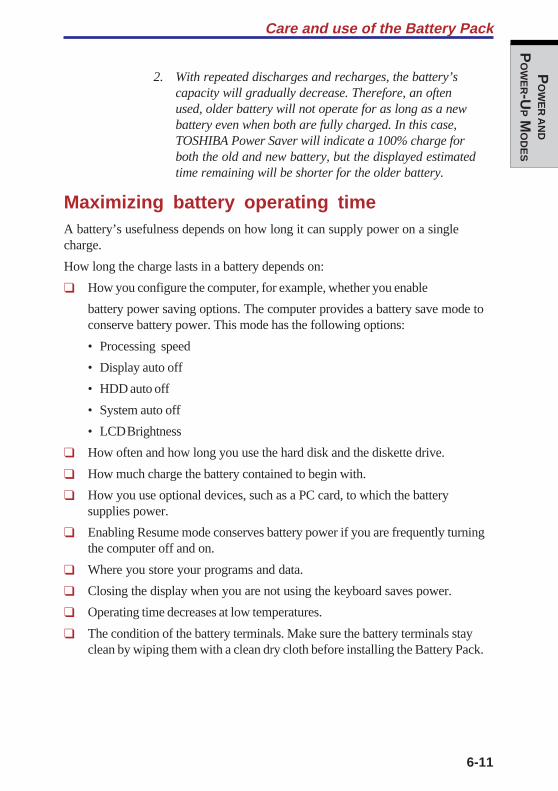
6-11
PO
WE
R AN
D
PO
WE
R-UP M
OD
ES
Care and use of the Battery Pack
2. With repeated discharges and recharges, the battery’scapacity will gradually decrease. Therefore, an oftenused, older battery will not operate for as long as a newbattery even when both are fully charged. In this case,TOSHIBA Power Saver will indicate a 100% charge forboth the old and new battery, but the displayed estimatedtime remaining will be shorter for the older battery.
Maximizing battery operating timeA battery’s usefulness depends on how long it can supply power on a singlecharge.
How long the charge lasts in a battery depends on:
❑ How you configure the computer, for example, whether you enable
battery power saving options. The computer provides a battery save mode toconserve battery power. This mode has the following options:
• Processing speed
• Display auto off
• HDD auto off
• System auto off
• LCD Brightness
❑ How often and how long you use the hard disk and the diskette drive.
❑ How much charge the battery contained to begin with.
❑ How you use optional devices, such as a PC card, to which the batterysupplies power.
❑ Enabling Resume mode conserves battery power if you are frequently turningthe computer off and on.
❑ Where you store your programs and data.
❑ Closing the display when you are not using the keyboard saves power.
❑ Operating time decreases at low temperatures.
❑ The condition of the battery terminals. Make sure the battery terminals stayclean by wiping them with a clean dry cloth before installing the Battery Pack.

6-12
User's ManualP
OW
ER A
ND
PO
WE
R-U
P M
OD
ES
Retaining data with power offWhen you turn off your computer with fully charged batteries, the batteries retaindata for the following approximate time periods:
Battery pack (4400 mAh) 7 days (Resume mode)30 days (Boot mode)
RTC battery 1 month
Extending battery lifeTo maximize the life of your Battery Pack:
❑ At least once a month, disconnect the computer from a power source andoperate it on battery power until the Battery Pack fully discharges. Beforedoing so, follow the steps below.
1. Turn off the computer’s power.
2. Disconnect the AC adaptor and turn on the computer’s power. If it does notturn on go to step 4.
3. Operate the computer on battery power for five minutes. If the Battery Packhas at least five minutes of operating time, continue operating until theBattery Pack is fully discharged. If the Battery indicator flashes or there issome other warning to indicate a low battery, go to step 4.
4. Connect the AC adaptor to the computer and the power cord to a poweroutlet. The DC IN 15V indicator should glow in green, and the Batteryshould glow in orange to indicate that the Battery Pack is being charged. Ifthe DC IN 15V indicator does not glow, power is not being supplied. Checkthe connections for the AC adaptor and power cord.
5. Charge the Battery Pack until the Battery indicator glows in green.
❑ If you have spare Battery Packs, rotate their use.
❑ If you will not be using the system for an extended period, more than onemonth, remove the Battery Pack.
❑ Disconnect the AC adaptor when the battery is fully charged. Overchargingmakes the battery hot and shortens life.
❑ If you are not going to use the computer for more than eight hours, disconnectthe AC adaptor.
❑ Store spare Battery Packs in a cool dry place out of direct sunlight.

6-13
PO
WE
R AN
D
PO
WE
R-UP M
OD
ES
Replacing the Battery PackWhen the Battery Pack reaches the end of its operating life you will need to install anew one. The life of the Battery Pack is generally about 500 recharges. If theBattery indicator flashes in orange shortly after fully recharging the battery, theBattery Pack needs to be replaced.
You might also replace a discharged Battery Pack with a charged spare when youare operating your computer away from an AC power source. This section explainshow to remove and install Battery Packs.
NOTE: Place a mat beneath the computer to prevent making a scratchon the lid when replacing the Battery Pack. Avoid the mat that generatesstatic electricity.
Removing the Battery PackTo replace a discharged Battery Pack, follow the steps below.
CAUTIONS: 1. When handling Battery Packs, be careful not to shortcircuit the terminals. Also do not drop, hit or otherwiseapply impact; do not scratch or break the casing and donot twist or bend the Battery Pack
2. Do not remove the Battery Pack while the computer is inStandby mode. Data is stored in RAM, so if the computerloses power it will be lost.
3. In Hibernation mode, data will be lost if you remove thebattery or disconnect the AC adaptor before the save iscompleted. Wait for the Disk indicator to go out.
1. Save your work.
2. Turn the computer’s power off. Make sure the Power indicator is off.
3. Remove all cables connected to the computer.
4. Turn the computer upside down with the front side of the computer facing toyou.
5. Release the battery lock.
6. Slide the battery release latch to free the Battery Pack for removal.
Replacing the Battery Pack
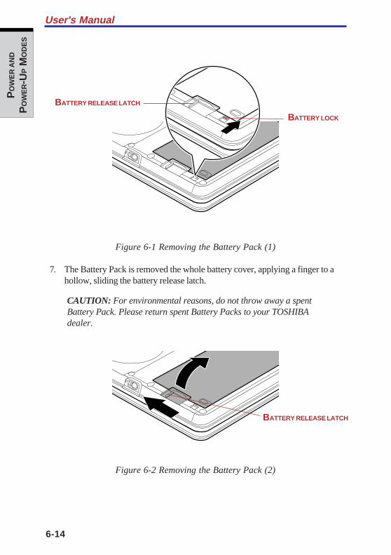
6-14
User's ManualP
OW
ER A
ND
PO
WE
R-U
P M
OD
ES
Figure 6-1 Removing the Battery Pack (1)
7. The Battery Pack is removed the whole battery cover, applying a finger to ahollow, sliding the battery release latch.
CAUTION: For environmental reasons, do not throw away a spentBattery Pack. Please return spent Battery Packs to your TOSHIBAdealer.
Figure 6-2 Removing the Battery Pack (2)
BATTERY LOCK
BATTERY RELEASE LATCH
BATTERY RELEASE LATCH
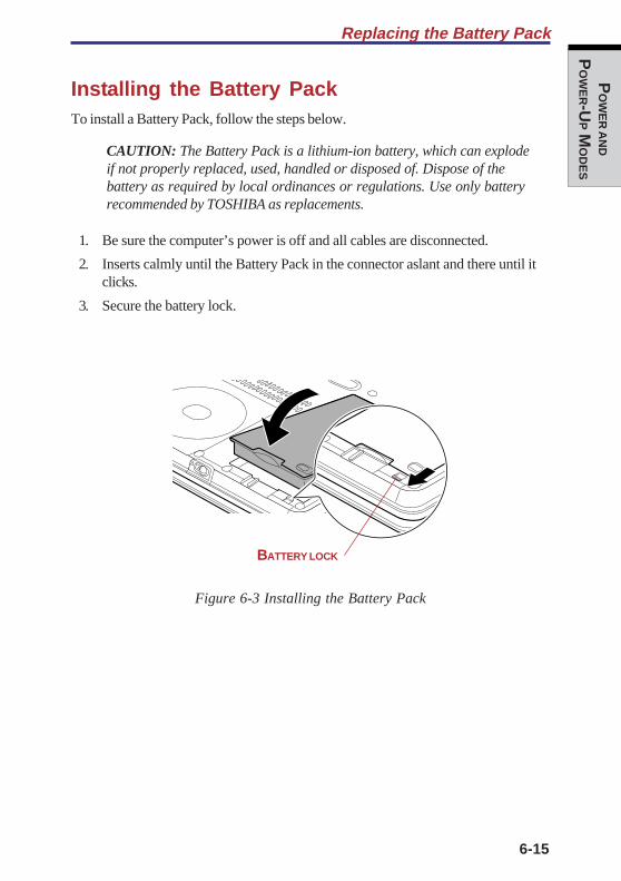
6-15
PO
WE
R AN
D
PO
WE
R-UP M
OD
ES
Installing the Battery PackTo install a Battery Pack, follow the steps below.
CAUTION: The Battery Pack is a lithium-ion battery, which can explodeif not properly replaced, used, handled or disposed of. Dispose of thebattery as required by local ordinances or regulations. Use only batteryrecommended by TOSHIBA as replacements.
1. Be sure the computer’s power is off and all cables are disconnected.
2. Inserts calmly until the Battery Pack in the connector aslant and there until itclicks.
3. Secure the battery lock.
Figure 6-3 Installing the Battery Pack
Replacing the Battery Pack
BATTERY LOCK
6-16
User's ManualP
OW
ER A
ND
PO
WE
R-U
P M
OD
ES
TOSHIBA Password UtilityThe TOSHIBA Password Utility provides two levels of password security: User andSupervisor.
NOTE: Passwords set in TOSHIBA Password Utility are different fromthe Windows password.
User passwordTo start the utility, point to or click the following items:
Start -> All Programs -> TOSHIBA Utilities ->
TOSHIBA Password Utility
The user password dialog box contains two main fields: User Passwordand User Token.
User Password field
❑ Set (button)Click this button to register a password of up to 50 characters. After a pass-word is set, you will be prompted to enter it when you start the computer.
NOTE: After you set the password, a dialog box will be displayed askingwhether you want to save it to a diskette or other media. If you forget thepassword, you can open the password file on another computer. Be sureto keep the media in a safe place.
❑ Delete (button)Click this button to delete a registered password. Before you can delete apassword, you must first enter the current password correctly or insert a propertoken.
❑ Change (button)Click this button to change a registered password. Before you can change apassword, you must first enter the current password correctly or insert a propertoken.
❑ Owner String (text box)You can use this box to associate text with the password. After you enter text,click Apply or OK. The text will be displayed when you are prompted to enter apassword.
6-17
PO
WE
R AN
D
PO
WE
R-UP M
OD
ES
User Token field
❑ Create (button)You can use an SD card token, instead of entering the password. After youhave registered a password, insert an SD card and click Create. You can usean SD card of any capacity, but it must be formatted correctly.
If an unformatted card or one with an incompatible format is inserted, you willbe prompted to format it with a tool named TOSHIBA SD Memory Card Format.To start the format tool, point to or click the following items:
Start -> All Programs -> TOSHIBA SD Card
Utilities -> TOSHIBA SD Memory Card Format
CAUTION: When you format an SD Memory card, all data will bedeleted. Be sure to save data on the card to other media before youformat the card.
❑ Disable (button)Click this button to invalidate the token. You cannot revalidate old tokens, butyou can use the same SD cards to create new tokens.
Supervisor passwordIf you set a supervisor password, some functions might be restricted when a userlogs on with the user password. To set a supervisor password, execute the fileTOSUP.EXE. The file is located at:
C:\Program Files\Toshiba\WindowsUtilities\SVPWTool\TOSUP.EXE
This utility lets you do the following:
❑ Register, delete or change the supervisor password.
❑ Create or invalidate a supervisor token
NOTE: This function in the TOSHIBA password utility lets you invali-date only supervisor tokens or all tokens, including user and supervisortokens.
❑ Specify restrictions for general users.
TOSHIBA Password Utility

6-18
User's ManualP
OW
ER A
ND
PO
WE
R-U
P M
OD
ES
Starting the computer by passwordIf you registered a password, there are two ways to start the computer:
❑ Insert a password token before you turn on the computer. The computer willstart normally, without displaying a password prompt.
❑ Enter the password manually.
NOTE: The password is necessary only if the computer was shut down inboot mode. It is not needed in Hibernation or Standby mode.
To enter a password manually, follow these steps:
1. Turn on the power as described in Chapter 3, Getting Started. The followingmessage will appear in the LCD:Password=
2. Enter the Password.
3. Press Enter.
NOTE: If you enter the password incorrectly three times in a row, thecomputer shuts off. In this case, you must turn the computer back on toretry password entry.
Tablet modeEnter your password by tapping the on-screen keyboard using the tablet pen.
Figure 6-4 On-screen keyboard
6-19
PO
WE
R AN
D
PO
WE
R-UP M
OD
ES
❑ The beep sounds when tapping the on-screen keyboard with the tablet pen.An * (asterisk) is displayed after "Password =" and one character is input forevery tapping.
NOTE: Register your password to the computer in the laptop mode usingthe standard keyboard. Refer to Chapter 7, HW Setup for the detail.
Power-up modesThe computer has the following power-up modes:
❑ Boot: Computer shuts down without saving data. Always save your workbefore you turn the computer off in boot mode.
❑ Hibernation: Data in memory is saved to the hard disk.
❑ Standby: Data is maintained in the computer's main memory.
NOTE: Refer also to the sections Turning on the power and Turning offthe power in Chapter 3, Getting Started.
Windows utilitiesYou can specify the setting in TOSHIBA Power Saver.
HotkeysYou can use hotkeys Fn + F3 to enter Standby mode and Fn + F4 to enter Hiberna-tion. See Chapter 5, The Keyboard for details.
Panel power offYou can set up your computer so that power turns off automatically when you closethe display panel. When you open the panel, power turns on in Standby orHibernation mode but not in boot mode.
However, when the system is running in the tablet mode, it does not shut downeven if the display panel is closed.
NOTE: If the panel power off function is enabled and you use Shut downWindows, do not close the display until the shut down function iscompleted.
Power-up modes

6-20
User's ManualP
OW
ER A
ND
PO
WE
R-U
P M
OD
ES
System Auto OffThis feature turns the system off automatically if the computer is not used for a setduration. The system shuts down in Standby mode or Hibernation mode in Windows.
However, when the system is running in the tablet mode, it does not shut downeven if the display panel is closed.
HW
SE
TU
P
Chapter 7
HW SetupHW Setup ........................................................................................... 7-1Accessing HW Setup ......................................................................... 7-1HW Setup window .............................................................................. 7-1

HW
SE
TU
P
7-1
HW
SE
TU
P
Chapter 7
HW SetupThis chapter explains how to use TOSHIBA HW Setup program to configure yourcomputer. TOSHIBA HW Setup lets you configure settings for display, CPU, bootpriority, Keyboard, USB, LAN, general and device configuration.
Accessing HW SetupTo run HW Setup, click start, click Control Panel, click Printers and OtherHardware and select TOSHIBA HW Setup.
HW Setup windowThe HW Setup window contains the following tabs: Display, CPU, Boot Priority,Keyboard, USB, LAN, General, Device Config.
General
This window displays the BIOS version and contains two buttons: Default andAbout.
Default Return all HW Setup values to the factory settings.
About Display the HW Setup version.
Setup
This field displays BIOS Version and date.

User's Manual
7-2
HW
SE
TU
P
Device Config
Device Configuration
This option lets you set the device configuration.
All Devices BIOS sets all devices.
Setup by OS Operating system sets devices that it can control. (Default)
Display
This tab lets you customize your computer’s display settings for either the internalLCD screen or for an external monitor.
Power On Display
Lets you set the display to be used when the computer is booted.
Auto-Selected Selects an external monitor if one is connected. Other-wise, it selects the internal LCD. (Default)
LCD+Analog RGB Selects both the internal LCD and external monitor forsimultaneous display.
System LCD Only Selects the internal LCD even if the external monitor isconnected.
CPU
Dynamic CPU Frequency Mode
This option lets you choose from the following settings:
Dynamically Switchable CPU power consumption and clock speedautomatic switching function is enabled.When the computer is in use, CPU operationis automatically switched when necessary.(Default)
Always High CPU power consumption and clock speedautomatic switching function is disabled. TheCPU always runs at its fastest speed.
Always Low CPU power consumption and clock speedautomatic switching function is disabled. TheCPU always runs at low power consumptionand low speed.

7-3
HW
SE
TU
P
Boot Priority
Boot Priority Options
This option sets the priority for booting the computer. Select from the followingsettings:
HDD −> −> −> −> −> FDD −> −> −> −> −> CD-ROM −> −> −> −> −> LAN The computer looks for bootable files inthe following order: HDD, diskette drive*1,CD-ROM*2 and LAN. (Default)
FDD −> −> −> −> −> HDD −> −> −> −> −> CD-ROM −> −> −> −> −> LAN The computer looks for bootable files inthe following order: diskette drive*1, HDD,CD-ROM*2 and LAN.
HDD −> −> −> −> −> CD-ROM −> −> −> −> −> LAN −> −> −> −> −> FDD The computer looks for bootable files inthe following order: HDD, CD-ROM*2 ,LAN and diskette drive*1.
FDD −> −> −> −> −> CD-ROM −> −> −> −> −> LAN −> −> −> −> −> HDD The computer looks for bootable files inthe following order: diskette drive*1, CD-ROM*2 , LAN and HDD.
CD-ROM −> −> −> −> −> LAN −> −> −> −> −> HDD −> −> −> −> −> FDD The computer looks for bootable files inthe following order: CD-ROM*2 , LAN,HDD, diskette drive*1.
CD-ROM −> −> −> −> −> LAN −> −> −> −> −> FDD −> −> −> −> −> HDD The computer looks for bootable files inthe following order: CD-ROM*2 , LAN,diskette drive*1 and HDD.
*1 FDD is looked for when the boot disk is contained in external FDD. When SDmemory card is set as the boot disk, external FDD is looked for first. Next, SDmemory card is looked for.
*2 The CD-ROM is available only with the optional optical disk drive.
You can override the settings and manually select a boot device in one of thefollowing two ways.
❑ Press one of the following keys while the computer is booted:
U Selects the USB diskette drive.
N Selects the Network.
1 Selects the primary HDD.
P Selects the PC card HDD.
C Selects the CD-ROM*1.
HW Setup

User's Manual
7-4
HW
SE
TU
P
This procedure does not affect the settings.
❑ Use hot keys.
1. Hold down F12 and boot the computer.
2. The following menu will be displayed with the following icons: Built-in HDD,CD-ROM, FDD ( or SD memory card), Network (LAN), PCA (ATA) card boot.
NOTE: A bar will appear only under the selected device.
3. Use the left/right cursor keys to highlight the boot device you want and pressEnter.
NOTES: 1. If a supervisor password is set, the menu above does notappear when you use the user password to start thecomputer.
2. The selection method above does not change the bootpriority settings in HW Setup.
3. If you press a key other than one of those above or if theselected device is not installed, the system will boot accordingto the current setting in HW Setup.
HDD Priority Options
This option sets the priority for booting the computer from the HDD. Select from thefollowing settings:
Built-in HDD −> −> −> −> −> PC Card (Default)The computer will look for the Built-in HDD first, next thethe PC Card (Default).
PC Card −> −> −> −> −> Built-in HDDThe computer will look for the PC Card first, next the Built-in HDD.
NOTE: If a boot command is not found on the first detected HDD, thesystem will not boot from the other HDD. It will search the next device inthe boot priority for a boot command.
7-5
HW
SE
TU
PHW Setup
Network Boot Protocol
This feature sets the protocol to remotely boot from the network.
[PXE] Sets PXE as the protocol. (Default)
[RPL] Sets RPL as the protocol.
NOTES: 1. PC card HDD boot is supported only by the PC card sloton the computer. Support is guaranteed only for TOSHIBAPC card HDDs.
2. When you assign a PC card HDD top priority, “PC” is notdisplayed. However, the PC card HDD takes the position ofHDD in the Boot Priority Options list above.
Keyboard
Wake-up on Keyboard
When this feature is enabled and the computer is in Standby mode, you can turn onthe computer by pressing any key. It is effective only for the internal keyboard andonly when the computer is in Standby mode.
Enabled Enables the Wake-up on Keyboard.
Disabled Disables the Wake-up on Keyboard. (Default)
USB
USB KB/Mouse Legacy Emulation
Use this option to enable or disable USB KB/Mouse Legacy Emulation. If youroperating system does not support USB, you can still use a USB mouse andkeyboard by setting the USB KB/Mouse Legacy Emulation item toEnabled.
Enabled Enables the USB KB/Mouse Legacy Emulation. (Default)
Disabled Disables the USB KB/Mouse Legacy Emulation.

User's Manual
7-6
HW
SE
TU
P
USB-FDD Legacy Emulation
Use this option to enable or disable USB-FDD Legacy Emulation.
Enabled Enables the USB-FDD Legacy Emulation. (Default)
Disabled Disables the USB-FDD Legacy Emulation.
LAN
Wake-up on LAN
This features lets the computer’s power be turned on when it receives a wake-upsignal from the LAN.
Enabled Enables Wake-up on LAN.
Disabled Disables Wake-up on LAN. (Default)
CAUTION: Do not install or remove an optional memory module whileWake-up on LAN is enabled.
NOTE: Wake-up on LAN does not work without the AC adaptor. Leave itconnected, if you are using this feature.
Built-in LAN
Enabled Enables built-in LAN functions. (Default)
Disabled Disables built-in LAN functions.
OP
TIO
NA
L DE
VIC
ES
Chapter 8
Optional Devices
PC cards ............................................................................................. 8-2Inserting a PC card ............................................................................. 8-2Removing a PC card ........................................................................... 8-3
SD cards ............................................................................................. 8-3Inserting an SD card ........................................................................... 8-4Removing an SD card ......................................................................... 8-4
Memory expansion ............................................................................ 8-6Installing memory module ................................................................... 8-7Removing memory module.................................................................. 8-9
Battery Pack ..................................................................................... 8-10Universal AC Adaptor ...................................................................... 8-10Battery Charger ............................................................................... 8-11USB diskette Kit ............................................................................... 8-11Tablet Multi Dock ............................................................................. 8-11External monitor .............................................................................. 8-12Tablet PC Pen set ............................................................................ 8-12Reserve pen ..................................................................................... 8-12Security lock .................................................................................... 8-13

OP
TIO
NA
L D
EV
ICE
S
8-1
OP
TIO
NA
L DE
VIC
ES
Chapter 8
Optional DevicesOptional devices can expand the computer’s capabilities and its versatility. Thefollowing optional devices are available from your TOSHIBA dealer:
Cards/memory❑ PC cards
❑ SD cards
❑ Memory module
Power devices❑ Battery Pack
❑ Universal AC Adaptor
❑ Battery Charger
Peripheral devices❑ Hard disk drive pack
❑ USB diskette Kit
❑ Tablet Multi Dock
❑ External monitor
❑ Tablet PC Pen set
❑ Reserve Pen
Other❑ Security lock
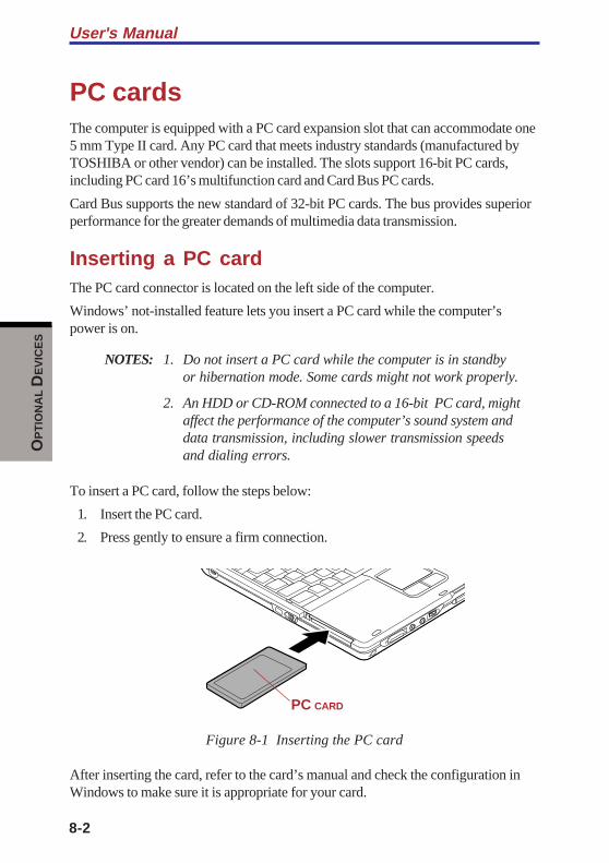
8-2
User's ManualO
PT
ION
AL D
EV
ICE
S
PC cardsThe computer is equipped with a PC card expansion slot that can accommodate one5 mm Type II card. Any PC card that meets industry standards (manufactured byTOSHIBA or other vendor) can be installed. The slots support 16-bit PC cards,including PC card 16’s multifunction card and Card Bus PC cards.
Card Bus supports the new standard of 32-bit PC cards. The bus provides superiorperformance for the greater demands of multimedia data transmission.
Inserting a PC cardThe PC card connector is located on the left side of the computer.
Windows’ not-installed feature lets you insert a PC card while the computer’spower is on.
NOTES: 1. Do not insert a PC card while the computer is in standbyor hibernation mode. Some cards might not work properly.
2. An HDD or CD-ROM connected to a 16-bit PC card, mightaffect the performance of the computer’s sound system anddata transmission, including slower transmission speedsand dialing errors.
To insert a PC card, follow the steps below:
1. Insert the PC card.
2. Press gently to ensure a firm connection.
Figure 8-1 Inserting the PC card
After inserting the card, refer to the card’s manual and check the configuration inWindows to make sure it is appropriate for your card.
PC CARD
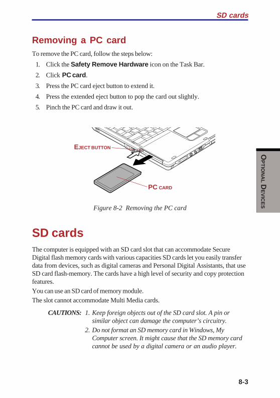
8-3
OP
TIO
NA
L DE
VIC
ES
SD cards
Removing a PC cardTo remove the PC card, follow the steps below:
1. Click the Safety Remove Hardware icon on the Task Bar.
2. Click PC card.
3. Press the PC card eject button to extend it.
4. Press the extended eject button to pop the card out slightly.
5. Pinch the PC card and draw it out.
Figure 8-2 Removing the PC card
SD cardsThe computer is equipped with an SD card slot that can accommodate SecureDigital flash memory cards with various capacities SD cards let you easily transferdata from devices, such as digital cameras and Personal Digital Assistants, that useSD card flash-memory. The cards have a high level of security and copy protectionfeatures.
You can use an SD card of memory module.The slot cannot accommodate Multi Media cards.
CAUTIONS: 1. Keep foreign objects out of the SD card slot. A pin orsimilar object can damage the computer’s circuitry.
2. Do not format an SD memory card in Windows, MyComputer screen. It might cause that the SD memory cardcannot be used by a digital camera or an audio player.
EJECT BUTTON
PC CARD
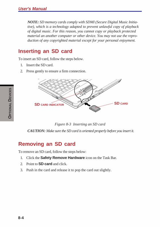
8-4
User's ManualO
PT
ION
AL D
EV
ICE
S
NOTE: SD memory cards comply with SDMI (Secure Digital Music Initia-tive), which is a technology adapted to prevent unlawful copy of playbackof digital music. For this reason, you cannot copy or playback protectedmaterial an another computer or other device. You may not use the repro-duction of any copyrighted material except for your personal enjoyment.
Inserting an SD cardTo insert an SD card, follow the steps below.
1. Insert the SD card.
2. Press gently to ensure a firm connection.
Figure 8-3 Inserting an SD card
CAUTION: Make sure the SD card is oriented properly before you insert it.
Removing an SD cardTo remove an SD card, follow the steps below:
1. Click the Safety Remove Hardware icon on the Task Bar.
2. Point to SD card and click.
3. Push in the card and release it to pop the card out slightly.
SD CARDSD CARD INDICATOR
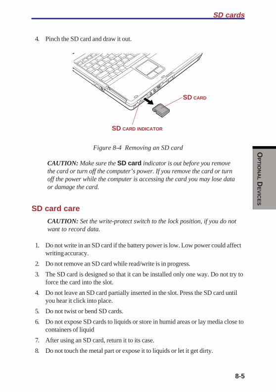
8-5
OP
TIO
NA
L DE
VIC
ES
SD cards
4. Pinch the SD card and draw it out.
Figure 8-4 Removing an SD card
CAUTION: Make sure the SD card indicator is out before you removethe card or turn off the computer’s power. If you remove the card or turnoff the power while the computer is accessing the card you may lose dataor damage the card.
SD card care
CAUTION: Set the write-protect switch to the lock position, if you do notwant to record data.
1. Do not write in an SD card if the battery power is low. Low power could affectwriting accuracy.
2. Do not remove an SD card while read/write is in progress.
3. The SD card is designed so that it can be installed only one way. Do not try toforce the card into the slot.
4. Do not leave an SD card partially inserted in the slot. Press the SD card untilyou hear it click into place.
5. Do not twist or bend SD cards.
6. Do not expose SD cards to liquids or store in humid areas or lay media close tocontainers of liquid
7. After using an SD card, return it to its case.
8. Do not touch the metal part or expose it to liquids or let it get dirty.
SD CARD
SD CARD INDICATOR

8-6
User's ManualO
PT
ION
AL D
EV
ICE
S
Formatted SD cards
Usually new SD cards are pre-formatted before shipping.When you reformat the formatted SD cards, select the Toshiba SD card format as aformat type. Formatted SD cards can also be reformatted with devices that use thistype of memory card (digital cameras and audio players).Refer to the manual or help provided with devices you are using for instructions toformat SD cards on these devices.
NOTES: 1. Do not format SD cards on Windows (My Computer screen).In some cases, these cards cannot be used on other devicesincluding digital cameras and audio players.
2. Reformatting will delete any information on the SD card. Becareful when you reformat SD cards that containinformation.
Creation of a boot disk
In TOSHIBA SD Memory Boot Utility, a boot disk can be created with SD memorycard. Refer to the utility of Chapter 1 for details.
Memory expansionThis computer is equipped with two memory module sockets; Slot A beneath thekeyboard and Slot B in the backside of the computer. You can increase the amountof RAM to 1024MB by installing an additional memory or replacing default memo-ries with additional memories.
NOTES: 1. Observe the following instructions according to the modelyou purchased.
a. Install an additional memory module to Slot B for thecomputer with vacant Slot B.
b. You can increase the memory amount by replacing thememory module in Slot A and/or B with a memorymodule of larger memory amount when both Slot A andSlot B are occupied. However, replacing of memorymodule in Slot B is recommended because it is easier toreplace the memory module in Slot B than A.
c. It is strongly recommended to leave the replacing ofmemory module preinstalled in Slot A to TOSHIBAdealer because the installing or replacing of memorymodule in Slot A needs skill.

8-7
OP
TIO
NA
L DE
VIC
ES
Memory expansion
2. Place a mat beneath the computer to prevent making ascratch on the lid when replacing the memory module. Avoidthe mat that generates static electricity.
CAUTIONS: 1. Use only memory modules approved by TOSHIBA.
2. Do not try to install or remove a memory module underthe following conditions. You can damage thecomputer and the module. Also, data will be lost.
a. The computer is turned on.
b. The computer was shut down using the Standbymode or Hibernation mode.
c. Wake-up on LAN is enabled.
If you install a memory module that is not compatible with the computer, beep willsound when you turn on the power. If the module is installed in slot A, there will bea long beep (1 second) followed by two short beeps (0.5 second each). If thememory module is in slot B, there will be a long beep followed by four short beeps.If the both memory modules in slot A and slot B are incompatible, there will be along beep followed by two short beeps and after a pause (1 second) a long beepfollowed by four short beeps. In this case, shut down the power and remove theincompatible module(s).
CAUTION: Be sure to install memory module to Slot A. The computerdoes not boot when Slot A is vacant.
NOTE: Use a 1-bit, Phillips screwdriver to remove and fasten screws. Useof an incorrect screwdriver can damage the screw heads.
Installing memory moduleFollow the steps below to install a memory module.
1. Save data, shutdown Windows and turn the power off.
2. Remove the AC adapter cable and other cables from the computer.

8-8
User's ManualO
PT
ION
AL D
EV
ICE
S
3. Close the display panel and turn the computer over. Remove the Battery Pack.
4. Loosen a screw on the cover of the memory module slot.
Figure 8-5 Removing the memory module cover
5. Insert the memory module obliquely against the connector of the memorymodule slot. Gently push the memory module until it is secured in place.
NOTES: 1. The memory module slot consists of two sub slots(connectors): Slot A (lower slot) and Slot B (upper slot).
2. Align the grooves of the memory module with the lockingtabs of the connector and insert the module into theconnector firmly. If you find it difficult to install the memorymodule, try to adjust the tabs of the connector with a pen tipor other tools. Make sure to hold the memory module withyour fingers on the side edges (sides with grooves).
Figure 8-6 Installing a module
SLOT ASLOT B
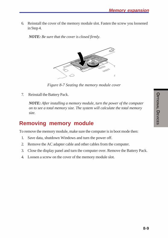
8-9
OP
TIO
NA
L DE
VIC
ES
Memory expansion
6. Reinstall the cover of the memory module slot. Fasten the screw you loosenedin Step 4.
NOTE: Be sure that the cover is closed firmly.
Figure 8-7 Seating the memory module cover
7. Reinstall the Battery Pack.
NOTE: After installing a memory module, turn the power of the computeron to see a total memory size. The system will calculate the total memorysize.
Removing memory moduleTo remove the memory module, make sure the computer is in boot mode then:
1. Save data, shutdown Windows and turn the power off.
2. Remove the AC adapter cable and other cables from the computer.
3. Close the display panel and turn the computer over. Remove the Battery Pack.
4. Loosen a screw on the cover of the memory module slot.
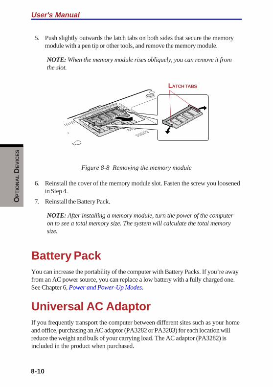
8-10
User's ManualO
PT
ION
AL D
EV
ICE
S
5. Push slightly outwards the latch tabs on both sides that secure the memorymodule with a pen tip or other tools, and remove the memory module.
NOTE: When the memory module rises obliquely, you can remove it fromthe slot.
Figure 8-8 Removing the memory module
6. Reinstall the cover of the memory module slot. Fasten the screw you loosenedin Step 4.
7. Reinstall the Battery Pack.
NOTE: After installing a memory module, turn the power of the computeron to see a total memory size. The system will calculate the total memorysize.
Battery PackYou can increase the portability of the computer with Battery Packs. If you’re awayfrom an AC power source, you can replace a low battery with a fully charged one.See Chapter 6, Power and Power-Up Modes.
Universal AC AdaptorIf you frequently transport the computer between different sites such as your homeand office, purchasing an AC adaptor (PA3282 or PA3283) for each location willreduce the weight and bulk of your carrying load. The AC adaptor (PA3282) isincluded in the product when purchased.
LATCH TABS

8-11
OP
TIO
NA
L DE
VIC
ES
Battery Charger
Battery ChargerThe battery charger (PA3091U) provides a convenient way to charge battery packswithout requiring the use your computer. The battery charger holds up to twoLithium-ion battery packs.
USB diskette KitThe 3 1/2" external diskette drive module can be connected to the USB port. Fordetails on connecting the 3 1/2" external diskette drive module, refer to Chapter 4,Operating Basics.
Tablet Multi DockIn addition to the ports available on the computer, the Tablet Multi Dock provides,audio line-out jack.
The Tablet Multi Dock connects directly to the docking interface on the bottom ofthe computer. The AC adaptor connects the Tablet Multi Dock to a power source.
CAUTION: The computer must be configured properly beforeconnecting to a LAN. Logging onto a LAN using the computer's defaultsettings could cause a malfunction in LAN operation. Check with yourLAN administrator regarding set-up procedures.
NOTE: You must connect the AC adaptor before you connect to a TabletMulti Dock.
The following ports and accessories are available on the Tablet Multi Dock.
❑ LAN jack (RJ45)
❑ External monitor port
❑ DC IN 15V socket
❑ Security lock slot
❑ Audio line-out jacks
❑ Universal Serial Bus (three) ports
❑ Slim Select Bay Slot
NOTE: When a Tablet Multi Dock is connected to the computer, removeall cables connected to the computer.

8-12
User's ManualO
PT
ION
AL D
EV
ICE
S
External monitorAn external analog monitor can be connected to the external monitor port on thecomputer. The computer supports VGA and Super VGA video modes. To connect amonitor, follow the steps below.
1. Turn the computer off.
2. Connect the monitor to the external monitor port.
3. Turn the monitor’s power on.
4. Turn the computer on.
When you turn on the power, the computer automatically recognizes the monitorand determines whether it is color or monochrome.
To change the display settings, press Fn + F5. If you disconnect the monitorbefore you turn the computer off, be sure to press Fn + F5 to switch to the internaldisplay. Refer to Chapter 5, The Keyboard, for details on using hot keys to changethe display setting.
Tablet PC Pen setUse it as a spare to your computer. Spare pen tip and draw-out tool are included.Refer to Chapter 6, Power and Power-Up Modes, for the detailed usage.
Reserve penSupplied pen uses a pen instead of Supplied pen at the time of loss or breakage.The pen is set inside the computer, which connects a battery pack. Refer to Chapter6, Power and Power-Up Modes, for the detailed usage.
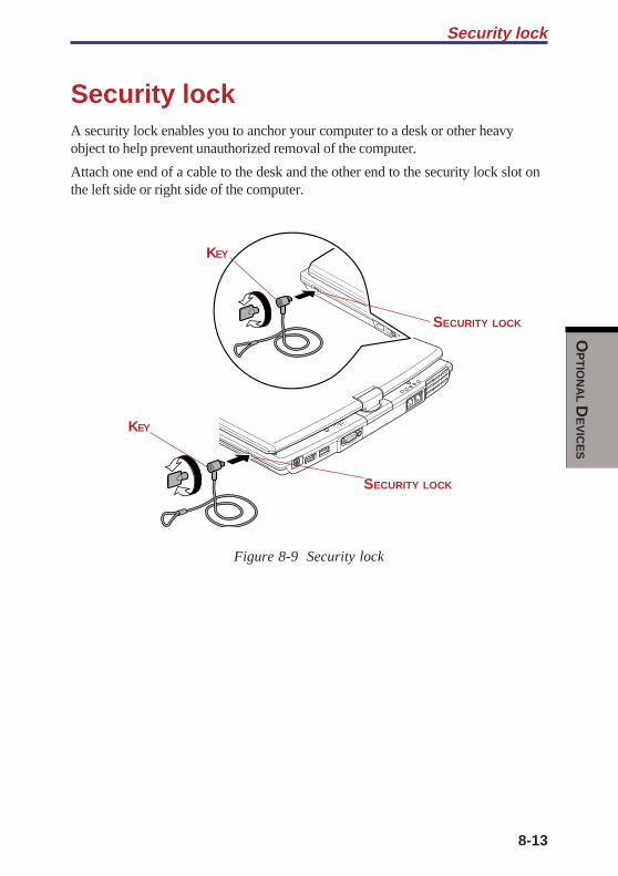
8-13
OP
TIO
NA
L DE
VIC
ES
Security lockA security lock enables you to anchor your computer to a desk or other heavyobject to help prevent unauthorized removal of the computer.
Attach one end of a cable to the desk and the other end to the security lock slot onthe left side or right side of the computer.
Figure 8-9 Security lock
Security lock
SECURITY LOCK
KEY
SECURITY LOCK
KEY

8-14
User's ManualO
PT
ION
AL D
EV
ICE
S

TR
OU
BL
ES
HO
OT
ING
Chapter 9
Troubleshooting
Problem solving process ................................................................... 9-1Preliminary checklist .......................................................................... 9-1Analyzing the problem ........................................................................ 9-2
Hardware and system checklist ........................................................ 9-3System start-up .................................................................................. 9-3Self test .............................................................................................. 9-4Power ................................................................................................. 9-4Password ........................................................................................... 9-7Keyboard ............................................................................................ 9-8LCD panel .......................................................................................... 9-8Hard disk drive .................................................................................... 9-9Diskette drive ...................................................................................... 9-9Infrared port ...................................................................................... 9-10Pointing device ................................................................................. 9-10PC card ............................................................................................ 9-13SD card ............................................................................................ 9-14Monitor ............................................................................................. 9-14Sound system .................................................................................. 9-15USB ................................................................................................. 9-15Memory expansion ........................................................................... 9-16Standby/Hibernation ......................................................................... 9-17Modem ............................................................................................. 9-17LAN .................................................................................................. 9-19Wireless LAN ................................................................................... 9-19Bluetooth .......................................................................................... 9-20Real Time Clock ............................................................................... 9-20
TOSHIBA support ............................................................................. 9-21Before you call ................................................................................. 9-21Where to write .................................................................................. 9-21

TR
OU
BL
ES
HO
OT
ING
9-1
TR
OU
BL
ES
HO
OT
ING
Chapter 9
TroubleshootingTOSHIBA designed the computer for durability. However, should problems occur,following the procedures in this chapter can help to determine the cause.
All readers should become familiar with this chapter. Knowing what might go wrongcan help prevent problems from occurring.
Problem solving processResolving problems will be much easier if you observe the following guidelines:
❑ Stop immediately when you recognize a problem exists. Further action mayresult in data loss or damage. You may destroy valuable problem-relatedinformation that can help solve the problem.
❑ Observe what is happening. Write down what the system is doing and whatactions you performed immediately before the problem occurred. If you have aprinter attached, print a copy of the screen using PrtSc.
The questions and procedures offered in this chapter are meant as a guide, they arenot definitive problem solving techniques. Many problems can be solved simply,but a few may require help from your dealer. If you find you need to consult yourdealer or others, be prepared to describe the problem in as much detail as possible.
Preliminary checklistConsider the simplest solution first. The items in this checklist are easy to fix andyet can cause what appears to be a serious problem.
❑ Make sure you turn on all peripheral devices before you turn on the computer.This includes your printer and any other external device you are using.
❑ Before you attach an external device, turn the computer off. When you turn thecomputer back on it recognizes the new device.
❑ Make sure all options are set properly in the setup program.
❑ Check all cables. Are they correctly and firmly attached? Loose cables cancause signal errors.
❑ Inspect all connecting cables for loose wires and all connectors for loose pins.
User's Manual
9-2
TR
OU
BL
ES
HO
OT
ING
❑ Check that your diskette is correctly inserted and that the diskette’s writeprotect tab is correctly set.
Make notes of your observations and keep them in a permanent error log. This willhelp you describe your problems to your dealer. If a problem recurs, the log will helpyou identify the problem faster.
Analyzing the problemSometimes the system gives clues that can help you identify why it is malfunction-ing. Keep the following questions in mind:
❑ Which part of the system is not operating properly: keyboard, diskette drives,hard disk drive, printer, display. Each device produces different symptoms.
❑ Is the operating system configuration set properly? Check the configurationoptions.
❑ What appears on the display screen? Does it display any messages or randomcharacters? Print a copy of the screen if you have a printer attached. Look upthe messages in the software and operating system documentation. Check thatall connecting cables are correctly and firmly attached. Loose cables can causeerroneous or intermittent signals.
❑ Do any icons light? Which ones? What color are they? Do they stay on orblink? Write down what you see.
❑ Do you hear any beeps? How many? Are they long or short? Are they highpitched or low? Is the computer making any unusual noises? Write down whatyou hear.
Record your observations so you can describe them to your dealer.
Software The problems may be caused by your software or diskette.If you cannot load a software package, the media (usuallya diskette) may be damaged or the program might becorrupted. Try loading another copy of the software.
If an error message appears while you are using a softwarepackage, check the software documentation. Thesedocuments usually include a problem solving section or asummary of error messages.
Next, check any error messages in the OS documentation.
Hardware If you cannot find a software problem, check yourhardware. First run through the items in the preliminarychecklist above. If you still cannot correct the problem, tryto identify the source. The next section provides checklistsfor individual components and peripherals.

9-3
TR
OU
BL
ES
HO
OT
ING
Hardware and system checklist
Hardware and system checklistThis section discusses problems caused by your computer’s hardware or attachedperipherals. Basic problems may occur in the following areas:
❑ System start-up ❑ SD card
❑ Self test ❑ Monitor
❑ Power ❑ Sound system
❑ Password ❑ USB
❑ Keyboard ❑ Memory expansion
❑ LCD panel ❑ Modem
❑ Hard disk drive ❑ Stand by / Hibernation
❑ Diskette drive ❑ LAN
❑ Infrared port ❑ Wireless LAN
❑ Pointing device ❑ Bluetooth
❑ PC card ❑ Real Time Clock (RTC)
System start-upWhen the computer does not start properly, check the following items:
❑ Self Test
❑ Power Sources
❑ Power-on Password
User's Manual
9-4
TR
OU
BL
ES
HO
OT
ING
Self testWhen the computer starts up, the self-test will be run automatically, and thefollowing will be displayed:
In Touch with Tomorrow
TOSHIBA
This message remains on the screen for a few seconds.
If the self test is successful, the computer tries to load the operating system,depending on how the Boot Priority is set in the HW Setup program.
If any of the following conditions are present, the self test failed:
❑ The computer stops and does not proceed to display information or messages.
❑ Random characters appear on the screen, and the system does not functionnormally.
❑ The screen displays an error message.
Turn off the computer and check all cable connections. If the test fails again,contact your dealer.
PowerWhen the computer is not plugged into an AC adaptor, the Battery Pack is theprimary power source. However, your computer has a number of other powerresources, including intelligent power supply and Real Time Clock battery. Theseresources are interrelated and any one could affect apparent power problems. Thissection provides check lists for AC adaptor and the main battery. If you cannotresolve a problem after following them, the cause could lie with another powerresource. In such case, contact your dealer.
9-5
TR
OU
BL
ES
HO
OT
ING
Hardware and system checklist
Overheating power down
If the computer’s internal temperature becomes too high, the computer will auto-matically enter Hibernation or Resume mode and shut down.
Problem Procedure
Computer shuts down Leave the computer off until the DC IN 15V andDC IN 15V indicator indicator stops blinking.blinks orange
NOTE: It is recommended to leave the computeroff until the its interior reaches room temperatureeven though the DC IN 15V indicator stopsblinking.
If the computer has reached room temperatureand still does not start, or if it starts but shutsdown quickly contact your dealer.
Computer shuts down Indicates a problem with the heat dispersaland its DC IN 15V system. Please contact your dealer.indicatoris flashing in green
AC power
If you have trouble turning on the computer with the AC adaptor connected, checkthe DC IN 15V indicator. Refer to Chapter 6, Power and Power-Up Modes for moreinformation.
Problem Procedure
AC adaptor doesn’t Check the connections. Make sure the cord ispower the computer firmly connected to the computer and a power(DC IN 15V indicator does outlet.not glow green)

User's Manual
9-6
TR
OU
BL
ES
HO
OT
ING
Check the condition of the cord and terminals. Ifthe cord is frayed or damaged, replace it. If theterminals are soiled, wipe them with cotton or aclean cloth.
If the AC adaptor still does not power the com-puter, contact your dealer.
Battery
If you suspect a problem with the battery, check the DC IN 15V indicator as well asthe Battery indicator. For information on indicators and battery operation seeChapter 6, Power and Power-Up Modes.
Problem Procedure
Battery doesn’t The battery may be discharged. Connect the ACpower the computer adaptor to charge the battery.
Battery doesn’t If the battery is completely discharged, it will notcharge when the AC begin charging immediately. Wait a few minutes.adaptor is attached(Battery indicator If the battery still does not charge, make sure does not glow in the outlet of the AC adaptor is supplying power.orange.) Test it by plugging in an appliance.
Check whether the battery is hot or cold to thetouch. If the battery is too hot or too cold, it willnot charge properly. Let it reach room tempera-ture.
Unplug the AC adaptor and remove the battery tomake sure the terminals are clean. If necessarywipe them with a soft dry cloth dipped in alcohol.
Connect the AC adaptor and replace the battery.Make sure it is securely seated.
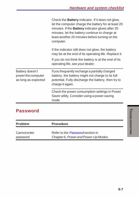
9-7
TR
OU
BL
ES
HO
OT
ING
Hardware and system checklist
Check the Battery indicator. If it does not glow,let the computer charge the battery for at least 20minutes. If the Battery indicator glows after 20minutes, let the battery continue to charge atleast another 20 minutes before turning on thecomputer.
If the indicator still does not glow, the batterymay be at the end of its operating life. Replace it.
If you do not think the battery is at the end of itsoperating life, see your dealer.
Battery doesn’t If you frequently recharge a partially chargedpower the computer battery, the battery might not charge to its fullas long as expected potential. Fully discharge the battery, then try to
charge it again.
Check the power consumption settings in PowerSaver utility. Consider using a power savingmode.
Password
Problem Procedure
Cannot enter Refer to the Password section inpassword Chapter 6, Power and Power-Up Modes.
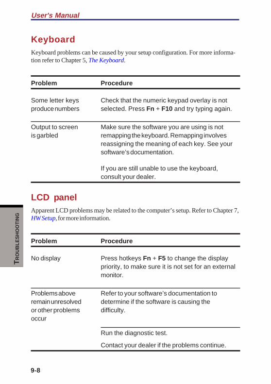
User's Manual
9-8
TR
OU
BL
ES
HO
OT
ING
KeyboardKeyboard problems can be caused by your setup configuration. For more informa-tion refer to Chapter 5, The Keyboard.
Problem Procedure
Some letter keys Check that the numeric keypad overlay is notproduce numbers selected. Press Fn + F10 and try typing again.
Output to screen Make sure the software you are using is notis garbled remapping the keyboard. Remapping involves
reassigning the meaning of each key. See yoursoftware’s documentation.
If you are still unable to use the keyboard,consult your dealer.
LCD panelApparent LCD problems may be related to the computer’s setup. Refer to Chapter 7,HW Setup, for more information.
Problem Procedure
No display Press hotkeys Fn + F5 to change the displaypriority, to make sure it is not set for an externalmonitor.
Problems above Refer to your software’s documentation toremain unresolved determine if the software is causing theor other problems difficulty.occur
Run the diagnostic test.
Contact your dealer if the problems continue.

9-9
TR
OU
BL
ES
HO
OT
ING
Hardware and system checklist
Hard disk drive
Problem Procedure
Computer does not Check if a diskette is in the diskette drive. If aboot from hard disk diskette is inserted, remove it and reboot.drive
There may be a problem with your operatingsystem files. Refer to your OS documentation.
Slow performance Your files may be fragmented. Run SCANDISKand defragmenter to check the condition of yourfiles and disk. Refer to your OS documentationor online HELP for information on runningSCANDISK and the defragmenter.
As a last resort, reformat the hard disk. Then,reload the operating system and other files.
If problems persist, contact your dealer.
Diskette driveFor more information, refer to Chapter 4, Operating Basics.
Problem Procedure
Drive does not There may be a faulty cable connection. Checkoperate the connection to the computer and to the drive.
Some programs run The software or hardware configuration may becorrectly but others causing a problem. Make sure the hardwaredo not configuration matches your software needs.
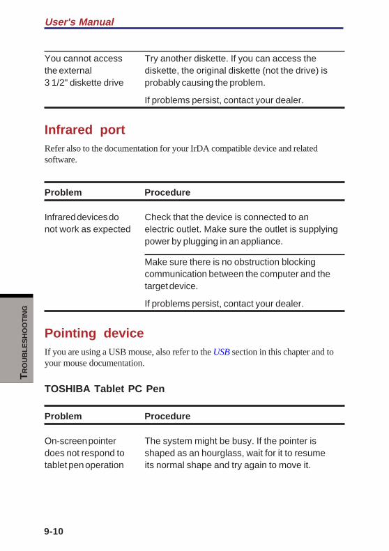
User's Manual
9-10
TR
OU
BL
ES
HO
OT
ING
You cannot access Try another diskette. If you can access thethe external diskette, the original diskette (not the drive) is3 1/2" diskette drive probably causing the problem.
If problems persist, contact your dealer.
Infrared portRefer also to the documentation for your IrDA compatible device and relatedsoftware.
Problem Procedure
Infrared devices do Check that the device is connected to annot work as expected electric outlet. Make sure the outlet is supplying
power by plugging in an appliance.
Make sure there is no obstruction blockingcommunication between the computer and thetarget device.
If problems persist, contact your dealer.
Pointing deviceIf you are using a USB mouse, also refer to the USB section in this chapter and toyour mouse documentation.
TOSHIBA Tablet PC Pen
Problem Procedure
On-screen pointer The system might be busy. If the pointer isdoes not respond to shaped as an hourglass, wait for it to resumetablet pen operation its normal shape and try again to move it.

9-11
TR
OU
BL
ES
HO
OT
ING
Hardware and system checklist
The tablet Pen might be set unable to use.
Press Fn + F9 keys to change Pen setting toenabled.
Tablet pen and Adjust the coordinate axis in the followingon-screen pointer do procedure.not move in the samemanner 1. Open the Control Panel and click Printer
and other Hardware.
2. Click the Tablet and Pen setting.
3. Select screen orientation with "Calibrate" in"Setting" tab.
4. Click "Calibrate" button.
5. Click the cross in "Calibrate the screen"and click "OK".
Unable input from Adjust the setting in the following procedure.tablet pen
1. Open the Control Panel and click Printerand other Hardware.
2. Click the Tablet and Pen setting.
3. Adjust setting of each item of "Pen options"
tab and click "OK".
Touch Pad
Problem Procedure
On-screen pointer The system might be busy. If the pointer isdoes not respond to shaped as an hourglass, wait for it to resumePad operation its normal shape and try again to move it.
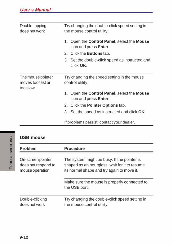
User's Manual
9-12
TR
OU
BL
ES
HO
OT
ING
Double-tapping Try changing the double-click speed setting indoes not work the mouse control utility.
1. Open the Control Panel, select the Mouseicon and press Enter.
2. Click the Buttons tab.
3. Set the double-click speed as instructed andclick OK.
The mouse pointer Try changing the speed setting in the mousemoves too fast or control utility.too slow
1. Open the Control Panel, select the Mouseicon and press Enter.
2. Click the Pointer Options tab.
3. Set the speed as instructed and click OK.
If problems persist, contact your dealer.
USB mouse
Problem Procedure
On-screen pointer The system might be busy. If the pointer isdoes not respond to shaped as an hourglass, wait for it to resumemouse operation its normal shape and try again to move it.
Make sure the mouse is properly connected tothe USB port.
Double-clicking Try changing the double-click speed setting indoes not work the mouse control utility.
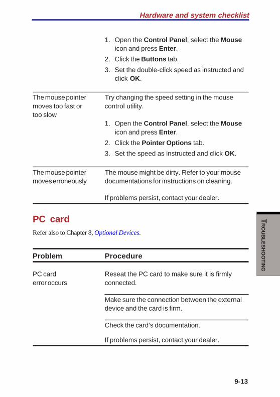
9-13
TR
OU
BL
ES
HO
OT
ING
Hardware and system checklist
1. Open the Control Panel, select the Mouseicon and press Enter.
2. Click the Buttons tab.
3. Set the double-click speed as instructed andclick OK.
The mouse pointer Try changing the speed setting in the mousemoves too fast or control utility.too slow
1. Open the Control Panel, select the Mouseicon and press Enter.
2. Click the Pointer Options tab.
3. Set the speed as instructed and click OK.
The mouse pointer The mouse might be dirty. Refer to your mousemoves erroneously documentations for instructions on cleaning.
If problems persist, contact your dealer.
PC cardRefer also to Chapter 8, Optional Devices.
Problem Procedure
PC card Reseat the PC card to make sure it is firmlyerror occurs connected.
Make sure the connection between the externaldevice and the card is firm.
Check the card’s documentation.
If problems persist, contact your dealer.
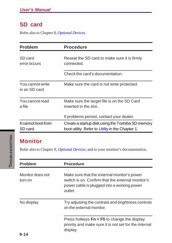
User's Manual
9-14
TR
OU
BL
ES
HO
OT
ING
SD cardRefer also to Chapter 8, Optional Devices.
Problem Procedure
SD card Reseat the SD card to make sure it is firmlyerror occurs connected.
Check the card’s documentation.
You cannot write Make sure the card is not write protected.in an SD card
You cannot read Make sure the target file is on the SD Carda file inserted in the slot.
If problems persist, contact your dealer.
It cannot boot from Create a startup disk using the Toshiba SD memorySD card. boot utility. Refer to Utility in the Chapter 1.
MonitorRefer also to Chapter 8, Optional Devices, and to your monitor’s documentation.
Problem Procedure
Monitor does not Make sure that the external monitor’s powerturn on switch is on. Confirm that the external monitor’s
power cable is plugged into a working poweroutlet.
No display Try adjusting the contrast and brightness controlson the external monitor.
Press hotkeys Fn + F5 to change the displaypriority and make sure it is not set for the internaldisplay.
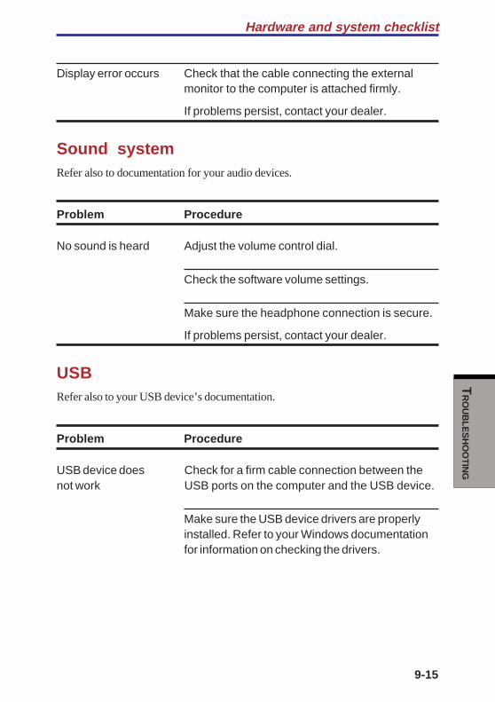
9-15
TR
OU
BL
ES
HO
OT
ING
Hardware and system checklist
Display error occurs Check that the cable connecting the externalmonitor to the computer is attached firmly.
If problems persist, contact your dealer.
Sound systemRefer also to documentation for your audio devices.
Problem Procedure
No sound is heard Adjust the volume control dial.
Check the software volume settings.
Make sure the headphone connection is secure.
If problems persist, contact your dealer.
USBRefer also to your USB device’s documentation.
Problem Procedure
USB device does Check for a firm cable connection between thenot work USB ports on the computer and the USB device.
Make sure the USB device drivers are properlyinstalled. Refer to your Windows documentationfor information on checking the drivers.
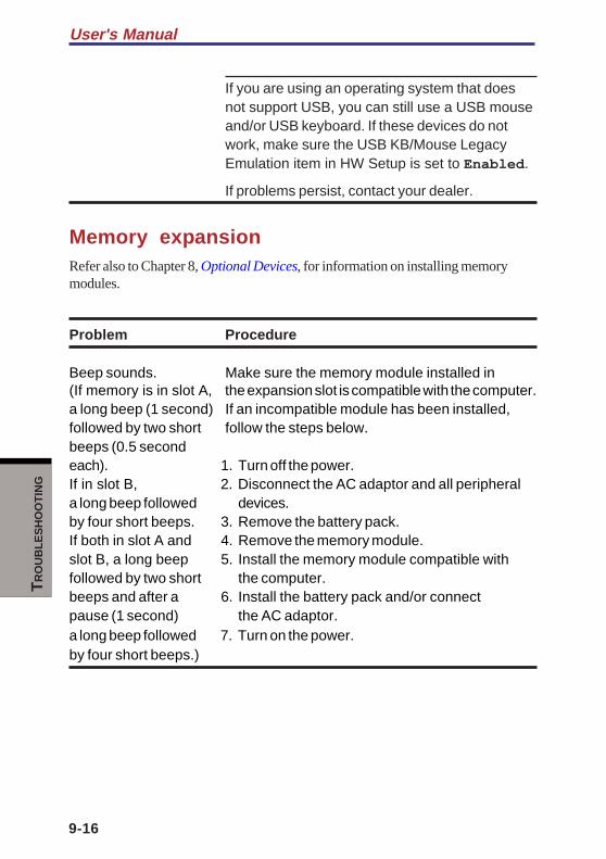
User's Manual
9-16
TR
OU
BL
ES
HO
OT
ING
If you are using an operating system that doesnot support USB, you can still use a USB mouseand/or USB keyboard. If these devices do notwork, make sure the USB KB/Mouse LegacyEmulation item in HW Setup is set to Enabled.
If problems persist, contact your dealer.
Memory expansionRefer also to Chapter 8, Optional Devices, for information on installing memorymodules.
Problem Procedure
Beep sounds. Make sure the memory module installed in(If memory is in slot A, the expansion slot is compatible with the computer.a long beep (1 second) If an incompatible module has been installed,followed by two short follow the steps below.beeps (0.5 secondeach). 1. Turn off the power.If in slot B, 2. Disconnect the AC adaptor and all peripherala long beep followed devices.by four short beeps. 3. Remove the battery pack.If both in slot A and 4. Remove the memory module.slot B, a long beep 5. Install the memory module compatible withfollowed by two short the computer.beeps and after a 6. Install the battery pack and/or connectpause (1 second) the AC adaptor.a long beep followed 7. Turn on the power.by four short beeps.)

9-17
TR
OU
BL
ES
HO
OT
ING
Hardware and system checklist
Standby/Hibernation
Problem Procedure
The system will Is Windows Media™ Player open? The systemnot enter might not enter Standby/Hibernation, if WindowsStandby/Hibernation Media Player is either playing a selection or
finished playing a selection. Close WindowsMedia Player before you select Standby/Hiberna-tion.
If problems persist, contact your dealer.
ModemRefer to the online help files for Appendix C and D.
Problem Procedure
Communication Make sure the computer’s internal modemsoftware can’t settings are correct. Refer to Modeminitialize modem Properties in the Control Panel.
You can hear a dial If the call is going through a PBX machine, maketone but can’t make sure the communication application’s tone diala call detection feature is disabled.
You can also use the ATX command. Refer toAppendix C, AT Commands.
You place a call, Make sure the settings are correct in yourbut a connection communications application.can’t be made
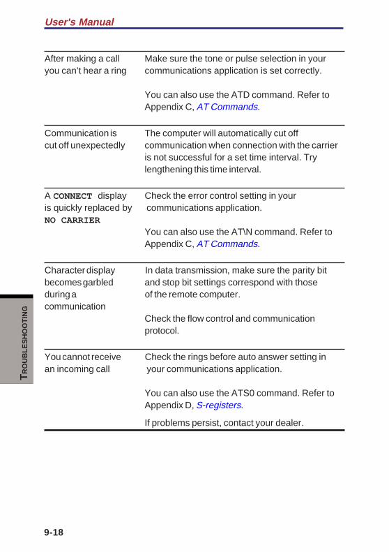
User's Manual
9-18
TR
OU
BL
ES
HO
OT
ING
After making a call Make sure the tone or pulse selection in youryou can’t hear a ring communications application is set correctly.
You can also use the ATD command. Refer toAppendix C, AT Commands.
Communication is The computer will automatically cut offcut off unexpectedly communication when connection with the carrier
is not successful for a set time interval. Trylengthening this time interval.
A CONNECT display Check the error control setting in youris quickly replaced by communications application.NO CARRIER
You can also use the AT\N command. Refer toAppendix C, AT Commands.
Character display In data transmission, make sure the parity bitbecomes garbled and stop bit settings correspond with thoseduring a of the remote computer.communication
Check the flow control and communicationprotocol.
You cannot receive Check the rings before auto answer setting inan incoming call your communications application.
You can also use the ATS0 command. Refer toAppendix D, S-registers.
If problems persist, contact your dealer.
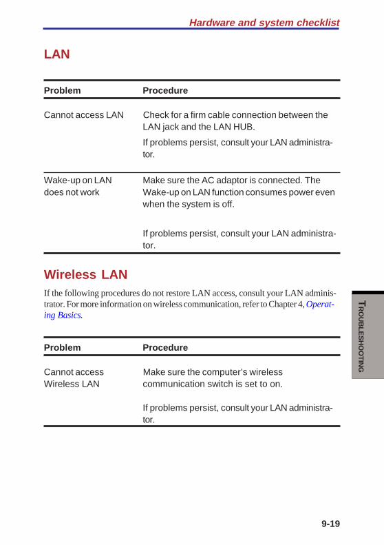
9-19
TR
OU
BL
ES
HO
OT
ING
Hardware and system checklist
LAN
Problem Procedure
Cannot access LAN Check for a firm cable connection between theLAN jack and the LAN HUB.
If problems persist, consult your LAN administra-tor.
Wake-up on LAN Make sure the AC adaptor is connected. Thedoes not work Wake-up on LAN function consumes power even
when the system is off.
If problems persist, consult your LAN administra-tor.
Wireless LANIf the following procedures do not restore LAN access, consult your LAN adminis-trator. For more information on wireless communication, refer to Chapter 4, Operat-ing Basics.
Problem Procedure
Cannot access Make sure the computer’s wirelessWireless LAN communication switch is set to on.
If problems persist, consult your LAN administra-tor.
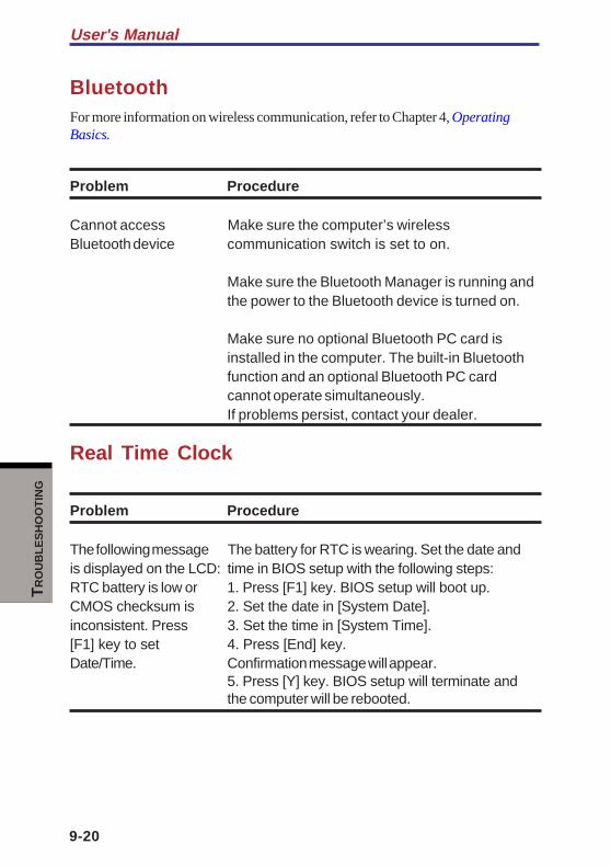
User's Manual
9-20
TR
OU
BL
ES
HO
OT
ING
BluetoothFor more information on wireless communication, refer to Chapter 4, OperatingBasics.
Problem Procedure
Cannot access Make sure the computer’s wirelessBluetooth device communication switch is set to on.
Make sure the Bluetooth Manager is running andthe power to the Bluetooth device is turned on.
Make sure no optional Bluetooth PC card isinstalled in the computer. The built-in Bluetoothfunction and an optional Bluetooth PC cardcannot operate simultaneously.If problems persist, contact your dealer.
Real Time Clock
Problem Procedure
The following message The battery for RTC is wearing. Set the date andis displayed on the LCD: time in BIOS setup with the following steps:RTC battery is low or 1. Press [F1] key. BIOS setup will boot up.CMOS checksum is 2. Set the date in [System Date].inconsistent. Press 3. Set the time in [System Time].[F1] key to set 4. Press [End] key.Date/Time. Confirmation message will appear.
5. Press [Y] key. BIOS setup will terminate andthe computer will be rebooted.
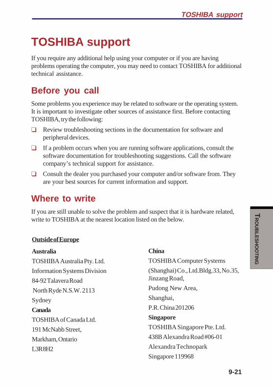
9-21
TR
OU
BL
ES
HO
OT
ING
TOSHIBA support
TOSHIBA supportIf you require any additional help using your computer or if you are havingproblems operating the computer, you may need to contact TOSHIBA for additionaltechnical assistance.
Before you callSome problems you experience may be related to software or the operating system.It is important to investigate other sources of assistance first. Before contactingTOSHIBA, try the following:
❑ Review troubleshooting sections in the documentation for software andperipheral devices.
❑ If a problem occurs when you are running software applications, consult thesoftware documentation for troubleshooting suggestions. Call the softwarecompany’s technical support for assistance.
❑ Consult the dealer you purchased your computer and/or software from. Theyare your best sources for current information and support.
Where to writeIf you are still unable to solve the problem and suspect that it is hardware related,write to TOSHIBA at the nearest location listed on the below.
Outside of Europe
Australia
TOSHIBA Australia Pty. Ltd.
Information Systems Division
84-92 Talavera Road
North Ryde N.S.W. 2113
Sydney
Canada
TOSHIBA of Canada Ltd.
191 McNabb Street,
Markham, Ontario
L3R 8H2
China
TOSHIBA Computer Systems
(Shanghai) Co., Ltd.Bldg.33, No.35,Jinzang Road,
Pudong New Area,
Shanghai,
P.R. China 201206
Singapore
TOSHIBA Singapore Pte. Ltd.
438B Alexandra Road #06-01
Alexandra Technopark
Singapore 119968
User's Manual
9-22
TR
OU
BL
ES
HO
OT
ING
United States of America
TOSHIBA America InformationSystems, Inc.
9740 Irvine Boulevard
Irvine, California 92618
USA
In Europe
Germany & AustriaTOSHIBA Europe (I.E.) GmbH
Geschäftsbereich,
Deutschland-Österreich
Hammfelddamm 8,
D-41460 Neuss, Germany
France
TOSHIBA Systèms France S.A.
7, Rue Ampère B.P. 131,
92804 Puteaux Cedex
Netherlands
TOSHIBA Information Systems,Benelux B.V.
Rivium Boulevard
41 2909 LK Capelle a/d IJssel
Spain
TOSHIBA Information Systems,ESPAÑA
Parque Empresarial San Fernando
Edificio Europa, la Planta,
Escalera A 28830 Madrid
United Kingdom
TOSHIBA Information Systems (U.K.)Ltd.
TOSHIBA Court
Weybridge Business Park
Addlestone Road
Weybridge, Surrey KT15 2UL
The Rest of Europe
TOSHIBA Europe (I.E.) GmbH
Geschäftsbereich,
Deutschland-Österreich
Hammfelddamm 8,
D-41460 Neuss, Germany

AP
PE
ND
IXE
S
Appendixes
Appendix ASpecifications ........................................................................... A-1
Appendix BDisplay Controller and Modes .............................................. B-1
Appendix CAT Commands ............................................................................. C-1
Appendix DS-registers .................................................................................... D-1
Appendix EV.90 ............................................................................................... E-1
Appendix FWireless LAN ................................................................................ F-1
Appendix GAC Power Cord and Connectors ................................................. G-1
Appendix HInternal Modem Guide ................................................................. H-1
Appendix IParts Numbers .............................................................................. I-1

AP
PE
ND
IXE
S
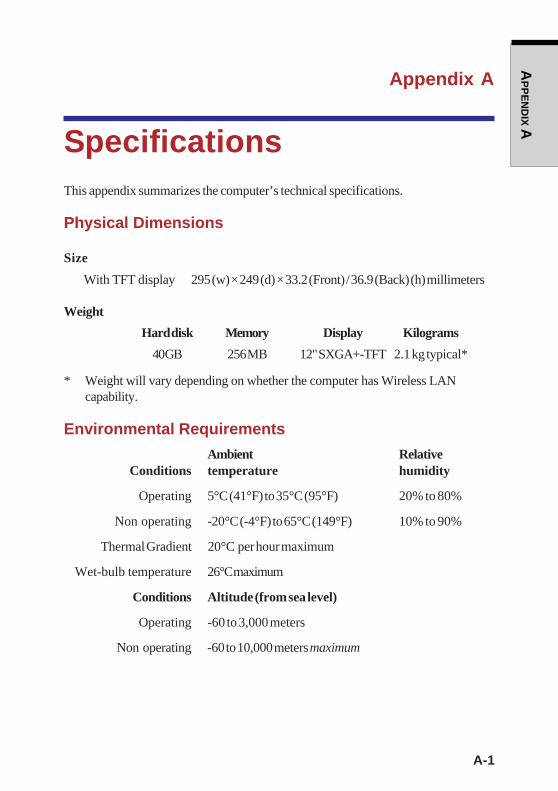
A-1
AP
PE
ND
IX A
Appendix A
SpecificationsThis appendix summarizes the computer’s technical specifications.
Physical Dimensions
Size
With TFT display 295 (w) × 249 (d) × 33.2 (Front) / 36.9 (Back) (h) millimeters
Weight
Hard disk Memory Display Kilograms
40 GB 256 MB 12" SXGA+-TFT 2.1 kg typical*
* Weight will vary depending on whether the computer has Wireless LANcapability.
Environmental Requirements
Ambient RelativeConditions temperature humidity
Operating 5°C (41°F) to 35°C (95°F) 20% to 80%
Non operating -20°C (-4°F) to 65°C (149°F) 10% to 90%
Thermal Gradient 20°C per hour maximum
Wet-bulb temperature 26°C maximum
Conditions Altitude (from sea level)
Operating -60 to 3,000 meters
Non operating -60 to 10,000 meters maximum
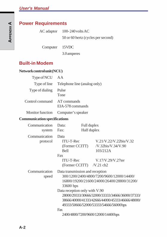
A-2
AP
PE
ND
IX A
User's Manual
Power Requirements
AC adaptor 100- 240 volts AC
50 or 60 hertz (cycles per second)
Computer 15 VDC
3.0 amperes
Built-in Modem
Network control unit (NCU)
Type of NCU AA
Type of line Telephone line (analog only)
Type of dialing PulseTone
Control command AT commandsEIA-578 commands
Monitor function Computer’s speaker
Communication specifications
Communication Data: Full duplex system Fax: Half duplex
Communication Data protocol ITU-T-Rec V.21/V.22/V.22bis/V.32
(Former CCITT) /V.32bis/V.34/V.90Bell 103/212A
FaxITU-T-Rec V.17/V.29/V.27ter(Former CCITT) /V.21 ch2
Communication Data transmission and reception speed 300/1200/2400/4800/7200/9600/12000/14400/
16800/19200/21600/24000/26400/28800/31200/33600 bps
Data reception only with V.9028000/29333/30666/32000/33333/34666/36000/37333/38666/40000/41333/42666/44000/45333/46666/48000/49333/50666/52000/53333/54666/56000 bps
Fax2400/4800/7200/9600/12000/14400 bps

A-3
AP
PE
ND
IX A
Error correcting MNP class 4 and ITU-T V.42
Data compression MNP class 5 and ITU-T V.42bis
Transmitting level-10 dBm
Receiving level -10 to -40 dBm
Input/output 600 ohms ±30% impedance
Power supply+3.3V (supplied by computer)
Appendix A

A-4
AP
PE
ND
IX A
User's Manual

B-1
AP
PE
ND
IX B
Appendix B
Display Controller andModes
Display controllerThe display controller interprets software commands into hardware commands thatturn particular pels on or off.
The controller is an advanced Video Graphics Array (VGA) that provides SuperVGA (SVGA) and Extended Graphics Array (XGA) support for the internal LCD andexternal monitors. The displays up to 1400 × 1050 (SXGA+). The controller alsosupports simultaneous display on the internal LCD and on an external monitor.
A high-resolution external monitor connected to the computer can display up to1600 horizontal and 1536 vertical pixels and up to 64K colors.
The display controller also controls the video mode, which uses industry standardrules to govern the screen resolution and the maximum number of colors that can bedisplayed on screen.
Software written for a given video mode will run on any computer that supports themode.
The computer’s display controller supports all VGA and SVGA modes, the mostwidely used industry standards.
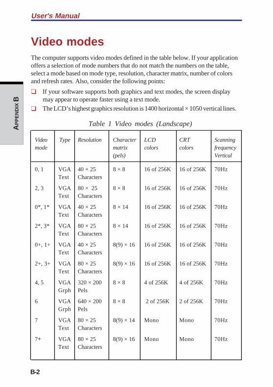
User's Manual
B-2
AP
PE
ND
IX B
Video modesThe computer supports video modes defined in the table below. If your applicationoffers a selection of mode numbers that do not match the numbers on the table,select a mode based on mode type, resolution, character matrix, number of colorsand refresh rates. Also, consider the following points:
❑ If your software supports both graphics and text modes, the screen displaymay appear to operate faster using a text mode.
❑ The LCD’s highest graphics resolution is 1400 horizontal × 1050 vertical lines.
Table 1 Video modes (Landscape)
Video Type Resolution Character LCD CRT Scanningmode matrix colors colors frequency
(pels) Vertical
0, 1 VGA 40 × 25 8 × 8 16 of 256K 16 of 256K 70HzText Characters
2, 3 VGA 80 × 25 8 × 8 16 of 256K 16 of 256K 70HzText Characters
0*, 1* VGA 40 × 25 8 × 14 16 of 256K 16 of 256K 70HzText Characters
2*, 3* VGA 80 × 25 8 × 14 16 of 256K 16 of 256K 70HzText Characters
0+, 1+ VGA 40 × 25 8(9) × 16 16 of 256K 16 of 256K 70HzText Characters
2+, 3+ VGA 80 × 25 8(9) × 16 16 of 256K 16 of 256K 70HzText Characters
4, 5 VGA 320 × 200 8 × 8 4 of 256K 4 of 256K 70HzGrph Pels
6 VGA 640 × 200 8 × 8 2 of 256K 2 of 256K 70HzGrph Pels
7 VGA 80 × 25 8(9) × 14 Mono Mono 70HzText Characters
7+ VGA 80 × 25 8(9) × 16 Mono Mono 70HzText Characters

B-3
AP
PE
ND
IX B
Table 1 Video modes (Landscape) continued
Video Type Resolution Character LCD CRT Scanning
mode matrix colors colors frequency(pels) Vertical
D VGA 320 × 200 8 × 8 16 of 256K 16 of 256K 70HzGrph Pels
E VGA 640 × 200 8 × 8 16 of 256K 16 of 256K 70HzGrph Pels
F VGA 640 × 350 8 × 14 Mono Mono 70HzGrph Pels
10 VGA 640 × 350 8 × 14 16 of 256K 16 of 256K 70HzGrph Pels
11 VGA 640 × 480 8 × 16 16 of 256K 16 of 256K 60HzGrph Pels
12 VGA 640 × 480 8 × 16 16 of 256K 16 of 256K 60HzGrph Pels
13 VGA 320 × 200 8 × 8 256 of 256K 256 of 256K 70HzGrph Pels
SVGA 640 × 480 256 of 256K 256 of 256K 60HzGrph Pels 75Hz
85Hz100Hz
SVGA 800 × 600 256 of 256K 256 of 256K 60HzGrph Pels 75Hz
85Hz100Hz
SVGA 1024 × 768 256 of 256K 256 of 256K 60HzGrph Pels 75Hz
85Hz100Hz
SVGA 1280 × 1024 256 of 256K 60HzGrph Pels 75Hz
85Hz100Hz
Appendix B
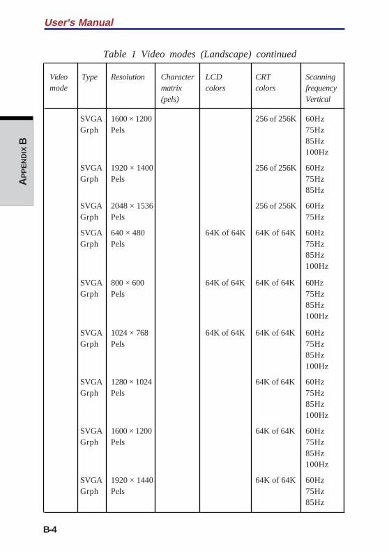
User's Manual
B-4
AP
PE
ND
IX B
Table 1 Video modes (Landscape) continued
Video Type Resolution Character LCD CRT Scanningmode matrix colors colors frequency
(pels) Vertical
SVGA 1600 × 1200 256 of 256K 60HzGrph Pels 75Hz
85Hz100Hz
SVGA 1920 × 1400 256 of 256K 60HzGrph Pels 75Hz
85Hz
SVGA 2048 × 1536 256 of 256K 60HzGrph Pels 75Hz
SVGA 640 × 480 64K of 64K 64K of 64K 60HzGrph Pels 75Hz
85Hz100Hz
SVGA 800 × 600 64K of 64K 64K of 64K 60HzGrph Pels 75Hz
85Hz100Hz
SVGA 1024 × 768 64K of 64K 64K of 64K 60HzGrph Pels 75Hz
85Hz100Hz
SVGA 1280 × 1024 64K of 64K 60HzGrph Pels 75Hz
85Hz100Hz
SVGA 1600 × 1200 64K of 64K 60HzGrph Pels 75Hz
85Hz100Hz
SVGA 1920 × 1440 64K of 64K 60HzGrph Pels 75Hz
85Hz
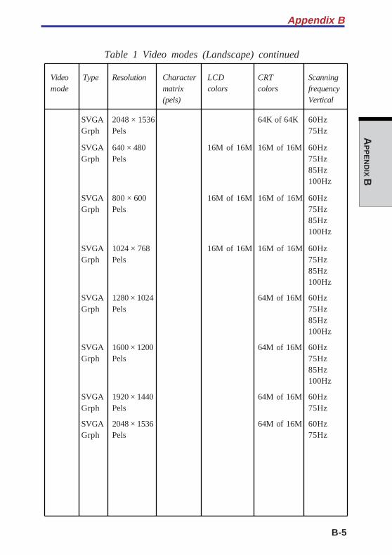
B-5
AP
PE
ND
IX B
Table 1 Video modes (Landscape) continued
Video Type Resolution Character LCD CRT Scanningmode matrix colors colors frequency
(pels) Vertical
SVGA 2048 × 1536 64K of 64K 60HzGrph Pels 75Hz
SVGA 640 × 480 16M of 16M 16M of 16M 60HzGrph Pels 75Hz
85Hz100Hz
SVGA 800 × 600 16M of 16M 16M of 16M 60HzGrph Pels 75Hz
85Hz100Hz
SVGA 1024 × 768 16M of 16M 16M of 16M 60HzGrph Pels 75Hz
85Hz100Hz
SVGA 1280 × 1024 64M of 16M 60HzGrph Pels 75Hz
85Hz100Hz
SVGA 1600 × 1200 64M of 16M 60HzGrph Pels 75Hz
85Hz100Hz
SVGA 1920 × 1440 64M of 16M 60HzGrph Pels 75Hz
SVGA 2048 × 1536 64M of 16M 60HzGrph Pels 75Hz
Appendix B
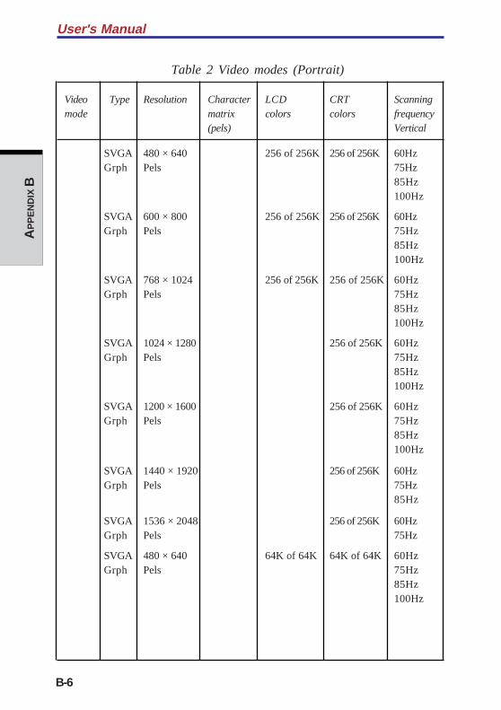
User's Manual
B-6
AP
PE
ND
IX B
Table 2 Video modes (Portrait)
Video Type Resolution Character LCD CRT Scanningmode matrix colors colors frequency
(pels) Vertical
SVGA 480 × 640 256 of 256K 256 of 256K 60HzGrph Pels 75Hz
85Hz100Hz
SVGA 600 × 800 256 of 256K 256 of 256K 60HzGrph Pels 75Hz
85Hz100Hz
SVGA 768 × 1024 256 of 256K 256 of 256K 60HzGrph Pels 75Hz
85Hz100Hz
SVGA 1024 × 1280 256 of 256K 60HzGrph Pels 75Hz
85Hz100Hz
SVGA 1200 × 1600 256 of 256K 60HzGrph Pels 75Hz
85Hz100Hz
SVGA 1440 × 1920 256 of 256K 60HzGrph Pels 75Hz
85Hz
SVGA 1536 × 2048 256 of 256K 60HzGrph Pels 75Hz
SVGA 480 × 640 64K of 64K 64K of 64K 60HzGrph Pels 75Hz
85Hz100Hz
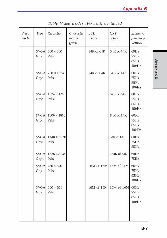
B-7
AP
PE
ND
IX B
Table Video modes (Portrait) continued
Video Type Resolution Character LCD CRT Scanningmode matrix colors colors frequency
(pels) Vertical
SVGA 600 × 800 64K of 64K 64K of 64K 60HzGrph Pels 75Hz
85Hz100Hz
SVGA 768 × 1024 64K of 64K 64K of 64K 60HzGrph Pels 75Hz
85Hz100Hz
SVGA 1024 × 1280 64K of 64K 60HzGrph Pels 75Hz
85Hz100Hz
SVGA 1200 × 1600 64K of 64K 60HzGrph Pels 75Hz
85Hz100Hz
SVGA 1440 × 1920 64K of 64K 60HzGrph Pels 75Hz
85Hz
SVGA 1536 ×2048 264K of 64K 60HzGrph Pels 75Hz
SVGA 480 × 640 16M of 16M 16M of 16M 60HzGrph Pels 75Hz
85Hz100Hz
SVGA 600 × 800 16M of 16M 16M of 16M 60HzGrph Pels 75Hz
85Hz100Hz
Appendix B
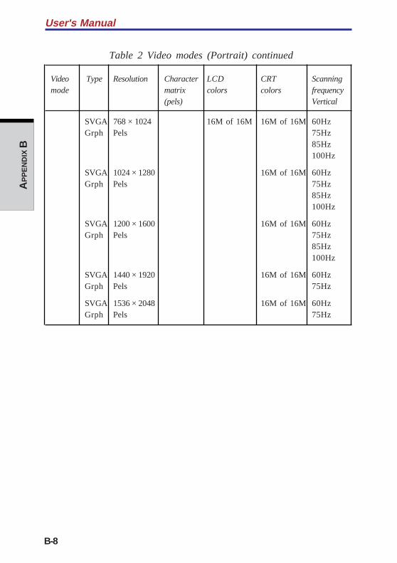
User's Manual
B-8
AP
PE
ND
IX B
Table 2 Video modes (Portrait) continued
Video Type Resolution Character LCD CRT Scanningmode matrix colors colors frequency
(pels) Vertical
SVGA 768 × 1024 16M of 16M 16M of 16M 60HzGrph Pels 75Hz
85Hz100Hz
SVGA 1024 × 1280 16M of 16M 60HzGrph Pels 75Hz
85Hz100Hz
SVGA 1200 × 1600 16M of 16M 60HzGrph Pels 75Hz
85Hz100Hz
SVGA 1440 × 1920 16M of 16M 60HzGrph Pels 75Hz
SVGA 1536 × 2048 16M of 16M 60HzGrph Pels 75Hz
C-1
AP
PE
ND
IX C
Appendix C
AT CommandsIn most cases, you will not need to type AT commands manually. However,there might be some occasions when you will need to do so.
This chapter describes AT commands for data mode. Fax and voice commandsare taken care of by application software.
The format for entering AT commands is:
ATXn
where X is the AT command, and n is the specific value for that command. Afteryou type in the command press Enter.
Any command issued is acknowledged with a response in either text or numericvalues known as result codes.
All commands and command-values accepted by the modem are described inthis section; any entry other than those listed results in an error.
+++ Escape sequence
The escape sequence allows the modem to exit data mode and enteron-line command mode. While in on-line command mode, you cancommunicate directly to your modem using AT commands. Once youfinish, you can return to data mode using the ATO command.
A pause, the length of which is set by Escape Guard Time (S12), mustbe completed after an escape sequence is entered, This pause preventsthe modem from interpreting the escape sequence as data.
The value of the escape sequence character may be changed usingregister S2.
A/ Repeat last command
This command repeats the last command string entered. Do notprecede this command with an AT prefix or conclude it by pressingEnter.
User's Manual
C-2
AP
PE
ND
IX C
A Answer command
This command instructs the modem to go off-hook and answer anincoming call.
Bn Communication standard setting
This command determines the communication standard CCITT or Bell.
B0 Selects CCITT V.22 mode when the modem is at 1200 bps.
B1 Selects Bell 212A when the modem is at 1200 bps (default).
B15 Selects V.21 when the modem is at 300 bps.
B16 Selects Bell 103J when the modem is at 300 bps (default).
Result Codes:
OK n=0,1,15,16
ERROR Otherwise
Dn Dial
This command instructs the modem to dial a telephone number. Enter n(the telephone number and any modifiers) after the ATD command.
Any digit or symbol (0-9, *, #, A, B, C, D) may be dialed as touch-tonedigits. Characters such as spaces, hyphens, and parentheses do notcount. They are ignored by the modem, but you may want to includethem to make the number and modifiers easier to read.
The following may be used as phone number modifiers:
P Pulse dialing.
T Touch-tone dialing (default).
, Pause during dialing. Pause for time specified in Register S8before processing the next character in the dial string.
W Wait for dial tone. Modem waits for a second dial tone beforeprocessing the dial string.
@ Wait for quiet answer. Wait for five seconds of silence afterdialing the number. If silence is not detected, the modemsends a NO ANSWER result code back to the caller.
! Hook flash. Causes the modem to go on-hook for 0.5 secondsand then return to off-hook.
C-3
AP
PE
ND
IX C
; Return to command mode. Causes the modem to return tocommand mode after dialing a number, without disconnectingthe call.
S=n Dial a telephone number previously stored using the &Zn=Xcommand (See &Zn=X command for more information). Therange is 0-3.
En Echo command
This command controls whether or not the characters entered fromyour computer keyboard are displayed on your monitor (echoed) whilethe modem is in command mode.
E0 Disables echo to the computer.
E1 Enables echo to the computer (default).
Result Codes:
OK n=0,1
ERROR Otherwise
Hn Hook control
This command instructs the modem to go on-hook to disconnect a call,or off-hook to make the phone line busy.
H0 Modem goes on-hook (default).
H1 Modem goes off-hook.
Result Codes:
OK n=0,1
ERROR Otherwise
In Request ID information
This command displays product information about the modem.
I0 Returns modem identity string and driver version number.
I3 Same as I0.
I9 Returns region ID in English.
Result Codes:
OK n=0,3,9
ERROR Otherwise
Appendix C
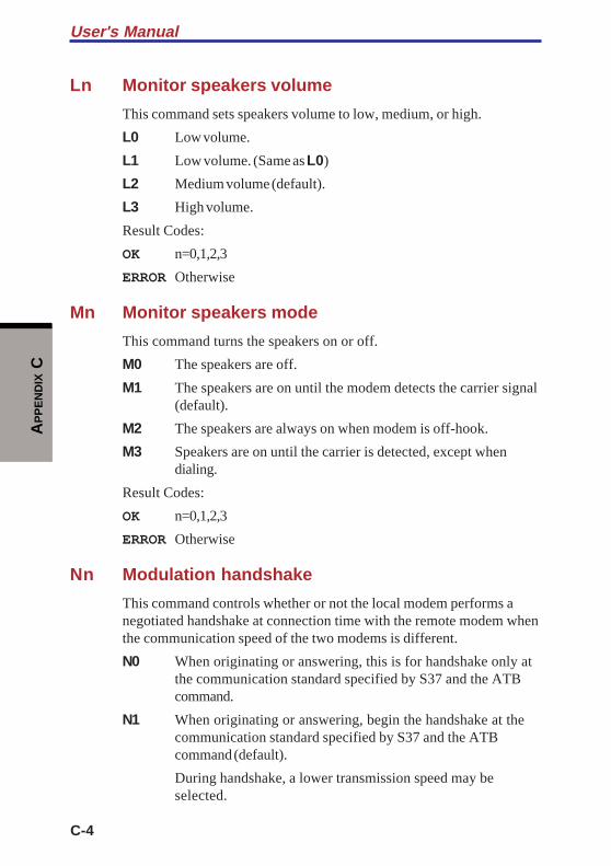
User's Manual
C-4
AP
PE
ND
IX C
Ln Monitor speakers volume
This command sets speakers volume to low, medium, or high.
L0 Low volume.
L1 Low volume. (Same as L0)
L2 Medium volume (default).
L3 High volume.
Result Codes:
OK n=0,1,2,3
ERROR Otherwise
Mn Monitor speakers mode
This command turns the speakers on or off.
M0 The speakers are off.
M1 The speakers are on until the modem detects the carrier signal(default).
M2 The speakers are always on when modem is off-hook.
M3 Speakers are on until the carrier is detected, except whendialing.
Result Codes:
OK n=0,1,2,3
ERROR Otherwise
Nn Modulation handshake
This command controls whether or not the local modem performs anegotiated handshake at connection time with the remote modem whenthe communication speed of the two modems is different.
N0 When originating or answering, this is for handshake only atthe communication standard specified by S37 and the ATBcommand.
N1 When originating or answering, begin the handshake at thecommunication standard specified by S37 and the ATBcommand (default).
During handshake, a lower transmission speed may beselected.
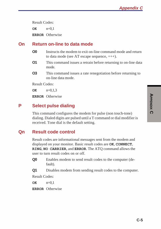
C-5
AP
PE
ND
IX C
Result Codes:
OK n=0,1
ERROR Otherwise
On Return on-line to data mode
O0 Instructs the modem to exit on-line command mode and returnto data mode (see AT escape sequence, +++).
O1 This command issues a retrain before returning to on-line datamode.
O3 This command issues a rate renegotiation before returning toon-line data mode.
Result Codes:
OK n=0,1,3
ERROR Otherwise
P Select pulse dialing
This command configures the modem for pulse (non touch-tone)dialing. Dialed digits are pulsed until a T command or dial modifier isreceived. Tone dial is the default setting.
Qn Result code control
Result codes are informational messages sent from the modem anddisplayed on your monitor. Basic result codes are OK, CONNECT,RING, NO CARRIER, and ERROR. The ATQ command allows theuser to turn result codes on or off.
Q0 Enables modem to send result codes to the computer (de-fault).
Q1 Disables modem from sending result codes to the computer.
Result Codes:
OK n=0,1
ERROR Otherwise
Appendix C
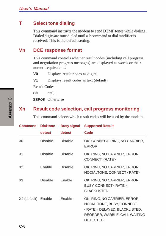
User's Manual
C-6
AP
PE
ND
IX C
T Select tone dialing
This command instructs the modem to send DTMF tones while dialing.Dialed digits are tone dialed until a P command or dial modifier isreceived. This is the default setting.
Vn DCE response format
This command controls whether result codes (including call progressand negotiation progress messages) are displayed as words or theirnumeric equivalents.
V0 Displays result codes as digits.
V1 Displays result codes as text (default).
Result Codes:
OK n=0,1
ERROR Otherwise
Xn Result code selection, call progress monitoring
This command selects which result codes will be used by the modem.
Command Dial tone Busy signal Supported Result
detect detect Code
X0 Disable Disable OK, CONNECT, RING, NO CARRIER,
ERROR
X1 Disable Disable OK, RING, NO CARRIER, ERROR,
CONNECT <RATE>
X2 Enable Disable OK, RING, NO CARRIER, ERROR,
NODIALTONE, CONNECT <RATE>
X3 Disable Enable OK, RING, NO CARRIER, ERROR,
BUSY, CONNECT <RATE>,
BLACKLISTED
X4 (default) Enable Enable OK, RING, NO CARRIER, ERROR,
NODIALTONE, BUSY, CONNECT
<RATE>, DELAYED, BLACKLISTED,
REORDER, WARBLE, CALL WAITING
DETECTED

C-7
AP
PE
ND
IX C
X5 Enable Enable OK, RING, NO CARRIER, ERROR,
NODIALTONE, BUSY, CONNECT
<RATE>, RRING, NO BONGTONE,
DELAYED, BLACKLISTED, REORDER,
WARBLE, CALL WAITING DETECTED
Dial tone detect
Disabled: The modem dials a call regardless of whether it detects adial tone.
Enabled: The modem dials only upon detection of a dial tone, anddisconnects the call if the dial tone is not detected within10 seconds.
Busy tone detect
Disabled: The modem ignores any busy tones it receives.
Enabled: The modem monitors for busy tones.
Result Codes:
OK n=0,1,2,3,4,5
ERROR Otherwise
Zn Recall stored profile
The modem performs a soft reset and restores (recalls) the configura-tion profile according to the parameter supplied. If no parameter isspecified, zero is assumed. Either Z0 or Z1 restores the profile.
Result Codes:
OK n=0,1
ERROR Otherwise
&Cn Data Carrier Detect (DCD) control
Data Carrier Detect is a signal from the modem to the computerindicating that a carrier signal is being received from a remote modem.DCD normally turns off when the modem no longer detects the carriersignal.
Appendix C
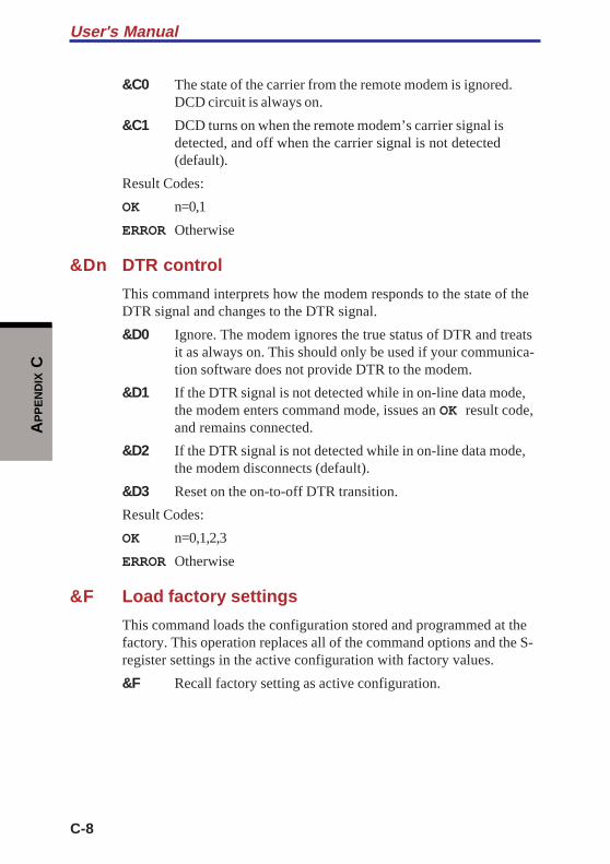
User's Manual
C-8
AP
PE
ND
IX C
&C0 The state of the carrier from the remote modem is ignored.DCD circuit is always on.
&C1 DCD turns on when the remote modem’s carrier signal isdetected, and off when the carrier signal is not detected(default).
Result Codes:
OK n=0,1
ERROR Otherwise
&Dn DTR control
This command interprets how the modem responds to the state of theDTR signal and changes to the DTR signal.
&D0 Ignore. The modem ignores the true status of DTR and treatsit as always on. This should only be used if your communica-tion software does not provide DTR to the modem.
&D1 If the DTR signal is not detected while in on-line data mode,the modem enters command mode, issues an OK result code,and remains connected.
&D2 If the DTR signal is not detected while in on-line data mode,the modem disconnects (default).
&D3 Reset on the on-to-off DTR transition.
Result Codes:
OK n=0,1,2,3
ERROR Otherwise
&F Load factory settings
This command loads the configuration stored and programmed at thefactory. This operation replaces all of the command options and the S-register settings in the active configuration with factory values.
&F Recall factory setting as active configuration.

C-9
AP
PE
ND
IX C
&Gn V.22bis guard tone control
This command determines which guard tone, if any, to transmit whiletransmitting in the high band (answer mode). This command is onlyused in V.22 and V.22bis mode. This option is not used in NorthAmerica and is for international use only.
&G0 Guard tone disabled (default).
&G1 Sets guard tone to 550 Hz.
&G2 Sets guard tone to 1800 Hz.
Result Codes:
OK n=0,1,2
ERROR Otherwise
&Kn Local flow control selection
&K0 Disable flow control.
&K3 Enable CTS/RTS flow control (default).
&K4 Enable XON/XOFF flow control.
Result Codes:
OK n=0,3,4
ERROR Otherwise
&Pn Select Pulse Dial Make/Break Ratio (WW)
&P0 Selects 39% - 61% make/break ratio at 10 pulses per second.
&P1 Selects 33% - 67% make/break ratio at 10 pulses per second.
&P2 Selects 33% - 67% make/break ratio at 20 pulses per second.
Result Codes:
OK n=0,1,2
ERROR Otherwise
&Tn Self-test commands
These tests can help to isolate problems if you experience periodicdata loss or random errors.
Appendix C
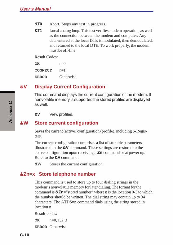
User's Manual
C-10
AP
PE
ND
IX C
&T0 Abort. Stops any test in progress.
&T1 Local analog loop. This test verifies modem operation, as wellas the connection between the modem and computer. Anydata entered at the local DTE is modulated, then demodulated,and returned to the local DTE. To work properly, the modemmust be off-line.
Result Codes:
OK n=0
CONNECT n=1
ERROR Otherwise
&V Display Current Configuration
This command displays the current configuration of the modem. Ifnonvolatile memory is supported the stored profiles are displayedas well.
&V View profiles.
&W Store current configuration
Saves the current (active) configuration (profile), including S-Regis-ters.
The current configuration comprises a list of storable parametersillustrated in the &V command. These settings are restored to theactive configuration upon receiving a Zn command or at power up.Refer to the &V command.
&W Stores the current configuration.
&Zn=x Store telephone number
This command is used to store up to four dialing strings in themodem’s nonvolatile memory for later dialing. The format for thecommand is &Zn=“stored number” where n is the location 0-3 to whichthe number should be written. The dial string may contain up to 34characters. The ATDS=n command dials using the string stored inlocation n.
Result codes:
OK n=0, 1, 2, 3
ERROR Otherwise
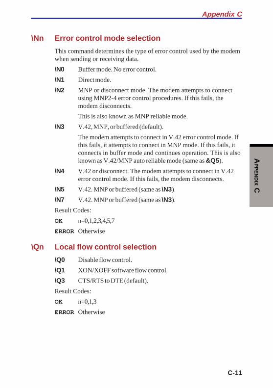
C-11
AP
PE
ND
IX C
\Nn Error control mode selection
This command determines the type of error control used by the modemwhen sending or receiving data.
\N0 Buffer mode. No error control.
\N1 Direct mode.
\N2 MNP or disconnect mode. The modem attempts to connectusing MNP2-4 error control procedures. If this fails, themodem disconnects.
This is also known as MNP reliable mode.
\N3 V.42, MNP, or buffered (default).
The modem attempts to connect in V.42 error control mode. Ifthis fails, it attempts to connect in MNP mode. If this fails, itconnects in buffer mode and continues operation. This is alsoknown as V.42/MNP auto reliable mode (same as &Q5).
\N4 V.42 or disconnect. The modem attempts to connect in V.42error control mode. If this fails, the modem disconnects.
\N5 V.42. MNP or buffered (same as \N3).
\N7 V.42. MNP or buffered (same as \N3).
Result Codes:
OK n=0,1,2,3,4,5,7
ERROR Otherwise
\Qn Local flow control selection
\Q0 Disable flow control.
\Q1 XON/XOFF software flow control.
\Q3 CTS/RTS to DTE (default).
Result Codes:
OK n=0,1,3
ERROR Otherwise
Appendix C

User's Manual
C-12
AP
PE
ND
IX C
\Vn Protocol result code
\V0 Disable protocol result code appended to DCE speed.
\V1 Enable protocol result code appended to DCE speed (default).
Result Codes:
OK n=0,1
ERROR Otherwise
%B View numbers in blacklist
If blacklisting is in effect, this command displays the numbers forwhich the last call attempted in the past two hours failed. The ERRORresult code appears in regions that do not require blacklisting.
%Cn Data compression control
This command determines the operation of V.42bis and MNP class 5data compression. On-line changes do not take effect until a discon-nect occurs first.
%C0 V.42bis/MNP 5 disabled. No data compression.
%C3 V.42bis/MNP 5 enabled. Data compression enabled (default).
Result Codes:
OK n=0,3
ERROR Otherwise
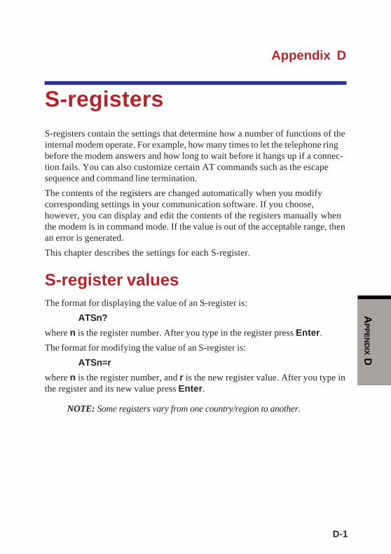
D-1
AP
PE
ND
IX D
Appendix D
S-registersS-registers contain the settings that determine how a number of functions of theinternal modem operate. For example, how many times to let the telephone ringbefore the modem answers and how long to wait before it hangs up if a connec-tion fails. You can also customize certain AT commands such as the escapesequence and command line termination.
The contents of the registers are changed automatically when you modifycorresponding settings in your communication software. If you choose,however, you can display and edit the contents of the registers manually whenthe modem is in command mode. If the value is out of the acceptable range, thenan error is generated.
This chapter describes the settings for each S-register.
S-register valuesThe format for displaying the value of an S-register is:
ATSn?
where n is the register number. After you type in the register press Enter.
The format for modifying the value of an S-register is:
ATSn=r
where n is the register number, and r is the new register value. After you type inthe register and its new value press Enter.
NOTE: Some registers vary from one country/region to another.

User's Manual
D-2
AP
PE
ND
IX D
S0 Auto answer ring number
This register determines the number of rings the modem will countbefore automatically answering a call. Enter 0 (zero) if you do not wantthe modem to automatically answer at all. When disabled, the modemcan only answer with an ATA command.
Range: 0-255
Default: 0
Units: rings
S1 Ring counter
This register is read only. The value of S1 is incremented with eachring. If no ring occurs over a six-second interval, this register iscleared.
Range: 0-225
Default: 0
Units: rings
S2 AT escape character (user defined)
This register determines the ASCII values used for an escape se-quence. The default is the + character. The escape sequence allows themodem to exit data mode and enter command mode when on-line.Values greater than 127 disable the escape sequence.
Range: 0-255, ASCII decimal
Default: 43
Units: ASCII
S3 Command line termination character
(user defined)
This register determines the ASCII values as the carriage returncharacter. This character is used to end command lines and resultcodes.
Range: 0-127, ASCII decimal
Default: 13 (carriage return)
Units: ASCII

D-3
AP
PE
ND
IX D
S4 Response formatting character (user defined)
This register determines the ASCII value used as the line feed charac-ter. The modem uses a line feed character in command mode when itresponds to the computer.
Range: 0-127, ASCII decimal
Default: 10 (line feed)
Units: ASCII
S5 Command line editing character (user defined)
This register sets the character recognized as a backspace and pertainsto asynchronous only. The modem will not recognize the backspacecharacter if it is set to a value that is greater than 32 ASCII. Thischaracter can be used to edit a command line. When the echo com-mand is enabled, the modem echoes back to the local DTE the back-space character, an ASCII space character, and a second backspacecharacter. This means a total of three characters are transmitted eachtime the modem processes the backspace character.
Range: 0-127, ASCII decimal
Default: 8 (backspace)
Units: ASCII
S6 Wait before dialing
This register sets the length of time, in seconds, that the modem mustwait (pause) after going off-hook before dialing the first digit of thetelephone number. The modem always pauses for a minimum of twoseconds, even if the value of S6 is less that two seconds. The wait fordial tone call progress feature (W dial modifier in the dial string) willoverride the value in register S6. This operation, however, may beaffected by some ATX options according to country/region restric-tions. In some countries/regions, S6 will set dial tone detect time.
Range: 3-255
Default: 3
Units: seconds
Appendix D
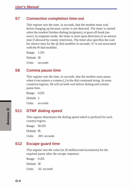
User's Manual
D-4
AP
PE
ND
IX D
S7 Connection completion time-out
This register sets the time, in seconds, that the modem must waitbefore hanging up because carrier is not detected. The timer is startedwhen the modem finishes dialing (originate), or goes off-hook (an-swer). In originate mode, the timer is reset upon detection of an answertone if allowed by county restriction. The timer also specifies the waitfor silence time for the @ dial modifier in seconds. S7 is not associatedwith the W dial modifier.
Range: 1-255
Default: 50
Units: seconds
S8 Comma pause time
This register sets the time, in seconds, that the modem must pausewhen it encounters a comma (,) in the dial command string. In somecountries/regions, S8 will set both wait before dialing and commapause time.
Range: 0-255
Default: 2
Units: seconds
S11 DTMF dialing speed
This register determines the dialing speed which is prefixed for eachcountry/region.
Range: 50-255
Default: 95
Units: .001 seconds
S12 Escape guard time
This register sets the value (in 20 millisecond increments) for therequired pause after the escape sequence.
Range: 0-255
Default: 50
Units: .02 seconds
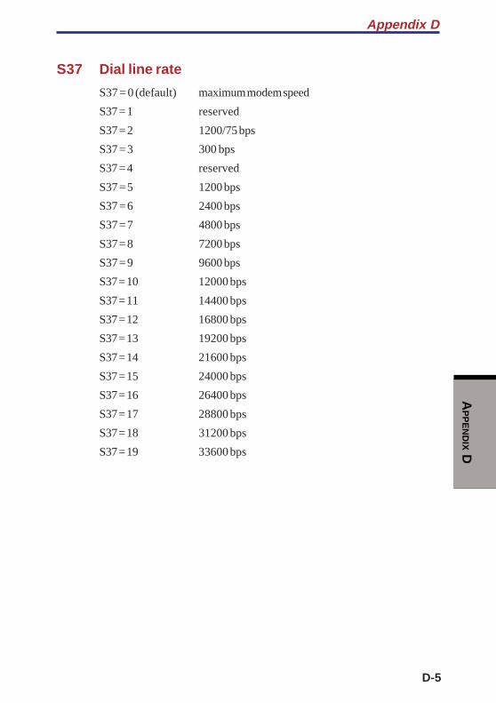
D-5
AP
PE
ND
IX D
S37 Dial line rate
S37 = 0 (default) maximum modem speed
S37 = 1 reserved
S37 = 2 1200/75 bps
S37 = 3 300 bps
S37 = 4 reserved
S37 = 5 1200 bps
S37 = 6 2400 bps
S37 = 7 4800 bps
S37 = 8 7200 bps
S37 = 9 9600 bps
S37 = 10 12000 bps
S37 = 11 14400 bps
S37 = 12 16800 bps
S37 = 13 19200 bps
S37 = 14 21600 bps
S37 = 15 24000 bps
S37 = 16 26400 bps
S37 = 17 28800 bps
S37 = 18 31200 bps
S37 = 19 33600 bps
Appendix D

User's Manual
D-6
AP
PE
ND
IX D
AT command set result codesThe following table shows the result codes.
The result code summary
Result Code Numeric Description
OK 0 Command executed
CONNECT 1 Modem connected to line
RING 2 A ring signal has been detected
NO CARRIER 3 Modem lost carrier signal, or doesnot detect carrier signal, or doesnot detect answer tone
ERROR 4 Invalid command
CONNECT 1200 EC*1 5 Connection at 1200 bps
NO DIAL TONE 6 No dial tone detected
BUSY 7 Busy signal detected
NO ANSWER 8 No quiet answer
CONNECT 2400 EC*1 10 Connection at 2400 bps
CONNECT 4800 EC*1 11 Connection at 4800 bps
CONNECT 9600 EC*1 12 Connection at 9600 bps
CONNECT 14400 EC*1 13 Connection at 14400 bps
CONNECT 19200 EC*1 14 Connection at 19200 bps
CONNECT 7200 EC*1 24 Connection at 7200 bps
CONNECT 12000 EC*1 25 Connection at 12000 bps
CONNECT 16800 EC*1 86 Connection at 16800 bps
CONNECT 300 EC*1 40 Connection at 300 bps
CONNECT 21600 EC*1 55 Connection at 21600 bps
CONNECT 24000 EC*1 56 Connection at 24000 bps
CONNECT 26400 EC*1 57 Connection at 26400 bps
CONNECT 28800 EC*1 58 Connection at 28800 bps
CONNECT 31200 EC*1 59 Connection at 31200 bps
CONNECT 33600 EC*1 60 Connection at 33600 bps
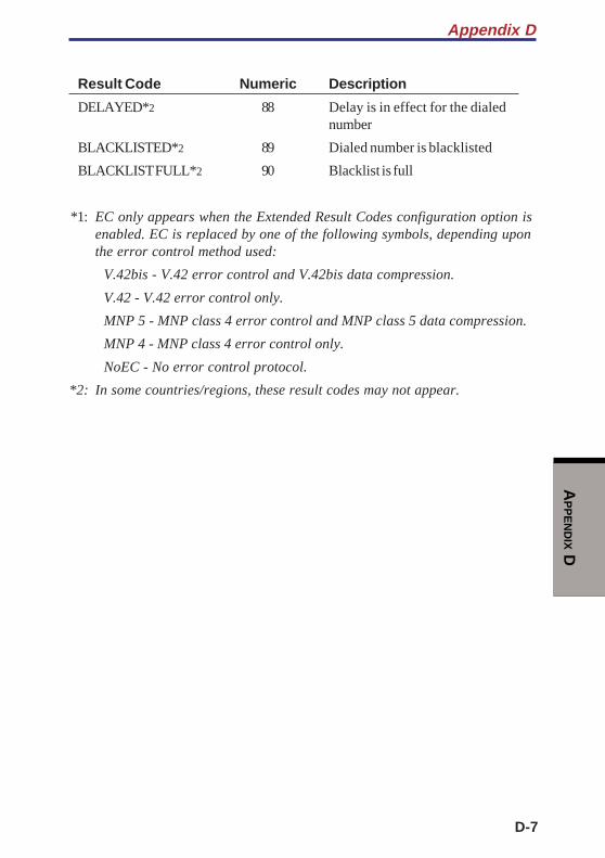
D-7
AP
PE
ND
IX D
Result Code Numeric Description
DELAYED*2 88 Delay is in effect for the dialednumber
BLACKLISTED*2 89 Dialed number is blacklisted
BLACKLIST FULL*2 90 Blacklist is full
*1: EC only appears when the Extended Result Codes configuration option isenabled. EC is replaced by one of the following symbols, depending uponthe error control method used:
V.42bis - V.42 error control and V.42bis data compression.
V.42 - V.42 error control only.
MNP 5 - MNP class 4 error control and MNP class 5 data compression.
MNP 4 - MNP class 4 error control only.
NoEC - No error control protocol.
*2: In some countries/regions, these result codes may not appear.
Appendix D

User's Manual
D-8
AP
PE
ND
IX D

E-1
AP
PE
ND
IX E
Appendix E
V.90The TOSHIBA internal modem uses V.90 technology. The modem is capable ofdownstream speeds of 56Kbps (kilobits per second) when connected to an Internetservice provider that supports V.90. As with any modem, the actual throughput(speed of data transfer) depends on analog telephone line conditions, which canvary considerably. Therefore, many users will experience throughput in the range of32-44Kbps under normal telephone line conditions. Upstream data flows at the V.34rate.
NOTE: V.90 rates can be achieved only when one V.90 capable modemis connected to another. The TOSHIBA Internal modem will selectautomatically V.34 if the remote modem lacks V.90 capability or if acombination of network and/or phone line conditions prevent V.90connection.
V.90 modeFunction Transmission speed
Data V.90 From 56K (maximum) to 28Kbps (minimum)
Reception only
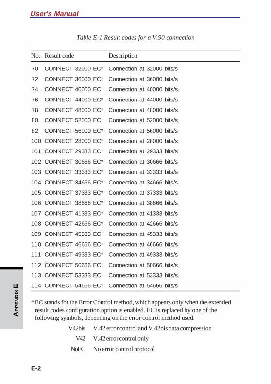
User's Manual
E-2
AP
PE
ND
IX E
Table E-1 Result codes for a V.90 connection
No. Result code Description
70 CONNECT 32000 EC* Connection at 32000 bits/s
72 CONNECT 36000 EC* Connection at 36000 bits/s
74 CONNECT 40000 EC* Connection at 40000 bits/s
76 CONNECT 44000 EC* Connection at 44000 bits/s
78 CONNECT 48000 EC* Connection at 48000 bits/s
80 CONNECT 52000 EC* Connection at 52000 bits/s
82 CONNECT 56000 EC* Connection at 56000 bits/s
100 CONNECT 28000 EC* Connection at 28000 bits/s
101 CONNECT 29333 EC* Connection at 29333 bits/s
102 CONNECT 30666 EC* Connection at 30666 bits/s
103 CONNECT 33333 EC* Connection at 33333 bits/s
104 CONNECT 34666 EC* Connection at 34666 bits/s
105 CONNECT 37333 EC* Connection at 37333 bits/s
106 CONNECT 38666 EC* Connection at 38666 bits/s
107 CONNECT 41333 EC* Connection at 41333 bits/s
108 CONNECT 42666 EC* Connection at 42666 bits/s
109 CONNECT 45333 EC* Connection at 45333 bits/s
110 CONNECT 46666 EC* Connection at 46666 bits/s
111 CONNECT 49333 EC* Connection at 49333 bits/s
112 CONNECT 50666 EC* Connection at 50666 bits/s
113 CONNECT 53333 EC* Connection at 53333 bits/s
114 CONNECT 54666 EC* Connection at 54666 bits/s
*EC stands for the Error Control method, which appears only when the extendedresult codes configuration option is enabled. EC is replaced by one of thefollowing symbols, depending on the error control method used.
V42bis V.42 error control and V.42bis data compression
V42 V.42 error control only
NoEC No error control protocol
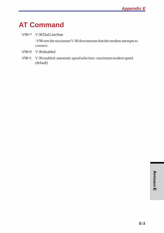
E-3
AP
PE
ND
IX E
AT Command-V90=* V.90 Dial Line Rate
-V90 sets the maximum V.90 downstream that the modem attempts toconnect.
-V90=0 V.90 disabled
-V90=1 V.90 enabled: automatic speed selection - maximum modem speed(default)
Appendix E

User's Manual
E-4
AP
PE
ND
IX E
F-1
AP
PE
ND
IX F
Appendix F
Wireless LANThis appendix is intended to help you get your Wireless LAN network up andrunning, with a minimum of parameters.
Card specificationsForm Factor Mini PCI TypeIII
Capability Wi-Fi (Wireless Fidelity) certified by the Wi-FiAlliance. The "Wi-Fi CERTIFIED" logo is acertification mark of the Wi-Fi Alliance.
Network Microsoft Windows® NetworkingOperatingSystem
Media Access CSMA/CA (Collision Avoidance) withProtocol Acknowledgment (ACK)Data Rate 54/48/36/24/18/12/ 9/6 Mb/s (Revision G)
11/5.5/2/1 Mb/s (Revision B)
Radio characteristicsRadio characteristics of Wireless LAN cards may vary according to:
Country/region where the product was purchased
Type of product
Wireless communication is often subject to local radio regulations. AlthoughWireless LAN wireless networking products have been designed for operation inthe license-free 2.4 GHz band, local radio regulations may impose a number oflimitations to the use of wireless communication equipment.
NOTE: Refer to the sheet Information to the User for regulatory informa-tion that may apply in your country/region.
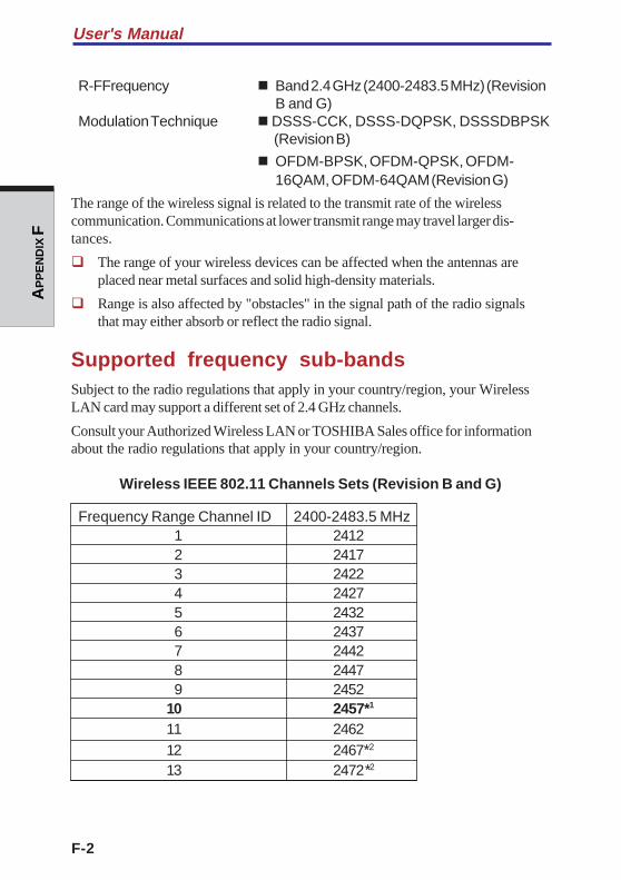
F-2
User's ManualA
PP
EN
DIX
F
R-FFrequency Band 2.4 GHz (2400-2483.5 MHz) (RevisionB and G)
Modulation Technique DSSS-CCK, DSSS-DQPSK, DSSSDBPSK (Revision B)
OFDM-BPSK, OFDM-QPSK, OFDM-16QAM, OFDM-64QAM (Revision G)
The range of the wireless signal is related to the transmit rate of the wirelesscommunication. Communications at lower transmit range may travel larger dis-tances.
The range of your wireless devices can be affected when the antennas areplaced near metal surfaces and solid high-density materials.
Range is also affected by "obstacles" in the signal path of the radio signalsthat may either absorb or reflect the radio signal.
Supported frequency sub-bandsSubject to the radio regulations that apply in your country/region, your WirelessLAN card may support a different set of 2.4 GHz channels.
Consult your Authorized Wireless LAN or TOSHIBA Sales office for informationabout the radio regulations that apply in your country/region.
Wireless IEEE 802.11 Channels Sets (Revision B and G)
Frequency Range Channel ID 2400-2483.5 MHz1 24122 24173 24224 24275 24326 24377 24428 24479 2452
10 2457*1
11 246212 2467*2
13 2472*2
F-3
AP
PE
ND
IX F
*1 Factory-set default channels
*2 Refer to the sheet Approved Countries/Regions for use for thecountries/regions that in which these channels can be used.
When installing Wireless LAN cards, the channel configuration is managed asfollows:
For wireless clients that operate in a Wireless LAN Infrastructure, the WirelessLAN card will automatically start operation at the channel identified by theWireless LAN Access Point. When roaming between different access pointsthe station can dynamically switch to another channel if required.
For Wireless LAN cards installed in wireless clients operating in a peer-to-peermode, the card will use the default channel 10.
In a Wireless LAN Access Point, the Wireless LAN card will use the factory-set default channel (printed in bold), unless the LAN Administrator selected adifferent channel when configuring the Wireless LAN Access Point device.
Appendix F

F-4
User's ManualA
PP
EN
DIX
F

G-1
AP
PE
ND
IX G
Appendix G
AC Power Cord andConnectorsThe power cord’s AC input plug must be compatible with the various internationalAC power outlets and the cord must meet the standards for the country/region inwhich it is used. All cords must meet the following specifications:
Length: Minimum 2 meters
Wire size: Minimum 0.75 mm2
Current rating: Minimum 2.5 amperes
Voltage rating: 125 or 250 VAC(depending on country/region’s power standards)
Certification agencies
U.S. and Canada: UL listed and CSA certified
No. 18 AWG, Type SVT or SPT-2 two conductor
Europe:
Austria: OVE Italy: IMQ
Belgium: CEBEC The Netherlands: KEMA
Denmark: DEMKO Norway: NEMKO
Finland: SETI Sweden: SEMKO
France: UTE Switzerland: SEV
Germany: VDE United Kingdom: BSI
Australia: AS
Japan: DENANHO
In Europe, power cords must be VDE type, H05VVH2-F and two conductor.
For the United States and Canada, plug configuration must be a 2-15P (250 V) or 1-15P (125 V) as designated in the U.S. National Electrical code handbook and theCanadian Electrical Code Part II.

G-2
User's ManualA
PP
EN
DIX
G
The following illustrations show the plug shapes for the U.S.A. and Canada, theUnited Kingdom, Australia and Europe.
USA and Canada United Kingdom
Australia Europe
UL approvedCSA approved BS approved
Approved by theappropriate agencyAS approved
H-1
AP
PE
ND
IX H
Appendix H
Internal Modem GuideThis appendix describes how to install and the remove the internal modem.
CAUTIONS: 1. Do not remove the base cover except to remove orinstall the internal modem or to check the PTT label.
2. Do not disassemble the computer beyond the stepsdescribed in this instruction or touch any componentsnot specifically described.
3. Always remove the Battery Pack and disconnect the ACAdaptor before removing the base cover.
4. Be careful not to drop any screws or other foreignmatter into the computer. Metal or other foreign mattercan damage the computer.
Installing the internal modem
NOTE: The internal modem is preinstalled. The following is for informa-tion only.
To install the modem board, follow the steps below.
1. Save your data, quit Windows and turn off the power.
2. Disconnect the AC Adaptor and any other peripheral devices.
3. Close the display panel and turn the computer over. Remove the Battery Pack.
4. Remove one screw under the Battery Pack slot.
5. Remove the memory slot cover and remove the fan cable.
6. Remove the cover of a hard disk drive slot.
7. Remove nine screws of the base cover of the computer, and remove the basecover.
8. Connect the modem cable to the modem board.
9. Secure the modem board with the two screws.
H-2
User’s ManualA
PP
EN
DIX
H
10. Seat the base cover and secure it with nine screws.
11. Seat the cover of a hard disk drive slot.
12. Connect the fan cable in a memory slot cover, and seat the memory slot cover.
13. Screw under the Battery Pack slot with the one screw.
14. Install the Battery Pack.
Removing the internal modemTo remove the internal modem.
1. Save your data, quit Windows and turn off the power.
2. Disconnect the AC Adaptor and any other peripheral devices.
3. Close the display panel and turn the computer over. Remove the Battery Pack.
4. Remove one screw under the Battery Pack slot.
5. Remove the memory slot cover and remove the fan cable.
6. Remove the cover of a hard disk drive slot.
7. Remove nine screws of the base cover of the computer, and remove the basecover.
NOTE: The standard (PTT) label can be checked.
8. Remove the two screws which are fixing the modem.
9. Disconnect the modem cable from the modem board.
10. Seat the base cover and secure it with nine screws.
11. Seat the cover of a hard disk drive slot.
12. Connect the fan cable in a memory slot cover, and seat the memory slot cover.
13. Screw under the Battery Pack slot with the one screw.
14. Install the Battery Pack.
The internal modem is approved by Japan Approvals Institute for Telecommuni-cations Equipment.
A02-0604JP
AP
PE
ND
IX I
I-1
Appendix I
Parts NumbersThe computer configuration and parts numbers, printed on a label on the bottom ofthe computer, indicate the CPU, LCD, memory, HDD and communication devices.

I-2
AP
PE
ND
IX I
ConfigurationsThe following table shows the computer configuration indicated on a label. Shaded areas indicate abbreviations used on the label.The explanations are to the left of the shading. Abbreviations are not limited to those in this chart. They may change withoutnotice.
* Figures indicate the CPU operating speed in megahertz. For example, PM1.7 means Mobile Intel® Pentium® -M processor1.7 GHz-M.
User's Manual

GL
OS
SA
RY
Glossary-1
GlossaryThe terms in this glossary cover the topics discussed in this manual. Alternatenaming is included for reference.
Abbreviations
AC: alternating current
ANSI: American National StandardsInstitute
APM: advanced power manager
ASCII: American Standard Code forInformation Interchange
BIOS: basic input output system
CMOS: complementary metal-oxidesemiconductor
CPU: central processing unit
CRT: cathode ray tube
DAA: Data Access Arrangement
DC: direct current
DDC: display data channel
DMA: direct memory access
DOS: disk operating system
DVI: Digital Visual Interface
ECP: extended capabilities port
EGA: enhanced graphics adaptor
FDD: floppy disk drive
FIR: fast infrared
HDD: hard disk drive
IDE: integrated drive electronics
I/O: input/output
IrDA: Infrared Data Association
IRQ: interrupt request
KB: kilobyte
LCD: liquid crystal display
LED: light emitting diode
LSI: large scale integration
MDA: monochrome display adaptor
MS-DOS: Microsoft Disk OperatingSystem
OCR: optical character recognition(reader)
PCB: printed circuit board
PCI: peripheral component intercon-nect
RAM: random access memory
RGB: red, green, and blue
ROM: read only memory
RTC: real time clock.
SCSI: small computer systeminterface
SIO: serial input/output
SVGA: super video graphics adaptor
TFT: thin-film transistor
UART: universal asynchronousreceiver/transmitter
USB: Universal Serial Bus

GL
OS
SA
RY
Glossary-2
ANSI: American National StandardsInstitute. An organization establishedto adopt and define standards for avariety of technical disciplines. Forexample, ANSI defined the ASCIIstandard and other informationprocessing requirements.
antistatic: A material used to preventthe buildup of static electricity.
application: A group of programsthat together are used for a specifictask such as accounting, financialplanning, spreadsheets, word process-ing, and games, etc.
ASCII: American Standard Code forInformation Interchange. ASCII codeis a set of 256 binary codes thatrepresent the most commonly usedletters, numbers, and symbols.
async: Short for asynchronous.
asynchronous: Lacking regular timerelationship. As applied to computercommunications, asynchronous refersto the method of transmitting data thatdoes not require a steady stream of bitsto be transmitted at regular timeintervals.
AUTOEXEC.BAT: A batch file thatexecutes a series of MS-DOS com-mands and programs each time youstart the computer.
(Abbreviations continued)
VESA: Video Electronic StandardsAssociation
VGA: video graphics array
VRT: voltage reduction technology
A
adaptor: A device that provides aninterface between two dissimilarelectronic devices. For example, theAC adaptor modifies the power from awall outlet for use by the computer.This term also refers to the add-incircuit cards that control externaldevices, such as video monitors andmagnetic tape devices.
allocate: To assign a space orfunction for a specific task.
alphanumeric: Keyboard charactersincluding letters, numbers and othersymbols, such as punctuation marks ormathematical symbols.
alternating current (AC): Electriccurrent that reverses its direction offlow at regular intervals.
analog signal: A signal whosecharacteristics such as amplitude andfrequency vary in proportion to (arean analog of) the value to be transmit-ted. Voice communications are analogsignals.
adaptor

GL
OS
SA
RY
Glossary-3
B
backup: A duplicate copy of files keptas a spare in case the original isdestroyed.
batch file: A file that can be executedfrom the system prompt containing asequence of operating system com-mands or executable files. See alsoAUTOEXEC.BAT.
binary: The base two number systemcomposed of zeros and ones (off oron), used by most digital computers.The right most digit of a binarynumber has a value of 1, the next avalue of 2, then 4, 8, 16, and so on.For example, the binary number 101has a value of 5. See also ASCII.
BIOS: Basic Input Output System.The firmware that controls data flowwithin the computer. See also firm-ware.
bit: Derived from “binary digit,” thebasic unit of information used by thecomputer. It is either zero or one.Eight bits is one byte. See also byte.
Bluetooth: A short-range radiotechnology designed to simplifywireless communication amongcomputers, communication devicesand the Internet.
board: A circuit board. An internalcard containing electronic components,called chips, which perform a specificfunction or increase the capabilities ofthe system.
boot: Short for bootstrap. A programthat starts or restarts the computer.The program reads instructions from astorage device into the computer’smemory.
bps: Bits per second. Typically usedto describe the data transmissionspeed of a modem.
buffer: The portion of the computer’smemory where data is temporarilystored. Buffers often compensate fordifferences in the rate of flow fromone device to another.
bus: An interface for transmission ofsignals, data or electric power.
byte: The representation of a singlecharacter. A sequence of eight bitstreated as a single unit; also thesmallest addressable unit within thesystem.
C
cache memory: High speed memorywhich stores data that increasesprocessor speed and data transfer rate.When the CPU reads data from mainmemory, it stores a copy of this data incache memory. The next time the CPUneeds that same data, it looks for it inthe cache memory rather than the mainmemory, which saves time. Thecomputer has two cache levels. Levelone is incorporated into the processorand level two resides in externalmemory.
cache memory

GL
OS
SA
RY
Glossary-4
capacity: The amount of data that canbe stored on a magnetic storagedevice such as a diskette (floppydisk) or hard disk. It is usuallydescribed in terms of kilobytes (KB),where one KB = 1024 bytes andmegabytes (MB), where one MB =1024 KB.
card: Synonym for board. See board.
CardBus: An industry standard busfor 32-bit PC Cards.
CD-ROM: A Compact Disk-ReadOnly Memory is a high capacity diskthat can be read from but not writtento. The CD-ROM drive uses a laser,rather than magnetic heads, to readdata from the disk.
character: Any letter, number,punctuation mark, or symbol used bythe computer. Also synonymous withbyte.
chassis: The frame containing thecomputer.
chip: A small semiconductor contain-ing computer logic and circuitry forprocessing, memory, input/outputfunctions and controlling other chips.
CMOS: Complementary Metal-OxideSemiconductor. An electronic circuitfabricated on a silicon wafer thatrequires very little power. Integratedcircuits implemented in CMOStechnology can be tightly packagedand are highly reliable.
cold start: Starting a computer that iscurrently off (turning on the power).
commands: Instructions you enter atthe terminal keyboard that direct theactions of the computer or its periph-eral devices.
communications: The means bywhich a computer transmits andreceives data to and from anothercomputer or device.
Compact Flash: A small removablemass storage device, designed withflash technology, a non-volatilestorage solution that does not requirea battery to retain data indefinitely.
compatibility: 1) The ability of onecomputer to accept and process data inthe same manner as another computerwithout modifying the data or themedia upon which it is being trans-ferred. 2) the ability of one device toconnect to or communicate withanother system or component.
components: Elements or parts (of asystem) which make up the whole(system).
computer program: A set of instruc-tions written for a computer thatenable it to achieve a desired result.
computer system: A combination ofhardware, software, firmware, andperipheral components assembled toprocess data into useful information.
configuration: The specific compo-nents in your system (such as theterminal, printer, and disk drives) andthe settings that define how your
capacity

GL
OS
SA
RY
Glossary-5
system works. You use the HW Setupprogram to control your systemconfiguration.
control keys: A key or sequence ofkeys you enter from the keyboard toinitiate a particular function within aprogram.
controller: Built-in hardware andsoftware that controls the functions ofa specific internal or peripheral device(e.g. keyboard controller).
co-processor: A circuit built into theprocessor that is dedicated to intensivemath calculations.
CPS: Characters per second. Typi-cally used to indicate the transmissionspeed of a printer.
CPU: Central processing unit. Theportion of the computer that interpretsand executes instructions.
CRT: Cathode Ray Tube. A vacuumtube in which beams projected on afluorescent screen-producing luminousspots. An example is the televisionset.
cursor: A small, blinking rectangle orline that indicates the current positionon the display screen.
D
data: Information that is factual,measurable or statistical that acomputer can process, store, orretrieve.
data access arrangement: Circuitrythat isolates a modem or other devicefrom telephone lines.
data bits: A data communicationsparameter controlling the number ofbits (binary digits) used to make up abyte. If data bits = 7 the computer cangenerate 128 unique characters. Ifdata bits = 8 the computer cangenerate 256 unique characters.
DC: Direct Current. Electric currentthat flows in one direction. This typeof power is usually supplied bybatteries.
default: The parameter valueautomatically selected by the systemwhen you or the program do notprovide instructions. Also called apreset value.
delete: To remove data from a diskor other data storage device. Synony-mous with erase.
device driver: A program thatcontrols communication between aspecific peripheral device and thecomputer. The CONFIG.SYS filecontains device drivers that MS-DOSloads when you turn the computer on.
dialog box: A window that acceptsuser input to make system settings orrecord other information.
disk drive: The device that randomlyaccesses information on a disk andcopies it to the computer’s memory. Italso writes data from memory to thedisk. To accomplish these tasks, the
disk drive
GL
OS
SA
RY
Glossary-6
unit physically rotates the disk at highspeed past a read-write head.
disk storage: Storing data on magneticdisk. Data is arranged on concentrictracks much like a phonograph record.
diskette: A removable disk that storesmagnetically encoded data used on amicrocomputer. Also called floppydisk.
display: A CRT, plasma screen, LCD,or other image producing device usedto view computer output.
documentation: The set of manualand/or other instructions written for theusers of a computer system or applica-tion. Computer system documentationtypically includes procedural andtutorial information as well as systemfunctions.
DOS: Disk operating system. Seeoperating system.
driver: A software program, generallypart of the operating system, thatcontrols a specific piece of hardware(frequently a peripheral device such asa printer or mouse).
E
echo: To send back a reflection of thetransmitted data to the sending device.You can display the information on thescreen, or output it to the printer, orboth. When a computer receives backdata it transmitted to a CRT (or other
peripheral device) and then retrans-mits the data to printer, the printer issaid to echo the CRT.
erase: See delete.
escape: 1) A code ( ASCII code 27),signaling the computer that whatfollows are commands; used withperipheral devices such as printers andmodems. 2) A means of aborting thetask currently in progress.
escape guard time: A time before andafter an escape code is sent to themodem which distinguishes betweenescapes that are part of the transmit-ted data, and escapes that are in-tended as a command to the modem.
execute: To interpret and execute aninstruction.
Extended Capability Port: An industrystandard that provides a data buffer,switchable forward and reverse datatransmission, and run length encoding(RLE) support.
F
fast infrared: An industry standardthat enables cableless infrared serialdata transfer at speeds of up to 4Mbps.
file: A collection of related informa-tion; a file can contain data, programs,or both.
firmware: A set of instructions builtinto the hardware which controls and
disk storage
GL
OS
SA
RY
Glossary-7
directs a microprocessor’s activities.
fixed disk: See hard disk.
floppy disk: See diskette.
floppy disk drive (FDD): An electrome-chanical device that reads and writes tofloppy disks. See also diskette.
Fn-esse: A TOSHIBA utility that letsyou assign functions to hotkeys.
folder: An icon in Windows used tostore documents or other folders.
format: The process of readying ablank disk for its first use. Formattingestablishes the structure of the diskthat the operating system expectsbefore it writes files or programs ontothe disk.
function keys: The keys labeled F1through F12 that tell the computer toperform certain functions.
G
gigabyte (GB): A unit of datastorage equal to 1024 megabytes.See also megabyte.
GND: Ground. An RS-232C signalused in the exchange of data between acomputer and serial device.
graphics: The use of drawings,pictures, or other images, such ascharts or graphs, to present informa-tion.
H
hard disk: A non-removable diskusually referred to as drive C. Thefactory installs this disk and only atrained engineer can remove it forservicing. Also called fixed disk.
hard disk drive (HDD): An electro-mechanical device that reads andwrites a hard disk. See also hard disk.
hardware: The physical electronicand mechanical components of acomputer system: typically, thecomputer itself, external disk drives,etc. See also software and firmware.
hertz: A unit of wave frequency thatequals one cycle per second.
hexadecimal: The base 16 numberingsystem composed of the digits 0through 9 and the letters A, B, C, D, E,and F.
host computer: The computer thatcontrols, regulates, and transmitsinformation to a device or anothercomputer.
hot dock/undock: Connecting ordisconnecting a device to or from thecomputer while the computer’s poweris turned on.
hotkey: The computer’s feature inwhich certain keys in combinationwith the extended function key, Fn,can be used to set system parameters,such as speaker volume.
hotkey
GL
OS
SA
RY
Glossary-8
HW Setup: A TOSHIBA utility thatlets you set the parameters for varioushardware components.
I
icon: A small graphic image displayedon the screen or in the indicator panel.In Windows, an icon represents anobject that the user can manipulate.
infrared port: A cableless communi-cations capable of using infraredsignals to send serial data.
input: The data or instructions youprovide to a computer, communicationdevice or other peripheral device fromthe keyboard or external or internalstorage devices. The data sent (oroutput) by the sending computer isinput for the receiving computer.
instruction: Statements or commandsthat specify how to perform a particu-lar task.
interface: 1) Hardware and/orsoftware components of a systemused specifically to connect onesystem or device to another. 2) Tophysically connect one system ordevice to another to exchangeinformation. 3) The point of contactbetween user, the computer, and theprogram, for example, the keyboard ora menu.
interrupt request: A signal that givesa component access to the processor.
I/O: Input/output. Refers to accep-tance and transfer of data to and froma computer.
I/O devices: Equipment used tocommunicate with the computer andtransfer data to and from it.
J
jumper: A small clip or wire thatallows you to change the hardwarecharacteristics by electrically connect-ing two points of a circuit.
K
K: Taken from the Greek word kilo,meaning 1000; often used as equiva-lent to 1024, or 2 raised to the 10thpower. See also byte and kilobyte.
KB: See kilobyte.
keyboard: An input device containingswitches that are activated by manu-ally pressing marked keys. Eachkeystroke activates a switch thattransmits a specific code to thecomputer. For each key, the transmit-ted code is, in turn, representative ofthe (ASCII) character marked on thekey.
kilobyte (KB): A unit of data storageequal to 1024 bytes. See also byte andmegabyte.
HW Setup
GL
OS
SA
RY
Glossary-9
.
menu: A software interface thatdisplays a list of options on thescreen. Also called a screen.
microprocessor: A hardware compo-nent contained in a single integratedcircuit that carries out instructions.Also called the central processing unit(CPU), one of the main parts of thecomputer.
mode: A method of operation, forexample, the boot mode or the resumemode.
modem: Derived from modulator/demodulator, a device that converts(modulates) digital data for transmis-sion over telephone lines and thenconverts modulated data (demodu-lates) to digital format where received.
monitor: A device that uses rows andcolumns of pixels to display alphanu-meric characters or graphic images.See CRT.
motherboard: A name sometimesused to refer to the main printed circuitboard in processing equipment. Itusually contains integrated circuitsthat perform the processor’s basicfunctions and provides connectors foradding other boards that performspecial functions. Sometimes called amain board.
motherboard
L
level 2 cache: See cache.
Light Emitting Diode (LED): Asemiconductor device that emits lightwhen a current is applied.
Liquid Crystal Display (LCD): Liquidcrystal sealed between two sheets ofglass coated with transparent con-ducting material. The viewing-sidecoating is etched into characterforming segments with leads thatextend to the edge of the glass.Applying a voltage between the glasssheets darkens the liquid crystal toprovide contrast to lighted portions ofthe display.
LSI: Large Scale Integration. 1) Atechnology that allows the inclusion ofup to 100,000 simple logic gates on asingle chip. 2) An integrated circuitthat uses the large scale integration.
M
main board: See motherboard.
megabyte (MB): A unit of datastorage equal to 1024 kilobytes. Seealso kilobyte.
megahertz: A unit of wave frequencythat equals 1 million cycles persecond. See also hertz.
GL
OS
SA
RY
Glossary-10
N
non-system disk: A formatted diskette(floppy disk) you can use to storeprograms and data but you cannot useto start the computer. See system disk.
nonvolatile memory: Memory, usuallyread-only (ROM), that is capable ofpermanently storing information.Turning the computer’s power offdoes not alter data stored in nonvola-tile memory.
numeric keypad overlay: A featurethat allows you to use certain keys onthe keyboard to perform numericentry, or to control cursor and pagemovement.
O
OCR: Optical Character Recognition(reader). A technique or device thatuses laser or visible light to identifycharacters and input them into astorage device.
OCR wand: A device that reads, usingan optical device, hand written ormachine printed symbols into acomputer. See also OCR.
online state: A functional state of aperipheral device when it is ready toreceive or transmit data.
operating system: A group ofprograms that controls the basicoperation of a computer. Operating
system functions include interpretingprograms, creating data files, andcontrolling the transmission andreceipt (input/output) of data to andfrom memory and peripheral devices.
output: The results of a computeroperation. Output commonly indicatesdata 1) printed on paper, 2) displayedat a terminal, 3) sent through the serialport of internal modem, or 4) stored onsome magnetic media.
P
parity: 1) The symmetrical relationshipbetween two parameter values(integers) both of which are either onor off; odd or even; 0 or 1. 2) In serialcommunications, an error detection bitthat is added to a group of data bitsmaking the sum of the bits even orodd. Parity can be set to none, odd, oreven.
password: A unique string of charac-ters used to identify a specific user.The computer provides various levelsof password protection such as user,supervisor and eject.
pel: The smallest area of the displaythat can be addressed by software.Equal in size to a pixel or group ofpixels. See pixel.
peripheral component interconnect:An industry standard 32-bit bus.
non-system disk
GL
OS
SA
RY
Glossary-11
peripheral device: An I/O device thatis external to the central processor and/or main memory such as a printer or amouse.
pixel: A picture element. The smallestdot that can be made on a display orprinter. Also called a pel.
plug and play: A capability withWindows that enables the system toautomatically recognize connections ofexternal devices and make the neces-sary configurations in the computer.
port: The electrical connectionthrough which the computer sends andreceives data to and from devices orother computers.
printed circuit board (PCB): Ahardware component of a processor towhich integrated circuits and othercomponents are attached. The boarditself is typically flat and rectangular,and constructed of fiberglass, to formthe attachment surface.
program: A set of instructions acomputer can execute that enables it toachieve a desired result. See alsoapplication.
prompt: A message the computerprovides indicating it is ready for orrequires information or an action fromyou.
R
Radio frequency interference (RFI)shield: A metal shield enclosing theprinted circuit boards of the printer orcomputer to prevent radio and TVinterference. All computer equipmentgenerates radio frequency signals.The FCC regulates the amount ofsignals a computing device can allowpast its shielding. A Class A device issufficient for office use. Class Bprovides a more stringent classifica-tion for home equipment use.TOSHIBA portable computers complywith Class B computing deviceregulations.
Random Access Memory (RAM):High speed memory within thecomputer circuitry that can be read orwritten to.
restart: Resetting a computer withoutturning it off (also called ‘warm boot’or ‘soft reset’). To restart the com-puter, press Ctrl + Alt + Del while thecomputer is on. See also boot.
RGB: Red, green, and blue. A devicethat uses three input signals, eachactivating an electron gun for aprimary additive color (red, green, andblue) or port for using such a device.See also CRT.
RJ11: A modular telephone jack.
RJ11

GL
OS
SA
RY
Glossary-12
subpixel: Three elements, one red,one green and blue (RGB), that makeup a pixel on the color LCD. Thecomputer sets subpixels indepen-dently, each may emit a differentdegree of brightness. See also pixel.
synchronous: Having a constant timeinterval between successive bits,characters or events.
system disk: A disk that has beenformatted with an operating system.For MS-DOS the operating system iscontained in two hidden files and theCOMMAND.COM file. You can boota computer using a system disk. Alsocalled an operating system disk.
T
Tablet PC: A fully functional com-puter that runs Microsoft WindowsXP Tablet PC Edition. With a TabletPC, you can write directly on thescreen by using a tablet pen and usethe pen to perform mouse functions.
terminal: A typewriter-like keyboardand CRT display screen connected tothe computer for data input/output.
TFT: A color LCD technology thatapplies individual transistors to eachpixel enabling fine display control andexcellent screen legibility.
TOSHIBA Power Saver: A TOSHIBAutility that lets you set the parametersfor various power-saving functions.
ROM
ROM: Read Only Memory: Anonvolatile memory chip manufac-tured to contain information thatcontrols the computer’s basic opera-tion. You cannot access or changeinformation stored in ROM.
S
SCSI: Small Computer SystemInterface is an industry standardinterface for connection of a variety ofperipheral devices.
SD card: SD (Secure Digital) card wasdeveloped as a non-volatile memorycard with a postage stamp size(24X32X2.1 mm). SD card is featuringthe function of copyright protection.
SIO: Serial Input/Output. Theelectronic methodology used in serialdata transmission.
soft key: Key combinations thatemulate keys on the IBM keyboard,change some configuration options,stop program execution, and accessthe numeric keypad overlay.
software: The set of programs,procedures and related documentationassociated with a computer system.Specifically refers to computer programsthat direct and control the computersystem’s activities. See also hardware.
stop bit: One or more bits of a bytethat follow the transmitted character orgroup codes in asynchronous serialcommunications.
GL
OS
SA
RY
Glossary-13
TOSHIBA tablet pen: An input devicefor Tablet PC. User can write thecharacter on a display screen with adigitizing function or tap to select theitem appearing on the screen using thetablet pen.
Touch pad: A pointing device inte-grated into the TOSHIBA computerpalm rest.
TTL: Transistor-transistor logic. Alogic circuit design that uses switchingtransistors for gates and storage.
U
Universal Serial Bus: This serialinterface lets you communicate withseveral devices connected in a chain toa single port on the computer.
V
VGA: Video graphics array is anindustry standard video adaptor thatlets you run any popular software.
volatile memory: Random accessmemory (RAM) that stores informationas long as the computer is connectedto a power source.
write protection
W
Warm dock/undock: Connecting ordisconnecting a device to or from thecomputer while the computer issuspended.
warm start: Restarting or resetting acomputer without turning it off.
window: A portion of the screen thatcan display its own application ordocument. Often used to mean aMicrosoft Windows window.
Wireless LAN: A short-range radiotechnology designed to simplifywireless communication with otherLAN systems based on DirectSequence Spread Spectrum radiotechnology that complies with theIEEE 802.11 Standard (Revision B).
write protection: A method forprotecting a diskette (floppy disk)from accidental erasure.

GL
OS
SA
RY
Glossary-14
Index-1
INDEX
Index
AAC adaptor 1-4, 2-12
DC IN 15V port 2-4connecting 3-6universal 1-12, 8-10
ASCII characters 5-9Auto power on, See Power
BBattery, See also Battery Pack
charging 6-9extending life 6-12indicator 2-9, 6-3lock 2-6, 6-14monitoring capacity 6-10real time clock 1-4, 6-5safety precautions 6-6save mode 1-7types 6-4
Battery Charger 1-12, 8-11Battery Pack 1-4, 1-11, 6-5
location 2-5replacing 6-13
Bluetooth 1-6, 4-17Boot priority 7-3
CCache memory
Level 2 cache 1-3Charger, See Battery ChargerCleaning the computer 4-27Cooling, See Heat dispersal
DDC IN 15V indicator 2-10, 6-3Disk indicator 2-9Diskette care 4-15Display 1-3, 2-7, See also Video
modes and Monitor externalautomatic power off 1-7controller 1-3, Appendix Bdriver 1-9hinge 2-7opening 3-8selection, See Hot keys
Documentation list 1-2
EEnvironment, See Work spaceEquipment checklist 1-1Equipment setup
general conditions 3-2placement 3-3
Ergonomicslighting 3-4seating and posture 3-3work habits 3-4
Expansion memory, See Memoryexpansion
FFn + Ctrl (enhanced keyboard simula-
tion) 5-3Fn + Enter 5-3Fn + Esc (sound mute) 5-4Fn-esse 1-9Fn + F1 (instant security) 5-4Fn + F2 (power save mode) 5-4
Index-2
User's ManualINDEX
Fn + F3 (standby) 5-4Fn + F4 (hibernation) 5-5Fn + F5 (display selection) 5-5Fn + F6 (display brightness) 5-5Fn + F7 (display brightness) 5-5Fn + F8 (wireless setting) 5-6Fn + F9 (touch pad) 5-6Fn + F10 (arrow mode) 5-3, 5-8Fn + F11 (numeric mode) 5-3, 5-8Fn + F12 (ScrLock) 5-3Fn Sticky key 5-7Function Keys 5-2
HHard disk drive 1-3
automatic power off 1-7problems 9-9
Heat dispersal 1-8Hibernation 1-8, 5-5Hotkeys 1-7, 5-4
display brightness 5-5display selection 5-5hibernation 5-5instant security 5-4power save mode 5-4standby 5-4sticky key utility 5-7
HW Setup 1-9accessing 7-1Boot Priority 7-3CPU 7-2Device Config 7-2Display 7-2General 7-1Keyboard 7-5LAN 7-6USB 7-5window 7-1
IIndicators 2-9, 6-3
Infrared port, See also Portsproblems 9-10
Instant security, See Hot keysInterfaces, See Ports
KKeyboard 1-4, 5-1
emulating enhanced keyboard 5-2F1 . . . F12 function keys 5-2problems 9-8Typewriter keys 5-1
Keypad overlay 1-7, 5-7arrow mode 5-8numeric mode 5-8temporarily changing modes 5-9temporarily using normal keyboard
(overlay on) 5-8temporarily using overlay (overlay
off) 5-9turning on 5-7Windows special keys 5-7
LLAN, See also Wireless LAN 1-6
active indicator 2-5cable types 4-19connecting 4-19disconnecting 4-20jack location 2-4problems 9-19using 4-19
Laptop mode 3-5LCD, See Display, Video modes and
Monitor externalLevel 2 cache, See Cache memoryLock, security, See Security lock
MMemory 1-3
expansion 1-11, 8-6installing 8-7
Index-3
INDEX
removing 8-9slots 1-3
Microphone, See sound system,microphone
Microprocessor, See ProcessorModem 1-5, 4-24
connecting 4-26disconnecting 4-27jack location 2-4problems 9-17properties menu 4-25region selection 4-25
Monitor external 8-12, See alsoVideo modes and Ports
problems 9-14Moving the computer 4-28
NNumeric keypad, See Keypad overlay
OOperating system, See WindowsOverlay, See Keypad overlay
PPanel power on/off, See PowerPassword
power on 1-7starting the computer with 6-18supervisor 1-9, 6-17user 6-16
PC card 1-5inserting 8-2location of slots 2-2problems 9-13removing 8-4
PortsDC IN 15V 2-4external monitor 1-5, 2-4headphone, See Sound systeminfrared 1-4, 2-1
LAN 2-5microphone, See Sound systemmodem 2-5USB 1-5, 2-4
Powerauto power on 1-8button location 2-7indicator 2-9, 6-4panel power on/off 1-8restarting 3-15turning off 3-10turning on 3-9system auto off 1-7
Power cord 1-4, 2-11, Appendix GProblems
AC power 9-5analyzing symptoms 9-2battery 9-6Bluetooth 9-20diskette drive 9-9hard disk drive 9-8hardware and system checklist 9-3infrared port 9-10keyboard 9-8LAN 9-19LCD panel 9-8memory expansion 9-16modem 9-17monitor, external 9-14password 9-7PC card 9-13pointing device 9-10power 9-4preliminary checklist 9-1SD card 9-14self test 9-4sound system 9-15support from TOSHIBA 9-21system start-up 9-3TOSHIBA Tablet PC Pen 9-10Touch Pad 9-11USB 9-15
Index
Index-4
User's ManualIN
DE
X
USB mouse 9-12Wireless LAN 9-19
Processor 1-3
R
Real time clock battery, See BatteryRecovery CD-ROM 3-15Reserve pen 1-4, 1-12, 4-2
S
Screen, See Displayorientation 4-10
ScrLock (Fn + F12), See Soft keysSD card 1-5
indicator 2-2inserting 8-4location of slot 2-1problems 9-14removing 8-4
Security lock 1-12attaching 8-13location 2-3
Self Test, See ProblemsSensor switch 2-8Soft keys 5-2
cursor control mode 5-3Enter 5-3numeric mode 5-8right Ctrl key 5-3ScrLock 5-3
Sound system 1-5drivers 1-10headphone 1-5, 2-1microphone 1-5, 2-1problems 9-15speaker 2-8
Standby 1-8System auto off 1-7
T
Tablet mode 3-5
Tablet Multi Dock 8-11Tablet PC 3-5Tablet PC Pen 1-1, 1-4, 1-12, 4-2TOSHIBA Console 1-2TOSHIBA Power Saver 1-2 Touch Pad 1-4, 2-7
control buttons 2-7, 4-1problems 9-11using 4-1
Troubleshooting, See Problems
U
Utilitieslist 1-9
USB 1-5location 2-4problems 9-15
USB FDD Kit 1-11, 8-11connecting 4-14disconnecting 4-15problems 9-9using 4-13
V
Video modes, Appendix BVideo RAM 1-3
W
Wireless communicationindicator 2-9, 4-18switch 2-3, 4-18
Wireless LAN 1-6, 4-16problems 9-19using 4-16
Work space 3-3