TorqueMaster Replacement Spring - Wayne Dalton · TorqueMaster™ Replacement Spring Components for...
12
283753 TorqueMaster ™ Replacement Spring Installation Instructions NOTE: Use these installation instructions in conjunction with the TorqueMaster ™ Repair / Replacement Spring Program literature. ©Copyright 2016 Wayne Dalton, a division of Overhead Door Corporation REV2 05/03/2016
Transcript of TorqueMaster Replacement Spring - Wayne Dalton · TorqueMaster™ Replacement Spring Components for...

283753
TorqueMaster™ Replacement Spring
Installation InstructionsNOTE: Use these installation instructions in conjunction with the TorqueMaster™ Repair / Replacement Spring Program literature.
©Copyright 2016 Wayne Dalton, a division of Overhead Door Corporation REV2 05/03/2016

Description
Ite
m n
o.
Lh spring assembly
Qu
antit
y
A1 1
A4 1
1A3
Description
Item
no.
Qu
antit
y
A1 1
A4 1
A2 1
1
Rh spring assembly
Counter gear
Rh counter cover assembly
TorqueMaster™ Replacement Spring Components forLeft Hand and Right Hand Assemblies
A5 1
A2
Oil lubricantOil lubricant
Counter gear 1
A3
2
TABLE OF CONTENTS
• Replacement Spring Components Page 2
• Single Spring TorqueMaster™ Removal Page 3
• Double Spring TorqueMaster™ Remova Page 5
• Single Spring TorqueMaster™ Reinstallation Page 7
• Double Spring TorqueMaster™ Reinstallation Page 10
Lh counter cover assembly
Lh winding shaft

Removal Instructions forTorqueMaster™ Single Spring System
A TorqueMaster™ Single spring system can be identified by the end brackets. The right hand end bracket will have a drive gear, counter gear, counter assembly, and a winding bolt head. The left hand end bracket will have no gears, counter assembly, or winding bolt head. The hole for the winding bolt head will be plugged.
Step 1 Check for spring tension by pulling the counterbalance cable on the right hand cable drum away from the header (Fig. 2-1). If there is no spring tension the cable will be loose. In addition, the torque tube should be free to rotate in either direction. If there is no spring ten-sion, loosen the lock nut 1/4 turn (Fig. 2-2) and proceed to Step 3. If the counterbalance cable is still taut and the torque tube is difficult to rotate, that is an indication that spring tension still exists. Place a mark on the drive gear tooth and an adjacent mark on the right hand end bracket (Fig. 2-2). Loosen the lock nut 1/4 turn using a 7/16” wrench.
IMPORTANT! RIGHT AND LEFT HAND IS ALWAYS DETERMINED FROM INSIDE THE BUILDING LOOKING OUT.
Step 2 Using an electric drill (High torque / gear reduced to 1300 rpm pre-ferred) with a 7/16” hex head driver, unwind the right hand winding bolt head counterclockwise (Fig. 2-3) and count the number of turns the mark on the drive gear passes the adjacent mark on the end bracket. Referencing the chart below, by door height, stop unwinding the spring once the counted turns have reached the listed number of turns. 6’-0” Door Height = 14 turns 6’-3” Door Height = 14 1/2 turns 6’-6” Door Height = 15 turns 6’-9” Door Height = 15 1/2 turns 7’-0” Door Height = 16 turns 7’-3” Door Height = 16 1/2 turns 7’-6” Door Height = 17 turns 7’-9” Door Height = 17 1/2 turns 8’-0” Door Height = 18 turns
DO NOT USE IMPACT GUN TO UNWIND SPRINGS.
IMPORTANT! DO NOT REFERENCE THE COUNTER ASSEMBLY WHEN COUNTING THE NUMBER OF TURNS BEING UNWOUND ON THE RIGHT HAND SPRING, BUT FOLLOW THE INSTRUCTIONS ABOVE.
Step 3 Using a flat head screwdriver, pry the counter gear and counter as-sembly from the right hand end bracket (Fig. 2-4). Discard the counter gear and counter assembly.
Fig. 2-1
Fig. 2-2
Fig. 2-3
3

Step 4
Remove the upper 5/16” x 1-5/8” lag screw from the right hand end bracket (Fig. 2-5). Attach locking pliers to the upper portion of the end bracket and hold the housing steady while removing the lower 5/16” x 1-5/8” lag screw and #10 x 1/2” phillips head screw from the end bracket (Fig. 2-6).
Step 5
Holding the right hand end bracket steady with locking pliers, carefully pry the end bracket and drive gear off the winding shaft using a flat head screwdriver (Fig. 2-7).
THE WINDING SHAFT MAY ROTATE WHEN REMOVING THE END BRACKET AND DRIVE GEAR.
Step 6 Repeat Step 4 for the left hand side. Holding the left hand end bracket steady with locking pliers, carefully pry the end bracket off the wind-ing shaft using a flat head screwdriver (Fig. 2-7).
Step 7 Lift the right hand side of the torque tube and slide the cable drum off. Realign the groove in the winding shaft with the radial notch in the flagangle and drape the counterbalance cable with drum over the flagangle. Lift the left hand side of the torque tube and slide the cable drum and winding shaft off (Fig. 2-8). Drape the counterbalance cable with drum over the flagangle. Bend the center bracket tab over to allow lifting the torque tube up. Lay the tube on the floor and remove the right hand spring from the torque tube.
NOTE: The cable drums and right hand spring may be difficult to remove. If so, lightly tap the cable drum and cam tube with a hammer to aid removal.
4
Fig. 2-5
Fig. 2-4
Fig. 2-6
Fig. 2-7
Fig. 2-8

Removal Instructions forTorqueMaster™ Double Spring System
A TorqueMaster™ Double spring system can be identified by the end brackets. The left and right hand end brackets will have a drive gear, counter gear, counter assembly, and winding bolt heads.
Step 1
Place a mark on the drive gear tooth and an adjacent mark on the right hand end bracket (Fig. 3-1). Loosen the lock nut 1/4 turn using a 7/16” wrench.
IMPORTANT! RIGHT AND LEFT HAND IS ALWAYS DETERMINED FROM INSIDE THE BUILDING LOOKING OUT.
Step 2
Using an electric drill (High torque / gear reduced to 1300 rpm pre-ferred) with a 7/16” hex head driver, unwind the right hand winding bolt head counterclockwise (Fig. 3-2) and count the number of turns the mark on the drive gear passes the adjacent mark on the end bracket. Referencing the chart below, by door height, stop unwinding the spring once the counted turns have reached the listed number of turns.
6’-0” Door Height = 14 turns 6’-3” Door Height = 14 1/2 turns 6’-6” Door Height = 15 turns 6’-9” Door Height = 15 1/2 turns 7’-0” Door Height = 16 turns 7’-3” Door Height = 16 1/2 turns 7’-6” Door Height = 17 turns 7’-9” Door Height = 17 1/2 turns 8’-0” Door Height = 18 turns
DO NOT USE IMPACT GUN TO UNWIND SPRINGS.
IMPORTANT! DO NOT REFERENCE THE COUNTER ASSEMBLY WHEN COUNTING THE NUMBER OF TURNS BEING UNWOUND ON THE SPRING, BUT FOLLOW THE INSTRUCTIONS ABOVE.
Step 3
Verify that spring tension has been released by pulling the counterbal-ance cable on the right hand cable drum away from the header (Fig. 3-3). If spring tension has been released, the cable will be loose. In addition, the torque tube should be free to rotate in either direction. If the counterbalance cable is still taut and the torque tube is difficult to rotate, that is an indication that spring tension still exists on the left hand spring. Repeat Steps 1 and 2 for releasing spring tension on the left hand side.
Fig. 3-1
Fig. 3-2
Fig. 3-3
5
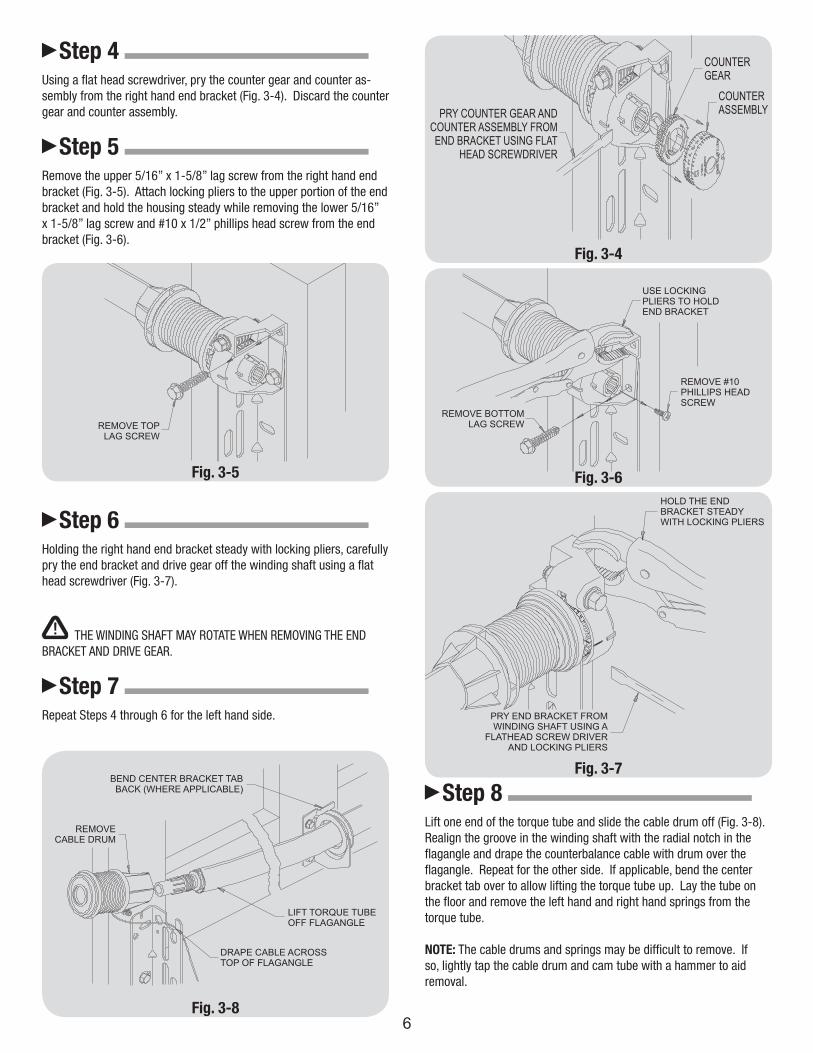
Step 4 Using a flat head screwdriver, pry the counter gear and counter as-sembly from the right hand end bracket (Fig. 3-4). Discard the counter gear and counter assembly.
Step 5 Remove the upper 5/16” x 1-5/8” lag screw from the right hand end bracket (Fig. 3-5). Attach locking pliers to the upper portion of the end bracket and hold the housing steady while removing the lower 5/16” x 1-5/8” lag screw and #10 x 1/2” phillips head screw from the end bracket (Fig. 3-6).
Step 6 Holding the right hand end bracket steady with locking pliers, carefully pry the end bracket and drive gear off the winding shaft using a flat head screwdriver (Fig. 3-7).
CAUTIONTHE WINDING SHAFT MAY ROTATE WHEN REMOVING THE END
BRACKET AND DRIVE GEAR.
Step 7 Repeat Steps 4 through 6 for the left hand side.
Fig. 3-4
Fig. 3-5 Fig. 3-6
Fig. 3-7
Step 8 Lift one end of the torque tube and slide the cable drum off (Fig. 3-8). Realign the groove in the winding shaft with the radial notch in the flagangle and drape the counterbalance cable with drum over the flagangle. Repeat for the other side. If applicable, bend the center bracket tab over to allow lifting the torque tube up. Lay the tube on the floor and remove the left hand and right hand springs from the torque tube.
NOTE: The cable drums and springs may be difficult to remove. If so, lightly tap the cable drum and cam tube with a hammer to aid removal.
Fig. 3-86

7
Re-installation Instructions forTorqueMaster™ Single Spring System
The TorqueMaster™ Single Spring counterbalance system is applicable for door weights equal to 115 pounds and below. The single spring will always be to the right hand side.
Step 1 Slide the right hand spring, perch end first, into the torque tube (Fig. 4-1). Lift the spring tube assembly up and align the center bushing into the center bracket. Push the right cable drum over the winding shaft until seated against the spring tube assembly and the winding shaft groove is exposed. Align the groove in the winding shaft with the radial notch on the flagangle (Fig. 4-2). Insert the left winding shaft into the left cable drum until the winding shaft groove is exposed. Push the left cable drum on until seated against the spring tube assembly and align the winding shaft groove with the radial notch on the flagangle (Fig. 4-2).
IMPORTANT! RIGHT AND LEFT HAND IS ALWAYS DETERMINED FROM INSIDE THE BUILDING LOOKING OUT.
Step 2 Check the torque tube for level and adjust if necessary (Fig. 4-3). If applicable, bend the center bracket tab back over the center bushing.
Step 3 Apply lubricant to the entire circumference of the drive gear. Align the splines of the drive gear with the right hand winding shaft and press the gear on until seated against the flagangle (Fig 4-4). Slide the right hand end bracket over the drive gear and fasten to the flagangle using a #10 x 1/2” phillips head screw. Attach the end bracket to the jamb using (2) 5/16” x 1-5/8” lag screws (Fig. 4-5).
Fig. 4-1
Fig. 4-2
Fig. 4-3
Fig. 4-4

8
Fig. 4-5
Step 4 Slide the left hand end bracket over the winding shaft and fasten to the flagangle using a #10 x 1/2” phillips head screw. Attach the end bracket to the jamb using (2) 5/16” x 1-5/8” lag screws (Fig. 4-5). No drive gear is required for the left hand side. If converting from a double spring to single spring system, remove the winding bolt head, flanged bearing, worm gear and lock nut from the left hand end bracket assembly. These components are not required and can be discarded.
IMPORTANT! WARNING TAGS MUST BE SECURELY ATTACHED TO BOTH END BRACKETS.
Step 5 Install the counter gear with the missing tooth towards the outside, away from the right hand end bracket (Fig. 4-6). Press the counter gear onto the cylinder until the snaps engage. Align the number “0” on the right hand counter cover assembly with the raised rib on the right hand end bracket and align the hex of the counter cam with the winding shaft. Press the counter assembly against the counter gear until it locks into place.
NOTE: No counter gear or counter cover assembly is required for the left hand side.
Step 6 Adjust the right hand counterbalance cable by rotating the cable drum until the set screw faces directly away from the header (Fig. 4-7). Check to ensure the cable is aligned and seated in the first groove of the cable drum and that cable tension is taut. If cable tension is slack, loosen the set screw and pull on the end of cable to remove all slack. Snug the set screw, then tighten an additional 1 to 1-1/2 turns.
Clamp locking pliers onto both vertical tracks just above the third roller. This is to prevent the door from raising while winding the right hand spring.
WARNINGFAILURE TO CLAMP TRACK CAN ALLOW THE DOOR TO RAISE AND
CAUSE SEVERE INJURY OR DEATH.
Fig. 4-6
Fig. 4-7

Step 7 Using an electric drill (High torque / gear reduced to 1300 rpm preferred) with a 7/16” hex head driver, carefully rotate the right hand winding bolt head clockwise while pressing in on the canoe clip, until the counter cover assembly shows 2 to 3 turns (Fig. 4-8). This will keep the counterbalance cable taut while adjusting the left side counterbalance cable.
DO NOT USE IMPACT GUN TO WIND SPRINGS!!
Step 8 Check to ensure the left hand counterbalance cable is aligned and seated in the first groove of the cable drum and that cable tension is taut (Fig. 4-7). If cable tension is slack, loosen the set screw and pull on the end of cable to remove all slack. Snug the set screw, then tighten an additional 1 to 1-1/2 turns.
IMPORTANT! MAKE SURE THE COUNTERBALANCE CABLES ARE ALIGNED IN THE FIRST GROOVE OF THE CABLE DRUM AND THAT CABLE TENSION IS EQUAL FOR BOTH SIDES.
Step 9 Return to the right hand side and continue rotating the winding bolt head clockwise (Fig. 4-8), until the counter cover assembly shows the correct number of turns for your door height.
6’-0” Door Height = 14 turns6’-3” Door Height = 14 1/2 turns6’-6” Door Height = 15 turns6’-9” Door Height = 15 1/2 turns7’-0” Door Height = 16 turns7’-3” Door Height = 16 1/2 turns7’-6” Door Height = 17 turns7’-9” Door Height = 17 1/2 turns8’-0” Door Height = 18 turns
CAUTIONDO NOT USE IMPACT GUN TO WIND SPRINGS!!
After the right hand spring is correctly wound, hold the lock nut stationary with a 7/16” wrench while rotating the winding bolt head clockwise until snug (Fig. 4-8). Tightening of the lock nut prevents the spring from unwinding.
9
Fig. 4-8
Step 10 Remove locking pliers from the vertical track and cautiously lift the door and check it’s balance. If door is hard to pull down or lifts by itself, loosen the lock nut on the right hand winding bolt and adjust the spring tension by rotating counterclockwise 4 revolutions (ap-proximately 1/4 spring turn). If door is difficult to lift or too easy to pull down, adjust the spring tension by rotating the winding bolt head clockwise 4 revolutions. Recheck the door balance and repeat if necessary. When finished, retighten the lock nut on the winding bolt head.
IMPORTANT! DO NOT ADD OR REMOVE MORE THAN 1 SPRING TURN FROM THE SPECIFIED AMOUNT.
If door still does not operate easily, lower the door into the closed position, UNWIND THE RIGHT HAND SPRING TO ZERO, and recheck the following items:1.) Check the door for level.2.) Check the TorqueMaster™ torque tube and flagangles for level.3.) Check the distance between the flagangles - must be door width plus 3-3/8”, + 1/4”, - 0”.4.) Check the counterbalance cables for equal tension - loosen set screws and adjust if necessary.5.) Rewind the right hand spring.

10
Reinstallation Instructions forTorqueMaster™ Double Spring System
The TorqueMaster™ Double Spring counterbalance system is appli-cable for door weights greater than 115 lbs.
Step 1 Slide the right and left hand springs, perch end first, into the torque tube (Fig. 5-1) . Lift the spring tube assembly up and align the center bushing into the center bracket. Push the right cable drum over the winding shaft until seated against the spring tube assembly and the winding shaft groove is exposed. Align the groove in the winding shaft with the radial notch on the flagangle (Fig. 5-2). Push the left cable drum on until seated against the spring tube assembly and align the winding shaft groove with the radial notch on the flagangle.
IMPORTANT! RIGHT AND LEFT HAND IS ALWAYS DETERMINED FROM INSIDE THE BUILDING LOOKING OUT.
Step 2 Check the torque tube for level and adjust if necessary (Fig. 5-3). If applicable, bend the center bracket tab back over the center bushing.
Fig. 5-1
Fig. 5-2
Fig. 5-3
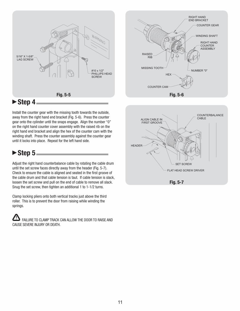
Step 3 Apply lubricant to the entire circumference of the drive gear. Align the splines of the drive gear with the right hand winding shaft and press the gear on until seated against the flagangle (Fig 5-4). Slide the right hand end bracket over the drive gear and fasten to the flagangle using a #10 x 1/2” phillips head screw. Attach the end bracket to the jamb using (2) 5/16” x 1-5/8” lag screws (Fig. 5-5). Repeat for the left hand side.
IMPORTANT! WARNING TAGS MUST BE SECURELY ATTACHED TO BOTH END BRACKETS. Fig. 5-4
11
Fig. 5-5
Step 4
Install the counter gear with the missing tooth towards the outside, away from the right hand end bracket (Fig. 5-6). Press the counter gear onto the cylinder until the snaps engage. Align the number “0” on the right hand counter cover assembly with the raised rib on the right hand end bracket and align the hex of the counter cam with the winding shaft. Press the counter assembly against the counter gear until it locks into place. Repeat for the left hand side.
Step 5
Adjust the right hand counterbalance cable by rotating the cable drum until the set screw faces directly away from the header (Fig. 5-7). Check to ensure the cable is aligned and seated in the first groove of the cable drum and that cable tension is taut. If cable tension is slack, loosen the set screw and pull on the end of cable to remove all slack. Snug the set screw, then tighten an additional 1 to 1-1/2 turns.
Clamp locking pliers onto both vertical tracks just above the third roller. This is to prevent the door from raising while winding the springs.
WARNINGFAILURE TO CLAMP TRACK CAN ALLOW THE DOOR TO RAISE AND
CAUSE SEVERE INJURY OR DEATH.
Fig. 5-6
Fig. 5-7

12
Step 6 Using an electric drill (High torque / gear reduced to 1300 rpm preferred) with a 7/16” hex head driver, carefully rotate the right hand winding bolt head clockwise while pressing in on the canoe clip, until the counter cover assembly shows 2 to 3 turns (Fig. 5-8). This will keep the counterbalance cable taut while winding the left side.
DO NOT USE IMPACT GUN TO WIND SPRINGS!!
Step 7 Check to ensure the left hand counterbalance cable is aligned and seated in the first groove of the cable drum and that cable tension is taut (Fig. 5-7). If cable tension is slack, loosen the set screw and pull on the end of cable to remove all slack. Snug the set screw, then tighten an additional 1 to 1-1/2 turns.
IMPORTANT! MAKE SURE THE COUNTERBALANCE CABLES ARE ALIGNED IN THE FIRST GROOVE OF THE CABLE DRUM AND THAT CABLE TENSION IS EQUAL FOR BOTH SIDES.
Step 8 Carefully rotate the left hand winding bolt head clockwise (Fig. 5-8), until the counter cover assembly shows the correct number of turns for your door height.
6’-0” Door Height = 14 turns6’-3” Door Height = 14 1/2 turns6’-6” Door Height = 15 turns6’-9” Door Height = 15 1/2 turns7’-0” Door Height = 16 turns7’-3” Door Height = 16 1/2 turns7’-6” Door Height = 17 turns7’-9” Door Height = 17 1/2 turns8’-0” Door Height = 18 turns
DO NOT USE IMPACT GUN TO WIND SPRINGS!!
Return to the right hand spring and continue winding it until the cor-rect number of turns is reached. After the both springs are correctly wound, hold the lock nut stationary with a 7/16” wrench while rotating the winding bolt head clockwise until snug (Fig. 5-8). Tightening of the lock nuts prevents the springs from unwinding.
Fig. 5-8
Step 9 Remove locking pliers from the vertical track and cautiously lift the door and check it’s balance. If door is hard to pull down or lifts by itself, adjust the spring tension by rotating the winding bolt head coun-terclockwise 4 revolutions (approximately 1/4 spring turn). If door is difficult to lift or too easy to pull down, adjust the spring tension by rotating the winding bolt head clockwise 4 revolutions. Anytime spring adjustments are made, the lock nuts must be loosen to begin with and retighten afterwards. Adjust both springs equally. Recheck the door balance and repeat if necessary.
IMPORTANT! DO NOT ADD OR REMOVE MORE THAN 1 SPRING TURN FROM THE SPECIFIED AMOUNT.
If door still does not operate easily, lower the door into the closed position, UNWIND BOTH SPRINGS TO ZERO, and recheck the following items:
1.) Check the door for level.
2.) Check the TorqueMaster™ torque tube and flagangles for level.
3.) Check the distance between the flagangles - must be door width plus 3-3/8”, + 1/4”, - 0”.
4.) Check the counterbalance cables for equal tension - loosen set screws and adjust if necessary.
5.) Rewind both springs.