Torque and power limitations of a shunt connected inverter ... · Torque and power limitations of a...
7
Torque and power limitations of a shunt connected inverter based WECS ALON KUPERMAN*, RAUL RABINOVICI*, GEORGE WEISS** *Electrical and Computer Engineering Department **Electrical Engineering Department Ben-Gurion University of the Negev Imperial College Beer-Sheva London ISRAEL UK Abstract: - A variable speed wind energy conversion system based on a squirrel cage autonomous induction generated is covered in this paper for operation in high wind speeds. In this case, the turbine must limit the fraction of the wind power captured so that safe electrical and mechanical loads are not exceeded. Different control strategies based on induction machine characteristics for fixed-pitch turbines are discussed. Extended simulation results are presented for main control approaches. Key-Words: Renewable energy, variable speed, power and torque control, wind turbine, induction generator. 1 Introduction Over the past two decades, a great deal of effort was made to develop different types of wind energy conversion systems (WECS). Wind is one of the fastest growing sources of alternative power in the world today. WECS present two operating modes, according to the way the wind turbine is connected to the grid. In the first, fixed-speed mode, the turbine-generator unit is directly connected to the grid, fixing the generator rotational speed to be around the grid frequency. In the second, variable speed mode, power converters are inserted between the generator and the greed, allowing the rotational speed and electrical frequency to vary independently. Usually the regulation objectives rely on the wind speed. Variable speed wind turbines have three main operation regions. First region includes the turbine starting-up. In low and medium speeds, the objection is to capture as much energy as possible (region two) [1, 2]. Since the power electronics circuitry is able to control the generator output, variable speed mode is useful in this operating region. When the power or speed limit of a wind turbine is reached, they should be limited in order to prevent the generator and turbine overloading. This happens at high wind speeds [3]. This is the region three. This paper focuses on this region. Limitation of the power output in high winds in necessary on all wind turbines, otherwise the turbine will be overloaded. The usual methods for power limitation are stall regulation or pitch regulation. On turbines with normal stall regulation, the blades are rigidly fixed to the turbine hub and cannot be turned around their longitudinal axis during operation. The pitch setting angle between blades and hub is adjusted during commissioning of the turbine. It may require fine-tuning for site-specific conditions. Stall regulated blades are designed so the airflow over the blades themselves causes higher drag in high winds and thereby automatically restricts the power output. By this passive use of the aerodynamic characteristics of the blades, the power regulation is simple and rugged under all conditions. The peak loads in high wind are moderate. On the other hand, normal stall regulation has the disadvantage that the maximum power output may depend on the air density and on the surface roughness of the blades. Therefore, changes in the maximum power output may occur from summer to winter and dirty blades may cause the peak power to drop. On pitch regulated turbines, the blades are mounted on the rotor hub with turntable bearings. They can be turned around their longitudinal axis during operation. In high winds the pitch setting of the blades is continuously adjusted away from stall point, reducing the blade lift to yield precisely the maximum power specified. This requires a rather complicated active regulation system, which can be sensitive towards turbulence in high winds. Therefore, pitch regulation in practice requires a special generator with fully or partially variable speed, allowing for a slight acceleration in rotor speed at wind gusts. Otherwise, the active regulation is unable to follow the variations of the wind and excessive peak loads will occur [4]. The combination of stall Proceedings of the 5th WSEAS Int. Conf. on Power Systems and Electromagnetic Compatibility, Corfu, Greece, August 23-25, 2005 (pp383-389)
Transcript of Torque and power limitations of a shunt connected inverter ... · Torque and power limitations of a...

Torque and power limitations of a shunt connected inverter based WECS
ALON KUPERMAN*, RAUL RABINOVICI*, GEORGE WEISS**
*Electrical and Computer Engineering Department **Electrical Engineering Department Ben-Gurion University of the Negev Imperial College Beer-Sheva London ISRAEL UK
Abstract: - A variable speed wind energy conversion system based on a squirrel cage autonomous induction generated is covered in this paper for operation in high wind speeds. In this case, the turbine must limit the fraction of the wind power captured so that safe electrical and mechanical loads are not exceeded. Different control strategies based on induction machine characteristics for fixed-pitch turbines are discussed. Extended simulation results are presented for main control approaches.
Key-Words: Renewable energy, variable speed, power and torque control, wind turbine, induction generator.
1 Introduction Over the past two decades, a great deal of effort was made to develop different types of wind energy conversion systems (WECS). Wind is one of the fastest growing sources of alternative power in the world today. WECS present two operating modes, according to the way the wind turbine is connected to the grid. In the first, fixed-speed mode, the turbine-generator unit is directly connected to the grid, fixing the generator rotational speed to be around the grid frequency. In the second, variable speed mode, power converters are inserted between the generator and the greed, allowing the rotational speed and electrical frequency to vary independently. Usually the regulation objectives rely on the wind speed. Variable speed wind turbines have three main operation regions. First region includes the turbine starting-up. In low and medium speeds, the objection is to capture as much energy as possible (region two) [1, 2]. Since the power electronics circuitry is able to control the generator output, variable speed mode is useful in this operating region. When the power or speed limit of a wind turbine is reached, they should be limited in order to prevent the generator and turbine overloading. This happens at high wind speeds [3]. This is the region three. This paper focuses on this region.
Limitation of the power output in high winds in necessary on all wind turbines, otherwise the turbine will be overloaded. The usual methods for power limitation are stall regulation or pitch regulation. On
turbines with normal stall regulation, the blades are rigidly fixed to the turbine hub and cannot be turned around their longitudinal axis during operation. The pitch setting angle between blades and hub is adjusted during commissioning of the turbine. It may require fine-tuning for site-specific conditions. Stall regulated blades are designed so the airflow over the blades themselves causes higher drag in high winds and thereby automatically restricts the power output. By this passive use of the aerodynamic characteristics of the blades, the power regulation is simple and rugged under all conditions. The peak loads in high wind are moderate. On the other hand, normal stall regulation has the disadvantage that the maximum power output may depend on the air density and on the surface roughness of the blades. Therefore, changes in the maximum power output may occur from summer to winter and dirty blades may cause the peak power to drop. On pitch regulated turbines, the blades are mounted on the rotor hub with turntable bearings. They can be turned around their longitudinal axis during operation. In high winds the pitch setting of the blades is continuously adjusted away from stall point, reducing the blade lift to yield precisely the maximum power specified. This requires a rather complicated active regulation system, which can be sensitive towards turbulence in high winds. Therefore, pitch regulation in practice requires a special generator with fully or partially variable speed, allowing for a slight acceleration in rotor speed at wind gusts. Otherwise, the active regulation is unable to follow the variations of the wind and excessive peak loads will occur [4]. The combination of stall
Proceedings of the 5th WSEAS Int. Conf. on Power Systems and Electromagnetic Compatibility, Corfu, Greece, August 23-25, 2005 (pp383-389)
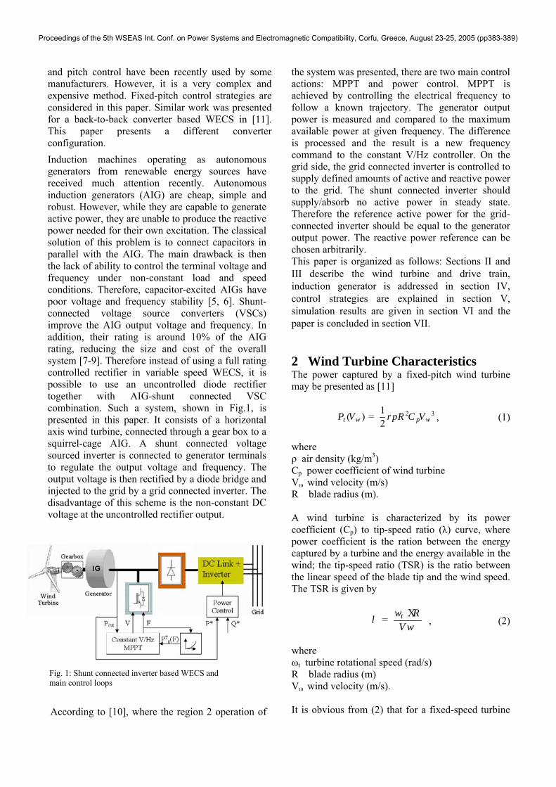
and pitch control have been recently used by some manufacturers. However, it is a very complex and expensive method. Fixed-pitch control strategies are considered in this paper. Similar work was presented for a back-to-back converter based WECS in [11]. This paper presents a different converter configuration. Induction machines operating as autonomous generators from renewable energy sources have received much attention recently. Autonomous induction generators (AIG) are cheap, simple and robust. However, while they are capable to generate active power, they are unable to produce the reactive power needed for their own excitation. The classical solution of this problem is to connect capacitors in parallel with the AIG. The main drawback is then the lack of ability to control the terminal voltage and frequency under non-constant load and speed conditions. Therefore, capacitor-excited AIGs have poor voltage and frequency stability [5, 6]. Shunt-connected voltage source converters (VSCs) improve the AIG output voltage and frequency. In addition, their rating is around 10% of the AIG rating, reducing the size and cost of the overall system [7-9]. Therefore instead of using a full rating controlled rectifier in variable speed WECS, it is possible to use an uncontrolled diode rectifier together with AIG-shunt connected VSC combination. Such a system, shown in Fig.1, is presented in this paper. It consists of a horizontal axis wind turbine, connected through a gear box to a squirrel-cage AIG. A shunt connected voltage sourced inverter is connected to generator terminals to regulate the output voltage and frequency. The output voltage is then rectified by a diode bridge and injected to the grid by a grid connected inverter. The disadvantage of this scheme is the non-constant DC voltage at the uncontrolled rectifier output.
According to [10], where the region 2 operation of
the system was presented, there are two main control actions: MPPT and power control. MPPT is achieved by controlling the electrical frequency to follow a known trajectory. The generator output power is measured and compared to the maximum available power at given frequency. The difference is processed and the result is a new frequency command to the constant V/Hz controller. On the grid side, the grid connected inverter is controlled to supply defined amounts of active and reactive power to the grid. The shunt connected inverter should supply/absorb no active power in steady state. Therefore the reference active power for the grid-connected inverter should be equal to the generator output power. The reactive power reference can be chosen arbitrarily. This paper is organized as follows: Sections II and III describe the wind turbine and drive train, induction generator is addressed in section IV, control strategies are explained in section V, simulation results are given in section VI and the paper is concluded in section VII.
2 Wind Turbine Characteristics The power captured by a fixed-pitch wind turbine may be presented as [11]
2 31( )2t w p wP V R C Vr p= , (1)
where ρ air density (kg/m3) Cp power coefficient of wind turbine Vω wind velocity (m/s) R blade radius (m). A wind turbine is characterized by its power coefficient (Cp) to tip-speed ratio (λ) curve, where power coefficient is the ration between the energy captured by a turbine and the energy available in the wind; the tip-speed ratio (TSR) is the ratio between the linear speed of the blade tip and the wind speed. The TSR is given by
t RV w
wl Χ= , (2)
where ωt turbine rotational speed (rad/s) R blade radius (m) Vω wind velocity (m/s). It is obvious from (2) that for a fixed-speed turbine
Fig. 1: Shunt connected inverter based WECS and main control loops
Proceedings of the 5th WSEAS Int. Conf. on Power Systems and Electromagnetic Compatibility, Corfu, Greece, August 23-25, 2005 (pp383-389)
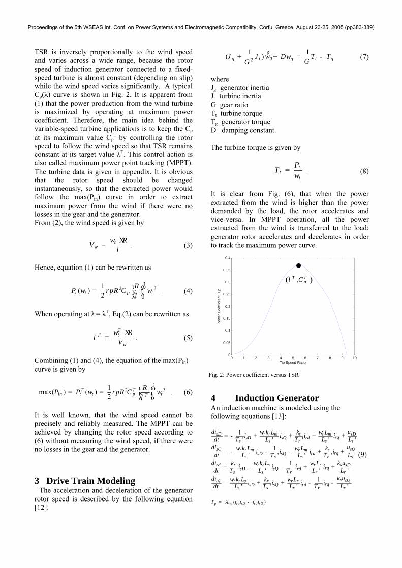
TSR is inversely proportionally to the wind speed and varies across a wide range, because the rotor speed of induction generator connected to a fixed-speed turbine is almost constant (depending on slip) while the wind speed varies significantly. A typical Cp(λ) curve is shown in Fig. 2. It is apparent from (1) that the power production from the wind turbine is maximized by operating at maximum power coefficient. Therefore, the main idea behind the variable-speed turbine applications is to keep the Cp at its maximum value Cp
T by controlling the rotor speed to follow the wind speed so that TSR remains constant at its target value λT. This control action is also called maximum power point tracking (MPPT). The turbine data is given in appendix. It is obvious that the rotor speed should be changed instantaneously, so that the extracted power would follow the max(Pin) curve in order to extract maximum power from the wind if there were no losses in the gear and the generator. From (2), the wind speed is given by
tw
RV wlΧ= . (3)
Hence, equation (1) can be rewritten as
32 31( )
2t t p tRP R Cw r p wlι ω= κ ϊλ ϋ
. (4)
When operating at λ = λT, Eq.(2) can be rewritten as
TtT
w
RV
wl Χ= . (5)
Combining (1) and (4), the equation of the max(Pin) curve is given by
32 31max( ) ( )
2T T
in t t p tTRP P R Cw rp w
lι ω= = κ ϊλ ϋ
. (6)
It is well known, that the wind speed cannot be precisely and reliably measured. The MPPT can be achieved by changing the rotor speed according to (6) without measuring the wind speed, if there were no losses in the gear and the generator. 3 Drive Train Modeling
The acceleration and deceleration of the generator rotor speed is described by the following equation [12]:
21 1( ) gg t g t gJ J D T T
GGw w+ + = -g
(7)
where Jg generator inertia Jt turbine inertia G gear ratio Tt turbine torque Tg generator torque D damping constant. The turbine torque is given by
tt
t
PTw
= . (8)
It is clear from Fig. (6), that when the power extracted from the wind is higher than the power demanded by the load, the rotor accelerates and vice-versa. In MPPT operation, all the power extracted from the wind is transferred to the load; generator rotor accelerates and decelerates in order to track the maximum power curve.
0 1 2 3 4 5 6 7 8 9 100
0.05
0.1
0.15
0.2
0.25
0.3
0.35
0.4
Pow
er C
oeffi
cien
t, C
p
Tip-Speed Ratio
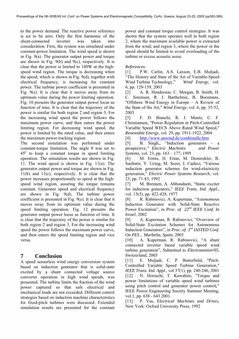
4 Induction Generator An induction machine is modeled using the following equations [13]:
1' ' ' ' '
1' ' ' ' '
1' ' ' ' '
' '
r r m s r msD sDrqsD sQ rd
s s r s s
sQ sQr r m r m srqsD sQ rd
s s s r s
sr r r s r rrd sDrqsD sQ rd
s s r r r
rq r r s r r rsD sQ
s s
di uk L k Li i i idt T L T L Ldi uk L L ki i i idt L T L T Ldi k uk k L Li i i idt T L T L Ldi k L k Li idt L T L
w w
w w
w w
w w
= - + + + +
= - - - + +
= - - + +
= + +
3 ( )
1' ' '
g m rq sD rd sQ
s sQrqrd
r r r
T L i i i i
k ui iT L
= -
- -
)9(
( ),T TpCl
Fig. 2: Power coefficient versus TSR
Proceedings of the 5th WSEAS Int. Conf. on Power Systems and Electromagnetic Compatibility, Corfu, Greece, August 23-25, 2005 (pp383-389)

where
2
2
1
1
'
'
r
s r m
r
s r m
s
s ms
mr
s
r
L L LL
L L LL
L L LL L L
L
L
= +
= +
-
-
=
=
'
'
'
'
ms
s
mr
r
ss
s
rr
r
R
R
Lk LLk LLT
LT
=
=
=
=
,sD sDi i - instantaneous values of direct- and quadrature- axis stator current components respectively and expressed in the stationary reference frame
,rD rDi i - instantaneous values of direct- and quadrature- axis rotor current components respectively and expressed in the stationary reference frame
1,s sL L - self- and leakage inductances of the stator respectively
1,r rL L - self- and leakage inductances of the rotor respectively
mL - magnetizing inductance ', 's rT T - stator and rotor transient time constants
respectively ,sD sDu u - instantaneous values of direct- and
quadrature- axis stator voltage components respectively and expressed in the stationary reference frame
rw - angular rotor speed Magnetizing reactance mL is shown in Fig. 3.
5 Control Strategies It was shown in [10], that instead of monitoring the rotational speed, it is possible to monitor the electrical frequency (which is known from constant V/Hz controller) in order to perform MPPT. It should be noted, that there is a minimum value of
electrical frequency Fmin that should be maintained in order to keep the power flow unidirectional (generator operation only). Generator output power versus electrical frequency curves for different wind speeds are shown in Fig. 4. Maximum power curve can also be computed for optimal power capture in region 2. Therefore measuring the wind speed, rotor speed or the electrical frequency are equivalent actions. Induction machine external speed-power characteristics and possible output power curves at different wind speeds are shown in Fig.5. Any point under the machine characteristic curve is possible; any point above the curve can damage the machine and should be avoided and in presence of high wind speeds power limitation should be performed.
0.4 0.6 0.8 1 1.2 1.4 1.6 1.80
10
20
30
40
50
60
70
80
Per unit frequency, F
Per
pha
se p
ower
[W]
max ( Pout )
Vw = 12 m/s
Vw = 11 m/s
Vw = 10 m/s
Vw = 9 m/s
Vw = 8 m/s
Fmin
In addition, speed limitation should be also considered mainly because of two reasons. First, a certain level of acoustic noise should not be reached. Second, physical limitations of turbine and generator rotational speed exist and must be taken into
Fig. 3: Measured magnetizing reactance
Fig. 4: Generator per phase output power versus electrical frequency
Fig. 5: Generator output power characteristics
Proceedings of the 5th WSEAS Int. Conf. on Power Systems and Electromagnetic Compatibility, Corfu, Greece, August 23-25, 2005 (pp383-389)

account. However, power limitation is mainly considered, because the system usually reaches power limit when the speed is still in the permissible range [14,15]. Consider a generator with output power curves at different speeds as shown in Fig. 6. At normal wind speeds, generator output power should track the max(Pout) curve to extract maximum power from the wind. At high wind speeds, different scenarios can occur. If the upper speed limit (vmax1) is reached before the power limit, from point A the system no longer follows the maximum power curve. The electrical frequency is kept constant by the constant V/f controller; therefore the rotation speed can only grow slightly with the slip. If the wind speed increases, we move up from point A to point B, where the power limit is met. If the wind speed further increases, the output power should be kept constant. Because the speed limit is also reached, the only way to keep the power at its rated value is to move left from the point B along the Pmax curve, by decreasing the rotation speed and electrical frequency. The main drawback of this strategy is the torque behavior.
0.2 0.4 0.6 0.8 1 1.2 1.4 1.6 1.8 20
20
40
60
80
100
120
Per unit speed, v
Per
pha
se p
ower
[W]
max ( Pout )
A
B
C
D
Pmax
v max 1 v max 2
The torque, which is given by the ration between power and speed, increases if the power is kept constant and the speed decreases and there is a danger of excessive torque. If the power limit is reached before the upper speed limit (vmax2), the max(Pout) curve is followed by the system up to point C, where the rated power is reached. If the wind speed is further increasing, the system can move on the max(Pout) line either left or right to point D. The movement to the left is characterized by increased torque, while movement to the right causes the torque to decrease, as shown in Fig. 7. Usually, if the acoustic noise is out of concern, the maximum allowable speed is around
twice the rated speed, therefore movement to the right is preferable to evade the excess torque possibility. Sometimes, if the maximum rotational speed limit is somewhat flexible, instead of following the AB part of the target power curve (Fig.6), the system follows the AB' curve of Fig. 8, which is not strictly vertical, i.e. the angle θ is less then 90o. Using this strategy, disadvantages of near-rated fixed speed, like severe torque and output surge with wind turbulence, are avoided [16]. Therefore setting the angle θ to 0o we gain constant electrical output; setting the angle θ to 45o we gain a constant torque operation (constant power to speed ratio), which is a very desirable feature.
0.2 0.4 0.6 0.8 1 1.2 1.4 1.6 1.8 20
20
40
60
80
100
120
Per unit speed, v
Per
pha
se p
ower
[W]
Constant Power
C
Increasing Torque
Decreasing Torque
0.2 0.4 0.6 0.8 1 1.2 1.4 1.6 1.8 20
20
40
60
80
100
120
Per unit speed, v
Per
pha
se p
ower
[W]
A
BB*
6 Simulation Results and Discussion The presented system was modeled and simulated using MATLAB ® and SIMULINK ® packages [17]. DC link and grid-connected inverter where represented by a variable resistance. The resistance value is changed by the power controller according
Fig. 6: Different scenarios for speed and power
Fig. 7: Torque behavior for different power limitation strategies
Fig. 8: Constant torque limitation strategy
Proceedings of the 5th WSEAS Int. Conf. on Power Systems and Electromagnetic Compatibility, Corfu, Greece, August 23-25, 2005 (pp383-389)
to the power demand. The reactive power reference is set to be zero. Only the first harmonic of the shunt-connected inverter was taken into consideration. First, the system was simulated under constant-power limitation. The wind speed is shown in Fig. 9(a). The generator output power and torque are shown in Fig. 9(b) and 9(c), respectively. It is clear that the power is limited to 180W at the high-speed wind region. The torque is decreasing when the speed, which is shown in Fig. 9(d), together with electrical frequency, is increasing for constant power. The turbine power coefficient is presented in Fig. 9(e). It is clear that it moves away from its optimum value during the power limiting operation. Fig. 10 presents the generator output power locus as function of time. It is clear that the trajectory of the power is similar for both region 2 and region 3. For the increasing wind speed the power follows the maximum power curve, and then enters the power limiting region. For decreasing wind speed, the power is limited by the rated value, and then enters the maximum power tracking region. The second simulation was performed under constant-torque limitation. The angle θ was set to 45o to keep a constant torque in speed limiting operation. The simulation results are shown in Fig. 11. The wind speed is shown in Fig. 11(a). The generator output power and torque are shown in Fig. 11(b) and 11(c), respectively. It is clear that the power increases proportionally to speed at the high-speed wind region, assuring the torque remains constant. Generator speed and electrical frequency are shown in Fig. 9(d). The turbine power coefficient is presented in Fig. 9(e). It is clear that it moves away from its optimum value during the speed limiting operation. Fig. 12 presents the generator output power locus as function of time. It is clear that the trajectory of the power is similar for both region 2 and region 3. For the increasing wind speed the power follows the maximum power curve, and then enters the speed limiting region and vice versa.
7 Conclusion A speed sensorless wind energy conversion system based on induction generator that is solid-state excited by a shunt connected voltage source converter operation in high wind speeds, was presented. The turbine limits the fraction of the wind power captured so that safe electrical and mechanical loads are not exceeded. Different control strategies based on induction machine characteristics for fixed-pitch turbines were discussed. Extended simulation results are presented for the constant
power and constant torque control strategies. It was shown that the system operates well in both region 2, where the maximum available power is extracted from the wind; and region 3, where the power or the speed should be limited to avoid overloading of the turbine or excess acoustic noise. References: [1] P.W. Carlin, A.S. Laxson, E.B. Muljadi, “The History and State of the Art of Variable-Speed Wind Turbine Technology,” Wind Energy, vol. 6, pp. 129-159, 2003 [2] A. R. Henderson, C. Morgan, B. Smith, H. C. Sorensen, R. J. Barthelmie, B. Boesmans, "Offshore Wind Energy in Europe – A Review of the State of the Art," Wind Energy, vol. 6, pp. 35-52, 2003 [3] F. D. Bianchi, R. J. Mantz, C. F. Christiansen, "Power Regulation in Pitch-Controlled Variable Speed WECS Above Rated Wind Speed," Renewable Energy, vol. 29, pp. 1911-1922, 2004 [4] http://www.anwind.de/combistalle.htm [5] B. Singh,, “Induction generators – a prospective,” Electric Machines and Power Systems, vol. 23, pp. 163 – 177, 1995 [6] M. Ermis, H. Ertan, M. Demirekler, B. Saribatir, Y. Uctug, M. Sezer, I. Cadirci, “Various induction generator schemes for wind-electricity generation,” Electric Power Systems Research, vol. 23, pp. 71-83, 1992 [7] M. Brennen, A. Abbondanti, “Static exciter for induction generators,” IEEE Trans. Ind. Appl., vol. 13(5), pp. 422-428, 1977 [8] R. Rabinovici, A. Kuperman, “Autonomous Induction Generator with Solid-State Reactive Power Excitation”, in Proc. of 22nd IEEE Conf. In Israel, 2002 [9] A. Kuperman, R. Rabinovici, “Overview of Solid-State Excitation Schemes for Autonomous Induction Generators”, in Proc. of 3rd IASTED Conf. On PES , Marbella, Spain, 2003 [10] A. Kuperman, R. Rabinovici, “A shunt connected inverter based variable speed wind turbine generation”, Submitted to Electromotion'05, Switzerland, 2005 [11] E. Muljadi, C. P. Butterfield, "Pitch-Controlled Variable Speed Turbine Generation," IEEE Trans. Ind. Appl., vol 37(1), pp. 240-246, 2001 [12] N. Horiuchi, T. Kawahito, "Torque and power limitations of variable speed wind turbines using pitch control and generator power control," IEEE Power Engineering Society Summer Meeting, vol.1, pp. 638 - 643 2001. [13] P. Vas, Electrical Machines and Drives, New York: Oxford University Press, 1992
Proceedings of the 5th WSEAS Int. Conf. on Power Systems and Electromagnetic Compatibility, Corfu, Greece, August 23-25, 2005 (pp383-389)

[14] A. Miller, E. Muljadi, D.S. Zinger, "A variable speed wind turbine power control," IEEE Trans. Energy Conv., vol. 12(2), pp. 181-186, 1997 [15] T. Thiringer, J. Linders, "Control by variable rotor speed of a fixed-pitch wind turbine operationg in a wide speed range," IEEE Trans. Energy Conv., vol. 8(3), pp. 520-526, 1993
0 10 20 30 40 50 60
10
15
Vw
, [m
/s]
0 10 20 30 40 50 600
100
200
Pg,
[W]
0 10 20 30 40 50 600
1
2
Tg, [
Nm
]
0 10 20 30 40 50 60
1
2
F
, v -
- , p
.u.
0 10 20 30 40 50 600
0.2
0.4
time, [sec]
Cp
0.8 1 1.2 1.4 1.6 1.8 2 2.20
20
40
60
80
100
120
140
160
180
200
Electrical Frequency, F p.u.
Gen
erat
or O
utpu
t Pow
er, P
g [W
]
[16] R. Cardenas, G.M. Asher, W.F. Ray, R. Pena, "Power limitation in variable speed wind turbines with fixed pitch angle," in Proc. of Opportunities and Advances in International Power Generation, pp. 44-48, 1996 [17] MATLAB User's Guide, Mathworks Inc., 2005
0 10 20 30 40 50 60
10
15
Vw
, [m
/s]
0 10 20 30 40 50 60-500
0
500
Pg,
[W]
0 10 20 30 40 50 600
1
2
Tg, [
Nm
]
0 10 20 30 40 50 600
1
2F
, v
- - p
.u.
0 10 20 30 40 50 600.2
0.3
0.4
time, [sec]
Cp
0.8 1 1.2 1.4 1.6 1.8 20
50
100
150
200
250
300
350
Electrical Frequencu, F p.u.
Gen
erat
or O
utpu
t Pow
er, P
g [W
]
Fig. 9: Simulation results - (a) wind speed, (b) generator output power, (c) generator torque, (d) generator speed (dashed) and electrical frequency (solid), (e) turbine power coefficient
Fig. 10: Generator output power locus
Fig. 11: Simulation results - (a) wind speed, (b) generator output power, (c) generator torque, (d) generator speed (dashed) and electrical frequency (solid), (e) turbine power coefficient
Fig. 12: Generator output power locus
Proceedings of the 5th WSEAS Int. Conf. on Power Systems and Electromagnetic Compatibility, Corfu, Greece, August 23-25, 2005 (pp383-389)