Torpedo - Taoglas · To fully realize the potential of these systems, a high-performance...
26
SPE-17-8-72-C Torpedo Part No: AQHA.11.A.101111 Description: Torpedo Permanent Mount GNSS L1 Antenna with 1m of RG-174 cable and SMA(M) connector Features: Permanent (Screw) Mount Antenna Quad-Helix – Optimized Radiation Pattern GPS/GLONASS/Galileo/BeiDou L1 Wide Input Voltage Range Dual-Stage LNA IP67 Rated, Robust ASA Enclosure Diameter 92.5mm, Height 120mm Cable: 1m RG-174 Connector: SMA (M) RoHS & Reach Compliant
Transcript of Torpedo - Taoglas · To fully realize the potential of these systems, a high-performance...

SPE-17-8-72-C
Torpedo
Part No:
AQHA.11.A.101111
Description:
Torpedo Permanent Mount GNSS L1 Antenna
with 1m of RG-174 cable and SMA(M) connector
Features:
Permanent (Screw) Mount Antenna
Quad-Helix – Optimized Radiation Pattern
GPS/GLONASS/Galileo/BeiDou L1
Wide Input Voltage Range
Dual-Stage LNA
IP67 Rated, Robust ASA Enclosure
Diameter 92.5mm, Height 120mm
Cable: 1m RG-174
Connector: SMA (M)
RoHS & Reach Compliant

2 SPE-17-8-072 -C www.taoglas.com
Taoglas makes no warranties based on the accuracy or completeness of the contents of this document and reserves the right to
make changes to specifications and product descriptions at any time without notice. Taoglas reserves all rights to this document and
the information contained herein. Reproduction, use or disclosure to third parties without express permission is strictly prohibited.
1. Introduction 3
2. Specifications 4
3. Antenna Characteristics 7
4. Radiation Patterns 10
5. LNA Characteristics 14
6. Mechanical Drawing 16
7. Packaging 17
8. Application Note 18
Changelog 23
3 SPE-17-8-072 -C www.taoglas.com
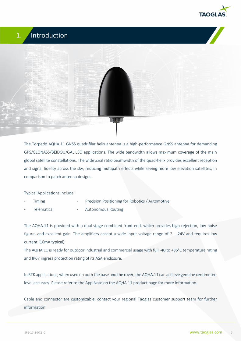
The Torpedo AQHA.11 GNSS quadrifilar helix antenna is a high-performance GNSS antenna for demanding
GPS/GLONASS/BEIDOU/GALILEO applications. The wide bandwidth allows maximum coverage of the main
global satellite constellations. The wide axial ratio beamwidth of the quad-helix provides excellent reception
and signal fidelity across the sky, reducing multipath effects while seeing more low elevation satellites, in
comparison to patch antenna designs.
Typical Applications Include:
- Timing - Precision Positioning for Robotics / Automotive
- Telematics - Autonomous Routing
The AQHA.11 is provided with a dual-stage combined front-end, which provides high rejection, low noise
figure, and excellent gain. The amplifiers accept a wide input voltage range of 2 – 24V and requires low
current (10mA typical).
The AQHA.11 is ready for outdoor industrial and commercial usage with full -40 to +85°C temperature rating
and IP67 ingress protection rating of its ASA enclosure.
In RTK applications, when used on both the base and the rover, the AQHA.11 can achieve genuine centimeter-
level accuracy. Please refer to the App Note on the AQHA.11 product page for more information.
Cable and connector are customizable, contact your regional Taoglas customer support team for further
information.
1. Introduction
1. Introduction
1. Introduction
1. Introduction
1. Introduction
1. Introduction
1. Introduction
1. Introduction

4 SPE-17-8-072 -C www.taoglas.com
GNSS Frequency Band
GPS/QZSS L1
1575.42MHz
L2
1227.6MHz
L5
1176.45MHz
L6
1278.75MHz
GLONASS L5R
1176.45MHz
L3PT
1201.5MHz
L2PT
1246MHz
L1CR
1575.42MHz
L1PT
1602MHz
Galileo E5a
1176.45MHz
E5b
1201.5MHz
E4
1215MHz
E3
1256MHz
E6
1278.75MHz
E2
1561MHz
L1
1575.42MHz
BeiDou B1
1561MHz
B2
1207.14MHz
B3
1268.52MHz
Compass E5B(B2)/ E6(B3)
1268.56MHz
E2(B1)
1561MHz
SBAS Omnistar
1542.5MHz
WAAS/EGN OS
1575.42MHz
2. Specifications
3. Antenna Characteristics2. Specifications
3. Antenna Characteristics
4. Antenna Radiation Patterns3. Antenna
Characteristics2. Specifications
3. Antenna Characteristics2. Specifications
3. Antenna Characteristics
4. Antenna Radiation Patterns3. Antenna
Characteristics
4. Antenna Radiation Patterns
4. Antenna Radiation Patterns3. Antenna
Characteristics
4. Antenna Radiation Patterns3. Antenna
Characteristics2. Specifications

5 SPE-17-8-072 -C www.taoglas.com
Electrical
Frequency BeiDou
1561 MHz
GPS
1575.42 MHz
GLONASS
1601.6 MHz
Efficiency (%) 70% 70% 70%
Peak Gain (dBi) +0.7 +1.0 +1.0
Axial Ratio Zenith to 90° elevation: < 3dB
Impedance 50 Ω
Polarization RHCP
Mechanical
Total Dimension 120*93Ø mm
Casing ASA
Base and thread Nickel Plated Zinc Alloy
Ingress Protection Rating IP67
Maximum Assembly Torque 39.2 N∙m
Weight 325 g
Cable/Connector RG174 coaxial cable, length 1000mm, SMA(M)
LNA Gain, Power Consumption and Noise Figure
BeiDou
1561 MHz
GPS
1575.42 MHz
GLONASS
1601.6 MHz
Input Voltage
2 – 24V
LNA Gain 28 dB 28 dB 28 dB
Noise Figure < 2.5 dB < 2.0 dB < 2.5 dB
In-band IP1dB > -20 dBm > -20 dBm > -20 dBm
Group Delay Variation
< 10 ns < 10 ns < 10 ns
Current < 15mA
Environmental
Operation Temperature -40°C to 85°C
Storage Temperature -40°C to 85°C
Humidity Non-condensing 65°C 95% RH
RoHS Compliant Yes
REACH Compliant Yes

6 SPE-17-8-072 -C www.taoglas.com
Field Test Result with 30*30cm ground plane
Frequency (MHz) GPS L1 Galileo E1 GLONASS G1 BeiDou B1I
1563-1587 1559-1591 1598-1605 1559-1563
Carrier-to-Noise Values(dB-Hz)
46.5 43 47.6 47.2
2*DRMS Positioning Accuracy (cm) without RTK
58 58 58 58
2*DRMS Positioning Accuracy (cm) with
RTK 1.4 1.4 1.4 1.4
TTFF(s) 25.6 25.6 25.6 25.6
Group Delay @ Zenith Variation Across
Single Constellation(ns)
0.4 0.4 0.4 0.4
Phase Centre Offset PCO (cm)
3.7 3.7 3.7 3.7
Phase Centre Variation
PCV (mm)
20 20 20 20
Axial Ratio (dB) 7 7 7 7
*All outdoor measurements performed on the roof top of the Taoglas R&D Labs facility in Dublin Ireland. ** Recommended Minimum C/No for Standard Precision Acquisition/ Tracking (dB-Hz): 26-30/ 12-15. ***Data Measured Free Space. ****Group Delay, PCO, PCV and Axial Ratio values includes Active Circuitry. *****Ublox C099-F9P application board is used for Field test Measurements.

7 SPE-17-8-072 -C www.taoglas.com
3.1 Return Loss
3.2 Efficiency
-40
-35
-30
-25
-20
-15
-10
-5
0
1500 1600 1700 (MHz)
AQHA.11
(dB
)
0
10
20
30
40
50
60
70
80
90
100
1500 1550 1600 1650 1700
(%)
(MHz)
AQHA.11
3. Antenna Characteristics
4. Antenna Radiation Patterns3. Antenna
Characteristics
4. Antenna Radiation Patterns
4. Antenna Radiation Patterns3. Antenna
Characteristics
4. Antenna Radiation Patterns3. Antenna
Characteristics
4. Antenna Radiation Patterns
4. Antenna Radiation Patterns
4. Antenna Radiation Patterns
4. Antenna Radiation Patterns3. Antenna
Characteristics
4. Antenna Radiation Patterns3. Antenna
Characteristics

8 SPE-17-8-072 -C www.taoglas.com
3.3 Average Gain
3.4 Peak Gain
-10
-8
-6
-4
-2
0
1500 1550 1600 1650 1700
(dB
)
(MHz)
AQHA.11
-5
-4
-3
-2
-1
0
1
2
3
4
5
1500 1550 1600 1650 1700
(dB
i)
(MHz)
AQHA.11

9 SPE-17-8-072 -C www.taoglas.com
3.5 Axial Ratio @ 1575.42MHz - Phi=0

10 SPE-17-8-072 -C www.taoglas.com
4.
4.1 Test Setup
4. Radiation Patterns
4. Antenna Radiation Patterns
4. Antenna Radiation Patterns
4. Antenna Radiation Patterns
4. Antenna Radiation Patterns
4. Antenna Radiation Patterns
4. Antenna Radiation Patterns
4. Antenna Radiation Patterns
Y
X
Z

11 SPE-17-8-072 -C www.taoglas.com
4.2 1561MHz 3D and 2D Radiation Patterns
XY Plane XZ Plane YZ Plane
Y
X
Y
Z
Z
X
12 SPE-17-8-072 -C www.taoglas.com
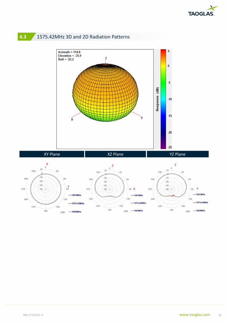
4.3 1575.42MHz 3D and 2D Radiation Patterns
XY Plane XZ Plane YZ Plane
Y
X
Y
Z
Z
X

13 SPE-17-8-072 -C www.taoglas.com
4.4 1602MHz 3D and 2D Radiation Patterns
XY Plane XZ Plane YZ Plane
Y
X
Y
Z
Z
X

14 SPE-17-8-072 -C www.taoglas.com
5.1 Block Diagram (Active Antenna)
Quadrature Coupler
5.2 Wibeband Return Loss
5. LNA Characteristics
4. Antenna Radiation Patterns3. Antenna
Characteristics
4. Antenna Radiation Patterns
4. Antenna Radiation Patterns3. Antenna
Characteristics
4. Antenna Radiation Patterns3. Antenna
Characteristics
4. Antenna Radiation Patterns
4. Antenna Radiation Patterns
4. Antenna Radiation Patterns
4. Antenna Radiation Patterns3. Antenna
Characteristics
4. Antenna Radiation Patterns3. Antenna
Characteristics

15 SPE-17-8-072 -C www.taoglas.com
5.3 Out of Band Rejection

16 SPE-17-8-072 -C www.taoglas.com
6. Mechanical Drawing (Units: mm)
6. Packaging5. Mechanical Drawing
6. Packaging
7. Application Note6. Packaging5. Mechanical
Drawing
6. Packaging5. Mechanical Drawing
6. Packaging
7. Application Note6. Packaging
7. Application Note
7. Application Note6. Packaging
7. Application Note6. Packaging5. Mechanical
Drawing
6. Packaging5. Mechanical Drawing

17 SPE-17-8-072 -C www.taoglas.com
7. Packaging
4. Antenna Radiation Patterns3. Antenna
Characteristics
4. Antenna Radiation Patterns
4. Antenna Radiation Patterns3. Antenna
Characteristics
4. Antenna Radiation Patterns3. Antenna
Characteristics
4. Antenna Radiation Patterns
4. Antenna Radiation Patterns
4. Antenna Radiation Patterns
4. Antenna Radiation Patterns3. Antenna
Characteristics
4. Antenna Radiation Patterns3. Antenna

18 SPE-17-8-072 -C www.taoglas.com
Introduction
Recent commercial developments in GNSS receivers have begun to make the dream of centimeter-level
outdoor positioning a reality for certain applications. These receivers use Real-Time Kinematic (RTK) or
Differential GNSS (DGNSS or DGPS) methods to reduce the impact on positioning accuracy of atmospheric
and similar effects.
To fully realize the potential of these systems, a high-performance single-band Quadrifilar (Quad) Helix
antenna has been developed by Taoglas. The AQHA.11 provides excellent phase and circular polarization
stability across frequency and space. These traits provide excellent multi-path rejection and phase center
stability.
To demonstrate this potential, a DGNSS system was constructed using standard commercial off-the-shelf
(COTS) receivers. The results are presented in this application note.
8. Application Note
6. Packaging5. Mechanical Drawing
6. Packaging
7. Application Note6. Packaging5. Mechanical
Drawing
6. Packaging5. Mechanical Drawing
6. Packaging
7. Application Note6. Packaging
7. Application Note
7. Application Note6. Packaging
7. Application Note6. Packaging5. Mechanical
Drawing
6. Packaging5. Mechanical Drawing

19 SPE-17-8-072 -C www.taoglas.com
Test Setup
The system was constructed around a pair of u-blox NEO-M8P boards from the C94-M8P evaluation kit
(Figure 1).
Figure 1 u-blox C94-M8P evaluation board (courtesy u-blox)
These boards were configured as a DGNSS system, with one acting as a base station and the other as a rover.
As is typical in this type of setup, the base station generates correction data and sends it to the rover. The
distance between the base station and rover (the baseline) was kept short (< 2m) to minimize baseline
effects. A Taoglas AQHA.11 was used as the base station antenna for all tests.
The base station was configured as an NTRIP server and provided RTCM v3.2 correction data. The rover used
an NTRIP client to receive the RTCM data. Like the hardware, COTS software (u-blox u-center) was used for
all data gathering and DGNSS operation. See the block diagram in Figure .

20 SPE-17-8-072 -C www.taoglas.com
U-blox M8P Receiver
U-blox M8P Receiver
Base Sation Rover
RTCM v3.2 over NTRIP
Figure 2 System configuration
To minimize the effects of satellite availability, the evaluation times were constricted to the 0000 – 0600 UTC
time frame. Since the GPS constellation is periodical with a 24h period, this meant the same GPS satellites
were available.
Some data points were removed during the evaluation to remove erroneous outliers. These points were:
• Data points with fewer than 5 satellites available
• Data points without DGPS in use
• Data points without a valid fix
• Data points without a relative position

21 SPE-17-8-072 -C www.taoglas.com
More than 7 satellites were available for all evaluation times. Dilution of Precision (DOP) metrics were not
restricted or constrained during this evaluation.
The rover receiver generated a relative position to the base station. This data was used for the analyses
below.
From the resulting 6 hours of data (around 20k data points), the following was calculated:
• Average 2D relative position using the North/East coordinate system
• Deviation of all relative positions from the average
• Standard deviation of North, East, and 2D deviations
Test Setup
AQHA.11 as Base Station Antenna
FXP611 as Rover
The Taoglas FXP611 Cloud is a high-efficiency flexible circuit GNSS antenna. It features wide bandwidth and
light weight, making it an excellent option for weight-sensitive applications.
Figure 3 Taoglas FXP611
The position deviation data points for the FXP611 are plotted in Figure .

22 SPE-17-8-072 -C www.taoglas.com
Figure 4 Relative position deviation map, FXP611 as rover
AQHA.11 as Rover
The AQHA.11 is a high-performance GNSS Quadrifilar Helix Antenna (QHA) supporting GPS L1, BeiDou B1,
and GLONASS G1. The AQHA.11 features wide bandwidth, wide gain and axial ratio beam width, and excellent
phase stability. The AQHA.11 provides an excellent choice for high-stability single-band GNSS positioning and
timing applications.
Figure 5 AQHA.11 Quad Helix Antenna

23 SPE-17-8-072 -C www.taoglas.com
The position deviation data points for the AQHA.11 are plotted in Figure .
Figure 6 Relative position deviation map, AQHA.11 as rover
Results Summary
Error! Reference source not found. provides a comparison summary of the results from Sections 0 and 0. A
primary focus is on the Standard Deviation (SD) of the deviation map. A larger SD depicts a wider spread of
positioning across the map showing a variable rate of accuracy. With the AQHA.11 however, we are clearly
seeing a tighter cluster of deviation data points indicating a much higher level of positioning accuracy.
Additionally, we are seeing similar metrics between the North and East indicating little or no pattern or phase
bias. What we have with the AQHA.11 is a more circular pattern, indicating that the fix is highly stable and
reliable by comparison to anything in the marketplace.
Metric FXP611 AQHA.11
SD, North 3.8 cm 0.4 cm
SD, East 4.2 cm 0.5 cm
SD, 2D 3.2 cm 0.5 cm
Max-Min, North 16 cm 3.2 cm
Max-Min, East 18 cm 3.3 cm
Table 1 Comparison Summary

24 SPE-17-8-072 -C www.taoglas.com
Conclusion
With modern GNSS receivers, it is possible to create a decimeter or centimeter level positioning system. A
lightweight, compact antenna such as the FXP611 can be used and still benefit from RTK or DGPS techniques
to provide decimeter-level positioning.
A high-performance antenna such as the AQHA.11, by contrast, can bring centimeter-level positioning and
timing solutions to a whole new level for a wide variety of applications such as Autonomous Driving,
Augmented Reality, Remote Monitoring and Connected Health to name a few that will deploy centimeter
level accuracy.

25 SPE-17-8-072 -C www.taoglas.com
Changelog for the datasheet
SPE-17-8-072 – AQHA.11.A.101111
Revision: C (Current Version)
Date: 2020-02-17
Changes: Updated Template
Changes Made by: Yu Kai Yeung
Previous Revisions
Revision: B
Date: 2020-01-16
Changes: Adding in the Base Station/Rover configuration data
Changes Made by: David Connolly
Revision: A (Original First Release)
Date: 2017-09-20
Notes: Initial Datasheet Release
Author: Jack Conroy

26 SPE-17-8-072 -C www.taoglas.com
www.taoglas.com
© Taoglas