
toro.pdf
6
A Transmit-Only/Receive-Only (TORO) RF System for High-Field MRI/MRS Applications Enzo A. Barberi, 1 Joseph S. Gati, 1 Brian K. Rutt, 1,2 and Ravi S. Menon 1,2 * The design and operation of a detunable shielded hybrid birdcage RF head coil optimized for human brain imaging at 170 MHz is presented. A high duty-cycle and rapid-switching decoupling scheme that allows uniform RF transmission with the head coil and reception with a surface coil within the volume of the head coil is also demonstrated. In addition, the circumscribing hybrid coil can be biased to operate as a conventional transmit/receive head- coil. Our RF design allows the use of higher sensitivity surface coils or phased-array coils at very high magnetic fields where body RF resonators are not currently available or whose use is precluded by specific-absorption ratio restrictions. The design also allows the use of receive-only coils within head gradient inserts, which normally do not allow transmission with an RF body resonator at any field strength. Magn Reson Med 43:284 –289, 2000. © 2000 Wiley-Liss, Inc. Surface coils offer considerable gains in signal-to-noise ratio (SNR) of a targeted volume in both spectroscopy and imaging experiments, but fall short in their ability to pro- duce a uniform RF field when used in a transmit mode. Clinical systems use transmit body RF coils actively de- coupled from receiver coils to circumvent the RF homo- geneity issue and exploit the SNR benefits of surface coil technology. The use of very-high-field scanners (.3 T) is also in large part driven by SNR issues, yet MRI/MRS techniques requiring the use of receive-only surface and phased-array coils have generally been unavailable at very high fields because of a lack of high-field transmit-only RF volume and body coils. Furthermore, many 3 T or higher systems, as well as many 1.5 T echo-planar imaging (EPI) retrofits, use a head gradient insert, making undistorted RF transmission with a body resonator impossible. Adiabatic pulses (1) in conjunction with transmit-receive surface coils offer a viable solution in some cases, but these are limited in applicability and pose certain specific-absorp- tion ratio (SAR) and pulse sequence restrictions. Here, we present the design and performance of a prototype high- field transmit-only/receive-only (TORO) RF system, com- prised of: a 28-cm diameter, 21-cm long transmit-only hybrid birdcage head coil; a single turn 8-cm diameter receive-only surface coil; and a custom fiberoptic gated transmit/receive (T/R) driver. This system permits the use of all pulse sequences with no modifications and no addi- tional SAR restrictions, and was developed for our 4 T Varian/Siemens Unity Inova whole-body MRI/MRS sys- tem (Palo Alto, CA, USA/Erlangen, Germany). Our TORO system permits the use of receive-only surface coils and phased-array coils, previously unavailable on very-high- field systems, and allows one to exploit their true poten- tial. The transmit-only coil described here is a modified form of the hybrid birdcage coil, which we have specifi- cally developed for head imaging and spectroscopy use at 3 T and 4 T (2) and have found to perform extremely well as a transmit-receive volume coil at these field strengths. One advantage of the hybrid design is its simplicity of construction in comparison to other more complex struc- tures (3,4). In this paper, we show specific coil modifica- tions that allow excellent decoupling of this hybrid bird- cage design from receive-only surface coils. THE HYBRID BIRDCAGE RESONATOR The hybrid birdcage is a single-tuned shielded birdcage resonator, which results from the combination of low pass and high pass lumped element capacitors, shown in Fig. 1 (2,5,6). This combination reduces continuous conductive element lengths to less than l/20. A 5-mm copper foil RF shield is also used because it reduces radiative losses and minimizes RF coil interaction with the system gradient coil shield. The 5-mm copper shield, with a calculated skin depth of 5 mm at 170 MHz, was found experimentally to reduce gradient eddy current artefacts encountered when using standard one ounce copper foil shield or copper mesh. RF shielding properties were identical regardless of whether the shield was 1 ounce copper, mesh, or 5-mm foil. Unlike similar structures that utilize lumped elements in both the rings and legs such as the double-tuned band- pass or band-stop birdcage (7) in which distributed and additional lumped element inductance’s are used, the hy- brid design is single tuned using only the distributed in- ductance of the birdcage. The mode 1 (homogeneous mode) frequency was determined using a field probe and the spectrum analyzer. Higher frequency (higher order) modes of the completed coil were .5 MHz upfield, about 1,000 times greater than the bandwidth of a typical RF excitation pulse. This in combination with the high-coil Q ensures that secondary modes are not excited. To achieve a single mode 1 resonance, the resonator is first tuned as a shielded high-pass birdcage to a mode 1 frequency approx- imately 30% lower than the final design frequency. This frequency has been empirically determined after con- structing various 8- and 16-element hybrid birdcages of differing lengths and diameters. For the range of diame- ters, lengths,and optimal shield spacings that are common for human head coils, this empirical recipe has been found to be accurate for the frequency range covering 40 –170 MHz. The high-pass capacitors are replaced with tempo- 1 Imaging Research Laboratories, John P. Robarts Research Institute, Lon- don, Ontario, Canada. 2 Department of Diagnostic Radiology and Nuclear Medicine, University of Western Ontario, London, Ontario, Canada. *Correspondence to: Dr. Ravi S. Menon, Laboratory for Functional Magnetic Resonance Research, The John P. Robarts Research Institute, P.O. Box 5015, 100 Perth Drive, London, Ontario, Canada N6A 5K8. E-mail: [email protected] Received 16 June 1999; revised 13 October 1999; accepted 14 October 1999. Magnetic Resonance in Medicine 43:284 –289 (2000) © 2000 Wiley-Liss, Inc. 284
-
Upload
samruddha-thakur -
Category
Documents
-
view
12 -
download
0
Transcript of toro.pdf

A Transmit-Only/Receive-Only (TORO) RF System forHigh-Field MRI/MRS Applications
Enzo A. Barberi,1 Joseph S. Gati,1 Brian K. Rutt,1,2 and Ravi S. Menon1,2*
The design and operation of a detunable shielded hybrid birdcageRF head coil optimized for human brain imaging at 170 MHz ispresented. A high duty-cycle and rapid-switching decouplingscheme that allows uniform RF transmission with the head coiland reception with a surface coil within the volume of the head coilis also demonstrated. In addition, the circumscribing hybrid coilcan be biased to operate as a conventional transmit/receive head-coil. Our RF design allows the use of higher sensitivity surfacecoils or phased-array coils at very high magnetic fields wherebody RF resonators are not currently available or whose use isprecluded by specific-absorption ratio restrictions. The designalso allows the use of receive-only coils within head gradientinserts, which normally do not allow transmission with an RF bodyresonator at any field strength. Magn Reson Med 43:284–289,2000. © 2000 Wiley-Liss, Inc.
Surface coils offer considerable gains in signal-to-noiseratio (SNR) of a targeted volume in both spectroscopy andimaging experiments, but fall short in their ability to pro-duce a uniform RF field when used in a transmit mode.Clinical systems use transmit body RF coils actively de-coupled from receiver coils to circumvent the RF homo-geneity issue and exploit the SNR benefits of surface coiltechnology. The use of very-high-field scanners (.3 T) isalso in large part driven by SNR issues, yet MRI/MRStechniques requiring the use of receive-only surface andphased-array coils have generally been unavailable at veryhigh fields because of a lack of high-field transmit-only RFvolume and body coils. Furthermore, many 3 T or highersystems, as well as many 1.5 T echo-planar imaging (EPI)retrofits, use a head gradient insert, making undistorted RFtransmission with a body resonator impossible. Adiabaticpulses (1) in conjunction with transmit-receive surfacecoils offer a viable solution in some cases, but these arelimited in applicability and pose certain specific-absorp-tion ratio (SAR) and pulse sequence restrictions. Here, wepresent the design and performance of a prototype high-field transmit-only/receive-only (TORO) RF system, com-prised of: a 28-cm diameter, 21-cm long transmit-onlyhybrid birdcage head coil; a single turn 8-cm diameterreceive-only surface coil; and a custom fiberoptic gatedtransmit/receive (T/R) driver. This system permits the useof all pulse sequences with no modifications and no addi-tional SAR restrictions, and was developed for our 4 TVarian/Siemens Unity Inova whole-body MRI/MRS sys-
tem (Palo Alto, CA, USA/Erlangen, Germany). Our TOROsystem permits the use of receive-only surface coils andphased-array coils, previously unavailable on very-high-field systems, and allows one to exploit their true poten-tial. The transmit-only coil described here is a modifiedform of the hybrid birdcage coil, which we have specifi-cally developed for head imaging and spectroscopy use at3 T and 4 T (2) and have found to perform extremely wellas a transmit-receive volume coil at these field strengths.One advantage of the hybrid design is its simplicity ofconstruction in comparison to other more complex struc-tures (3,4). In this paper, we show specific coil modifica-tions that allow excellent decoupling of this hybrid bird-cage design from receive-only surface coils.
THE HYBRID BIRDCAGE RESONATOR
The hybrid birdcage is a single-tuned shielded birdcageresonator, which results from the combination of low passand high pass lumped element capacitors, shown in Fig. 1(2,5,6). This combination reduces continuous conductiveelement lengths to less than l/20. A 5-mm copper foil RFshield is also used because it reduces radiative losses andminimizes RF coil interaction with the system gradientcoil shield. The 5-mm copper shield, with a calculated skindepth of 5 mm at 170 MHz, was found experimentally toreduce gradient eddy current artefacts encountered whenusing standard one ounce copper foil shield or coppermesh. RF shielding properties were identical regardless ofwhether the shield was 1 ounce copper, mesh, or 5-mmfoil.
Unlike similar structures that utilize lumped elementsin both the rings and legs such as the double-tuned band-pass or band-stop birdcage (7) in which distributed andadditional lumped element inductance’s are used, the hy-brid design is single tuned using only the distributed in-ductance of the birdcage. The mode 1 (homogeneousmode) frequency was determined using a field probe andthe spectrum analyzer. Higher frequency (higher order)modes of the completed coil were .5 MHz upfield, about1,000 times greater than the bandwidth of a typical RFexcitation pulse. This in combination with the high-coil Qensures that secondary modes are not excited. To achievea single mode 1 resonance, the resonator is first tuned as ashielded high-pass birdcage to a mode 1 frequency approx-imately 30% lower than the final design frequency. Thisfrequency has been empirically determined after con-structing various 8- and 16-element hybrid birdcages ofdiffering lengths and diameters. For the range of diame-ters, lengths,and optimal shield spacings that are commonfor human head coils, this empirical recipe has been foundto be accurate for the frequency range covering 40–170MHz. The high-pass capacitors are replaced with tempo-
1Imaging Research Laboratories, John P. Robarts Research Institute, Lon-don, Ontario, Canada.2Department of Diagnostic Radiology and Nuclear Medicine, University ofWestern Ontario, London, Ontario, Canada.*Correspondence to: Dr. Ravi S. Menon, Laboratory for Functional MagneticResonance Research, The John P. Robarts Research Institute, P.O. Box5015, 100 Perth Drive, London, Ontario, Canada N6A 5K8. E-mail:[email protected] 16 June 1999; revised 13 October 1999; accepted 14 October 1999.
Magnetic Resonance in Medicine 43:284–289 (2000)
© 2000 Wiley-Liss, Inc. 284

rary short circuit elements and the coil is then tuned(mode 1) to the same 30% lower frequency as a shieldedlow-pass birdcage. The short circuit elements are removedand the high-pass capacitors are reinserted. The mode 1resonance frequency then shifts up to the final designfrequency and fine tuning can be performed with trimmercapacitors or additional distributed capacitance in the legsor rings. This tuning technique, in addition to the lack oflumped element inductors mentioned above, distin-guishes the hybrid design from the band-pass and band-stop designs.
Typical capacitance values for a shielded, hybrid bird-cage coil, 279 mm in diameter, 210 mm in length, with a381-mm RF shield, and an operating frequency of 170.3MHz, are 36 pF at each end-ring gap, and 2.2 pF if one leggap is used. In the nomenclature of (6) we note that theratio of the leg capacitor to the end-ring capacitor is 0.061,consistent with a low-pass birdcage operating with a non-zero end-ring mode and slight mode compression. This isalso true of our original prototype hybrid coil (2), whichoperated at a ratio of 0.0377. We tend to use more than oneleg gap to distribute the components further, so in this case4.4 pF is used at each of 2 leg gaps. By comparison,high-pass and low-pass coils of identical dimensions re-quire 18 pF and 1 pF (if one leg gap is used) for the sameresonant frequency, respectively. This implies a higheruseful operating frequency limit for the hybrid designcompared to the high-pass, especially for the low-pass,which reaches it’s limit near 170 MHz for head-size coils(1 pF approaches the coil’s self-capacitance). We note thatthe low-pass coil is not well suited to very-high-field ap-plications. The continuous conductive end-ring of thelow-pass design with the above dimensions forms a quar-ter-wave length loop with an approximate radiation resis-tance of 10 ohms (8), a fairly effective antenna that pro-duces high near-electric field losses.
Coupling to the Hybrid Birdcage: End-Ring Direct-Coupled
We achieved coupling to the hybrid resonator with a bal-anced lumped-element quarter-wave variable impedance
transformer, and a fixed quarter-wave lattice balun (9) asshown in Fig. 2. A real input impedance is only obtainedwith the removal of the end-ring capacitors at each of thetwo orthogonal coil terminals (the shift in resonant fre-quency is easily compensated with variable capacitors typ-ically used to fine tune I and Q channel frequencies). Thefirst quarter-wave network serves to transform the resona-tor’s loaded input impedance to the customary 50 ohmimpedance of standard RF coaxial transmission lines. Ad-justments to accommodate various coil loads can be madewhen necessary through the two matched variable capac-itors shown. However, it has been found for this coildesign that with consistent placement of subjects in thecoil, no tuning adjustments are necessary between differ-ent subjects. The second network, a lumped-element quar-ter-wave balun in which all components have a 50 ohmimpedance serves to isolate the differential potentialspresent at the end-ring feed point from the coaxial trans-mission line shield, which is at or near ground potential.Impedances need only be matched to within a couple ofohms. This balun eliminates cable placement effects onquadrature channel isolation and coil impedance. Thebalun has no effect on the coupling of the electric fieldfrom the coil to the coaxial cables, therefore good RFcircuit layout techniques still apply. With this two stagearrangement, the matching and isolation functions are sep-arated and can be optimized and adjusted independently.Changes to the matching circuit do not greatly influence Iand Q channel isolation, which is typically 30 dB or betterfor a phantom or human subject.
T/R Driver
A T/R driver provides the gated DC bias necessary forelectronically turning coils on and off. We designed acustom T/R driver, comprised of a fiberoptic gated inputand separate TX and RX bias sections. The gating signalwas derived from the existing Varian/Siemens Unity Inovafiberoptic gating system. The TX stage applies a 290Vdcbias (TX coil on) and a -10Vdc bias (TX coil off) on the biasrails of the transmit-only coil. The RX stage applies a 210
FIG. 1. Pictorial representation of the shielded hybrid birdcage res-onator showing multiple lumped element capacitors distributed onthe resonator columns and end-rings. Note that no discrete induc-tors are used in the rings or legs.
FIG. 2. Two-stage coupling networks used to interface to the hybridbirdcage resonator. With this design, changes to the balancedmatching network do not affect I and Q channel isolation, and thedifferential voltage of the resonator feed points are well isolatedfrom the coaxial cable shields.
High-Frequency TORO RF System 285

Vdc bias (RX coil off) and a 5 Vdc bias (RX coil on) directlyto the receive-only coil input.
Transmit-Only Hybrid Birdcage Coil
The dimensions of the transmit-only coil were chosen tomatch those of our existing T/R receive hybrid birdcagehead coil for purposes of direct comparison. Active decou-pling of the transmit-only volume coil was achievedthrough the use of high voltage PIN diodes (UM4006B,Microsemi Corp.) distributed across one set of end-ringcapacitors, as shown in Fig. 3a and b. The T/R driverapplies a 290 V reverse bias (TX coil on) and a 210 Vforward bias (TX coil off) on the bias rails, which areconnected to the anode and cathode of the PIN diodes,respectively, through 1 mH RF choke inductors. The high-voltage reverse bias ensures that the PIN diodes are notdriven excessively into the forward conduction state anddestroyed by the RF power applied to the transmit-onlycoil. Choke inductors are also used on the bias rails tosuppress end-ring coupled current flow, which would oth-erwise lead to coil detuning when loaded with a subject.
Receive-Only Surface Coil
For the prototype TORO RF system, a simple single 8-cmloop coil was chosen for the receive-only function. Thedistributed series capacitors and single parallel capacitor
were used to match and tune the surface coil to 50 ohms,and the quarter wave lattice balun was used to isolate thereceive-only coil input terminals from system ground. Thetwo-stage active PIN diode decoupling of the single loopreceive-only coil is shown in Fig. 4. PIN diode 1 switchesin a parallel tuned inductor across the coil input capacitor,while PIN diode 2 short circuits the quarter-wave latticebalun, presenting an open circuit at the coil terminals.Passive decoupling through the use of a tuned inductorand a pair of crossed high speed switching diodes(1N6638U, Microsemi Corp.) was also included as a safetyprecaution. It should be stressed that our application de-mands excellent decoupling between the transmit-onlycoil and the receive-only coil, since the surface coil restson the 26.7-cm diameter inner bore of the transmit-onlycoil, with a coil-to-coil separation of just 3.5 cm. Thedecoupling diode configuration shown in our design wasrequired to meet this stringent decoupling requirement.
RESULTS
The T/R driver switching speed was assessed on the benchby monitoring the voltage on the bias lines of the transmit-only and receive-only coils. The limiting switching speedis found on the transmit-only coil, with 10% to 90% rise(coil on) and fall (coil off) times of 20 ms and 2 ms, respec-tively. The 2 ms turn off time was verified on our 4 T
FIG. 4. The receive surface coil decoupling scheme. The activedecoupling is comprised of a two-stage PIN diode switching design.A parallel inductor is switched across CP and a quarter wave latticebalun is effectively open circuited across the coil input at CP. Pas-sive decoupling with crossed high-speed switching diodes and adetuning inductor, switched in parallel with CS, is used as a pre-cautionary decoupling mechanism in the unlikely event of a PINdiode failure.
FIG. 3. Transmit volume coil decoupling. Schematic of end-ringdecoupling circuitry. a: The bias rails apply the appropriate bias,through the RF chokes (RFC), to the high voltage PIN diode (D)which switches an inductor (L) in parallel with the end-ring tuningcapacitor (C). Capacitor CDC is a DC block and an RF short. Withthis configuration, all PIN diodes are in DC parallel, permitting theapplication of the full forward and reverse DC bias voltage across alldiodes. b: View of the transmit coil with the RF shield removed,showing the DC bias rings and RF choke arrangement.
286 Barberi et al.

system by setting the receiver gate time to 2 ms and notingno measurable distortion in the resulting acquired spectra.
The change in coil sensitivity for the transmit-only coiland the receive-only coil, between on and off states, wasmeasured at 33 dB and 37 dB, respectively, using magneticfield probes and our spectrum analyser. Isolation of 33 dBbetween the transmit-only and receive-only coils was mea-sured on the bench by hooking up the transmit coil to thetransmit port of the analyser and the receive coil to theanalyzer’s receive port. Phased-array assemblies shouldhave the same characteristics. The excellent isolation be-tween coils is essential in maintaining transmit field uni-formity. The physical layout is shown in Fig. 5. The Sie-mens AS-25 gradient set on the scanner includes a slottedRF shield, which alters the resonant frequency and isola-tion in large unshielded coils, therefore, to evaluate thecoil in situ, the isolation was also assessed in the bore ofthe scanner. Spin echo images (TE 5 35 msec, TR 5 600msec) were acquired on a phantom with the transmit-onlycoil biased as a transmit-receive coil (Fig. 6). The phantomwas fabricated in house and consists of a 17-cm low di-electric oil filled sphere placed within a heavily dopedsaline solution filled loading cylinder. Phantom fluidswere chosen to minimize the dielectric effect of uniformwater phantoms (10,11). No changes in SNR and unifor-mity were observed with and without the decoupled re-ceive-only coil placed directly on the surface of the phan-tom (Fig. 6) demonstrating the efficiency of our decouplingscheme. Additionally, a comparison of the transmit-onlycoil, biased as a transmit-receive coil, with an identicallydimensioned conventional transmit-receive hybrid bird-cage revealed identical integral uniformity (15% 6 1%),SNR (440:1), and power requirements for identical 90°square pulses (1000 watts for a 200 ms square pulse) dem-onstrating that the addition of bias rings and chokes didnot compromise the head coil’s original sensitivity.
SNR profiles of the TORO system are compared withthose obtained from an 8 cm single turn transmit-receive
FIG. 5. A view of the TORO system coil placement that shows, witha coil-to-coil separation of 3.5 cm, the obvious need for excellentcoil isolation. Without excellent isolation, transmit field uniformitywould severely degraded. Figure 6 shows the effectiveness of theisolation.
FIG. 6. Signal intensity profiles of a 14.5-cm diameter oil phantom inthe (a) x, (b) y, and (c) z directions. Profiles are shown from imagesacquired with and without the surface coil in place (biased off) and theTORO coil biased as a transmit and receive coil. However, the profilesin these two conditions are indistinguishable, lying completely on top ofone another. The receive-only surface coil is located at the bottom ofthe phantom, i.e., right side of the y trace at approximately y 5170 mm.
High-Frequency TORO RF System 287
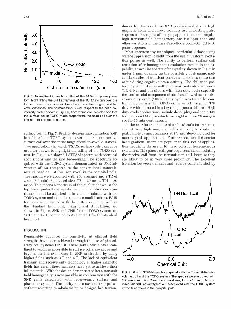
surface coil in Fig. 7. Profiles demonstrate consistent SNRbenefits of the TORO system over the transmit-receivesurface coil over the entire range of coil-to-voxel distances.Two applications in which TX/RX surface coils cannot beused are shown to highlight the utility of the TORO sys-tem. In Fig. 8, we show 1H STEAM spectra with identicalacquisitions and no line broadening. The spectrum ac-quired with the TORO system demonstrated an SNR ad-vantage of 4.0 compared to the conventional transmit-receive head coil at this 8-cc voxel in the occipital pole.The spectra were acquired with 256 averages and a TR of2 sec (8.5 min), 8-cc voxel size, TE 5 20 msec, TM 5 30msec. This means a spectrum of the quality shown in thetop trace, perfectly adequate for our quantification algo-rithms, could be acquired in less than a minute with theTORO system and no pulse sequence modifications. FAIRtime courses collected with the TORO system as well asthe standard head coil, using visual stimulation, areshown in Fig. 9. SNR and CNR for the TORO system are120:1 and 27:1, compared to 25:1 and 6:1 for the standardhead coil.
DISCUSSION
Remarkable advances in sensitivity at clinical fieldstrengths have been achieved through the use of phased-array coil systems (12,13). These gains, while often con-fined to volumes accessible to surface coils, are above andbeyond the linear increase in SNR achievable by usinghigher fields such as 3 T and 4 T. The lack of equivalenttransmit and receive only technology at higher magneticfields has meant these scanners have yet to achieve theirfull potential. With the design demonstrated here, transmitfield homogeneity is now possible in combination with theSNR gains associated with receive-only surface andphased-array coils. The ability to use 90° and 180° pulseswithout resorting to adiabatic pulse designs has tremen-
dous advantages as far as SAR is concerned at very highmagnetic fields and allows seamless use of existing pulsesequences. Examples of imaging applications that requirehigh transmit-field homogeneity are fast spin echo andother variations of the Carr-Purcell-Meiboom-Gill (CPMG)pulse sequence.
Most spectroscopy techniques, particularly those usingwater-suppression, benefit from the use of uniform excita-tion pulses as well. The ability to perform surface coilreception after homogeneous excitation results in the ca-pability to acquire spectra of the quality shown in Fig. 7 inunder 1 min, opening up the possibility of dynamic met-abolic studies of transient phenomena such as those thatoccur during cognitive brain activity. The ability to per-form dynamic studies with high sensitivity also requires aT/R driver and pin diodes with high duty cycle capabili-ties, and careful component choice has allowed us to pulseat any duty cycle (100%). Duty cycle was tested by con-tinuously biasing the TORO coil on or off using our T/Rdriver with no noted heating or equipment failures. Highduty cycle applications include decoupling and rapid EPIfor functional MRI, in which we might acquire 20 images/sec for 30 min continuously.
In the near future, the use of RF head coils for transmis-sion at very high magnetic fields is likely to continue;particularly as most scanners at 3 T and above are used forneurological applications. Furthermore, small-diameterhead gradient inserts are popular in this sort of applica-tion, requiring the use of RF head coils for homogeneousexcitation. This places stringent requirements on isolatingthe receive coil from the transmission coil, because theyare likely to be in very close proximity. The excellentisolation between transmit and receive coils afforded by
FIG. 8. Proton STEAM spectra acquired with the Transmit-Receivevolume coil and the TORO system. The spectra were acquired with256 averages, TR 5 2 sec, 8-cc voxel size, TE 5 20 msec, TM 5 30msec. An SNR advantage of 4.0 is achieved with the TORO systemat the 8-cc voxel in the occipital pole.
FIG. 7. Normalized intensity profiles of the 14.5-cm sphere phan-tom, highlighting the SNR advantage of the TORO system over thetransmit-receive surface coil throughout the entire range of coil-to-voxel distances. The normalization is with respect to the head coilintensity profile shown in Fig. 6b, from which one can also see thatthe surface coil in TORO mode outperforms the head coil over thefirst 51 mm into the phantom.
288 Barberi et al.

the decoupling scheme and baluns in our design maintainstransmit field homogeneity in spite of this close proximityof transmit and receive coils. The use of baluns also elim-inates cable placement effect on quadrature isolation andcoil impedance on volume and surface coils. This is im-portant for consistent and reproducible studies and is par-ticularly challenging at shorter wavelengths. The fastswitching T/R driver enables signal acquisition with thereceive-only coil 2 ms after the end of the transmit pulse,permitting the acquisition of ultra-short TE signals. Thishas potential benefit for the imaging of very short T2 spe-cies such as 23Na and complex flow fields.
CONCLUSION
The rapidly switching, high duty cycle TORO configura-tion described in this paper allows all pulse sequences,particularly those requiring homogeneous excitation, refo-cusing or inversion pulses to be performed with the highersensitivity of a surface coil. No pulse sequence modifica-tions are necessary and the full patient and RF safetysystem operation is preserved. The use of the hybrid coildesign will likely be advantageous for very large volumecoils, such as body coils at 4 T, in which capacitancevalues approach the coil self-capacitance for high-pass andlow-pass coils.
REFERENCES
1. Tannus A, Garwood M. Adiabatic pulses. NMR Biomed 1997;10:423–434.
2. Barberi EA, Rutt BK, Menon RS. An all stop birdcage resonator for veryhigh frequency applications. In: Proceedings of the 4th Annual Meetingof the ISMRM, New York, 1996. p 1417.
3. Vaughn JT, Hetherington HP, Out JO, Pan JW, Pohost GM. High fre-quency volume coils for clinical NMR imaging and spectroscopy. MagnReson Med 1994;32:206–218.
4. Wen H, Chesnick AS, Balaban RS. The design and test of a new volumecoil for high field imaging. Magn Reson Med 1994;2:492–498.
5. Edelstein WA, Schenck JF, Mueller OM, Hayes CE. Radio frequencyfield coil for NMR. US Patent 4,680,548.
6. Tropp J. The hybrid bird cage resonator. In: Proceedings of the 11thAnnual Meeting of the SMRM, Berlin, Germany, 1992. p 4009.
7. Rath AR. Design and performance of a Double tuned-tuned bird-cagecoil. J Magn Reson 1990;86:488–495.
8. Collin RE. Antennas and radiowave propagation. New York: McGraw-Hill; 1985.
9. Frankel S. Reactance networks for coupling between unbalanced andbalanced circuits. Proc IRE 1941;32:486–493.
10. Tofts PS, Barker GJ, Dean TL, Gallagher H, Gregory AP, Clarke RN. Alow dielectric constant customized phantom design to measure RF coilnonuniformity. Magn Reson Imag 1997;15:69–75.
11. Tofts PS. Standing waves in uniform water phantoms. J Magn ResonSeries B 1994;104:143–147.
12. Roemer PB, Edelstein WA, Hayes CE, Souza SP, Mueller OM. The NMRphased array. Magn Reson Med 1990;16:192–225.
13. Frederick B deB, Wald LL, Maas LC, Renshaw PF. A phased arrayechoplanar imaging system for fMRI. Magn Reson Imag 1999;17:121–129.
FIG. 9. FAIR time course using visual stimulation—TORO coil system and T/R head coil. SNR andCNR for the TORO system are 120:1 and 27:1,compared to 25:1 and 6:1 for the T/R head coil.
High-Frequency TORO RF System 289


