Toro Ecxtra Timer Manual
44
ECXTRA Features • Easily expandable to 10 Zones (Indoor model) or 12 Zones (Outdoor Model) with 2-zone Plug-in Modules • Snap-in Wire Connectors • Compatible with ECXTRA Scheduling Advisor TM • 3 Independent Watering Programs with: - Calendar, Interval and Odd/Even Days - Selective Day Exclusion - 1-minute to 4-hour Zone Run Time - 4 Start Times • Seasonal Run Time Adjust • Rain Delay • Compatible with Normally Closed or Normally Open Rain Sensors • Automatic 24V Circuit Protection • Program Memory Backup without Battery • Programmable Pump Start B C A MANUAL START ON NEXT OFF MANUAL START ON NEXT OFF Automatic Sprinkler System Control Timer User’s Guide INDOOR MODEL OUTDOOR MODEL
Transcript of Toro Ecxtra Timer Manual

ECXTRA Features
• Easily expandable to 10 Zones (Indoor model)or 12 Zones (Outdoor Model) with 2-zone Plug-in Modules
• Snap-in Wire Connectors• Compatible with ECXTRA Scheduling AdvisorTM
• 3 Independent Watering Programs with:- Calendar, Interval and Odd/Even Days- Selective Day Exclusion- 1-minute to 4-hour Zone Run Time- 4 Start Times
• Seasonal Run Time Adjust• Rain Delay• Compatible with Normally Closed or NormallyOpen Rain Sensors
• Automatic 24V Circuit Protection• Program Memory Backup without Battery• Programmable Pump Start
B CA
MANUALSTART
ON
NEXT
OFF
MANUALSTART
ON
NEXT
OFF
Automatic SprinklerSystem Control Timer
User’s Guide
INDOOR MODEL
OUTDOOR MODEL


Timer Components ........................................2-5
Timer Installation � Indoor Model Installation ................................6
� Connecting the Valves ....................................7� Connecting a Pump Start Relay......................8� Connecting the Transformer ...........................8
� Outdoor Model Installation .............................9� Preparing the Cabinet for Installation..............9� Installing the Cabinet.....................................10� Connecting the Valves ..................................11� Connecting a Pump Start Relay....................12� Connecting the Power Source ......................13
� Connecting a Rain Sensor...............................13
Getting Started � Sprinkler System Basics ..................................14� Watering Program Basics ................................15� Watering Program Details ..........................16-17� Planning Your Watering Schedule...................18� Filling Out the Watering Schedule Form.....18-19
� Watering Schedule Form ..............................20� About the Timer Memory .................................21
Programming the Timer� Setting the Current Time, Day and Date..........21� Setting the Watering Day Schedule............22-24
� Setting a Calendar Schedule ........................22� Setting an Interval Schedule .........................23� Setting an Odd or Even Schedule.................24� Using the Day Exclusion Feature .................25
Programming the Timer (continued)� Turning Off a Program ....................................26� Setting Program Start Times ...........................27� Setting Program Start Times ...........................27� Setting Zone Run Times .................................28� Pump Control ..................................................29
Timer Operations� Automatic Operation .....................................30� Manual Operation ..........................................31
� Starting Programs or Zones Manually...........31� Watering Control Features ............................32
� To Pause Watering .....................................32� To Resume Watering..................................32� To Cancel Watering ....................................32� To Skip Zones.............................................32� To Adjust the Zone Run TIme.....................33
� Using the Rain Delay Feature..........................33� Using the Season Adjust Feature ....................34� Turning Off the ECXTRA ................................35
Service and Specifications� Clearing the Program Memory.........................36� Automatic Circuit Protection ............................37� Adding a Zone Module.....................................37� Troubleshooting ...............................................38� Specifications...................................................39
Glossary of Terms.....................................39-41Warranty .............................................................42Electromagnetic Compatibility ................42
Table of Contents
1

Timer Components
Timer Components
2
SENSOR 24 VAC
MANUALSTART
ON
NEXT
OFF
B F

Timer Components
The following are brief descriptions of the timer components and display elements. Each of these itemswill be explained in further detail within the appropriateprogramming, operating and installation sections of this guide.
1 - LCD Display
A - “Start Time” symbol is displayed when setting theprogram start times.
B - Program start time identification numbers 1–4.
C - Main display of various time values and prompts.
D - Program A, B and C identifiers.
E - “Watering On” symbol is displayed when a watering zone is running. Symbol blinks whenwatering is paused.
F - “Watering Off” symbol is displayed when the Rain Delay feature is active.
G - “Percent” symbol is displayed when the SeasonAdjust feature is in use.
H - Watering zone identification numbers.
I - Day-of-the-week identifiers.
J - “Run Time” symbol is displayed when setting thewatering zone run times.
2 - Control Buttons
+/ON button – Increases the time display, scrolls forward through the program information and selectswatering days.
–/OFF button – Decreases the time display, scrollsbackward through the program information andremoves watering days.
NEXT button – Advances to the next portion of program information. Resumes watering if paused.Advances through stations manually when watering.
MANUAL START button – Selects and starts manualwatering operations.
3 - Control Dial – Selects all controller programmingand operation controls (except Manual Start).
Control Dial Positions
RUN – The normal dial position for all automaticand manual operations.
CURRENT TIME/DAY – Enables the clock timeand day to be set.
WATERING DAYS – Enables the watering dayschedules to be set and reviewed.
START TIMES – Enables the program start times tobe set and reviewed.
SET ZONE TIMES – Enables the watering zone runtime to be set and reviewed.
(continued)
3

Timer Components
3 - Control Dial Positions (continued)
SEASON ADJUST – Enables the run time of all stations in a program to be simultaneouslyincreased or decreased in 10% increments. SPECIAL FUNCTIONS – Provides optional controland timing features for pump operation.RAIN DELAY – Enables all watering operations tobe delayed from 1 to 7 days.OFF – Shuts off and prevents all automatic andmanual watering activity.
4 - Program Select Switch – Three-position slideswitch used to select watering program A, B or Cduring the programming procedures and manualoperation.
5 - Rain Sensor Control Switch – Controls the sensorinput circuit. Switch positions provided for sensor circuit Enable and Disable (bypass).
6 - Rain Sensor Configuration Switch – Selectseither Normally Open or Normally Closed sensoroperation for the type of sensor installed.
7 - Sensor Connection Terminals – Snap-in wire connector for (optional) Toro Rain Sensor.
8 - Valve Common Connection Terminal – Snap-inwire connector for the valve common wire.
9- Pump/Master Valve Connection Terminal – Snap-in wire connector for a pump start relay ormaster valve.
10 - Transformer Connection Terminals – Snap-inconnectors for the plug-in transformer wires.
11 - Plug-In 2- Zone Module – Each plug-in moduleprovides snap-in connectors for two zone controlvalve power wires. Up to six modules (12 zones)can in the installed in the outdoor timer model andfive modules (10 zones) in the indoor model.
12 - Time PodTM Port – Accepts the (optional) ECXTRATime Pod unit to transfer watering schedule datafrom the Toro Computer Aided Scheduling softwareprogram to the ECXTRA timer.
13 - Power Supply – A Plug-in transformer supplies 24 V a.c. power to the indoor controller models.
14 - Transformer – A built-in transformer supplies 24 V a.c. power to the outdoor controller models.
15 - Terminal Block – Connection terminals for 120 V a.c. power wires (Indoor model only).
4

5
B CA
MANUALSTART
ON
NEXT
OFF
SENSOR 24 VAC
MANUALSTART
ON
NEXT
OFF
Timer Components
Note: The ECXTRA indoor timer is not weather resis-tant and must be installed indoors or in a protectedarea.
1. Select a location for the timer within 4' of an electrical outlet to enable the transformer cord to easily reach. Make sure the outlet is not controlled by a light switch.
2. Remove the mounting bracket attached to the back of the timer housing by pulling the lower edge of thebracket away and downward from the timer housing.
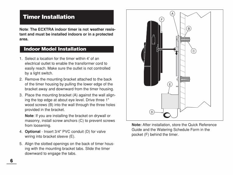
3. Place the mounting bracket (A) against the wall align-ing the top edge at about eye level. Drive three 1"wood screws (B) into the wall through the three holesprovided in the bracket.
Note: If you are installing the bracket on drywall ormasonry, install screw anchors (C) to prevent screwsfrom loosening.
4. Optional - Insert 3/4" PVC conduit (D) for valvewiring into bracket sleeve (E).
5. Align the slotted openings on the back of timer hous-ing with the mounting bracket tabs. Slide the timerdownward to engage the tabs.
Note: After installation, store the Quick ReferenceGuide and the Watering Schedule Form in the pocket (F) behind the timer.
Indoor Model Installation
Timer Installation
6
B
C
F
A
E
D

1. Route the valve control wires between the valves andthe timer.
Note: The snap-in wire connectors accept 14 to 18gauge wire. Using 18-gauge, multi-strand, direct-burialirrigation cable is recommended. Choose a cable thathas at least one more wire conductor than the numberof valves to be connected.
2. Attach the white color-coded wire to either one of thewires from each valve solenoid. This is called thevalve common wire.
3. Attach an individual color-coded wire to the remainingwire from each valve solenoid. Make a note of thewire color used for each valve and the watering zoneit controls. You will need to have this informationwhen connecting the valve wires to the timer.
CAUTION: Use Toro Waterproof Wire Connectors(Model # 53687) or grease caps on all exposed wiresplice connections to prevent corrosion, connectionfailure and possible short circuit.
4. Route the wire cable into the timer through the largeopening in the base of the housing or through PVCconduit (if it is installed). Strip insulation back 1/2"from all cable wires.
Note: The zone module has snap-in wire terminals.To attach wires, simply raise the lever, insert thestripped wire, and press the lever down to secure.
5. Referring to the Timer Components on page 5 and thediagram above, secure the valve common wire to theterminal labeled COM (8). Connect the individual zonevalve wires to the appropriate zone module terminals(11). Connect the master valve wire (if applicable) tothe terminal labeled PUMP/MV (9).
Note: Connecting a master valve or pump start relayis optional and may not be required in your sprinklersystem.
Connecting the Valves
7
SENSOR 24 VAC PUMP/MV COM
MANUALSTART
ON
NEXT
OFF
Valve Common WireZone ValvesMaster Valve
118 9

CAUTION: To prevent timer damage, ensure the24 V ac pump relay current draw does not exceed0.30 Amps. Do not connect the timer directly to thepump starter.
1. Route a wire pair from the pump relay into the timerhousing.
2. Connect one wire to the terminal labeled COM (8).Connect the remaining wire to the terminal labeledPUMP/MV (9) as shown below.
CAUTION: To prevent pump damage due to“dead-heading,” connect a jumper wire from anyunused zone terminal to a zone terminal with a valveconnected.
Note: Refer to “Pump Control” section on page 29 forimportant pump control information.
CAUTION: Do not plug the transformer into anelectrical outlet until all of the wiring procedureshave been completed.
1. Route the cord from the transformer (13) through thesmall opening provided in the base of the housing as shown below.
2. Connect one transformer cable wire to each terminallabeled 24 VAC (10). The wires can be connected toeither terminal.
Note: The display will begin flashing 12:00 AM. Press anybutton to stop the display from flashing.
Connecting the Plug-In TransformerConnecting a Pump Start Relay
8
SENSOR 24 VAC
ST
10
13SENSOR 24 VAC PUMP/MV COM
24 V a.c.Pump Relay Valve Common Wire
Jumper Wire
12
13

1. Remove the lower housing cover (A) by pulling outward on the handle.
2. Remove two phillips screws from the transformeraccess cover (B). Pull the cover outward from the bottom to remove.
3. Three lower mounting holes (C) are provided. Thecenter hole is open and the outer holes are plugged. Ifyou intend to use the outer holes for installation, care-fully drill through the plugs with a 3/16" drill bit.
Four wiring access holes are provided in the cabinet baseas follows:
(D) - 1/2" for power and equipment ground wires.
(E) - 1/2" (plugged) for optional Toro Rain Sensor wires.
(F) - 3/4" for sprinkler valve wires.
(G) -1/2" (plugged) for optional Toro remote control cable.
4. If planning to install the optional Toro components,remove the plugs as necessary.
Outdoor Model Installation
Preparing the Cabinet for Installation
9
MANUALSTART
ON
NEXT
OFF
MANUALSTART
ON
NEXT
OFF
PROGRAMS
B CA
RRRR
B CA
MANUALSTART
ON
NEXT
OFF
A
B
C
FED G

1. For safe, reliable operation, select an installation sitewhich will provide the following conditions:• Protection from irrigation spray, exposure to direct
sun during the hottest hours, wind and snow.• Access to a grounded power source which is not
controlled by a light switch or utilized by a high current load appliance, such as a refrigerator or airconditioner.
• Access to the sprinkler control valve wiring andoptional accessory wiring.
2. Drive a wood screw (provided) into the wall at eyelevel (A). Leave the screw extended approximately1/4" from the wall.
Note: If you are installing the timer on drywall ormasonry, install screw anchors to prevent screwsfrom loosening. Use the dimension shown to predrillholes for screw anchors.
3. Hang the cabinet on the screw using the keyhole slot (B) on the back panel. Make sure the cabinetslides down securely on the screw.
4. Install the lower mounting screw(s) and tightensecurely.
Note: Conduit and adapters are not provided. Installconduit as required by local electrical codes.
5. Install 1/2" conduit (C) for power/equipment groundwires and 3/4" conduit (D) for valve wires.
Note: After installation, store the User’s Guide andQuick Reference Guide on the hook located on theinside of the door.
Installing the Cabinet
10
MANUALSTART
ON
NEXT
OFF
6"
BA
DC

11
1. Route the valve wires or wire cable from the valves,into the timer cabinet.
Note: The snap-in wire connectors accept 14 to 18gauge wire. Using 18-gauge, multi-strand, direct-burialirrigation cable is recommended. Choose a cable thathas at least one more wire conductor than the numberof valves to be connected.
2. Attach the white color-coded wire to either one of thewires from each valve solenoid. This is called thevalve common wire.
3. Attach an individual color-coded wire to the remainingwire from each valve solenoid. Make a note of thewire color used for each valve and the watering zoneit controls. You will need to have this informationwhen connecting the valve wires to the timer.
CAUTION: Use Toro Waterproof Wire Connectors(Model # 53687) or grease caps on all exposed wiresplice connections to prevent corrosion, connectionfailure and possible short circuit.
4. Route the wire cable into the timer through the largeopening in the base of the housing or through PVCconduit (if it is installed). Strip insulation back 1/2"from all cable wires.
Note: The zone module has snap-in wire terminals.To attach wires, simply raise the lever, insert thestripped wire, and press the lever down to secure.
5. Referring to the Timer Components on page 5 and thediagram above, secure the valve common wire to theterminal labeled COM (8). Connect the individual zonevalve wires to the appropriate zone module terminals(11). Connect the master valve wire (if applicable) tothe terminal labeled PUMP/MV (9).
Note: Connecting a master valve or pump start relayis optional and may not be required in your sprinklersystem.
Connecting the Valves
Valve CommonWire
ZoneValves
MasterValve
11
8
9

CAUTION: To prevent timer damage, ensure therelay current draw does not exceed 0.30 Amps. Donot connect the timer directly to the pump starter.
1. For pump relay wires, install a 1/2" conduit adapterand conduit.
2. Connect a wire pair to the pump relay terminals androute the cable through the conduit and into the timerhousing.
3. Connect one wire to the terminal labeled COM (12).Connect the remaining wire to the terminal labeledPUMP/MV (13) as shown below.
CAUTION: To prevent pump damage due to“dead-heading,” connect a jumper wire from anyunused zone terminal to a zone terminal with a valveconnected.
Note: Refer to “Pump Control” section on page 29 forimportant pump circuit control information.
1. Route the power and equipment ground wires from thepower source, through the conduit and into the timertransformer compartment.
Note: The timer terminal block accepts wire size up to14 gauge.
2. Remove 3/8" insulation from the wire ends.
3. Using a small flat blade screwdriver, secure the wiresas shown to the terminal block as follows:Line or Line 1 (L1) to L, Neutral or Line 2 (L2) to Nand Equipment Ground to .
4. Install and secure the transformer compartmentcover.
5. Apply power to the timer.
Note: The display will begin flashing 12:00 AM. Press anybutton to stop the display from flashing.
Connecting the Power SourceConnecting a Pump Start Relay
12
24 V a.c.Pump Relay
Valve Common Wire
Jumper Wire
WARNING:AC power wiring must be installed and connectedby qualified personnel only. All electrical compo-nents and installation procedures must complywith all applicable local and national electricalcodes. Some codes may require a means of discon-nection from the AC power source installed in thefixed wiring and having a contact separation of atleast 0.120" in the line and neutral poles.
Make sure the power source is OFF prior to con-necting the timer.
12
13

(Optional)
A rain sensor is a remote device which can be connect-ed directly to your ECXTRA to automatically interruptwatering during rain.
A sensor control switch is provided to enable the sensoroperation to be turned On and Off as needed.
When the rain sensor absorbs rain water it automaticallysignals the ECXTRA to suspend all watering operations.The “No Watering” symbol will appear in the upper rightcorner of the display until the sensor drys out and auto-matically resets. The symbol will disappear and timeroperation will resume as programmed.
1. Route the two sensor wires from the device into thetimer housing through the access hole provided.
2. Remove the plastic piece from the Sensor terminal connectors. Connect the two sensor wires in any order.
3. Set the Sensor Configuration Switch (5) to NC(Normally Closed) or NO (Normally Open) operation as required by the type of sensor connected.
Note: Refer to the instructions provided with the rainsensor to determine NC or NC switch type and foradditional installation and operating information.
4. Set the Sensor Control Switch (6) as required: ENB(enable) allows the rain sensor to interrupt watering;DIS (disable) bypasses the rain sensor input.
IMPORTANT: Do not use the ENB switch positionwith the NC switch position unless a Normally Closedrain sensor is connected. Watering operation will besuspended if this condition occurs.
Connecting a Rain Sensor
Connecting the Power Source (cont.)
13
MANUALSTART
ON
NEX
OFF
6
5
Rain Sensor
Remove
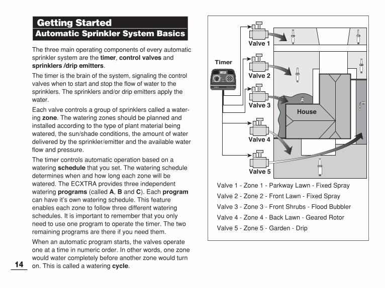
The three main operating components of every automaticsprinkler system are the timer, control valves andsprinklers /drip emitters.
The timer is the brain of the system, signaling the controlvalves when to start and stop the flow of water to thesprinklers. The sprinklers and/or drip emitters apply thewater.
Each valve controls a group of sprinklers called a water-ing zone. The watering zones should be planned andinstalled according to the type of plant material beingwatered, the sun/shade conditions, the amount of waterdelivered by the sprinkler/emitter and the available waterflow and pressure.
The timer controls automatic operation based on awatering schedule that you set. The watering scheduledetermines when and how long each zone will bewatered. The ECXTRA provides three independentwatering programs (called A, B and C). Each programcan have it’s own watering schedule. This featureenables each zone to follow three different wateringschedules. It is important to remember that you onlyneed to use one program to operate the timer. The tworemaining programs are there if you need them.
When an automatic program starts, the valves operateone at a time in numeric order. In other words, one zonewould water completely before another zone would turnon. This is called a watering cycle.
Getting StartedAutomatic Sprinkler System Basics
14
MANUALSTART
ON
NEXT
OFF
Valve 1 - Zone 1 - Parkway Lawn - Fixed Spray
Valve 2 - Zone 2 - Front Lawn - Fixed Spray
Valve 3 - Zone 3 - Front Shrubs - Flood Bubbler
Valve 4 - Zone 4 - Back Lawn - Geared Rotor
Valve 5 - Zone 5 - Garden - Drip
Valve 1
Timer
Valve 2
HouseValve 3
Valve 4
Valve 5
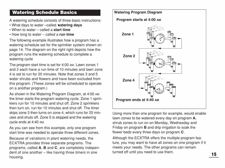
A watering schedule consists of three basic instructions: • What days to water –called watering days• When to water – called a start time• How long to water – called a run time
The following example illustrates how a program has awatering schedule set for the sprinkler system shown onpage 14. The diagram on the right right depicts how theprogram runs the watering schedule to complete awatering cycle
The program start time is set for 4:00 AM. Lawn zones 1and 2 each have a run time of 10 minutes and lawn zone4 is set to run for 20 minutes. Note that zones 3 and 5water shrubs and flowers and have been excluded fromthis program. (These zones will be scheduled to operateon a another program.)
As shown in the Watering Program Diagram, at 4:00 AM
the timer starts the program watering cycle. Zone 1 sprin-klers run for 10 minutes and shut off. Zone 2 sprinklersthen turn on, run for 10 minutes and shut off. The timerskips zone 3 then turns on zone 4, which runs for 20 min-utes and shuts off. Zone 5 is skipped and the wateringcycle ends at 4:40 AM.
As you can see from this example, only one programstart time was needed to operate three different zones.
Because of variations in plant watering needs, theECXTRA provides three separate programs. The programs, called A, B and C, are completely indepen-dent of one another – like having three timers in onehousing.
Using more than one program for example, would enablelawn zones to be watered every day on program A,shrub zones to run on on Monday, Wednesday and Friday on program B and drip irrigation to soak theflower beds every three days on program C.
Although the ECXTRA offers the multiple program fea-ture, you may want to have all zones on one program if itmeets your needs. The other programs can remainturned off until you need to use them.
Watering Schedule Basics
15
3
12
9
6
3
12
9
6
3
12
9
6
Zone 1
Program starts at 4:00 AM
Program ends at 4:40 AM
Zone 2
Zone 4
Watering Program Diagram
16
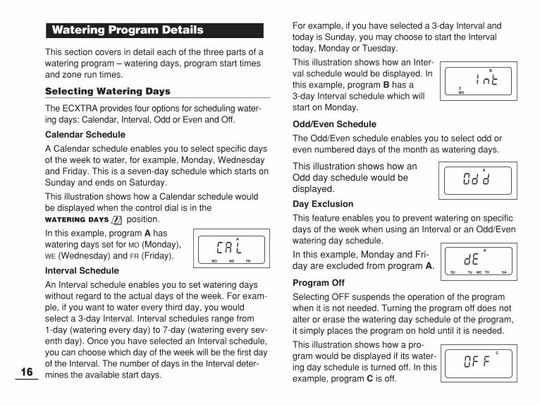
This section covers in detail each of the three parts of awatering program – watering days, program start timesand zone run times.
Selecting Watering Days
The ECXTRA provides four options for scheduling water-ing days: Calendar, Interval, Odd or Even and Off.
Calendar Schedule
A Calendar schedule enables you to select specific daysof the week to water, for example, Monday, Wednesdayand Friday. This is a seven-day schedule which starts onSunday and ends on Saturday.
This illustration shows how a Calendar schedule wouldbe displayed when the control dial is in theWATERING DAYS position.
In this example, program A haswatering days set for MO (Monday),WE (Wednesday) and FR (Friday).
Interval Schedule
An Interval schedule enables you to set watering dayswithout regard to the actual days of the week. For exam-ple, if you want to water every third day, you wouldselect a 3-day Interval. Interval schedules range from 1-day (watering every day) to 7-day (watering every sev-enth day). Once you have selected an Interval schedule,you can choose which day of the week will be the first dayof the Interval. The number of days in the Interval deter-mines the available start days.
For example, if you have selected a 3-day Interval andtoday is Sunday, you may choose to start the Intervaltoday, Monday or Tuesday.
This illustration shows how an Inter-val schedule would be displayed. Inthis example, program B has a 3-day Interval schedule which willstart on Monday.
Odd/Even Schedule
The Odd/Even schedule enables you to select odd oreven numbered days of the month as watering days.
This illustration shows how anOdd day schedule would be displayed.
Day Exclusion
This feature enables you to prevent watering on specificdays of the week when using an Interval or an Odd/Evenwatering day schedule.
In this example, Monday and Fri-day are excluded from program A.
Program Off
Selecting OFF suspends the operation of the programwhen it is not needed. Turning the program off does notalter or erase the watering day schedule of the program,it simply places the program on hold until it is needed.
This illustration shows how a pro-gram would be displayed if its water-ing day schedule is turned off. In thisexample, program C is off.
Watering Program Details
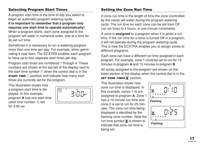
Selecting Program Start TimesA program start time is the time of day you select tobegin an automatic program watering cycle. It is important to remember that a program onlyrequires one start time to operate automatically!When a program starts, each zone assigned to the program will water in numerical order, one at a time forits set run time.
Sometimes it is necessary to run a watering programmore than one time per day. For example, when germi-nating a new lawn. The ECXTRA enables each programto have up to four separate start times per day.
Program start times are numbered 1 through 4. Thesenumbers are shown at the top left of the display next tothe start time symbol when the control dial is in theSTART TIME position and indicate how many starttimes are currently set for the program.
This illustration shows how a program start time is dis-played. In this example, program A has one start time(start time number 1) set for 3:00 AM.
Setting the Zone Run Time
A zone run time is the length of time the zone (controlledby the valve) will water during the program wateringcycle. The run time for each zone can be set from Off(no run time) to 4 hours, in one-minute increments.
A zone is assigned to a program when it is given a runtime. If the run time for a zone is turned Off in a program,it will not operate during the program watering cycle.This is how the ECXTRA enables you to assign zones todifferent programs.
Each zone can have a different run time assigned in eachprogram. For example, zone 1 could be set to run for 15minutes in program A and 10 minutes in program B.
All zones assigned to the program are shown on thelower portion of the display when the control dial is in theSET ZONE TIMES position.
This illustration shows how zone run time is displayed. Inthis example, zones 1–6 areassigned to program A. Zone 1has a 10-minute run time andzone 2 is set to run for 25 min-utes. The zone run time beingdisplayed is identified by theflashing zone number. Note therun time symbol is shown toindicate that zone run time isbeing set.
17
Flashing
Flashing

18
Note: You can use your PC and Toro’s exclusive CAS(Computer Aided Scheduling) interactive software to guideyou through the complete watering schedule process.When ready, simply transfer the schedule information tothe ECXTRA with the Time Pod and it’s ready to run.
It is always helpful to plan your watering schedule onpaper before beginning the programming steps. You will have a record of your watering schedule and zonelocations which can be kept with your ECXTRA after it isinstalled. If you have an indoor model timer, a wateringschedule form is provided on page 20 for you to fill outthen remove to keep with the timer. This form is duplicatedon a decal located on the inside cover of the outdoormodel timer.
Guidelines for Watering There are several factors to be considered when decid-ing when and how long to water. For example, the soiltype (i.e., clay, loam, etc.), the part of the landscapebeing watered, climate conditions and the type of sprin-klers being used. Because of these variables, we cannotprovide an exact schedule to follow, but here are somegeneral watering guidelines to help you get started.
• Water early in the morning, one to two hours beforesunrise. You will have the best water pressure at thistime and the water can soak into the plant root zonewhile evaporation is minimal. Watering during mid-dayor in the evening may cause plant damage or mildew.
• Watch for signs of under- or over-watering and makeprogram adjustments immediately.
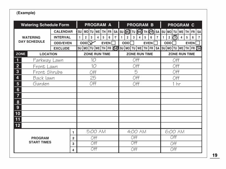
Filling Out the Watering Schedule FormWhen filling out this form, use a pencil so changes can beeasily made. After installing the indoor model timer,remove the form and store it in the pocket formedbetween the mounting bracket and the back of the timerhousing. Refer to the example form shown on the oppo-site page and fill out your form in a similar manner withthe following information:
• Location - Identify the location of each watering zoneand the type of plant being watered. Note: Enter the following information for each pro-gram. If the program is not needed, leave its informa-tion column blank.
• Watering Day Schedule - For a Calendar schedule,circle day(s) of the week watering is desired. For anInterval schedule circle the desired Interval number.For Odd or Even days, simply mark the appropriatebox. If you need to restricted watering on certain days,circle the Exclude day(s).
• Zone Run Time - Indicate the amount of run time (1 minute to 4 hours) for each zone. Write “Off” for anyzone which you do not want to operate in the program.
• Program Start Times - Indicate the time of day tostart the program. Each program can have 1 to 4 starttimes per watering day.Note: A start time that occurs while a wateringcycle is in progress will be delayed until the cur-rent watering cycle is finished. Therefore, whenusing multiple start times within a program or whenusing multiple programs, schedule the start times toallow each watering cycle to run completely before thenext cycle starts.
Planning Your Watering Schedule
19
SU MO TU WE TH FR SA SU MO TU WE TH FR SA SU MO TU WE TH FR SA
MOSU TU WE TH FR SA SU MO TU WE TH FR SA SU MO TU WE TH FR SA
1 2 3 4 5 6 7 1 2 3 4 5 6 7 1 2 3 4 5 6 7
CALENDAR
LOCATION ZONE RUN TIME ZONE RUN TIME ZONE RUN TIME
WATERING DAY SCHEDULE
INTERVAL
EXCLUDE
ODDODD/EVEN EVEN
PROGRAMSTART TIMES
1
2
3
4
PROGRAM AWatering Schedule Form PROGRAM B PROGRAM C
ODD EVEN ODD EVEN
123456789
101112
ZONE
(Example)

20
SU MO TU WE TH FR SA SU MO TU WE TH FR SA SU MO TU WE TH FR SA
MOSU TU WE TH FR SA SU MO TU WE TH FR SA SU MO TU WE TH FR SA
1 2 3 4 5 6 7 1 2 3 4 5 6 7 1 2 3 4 5 6 7
CALENDAR
LOCATION ZONE RUN TIME ZONE RUN TIME ZONE RUN TIME
WATERING DAY SCHEDULE
INTERVAL
EXCLUDE
ODDODD/EVEN EVEN
PROGRAMSTART TIMES
1
2
3
4
PROGRAM AWatering Schedule Form PROGRAM B PROGRAM C
ODD EVEN ODD EVEN
123456789
101112
ZONE

About the Watering Program MemoryOnce programmed, the ECXTRA memory will beretained for several years without power. Only the cur-rent time and date information will be lost and will needto be reset if power is disconnected from the timer formore than 24 hours. The ECXTRA has a permanent (default) watering sched-ule that can operate your sprinkler system automaticallywhen power is first applied.The default watering schedule operates as follows:
• Program A has a Calendar watering schedule set towater every day.
• One program start time is set for 5:00 AM (5:00).
• A run time of 10 minutes is set for each zone and thepump start/master circuit will be turned on.
• Programs B and C are turned Off (no watering programsettings).
• Master Valve/Pump Start circuit On/Off is On.
• Season Adjust is 100%
• Pump Delay time is 0 (zero).
If you do not wish to program the timer, you can usethe default watering schedule as is. With the current time and date set, your ECXTRA will beready to operate automatically.
Note: The watering program memory can be reset to thedefault program at any time. See “Clearing the ProgramMemory” on page 36 for detailed information
Turn the control dial to the CURRENT TIME/DAY
position (the hour digits will begin flashing).
Note: The time of day will be displayed in hours andminutes (12-hour format). To select a 24-hour format,press the next button repeatedly to display 12 H. Pressthe +/ON button to display 24 H. Press the next buttononce (the hour digits will begin flashing).
To adjust the display, press the +/ON button to scrollthe digits forward or the –/OFF button to scroll thedigits backward.
Note: The display will begin to change rapidly if either button is held down for more than two seconds.
Press the NEXT button to select the next portion ofthe display.
4. Repeat steps and to set the following currentinformation: minutes, year, month and day.
When the current time and day are displayed, returnthe control dial to the RUN position.
Setting the Current Time and DateProgramming the Timer
21
Day
Month

22
Note: For each program, you can select Calendar, Inter-val Odd, Even or Off. To set a Calendar schedule, con-tinue here. To set an Interval schedule see page 23. Toset an Odd or Even schedule, see page 24. To turn Off aprogram, see page 26.
Setting a Calendar Schedule
Turn the control dial to the WATERING DAYS
position.
Check the PROGRAMS switch setting. If necessary,reposition the switch to select the desired program.
The current watering schedule will be displayed. IfCAL (Calendar) is not displayed, press the +/ON or–/OFF button as needed to select CAL.
Press the NEXT button. The watering days currentlyset for this program will be displayed. SU (Sunday)will begin flashing.
To select Sunday as a watering day, press the +/ON
button. To remove Sunday from the schedule, pressthe –/OFF button; MO (Monday) will now begin flash-ing. Continue to select or remove each day of theweek until only the desired watering days are shown
6. To set a Calendar schedule for another program,repeat all of the steps beginning at step .
When you have completed setting the Calendarschedule for each program (as needed) return thecontrol dial to the RUN position.
Note: Each program can have its own Calendar, Inter-val or Odd/Even schedule, but only one schedule canbe active at a time for that program. The watering dayschedule or OFF shown in the display when the controldial is in the WATERING DAYS position, will be thecurrent schedule for that program.
Setting the Watering Day Schedule
7
4
5
23
3 5
354
1

23
Setting an Interval Schedule
Turn the control dial to the WATERING DAYS
position.
Check the PROGRAMS switch setting. If necessary,reposition the switch to select the desired program.
The current watering schedule will be displayed. IfInt (Interval) is not displayed, press the +/ON or–/OFF button as needed to select Int.
Press the NEXT button. The current Interval number(1–7) will begin flashing.
To change the Interval number, press the +/ON or–/OFF button until the desired number is flashing.
Press the NEXT button. The Interval start day willbegin flashing.
To change the Interval start day, press the +/ON
button or the –/OFF button until the desired day isflashing.
8. To set an Interval schedule for another program,repeat all of the steps beginning at step .
When you have completed setting the Intervalschedule for each program (as needed), return thecontrol dial to the RUN position.
Note: The Day Exclusion feature enables you toselect any day(s) of the week to be excluded andremain off when using an Interval or Odd/Evenwatering schedule. See page 25 for detailed information.
7
6
23
9
4
7557 4
3 5
36
1

Setting an Odd or Even Schedule
Turn the control dial to the WATERING DAYS
position.
Check the PROGRAMS switch setting. If necessary,reposition the switch to select the desired program.
The current watering schedule will be displayed. IfOdd or Even is not displayed, press the +/ON or–/OFF button as needed to select Odd or Even.
Note: When Odd is selected, the 31st day of themonth and the 29th day of a leap year will not beactive watering days.
4. To set an Odd or Even schedule for another program, repeat steps and as needed.
When you have completed setting the Odd or Evenschedule for each program as needed, return thecontrol dial to the RUN position.
Note: The Day Exclusion feature enables you toselect any day(s) of the week to be excluded andremain off when using an Interval or Odd/Evenwatering schedule. See page 25 for detailed information.
24
23
5
3
31

Using the Day Exclusion Feature
A Calendar watering day schedule is used to select spe-cific days of the week to water. However, if an Interval orOdd/Even watering schedule is preferred (or requireddue to watering restrictions in your area), specific days ofthe week can be removed from the watering schedule byusing the Day Exclusion feature.
Note: The Day Exclusion feature applies only to the anInterval or Odd/Even watering schedule and will not bedisplayed if the selected program is set to use a Calen-dar watering schedule.
Turn the control dial to the WATERING DAYS
position.
Check the PROGRAMS switch setting. If necessary,reposition the switch to select the desired program.
The current watering schedule (Interval orOdd/Even) will be displayed. Press the NEXT buttonas needed to display d E (Day Exclusion). The daysof the week will be displayed and SU (Sunday) willbegin flashing.
To exclude Sunday from the watering schedule,press the –/OFF button. To keep Sunday and skip tothe next day, press the +/ON button; MO (Monday)will now begin flashing. Continue to exclude or skipeach day of the week as needed.
Example: Tuesday and Friday have been excludedfrom program A.
When finished, return the control dial to the RUN
position.
25

Turning Off a Program
Note: Turning off a program does not alter or erase apreset watering day schedule. Selecting Off simplyplaces the program on hold until one of the watering dayschedules is selected.
Turn the control dial to the WATERING DAYS
position.
Check the PROGRAMs switch setting. If necessary,reposition the switch to select the desired program.
Press the +/ON or –/OFF button until OFF is flashing.
4. To turn another program Off, repeat steps andas needed.
Return the control dial to the RUN position.
26
23
5
3
31

Turn the control dial to the PROGRAM START TIME
position.
Check the PROGRAMS switch setting. If necessary,reposition the switch to select the desired program.
Program start time number 1 will begin flashing. Thecurrent program start time or OFF will be displayedfor start time number 1. To select a different programstart time number, press the +/ON or the –/OFF buttonuntil the desired number is flashing.
Note: The numbers (1–4) shown at the top of the displaydesignate program start times and should not be con-fused with zone numbers. The zone numbers will beshown at the bottom of the display when setting zone runtime.
Press the NEXT button. The hour digit(s) or OFF willbegin flashing.
Note: To remove the start time, select OFF bypressing the +/ON and –/OFF buttons at the sametime, and continue at step .
To set the hour (and AM/PM), press the +/ON or the–/OFF button until the desired hour is flashing.
Press the NEXT button. The minute digits will beginflashing.
To set the minutes, press the +/ON or –/OFF buttonuntil the desired minute is flashing.
Press the NEXT button. The next program start timenumber will begin flashing.
To select another start time number, press the +/ON
or the –/OFF button until the desired start time num-ber is flashing.
10. To set, change or remove a program start time forthe start time number selected, repeat all of thesteps starting at step .
11. To set program start times for another program,repeat all of the steps starting at step .
Return the control dial to the RUN position.
Setting Program Start Times
27
12
3 5 7 9
14 6 8
4 5 6 7
9 23
3 75 9

PGM A
1 2 3 4 5 6
3 5
3 5
9�
�4
3
5
21
42
5
Turn the control dial to the SET ZONE TIMES
position.
Check the PROGRAMS switch setting. If necessary,reposition the switch to select the desired program.
Zone number 1 will be flashing and its current runtime or OFF will be shown. To select a different zonenumber, press the +/ON or –/OFF button until thedesired zone number is flashing.
Press the NEXT button. The run time (or OFF) willbegin flashing.
To set the run time, press the +/ON or –/OFF buttonuntil the desired run time is shown.
Note: To remove the run time, select OFF by press-ing the +/ON and –/OFF buttons at the same time.
Press the NEXT button. The next zone number willbegin flashing.
7. Repeat steps and as needed to set, change,or remove the run time for the remaining zones.
8. To set the zone run time for another program, repeatall of the steps starting at step .
Return the control dial to the RUN position.
Note: Basic programming is now complete. If the ECXTRA is controlling a water supply pump, continue at “Pump Control” on page 29 for importantoperating information.
Setting Zone Run Times
28
3
9
3 5
14 5
3 5
542

The Special Functions dial position provides optional control features specifically for pump system operation.Pump/Master Valve control circuit operation is active(On) with two seconds of delay time (turns on two sec-onds before the first zone begins watering) but can beturned Off for each watering program as needed.The pump delay time can be adjusted from 1 to 60 seconds.
Turn the control dial to the SPECIAL FUNCTIONS
position.
Check the PROGRAMS switch setting. If necessary,reposition the switch to select the desired program.
3. The display will show P On (Pump On) and willbegin flashing.
To turn the pump circuit Off for this program, pressthe –/OFF button; P OFF will be displayed.
Press the NEXT button to display the pump delaytime. Pd 02 will be displayed. (A two-second pumpdelay is set by default for each program).
Press the +/ON or –/OFF button until the desired timeis shown (2 to 60 seconds).
Pump Control
29
1
6
35
2
4
6
5

The ECXTRA timer has three modes of operation: Auto-matic, Manual and Off. In the Automatic mode the timertracks the time and day and operates the automaticwatering schedules. The Manual mode enables thezones and watering programs to be started and con-trolled manually at any time. The Off mode shuts off allwatering activity and prevents any zones from operatingautomatically or manually.
The Rain Delay and Season Adjust control features areprovided to enable quick, temporary changes in operationto help compensate for variables in weather and season.
Each of the operating modes and control features areexplained in this section of the guide and can be foundon the following pages:
• Automatic Operation, page 30• Manual Operation, page 31• Watering Control Features, page 32• Using the Rain Delay Feature, page 33• Using the Season Adjust Feature, page 34• Turning Off The Timer, page 35
In the Automatic mode, the ECXTRA keeps track of thecurrent time, day of the week and the automatic wateringprogram schedule. Automatic operation will occur when-ever a programmed watering day and start time matchthe current time and day.
The Automatic mode is selected when the control dial isin the RUN position. While in the automatic mode, thedisplay will show two types of information: Status andOperating.
This example shows the Status display. The currenttime is 2:45 PM and the currentday is Monday. Programs Aand B are scheduled to oper-ate today.
When watering starts, the Operating display appears andis shown with the Watering On symbol . In this exam-ple, program A is operating.Zone 1 has 10 minutes of runtime remaining. Zones 2 and 3will also run during this water-ing cycle. This program alsohas a season adjust factor, sothe Percent symbol will be also displayed.
Note: If the control dial remains in any other position(except OFF) for more than 8 minutes, the timer reverts tothe Automatic mode.
Note: The position of the PROGRAMS switch does notdetermine which program will run during automatic timeroperation. In other words, if a program has an assignedwatering day schedule, start time and a zone with runtime, it will operate automatically regardless of the posi-tion of the PROGRAMS switch.
Automatic Operation
Timer Operation
30
Flashing
Flashing

31
Manual operation enables the automatic watering pro-grams or selected zones assigned to the program to bestarted manually. During operation, temporary changescan be made to increase or decrease the zone run time,step through the zone sequence and pause or stopwatering using the “Watering Control Features”described on page 32. Upon completion of the manualwatering operation, the timer will return to the Automaticmode.
Starting Programs and/or Zones Manually
You may operate all zones or selected zones in each pro-gram. Watering programs can be started individually or setto start in order. When one program finishes the nextselected program will operate.
Ensure the control dial is in the RUN position.
Position the PROGRAMS switch to select the programyou wish to start.
Choose one of the following manual operations:
• To operate the selected program with allassigned zones, press the MANUAL START
button two times to begin watering.
• To operate only selected zones, press the MANUAL START button, then press the +/ON buttonto select the flashing zone number, or press the–/OFF button to skip the zone number. Continueselecting or omitting zones in this manner. Whenonly the desired zones are displayed, press theMANUAL START button again to begin watering.
Example: Program A is operating. Zone 1 is on andhas 10 minutes of run time remaining. Program B will start when program A is finished
4. To select additional programs, repeat steps and .
Note: Additional programs set to start will operateone at a time in alphabetical order. Each programletter will be displayed as it is selected. The programcurrently operating is indicated by the flashing pro-gram letter.
Manual Operation
1
3
3
3
Flashing
Flashing
The following watering control features enable you to fur-ther control the watering program during operation.
All watering control features apply to watering programsstarted manually and automatically.
To Pause Watering
Press the +/ON and –/OFF buttons at the same time.
• The zone currently watering will shut off.
• The “Watering On” symbol will begin flashing.
• The display will show the amount of run time remaining for the paused zone.
Note: If watering is not resumed within 8 minutes, all watering operations will be canceled and the timer will return to the automatic mode.
To Resume Watering (when paused)
Press the NEXT button.
• Watering activity will resume from the point of interruption.
To Cancel Watering
Press the +/ON and –/OFF buttons at the same time -two times.
• All watering operations will be canceled and the timerwill return to the automatic mode.
Note: Placing the control dial in the OFF position fortwo seconds, then back to RUN will also cancel allwatering operations.
To Skip Zones
Press the NEXT button one time.
• The zone currently watering will shut off and the nextzone will start.
• If the last zone is skipped, the program will end. If additional programs have been set to operate, the next program in alphabetical order will start.
To Adjust the Zone Run Time
Press the +/ON button to increase run time or the –/OFF
button to decrease run time.
• If the zone run time is decreased to less than 1 minute, the zone will shut off. The next zone in sequence will start.
• The zone run time is changed during this operationonly. The program memory will not be changed.
Watering Control Features
32
33
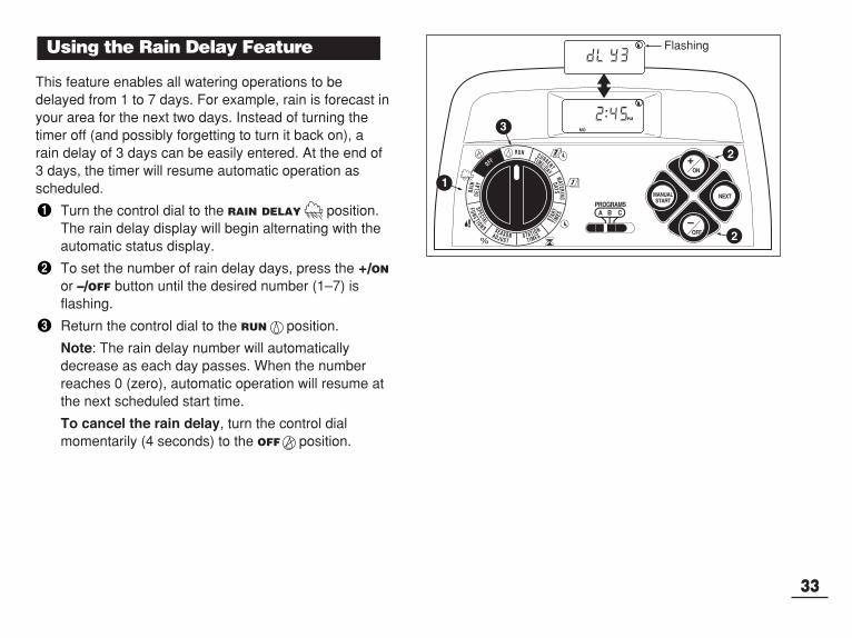
This feature enables all watering operations to bedelayed from 1 to 7 days. For example, rain is forecast inyour area for the next two days. Instead of turning thetimer off (and possibly forgetting to turn it back on), arain delay of 3 days can be easily entered. At the end of3 days, the timer will resume automatic operation asscheduled.
Turn the control dial to the RAIN DELAY position.The rain delay display will begin alternating with theautomatic status display.
To set the number of rain delay days, press the +/ON
or –/OFF button until the desired number (1–7) isflashing.
Return the control dial to the RUN position.
Note: The rain delay number will automaticallydecrease as each day passes. When the numberreaches 0 (zero), automatic operation will resume atthe next scheduled start time.
To cancel the rain delay, turn the control dialmomentarily (4 seconds) to the OFF position.
Using the Rain Delay Feature
3
2
2
1
Flashing
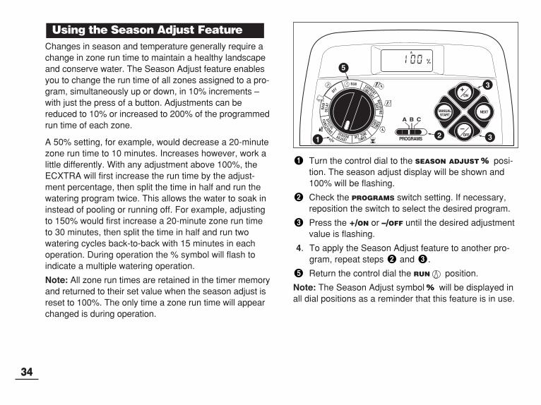
Changes in season and temperature generally require achange in zone run time to maintain a healthy landscapeand conserve water. The Season Adjust feature enablesyou to change the run time of all zones assigned to a pro-gram, simultaneously up or down, in 10% increments –with just the press of a button. Adjustments can bereduced to 10% or increased to 200% of the programmedrun time of each zone.
A 50% setting, for example, would decrease a 20-minutezone run time to 10 minutes. Increases however, work alittle differently. With any adjustment above 100%, theECXTRA will first increase the run time by the adjust-ment percentage, then split the time in half and run thewatering program twice. This allows the water to soak ininstead of pooling or running off. For example, adjustingto 150% would first increase a 20-minute zone run timeto 30 minutes, then split the time in half and run twowatering cycles back-to-back with 15 minutes in eachoperation. During operation the % symbol will flash toindicate a multiple watering operation.
Note: All zone run times are retained in the timer memoryand returned to their set value when the season adjust isreset to 100%. The only time a zone run time will appearchanged is during operation.
Turn the control dial to the SEASON ADJUST posi-tion. The season adjust display will be shown and100% will be flashing.
Check the PROGRAMs switch setting. If necessary,reposition the switch to select the desired program.
Press the +/ON or –/OFF until the desired adjustmentvalue is flashing.
4. To apply the Season Adjust feature to another pro-gram, repeat steps and .
Return the control dial the RUN position.
Note: The Season Adjust symbol will be displayed inall dial positions as a reminder that this feature is in use.
Using the Season Adjust Feature
34
5
3
321

When the control dial is turned to the OFF position, thetimer immediately shuts off any watering operation cur-rently in progress. Leaving the control dial in the OFF
position will prevent all automatic and manual wateringoperations. The timer will continue to track the currenttime and day of the week.
Turn the control dial to the OFF position.
The word OFF will be displayed for approximatelyeight minutes. The display will then revert to theautomatic status display showing the current timeand day.
For extended shutdown of the sprinkler system leavethe control dial in the OFF position.
To resume automatic and manual operation, turn thecontrol dial to the RUN position.
Turning Off the Timer
35
2
1

Once programmed, the ECXTRA memory will beretained for several years with or without power. Only the current time and date information will be lost and willneed to be reset if power is disconnected for more than24 hours. The programmable memory can cleared and reset to thedefault settings of individual programs or all programssimultaneously. (Refer the the default settings listed onpage 21.)
IMPORTANT: This procedure permanently erases the pro-grammable watering information and can not be automati-cally restored once the procedure has been completed.
To clear the memory of a selected program (Example 1)
Turn the control dial to the SEASON ADJUST
position.
Check the PROGRAMS switch setting. If necessary,reposition the switch to select the desired program.Press the NEXT button to access the clear memoryfeature; CL will be displayed and begin flashing.Press and hold the –/OFF button until CL stops flashing (approximately five seconds). The memorywill be cleared to the default settings.
5. To clear the memory of another program, repeat allof the steps starting at step .
Return the control dial to the RUN position.
To clear the memory of all programs (Example 2)
Turn the control dial to the OFF position.
Press the NEXT button to access the clear memoryfeature; CL will be displayed and begin flashing.Press and hold the –/OFF button until CL stops flashing (approximately five seconds). The memorywill be cleared to the default settings. Return the control dial to the RUN position.
Clearing the Program Memory
Service and Specifications
36
Example 1
Example 2

The ECXTRA features built-in circuit protection to helpprevent damage to the timer caused by excessive currentdraw on the zone and/or pump/master valve circuits. The instant an overload condition is detected, the affect-ed zone is turned OFF and thenext zone in the wateringsequence is turned ON. Theword “Fuse” and the bypassedzone number(s) will be beginflashing. If the condition occurs on the pump/master valvecircuit, the timer will alternately display MV and FUSEand discontinue the programoperation.
To clear the warning display,press the –/OFF button. Thetimer will resume normal operationas scheduled and will attempt torun all zones as programmed.
IMPORTANT: Clearing the display does not correctthe problem. The timer will continue to bypass theaffected zones or discontinue operation until theoverload condition is eliminated. Before continuingto operate the timer, take corrective action to resolvethe cause of the problem. Generally this condition iscaused by a faulty valve solenoid or pump start relay.
1. Turn the control dial to the OFF position.
2. Remove the lower front cover from the timer housingby sliding it downward.
3. Place the back of the zone control module (model #53741) squarely between the guides of the first openexpansion slot (from left to right). Pushing lightly onthe bottom of the module, slide it upward until it locksinto position.
4. To connect the valve wires, refer to “Connecting TheValves” on page 7 or 11.
5. Install the lower front cover.
6. To set the zone run time, refer to “Setting Zone RunTimes” on page 28.
7. To test the operation of the new watering zone(s),refer to “Manual Operation” on page 31.
Adding a Zone ModuleAutomatic Circuit Protection
37
DELAY 24HR
12H
R
7 4 3 2 1 8

38
If you are having a problem with the timer, check the following symptoms, possible causes and remedies. If the problem cannot be resolved or you would like assistance with any Toro irrigation product, call our toll-free Toro Help Line, 1-800-367-8676, Monday through Friday, 7:30 AM – 4:00 PM (Pacific Standard Time).
Troubleshooting
Possible Cause
Main power is disconnected.
Watering programs have overlappingschedules.
Faulty control valve wire connections.
Automatic Circuit Protection has disabled the zone.
Zone run time is turned Off.
Control valve problem.
More than one start time on the program.
Season Adjust setting greater than100%.
Remedy
Check the transformer connections(indoor model) or circuit breaker service panel (outdoor model).
Shorten zone run times and/or spacestart times farther apart.Review Season Adjust factor (p. 34)and/or Well Recovery Delay (p. 28).
Check the wire connections at thecontrol valve and timer.
Check for faulty valve solenoid andreplace if necessary.
Enter a zone run time (p. 28)
Inspect, clean and/or repair valve as needed.
Remove additional program starttimes (p. 27).
Review Season Adjust factor (p. 34).
Symptom
The display is blank and thetimer does not operate.
Watering programs start atunscheduled times.
Watering zone does not turn on.
Watering zone does not turn off.
Program restarts unexpectedlyafter the completion of an automatic operation.
.

Cabinet Dimensions:Indoor Model7.5" W x 6.25" H x 2" D (19cm W x 15.9cm H x 5cm D)Outdoor Model13.25" W x 9" H x 3.5" D (33.7cm W x 22.9cm H x 9cm D)Power Specifications:Indoor ModelPlug-in Transformer, Class 2, UL Listed, CSA Certified(or equivalent)• Input: 120 V a.c. 60 Hz, 0.5A• Output: 24 V a.c. 60 Hz, 18 VAOutdoor ModelBuilt-in Transformer, Class 2, UL Listed, CSA Certified(or equivalent)• Input: 120 V a.c. 60 Hz, 0.5A• Output: 24 V a.c. 60 Hz, 20–30 VA Maximum Current Load Per Zone:0.30 Amps @ 24 V a.c. Maximum Current Load For Pump/Master Valve:0.30 Amps @ 24 V a.c. Total Maximum Current Output: One zone pluspump/master valve. Must not to exceed 0.60 Amps@ 24 V a.c. Temperature Limit Range:Operating – 14°F to 140°F (-10°C to 60°C)Storage – -22°F to 149°F (-30°C to 65°C).
Automatic Circuit Protection A built-in circuit protection circuit designed to preventdamage to the timer caused by a faulty valve solenoid orpump start relay. The instant an overload current condi-tion is detected, the affected zone is turned OFF and thenext zone in the watering sequence is turned ON.
Automatic Control ValveAn electrically activated valve which controls the flow ofwater from the source to the sprinkler zone.
Scheduling AdvisorAn exclusive Toro software program which guides youeasily through the ECXTRA programming process toselect the optimum watering schedule for your landscape.
Calendar ScheduleA Calendar schedule enables you to select specific daysof the week to water, for example, Monday, Wednesdayand Friday. This is a seven-day schedule which starts onSunday and ends on Saturday.
Day ExclusionThis feature enables you prevent watering on specificdays of the week when using an Interval or an Odd/Evenwatering day schedule.
Indoor Timer ModelA timer model specifically designed for installation in aprotected environment, such as a house or garage.
Manual OperationOperation of the timer by manually starting a wateringcycle or individual zone.
Glossary of TermsSpecifications
39

40
Master ValveA valve installed between the water source and irrigationvalves to control water flow to the irrigation system. Thetimer automatically turns on the Master Valve circuit atthe beginning of each watering cycle.
Normally ClosedAn electrical switch or circuit that is closed when it is offand open when it is on.
Normally OpenAn electrical switch or circuit that is open when it is offand closed when it is on
Odd/Even ScheduleThe Odd/Even schedule enables you to select odd oreven numbered days of the month as watering days.
Outdoor Timer ModelA timer model with an enclosure designed to for eitherindoor or outdoor installation.
Plug-in ModuleA small module that plugs into the Toro ECXTRA timerto provide connection and operation of two additionalzones.
Power SupplyThe plug-in transformer used to convert 115 V a.c. to 24V a.c. for timer operation.
Pump/Master Valve Control CircuitAt the beginning of each watering cycle, before the firstsprinkler valve is turned on, the Pump/Master Valve Cir-cuit is energized to either start the system pump or openthe master valve.
Pump Delay TimeThe amount of time the Pump/Master Valve control cir-cuit is energized before watering begins. The delay timeis adjustable from 1 to 60 seconds.
Pump Start RelayWhen the ECXTRA timer is used to start a pump, a 24 Va.c. relay switch is used to connect high voltage to thepump starter. The timer is not designed to connectdirectly to the pump start circuit.
Rain DelayThis feature enables all watering operations to bedelayed from 1 to 7 days. For example, rain is forecast inyour area for the next two days. Instead of turning thetimer off (and possibly forgetting to turn it back on), arain delay of 3 days can be easily entered. At the end of3 days, the timer will resume automatic operation asscheduled.
Rain SensorA rain sensor is a remote device which can be connect-ed directly to your ECXTRA to automatically interruptwatering during rain. When the rain sensor absorbs rainwater it automatically signals the ECXTRA to suspend allwatering operations.
Rain Sensor Control SwitchThe sensor control switch is provided to enable the sen-sor operation to be turned On and Off as needed.
Rain Sensor Configuration SwitchRain sensors can be Normally Open or Normally Closedtype. The Rain Sensor Configuration Switch enables youto use either type of sensor with the ECXTRA timer byplacing the switch in the appropriate position.

Scheduling Planning how long to water (zone run time), when towater (program start time) and which days to water(watering days).
Season AdjustSeason Adjust enables the run time of all zones to beadjusted up or down simultaneously in 10% incrementsfrom 10% to 200%. Any increase over 100% will firstincrease the time by the adjusted percentage, then splitthe time in half and run the watering cycle twice.
Sensor Connection TerminalsSnap-in terminals for connection of a rain sensingdevice.
Start TimeA start time is the time of day selected to begin thewatering cycle. Each program (A, B and C) can have upto 4 separate start times.
Terminal BlockConnection point for 115 V a.c. input power in the Out-door model timer
Time PodPortable electronic device used to transport ECXTRAwatering schedule information from the PC based usingCAS software to the ECXTRA timer.
TransformerSee (Power Supply)
Valve Common WireOne wire from each sprinkler control valve which con-nects to the timer "COM" terminal.
Watering ProgramA watering program (or schedule) is the informationstored in the timer memory that determines when anautomatic watering cycle will occur and how long eachzone will water. The timer requires three basic instruc-tions to operate automatically:• Which days to water –called watering days.• What time to start the watering program cycle –
called program start time.• How long each zone will water during the cycle –
called zone run timeWatering DayThe day(s) of the week selected to water.
Watering Program CycleThe ECXTRA is designed to operate one sprinkler zoneat a time. When a scheduled start time occurs, the firstscheduled zone (with the lowest zone number) startsand waters for it’s set length of run time. When the zonehas watered for its set run time, The next zone starts andruns for its programmed run time. This is called a water-ing cycle.
ZoneEach valve controls a specific group of sprinklers calleda watering zone. The zones are generally laid out andinstalled according to the type of plant material to bewatered, such as a lawn or flower bed. Each valve isconnected to a numbered terminal within the timer, iden-tifying it as Zone 1, Zone 2, etc.
Zone Run TimeThe length of time a zone will operate during a wateringcycle. Run time can be set from 1 minute to 4 hours. 41

The Toro Promise — Limited One-Year WarrantyThe Toro Company and its affiliate, Toro Warranty Company, pursuant to anagreement between them, jointly warrants, to the owner against defects in mate-rial and workmanship for a period of one year from the date of purchase.
Neither The Toro Company nor Toro Warranty Company is liable for failure ofproducts not manufactured by them even though such products may be sold orused in conjunction with Toro products.
During such warranty period, we will repair or replace, at our option, any partfound to be defective.
Return the defective part to the place of purchase.
Our liability is limited solely to the replacement or repair of defective parts. Thereare no other express warranties.
This warranty does not apply where equipment is used, or installation is per-formed, in any manner contrary to Toro’s specifications and instructions, norwhere equipment is altered or modified.
NEITHER THE TORO COMPANY NOR TORO WARRANTY COMPANY ISLIABLE FOR INDIRECT, INCIDENTAL OR CONSEQUENTIAL DAMAGES INCONNECTION WITH THE USE OF EQUIPMENT, INCLUDING BUT NOT LIM-ITED TO: VEGETATION LOSS, THE COST OF SUBSTITUTE EQUIPMENTOR SERVICES REQUIRED DURING PERIODS OF MALFUNCTION OR RESULTING NON-USE, PROPERTY DAM-AGE OR PERSONAL INJURY RESULTING FROM INSTALLER’S NEGLI-GENCE.
Some states do not allow the exclusion or limitation of incidental or consequen-tial damages, so the above limitation or exclusion may not apply to you.
ALL IMPLIED WARRANTIES, INCLUDING THOSE OF MERCHANTABILITYAND FITNESS FOR USE, ARE LIMITED TO THE DURATION OF THISEXPRESS WARRANTY.
Some states do not allow limitations of how long an implied warranty lasts, sothe above limitation may not apply to you.
This warranty gives you specific legal rights and you may have other rightswhich vary from state to state.
Domestic: This equipment has been tested an found to comply with thelimits for a Class B digital device, pursuant to Part 15 of the FCC Rules.These limits are designed to provide reasonable protection against harm-ful interference in a residential installation. This equipment generates,uses and can radiate radio frequency energy and, if not installed andused in accordance with the instructions, may cause harmful interferenceto radio communications. However, there is no guarantee that interfer-ence will not occur in a particular installation. If this equipment doesharmful interference to radio or television reception, which can be deter-mined by turning the equipment off and on, the user is encouraged to tryto correct the interference by one or more of the following measures:
1. Reorient or relocate the receiving antenna.
2. Increase the separation between the equipment and receiver.
3. Connect the equipment into an outlet on a circuit different from that towhich the receiver is connected.
4. Consult the dealer or an experienced radio/TV technician for help.
The user may find the following booklet prepared by the Federal Com-munications Commission helpful:
“How To Identify and Resolve Radio-TV Interference Problems”. Thisbooklet is available from the U.S. Government Printing Office, Washing-ton, DC 20402. Stock No. 004-000-00345-4.
International: This is a CISPR 22 Class B product.
Warranty
42
Electromagnetic Compatibility
© 2004 The Toro Company, Consumer Division • An ISO 9000-certified CompanyP.O. Box 489, Riverside CA, 92502 • Toro HelpLine - 800-895-4922 • www.toro.com Form Number 373-0339 Rev. A